

Page 1

R&S®TA-TRS
RF Performance Testing
User Manual
(?LëË2)
1528936102
Version 05
Page 2

This manual applies to the following options:
●
R&S QuickStep Sequencer (1528.9049.02)
●
R&S QS-ETM (1528.9110.02)
●
R&S QS-ETMU (1529.9126.02)
The contents of this manual correspond to R&S QuickStep Sequencer version 4.60 or higher.
The firmware of the instrument uses several valuable open source software packages. For information, see the "Open Source
Acknowledgment" document, which is available for download from the customer web section on GLORIS, the global
Rohde & Schwarz information system: https://extranet.rohde-schwarz.com.
Rohde & Schwarz would like to thank the open source community for their valuable contribution to embedded computing.
© 2021 Rohde & Schwarz GmbH & Co. KG
Mühldorfstr. 15, 81671 München, Germany
Phone: +49 89 41 29 - 0
Email: info@rohde-schwarz.com
Internet: www.rohde-schwarz.com
Subject to change – data without tolerance limits is not binding.
R&S® is a registered trademark of Rohde & Schwarz GmbH & Co. KG.
Trade names are trademarks of the owners.
1528.9361.02 | Version 05 | R&S®TA-TRS
The following abbreviations are used throughout this manual: R&S® is abbreviated as R&S ; e.g. R&S®TA-TRS is abbreviated as
R&S TA-TRS.
Page 3

R&S®TA-TRS
2.1 EN303340....................................................................................................................... 6
2.1.1 One Box Setup................................................................................................................6
2.1.2 Multi Box Setup............................................................................................................... 7
2.2 EN303345....................................................................................................................... 8
2.2.1 One Box Setup................................................................................................................8
2.2.2 Multi Box Setup............................................................................................................... 9
2.3 EN303372-2.................................................................................................................. 11
2.3.1 One Box Setup.............................................................................................................. 11
Contents
Contents
1 R&S TA-TRS Overview...........................................................................5
2 Prerequisites.......................................................................................... 6
2.3.2 Multi Box Setup............................................................................................................. 12
3 Starting TA-TRS....................................................................................14
3.1 Quickstep Setup..........................................................................................................14
3.2 Instrument Setup Menu.............................................................................................. 15
3.2.1 QS-ETM........................................................................................................................ 15
4 Test Setup............................................................................................. 18
4.1 EN303340 & EN303372 Automated Test Setup.........................................................18
4.2 EN303340 & EN303372 Automated Test Setup with Camera.................................. 19
4.3 EN303345 Automated Test Setup.............................................................................. 21
5 Test Configuration............................................................................... 24
5.1 Test Properties............................................................................................................ 24
5.1.1 File Settings.................................................................................................................. 24
5.1.2 ReRun Settings............................................................................................................. 24
5.1.3 General Dialog.............................................................................................................. 25
5.1.4 Compensation Dialog....................................................................................................32
5.1.5 Remote Control DUT Dialog......................................................................................... 33
5.1.6 Signal Mode List Dialog................................................................................................ 33
5.2 Test Cases....................................................................................................................35
5.2.1 EN303340..................................................................................................................... 35
5.2.2 EN303345 Test Case.................................................................................................... 40
3User Manual 1528.9361.02 ─ 05
Page 4

R&S®TA-TRS
5.2.3 EN303372-2 Test Case.................................................................................................44
6.1 Compensating Losses................................................................................................46
6.1.1 Compensation Setup.....................................................................................................48
6.1.2 Instrument Configuration...............................................................................................49
6.1.3 Status............................................................................................................................ 51
6.1.4 Result and Normalization Tab....................................................................................... 51
6.1.5 Compensation File Save / Open................................................................................... 52
6.2 Learning DUT IR Commands..................................................................................... 52
6.2.1 RedRat Prerequisites.................................................................................................... 52
6.2.2 Start RedRat................................................................................................................. 54
6.2.3 Teaching RedRat...........................................................................................................56
Contents
6 Test Preparation................................................................................... 46
6.2.4 Constructing Sequences............................................................................................... 58
6.3 AVB Camera Setup......................................................................................................60
6.3.1 AVB Camera Prerequisites............................................................................................61
6.3.2 AVB Camera Connection Test with Pylon Software...................................................... 61
6.3.3 AVB Camera Test Setup................................................................................................63
7 Test Status and Results.......................................................................71
7.1 Test with Auto Mode................................................................................................... 71
7.2 Test with Full Manual Mode........................................................................................72
7.3 Test with Semi Manual Mode......................................................................................73
7.4 Test with Simple Manual Mode.................................................................................. 74
7.5 Test Result................................................................................................................... 75
Index......................................................................................................77
4User Manual 1528.9361.02 ─ 05
Page 5

R&S®TA-TRS
R&S TA-TRS Overview
1 R&S TA-TRS Overview
R&S TA-TRS is a sequencer software tool that is used together with R&S BTC and
certain accessories to provide the user with test automation and test reporting capabilities. The software features a user-friendly interface and unique test configurations such
as compensation loss, multiple interfering signals and smart learning of DUT control
via infrared remote control.
Used together with the R&S Broadcast Instruments, it offers users easy execution and
management of test cases for product validation and production testing. Offers an
automated test platform to perform RF and interoperability tests. In these tests, you
verify your product in accordance to the ETSI standards.
The test suite is designed to optimize the testing time. The versatile configuration
allows you to tailor the tests according to your different requirements, for example you
can perform the tests only on a subset of test signals.
The key facts are as followed:
●
Supports all test cases for EN 303340, EN 303345 and EN 303372-2
●
Automated detection of picture failure point for video and audio
●
Optional camera solution for automated error detection on TV screens
●
Intuitive state-of-the-art GUI with signal path loss compensation
●
Reproducible and consistent test results
●
Future-proof solution since more standards can easily be integrated into the software solution
5User Manual 1528.9361.02 ─ 05
Page 6

R&S®TA-TRS
2.1 EN303340
2 Prerequisites
These required equipment need to be installed before using R&S TA-TRS:
●
Required hardware and operating system
– Standard PC
– Windows 7 as 64 bit version, including service pack 1 and universal C runtime
update (KB2999226) or Windows 8.1, Windows 10 (capped by Windows 7 only
if uses with AVBCAM)
●
R&S QuickStep sequencer software tool V4.60
●
Broadcast Test Center (R&S BTC) firmware version 02.32 or higher.
The following provides information for one or multiple box setup requirements.
Prerequisites
EN303340
2.1.1 One Box Setup
R&S BTC test instrument with the following options:
BTC - Main Signal
●
Broadcast Test Center (R&S BTC)
●
Baseband Generator first channel (R&S BTC-B1)
●
Baseband Generator second channel (R&S BTC-B2)
●
Baseband Main Module, two I/Q paths to RF (R&S BTC-B12)
●
RF Path A, 100 kHz to 3 GHz (R&S BTC-B3103)
●
RF Path B, 100 kHz to 3 GHz (R&S BTC-B3203)
●
Extended Baseband Routing (R&S BTC-K8)
●
Multimedia Generator Suite (R&S BTC-K20 Included in base unit)
●
Arbitrary Waveform Generator (R&S BTC-K35)
●
Basic Stream library (R&S LIB-K70)
●
DVB-T/DVB-H Coder (R&S BTC-K501)
●
DVB-T2 Coder (R&S BTC-K516)
●
DTV Interferers (R&S WV-K1114)
●
AV Distortion Analysis (R&S VT-K2111)
●
HDMI RX 300 MHz (R&S VT-B2361)
●
Power Measurement (R&S BTC-K2055)
●
Power Sensor that BTC supports
●
RedRat IR Remote Controller (R&S BTC-Z)
Camera option for DUT with screen like TV
●
AVB Camera Software (R&S BTC-KT3329)
6User Manual 1528.9361.02 ─ 05
Page 7

R&S®TA-TRS
Prerequisites
●
Camera accessories (R&S BTC-Z3329)
Required files in R&S BTC
●
Stream files: After installing TA-TRS in the PC, TimeCodeTRP.zip file is saved
under
C:\Users\Public\Documents\Rohde-Schwarz\QuickStep\Projects\
●
TimeCodeTRP.zip: Unzip and copy them into D:\TSGEN\AVBrun\
– Grouper_576i_50.trp
– Grouper_720p_50.trp
– Grouper_720p_50_Camera.trp
– Colorbar_720p_50.trp
●
Interferer signals: After installing TA-TRS in the PC,
EN303340_interferer_files_V2.zip file is saved under
C:\Users\Public\Documents\Rohde-Schwarz\QuickStep\Projects\
●
EN303340_interferer_files_V2.zip: Unzip and copy them into
D:\ARB\DTV_INTERFERERS\
– LTE_BS-idle_V3_synth.wv
– LTE_BS-100PC_synth.wv
– Short_UE-Video-Stream_V2.wv
– DVB-T_8MHz.wv (SFU-K354)
EN303340
2.1.2 Multi Box Setup
R&S BTC (1path) and R&S SFE instruments with the following options:
BTC - Main Signal
●
Broadcast Test Center (R&S BTC)
●
Baseband Generator first channel (R&S BTC-B1)
●
Baseband Generator second channel (R&S BTC-B2)
●
Baseband Main Module, one I/Q path to RF (R&S BTC-B11)
●
RF Path A, 100 kHz to 3 GHz (R&S BTC-B3103)
●
Multimedia Generator Suite (R&S BTC-K20 Included in base unit)
●
Basic stream library (R&S LIB-K70)
●
DVB-T/DVB-H Coder (R&S BTC-K501)
●
DVB-T2 Coder (R&S BTC-K516)
●
AV Distortion Analysis (R&S VT-K2111)
●
HDMI RX 300 MHz (R&S VT-B2361)
●
Power Measurement (R&S BTC-K2055)
●
Power Sensor that BTC supports
●
RedRat IR Remote Controller (R&S BTC-Z)
SFE - Interferer Signal
●
Broadcast Tester (R&S SFE)
7User Manual 1528.9361.02 ─ 05
Page 8

R&S®TA-TRS
Prerequisites
●
Memory Expansion (R&S SFE-B3)
●
ARB Waveform Generator (R&S SFE-K35)
●
DTV Interferers (R&S SFU-K354)
Camera option for DUT with screen like TV
●
AVB Camera Software (R&S BTC-KT3329)
●
Camera accessories (R&S BTC-Z3329)
Required files in R&S BTC
●
Stream files: After installing TA-TRS in the PC, TimeCodeTRP.zip file is saved
under
C:\Users\Public\Documents\Rohde-Schwarz\QuickStep\Projects\
●
TimeCodeTRP.zip: Unzip and copy them into D:\TSGEN\AVBrun\
– Grouper_576i_50.trp
– Grouper_720p_50.trp
– Grouper_720p_50_Camera.trp
– Colorbar_720p_50.trp
EN303345
Required files in R&S SFE
●
Interferer signals: After installing TA-TRS in the PC,
EN303340_interferer_files_V2.zip file is saved under
C:\Users\Public\Documents\Rohde-Schwarz\QuickStep\Projects\
●
EN303340_interferer_files_V2.zip: Unzip and copy them into
D:\ARB\DTV_INTERFERERS\
– LTE_BS-idle_V3_synth.wv
– LTE_BS-100PC_synth.wv
– Short_UE-Video-Stream_V2.wv
– DVB-T_8MHz.wv (SFU-K354)
2.2 EN303345
The following provides information for one or multiple box setup requirements.
2.2.1 One Box Setup
R&S BTC test instrument with the following options:
BTC - Main Signal
●
Broadcast Test Center (R&S BTC)
●
Baseband Generator first channel (R&S BTC-B1)
●
Baseband Generator second channel (R&S BTC-B2)
●
Baseband Main Module, two I/Q paths to RF (R&S BTC-B12)
●
RF Path A, 100 kHz to 3 GHz (R&S BTC-B3103)
8User Manual 1528.9361.02 ─ 05
Page 9

R&S®TA-TRS
●
RF Path B, 100 kHz to 3 GHz (R&S BTC-B3203)
●
Extended Baseband Routing (R&S BTC-K8)
●
Multimedia Generator Suite (R&S BTC-K20 Included in base unit)
●
AM/FM RDS RDBS Coder (R&S BTC-PK570)
●
DAB/DAB+/T-DMB Coder (R&S BTC-PK511)
●
T-DMB/DAB Streams (R&S LIB-K51)
●
DRM/DRM+ Coder (R&S BTC-PK519)
●
DRM/DRM+ MDI Stream Library (R&S LIB-K60)
●
Analog A/V RX (R&S VT-B2370)
●
Audio Analysis (R&S VT-K2150)
●
Power Measurement (R&S BTC-K2055)
●
Power Sensor that BTC supports
●
RedRat IR Remote Controller (R&S BTC-Z)
Required files in R&S BTC
●
FM and AM noise source. Above BTC2.30, It is default files under
D:\AUDIOPLAYER\CCIR559\
– AWGN_CCIR559_4500Hz_120s_V3.wav
– AWGN_CCIR559_15kHz_120s_V3.wav
●
DAB stream(LIB-K51 option): Copy them into D:\TSGEN\TDMB_DAB\DAB\
– RED_Sine+_120s_eti_ni_file.dab_c
– PRODUCT-STREAM-01_V1.0.eti
– PRODUCT-STREAM-02_V1.0.eti
●
DRM stream(LIB-K60 option): Copy them into D:\TSGEN\DRM\
– HF.DCP_C
– LFMF.DCP_C
– VHF.DCP_C
– HF_wanted.DCP_C
– HF_unwanted.DCP_C
– LFMF_wanted.DCP_C
– LFMF_unwanted.DCP_C
– VHF_wanted.DCP_C
– VHF_unwanted.DCP_C
Prerequisites
EN303345
2.2.2 Multi Box Setup
R&S BTC(1path) and R&S SFE instruments with the following options:
SFE - Main Signal
●
Broadcast Tester (R&S SFE)
●
Memory Expansion (R&S SFE-B3)
●
AM/FM/RDS Coder (R&S SFE-K170)
9User Manual 1528.9361.02 ─ 05
Page 10

R&S®TA-TRS
●
TRP Player (R&S SFE-K22)
●
T-DMB/DAB Coder (R&S SFE-K11)
●
T-DMB/DAB Streams (R&S SFU-K221)
●
DRM/DRM+ Coder (R&S BTC-PK519)
●
DRM/DRM+ MDI Stream Library (R&S LIB-K60)
BTC - Interferer Signal
●
Broadcast Test Center (R&S BTC)
●
Baseband Generator first channel (R&S BTC-B1)
●
Baseband Generator second channel (R&S BTC-B2)
●
Baseband Main Module, one I/Q path to RF (R&S BTC-B11)
●
RF Path A, 100 kHz to 3 GHz (R&S BTC-B3103)
●
Multimedia Generator Suite (R&S BTC-K20 Included in base unit)
●
AM/FM RDS RDBS Coder (R&S BTC-K570)
●
DAB/DAB+/T-DMB Coder (R&S BTC-K511)
●
T-DMB/DAB Streams (R&S LIB-K51)
●
DRM/DRM+ Coder (R&S BTC-PK519)
●
DRM/DRM+ MDI Stream Library(R&S LIB-K60)
●
Analog A/V RX (R&S VT-B2370)
●
Audio Analysis (R&S VT-K2150)
●
Power Measurement (R&S BTC-K2055)
●
Power Sensor that BTC supports
●
RedRat IR Remote Controller (R&S BTC-Z)
Prerequisites
EN303345
Required files in R&S SFE
●
DAB stream(SFU-K221option): Copy them into D:\TSGEN\TDMB_DAB\DAB\
– RED_Sine+_120s_eti_ni_file.dab_c
– PRODUCT-STREAM-01_V1.0.eti
– PRODUCT-STREAM-02_V1.0.eti
●
DRM stream(LIB-K60 option): Copy them into D:\TSGEN\DRM\
– HF.DCP_C
– LFMF.DCP_C
– VHF.DCP_C
– HF_wanted.DCP_C
– HF_unwanted.DCP_C
– LFMF_wanted.DCP_C
– LFMF_unwanted.DCP_C
– VHF_wanted.DCP_C
– VHF_unwanted.DCP_C
10User Manual 1528.9361.02 ─ 05
Page 11

R&S®TA-TRS
Required files in R&S BTC
●
FM and AM noise source: Above BTC2.30, It is default files under
D:\AUDIOPLAYER\CCIR559\
– AWGN_CCIR559_4500Hz_120s_V3.wav
– AWGN_CCIR559_15kHz_120s_V3.wav
DAB stream(LIB-K51 option): Copy them into D:\TSGEN\TDMB_DAB\DAB\
– RED_Sine+_120s_eti_ni_file.dab_c
– PRODUCT-STREAM-01_V1.0.eti
– PRODUCT-STREAM-02_V1.0.eti
●
DRM stream(LIB-K60 option): Copy them into D:\TSGEN\DRM\
– HF.DCP_C
– LFMF.DCP_C
– VHF.DCP_C
– HF_wanted.DCP_C
– HF_unwanted.DCP_C
– LFMF_wanted.DCP_C
– LFMF_unwanted.DCP_C
– VHF_wanted.DCP_C
– VHF_unwanted.DCP_C
Prerequisites
EN303372-2
2.3 EN303372-2
The following provides information for one or multiple box setup requirements.
2.3.1 One Box Setup
R&S BTC test instrument with the following options:
BTC - Main Signal
●
Broadcast Test Center (R&S BTC)
●
Baseband Generator first channel (R&S BTC-B1)
●
Baseband Generator second channel (R&S BTC-B2)
●
Baseband Main Module, two I/Q paths to RF (R&S BTC-B12)
●
RF Path A, 100 kHz to 3 GHz (R&S BTC-B3103)
●
RF Path B, 100 kHz to 3 GHz (R&S BTC-B3203)
●
Extended Baseband Routing (R&S BTC-K8)
●
Multimedia Generator Suite (R&S BTC-K20 Included in base unit)
●
Basic stream library (R&S LIB-K70)
●
DVB-S/DVB-S2, DSNG Coder (R&S BTC-PK508)
●
Additive White Gaussian Noise (AWGN) (R&S BTC-K1040)
11User Manual 1528.9361.02 ─ 05
Page 12

R&S®TA-TRS
Prerequisites
EN303372-2
●
AV Distortion Analysis (R&S VT-K2111)
●
HDMI RX 300 MHz (R&S VT-B2361)
●
Power Measurement (R&S BTC-K2055)
●
Power Sensor that BTC supports
●
RedRat IR Remote Controller (R&S BTC-Z)
Camera Option for DUT with screen like TV
●
AVB Camera Software (R&S BTC-KT3329)
●
Camera accessories (R&S BTC-Z3329)
Required files in R&S BTC
●
Stream files: After installing TA-TRS in the PC, TimeCodeTRP.zip file is saved
under
C:\Users\Public\Documents\Rohde-Schwarz\QuickStep\Projects\
●
TimeCodeTRP.zip: Unzip and copy them into D:\TSGEN\AVBrun\
– Grouper_576i_50.trp
– Grouper_720p_50.trp
– Grouper_720p_50_Camera.trp
– Colorbar_720p_50.trp
2.3.2 Multi Box Setup
R&S BTC(1path) and R&S SFE instruments with the following options:
BTC - Main Signal
●
Broadcast Test Center (R&S BTC)
●
Baseband Generator first channel (R&S BTC-B1)
●
Baseband Main Module, one I/Q path to RF (R&S BTC-B11)
●
RF Path A, 100 kHz to 3 GHz (R&S BTC-B3103)
●
Multimedia Generator Suite (R&S BTC-K20 Included in base unit)
●
Basic Stream Library (R&S LIB-K70)
●
DVB-S/DVB-S2, DSNG Coder (R&S BTC-K508)
●
Additive White Gaussian Noise (AWGN) (R&S BTC-K1040)
●
AV Distortion Analysis (R&S VT-K2111)
●
HDMI RX 300 MHz (R&S VT-B2361)
●
Power Measurement (R&S BTC-K2055)
●
Power Sensor that BTC supports
●
RedRat IR Remote Controller (R&S BTC-Z)
SFE - Interferer Signal
●
Broadcast Tester (R&S SFE)
●
Memory Expansion (R&S SFE-B3)
●
DVB-S/DVB-DSNG Coder (R&S SFE-K3)
●
DVB-S2 Coder (R&S SFE-K8)
12User Manual 1528.9361.02 ─ 05
Page 13

R&S®TA-TRS
Prerequisites
EN303372-2
●
TRP Player(R&S SFE-K22)
Camera Option for DUT with screen like TV
●
AVB Camera Software (R&S BTC-KT3329)
●
Camera accessories (R&S BTC-Z3329)
Required files in R&S BTC
●
Stream files: After installing TA-TRS in the PC, TimeCodeTRP.zip file is saved
under
C:\Users\Public\Documents\Rohde-Schwarz\QuickStep\Projects\
●
TimeCodeTRP.zip: unzip and copy them into D:\TSGEN\AVBrun\
– Grouper_576i_50.trp
– Grouper_720p_50.trp
– Grouper_720p_50_Camera.trp
– Colorbar_720p_50.trp
Required files in R&S SFE
●
Stream files: After installing TA-TRS in the PC, TimeCodeTRP.zip file is saved
under
C:\Users\Public\Documents\Rohde-Schwarz\QuickStep\Projects\
●
TimeCodeTRP.zip: unzip and copy them into D:\TSGEN\AVBrun\
– Grouper_576i_50.trp
– Grouper_720p_50.trp
– Grouper_720p_50_Camera.trp
– Colorbar_720p_50.trp
13User Manual 1528.9361.02 ─ 05
Page 14
R&S®TA-TRS
3.1 Quickstep Setup
Starting TA-TRS
Quickstep Setup
3 Starting TA-TRS
To start using TA-TRS:
●
Install R&S Quickstep
●
Insert the Quickstep Dongle and connect with the instrument.
●
Start the R&S Quickstep from the Windows "Start" menu
The following descries the steps need to be setup and configure in Quickstep to run
TA-TRS:
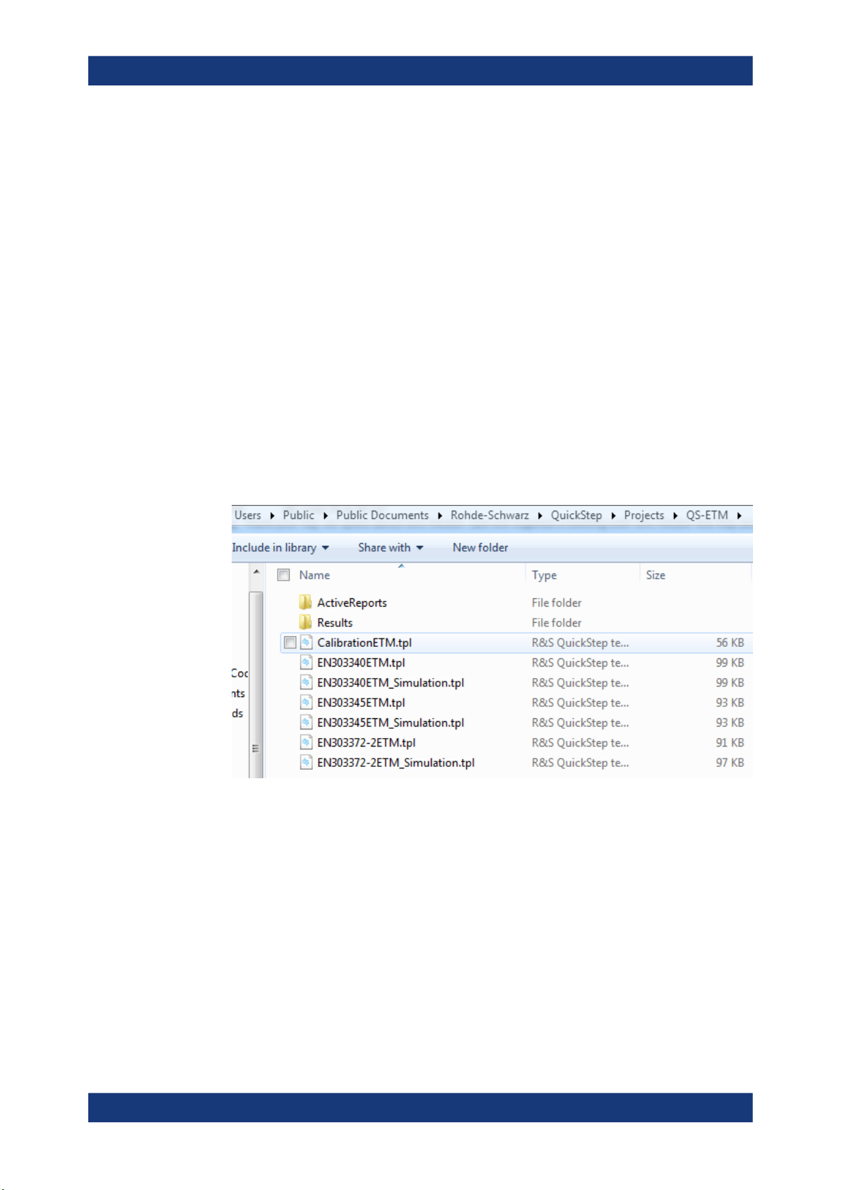
1. Open QuickStep.
2. Select Test Project (.tpl file) - for file with _Simulation naming convention runs
without instruments for demo purpose.
Figure 3-1: Test project files for ETM
a) Under
C:\Users\Public\Documents\Rohde-Schwarz\QuickStep\
Projects\, The folder (QS-ETM) and files are created by installer automati-
cally.
b) QS-ETM: Test projects files for multi legacy instrument solution
3. Over at the "Test Steps" under "Test Project Browser", check that the test plan is
loaded correctly.
14User Manual 1528.9361.02 ─ 05
Page 15

R&S®TA-TRS
Starting TA-TRS
Instrument Setup Menu
Figure 3-2: Test plan name check
4. Set report name, type, path
a) Click "Test Cases" under "Test Procedure Before/After"
b) Set "Report Name"
Default name is "R&S EN303340 Test Report" for EN303340
c) Set "Report Type"
● Default Report type is DOC (Word file)
● Available format: HTML, PDF, PDF + HTML, DOC
d) Set "Report Path"
Default Report path is "C:\QuickStep_Report\EN303340\" for EN303340
Figure 3-3: Report name, type, and path setting
3.2 Instrument Setup Menu
3.2.1 QS-ETM
1. Over at the "Test Steps" under "Test Project Browser", select the Test Plan
15User Manual 1528.9361.02 ─ 05
Page 16

R&S®TA-TRS
Starting TA-TRS
Instrument Setup Menu
Figure 3-4: Instrument setup menu
2. In the"Instrument" combo box, select setup
3. EN303340 / EN303372-2 setup list
● BTC 2 Path
● BTC + SFx
● BTC + SFx +VTx
● SFU + SFx +VTx
4. EN303345 setup list
● BTC 2 Path
● BTC 2 Path + UPx
● SFx + BTC
● SFx + BTC + UPx
5.
Figure 3-5: Configure VISA resource
Click "VISA"
6. Enter correct information Visa Resource
16User Manual 1528.9361.02 ─ 05
Page 17

R&S®TA-TRS
Starting TA-TRS
Instrument Setup Menu
User can input any Visa Resource information or make it blank for instruments that are
not used. For empty information, there is warning message. However, user can ignore
it
17User Manual 1528.9361.02 ─ 05
Page 18

R&S®TA-TRS
4.1 EN303340 & EN303372 Automated Test Setup
Test Setup
EN303340 & EN303372 Automated Test Setup
4 Test Setup
There are different test setups for different standard manually and automatically. All the
different test setups describes in following sub section.
The following setups are for EN303340/EN303372 automated testing for DUT without
screen like set-top box. Based on K8 (Baseband routing) option, additional coupler or
combiner is required. Legacy instrument option allows using SFU and SFE as an interferer signal with 1 path BTC.
Figure 4-1: Instrument setup without K8 option for DUT without screen
Figure 4-2: Instrument setup with K8 option for DUT without screen
18User Manual 1528.9361.02 ─ 05
Page 19

R&S®TA-TRS
Test Setup
EN303340 & EN303372 Automated Test Setup with Camera
Figure 4-3: Instrument setup with legacy instrument for DUT without screen (Optional)
There is a limitation when you use K8 option. Dynamic range between two signals like
wanted signal and unwanted signal is 56 dB. So, result is more than 56 dB, report
shows >56 dB.
The above setup consists of the following:
●
Computer: TA-TRS installed connected to BTC via LAN or GPIB
●
BTC: Proper options that mentioned in Chapter 2, "Prerequisites", on page 6
●
Matching pad: DUT input is 75 ohm and BTC output is 50 ohm
●
RedRat/RedRatX: DUT control for channel searching using IR (infrared) signal,
which connected to computer. You need to run learning process to create control
sequence before testing
●
Coupler or Combiner: without K8 option, it is required to combine two signals
●
Cables: RF cables, HDMI cable, LAN cables
4.2 EN303340 & EN303372 Automated Test Setup with Camera
Please do not use router to connect camera and BTC with PC. It drops transmission
data rate from camera and cause missing frame.
The following setup is for EN303340/EN303372 automated testing with AVB Camera
for DUT with screen like TV.
19User Manual 1528.9361.02 ─ 05
Page 20

R&S®TA-TRS
Test Setup
EN303340 & EN303372 Automated Test Setup with Camera
Figure 4-4: Instrument setup without K8 option for DUT with screen
Figure 4-5: Instrument setup with K8 option for DUT with screen
20User Manual 1528.9361.02 ─ 05
Page 21

R&S®TA-TRS
Test Setup
EN303345 Automated Test Setup
Figure 4-6: Instrument setup with legacy instrument for DUT with screen (Optional)
The above setup consists of the following:
●
Computer: TA-TRS installed connected to BTC via LAN. HDMI port is required with
camera setup
●
BTC: Proper options that mentioned in Chapter 2, "Prerequisites", on page 6
●
Matching pad: DUT input is 75 ohm and BTC output is 50 ohm
●
RedRat/RedRatX: DUT control for channel searching using IR (infrared) signal,
which connected to computer. You need to run learning process to create control
sequence before testing
●
Coupler or Combiner: Without K8 option, it is required to combine two signals
●
Cables: RF cables, HDMI cable, LAN cables
●
AVB Camera software and camera: Camera capture TV screen and stream to PC
via LAN. AVB camera software in PC detects correct video and output it to BTC via
HDMI
●
USB to LAN adapter: Main LAN port in PC is for camera. The adapter is for BTC
control
4.3 EN303345 Automated Test Setup
The following setups are for EN303345 automated testing for Radio receiver DUT like
analog or digital radio. Based on K8 (Baseband routing) option, additional coupler or
combiner is required. Legacy instrument option allows using SFU and SFE as a main
signal only because SFx does not have audio player which requires to play CCIR noise
source for interferer signal.
21User Manual 1528.9361.02 ─ 05
Page 22

R&S®TA-TRS
Test Setup
EN303345 Automated Test Setup
Figure 4-7: Instrument setup without K8 option for Radio receiver
Figure 4-8: Instrument setup with K8 option for Radio receiver
22User Manual 1528.9361.02 ─ 05
Page 23

R&S®TA-TRS
Test Setup
EN303345 Automated Test Setup
Figure 4-9: Instrument setup with legacy instrument for Radio receiver (Optional)
There is a limitation when you use K8 option. Dynamic range between two signals like
wanted signal and unwanted signal is 56 dB. So, result is more than 56 dB, report
shows >56 dB.
The above setup consists of the following:
●
Computer: TA-TRS installed connected to BTC via LAN or GPIB
●
BTC: Proper options that mentioned in Chapter 2, "Prerequisites", on page 6
●
UPL/UPV: Audio quality measurement
●
Matching pad: DUT input is 75 ohm and BTC output is 50 ohm
●
RedRat/RedRatX: DUT control for channel searching using IR (infrared) signal,
which connected to computer. You need to run learning process to create control
sequence before testing
●
Coupler or Combiner: without K8 option, it is required to combine two signals
●
Cables: RF cables, HDMI cable, LAN cables
23User Manual 1528.9361.02 ─ 05
Page 24

R&S®TA-TRS
5.1 Test Properties
Test Configuration
Test Properties
5 Test Configuration
Several dialogs are provided for further test case configuration. The parameters in
these dialogs apply to all test cases in the test suite.
Figure 5-1: Test configuration menu
5.1.1 File Settings
For the File Section, there are three functions as follows:
●
Open Test Setting: Load existing test setting.
●
Open Default Setting: Reset all settings back to default.
●
Save Test Setting: Save the setting for the test for loading in future.
Figure 5-2: File settings menu
5.1.2 ReRun Settings
ReRun features provide convenient test plan and report file generation. Whenever test
is done, TA-TRS generates report file (PDF, HTML, WORD) based on you setting. In
addition, the log file, which contains all test result information, is automatically generated in the same location with the same filename. Using the log file, you can use below
menus.
24User Manual 1528.9361.02 ─ 05
Page 25

R&S®TA-TRS
Test Configuration
Test Properties
Figure 5-3: ReRun Settings menu
For the ReRun Section, there are two functions as follows:
●
ReRun Failed TC
– It works for the test result that is finished
– TA-TRS only run the test cases that have "FAIL" result
– Other "PASS" results are copied to the report without testing
●
Resume Failed TC
– It works for the test result that is stopped or canceled during the test
– TA-TRS find final test position and resume the test
– All results before final test position are copied to the report without testing
5.1.3 General Dialog
In the "Test Properties", select "General" tab.
25User Manual 1528.9361.02 ─ 05
Page 26

R&S®TA-TRS
5.1.3.1 EN303340 and EN303372-2
Test Configuration
Test Properties
Test condition
Figure 5-4: Video test conditions in General dialog
The Test Conditions tab under "General" dialog consists of the followings:
●
Test Setup
Set the test setup. Two setups are available based on BTC-K8 (Baseband routing):
– "2RF Paths"
It uses 2 RF path BTC with combiner or coupler
2 Path Compensation file (*.2comp) is only available for "Compensation Setting"
– "1RF Path (K8)"
It uses 1 RF path BTC with baseband routing option (BTC-K8)
1 Path Compensation file (*.1comp) is only available for "Compensation Setting"
●
Method
Set the test method. Two approaches are available:
– "Detailed Method"
Iterates through a range of levels to find out the exact level where the picture
failure happens in the DUT
– "Quick Method"
Directly tests the DUT with the limit requirement. At the end of the test, a
Passed/failed verdict is given
●
"Picture Degradation Judgement"
26User Manual 1528.9361.02 ─ 05
Page 27

R&S®TA-TRS
Test Configuration
Test Properties
Select the mode of the picture failure point measurement.
– "Auto"
Measures the picture failure using the AV distortion analyzer application.
Requires AV distortion analysis (R&S VT-K2111) with HDMI hardware. If this
option is not installed, you can perform the measurement manually.
– "Manual"
Measures the picture failure using the human eyes. Watch the TV screen to
judge the picture failure point. For manual mode, it is classified to "Full Manual", "Semi Manual" and simple manual. It is describes in detail in the Chap-
ter 7, "Test Status and Results", on page 71 section. Alarm can be sounded
during either start or finish by checking on the "Start" and "Finish" checkbox.
Figure 5-5: Manual mode with sound alarm selection
●
A/V Interface
Select the input signal for measurement. The available signals depend on the
installed options and modules
– "HDMI"
HDMI input of the HDMI RX module (R&S VT-B2361)
– "Composite"
Composite input of the A/V RX module (R&S VT-B2370)
– "Camera"
Camera input module (R&S BTC-KT3329 & BTC-Z3329)
●
Test Video Stream
Select the video stream for the test.
The stream location is D:\TSGEN\AVBrun\ on the R&S BTC. Default steam is
Grouper_720p_50.trp. You can also load your own stream after changing filename
to User.trp and save it to the stream location.
To change video output format for DUT using EDID, check on the "EDID Loading"
checkbox.
27User Manual 1528.9361.02 ─ 05
Page 28

R&S®TA-TRS
Test Configuration
Test Properties
Picture failure
Figure 5-6: Picture Failure in General dialog
The Picture Failure tab under "General" dialog consists of the followings:
●
Visible Error Definition
To define the quality parameters used for A/V analysis to reliably assess video
quality and detect any deviation from a reference signal. PSNR and SSIM are the
objective metric and most commonly used for quality measurements of compressed images.
– "SSIM"
Define structural similarity index to be used for the threshold limit setting for
picture failure point measurement. The value range is 0 dB to 1 dB and value of
1 is achieved if there is two similar sets of data. Recommended is 0.97
– "PSNR"
Define peak signal to noise ratio to be used for the threshold limit setting for
picture failure point measurement. The value range is 0 dB to 100 dB. The
higher the value, the better the quality. Recommended are 35 dB.
– "Measurement Duration"
Define measurement period. The value range is 20 ms to 999 ms. Recommended is 200 ms.
●
Reference Video Quality
Define the reference video quality for Auto test. Auto test is required to make reference video file. After making it, TA-TRS will check whether the quality is good
enough. If the result is lower than threshold, the test stops and issues a warning
message
– "Threshold"
28User Manual 1528.9361.02 ─ 05
Page 29

R&S®TA-TRS
Test Configuration
Test Properties
Defines SSIM or PSNR value for threshold. Recommended are 100 dB for
PSNR and 1 for SSIM with HDMI input video.
Note: Using camera for A/V interface, Threshold value is changed automatically because the setup has more noise and uncertainty. Recommended are 37
dB for PSNR and 0.98 for SSIM
●
Onset of Picture Degradation
To determine the picture failure, the signal quality is evaluated. The evaluation is
determined by degradation criteria specified in the test standard.
– "Time"
Defines how many seconds a period should last. Recommended default is 15
s.
●
Measurement Delay Time after RF setting
After changing RF parameter especially level, it needs some time for error-free
from instrument effect.
– "Time"
Defines the delay time after setting the RF. Recommended is 1000 ms.
5.1.3.2 EN303345
Test condition
Figure 5-7: Audio test conditions in General dialog
The Test Conditions tab under General dialog consists of the followings:
●
Test Setup
Set the test setup. Two setups are available based on BTC-K8 (Baseband routing):
– "2RF Paths"
It uses 2 RF path BTC with combiner or coupler 2 Path Compensation file
(*.2comp) is only available for "Compensation Setting".
– "1RF Path (K8)"
29User Manual 1528.9361.02 ─ 05
Page 30

R&S®TA-TRS
Test Configuration
Test Properties
It uses 1 RF path BTC with baseband routing option (BTC-K8) 1 Path Compensation file (*.1comp) is only available for "Compensation Setting".
●
"Audio Degradation Judgement"
Select the mode of the audio failure point measurement.
– "Auto"
Measures the audio failure using Audio analyzer. Requires additional instrument UPL or UPV. If Audio analyzer is not available, you can perform the measurement manually.
– "Manual"
Measures the audio failure using the human ears. Listen audio signal to judge
the audio failure point. For manual mode, it is classified to Full manual, Semi
manual and simple manual. It is describes in detail in the Chapter 7, "Test Sta-
tus and Results", on page 71 section. Alarm can be sounded during either
start or finish by checking on the Start and Finish checkbox.
●
"Audio Interface"
Select the input signal for measurement.
– "Composite"
Composite input of the A/V RX module (R&S VT-B2370).
●
"Measurement Setup"
Select type of setup for measurement. Two approaches are available:
– "Conducted"
Measurement setup will be done in conducted mode.
– "Radiated"
Measurement setup will be done in radiated mode.
Note: For "Radiated", limit line and level unit are changed based on standard. You
need to apply TEM-cell factor into compensation file during Compensating Losses.
●
Measurement Channel
Set the measurement channel. Two channels are available:
– "Left (Ch1)"
Ch1 is selected as the measurement channel.
– "Right (Ch2)"
Ch2 is selected as the measurement channel.
30User Manual 1528.9361.02 ─ 05
Page 31

R&S®TA-TRS
Test Configuration
Test Properties
Audio failure
Figure 5-8: Audio Failure in General dialog
The "Audio Failure" tab under "General" dialog consists of the followings:
●
"Impairment Criteria"
Judgment parameters for analog radio.
– SNR: Standard mentioned threshold (28dB for AM, 40dB for FM).
– ─ Audio: Manual listening test
Judgment parameters for digital radio
– Audio: Manual listening test
– THDN (Optional): Standard does not mentions parameter for measurement.
Result with THDN is closed to manual listening. TA-TRS uses it as optional
method
●
"Sufficient Audio Level Range"
Define the sufficient audio level range. By default the range is set to 0.3 V to 0.8 V.
●
"Clean Audio"
Define the time for clean audio. By default the time is set to 10 s.
●
"Measurement Delay Time after RF Setting"
Only available if “Auto” test method is used. Define the delay time before any automated measurement to allow the DUT to settle down/pick-up the signal. By default
the time is set to 1000 ms.
31User Manual 1528.9361.02 ─ 05
Page 32

R&S®TA-TRS
5.1.3.3 Report for All Test Cases
Test Configuration
Test Properties
Figure 5-9: Report information in General dialog
The "Report" tab under "General" dialog consists of the followings:
This information is shown on the first page of the report.
●
"Basic" Tab
Enter the DUT information (Model, Serial Number, Operator and Description) in the
test report.
●
"Additional" Tab
Enter additional information (Up to 3 titles and descriptions) in the test report.
●
"Environment Information"
Enter the environment information (Temperature, Humidity, and Uncertainty) in the
test report.
5.1.4 Compensation Dialog
To ensure a precise result for the testing, loss incurred by external parts should not be
neglected. TA-TRS provides auto-compensation methods that use compensation files.
Select the file you want to use as compensation file in the test and load it. Further
details see Chapter 6.1, "Compensating Losses", on page 46 to create a new compensation file using power sensor.
32User Manual 1528.9361.02 ─ 05
Page 33

R&S®TA-TRS
5.1.5 Remote Control DUT Dialog
Test Configuration
Test Properties
Figure 5-10: Compensation loading dialog
To allow full automation, TA-TRS controls the DUT using IR signals (IR remote control).
●
"Load" button
Select the sequence file you want to use in the test.
●
"Make New Sequence" button
Create a new sequence file using the RedRat 3-II or RedRat-X IR remote control.
Further details see Chapter 6.2, "Learning DUT IR Commands", on page 52.
Figure 5-11: Remote control making or loading dialog
5.1.6 Signal Mode List Dialog
The following illustrates the different signal model list dialog.
5.1.6.1 EN303340
TA-TRS specifies the signal information for EN30340 based on standard for DVB-T
and DVB-T2. Default values are from the standard.
33User Manual 1528.9361.02 ─ 05
Page 34

R&S®TA-TRS
Test Configuration
Test Properties
Figure 5-12: EN303340 signal parameters
5.1.6.2 EN303345
TA-TRS specifies the signal information for EN30345 based on standard for AM, FM,
DAB, DRM. Default values are from the standard.
Figure 5-13: EN303345 signal parameters
5.1.6.3 EN303372-2
TA-TRS specifies the signal information for EN30372-2 based on standard for DVB-S,
DVB-S2. Default values are from the standard. It also contains menu for Adjacent Signal stream selection and transponder frequency setting for remote control.
34User Manual 1528.9361.02 ─ 05
Page 35

R&S®TA-TRS
Test Configuration
Test Cases
5.2 Test Cases
5.2.1 EN303340
To select a test case for individual configuration.
Under "Test Case", click the test case name.
The selected test case name is highlighted in blue color. For example above, "4.2.3
Sensitivity" is selected. You can also select all test cases by checking the "Select All"
checkbox. Each individual configuration is applied to the selected test case
35User Manual 1528.9361.02 ─ 05
Page 36

R&S®TA-TRS
Test Configuration
Test Cases
Figure 5-14: Test case selection and details for EN303340
5.2.1.1 4.2.3 Sensitivity
For Sensitivity test arrangement, 1
1. Band selection and frequency.
2. Signal mode selection for DVB-T and DVB-T2 .
3. Limit value (level) for each signal mode and frequency.
36User Manual 1528.9361.02 ─ 05
Page 37

R&S®TA-TRS
Test Configuration
Test Cases
Figure 5-15: 4.2.3 Sensitivity arrangement for EN303340
5.2.1.2 4.2.4 Adjacent Channel Selectivity
Figure 5-16: 4.2.4 Adjacent channel selectivity for EN303340
For Adjacent Channel Selectivity test arrangement:
37User Manual 1528.9361.02 ─ 05
Page 38

R&S®TA-TRS
Test Configuration
Test Cases
1. Band selection with interferer signal.
2. Wanted signal and unwanted signal frequencies.
3. Signal mode selection for DVB-T and DVB-T2.
4. Limit value (I/C) for each signal mode and frequency.
5. Measurement Algorithm
● Start from Limit I/C (Default): Test starts from limit I/C to find picture failure error
Figure 5-17: 4.2.4 Algorithm - Start from Limit I/C
● Test Range Margin: Test starts from limit I/C to find picture failure error. If testing I/C is more/less than margin value (below screen example is 10dB) from
limit line. It stops test and show results like > 45 dB or < 25 dB when limit I/C is
35. It helps you to check certain performance instead of finding picture failure
error.
Figure 5-18: 4.2.4 Algorithm - Test Range Margin
For Adjacent Channel Selectivity test arrangement, select the sensitivity that is need
band selection and wanted signal center frequency, the required sensitivity limit for
DTT configuration for DVB-T and DVB-T2. You can also select to perform either DVB-T
or DVB-T2 or both.
38User Manual 1528.9361.02 ─ 05
Page 39

R&S®TA-TRS
5.2.1.3 4.2.5 Blocking
Test Configuration
Test Cases
For Blocking test arrangement:
1. Band selection with interferer signal.
2. Wanted signal and unwanted signal frequencies.
3. Signal mode selection for DVB-T and DVB-T2.
4. Limit value (Interferer level) for each signal mode and frequency.
5.2.1.4
Figure 5-19: 4.2.5 Blocking for EN303340
4.2.6 Overloading
For Overloading test arrangement:
1. Preamplifier conditions (With Preamp (On/Off) or Without Preamp).
2. Wanted signal and unwanted signal frequencies.
3. Signal mode selection for DVB-T and DVB-T2.
4. Limit value (Interferer level) for each signal mode and preamplifier conditions.
39User Manual 1528.9361.02 ─ 05
Page 40

R&S®TA-TRS
Test Configuration
Test Cases
Figure 5-20: Overloading for EN303340
5.2.2 EN303345 Test Case
It supports three standard versions with latest version EN303 345 -2 to -5 included as
V1.1.1 (2020).
●
V1.1.1
●
V1.1.1 (2020)
●
V1.1.7
Figure 5-21: Version selection menu for EN303345
From TA-TRS software V2 onwards, test case number will be removed from the GUI
for EN303345 testing.
40User Manual 1528.9361.02 ─ 05
Page 41

R&S®TA-TRS
5.2.2.1 4.2.4 Sensitivity
Test Configuration
Test Cases
Figure 5-22: 4.2.4 Sensitivity - Conducted for EN303345
Figure 5-23: 4.2.4 Sensitivity - Radiated for EN303345
For Sensitivity test arrangement, you can change test environment - Radiated or Conducted in "Test condition" on page 26.
1. Band selection for analog and digital.
2. Wanted signal frequency.
3. Limit value (level) for each frequency.
41User Manual 1528.9361.02 ─ 05
Page 42

R&S®TA-TRS
5.2.2.2 4.2.5 Adjacent Channel Selectivity and Blocking
Test Configuration
Test Cases
Figure 5-24: Adjacent Channel Selectivity and Blocking - Conducted for EN303345
Figure 5-25: Adjacent channel selectivity and Blocking - Radiated for EN303345
For Adjacent Channel Selectivity and Blocking test arrangement, you can change test
environment - Radiated or Conducted in "Test condition" on page 26.
1. Band selection for analog and digital.
2. Wanted signal frequency and level.
3. Limit value (I/C) for each offset of frequencies.
42User Manual 1528.9361.02 ─ 05
Page 43

R&S®TA-TRS
Test Configuration
Test Cases
4. "Wanted signal ON During Unwanted signal set": It helps to hold wanted signal during unwanted signal is set.
5. Measurement Algorism
● Start from Limit I/C (Default): Test starts from limit I/C to find audio failure error
Figure 5-26: 4.2.5 Algorism - Start from Limit I/C (Default)
● Test Range Margin: Test starts from limit I/C to find picture failure error. If test-
ing I/C is more/less than margin value (below screen example is 10dB) from
limit line. It stops test and show results like > 45 dB or < 25 dB when limit I/C is
35. It helps you to check certain performance instead of finding picture failure
error.
Figure 5-27: 4.2.5 Algorism - Test Range Margin
43User Manual 1528.9361.02 ─ 05
Page 44

R&S®TA-TRS
5.2.3 EN303372-2 Test Case
5.2.3.1 4.3.1 Adjacent Signal Selectivity
Test Configuration
Test Cases
Figure 5-28: 4.3.1 Adjacent Signal Selectivity for EN303372-2
For Adjacent Signal Selectivity test arrangement:
1. Signal mode selection for DVB-S and DVB-S2.
2. Wanted signal frequency.
3. Low and high symbol rate for DVB-S and DVB-S2.
4. Frequency offset selection and power level offset for interferer signal.
5. Limit value (Result difference between with noise and without noise).
6. Different Constellation for Low & High SR: You can set different constellation for
low & high symbol rate in "Test condition" on page 26.
44User Manual 1528.9361.02 ─ 05
Page 45

R&S®TA-TRS
5.2.3.2 4.3.2 Dynamic Range
Test Configuration
Test Cases
Figure 5-29: 4.3.2 Dynamic Range for EN303372-2
For Dynamic Range test arrangement:
1. Signal mode selection for DVB-S and DVB-S2.
2. Band selection.
3. Wanted signal frequencies and levels.
4. Limit value (Dynamic range).
45User Manual 1528.9361.02 ─ 05
Page 46

R&S®TA-TRS
6.1 Compensating Losses
Test Preparation
Compensating Losses
6 Test Preparation
In order to run the different test cases, you need to provide the following files:
●
Compensation setting file
●
Remote control command sequence file
●
Setting up of AVBCamera for EN303340 and EN303372 automated test with camera setup
A new file should be created if there is no existing compensation setting file or remote
control command sequence file.
TA-TRS provides auto-compensation methods to compensate the loss that occurs in
external parts connected to the R&S BTC and DUT, such as cables and impedance
matching pad.
User need to check frequency range based on standard
The supported power sensors are as follows:
R&S NRP-Z11
R&S NRP-Z21, R&S NRP-Z22, R&S NRP-Z23, R&S NRP-Z24
R&S NRP-Z31
R&S NRP-Z51, R&S NRP-Z52, R&S NRP-Z55, R&S NRP-Z56
R&S NRP-18T
R&S NRP-6A
To create a new compensation file
Select and open the calibration test plan
●
QS-ETM
46User Manual 1528.9361.02 ─ 05
Page 47

R&S®TA-TRS
Test Preparation
Compensating Losses
Figure 6-1: QS-ETM Calibration test project
QS-ETM support multi instrument with Power sensor and R&S spectrum analyzer.
User need to set Visa Resource following to QS-ETM
Figure 6-2: QS-ETM instrument setup
The "Compensation" dialog is displayed.
47User Manual 1528.9361.02 ─ 05
Page 48

R&S®TA-TRS
Test Preparation
Compensating Losses
Figure 6-3: Compensation form
6.1.1 Compensation Setup
Figure 6-4: Compensation setup menu
1. "BTC Setup"
● 2 RF Paths: You need combiner or coupler to add two signals. There are two
steps measurements for path 1 and path 2. Compensation file extension is
*.2comp.
1 RF Path: BTC need K8 (Baseband routing) option. Compensation file extension
is *.1comp.
2. "Type"
Select the type of compensation method.
● "Atten. Absolute": Directly measure the setup loss without reference cable.
48User Manual 1528.9361.02 ─ 05
Page 49

R&S®TA-TRS
Test Preparation
Compensating Losses
● "Atten. Relative": Measure the loss for reference cable and measure the setup
loss with reference cable. Normalization tab appears for reference cable measurement.
Figure 6-5: Atten. Relative type with Normalization tab
6.1.2 Instrument Configuration
BTC setup for compensation.
1. Power
● Level: Compensation power from BTC. Default is 0 dBm.
49User Manual 1528.9361.02 ─ 05
Page 50

R&S®TA-TRS
Test Preparation
Compensating Losses
Figure 6-6: Power menu
2. Frequency
It has a predefine frequency list based on standard.
Figure 6-7: Frequency list selection menu
Below menus are only available when "User Define" is selected. You can change
parameters on their own.
● "Start": Start frequency. Default is 474 MHz
● "Stop": Stop frequency. Default is 850 MHz
● "Step": Step frequency. Default is 8 MHz
3. "Matching Pad loss"
Matching pad is necessary to match the impedance between BTC and DUT. However, power sensor cannot compensate the matching pad because of different
impedance. It is added manually into measured setup loss.
● Constant: Constant value applies to all frequency range. Default is 5.72 dB.
Figure 6-8: Matching pad loss menu
4. "Additional loss"
You can apply additional loss based on frequency. It can be used to add TEM-cell
factor or matching pad loss when loss is different over the frequency.
Figure 6-9: Additional loss menu
● Loss Table: You can create loss table over frequency and save/open it.
50User Manual 1528.9361.02 ─ 05
Page 51

R&S®TA-TRS
Test Preparation
Compensating Losses
Figure 6-10: Additional loss table
6.1.3 Status
It shows the status messages and progress information.
Figure 6-11: Status menu
6.1.4 Result and Normalization Tab
When "Atten. Relative" type is selected, You need to compensate reference cable first
in "Normalization" tab before measure setup loss.
Number of tabs are changed based on "Compensation Setup".
Each tab has a "Start" button that runs individually.
51User Manual 1528.9361.02 ─ 05
Page 52

R&S®TA-TRS
6.1.5 Compensation File Save / Open
Test Preparation
Learning DUT IR Commands
Figure 6-12: Result tab
When compensation is finished, "Save" button is enabled automatically. Compensation
file is used for "Compensation Setting " in Chapter 5.1.4, "Compensation Dialog",
on page 32.
"Open" button is used for checking the compensation file.
Figure 6-13: Compensation save / open menu
6.2 Learning DUT IR Commands
6.2.1 RedRat Prerequisites
Driver needs to be installed before using RedRat. Install correct driver for your Redrat
type - RedRat 3-II or RedRat-X.
6.2.1.1 RedRat 3-II
1. Download driver - Link: https://www.redrat.co.uk/support/firmware-drivers/.
52User Manual 1528.9361.02 ─ 05
Page 53

R&S®TA-TRS
Test Preparation
Learning DUT IR Commands
Figure 6-14: RedRat 3-II driver download menu
2. Extract zip file. It contains system file.
3. Go to "Device Manager" and find "Infrared Remote Control IO".
4. "Update Driver Software" using system file.
6.2.1.2
Figure 6-15: RedRat driver update in Device manager
RedRat-X
1. Download driver - Link: https://www.redrat.co.uk/support/firmware-drivers/
Figure 6-16: Redrat-X driver download menu
2. Extract zip file. It contains exe file.
3. Execute InstallRedRatDriver.exe.
53User Manual 1528.9361.02 ─ 05
Page 54

R&S®TA-TRS
6.2.2 Start RedRat
Test Preparation
Learning DUT IR Commands
To allow full automation, TA-TRS is using the RedRat 3-II or RedRat-X IR remote control to establish an intelligent learning system. Firstly, you teach the RedRat 3-II or
RedRat-X the IR signals of the original DUT remote control. Then you construct the
sequences to remotely control the DUT using the RedRat 3-II or RedRat-X.
The RedRat 3-II or RedRat-X IR remote control consists of a hardware and software
component. The hardware component sends and receives IR signals. The software
component controls the hardware component and is integrated into the TA-TRS.
To display the "Infrared Remote Control" dialog and connect the RedRat 3-II or
RedRat-X.
Open the "Remote Control DUT dialog" and click "Make New Sequence".
Figure 6-17: Make new sequence menu
The "Infrared Remote Control" dialog is displayed.
54User Manual 1528.9361.02 ─ 05
Page 55

R&S®TA-TRS
Test Preparation
Learning DUT IR Commands
Figure 6-18: Infrared remote control menu
It consists of four steps to create remote control file and Instrument need to generate
correct signal for scanning channels.
Figure 6-19: Step selection menu
1. "Learn Functionality of Remote Control"
Mapping IR signal into button in "Software Remote Control".
2. "Test Functionality of Remote Control"
Testing mapped IR signal is generated correctly using button in "Software Remote
Control".
3. "Learn Sequences"
Making the sequence for auto scan or manual scan using button in "Software
Remote Control".
4. "Test Sequences"
Testing the sequence is generated correctly.
If the RedRat 3-II or RedRat-X is not connected, the error message appears.
55User Manual 1528.9361.02 ─ 05
Page 56

R&S®TA-TRS
6.2.3 Teaching RedRat
Test Preparation
Learning DUT IR Commands
Figure 6-20: Missing Redrat error message
Use the original remote control of the DUT to teach the RedRat 3-II or RedRat-X the IR
signal for each button.
1. To create a new functionality file:
Under "Action", select "Step 1: Learning Functionality of Remote Control".
2. To save an IR signal for necessary buttons, repeat the following steps for each button:
● Under "Software Remote Control", an image of the DUT remote control is pro-
vided. Click a button on the remote control image.
The "Signal Input" dialog is displayed.
Figure 6-21: RedRat signal input dialog
● While the "Signal Input" dialog is being displayed, press the corresponding but-
ton on the original remote control to generate an IR signal. This information is
saved and assigned to the button on the remote control image.
● If the IR signal is successfully learned, the "Signal Input" dialog is closed.
● In the "Remote Control DUT" dialog under "Remote Control", the font color of
the button changes form black to white.
56User Manual 1528.9361.02 ─ 05
Page 57

R&S®TA-TRS
Test Preparation
Learning DUT IR Commands
Figure 6-22: Functionality recording procedure
3. After all buttons have been successfully assigned, the remote control image looks
as follows:
Figure 6-23: Necessary buttons mapping
4. To save functionality into the file:
● Under "Functionality", click "Save".
The saved functionality file is used to create new sequence file.
Figure 6-24: Functionality save / open menu
57User Manual 1528.9361.02 ─ 05
Page 58

R&S®TA-TRS
6.2.4 Constructing Sequences
Test Preparation
Learning DUT IR Commands
5. To generate and verify an IR signal of the RedRat 3-II or RedRat-X IR remote control:
● Under "Action", select "Step 2: Test Functionality of Software Remote Control".
6. Under "Software Remote Control", click the button on the remote control image to
check whether IR signal operates correctly.
Construct the sequences to remotely control the DUT after learning all buttons.
It is used for channel or frequency scan for DUT during the test. Before constructing
the sequence, BTC needs to generate proper signal to DUT to work with DUT.
1. Under "Action", select "Step 3: Learn Sequences" to create a new sequence file.
2. Under "Mode", select "Channel/Frequency switching" which is only selection at this
moment.
3. Under "Type of scanning", select one of four options.
Figure 6-25: Type of scanning menu
● "Full Scan - no channel/Frequency"
It is known as auto scan without any additional frequency input during scan
procedure. This mode can cover most of applications.
● " Scan entering Frequency [MHz]"
It is known as manual scan with frequency(MHz) input during scan procedure.
This frequency keeps changing during the actual test. It needs to give timing
information to generate proper frequency (MHz). "Insert Freq.[MHz]" button
works for it. Put "Insert Freq.[MHz]" into sequence when manual frequency is
required during scan procedure.
Figure 6-26: Manual scan with frequency menu
● "Scan entering Frequency [kHz]"
Same with "Scan entering Frequency [MHz]" procedure. Frequency is kHz unit
instead of MHz.
● "Scan Freq.[MHz] & SR[KS/s]"
58User Manual 1528.9361.02 ─ 05
Page 59

R&S®TA-TRS
Test Preparation
Learning DUT IR Commands
It is only for DVB-S/S2. Same with "Scan entering Frequency [MHz]" procedure. It has one more parameter, which is symbol rate.
Figure 6-27: Manual scan with frequency and symbol rate menu
4. Uses the IR signals assigned to the buttons on the "Software Remote Control", as
learned earlier. Click the buttons on the remote control image to create the
sequence list.
Note: During clicking the buttons, RedRat 3-II or RedRat-X must direct to DUT to
control. You can see what is the next step. Between clicking the buttons, delay time
is recorded and saved in the list.
Figure 6-28: Sequence recording example
5. If you want to modify the sequence list:
● In the sequence list table, right-click a row.
● Select either "Insert Line", "Insert Delay", "Delete Line" or "Delete All".
59User Manual 1528.9361.02 ─ 05
Page 60

R&S®TA-TRS
Test Preparation
AVB Camera Setup
Figure 6-29: Sequence modification menu
6. Under "Sequence", click "Save" to save sequence into the file.
The saved sequence file contains not only the sequence list, but also the functionality information. The saved sequence file can be selected in Chapter 5.1.5,
"Remote Control DUT Dialog", on page 33 for controlling the DUT during the test.
Figure 6-30: Sequence save / open menu
7. To generate and verify an IR signal sequence of the RedRat 3-II or RedRat-X IR
remote control:
● Under "Action", select "Step 4:Test Sequences".
● Under "Sequence", select" Channel/Frequency switching" in the "Mode" to play
the sequence list.
6.3 AVB Camera Setup
R&S AVB Camera consists of both the software and hardware required to perform the
video quality measurement. It includes the controlling software for the processing of
the video output from the camera and transmits it to AV Distortion Analyzer. The Hardware consists of the camera, power adaptor and tripod.
The following features shall be provided:
●
Get frames from camera output
●
Crop frame to get the TV screen only
●
Detect time code of each frame
●
Filter out all the disturbed frames
●
Select the best frame
●
Output frame through HDMI port to BTC
60User Manual 1528.9361.02 ─ 05
Page 61

R&S®TA-TRS
6.3.1 AVB Camera Prerequisites
Test Preparation
AVB Camera Setup
These required equipment need to be installed before using AVB Camera on which the
following lists are required:
●
PC
– Windows7 OS
– HDMI output port
●
Installed software
– Pylon 4 Camera Software Suite 4.1.0.3660
– AVB Camera software
●
Accessories
USB to LAN adapter for controlling instruments
– HDMI cable
– 2 x Category 6 shielded GigE cable
– Power over Ethernet device (Optional) - It gives power over Ethernet to camera
instead of using power adapter.
●
4. BTC
– AVB Camera software (R&S BTC-KT3329)
– AV distortion analysis (R&S VT-K2111)
– HDMI RX 300 MHz (R&S VT-B2361)
– Other options in Chapter 2, "Prerequisites", on page 6
6.3.2 AVB Camera Connection Test with Pylon Software
To help and check whether camera is working correctly:
1. Connect power adapter to camera.
2. Connect LAN cable between camera and PC main LAN port.
Note: You should use PC main LAN port to connect PC because of high-speed
data rate from camera. Additional USB to LAN port is needed to connect BTC.
3. Set DHCP for IP address of PC.
61User Manual 1528.9361.02 ─ 05
Page 62

R&S®TA-TRS
Test Preparation
AVB Camera Setup
Figure 6-31: DHCP setting for PC
4. Run the "pylon IP Configurator".
Figure 6-32: Program in start menu
5. Run pylon IP Configurator.
● Set DHCP for camera.
● Click "Refresh" button.
● Check "Status" is "OK".
IP address may be different.
62User Manual 1528.9361.02 ─ 05
Page 63

R&S®TA-TRS
6.3.3 AVB Camera Test Setup
Test Preparation
AVB Camera Setup
Figure 6-33: Pylon IP configurator status
The following shows the AVB camera test setup.
Figure 6-34: AVB camera test setup
6.3.3.1 AVB Camera Hardware Setup
The following describes the procedure for AVB camera test setup:
1. Connect BTC RF port to TV antenna input by RF cable and matching pad.
● Depend on K8 (Baseband routing) option, you may need coupler or combiner.
● It transmits terrestrial or satellite standard signal.
2. Connect camera to PC main LAN port by a LAN cable.
63User Manual 1528.9361.02 ─ 05
Page 64

R&S®TA-TRS
6.3.3.2 AVB Camera Graphical User Interface
Test Preparation
AVB Camera Setup
● Check connection in Chapter 6.3.2, "AVB Camera Connection Test with Pylon
Software", on page 61.
● It transmits video signal to AVB camera software.
3. Connect BTC to PC USB to LAN adapter by a LAN cable.
Recommend to use static IP (ex. 192.168.1.100).
4. Connect PC HDMI output to BTC HDMI (B2361) module input by HDMI cable.
It transmits video signal after processing by AVB camera software.
5. Connect RedRat 3-II or RedRat-X to PC USB port.
Upon analysis, the selected frame is shown on the left window area. On the right hand
side is the analyzer log and camera exposure setting. It indicates the time, frame time
code, for each time code, how many frames have been captured by the camera and
which frame is selected. At the bottom green color area is the "Status" log. It indicates
what operation has been performed.
Figure 6-35: AVB camera GUI
Control Buttons
There are total 12 control buttons. Upon start-up, only "Unlock", "About" and "Exit" button are enabled.
When option key is verified, the control buttons are enabled and allowed to use.
64User Manual 1528.9361.02 ─ 05
Page 65

R&S®TA-TRS
Test Preparation
AVB Camera Setup
Figure 6-36: AVB Camera menu icons
The functionality of each button is listed as follows:
●
"Unlock"
Pop up unlock dialog and connect to BTC to verify option key. Upon success, the
rest of the buttons are enabled.
●
"Crop Display"
Pop up cropping dialog and allow you to select the cropping area. Upon finish, the
analysis of the frame is only done on the cropping area. You are able to press and
drag to select the cropping area.
The recommended area is within upon and bottom blue line and outside the middle
rectangle. This window is auto exit after you finish the cropping. The cropping
area’s information is then saved in a file. So that next time if you need to run the
application, it reads back the information from the file and auto set accordingly as
the cropping area.
Figure 6-37: AVB camera cropping window
●
"Calibration"
Currently is not supported.
●
"Start Analysis"
Start analyzing on the cropping area, detect time code, discard disturbed frames,
select the frame and display on the left display window.
●
"Stop"
Stop analysis.
●
"Camera"
Connect or disconnect camera.
●
"HDMI Out"
65User Manual 1528.9361.02 ─ 05
Page 66

R&S®TA-TRS
Test Preparation
AVB Camera Setup
Output selected frame on the second monitor through HDMI. This is a toggle button, press one more time the application stops outputting frame on the second
monitor.
●
"AutoScroll"
The status log is auto scrolled to the last line.
●
"About"
Pop up about dialog to show software version.
●
"Exit"
Close window and exit from the application.
Capture Frame Window
This is the displayed video after cropping process. It shows timecode at the bottom. If
timecode is not displayed, the window shows black screen when the timecode is not
detected during analysis.
Analyzer Log Area
It shows current frame number and number of captured pictures. Selected frame is
transmitted to BTC. It only works when timecode in the bottom is detected during
analysis.
Camera Properties
●
"Camera Settings"
– Exposure value helps to solve flickering issue and brightness from TV. Default
value is 10000 us.
– Other solution is to change lens setting manually.
●
"Frame Selection Settings"
It decides which picture is transmitted to BTC among captured pictures. First and
last pictures are not counted because it has a chance to be overlapped with other
frame picture.
– "Max Brightness": The most brightest picture is selected
– "2nd Frame": First valid captured picture is selected
– "3rd Frame": Second valid captured picture is selected
– "4th Frame": Third valid captured picture is selected
Figure 6-38: Frame selection example
66User Manual 1528.9361.02 ─ 05
Page 67

R&S®TA-TRS
6.3.3.3 AVB Camera Test Sequence
Test Preparation
AVB Camera Setup
TV backlight cannot be turned on always for power consumption issue. It is the reason
why user need to set backlight setting to max to minimize off time. Even though, each
picture from capturing by camera has different brightness, which can affect AV distortion measurement algorism. AVBCamera helps to send consistent brightness picture
using Frame Selection Settings.
The following are settings required before running TA-TRS.
1. Set the position for TV and camera.
Camera needs to face the center of TV screen to get correct video.
2. Connect all required cables and accessories explained in Chapter 6.3.3, "AVB
Camera Test Setup", on page 63.
3. PC: Set screen resolution of HDMI output which appears as a second monitor.
Screen properties
● Display: 2. R&S HDMI RX
● Resolution: 1920 x 1080 (recommended)
● Orientation: Landscape
● Multiple displays: Extend these displays
Figure 6-39: PC screen setting
4. TV: Turns off all enhanced functions for display and set back light illumination to
maximum to avoid flickering issue.
Note: AV distortion analyzer compares between reference video and incoming
video for picture failure. The latest TV has many enhanced functions like auto
brightness control. It may affect test results because screen keep changing even
human eyes cannot detect. You should turn off all enhanced functions.
5. BTC
67User Manual 1528.9361.02 ─ 05
Page 68

R&S®TA-TRS
Test Preparation
AVB Camera Setup
● Generate DVB-T/T2 or DVB-S/S2 signal depends on DUT support.
Use Grouper_720p_50_Camera.trp under D:\TSGEN\AVBrun folder.
6. DUT: Scan channel to show video.
7. PC: Run AVB Camera software.
Figure 6-40: AVB camera starting window
8. AVB Camera: Option detection.
● Click "Unlock" button.
● Type BTC IP address and click "Connect" button to detect R&S®BTC-KT3329.
Figure 6-41: BTC connection menu for option detection
68User Manual 1528.9361.02 ─ 05
Page 69

R&S®TA-TRS
Test Preparation
AVB Camera Setup
Figure 6-42: Option detection error message
9. AVB Camera: Crop display.
● Click "Crop Display" button.
● Press left mouse button and drag to select the cropping area. It should contain
timecode correctly. The recommend area is within upon and bottom blue line
and outside the middle rectangle. The window is auto exit after you finish the
cropping. The cropping area's information is saved in a file. So that next time if
you need to run the application, it reads back the information from the file and
auto set accordingly as the cropping area.
Figure 6-43: AVB camera cropping window
10. AVB Camera: Video out to BTC.
● Click "HDMI Out" button
● It transmits cropped video to BTC
11. AVB Camera: Analysis
● Click "Start Analysis" button
● AVB camera can captures 4~7 same picture per frame. You can see number of
pictures in below "Captures" column.
● AVB camera selects only one picture to send to BTC by "Frame Selection Set-
tings", which is mentioned in "Camera Properties" on page 66.
69User Manual 1528.9361.02 ─ 05
Page 70

R&S®TA-TRS
Test Preparation
AVB Camera Setup
Note: It is recommended capturing at least five pictures for accurate processing. Depend on crop size, capture speed is changed and it affects number of
captured pictures. If AVB camera cannot detect time code, screen is black and
log information update is stopped. Try to change brightness setting in lens and
camera tilt position.
Figure 6-44: AVB camera processing window
12. PC: Run TA-TRS
● Select "Camera" for "A/V Interface " in "General" menu.
● Before running test cases, it makes reference video and test quality. If quality
checking is failed, change "Frame Selection Settings" in "AVB Camera".
Figure 6-45: Camera selection in General menu
70User Manual 1528.9361.02 ─ 05
Page 71

R&S®TA-TRS
7.1 Test with Auto Mode
Test Status and Results
Test with Auto Mode
7 Test Status and Results
While running the TA-TRS, a "Status Information" window showing the overall and current test status and the signal information uses for the test cases.
When choose "Auto" mode in the picture degradation judgment, the test is auto run by
itself. You can abort the test by clicking the "Abort" button. You can switch between
"Current Test" mode and "Overall Result" mode.
Figure 7-1: Current test mode
71User Manual 1528.9361.02 ─ 05
Page 72

R&S®TA-TRS
Test Status and Results
Test with Full Manual Mode
Figure 7-2: Overall result mode
7.2 Test with Full Manual Mode
When "Full Manual" mode in the picture degradation judgment, there is a manual operation column for you to enter the level and set it using the "Set" button and click "Final
Level" button if the level is the final level. Start the test by clocking on the "Start" button.
During the test, when an error is observed, click the "Error" button, if there is no error,
click the "No Error" button. You can also retest the test again by clicking the "Retest"
button. You can abort the test by clicking the "Abort" button. There also shortcut keys
for some of the button, which stated beside the name of the button.
72User Manual 1528.9361.02 ─ 05
Page 73

R&S®TA-TRS
Test Status and Results
Test with Semi Manual Mode
Figure 7-3: Full manual mode
It is possible for keyboard control using shortcut key.
●
Arrow up: Level or CI value increase
●
Arrow down: Level or CI value decrease
For alternate control, you only need to press ALT+ any below key first time. After activate it, you can press alphabet only without ALT key.
●
ALT + A: Level or CI set
●
ALT + F: Final Level
●
ALT + S: Start test
●
ALT + E: Error
●
ALT + D: No Error
●
ALT + R: Retest
7.3 Test with Semi Manual Mode
When "Semi Manual" mode in the picture degradation judgment, there is a manual
operation column for you to start the test by clocking on the "Start" button. During the
test, when an error is observed, click the "Error" button, if there is no error, click the
"No Error" button. You can also retest the test again by clicking the "Retest" button.
You can abort the test by clicking the "Abort" button. The level and final level is done
automatically. There also shortcut keys for some of the button, which stated beside the
name of the button.
73User Manual 1528.9361.02 ─ 05
Page 74

R&S®TA-TRS
Test Status and Results
Test with Simple Manual Mode
Figure 7-4: Semi manual mode
It is possible for keyboard control using shortcut key.
●
Arrow up: Level or CI value increase
●
Arrow down: Level or CI value decrease
For alternate control, you only need to press ALT+ any below key first time. After activate it, you can press alphabet only without ALT key.
●
ALT + A: Level or CI set
●
ALT + F: Final Level
●
ALT + S: Start test
●
ALT + E: Error
●
ALT + D: No Error
●
ALT + R: Retest
7.4 Test with Simple Manual Mode
When Simple Manual mode is selected in the picture degradation judgment, there is a
"Start (Enter)" button to start the test. When the picture failure will analyze for 15s, if
there is any error observed, click the "Start (Enter)" button and it will auto set to the
next level. You can abort the test by clicking the "Abort" button.
74User Manual 1528.9361.02 ─ 05
Page 75

R&S®TA-TRS
Test Status and Results
Test Result
Figure 7-5: Simple manual mode
7.5 Test Result
After the test had completed or aborted, a test report and log file will be auto generated. The following shows a sample of test report information, test configurations and
test results of the report.
Figure 7-6: Test report information
75User Manual 1528.9361.02 ─ 05
Page 76

R&S®TA-TRS
Test Status and Results
Test Result
Figure 7-7: Test configuration
Figure 7-8: Test result
76User Manual 1528.9361.02 ─ 05
Page 77

R&S®TA-TRS
Index
Index
A
AVB Camera Graphical User Interface
Analyzer Log Area ...................................................... 64
Camera Properties ...................................................... 64
Capture Frame Window .............................................. 64
Control Buttons ........................................................... 64
AVB Camera Setup
AVB Camera Connection Test with Pylon Software ....60
AVB Camera Prerequisites ......................................... 60
AVB Camera Test Setup ............................................. 60
AVB Camera Test Setup
AVB Camera Graphical User Interface ....................... 63
AVB Camera Hardware Setup .................................... 63
AVB Camera Test Sequence ...................................... 63
C
Compensating Losses
Compensation File Save / Open ................................. 46
Compensation Setup .................................................. 46
Instrument Configuration ............................................ 46
Result and Normalization Tab ..................................... 46
Status .......................................................................... 46
E
EN303340
4.2.3 Sensitivity ........................................................... 35
4.2.4 Adjacent Channel Selectivity ............................. 35
4.2.5 Blocking ............................................................. 35
4.2.6 Overloading ....................................................... 35
Picture Failure ............................................................. 25
Test Condition ............................................................. 25
EN303340 & EN303372 Automated Test Setup ............... 18
EN303340 & EN303372 Automated Test Setup with Camera
.......................................................................................... 18
EN303345
4.2.4 Sensitivity ........................................................... 40
4.2.5 Adjacent channel selectivity and Blocking ......... 40
4.3.1 Adjacent signal selectivity .................................. 44
4.3.2 Dynamic range ................................................... 44
Audio Failure ............................................................... 25
Multi Box Setup ............................................................. 8
One Box Setup ............................................................. 8
Test Condition ............................................................. 25
EN303345 Automated Test Setup ..................................... 18
EN303372-2
Multi Box Setup ....................................................... 6, 11
One Box Setup ........................................................ 6, 11
Picture Failure ............................................................. 25
Test Condition ............................................................. 25
P
Prerequisites
EN303340 ..................................................................... 6
EN303345 ..................................................................... 6
EN303372-2 .................................................................. 6
Q
QuickStep
Setup .......................................................................... 14
R
R&S TA-TRS Overview ....................................................... 5
RedRat Prerequisites
RedRat 3-II ................................................................. 52
RedRat-X .................................................................... 52
S
Setup
QuickStep ................................................................... 14
Signal Mode List Dialog
EN303340 ................................................................... 33
EN303345 ................................................................... 33
EN303372-2 ................................................................ 33
T
Test Cases ........................................................................ 35
Test Configuration ............................................................. 24
Compensation Dialog ................................................. 24
File Settings ................................................................ 24
General Dialog ............................................................ 24
Remote Control DUT Dialog ....................................... 24
ReRun Settings ........................................................... 24
Signal Mode List Dialog .............................................. 24
Test Preparation ................................................................ 46
AVB Camera Setup ..................................................... 46
AVB Camera Test Sequence ...................................... 46
Compensating Losses ................................................ 46
Learning DUT IR Commands ..................................... 46
Test Results ....................................................................... 75
Test Setup ......................................................................... 18
Test Status and Results .................................................... 71
Test with Auto Mode ................................................... 71
Test with Full Manual Mode ........................................ 71
Test with Semi Manual Mode ...................................... 71
Test with Simple Manual Mode ................................... 71
L
Learning DUT IR Commands
Constructing Sequences ............................................. 52
RedRat Prerequisites .................................................. 52
Start RedRat ............................................................... 52
Teaching RedRat ........................................................ 52
77User Manual 1528.9361.02 ─ 05
 Loading...