


Satellite Navigation
R&S®SMW-K44/-K66/-K94/-K97/-
K98/-K106/-K107/-K108/-K109/K123/-K132/-K134/-K135/-K136/K137/-K138/-K139
User Manual
(;ÜÍÝ2)
1178637902
Version 13

This document describes the following software options:
●
R&S®SMW-K44 GPS (1413.3832.xx)
●
R&S®SMW-K66 Galileo (1413.3839.xx)
●
R&S®SMW-K94 GLONASS (1414.1485.xx)
●
R&S®SMW-K97 NavIC (1414.6258.xx)
●
R&S®SMW-K98 Modernized GPS (1414.1533.xx)
●
R&S®SMW-K106 SBAS/QZSS (1414.2923.xx)
●
R&S®SMW-K107 BeiDou (1414.1585.xx)
●
R&S®SMW-K108 Real world simulation (1414.2975.xx)
●
R&S®SMW-K109 Real-time interfaces (HIL) (1414.3013.xx)
●
R&S®SMW-K123 Modernized GLONASS (1413.3310.xx)
●
R&S®SMW-K132 Modernized BeiDou (1414.6606.xx)
●
R&S®SMW-K134 Upgrade to dual-frequency (1414.6770.xx)
●
R&S®SMW-K135 Upgrade to triple-frequency (1414.6793.xx)
●
R&S®SMW-K136 Add 6 GNSS channels (1414.6812.xx)
●
R&S®SMW-K137 Add 12 GNSS channels (1414.6835.xx)
●
R&S®SMW-K138 Add 24 GNSS channels (1414.6858.xx)
●
R&S®SMW-K139 Add 48 GNSS channels (1414.6935.xx)
This manual describes firmware version FW 5.00.166.xx and later of the R&S®SMW200A.
© 2022 Rohde & Schwarz GmbH & Co. KG
Muehldorfstr. 15, 81671 Muenchen, Germany
Phone: +49 89 41 29 - 0
Email: info@rohde-schwarz.com
Internet: www.rohde-schwarz.com
Subject to change – data without tolerance limits is not binding.
R&S® is a registered trademark of Rohde & Schwarz GmbH & Co. KG.
Trade names are trademarks of the owners.
1178.6379.02 | Version 13 | Satellite Navigation
The following abbreviations are used throughout this manual: R&S®SMW200A is abbreviated as R&S SMW, R&S®WinIQSIM2TM is
abbreviated as R&S WinIQSIM2; the license types 02/03/07/11/12/13/16 are abbreviated as xx.

ContentsSatellite Navigation
Contents
1 Welcome to the GNSS options............................................................. 9
1.1 Key features...................................................................................................................9
1.2 Accessing the GNSS dialog....................................................................................... 11
1.3 What's new...................................................................................................................11
1.4 Documentation overview............................................................................................11
1.4.1 Getting started manual.................................................................................................. 11
1.4.2 User manuals and help................................................................................................. 12
1.4.3 Tutorials.........................................................................................................................12
1.4.4 Service manual............................................................................................................. 12
1.4.5 Instrument security procedures.....................................................................................12
1.4.6 Printed safety instructions............................................................................................. 12
1.4.7 Data sheets and brochures........................................................................................... 13
1.4.8 Release notes and open source acknowledgment (OSA)............................................ 13
1.4.9 Application notes, application cards, white papers, etc.................................................13
1.5 Scope........................................................................................................................... 13
1.6 Notes on screenshots.................................................................................................14
2 About the GNSS options..................................................................... 15
2.1 Required options.........................................................................................................15
2.2 GNSS overview............................................................................................................17
2.3 SBAS overview............................................................................................................21
2.4 GNSS components overview..................................................................................... 22
2.5 How are the GNSS components simulated?............................................................ 23
3 Getting started......................................................................................26
3.1 Trying out the GNSS simulator..................................................................................26
3.2 General settings.......................................................................................................... 31
3.3 Simulation monitor..................................................................................................... 34
4 Simulation time.................................................................................... 44
4.1 Time configuration settings....................................................................................... 44
5 Receiver type and position................................................................. 50
5.1 Receiver type...............................................................................................................50
3User Manual 1178.6379.02 ─ 13

ContentsSatellite Navigation
5.2 Static receiver..............................................................................................................52
5.3 Moving receiver...........................................................................................................56
5.3.1 How to define a moving receiver...................................................................................56
5.3.2 Moving receiver settings............................................................................................... 59
6 Satellite constellation.......................................................................... 65
6.1 Systems and signals settings....................................................................................66
6.2 Satellites settings........................................................................................................70
7 Space vehicle configuration............................................................... 78
7.1 Power settings.............................................................................................................79
7.2 Modulation control settings....................................................................................... 84
7.3 Simulated orbit and orbit perturbation settings.......................................................89
7.4 Simulated clock settings............................................................................................ 98
8 Real-world environment.................................................................... 102
8.1 Spinning and attitude simulation............................................................................ 103
8.2 Antenna pattern and body mask............................................................................. 104
8.3 Supported environment models.............................................................................. 106
8.4 Supported multipath models................................................................................... 109
8.5 Simulating real-world effects................................................................................... 110
8.5.1 Creating and modifying antenna patterns and body masks........................................ 110
8.5.2 Visualizing the effect of an antenna pattern................................................................ 115
8.5.3 Creating multipath environment scenarios.................................................................. 118
8.5.4 Creating obscured environment scenarios..................................................................120
8.6 Antenna and body mask settings............................................................................121
8.6.1 Antenna configuration settings....................................................................................122
8.6.2 Edit body mask and antenna pattern settings............................................................. 125
8.7 Environment configuration settings....................................................................... 128
8.7.1 Environment model and configuration.........................................................................129
8.7.2 Vertical obstacles........................................................................................................ 129
8.7.3 Roadside planes......................................................................................................... 133
8.7.4 Ground/sea reflection..................................................................................................138
8.7.5 Full obscuration...........................................................................................................140
8.7.6 Static multipath............................................................................................................144
4User Manual 1178.6379.02 ─ 13

ContentsSatellite Navigation
9 Tracking mode....................................................................................148
9.1 Signal dynamics settings......................................................................................... 148
9.2 Related settings........................................................................................................ 152
10 Perturbations and errors simulation................................................ 153
10.1 About noise and CW interferer................................................................................ 153
10.2 Noise and CW interferer settings............................................................................ 153
10.3 About error sources..................................................................................................159
10.3.1 About the atmospheric effects.....................................................................................160
10.3.2 About orbit and orbit perturbation parameters and errors........................................... 161
10.3.3 About clock and time conversion parameters and errors............................................162
10.3.4 Simulating errors......................................................................................................... 163
10.3.5 Errors compensation................................................................................................... 163
10.4 Atmospheric effects and ionospheric errors settings...........................................164
10.5 Pseudorange errors settings................................................................................... 173
10.6 Orbit and orbit perturbation errors settings...........................................................176
10.7 Clock errors settings................................................................................................ 185
10.8 Time conversion errors settings..............................................................................189
10.9 System errors settings............................................................................................. 193
11 SBAS corrections...............................................................................200
11.1 About SBAS...............................................................................................................200
11.2 About errors correction............................................................................................202
11.3 How to generate SBAS corrections.........................................................................203
11.4 SBAS settings........................................................................................................... 205
11.4.1 SBAS satellites settings.............................................................................................. 206
11.4.2 GEO ranging information............................................................................................ 208
11.4.3 Differential corrections.................................................................................................213
11.4.4 Additional SBAS system parameters.......................................................................... 224
12 Advanced GNSS scenarios...............................................................230
12.1 How to set up advanced GNSS scenarios.............................................................. 231
12.1.1 How to enable GNSS advanced mode....................................................................... 231
12.1.2 How to set up multi-frequency scenarios.................................................................... 233
12.1.3 How to set up multi-vehicle scenarios.........................................................................238
5User Manual 1178.6379.02 ─ 13

ContentsSatellite Navigation
12.1.4 How to set up multi-antenna scenarios....................................................................... 239
12.1.5 How to configure GNSS streams................................................................................ 241
12.2 Advanced GNSS settings......................................................................................... 245
12.2.1 Related settings.......................................................................................................... 245
12.2.2 Output streams settings.............................................................................................. 248
13 Data logging....................................................................................... 252
13.1 Data logging general settings..................................................................................254
13.2 Configure logging settings...................................................................................... 257
14 Assistance data generation.............................................................. 261
15 Loading historical data......................................................................268
15.1 Import GNSS constellation and navigation message data settings.....................270
15.2 Import SBAS constellation and correction data settings......................................272
16 Hardware in the loop (HIL)................................................................ 274
16.1 Tips for best results..................................................................................................275
16.1.1 Synchronization...........................................................................................................275
16.1.2 System latency............................................................................................................276
16.1.3 Latency calibration...................................................................................................... 276
16.1.4 Adding a constant delay to compensate for command jitter....................................... 278
16.1.5 Interpolation................................................................................................................ 280
16.1.6 Trajectory prediction....................................................................................................280
16.2 HIL settings................................................................................................................281
16.3 UDP position data..................................................................................................... 284
16.4 SCPI position data.................................................................................................... 285
16.5 Remote-control commands......................................................................................286
17 Signal generation control..................................................................294
17.1 Trigger settings......................................................................................................... 294
17.2 Marker settings..........................................................................................................298
17.3 Clock settings............................................................................................................302
17.4 Local and global connectors settings.....................................................................303
18 How to perform signal generation tasks with the GNSS options..304
18.1 General workflow for signal generation tasks....................................................... 304
6User Manual 1178.6379.02 ─ 13

ContentsSatellite Navigation
18.2 How to generate GNSS signals for simple receiver tests..................................... 306
18.3 How to simulate real-world effects..........................................................................306
18.4 How to add noise or CW interferer.......................................................................... 306
18.5 How to load historical data...................................................................................... 306
18.6 How to generate GNSS advanced mode signals................................................... 307
19 Remote-control commands...............................................................308
19.1 General commands................................................................................................... 311
19.2 System and signal commands.................................................................................315
19.3 Time conversion configuration................................................................................320
19.4 Receiver positioning configuration commands.....................................................334
19.5 Antenna pattern and body mask............................................................................. 342
19.6 Environment configuration commands.................................................................. 346
19.7 Static multipath configuration................................................................................. 358
19.8 Atmospheric configuration commands.................................................................. 371
19.9 AWGN configuration.................................................................................................377
19.10 Satellites constellation............................................................................................. 381
19.11 Signals and power configuration per satellite....................................................... 390
19.12 SBAS corrections......................................................................................................416
19.13 Navigation message commands............................................................................. 427
19.13.1 Simulated orbit, orbit perturbation and clock commands............................................ 429
19.13.2 Pseudorange commands............................................................................................ 441
19.13.3 Orbit, clock, system, time conversion and ionospheric errors.....................................450
19.14 Signal dynamics........................................................................................................518
19.15 Assistance data settings.......................................................................................... 528
19.16 Monitoring and real-time commands...................................................................... 540
19.16.1 Monitoring commands.................................................................................................542
19.16.2 Real-time commands.................................................................................................. 548
19.17 Data logging.............................................................................................................. 559
19.18 Advanced mode commands.................................................................................... 565
19.19 Trigger commands....................................................................................................574
19.20 Marker commands.................................................................................................... 578
19.21 Clock commands...................................................................................................... 582
Annex.................................................................................................. 583
7User Manual 1178.6379.02 ─ 13

ContentsSatellite Navigation
A User environment files...................................................................... 583
A.1 Movement or motion files.........................................................................................583
A.1.1 Waypoint file format.....................................................................................................583
A.1.2 Vector trajectory file format......................................................................................... 586
A.1.3 NMEA files as source for movement information........................................................ 589
A.1.4 Trajectory description files...........................................................................................589
A.1.5 Resampling principle...................................................................................................593
A.1.6 Calculating the maximum time duration of a movement file........................................594
A.2 Vehicle description files (used for smoothening)..................................................595
A.3 Antenna pattern and body mask files..................................................................... 596
B RINEX files..........................................................................................599
B.1 RINEX format description.........................................................................................599
B.2 Example of a RINEX file............................................................................................600
C NMEA scenarios.................................................................................602
D QZSS navigation message scheduling............................................604
E List of predefined test scenarios......................................................605
E.1 3GPP TS and assisted GNSS................................................................................... 605
E.2 Assisted GNSS test scenarios.................................................................................606
E.3 Assisted GNSS 2020 test scenarios........................................................................ 611
F Ionospheric grid file format...............................................................615
G Channel budget..................................................................................616
G.1 Hardware resources..................................................................................................617
G.2 Instrument setups..................................................................................................... 619
H List of predefined files.......................................................................622
Glossary: List of publications with further or reference information
............................................................................................................. 624
List of commands.............................................................................. 626
Index....................................................................................................671
8User Manual 1178.6379.02 ─ 13

Welcome to the GNSS optionsSatellite Navigation
Key features
1 Welcome to the GNSS options
The R&S SMW-K44/-K66/-K94/-K97/-K98/-K106/-K107/-K108/-K109/-K132/-K134/K135/-K136/-K137/-K138/-K139 are firmware applications that add functionality to generate signals in accordance with GPS, Galileo, GLONASS, NavIC, QZSS and COMPASS/BeiDou navigation systems and SBAS augmentation systems.
This user manual contains a description of the functionality that the application provides, including remote control operation.
All functions not discussed in this manual are the same as in the base unit and are
described in the R&S SMW user manual. The latest version is available at:
www.rohde-schwarz.com/manual/SMW200A
Installation
You can find detailed installation instructions in the delivery of the option or in the
R&S SMW service manual.
● Key features..............................................................................................................9
● Accessing the GNSS dialog.................................................................................... 11
● What's new..............................................................................................................11
● Documentation overview.........................................................................................11
● Scope......................................................................................................................13
● Notes on screenshots............................................................................................. 14
1.1 Key features
The global navigation satellite system (GNSS) solution for the R&S SMW is suitable for
R&D lab tests or production tests. Supported are all possible scenarios, from simple
setups with individual satellites all the way to flexible scenarios generated in real time.
Real-time scenarios offer simulation of up to several hundred satellites for navigation
systems GPS, Galileo, GLONASS, BeiDou, NavIC and QZSS depending on the installed options.
Key features
The GNSS options key features are:
●
Support of multiple GNSS and regional navigation satellite systems (RNSS) and
signals including mixed constellations (Table 1-1)
●
Support of satellite-based augmentation systems (SBAS) and signals including
mixed constellations (Table 1-2)
●
Configuring the state of a particular signal component individually
●
Real-time simulation of mixed constellations and unlimited simulation time
●
Flexible scenario generation including moving scenarios, dynamic power control
and atmospheric modeling
9User Manual 1178.6379.02 ─ 13

Welcome to the GNSS optionsSatellite Navigation
Key features
●
Configuration of realistic user environments, including obscuration and multipath,
antenna characteristics and vehicle attitude
●
Navigation test mode for satellite constellation simulation, position fixing and time
to first fix (TTFF) testing
●
Tracking test mode for signal acquisition and tracking tests
●
Simulation of orbit perturbations and pseudorange errors
●
Support of ranging, correction and integrity services for SBAS
●
Configuration suitable for basic receiver testing using signals with zero, constant or
varying Doppler profiles
●
Common configuration of multi-frequency GNSS scenarios
●
Support of assisted GNSS test scenarios, including generation of assistance data
for GPS, Galileo, GLONASS and BeiDou
●
Logging of user motion and satellite-related parameters
●
Real-time external trajectory feed for hardware in the loop (HIL) applications
●
High signal dynamics, simulation of spinning vehicles to support aerospace and
defense applications
Table 1-1: Supported GNSS/RNSS, frequency bands and signals
GNSS/RNSS L1 band L2 band L5 band
GPS C/A, P C/A, P, L2C L5
Galileo E1 E6 E5a, E5b
GLONASS
BeiDou B1I, B1C B3I B2I, B2a
QZSS C/A L2C L5
NavIC - - SPS
1)
The modernized GLONASS signals CDMA L1 and CDMA L2 are for experimental
C/A, CDMA L1
1)
C/A, CDMA L2
1)
CDMA L3
use only. Any compliance with GLONASS ICD CDMA open service navigation signal in
L1 frequency band or GLONASS ICD CDMA open service navigation signal in L2 frequency band is not guaranteed. See also Table 2-7.
Table 1-2: Supported SBAS, frequency bands and signals
SBAS L1 band L2 band L5 band
EGNOS C/A -
WAAS C/A -
MSAS C/A - -
Exp L5
Exp L5
1)
1)
GAGAN C/A - -
1)
SBAS "Exp L5" signals are for experimental use only. These signals do not comply
with SBAS interface control document (ICD) specifications. See also Table 2-11.
10User Manual 1178.6379.02 ─ 13

1.2 Accessing the GNSS dialog
To open the dialog with GNSS settings
► In the block diagram of the R&S SMW, select "Baseband > GNSS".
A dialog box opens that displays the provided general settings.
The signal generation is not started immediately. To start signal generation with the
default settings, select "State > On".
1.3 What's new
This manual describes firmware version FW 5.00.166.xx and later of the
R&S®SMW200A.
Compared to the previous version, it provides the new features listed below:
●
GLONASS CDMA signal generation in L1, L2 and L5 bands, see "Signals"
on page 68.
●
QZSS L1C signal generation, see "Signals" on page 68.
●
Individual mapping of SBAS space vehicles with SBAS systems, see "SBAS PRN
assignments" on page 201.
●
3GPP FDD 2020 and EUTRA/LTE 2020 assisted GNSS test scenarios added, see
Chapter E.3, "Assisted GNSS 2020 test scenarios", on page 611.
●
Extended attenuation range for editing antenna pattern and body mask files, see
"Edit > Body Mask/Antenna Pattern File" on page 127.
●
Date and time expressions conforming with ISO 8601. For example, see "Simula-
tion Start" on page 46.
●
Corrected minimum value of 20 ms for the system latency, see [:SOURce<hw>]:
BB:GNSS:RECeiver[:V<st>]:HIL:SLATency on page 292.
Welcome to the GNSS optionsSatellite Navigation
Documentation overview
1.4 Documentation overview
This section provides an overview of the R&S SMW user documentation. Unless specified otherwise, you find the documents on the R&S SMW product page at:
www.rohde-schwarz.com/manual/smw200a
1.4.1 Getting started manual
Introduces the R&S SMW and describes how to set up and start working with the product. Includes basic operations, typical measurement examples, and general information, e.g. safety instructions, etc. A printed version is delivered with the instrument.
11User Manual 1178.6379.02 ─ 13

1.4.2 User manuals and help
Separate manuals for the base unit and the software options are provided for download:
●
Base unit manual
Contains the description of all instrument modes and functions. It also provides an
introduction to remote control, a complete description of the remote control commands with programming examples, and information on maintenance, instrument
interfaces and error messages. Includes the contents of the getting started manual.
●
Software option manual
Contains the description of the specific functions of an option. Basic information on
operating the R&S SMW is not included.
The contents of the user manuals are available as help in the R&S SMW. The help
offers quick, context-sensitive access to the complete information for the base unit and
the software options.
All user manuals are also available for download or for immediate display on the Internet.
Welcome to the GNSS optionsSatellite Navigation
Documentation overview
1.4.3 Tutorials
The R&S SMW provides interactive examples and demonstrations on operating the
instrument in form of tutorials. A set of tutorials is available directly on the instrument.
1.4.4 Service manual
Describes the performance test for checking compliance with rated specifications, firmware update, troubleshooting, adjustments, installing options and maintenance.
The service manual is available for registered users on the global Rohde & Schwarz
information system (GLORIS):
https://gloris.rohde-schwarz.com
1.4.5 Instrument security procedures
Deals with security issues when working with the R&S SMW in secure areas. It is available for download on the Internet.
1.4.6 Printed safety instructions
Provides safety information in many languages. The printed document is delivered with
the product.
12User Manual 1178.6379.02 ─ 13

Welcome to the GNSS optionsSatellite Navigation
1.4.7 Data sheets and brochures
The data sheet contains the technical specifications of the R&S SMW. It also lists the
options and their order numbers and optional accessories.
The brochure provides an overview of the instrument and deals with the specific characteristics.
See www.rohde-schwarz.com/brochure-datasheet/smw200a
1.4.8 Release notes and open source acknowledgment (OSA)
The release notes list new features, improvements and known issues of the current
firmware version, and describe the firmware installation.
The open-source acknowledgment document provides verbatim license texts of the
used open source software.
See www.rohde-schwarz.com/firmware/smw200a
Scope
1.4.9 Application notes, application cards, white papers, etc.
These documents deal with special applications or background information on particular topics.
See www.rohde-schwarz.com/application/smw200a and www.rohde-schwarz.com/
manual/smw200a
1.5 Scope
Tasks (in manual or remote operation) that are also performed in the base unit in the
same way are not described here.
In particular, it includes:
●
Managing settings and data lists, like saving and loading settings, creating and
accessing data lists, or accessing files in a particular directory.
●
Information on regular trigger, marker and clock signals and filter settings, if appropriate.
●
General instrument configuration, such as checking the system configuration, configuring networks and remote operation
●
Using the common status registers
For a description of such tasks, see the R&S SMW user manual.
13User Manual 1178.6379.02 ─ 13

1.6 Notes on screenshots
When describing the functions of the product, we use sample screenshots. These
screenshots are meant to illustrate as many as possible of the provided functions and
possible interdependencies between parameters. The shown values may not represent
realistic usage scenarios.
The screenshots usually show a fully equipped product, that is: with all options installed. Thus, some functions shown in the screenshots may not be available in your particular product configuration.
Welcome to the GNSS optionsSatellite Navigation
Notes on screenshots
14User Manual 1178.6379.02 ─ 13

About the GNSS optionsSatellite Navigation
Required options
2 About the GNSS options
Global navigation satellite system (GNSS) employs the radio signals of several navigation standards, like GPS, Galileo, GLONASS and BeiDou and NavIC. For several
years, GPS used to be the only standard available for civilian navigation through its
C/A civilian code.
Nowadays, the GNSS signals and systems are undergoing fast development, some
systems are getting modernized and some are new. In the foreseeable future, several
more GNSS satellites utilizing more signals and new frequencies are available.
The GNSS implementation in the R&S SMW enables you to generate composite signals of GNSS satellites, depending on the installed options. Signal generation is performed in real time and thus not limited to a certain time period.
The following chapters provide background information on required options, basic
terms and principles in the context of GNSS signal generation. For detailed information
on the GNSS standards, see the corresponding specifications.
2.1 Required options
The basic equipment layout for generating GNSS signals includes:
●
Standard or wideband baseband generator (R&S SMW-B10/-B9)
●
Baseband main module (R&S SMW-B13/-B13T) or wideband baseband main module (R&S SMW-B13XT)
●
Frequency option (e.g. R&S SMW-B1003)
●
At least one basic or modernized GNSS option, per signal path, see Table 2-1. The
modernized GNSS options do not require a basic GNSS option.
●
Optional enhanced simulation capability options, per signal path, see Table 2-2.
– R&S SMW-B10: Standard GNSS, one simulation capability option per signal
path
– R&S SMW-B9: Advanced GNSS, one simulation capability option only
●
Optional enhanced simulation capacity options, see Table 2-3:
Table 2-1: GNSS system options
Option Designation Remark
R&S SMW-K44 GPS C/A and P signals in L1 and L2 bands
R&S SMW-K66 Galileo E1 OS, E6, E5a and E5b signals in L1, L2 and L5 bands
R&S SMW-K94 GLONASS C/A signal in L1 and L2 bands
R&S SMW-K97 NavIC/IRNSS SPS signal in L5 band
R&S SMW-K98 Modernized GPS L1C, L2C and L5 signals in L1, L2 and L5 bands
R&S SMW-K107 BeiDou/COMPASS B1I signal in L5 band
15User Manual 1178.6379.02 ─ 13

About the GNSS optionsSatellite Navigation
Required options
Option Designation Remark
R&S SMW-K123 Modernized GLONASS Requires R&S SMW-B9.
CDMA L1, L2 and L3 signals in L1, L2 and L5 bands
R&S SMW-K132 Modernized BeiDou B1C, B3I and B2a signals in L1, L2 and L5 bands
Table 2-2: GNSS simulation capability options
Option Designation Remark
R&S SMW-K106 SBAS/QZSS Requires R&S SMW-K44.
Augmentation system option using satellite-based and
regional navigation signals.
R&S SMW-K108 Real world simulation Simulates real-world environments: Signal obscurations,
echoed and multipath effects, receiver antenna patterns
and body masks.
R&S SMW-K109 Real-time interfaces Emulates a realistic environment of the DUT in real time
via the Hardware in the Loop test mode.
Option R&S SMW-K120 Advanced GNSS is no longer required, since advanced GNSS
operation requires R&S SMW-B9.
Table 2-3: GNSS simulation capacity options
Option Designation Remark
R&S SMW-K134 Dual-frequency GNSS Requires R&S SMW-B9.
Simulation of 2 RF band signals
R&S SMW-K135 Triple-frequency GNSS Requires R&S SMW-B9 and R&S SMW-K134.
Simulation of 3 RF band signals
R&S SMW-K136 Add 6 GNSS channels Requires R&S SMW-B9.
Installable up to 8 times
R&S SMW-K137 Add 12 GNSS chan-
nels
R&S SMW-K138 Add 24 GNSS chan-
nels
R&S SMW-K139 Add 48 GNSS chan-
nels
Requires R&S SMW-B9.
Installable up to 8 times
Requires R&S SMW-B9.
Installable up to 8 times
Requires R&S SMW-B9.
Installable up to 8 times
There is a limitation on the maximum number of satellite signals that can be simulated
simultaneously. For more information, see Chapter G, "Channel budget", on page 616.
To find out installed GNSS options
► Select "System Config > Setup > Instrument Assembly > Versions / Options > Soft-
ware Options".
The column "Licenses" lists the number of installed options.
16User Manual 1178.6379.02 ─ 13

To play back GNSS waveforms
You can generate signals via play-back of waveform files at the signal generator. To
create the waveform file using R&S WinIQSIM2, you do not need a specific option.
To play back the waveform file at the signal generator, you have two options:
●
Install the R&S WinIQSIM2 option of the digital standard, e.g. R&S SMW-K255 for
playing LTE waveforms
●
If supported, install the real-time option of the digital standard, e.g. R&S SMW-K55
for playing LTE waveforms
For more information, see data sheet.
2.2 GNSS overview
This section provides an overview on the GNSS including the following:
●
Power spectral density and center frequencies
●
Characteristics of the satellite constellation
●
Signal plan for each GNSS
About the GNSS optionsSatellite Navigation
GNSS overview
The number of deployed satellites increases constantly. For the current deployment
status, see the official information of the GNSS providers.
The GNSS simulation capacity depends on installed options and the visibility state of
the individual satellite. For the number of satellites that can be present in the satellite
constellation, see Table 6-1.
Figure 2-1: Power spectral density and center frequencies of most important GNSS signals
Red = GPS L1, L2 and L5 signals, details in GPS signal plan
Blue = Galileo E1, E5 and E6 signals, details in Galileo signal plan
Green = GLONASS G1(L1), G2(L2) and G3(L5) signals, details in GLONASS FDMA signal plan
Yellow = BeiDou B1, B2 and B3 signals, details in BeiDou signal plan
GPS
The Global Positioning System (GPS) consists of several satellites circling the earth in
low orbits. The satellites transmit permanently information that can be used by the
receivers to calculate their current position (ephemeris) and about the orbits of all satellites (almanac). The 3D position of a receiver on the earth can be determined by carrying out delay measurements of at least four signals emitted by different satellites.
17User Manual 1178.6379.02 ─ 13

About the GNSS optionsSatellite Navigation
GNSS overview
Being transmitted on a single carrier frequency, the signals of the individual satellites
can be distinguished by correlation (gold) codes. These ranging codes are used as
spreading codes for the navigation message which is transmitted at a rate of 50 bauds.
The C/A codes are used to provide standard positioning service (SPS), the P(Y) codes
to provide precise positioning service (PPS).
Table 2-4: GPS signal plan
Service name C/A P(Y) L1C L2C M code L5I, L5Q
Signal C/A P L1C L2C
1)
M
L5
Frequency band L1 L1
L2
Center frequency,
MHz
Modulation BPSK(1) BPSK(10) TMBOC
1)
M code signals are not supported with the GNSS firmware.
1575.42 1575.42
1227.6
L1 L2 L1
L2
1575.42 1227.6 1575.42
1227.6
BPSK(1) BOC(10,5) QPSK(10)
(6,1,1/11)
L5
1176.45
Galileo
Galileo is the European global navigation satellite system that provides global positioning service under civilian control. It is planed to be inter-operable with GPS and GLONASS and other global satellite navigation systems.
The fully deployed Galileo system consists of operational and spare satellites. Three
independent CDMA signals, named E5, E6 and E1, are permanently transmitted by all
Galileo satellites. The E5 signal is further subdivided into two signals denoted E5a and
E5b (see Figure 2-1). The Galileo system provides open service (OS), public regulated
service (PRS) to authorized, commercial service (CS) and search and rescue (SAR)
service.
Table 2-5: Galileo signal plan
Service name E1 OS PRS PRS E5a OS E5b OS E6 CS
Signal E1 OS
Frequency band E1
L1 (GPS)E1L1 (GPS)E6L2 (GPS)E5L5 (GPS)E5L5 (GPS)E6L2 (GPS)
Center frequency,
MHz
Modulation CBOC
1)
Galileo E1/E6 PRS signal is not supported with the GNSS firmware.
1575.42 1575.42 1278.75 1176.45 1207.14 1278.75
(6,1,1/11)
1)
PRS
BOC
(15,2.5)
1)
PRS
BOC(10,5) AltBOC
E5a E5b E6
(15,10)
AltBOC
(15,10)
BPSK(5)
GLONASS
GLONASS is the Russian global navigation satellite system that uses 24 modernized
GLONASS satellites touring the globe.
18User Manual 1178.6379.02 ─ 13

About the GNSS optionsSatellite Navigation
GNSS overview
Together with GPS, more GNSS satellites are provided, which improves the availability
and therefore the navigation performance in high-urban areas.
Table 2-6: GLONASS FDMA signal plan
Signal C/A C/A
Frequency band L1 (G1) L2 (G2) L1 (G1) L2 (G2)
Center frequency,
MHz
1602 ± k*0.56252)1246 ± k*0.56252)1602 ± k*0.56252)1246 ± k*0.5625
1)
P
1)
P
2)
Modulation BPSK(0.5)
1)
L1 and L2 P code signals are not supported in the GNSS firmware.
2)
k is the frequency number (FDMA) with -7 ≤ k ≤ 13.
Table 2-7: GLONASS CDMA signal plan
Signal CDMA L1 CDMA L2 CDMA L3
Frequency band L1 L2 L5
Center frequency,
MHz
Modulation TDM TDM QPSK
1600.995 1248.06 1202.025
BPSK(5)
BeiDou
The fully deployed BeiDou navigation satellite system (BDS) is a Chinese satellite navigation system. This navigation system is also referred as BeiDou-2.
The BDS is a global satellite navigation system with a constellation of satellites (COMPASS satellites) to cover the globe. The constellation includes geostationary orbit satellites (GEO) and non-geostationary satellites. The non-geostationary satellites comprise medium earth orbit satellites (MEO) and inclined geosynchronous orbit (IGSO).
The BDS uses frequency allocated in the B1, B2 and B3 bands providing open service
(OS) and authorized service (AS).
Table 2-8: BeiDou signal plan
Signal B1C B1I B2a B2I B3I
Frequency band B1
L1 (GPS)
Center frequency,
MHz
Modulation BOC(1,1)
1575.42 1561.098 1176.45 1207.14 1268.52
QMBOC(6, 1,
4/33)
B1
L1 (GPS)
BPSK(2) BPSK(10)
B2
L5 (GPS)
BPSK(10)
B2
L5 (GPS)
BPSK(2) BPSK(10)
B3
L2 (GPS)
BeiDou B1Q, B2Q and B3Q AS signals are not supported in the GNSS firmware.
19User Manual 1178.6379.02 ─ 13

About the GNSS optionsSatellite Navigation
GNSS overview
QZSS
The Quasi-Zenith satellite system (QZSS) is a regional space-based positioning system deployed in 2013.
In its final deployment stage, the QZSS uses a total number of three regional non-geostationary and highly inclined satellites and one geostationary orbit (GEO) satellite. The
QZSS does not aim to cover the globe but to increase the availability of GPS in Japan,
especially in the larger towns.
The QZSS uses signals that are similar to the GPS public signals.
Table 2-9: QZSS signal plan
Service name C/A L1C
Signal C/A L1C - L2C L5 -
Frequency band L1 L1 L1 L2 L5 E6
SAIF
1)
L2CM,
L2CL
L5I, L5Q
LEX
1)
Center frequency,
MHz
Modulation BPSK(1) TMBOC
1575.42 1575.42 1575.42 1227.6 1176.45 1278.75
BPSK(1) BPSK(1) BPSK(10) BPSK(5)
(6,1,1/11)
QZSS SAIF and E6 LEX signals are not supported in the GNSS firmware.
NavIC
NavIC (Navigation Indian Constellation) is the Indian navigation satellite system, formerly denoted IRNSS (Indian Regional Navigational Satellite System).
NavIC is a regional satellite navigation system with a constellation of satellites to cover
an area of 1500 km surrounding India (2016). The constellation includes geostationary
orbit (GEO) satellites and inclined geosynchronous orbit (IGSO) satellites.
The NavIC system uses frequencies allocated in the L5 and S bands providing special
positioning service (SPS) and precision service (PS).
Table 2-10: NavIC signal plan
Signal SPS
Frequency band L5 S
Center frequency,
MHz
1176.45 2491.75
PS
1)
Modulation BPSK(1) N/A
1)
NavIC PS signal is not supported in the GNSS firmware.
Assisted GNSS (A-GNSS)
Assisted GNSS (A-GNSS) was introduced to different mobile communication standards to reduce the time to first fix (TTFF) of a user equipment (UE) containing a GNSS
receiver. The reduction is achieved by transmitting information (assistance data) mainly
about the satellites directly from a base station to the UE.
20User Manual 1178.6379.02 ─ 13

For example, a standalone GPS receiver needs about 30 to 60 seconds for a first fix
and up to 12.5 minutes to get all information (almanac).
In A-GNSS "UE-based mode", the base station assists the UE by providing the complete navigation message along with a list of visible satellites and ephemeris data. In
addition to this information, the UE gets the location and the current time at the base
station. That speeds up both acquisition and navigation processes of the GPS receiver
and reduces TTFF to a few seconds.
In A-GNSS "UE assisted mode", the base station is even responsible for the calculation of the UE's exact location. The base station takes over the navigation based on the
raw measurements provided by the UE. Since the acquisition assistance data provided
by the base station already serves speeding up the acquisition process, the UE only
has to track the code and carrier phase.
2.3 SBAS overview
Satellite-based augmentation systems (SBAS) use geostationary satellites (GEO) to
broadcast GNSS coarse integrity and wide area correction data (error estimations),
and ranging signal to augment the GNSS.
About the GNSS optionsSatellite Navigation
SBAS overview
SBAS broadcast augmentation data in the GPS frequency band L1 using the C/A code
of GPS. For experimental use, the R&S SMW provides modulation of SBAS L1 navigation message data in the GPS L5 band for SBAS systems EGNOS and WAAS. Thus,
the signal "Exp L5" is a pure copy of L1 data and does not comply with SBAS interface
control document (ICD) specifications.
Table 2-11: SBAS signal plan
Signal C/A Exp L5
Frequency band L1 L5
Center frequency, MHz 1575.42 1176.45
Modulation BPSK(1) N/A
The SBAS provides data for a maximum of 51 satellites. In the SBAS, the term
"pseudo random number" (PRN) is used instead of the term space vehicle (SV). There
are 90 PRN numbers reserved for SBAS, where the numbering starts at 120.
Several SBAS systems are still in their development phase, like, for example, the
SDCM in Russia Federation, and GAGAN in India.
SBAS systems that are currently in operation argument the US GPS satellite navigation system, so that they are suitable, for example, for civil aviation navigation safety
needs. The following SBAS systems are supported by R&S SMW:
●
EGNOS
EGNOS (European geostationary navigation overlay service) EGNOS is the European SBAS system.
●
WAAS
WAAS (wide area augmentation system) is the SBAS system in United States.
21User Manual 1178.6379.02 ─ 13

●
MSAS
MSAS (multi-functional satellite augmentation system ) is the SBAS system working in Japan. It uses the multi-functional transport satellites (MTSAT) and supports
differential GPS.
●
GAGAN
GAGAN (GPS aided geo augmented navigation system) is the SBAS implementation by the Indian government.
2.4 GNSS components overview
The GNSS system consists of three main components: the space segment, the ground
segment and the user segment.
About the GNSS optionsSatellite Navigation
GNSS components overview
Figure 2-2: GNSS system components (simplified)
1 = Space segment or satellites
2 = Ground segment or ground stations
3 = User segment or receivers
4 = Ephemeris (broadcasted satellites orbit and clock)
5 = Broadcasted navigation message
Space segment
The space segment consists of the satellites that orbit the earth on their individual
orbits. Satellites broadcast signals at specific frequency in the L band and spread by
predefined codes. For the GPS satellites using L1 frequency band, for instance, the
predefined codes are the coarse/acquisition (C/A) or the precision (P) codes.
22User Manual 1178.6379.02 ─ 13

About the GNSS optionsSatellite Navigation
How are the GNSS components simulated?
The transmitted signal carries the navigation message, on which each satellite broadcasts its major characteristics, its clock offsets and precise orbit description, where the
latter is called ephemeris. The navigation message contains also satellites status
information, ionospheric and time-related parameters, UTC information and orbit data
with reduced accuracy for all other satellites, commonly referred as almanac.
Ground segment
The ground segment is a network of ground stations whose primary goal is to measure constantly the satellites’ location, altitude and velocity, and the satellites signals.
The ground stations also estimate the influence of the ionosphere. They calculate the
precise orbit (and orbit perturbation) parameters and clock drifts parameters of
each satellite. This corrected highly accurate information is regularly broadcasted back
to the satellites so that their navigation messages can be updated.
User segment
Finally, the receiver decodes the navigation message (ephemeris and almanac)
broadcasted by the GNSS satellites, obtains information regarding the satellites orbit,
clock, health etc. and calculates the satellites coordinates. The receiver also measures
the signal propagation time (i.e. the pseudorange) of at least four satellites and estimates its own position.
2.5 How are the GNSS components simulated?
In real life, the true satellite orbit can differ from the orbit information that the satellite
broadcasts.
In this implementation, the simulated orbit is the true orbit. Thus, the satellites motion
along their orbits, the clock they use and the current distance to each of them are referred to as simulated orbit, clock and pseudorange. They are set as retrieved from
the constellation data source and can be configured on a per satellite basis.
The navigation message of each of the satellites is per default identical to the simulated one. It is referred to as broadcasted navigation message, since it represents the
broadcasted satellite’s signal, see Figure 2-2. Per default, the broadcasted and the
simulated orbit and clock parameters match. Obviously, if the parameters in any of
those two groups are changed, a deviation between the sets is simulated.
The receiver is the device under test (DUT). In the simulation, the receiver is represented by its position, antenna configuration, environment, etc. The receiver is tested with
the GNSS that it would receive in a real-world situation if placed in the specified conditions.
Simulation date, time and location
The R&S SMW generates the signal for any simulation date and time, in the past or in
the future. The generated signal represents any location, on the earth or in the space,
for a static or moving receiver.
23User Manual 1178.6379.02 ─ 13

About the GNSS optionsSatellite Navigation
How are the GNSS components simulated?
You have full control over the satellites’ constellation, the satellites signals and the navigation message of each satellite. Repeat measurement scenarios with same preconditions and vary the complexity or replay simulation events from the past.
For details, see:
●
Chapter 4, "Simulation time", on page 44
●
Chapter 5, "Receiver type and position", on page 50
●
Chapter 6, "Satellite constellation", on page 65
●
Chapter 7, "Space vehicle configuration", on page 78
Real-world scenarios through environmental effects
You can also simulate various different environmental conditions, like the effect of the
receiver’s antenna characteristic, vehicle movement, vehicle body mask, multipath
propagation, obstacles or the atmosphere.
For details, see Chapter 8, "Real-world environment", on page 102.
Ionospheric effects
You can also simulate the effect of the atmospheric (ionospheric and tropospheric)
errors on the positioning accuracy.
For details, see "Tropospheric and ionospheric models" on page 160.
GNSS errors sources
Additional to the real-world and the ionosphere effects, you can simulate signal errors
by manipulating the navigation messages of the satellites. Signal errors have a direct
impact on the receiver’s positioning accuracy.
You can observe the effect of the following common error sources:
●
Ephemeris errors: Orbit and orbit perturbation errors
●
Satellite clock and time conversion errors
●
Pseudorange errors
For details, see Chapter 10, "Perturbations and errors simulation", on page 153.
Historical constellations and navigation data
You can also replay historical satellite constellations, by loading constellation files and
navigation data files for all GNSS systems supported in the GNSS firmware.
For details, see:
●
"Constellation data and navigation message file formats" on page 268
●
Chapter 15.1, "Import GNSS constellation and navigation message data settings",
on page 270
Correction data
You can also correct navigation data by loading SBAS corrections.
24User Manual 1178.6379.02 ─ 13

About the GNSS optionsSatellite Navigation
How are the GNSS components simulated?
For details, see:
●
Chapter 11, "SBAS corrections", on page 200
●
Chapter 15.2, "Import SBAS constellation and correction data settings",
on page 272
25User Manual 1178.6379.02 ─ 13

Getting startedSatellite Navigation
Trying out the GNSS simulator
3 Getting started
In its default configuration, the software generates GNSS signal that is sufficient for a
receiver to get a position fix. The simulated GNSS depends on the installed options.
For example, if R&S SMW-K44 is installed, it is GPS C/A signal in the L1 band.
For all GNSS, the simulation starts on 2014-02-19 at 6 am UTC time and the satellite
constellation corresponds to a constellation, that is visible for a static receiver located
in Munich.
To simulate a defined configuration, you can load predefined assistance GNSS scenarios or load a user-defined scenario. The software applies the configuration automatically, you can change related settings afterwards. For example, try out the receiver
templates and configure a receiver, moving in a circle in New York.
● Trying out the GNSS simulator............................................................................... 26
● General settings......................................................................................................31
● Simulation monitor.................................................................................................. 34
3.1 Trying out the GNSS simulator
The following simple examples can help you get familiar with the basic functions of the
software:
●
"To generate a GNSS signal for simple receiver tests (default configuration)"
on page 26
●
"To use predefined scenarios" on page 27
●
"To generate a multi-constellation GNSS signal" on page 29
To generate a GNSS signal for simple receiver tests (default configuration)
1. Select "Baseband > Satellite Navigation > GNSS".
2. Select "General > State > On".
The summary information confirms that a single GNSS system signal is generated.
The used frequency band is indicated, too.
26User Manual 1178.6379.02 ─ 13

Getting startedSatellite Navigation
Trying out the GNSS simulator
3. To observe current satellite constellation, select "GNSS > Simulation Monitor".
4. In the block diagram, select "RF > On".
The signal generation starts.
The frequency and level of the generated RF signal are configured automatically.
Further settings are not required.
For description of the related settings, see:
● Chapter 3.2, "General settings", on page 31
● Chapter 3.3, "Simulation monitor", on page 34
To use predefined scenarios
1. Select "Baseband > Satellite Navigation > GNSS".
2. Select, e.g., "General > Predefined Scenarios > Assisted GNSS > 3GPP2 >
3GPP2C.S0036 2.1.2 Moving".
See also Chapter E, "List of predefined test scenarios", on page 605.
3. Select "General > State > On".
27User Manual 1178.6379.02 ─ 13

Getting startedSatellite Navigation
Trying out the GNSS simulator
The summary information confirms the used scenario. Configured is a single GPS
system signal in the L1 frequency band.
4. To observe current satellite constellation and the trajectory of the moving receiver,
select "Simulation Monitor > Display > Receiver > Map View".
The "Simulation Monitor" shows the trajectory of the moving receiver.
5. To observe the preconfigured receiver settings, select "Simulation Monitor > Config".
6. In the "Simulation Configuration > Receiver" dialog, select "Position Configuration".
Observe the configuration.
28User Manual 1178.6379.02 ─ 13

7. In the block diagram, select "RF > On".
Getting startedSatellite Navigation
Trying out the GNSS simulator
The signal generation starts.
The frequency and level of the generated RF signal are configured automatically.
Further settings are not required.
For description of the related settings, see:
● Chapter 3.2, "General settings", on page 31
● Chapter 3.3, "Simulation monitor", on page 34
● Chapter 5, "Receiver type and position", on page 50
To generate a multi-constellation GNSS signal
1. Select "Baseband > Satellite Navigation > GNSS".
2. Select "Simulation Configuration > Systems & Signals"
29User Manual 1178.6379.02 ─ 13

Getting startedSatellite Navigation
Trying out the GNSS simulator
3. Select the frequency band, e.g. set "L1 > On".
4. Enable the global, regional and augmentation GNSS systems to be simulated, e.g.
"GPS > On", "Galileo > On", "GLONASS > On".
5. Define the signals per GNSS system, e.g. "GPS > C/A > On", "GPS > P > Off".
6. To observe current satellite constellation, select "GNSS > Simulation Monitor".
7. To reconfigure the satellites constellation, select "Simulation Monitor > Config".
8. In the block diagram, select "RF > On".
The signal generation starts.
The frequency and level of the generated RF signal are configured automatically.
Further settings are not required.
For description of the related settings, see:
● Chapter 3.2, "General settings", on page 31
● Chapter 3.3, "Simulation monitor", on page 34
● Chapter 6, "Satellite constellation", on page 65
30User Manual 1178.6379.02 ─ 13

3.2 General settings
Access:
► Select "Baseband > Satellite Navigation > GNSS".
Getting startedSatellite Navigation
General settings
This dialog provides standard general settings.
The remote commands required to define these settings are described in Chap-
ter 19.1, "General commands", on page 311.
Settings:
State..............................................................................................................................31
Set to Default................................................................................................................ 31
Save/Recall Scenario....................................................................................................32
Predefined Scenario......................................................................................................32
Scenario........................................................................................................................32
Test Mode......................................................................................................................33
GNSS Configuration......................................................................................................33
Simulation Monitor/Monitor........................................................................................... 33
Data Generation............................................................................................................34
State
Activates the standard and deactivates all the other digital standards and digital modulation modes in the same path.
Remote command:
[:SOURce<hw>]:BB:GNSS:STATe on page 312
Set to Default
Calls the default settings. The values of the main parameters are listed in the following
table.
Parameter Value
"State" Not affected by "Set to default"
"Scenario" "None"
31User Manual 1178.6379.02 ─ 13

Getting startedSatellite Navigation
General settings
Parameter Value
"Test Mode" "Navigation"
"Logging" "Off"
Remote command:
[:SOURce<hw>]:BB:GNSS:PRESet on page 312
Save/Recall Scenario
Accesses the "Save/Recall" dialog, that is the standard instrument function for saving
and recalling the complete dialog-related settings in a file. The provided navigation
possibilities in the dialog are self-explanatory.
The settings are saved in a file with predefined extension. You can define the filename
and the directory, in that you want to save the file.
See also, chapter "File and Data Management" in the R&S SMW user manual.
To ensure repeatable test situation, the save/recall file contains all settings and
includes all files used in the simulation, like for example waypoints files or vehicle
description files.
When a save/recall file is loaded, the instrument checks the installed options and the
used system configuration. If there is a mismatch, the file is loaded, settings adapted
as far as possible and a warning message is displayed to indicate this situation.
Remote command:
[:SOURce<hw>]:BB:GNSS:SETTing:CATalog? on page 313
[:SOURce<hw>]:BB:GNSS:SETTing:STORe on page 314
[:SOURce<hw>]:BB:GNSS:SETTing:LOAD on page 314
[:SOURce<hw>]:BB:GNSS:SETTing:DELete on page 314
Predefined Scenario
Accesses the standard "File Select" dialog and allows you to select a predefined scenario.
The available test scenarios depend on the installed software options. For an overview,
see Chapter E, "List of predefined test scenarios", on page 605.
Once a scenario is selected, all parameters (simulated position, satellite configuration,
navigation data, etc.) are configured automatically. The scenario name is indicated,
see "Scenario" on page 32.
Remote command:
[:SOURce<hw>]:BB:GNSS:SETTing:CATalog:PREDefined? on page 314
[:SOURce<hw>]:BB:GNSS:SETTing:LOAD:PREDefined on page 315
Scenario
Displays one of the following:
●
"None": preset (default) configuration, see Set to Default.
●
Scenario name: a predefined scenario is selected, see Predefined Scenario.
●
Filename: a saved scenario is loaded, see Save/Recall Scenario.
●
"User-defined": At least one parameter is changed after a configuration or predefined scenario is loaded.
32User Manual 1178.6379.02 ─ 13

Getting startedSatellite Navigation
General settings
Remote command:
[:SOURce<hw>]:BB:GNSS:SCENario? on page 312
Test Mode
Set the test mode to match the operation mode in that the DUT works.
Irrespectively of the selected mode, initial satellites constellations are defined by the
predefined or imported constellation data. Also, the number of active satellites with
their initial position and messages are retrieved from constellation data. You can edit
the satellite constellation and signals in both modes.
Switching from one test mode to the other presets all satellites parameters to their
default values. The modes differ in terms of signal content and scenario complexity:
"Navigation"
"Tracking"
Remote command:
[:SOURce<hw>]:BB:GNSS:TMODe on page 313
The satellite signals are configured to correspond to the signal at a
particular location ("Receiver > Location").
The generated signal corresponds to a realistic scenario. The DUT
can achieve position fix, since the satellite constellation comprises of
at least three satellites. The signal is suitable for signal acquisition
and TTFF tests.
Generated is signal without positioning data. Receiver configuration is
not required.
Navigation and acquiring of position fix is not possible. The signal is,
however, sufficient to test the ability of the DUT to find the channel
and to decode the signal. It is also sufficient for sensitivity testing.
Use this mode if high signal dynamics are required, for example for
the simulation of spinning vehicles and precision code (P code) such
as in some aerospace and defense applications.
For more information, see Chapter 9, "Tracking mode", on page 148.
GNSS Configuration
Accesses the "GNSS Configuration" dialog for defining active navigation system, used
RF bands and signals. Also, the dialog provides further settings to configure satellites.
See:
●
Chapter 6.1, "Systems and signals settings", on page 66
●
Chapter 4.1, "Time configuration settings", on page 44
●
Chapter 5.1, "Receiver type", on page 50
●
Chapter 6.2, "Satellites settings", on page 70
●
Chapter 10.4, "Atmospheric effects and ionospheric errors settings", on page 164
Simulation Monitor/Monitor
Accesses the "Simulation Monitor" dialog for real-time display of the major parameters,
like current satellite constellation with SV states and position, receiver position or
movement trajectory, or received satellite power.
See Chapter 3.3, "Simulation monitor", on page 34.
33User Manual 1178.6379.02 ─ 13

Data Generation
Accesses the "Data Generation" dialog for enabling and configuring data logging,
assistance data generation and generating files by converting. Also, the button displays logging state ("Logging > On/Off").
See:
●
Chapter 13, "Data logging", on page 252
●
Chapter 14, "Assistance data generation", on page 261
3.3 Simulation monitor
The simulation monitor visualizes the real-world situation of disappearance and reappearance of satellites in real time. The simulation monitor is also a dynamic display of
several parameters like HDOP, PDOP, receiver's location, elapsed time and the trajectory of a moving receiver.
Access:
Getting startedSatellite Navigation
Simulation monitor
1. You have two options for accessing the functionality:
● Select "GNSS > General > Simulation Monitor".
● Select "GNSS > General > GNSS Configuration".
In the "Simulation Configuration" dialog, proceed as follows:
a) Select "GNSS > General > GNSS Configuration > Monitor".
b) Select "GNSS > General > GNSS Configuration > Receiver/Satellites/Atmos-
phere > Monitor".
The dialog displays the view that fits best to the settings in the origin dialog.
34User Manual 1178.6379.02 ─ 13

Getting startedSatellite Navigation
Simulation monitor
2. To access the related configurations settings or return back to the origin, select
"GNSS Configuration > Simulation Config...".
The "Simulation Monitor" is a dynamic display that provides real-time information
on:
● Current satellite's constellation
● Receiver position
● Current simulation time
● Power levels of the active satellites
● HDOP, PDOP.
In the following, the different views are explained in detail. Related remote control commands (SCPIs) are listed, too.
Settings:
Display.......................................................................................................................... 35
Simulation Configuration...............................................................................................40
Real-time information....................................................................................................40
└ P, V, T..............................................................................................................40
└ SV, HDOP, PDOP........................................................................................... 40
└ Speed..............................................................................................................40
└ Attitude............................................................................................................41
Legend.......................................................................................................................... 41
Expand left/right............................................................................................................ 41
Power View > View Settings......................................................................................... 41
└ Show Echoes..................................................................................................41
Ground Track > Show Tracks........................................................................................41
Map View > Axis............................................................................................................42
Elevation/Azimuth > System, SV-ID..............................................................................42
HW Channels > Channels x/y....................................................................................... 42
HW Channels table....................................................................................................... 42
Display
Switches between the available views.
35User Manual 1178.6379.02 ─ 13

Getting startedSatellite Navigation
Simulation monitor
"Sky View"
"Power View"
Displays the current position and state (active or inactive) of the satellites in the current satellites constellation. In this display, you can, for
example, observe the situation of disappearance and reappearance
of satellites.
Figure 3-1: Simulation Monitor: Example of a hybrid satellite's constellation with
obscured satellites in a moving scenario
For instruments equipped with option R&S SMW-K108, the "Sky
View" indicates also the obscured satellites, the satellites with echoes, etc. For example, the satellites which signal is not visible from
the current receivers position because there is an obstacle between
the receiver and the satellite, are displayed in gray color.
Displays the current power levels of the signals of the active satellites
and their echoes.
Figure 3-2: Simulation Monitor: Example of a hybrid satellite's constellation with
obscured satellites and the influence of the echoes on the power
level per satellite
36User Manual 1178.6379.02 ─ 13

"Ground Track"
Getting startedSatellite Navigation
Simulation monitor
Displays an aggregated plot of the trajectories of all satellites projected on the world map.
To observe the tracks of the individual satellites, select "GNSS system > SV ID# > SV Config > Simulated Orbit" > Ground Track.
37User Manual 1178.6379.02 ─ 13

Getting startedSatellite Navigation
Simulation monitor
"Map View"
Displays the trajectory of a moving receiver or the position of a static
one. The blue trajectory displays the last 50 receiver positions, the
orange trajectory displays the receiver positions from the last three
hours or the expected movement from a waypoint file. If the receiver
position reaches the limits of the axes, the scaling is adapted automatically.
1
= Receiver position
2 = Blue trajectory displaying the last 50 receiver positions
3 = Orange trajectory displaying receiver positions of the last three hours or the expec-
ted movement from a waypoint file
If you analyze the generated GNSS signal with a GNSS receiver software, you can notice a slight difference in the receiver position. The
receiver position displayed on the "Map View" and the position displayed on the receiver software can deviate at the beginning of a simulation. The accuracy of the "Map View" display is progressively
increasing with the time elapsed and after the first satellite handover
the deviation completely disappears.
38User Manual 1178.6379.02 ─ 13

Getting startedSatellite Navigation
Simulation monitor
"Attitude View"
"Elevation/Azimuth"
Displays a compass showing the geographic direction of a moving
receiver, typically an airplane. It also displays an attitude indicator
showing the orientation of this airplane relative to earth's horizon.
The displayed attitude indicator is known from the flight simulators.
The yellow sign in the middle represents the airplane with its nose
and wings. The brown part of the display is the earth, whereas the
sky is displayed in blue; the line between the two parts is the horizon.
The "Attitude View" changes in real time:
●
●
Displays the time variation of the azimuth and the satellite's elevation
over 24 hours UTC time. The start time is hour 00:00:00 of the simulated day. The vertical dotted green line indicates the current simulation time and updates in real time. Crossing midnight ("24") triggers a
refresh of the two plots.
If the yellow circle, i.e. the nose of the airplane, is on the blue
background, then the airplane is nose up.
If a spinning and roll is enabled, the attitude indicator also visualizes pitch and roll (i.e. bank or side-to-side tilt).
39User Manual 1178.6379.02 ─ 13

"HW Channels"
Lists the channel information, number of active channels and allocated channels of the composite GNSS signal.
See also:
●
"HW Channels > Channels x/y" on page 42
●
"HW Channels table" on page 42
In GNSS Advanced baseband mode, the channel information is displayed for each GNSS stream, see "Stream" on page 247.
Remote command:
[:SOURce<hw>]:BB:GNSS:MONitor<ch>:DISPlay on page 543
Getting startedSatellite Navigation
Simulation monitor
Simulation Configuration
Accesses the dialogs with corresponding settings:
●
For "Display > Satellites", see Chapter 6.2, "Satellites settings", on page 70.
●
For "Display > Receiver", see Chapter 5, "Receiver type and position",
on page 50.
Real-time information
You find dynamic information on several parameters in most of the views.
Monitored are the following parameters:
P, V, T ← Real-time information
Summary information on the real-time parameters:
●
P: receiver position (latitude [deg], longitude [deg], altitude [m])
●
V: velocity (meter per second)
●
T: date and time in UTC format (DD.MM.YYY HH:MM:SS)
SV, HDOP, PDOP ← Real-time information
Displays the current HDOP and PDOP value of the selected satellite constellation and
the SV these values apply to.
The HDOP and PDOP can be used as an indication of 2D and 3D positioning quality.
The general rule here is that the smaller the HDOP and PDOP are, the better the precision of the position fix.
Speed ← Real-time information
Indicates the speed of a moving receiver.
Applies for moving receivers with specified velocity value in the movement description
file.
40User Manual 1178.6379.02 ─ 13

Getting startedSatellite Navigation
Simulation monitor
Attitude ← Real-time information
Displays the receiver attitude parameters yaw/heading (Y), pitch/elevation (P), roll/
bank (R) in degrees.
The initial receiver attitude parameters are selected in the "Localization Data" dialog.
Legend
Explains the meaning of the colors used in the Display > "Power View" display.
Expand left/right
Expands the view selected in "Display" to the full width of the dialog.
">>"
"<<"
Power View > View Settings
Defines the signals to be visualized on the "Power View" graph.
Expands the left view to the right.
Expands the right view to the left.
Useful in hybrid configurations and for limiting the displayed information to, for example, one GNSS system.
Remote command:
[:SOURce<hw>]:BB:GNSS:MONitor<ch>:DISPlay:POWer:SYSTem:GPS:
SIGNal:L1Band:CA on page 547
(etc. for the other GNSS systems)
Show Echoes ← Power View > View Settings
If enabled, the "Power View" indicates also the echoes per SV.
Echoes are generated if static multipath with at least one echo is enabled, see Chap-
ter 8.7.6, "Static multipath", on page 144.
See also Figure 7-3.
Remote command:
[:SOURce<hw>]:BB:GNSS:MONitor<ch>:DISPlay:POWer:ECHoes on page 545
Ground Track > Show Tracks
If enabled, the "Ground Track" view indicates both, the current satellite positions and
their orbits.
41User Manual 1178.6379.02 ─ 13

Getting startedSatellite Navigation
Simulation monitor
Remote command:
[:SOURce<hw>]:BB:GNSS:MONitor<ch>:DISPlay:TRACks:SHOW on page 544
Map View > Axis
Changes the axis type in the Display > "Map View" display.
Remote command:
[:SOURce<hw>]:BB:GNSS:MONitor<ch>:DISPlay:MAP:AXIS on page 544
Elevation/Azimuth > System, SV-ID
Selects the GNSS system and the SV ID for that the Display > "Elevation/Azimuth" variation over 24 hours is displayed.
Remote command:
[:SOURce<hw>]:BB:GNSS:MONitor<ch>:DISPlay:TRAJectory:SYSTem
on page 545
[:SOURce<hw>]:BB:GNSS:MONitor<ch>:DISPlay:TRAJectory:SVID
on page 544
HW Channels > Channels x/y
Displays the number of active GNSS channels ("x") and allocated GNSS channels
("y"). The number of active channels is automatically configured depending on the
number of active GNSS systems, signals, satellites, vehicles and antennas. The number of allocated channels is also the maximum number of channels.
A GNSS channel refers to a hardware unit that is required to process and generate a
GNSS signal. GNSS channels are uniquely composed of the following configuration
elements: One vehicle/receiver, one antenna, one RF band and one signal of a single
satellite.
R&S SMW-B9: In GNSS Advanced baseband mode "Channels x/y" are indicated for
the selected GNSS stream, see "Stream" on page 247.
The maximum number of channels depends on the installed options. See Chapter G,
"Channel budget", on page 616.
Remote command:
[:SOURce<hw>]:BB:GNSS:MONitor<ch>:DISPlay:CHANnels:USED?
on page 548
[:SOURce<hw>]:BB:GNSS:MONitor<ch>:DISPlay:CHANnels:ALLocated?
on page 547
To set the maximum number of channels of a GNSS stream requires R&S SMW-B9.
[:SOURce<hw>]:BB:GNSS:STReam<st>:CHANnels:MAX on page 572
HW Channels table
Lists channel information in a table.
Table 3-1: HW channels: Understanding the displayed information
Parameters Description
"BB" Baseband resource, requires R&S SMW-B9
"Veh" Vehicle number, requires R&S SMW-B9
"Ant" Antenna number
42User Manual 1178.6379.02 ─ 13

Simulation monitor
Parameters Description
"SV" Space vehicle with GNSS system and number
"Signal" Frequency band and signal
"Path" Type of signal: Line-of-sight (LOS) and echoes
"Power/dBm" Channel power
See also:
●
Chapter 12, "Advanced GNSS scenarios", on page 230
●
Chapter G, "Channel budget", on page 616
Getting startedSatellite Navigation
43User Manual 1178.6379.02 ─ 13

Simulation timeSatellite Navigation
Time configuration settings
4 Simulation time
The default system time in this simulation is given in the UTC (Universal Time Coordinates) time base. The simulation start time is thus defined as date and time and is set
to 2014-02-19 at 06:00:00 am.
Simulation start time
You can change the simulation start time as you can change the time basis at any time.
The time is then automatically recalculated and displayed in the selected time format.
The satellite constellation can comprise SVs from different navigation systems. You
can observe the current simulation time converted into the time basis of each of the
enabled GNSS systems at a glance.
If the satellite constellation comprises SVs from different navigation standards, the time
conversion between the time bases in these navigation standards has to be defined.
With other words, the time conversion settings are necessary for switching from one
timebase to another.
Time conversion parameters and leap second
Time conversion parameters are zero and first order system clock drift parameters and
the current leap second.
The leap second describes the difference between the GPS, Galileo, GLONASS, BeiDou or NavIC system time and UTC system time. Correct the time difference by specifying the leap second transition date, the leap second before transition and the leap
second after transition.
How to: Example "Configuring leap second transition" on page 47
Simulating time conversion errors
Per default, the time conversion between the time basis excludes conversion errors
and drifts between the time basis of the GNSS systems. We recommend that you use
the default configuration, without system time offset or time drift.
If you aim to simulate deliberate errors and change the time conversion settings, see:
●
"Additional UTC Parameters" on page 48
●
Chapter 10.8, "Time conversion errors settings", on page 189
4.1 Time configuration settings
Access:
1. Select "GNSS > Simulation Configuration > Time".
44User Manual 1178.6379.02 ─ 13

2. Select "Additional UTC Parameters".
Simulation timeSatellite Navigation
Time configuration settings
These dialogs contain the settings required to configure the time conversion from a
navigation standard, for example GPS to UTC. The conversion settings are necessary for switching from one timebase to another.
Settings
Simulation Start.............................................................................................................46
Set Current Time...........................................................................................................46
Leap Second Configuration...........................................................................................47
└ Auto Configure Leap Second (Ref. 1980).......................................................47
└ Leap Second Transition Date......................................................................... 47
└ Leap Second before Transition - ΔtLS............................................................. 47
└ Leap Second after Transition - Δt
...............................................................47
LSF
Date / Week, Time / Time of Week /s, UTC Offset /s....................................................48
Additional UTC Parameters.......................................................................................... 48
└ Reference Week/Date, Reference Time of Week........................................... 48
45User Manual 1178.6379.02 ─ 13

Simulation timeSatellite Navigation
Time configuration settings
└ UTC-UTC(SU).................................................................................................48
└ Integer Offset.................................................................................................. 48
└ Fractional Offset A0, Drift A1.......................................................................... 49
Simulation Start
Sets the simulation start date and time in the selected format.
"Format"
Remote command:
[:SOURce<hw>]:BB:GNSS:TIME:STARt:TBASis on page 325
"Date [yyyy-mm-dd], Time [hh:mm:ss.xxx]"
Remote command:
[:SOURce<hw>]:BB:GNSS:TIME:STARt:DATE on page 324
[:SOURce<hw>]:BB:GNSS:TIME:STARt:TIME on page 325
Per default, the UTC format used. If different format is selected, the
time is automatically recalculated.
Note: Use the Additional UTC Parameters dialog to configure the
parameters, necessary for time conversion between the proprietary
time of the navigation standard and the UTC.
Enters the date for the simulation in format YYYY-MM-DD (ISO
8601). The date corresponds to the Gregorian calendar and the exact
simulation start time in UTC time format.
"Week Number, Time of Week (TOW)"
The satellite clocks in the GPS and Galileo navigation systems are
not synchronized to the UTC. They use a proprietary time, the GPS
and the Galileo system time. The format used for these systems is
week number (WN) and time of week (TOW), that is the simulation
start time within this week.
TOW is expressed in number of seconds and covers an entire week.
The value is reset to zero at the end of each week.
The weeks are numbered starting from a reference time point
(WN_REF=0), that depends on the navigation standard:
●
GPS reference point: January 6, 1980 (1980-01-06, 00:00:00
UTC)
●
GALILEO reference point: August 22, 1999 (1999-08-22)
●
BeiDou reference point: January 01, 2006 (2006-01-01)
●
NavIC reference point: August 22, 1999 (1999-08-22)
Remote command:
[:SOURce<hw>]:BB:GNSS:TIME:STARt:WNUMber on page 326
[:SOURce<hw>]:BB:GNSS:TIME:STARt:TOWeek on page 326
Set Current Time
Applies date and time settings of the operating system to the simulation start time.
Access the operating system time settings via "System Config > Setup > Maintenance
> Date / Time".
Remote command:
[:SOURce<hw>]:BB:GNSS:TIME:STARt:SCTime on page 325
46User Manual 1178.6379.02 ─ 13

Simulation timeSatellite Navigation
Time configuration settings
Leap Second Configuration
Configure leap second transitions for time corrections between UTC system time and
the individual GNSS time.
Example: Configuring leap second transition
The examples below comprise leap second transitions before/after the set transition
date. Also, the functionality allows you to configure no leap second transition at an
arbitrary transition date.
●
Leap second transition in the future:
Set simulation start "Date > 2014-02-19", "Leap Second Transition Date >
2015-06-30", "Leap Second before Transition - ΔtLS > 16", "Leap Second after
Transition - Δt
●
Leap second transition in the past, no other transition event announced:
LSF
> 17".
Set simulation start "Date > 2019-12-10", "Leap Second Transition Date >
2016-12-31", "Leap Second before Transition - ΔtLS > 17", "Leap Second after
Transition - Δt
●
No leap second transition at an arbitrary transition date:
LSF
> 18".
Set simulation start "Date > 2019-12-10", "Leap Second Transition Date > yyyymm-dd", "Leap Second before Transition - ΔtLS > 17", "Leap Second after Transi-
tion - Δt
LSF
> 17".
Auto Configure Leap Second (Ref. 1980) ← Leap Second Configuration
Sets the leap second value according to the simulation time.
Remote command:
[:SOURce<hw>]:BB:GNSS:TIME:CONVersion:LEAP:AUTO on page 326
Leap Second Transition Date ← Leap Second Configuration
Editing the parameter requires "Auto Configure Leap Second (Ref. 1980) > Off".
Defines the date of the next UTC time correction in format YYYY-MM-DD (ISO 8601).
You can transit leap seconds by adding or subtracting one second to the leap second
value before transition.
Remote command:
[:SOURce<hw>]:BB:GNSS:TIME:CONVersion:LEAP:DATE on page 327
Leap Second before Transition - ΔtLS ← Leap Second Configuration
Editing the parameter requires "Auto Configure Leap Second (Ref. 1980) > Off".
Specifies the leap second value ΔtLS before the leap second transition.
Remote command:
[:SOURce<hw>]:BB:GNSS:TIME:CONVersion:LEAP:SEConds:BEFore
on page 327
Leap Second after Transition - Δt
← Leap Second Configuration
LSF
Editing the parameter requires "Auto Configure Leap Second (Ref. 1980) > Off".
Specifies the leap second value Δt
after the leap second transition.
LSF
47User Manual 1178.6379.02 ─ 13

Simulation timeSatellite Navigation
Time configuration settings
Remote command:
[:SOURce<hw>]:BB:GNSS:TIME:CONVersion:LEAP:SEConds:AFTer
on page 326
Date / Week, Time / Time of Week /s, UTC Offset /s
Displays overview information on the parameters used for the time conversion between
the different navigation standards.
The basis for the time conversion is the UTC. The parameters of each of the navigation
standards are set as an offset to the UTC.
For in-depth configuration, use the "Additional UTC Parameters" on page 48 dialog.
Remote command:
[:SOURce<hw>]:BB:GNSS:TIME:STARt:UTC:DATE? on page 327
[:SOURce<hw>]:BB:GNSS:TIME:STARt:UTC:TIME? on page 328
[:SOURce<hw>]:BB:GNSS:TIME:STARt:UTC:OFFSet? on page 329
[:SOURce<hw>]:BB:GNSS:TIME:STARt:GPS:WNUMber? on page 328
[:SOURce<hw>]:BB:GNSS:TIME:STARt:GPS:TOWeek? on page 329
[:SOURce<hw>]:BB:GNSS:TIME:STARt:GPS:OFFSet? on page 329
(etc. for the other GNSS systems)
Additional UTC Parameters
Sets the time conversion parameters required for switching from one timebase to
another, for example GPS to UTC. The time conversion is performed according to the
following equation:
t
= (tE - delta_t
UTC
●
delta_t
●
tE = t
= delta_tLS+A0+A1 (tE-Tot+604800(WN-WNot))
UTC
or t
GPS
) modulo 86400, where:
UTC
Galileo
Reference Week/Date, Reference Time of Week ← Additional UTC Parameters
Sets the reference data and time per navigation standard.
Remote command:
[:SOURce<hw>]:BB:GNSS:TIME:CONVersion:GPS:UTC:WNOT on page 330
[:SOURce<hw>]:BB:GNSS:TIME:CONVersion:GPS:UTC:TOT on page 331
[:SOURce<hw>]:BB:GNSS:TIME:CONVersion:GPS:UTC:TOT:UNSCaled
on page 331
(etc. for the other GNSS systems)
UTC-UTC(SU) ← Additional UTC Parameters
For GLONASS satellites, indicates the UTC-UTC (SU) time conversion reference date.
Remote command:
[:SOURce<hw>]:BB:GNSS:TIME:CONVersion:UTCSu:UTC:DATE? on page 330
Integer Offset ← Additional UTC Parameters
Indicates the integer offset.
Remote command:
[:SOURce<hw>]:BB:GNSS:TIME:CONVersion:GPS:UTC:IOFFset? on page 332
(etc. for the other GNSS systems)
48User Manual 1178.6379.02 ─ 13

Simulation timeSatellite Navigation
Time configuration settings
Fractional Offset A0, Drift A1 ← Additional UTC Parameters
Sets the time parameters constant term of polynomial, A0 and 1st order term of polynomial, A1.
Remote command:
[:SOURce<hw>]:BB:GNSS:TIME:CONVersion:GPS:UTC:AZERo on page 333
[:SOURce<hw>]:BB:GNSS:TIME:CONVersion:GPS:UTC:AZERo:UNSCaled
on page 333
[:SOURce<hw>]:BB:GNSS:TIME:CONVersion:GPS:UTC:AONE on page 334
[:SOURce<hw>]:BB:GNSS:TIME:CONVersion:GPS:UTC:AONE:UNSCaled
on page 334
(etc. for the other GNSS systems)
49User Manual 1178.6379.02 ─ 13

Receiver type and positionSatellite Navigation
Receiver type
5 Receiver type and position
Throughout this description, receiver is a term describing a summary of conditions. The
conditions comprise receiver coordinates and movement, including the description of
the used vehicle, the number and characteristics of used antennas, surrounding environment or environment effects.
This section focuses on the receiver type and position. For description of the environmental effects and the antenna characteristics, see Chapter 8, "Real-world environ-
ment", on page 102
The following receiver types can be simulated:
●
Static receiver
A receiver with fixed coordinated, given as ECEF WGS84 or PZ-90.11 coordinates.
You can select form a subset of predefined positions or define a specific one.
Regardless of the used coordination system, the latitude, longitude and the altitude
can be set in DEG:MIN:SEC format or as decimal degrees.
●
Moving receiver
A receiver with varying coordinates, defined in waypoints, NMEA and KML files.
You can select from a subset of predefined files or load custom-specific files. Moreover, waypoint smoothing can be activated if vehicle description files are used.
●
Looped receiver
A receiver is looped with the R&S SMW and a control application. The R&S SMW
is remotely controlled by the control application, which processes position, motion
and attitude data sent by the receiver. The receiver receives a GNSS signal from
the R&S SMW based on the remote control data of a control application.
You can select from a subset of predefined HIL position files or load custom-specific files. Moreover, waypoint smoothing can be activated based on real-time data
received from the control application.
For more information on the supported file formats, see:
●
Chapter A.1, "Movement or motion files", on page 583
●
Chapter A.2, "Vehicle description files (used for smoothening)", on page 595
5.1 Receiver type
Access:
1. Select "GNSS > Simulation Configuration" > "Receiver".
50User Manual 1178.6379.02 ─ 13

Receiver type and positionSatellite Navigation
Receiver type
2. Configure the settings as required.
3. Select "Monitor" to observe current configuration.
Settings:
Position......................................................................................................................... 51
Position Configuration...................................................................................................51
Number of Antennas..................................................................................................... 51
Antenna Configuration.................................................................................................. 52
Position
Determines what kind of receiver is simulated.
"Static"
"Moving"
"Remote Control (HIL)"
Remote command:
[:SOURce<hw>]:BB:GNSS:RECeiver[:V<st>]:POSition on page 336
Position Configuration
Accesses further configuration, depending on the selected receiver type.
See:
●
Chapter 5.2, "Static receiver", on page 52
●
Chapter 5.3, "Moving receiver", on page 56
●
Chapter 16.2, "HIL settings", on page 281
Receiver at one of the predefined or at a user-defined position.
See Chapter 5.2, "Static receiver", on page 52.
Receiver that is moving according to a trajectory as described in a
file.
Can be used to simulate pedestrians, cars, ships, or airplanes.
See Chapter 5.3, "Moving receiver", on page 56.
Option: R&S SMW-K109
Special mode in that the R&S SMW is controlled by an external simulation software.
For details, see Chapter 16.2, "HIL settings", on page 281.
Number of Antennas
Defines the number of configurable antennas.
51User Manual 1178.6379.02 ─ 13

You can create a pool of up to four antenna and body masks and switch between them.
To define which antenna is simulated, set "A#" > "Active".
Note: Switching between the active antenna restarts the simulation.
Remote command:
[:SOURce<hw>]:BB:GNSS:RECeiver[:V<st>]:ANTenna:COUNt on page 343
Antenna Configuration
Accesses the antenna configuration dialog, see Chapter 8.6, "Antenna and body mask
settings", on page 121.
5.2 Static receiver
Access:
1. Select "GNSS > Simulation Configuration > Receiver".
Receiver type and positionSatellite Navigation
Static receiver
2. Select "Positioning" > "Static".
3. Select "Positioning Configuration".
Settings:
Location, Initial Position................................................................................................ 52
Reference Frame.......................................................................................................... 54
Location Coordinates, Position Format.........................................................................54
Attitude Behaviour, More...............................................................................................55
Attitude Configuration....................................................................................................55
└ Yaw/Heading, Pitch/Elevation, (Start) Roll/Bank.............................................56
└ Spinning Rate................................................................................................. 56
Location, Initial Position
Selects the location or initial position depending on the simulated object:
●
Static GNSS receiver ("Position > Static"):
Selects the geographic location of the GNSS receiver.
52User Manual 1178.6379.02 ─ 13

Receiver type and positionSatellite Navigation
Static receiver
●
Hardware in the loop (HIL) GNSS receiver ("Position > From Remote"):
Selects the initial position of the GNSS receiver.
The representation of the coordinates depends on the selected "Reference Frame" and
"Position Format".
"User Defined"
Sets the receiver position in terms of "Latitude", "Longitude" and "Altitude"
"City"
Selects a predefined fixed geographic location, see Table 5-1 for an
overview.
The parameters "Latitude", "Longitude" and "Altitude" are set automatically.
Table 5-1: Coordinates of the simulated predefined positions
Continent City Latitude [deg] Longitude [deg] Altitude [m]
Europe London 51.500625 -0.1246219 22
America New York 40.714667 -74.0063889 1
Asia Beijing 39.9055556 116.3913889 60
Africa Cairo 30.0444419 31.2357117 23
Moscow 55.7522222 37.6155556 200
Munich 48.15 11.5833333 508
Paris 48.8584 2.2946278 66
San Francisco 37.8194389 -122.4784939 35
Anchorage 61.2166667 -149.8833333 115
Mexico City 19.4510539 -99.1255189 2310
Sao Paulo -23.5337731 -46.62529 760
Santiago de Chile -33.4474869 -70.6736758 522
New Delhi 28.6138889 77.2088889 77
Seoul 37.5514997 126.9877939 265
Singapore 1.3113108 103.8268528 110
Taipei 25.0223439 121.5147581 10
Tokyo 35.6838611 139.7450581 45
Australia Sydney -33.8833333 151.2166667 3
Dakar 14.7166769 -17.4676858 22
Cape Town -33.9188611 18.4233 6
Perth -31.9535119 115.8570481 2
Remote command:
[:SOURce<hw>]:BB:GNSS:RECeiver[:V<st>]:LOCation:CATalog
on page 336
[:SOURce<hw>]:BB:GNSS:RECeiver[:V<st>]:LOCation[:SELect]
on page 336
53User Manual 1178.6379.02 ─ 13

Receiver type and positionSatellite Navigation
Static receiver
Reference Frame
Selects the reference frame used to define the receiver coordinates. The transformation between the reference frames is performed automatically.
The following applies:
●
X
●
Y
●
Z
= (1 - 0.008*10-6)*X
WGS84
= (1 - 0.008*10-6)*Y
WGS84
= (1 - 0.008*10-6)*Z
WGS84
- 0.2041*10-7*Y
PZ 90
- 0.2041*10-7*X
PZ 90
- 0.1716*10-7*X
PZ 90
+ 0.1716*10-7*Z
PZ 90
+ 0.1115*10-7*Z
PZ 90
- 0.1115*10-7*Y
PZ 90
PZ 90
PZ 90
PZ 90
- 0.013
+ 0.106
+ 0.022
Both reference frames are ECEF frames with a set of associated parameters.
"WGS-84"
The World Geodetic System WGS-84 is the reference frame used by
GPS.
"PZ 90.11 (GLONASS)"
Parametry Zemli PZ (Parameters of the Earth) is the reference frame
used by GLONASS.
Remote command:
[:SOURce<hw>]:BB:GNSS:RECeiver[:V<st>]:LOCation:COORdinates:
RFRame on page 337
Location Coordinates, Position Format
In the ECEF coordinate system, a geographic location is identified by three coordinates, the altitude, latitude and longitude. The last two can be displayed in decimal or
DMS format. The display format is determined by the parameter "Position Format".
Parameter Description
"Position Format" Sets the format in which the Latitude and Longitude are displayed.
"Altitude" Sets the altitude of the reference location. The altitude value is the height
"Latitude" Sets the latitude of the reference location.
"Longitude" Sets the longitude of the reference location.
●
"DEG:MIN:SEC"
The display format is Degree:Minute:Second and Direction, i.e.
XX°XX'XX.XX" Direction, where direction can be North/South and
East/West.
●
"Decimal Degree"
The display format is decimal degree, i.e. +/-XX.XXXXX°, where "+"
indicates North and East and "-" indicates South and West.
above the ellipsoid (HAE), that is the reference ellipsoid (WGS84 or PZ90).
Altitude, latitude and longitude are configurable, if "Location, Initial Position > User
Defined".
Remote command:
[:SOURce<hw>]:BB:GNSS:RECeiver[:V<st>]:LOCation:COORdinates:
FORMat on page 337
To enter the coordinates in "Position Format > DEG:MIN:SEC"
[:SOURce<hw>]:BB:GNSS:RECeiver[:V<st>]:LOCation:COORdinates:DMS:
PZ on page 338
[:SOURce<hw>]:BB:GNSS:RECeiver[:V<st>]:LOCation:COORdinates:
DMS[:WGS] on page 338
To enter the coordinates in "Position Format > Decimal Degrees"
54User Manual 1178.6379.02 ─ 13

Receiver type and positionSatellite Navigation
Static receiver
[:SOURce<hw>]:BB:GNSS:RECeiver[:V<st>]:LOCation:COORdinates:
DECimal:PZ on page 337
[:SOURce<hw>]:BB:GNSS:RECeiver[:V<st>]:LOCation:COORdinates:
DECimal[:WGS] on page 337
Attitude Behaviour, More
Defines how the attitude information is defined.
To define the attitude parameters in all cases, select "More", see Attitude Configura-
tion.
"Constant"
"Spinning"
"From Waypoint File/Align to Motion"
"From Remote"
Remote command:
[:SOURce<hw>]:BB:GNSS:RECeiver[:V<st>]:ATTitude[:BEHaviour]
on page 339
Option: R&S SMW-K108
Receiver's attitude is set as the combination of the "Yaw/Heading",
"Pitch/Elevation", "Roll/Bank" values.
The resulting attitude is a constant value.
Enables a constant rate of change of the roll, as set with the parameter Spinning Rate.
Option: R&S SMW-K108
For "Receiver > Position > Moving", the attitude parameters are
extracted from the selected waypoint file. Further settings are not
required.
This forces the attitude parameters to motion direction even if the
waypoint has attitude information, like, for example, in a *.xtd file
with <property waypointformat="position_attitude">.
For specific applications like automotive, it is realistic to set the yaw
and pitch to vehicle’s motion direction. This is because the usual body
axes angles of a car are in the direction of the velocity vector.
For other applications, however, like aeronautics with a landing plane,
this parameter is not useful. AS an example, the nose of the plane is
in an upward direction at the time when the plane is moving downwards.
To visualize the effect, select "Receiver > Monitor > Attitude View",
see "Display" on page 35.
Option: R&S SMW-K109
For "Receiver > Position > Remote Control (HIL)", the attitude parameters are set by the received HIL commands. The selection is suspended.
Attitude Configuration
Option: R&S SMW-K108
55User Manual 1178.6379.02 ─ 13

Receiver type and positionSatellite Navigation
Moving receiver
Yaw/Heading, Pitch/Elevation, (Start) Roll/Bank ← Attitude Configuration
Option: R&S SMW-K108
Sets the angles of rotation in the corresponding direction, i.e. the rotation around the
respective yaw, pitch and roll axes. "Yaw/Heading, Pitch/Elevation, Roll/Bank" are
defined relative to the local horizon.
Remote command:
[:SOURce<hw>]:BB:GNSS:RECeiver[:V<st>]:ATTitude:YAW on page 340
[:SOURce<hw>]:BB:GNSS:RECeiver[:V<st>]:ATTitude:PITCh on page 340
[:SOURce<hw>]:BB:GNSS:RECeiver[:V<st>]:ATTitude:ROLL on page 340
Spinning Rate ← Attitude Configuration
Option: R&S SMW-K108
Simulates a constant rate of change of the roll, defined with the parameter "Start Roll".
Remote command:
[:SOURce<hw>]:BB:GNSS:RECeiver[:V<st>]:ATTitude:SPIN:RATE
on page 340
5.3 Moving receiver
5.3.1 How to define a moving receiver
This section provides step-by-step procedures to define a moving receiver. It covers
the following topics:
●
"To access moving receiver settings" on page 56
●
"To load and play a waypoint file" on page 56
●
"To monitor receiver movement characteristics" on page 57
●
"To export a predefined waypoint file" on page 58
To access moving receiver settings
► See Chapter 5.3.2, "Moving receiver settings", on page 59.
To load and play a waypoint file
1. In the "Position Configuration" dialog, click "Waypoint File".
56User Manual 1178.6379.02 ─ 13

Receiver type and positionSatellite Navigation
Moving receiver
A standard file-select dialog opens, where you can select predefined waypoint files
or user-defined waypoint files.
2. Select, e.g., the predefined waypoint file Munich_Car_Motion.xtd.
The file is loaded to the "Waypoint File" selection. The trajectory duration is readout from the file automatically. The parameters "Latitude", "Longitude" and "Altitude" are set according to the first simulated position.
A world map indicates the initial position of the receiver. Also, the trajectory of the
receiver movement is displayed in graph with east coordinates (x-axis) and north
coordinates (y-axis).
To monitor receiver movement characteristics
After loading and playing a waypoint file, e.g. the file Munich_Car_Motion.xtd, you
can monitor movement characteristics in real time and more detailed.
1. Select "Receiver > Monitor".
The "Simulation Monitor" dialog opens. Per default, it displays the "Ground Track"
view including the receiver position and the "Map View" displaying the current
receiver movement along a defined trajectory.
The blue trajectory displays the last 50 receiver positions, the orange trajectory displays the expected movement from a waypoint file.
57User Manual 1178.6379.02 ─ 13

Receiver type and positionSatellite Navigation
Moving receiver
2. To monitor further characteristics due to receiver movement, try out the following:
● Select "Display > Sky View" to monitor changes in the satellite constellation.
● Select "Display > Attitude View" to monitor the geographic direction of the
receiver. Also monitor the attitude indicator showing the orientation of the
receiver relative to earth's horizon.
● Select "Display > Elevation/Azimuth", to monitor the time variation of the azimuth and the satellite's elevation over 24 hours.
See also "Display" on page 35.
To export a predefined waypoint file
Export a predefined waypoint file to modify it, e.g. the waypoints defining the trajectory.
1. Open the "Select Waypoint File > Predefined Files" dialog as in step 1 of "To load
and play a waypoint file" on page 56.
2. Select a file, e.g., Munich_Car_Motion.xtd.
3. Click "Export".
The "User Files" tab opens displaying the exported file in the directory /var/user.
The file name is modified by adding _exported to the original file name, e.g.
Munich_Car_Motion_exported.xtd, to distinguish the exported file from the
predefined file.
58User Manual 1178.6379.02 ─ 13

Receiver type and positionSatellite Navigation
Moving receiver
4. To modify the exported file, open the file in the directory /var/user.
You can use a standard text editor.
5. Save the modified file using the same file extension *.xtd to ensure correct execution of the file.
If you need to choose another file extension, waypoint files with file extensions
*.txt, *.nmea, *.kml or *.xtd are executable on the R&S SMW.
5.3.2 Moving receiver settings
Access:
1. Select "GNSS > Simulation Configuration > Receiver".
2. Select "Position" > "Moving".
3. Select "Position Configuration".
59User Manual 1178.6379.02 ─ 13

Receiver type and positionSatellite Navigation
Moving receiver
Settings:
Waypoints File...............................................................................................................60
Trajectory Length / Duration..........................................................................................60
Readout Mode...............................................................................................................60
Reference Frame.......................................................................................................... 61
Motion Behaviour, Smoothing, More.............................................................................61
Motion Configuration > Vehicle Description.................................................................. 62
Attitude Behaviour, More...............................................................................................63
Attitude Configuration....................................................................................................63
└ Yaw/Heading, Pitch/Elevation, (Start) Roll/Bank.............................................64
└ Spinning Rate................................................................................................. 64
Waypoints File
Selects a predefined or user-defined waypoint files to simulate a moving scenario.
A waypoint file is a description of a moving scenario with possibly attitude coordinates
that can have different forms, like, for example, a sequence of positions or vector arc
movement. A waypoint file must have the extension *.txt, *.nmea, *.kml or *.xtd.
See also Chapter A.1, "Movement or motion files", on page 583 for detailed description
of the waypoint file formats.
Note: Simulating high dynamic moving scenarios. High dynamic waypoint files simulating moving scenarios with velocities higher than 599.9 m/s require option R&S SMWB9F for a wideband instrument (instead of R&S SMW-B9). For a narrowband instrument use option R&S SMW-B10F (instead of R&S SMW-B10).
If you select a high dynamic waypoint file using R&S SMW-B9 option instead of
R&S SMW-B9F option, the firmware displays a settings conflict. The file is rejected.
Instead, the R&S SMW simulates the movement of the default waypoint file
"Munich_Car_Motion.xtd".
How to: Chapter 5.3.1, "How to define a moving receiver", on page 56
Remote command:
[:SOURce<hw>]:BB:GNSS:RECeiver[:V<st>]:LOCation:WAYPoints:FILE
on page 340
Trajectory Length / Duration
Displays the trajectory length (in kilometers) and the duration (in seconds) of the waypoint file.
Remote command:
[:SOURce<hw>]:BB:GNSS:RECeiver[:V<st>]:LOCation:WAYPoints:
LENGth? on page 341
[:SOURce<hw>]:BB:GNSS:RECeiver[:V<st>]:LOCation:WAYPoints:
DURation? on page 340
Readout Mode
Defines the way the waypoint/attitude file is processed.
If *.xtd files are used, the "Readout Mode" is retrieved from the file
(<endbehaviour>) and cannot be changed, see Chapter A.1.4, "Trajectory descrip-
tion files", on page 589.
60User Manual 1178.6379.02 ─ 13

Receiver type and positionSatellite Navigation
Moving receiver
"Cyclic"
The waypoint file is processed cyclically. Once the last waypoint is
reached, file processing starts again from the beginning.
Using this mode is only recommended if the waypoint file describes
on of the following:
●
A circle moving scenario
●
A moving scenario in which the start and the end point are close
to each other.
"One Way"
The file is processed once.
By reaching the end of the file, the last described position is assumed
to be a static one.
"Round Trip"
By reaching the end of the file, the file is processed backwards.
Remote command:
[:SOURce<hw>]:BB:GNSS:RECeiver[:V<st>]:LOCation:WAYPoints:ROMode
on page 341
Reference Frame
Selects the reference frame used to define the receiver coordinates. The transformation between the reference frames is performed automatically.
The following applies:
●
X
●
Y
●
Z
= (1 - 0.008*10-6)*X
WGS84
= (1 - 0.008*10-6)*Y
WGS84
= (1 - 0.008*10-6)*Z
WGS84
- 0.2041*10-7*Y
PZ 90
- 0.2041*10-7*X
PZ 90
- 0.1716*10-7*X
PZ 90
+ 0.1716*10-7*Z
PZ 90
+ 0.1115*10-7*Z
PZ 90
- 0.1115*10-7*Y
PZ 90
PZ 90
PZ 90
PZ 90
- 0.013
+ 0.106
+ 0.022
Both reference frames are ECEF frames with a set of associated parameters.
"WGS-84"
The World Geodetic System WGS-84 is the reference frame used by
GPS.
"PZ 90.11 (GLONASS)"
Parametry Zemli PZ (Parameters of the Earth) is the reference frame
used by GLONASS.
Remote command:
[:SOURce<hw>]:BB:GNSS:RECeiver[:V<st>]:LOCation:COORdinates:
RFRame on page 337
Motion Behaviour, Smoothing, More
Option: R&S SMW-K108
61User Manual 1178.6379.02 ─ 13

Receiver type and positionSatellite Navigation
Moving receiver
The discrete positions (waypoints) defined in the waypoints file can cause abrupt
changes in the movement direction.
The R&S SMW provides an internal interpolating algorithm that smooths the movement
or the trajectory. This algorithm evaluates the dedicated vehicle description (*.xvd)
file, retrieves the velocity vector and the <proximity> value, and inserts waypoints to
smooth the trajectory. The resulting movement is more realistic.
To use the algorithm, enable "Smoothing" and select "More" > Motion Configuration >
Vehicle Description to load a *.xvd file.
There are some predefined files provided.
Note: An error message is displayed, if the difference between the predicted and the
original waypoint for a given time point exceeds the proximity value.
If there is an error:
●
Check the speed and acceleration values in the used *.xvd file.
●
Check whether these values fit to the flight simulator and the flight scenario.
See also:
●
Chapter A.1, "Movement or motion files", on page 583
●
Chapter A.2, "Vehicle description files (used for smoothening)", on page 595
●
Chapter H, "List of predefined files", on page 622
Remote command:
[:SOURce<hw>]:BB:GNSS:RECeiver[:V<st>]:LOCation:SMOVement
on page 341
Motion Configuration > Vehicle Description
Selects a predefined or user-defined vehicle description (*.xvd) file, see Chapter A.2,
"Vehicle description files (used for smoothening)", on page 595.
62User Manual 1178.6379.02 ─ 13

Receiver type and positionSatellite Navigation
Moving receiver
Remote command:
[:SOURce<hw>]:BB:GNSS:RECeiver[:V<st>]:LOCation:VEHicle:FILE
on page 342
[:SOURce<hw>]:BB:GNSS:VEHicle:CATalog:PREDefined? on page 342
[:SOURce<hw>]:BB:GNSS:VEHicle:CATalog:USER? on page 342
Attitude Behaviour, More
Defines how the attitude information is defined.
To define the attitude parameters in all cases, select "More", see Attitude Configura-
tion.
"Constant"
"Spinning"
"From Waypoint File/Align to Motion"
"From Remote"
Remote command:
[:SOURce<hw>]:BB:GNSS:RECeiver[:V<st>]:ATTitude[:BEHaviour]
on page 339
Option: R&S SMW-K108
Receiver's attitude is set as the combination of the "Yaw/Heading",
"Pitch/Elevation", "Roll/Bank" values.
The resulting attitude is a constant value.
Enables a constant rate of change of the roll, as set with the parameter Spinning Rate.
Option: R&S SMW-K108
For "Receiver > Position > Moving", the attitude parameters are
extracted from the selected waypoint file. Further settings are not
required.
This forces the attitude parameters to motion direction even if the
waypoint has attitude information, like, for example, in a *.xtd file
with <property waypointformat="position_attitude">.
For specific applications like automotive, it is realistic to set the yaw
and pitch to vehicle’s motion direction. This is because the usual body
axes angles of a car are in the direction of the velocity vector.
For other applications, however, like aeronautics with a landing plane,
this parameter is not useful. AS an example, the nose of the plane is
in an upward direction at the time when the plane is moving downwards.
To visualize the effect, select "Receiver > Monitor > Attitude View",
see "Display" on page 35.
Option: R&S SMW-K109
For "Receiver > Position > Remote Control (HIL)", the attitude parameters are set by the received HIL commands. The selection is suspended.
Attitude Configuration
Option: R&S SMW-K108
63User Manual 1178.6379.02 ─ 13

Receiver type and positionSatellite Navigation
Moving receiver
Yaw/Heading, Pitch/Elevation, (Start) Roll/Bank ← Attitude Configuration
Option: R&S SMW-K108
Sets the angles of rotation in the corresponding direction, i.e. the rotation around the
respective yaw, pitch and roll axes. "Yaw/Heading, Pitch/Elevation, Roll/Bank" are
defined relative to the local horizon.
Remote command:
[:SOURce<hw>]:BB:GNSS:RECeiver[:V<st>]:ATTitude:YAW on page 340
[:SOURce<hw>]:BB:GNSS:RECeiver[:V<st>]:ATTitude:PITCh on page 340
[:SOURce<hw>]:BB:GNSS:RECeiver[:V<st>]:ATTitude:ROLL on page 340
Spinning Rate ← Attitude Configuration
Option: R&S SMW-K108
Simulates a constant rate of change of the roll, defined with the parameter "Start Roll".
Remote command:
[:SOURce<hw>]:BB:GNSS:RECeiver[:V<st>]:ATTitude:SPIN:RATE
on page 340
64User Manual 1178.6379.02 ─ 13

Satellite constellationSatellite Navigation
6 Satellite constellation
This section addresses basic satellite constellation characteristics including multi-satellite signals, multi-GNSS signals and satellite selection criteria.
Multi-satellite GNSS signal
The default multi-satellite single GNSS system constellation is the realistic constellation in a theoretical unobscured environment of a static receiver at a specific location. It
includes all visible GNSS satellites, where a line-of-sight (LOS) situation is assumed.
Example: Single GNSS satellite constellations for fully equipped R&S SMW
For a fully equipped R&S SMW, Table 6-1 provides an overview on the default satellite
constellation comprising visible, present and excluded satellites.
Table 6-1: Single GNSS satellite default constellations: Visible, present and excluded satellites
GNSS/SBAS Visible Present Excluded Present (max.)
GPS 11 31 6 37
Galileo 8 29 7 36
GLONASS 9 24 0 24
BeiDou 12 34 29 63
QZSS 0 3 4 7
NavIC 3 6 8 14
EGNOS 2 2 4 6
WAAS 0 3 2 5
MSAS 0 2 0 2
GAGAN 1 2 0 2
Multi-GNSS signal
The default single GNSS system configuration can be extended to support receiver
tests with complex test signal. You can generate mixed signal comprising satellites of
different GNSS systems or signals spread with different codes, possibly also modulated on the other frequency.
See Chapter 6.1, "Systems and signals settings", on page 66.
Satellites selection criteria
If your test case requires a mixed GNSS signal with predefined minimum and maximum number of satellites per GNSS system, you can set these limits per GNSS system, too.
Moreover, you can adjust the SV handover criteria and thus define when the satellite's
constellation is updated and satellites are exchanged. Satellites exchange is optimized
to fulfill the selected criteria; considered are all available satellites, regardless of the
GNSS system but obeying the limits for maximum and minimum number of satellites.
65User Manual 1178.6379.02 ─ 13

Visible satellites can be deactivated or reactivated on-the-fly. Current constellation and
an overview of the number of active satellites per GNSS system are displayed.
See Chapter 6.2, "Satellites settings", on page 70.
Dynamic monitor
You can observe the real-world situation of disappearance and reappearance of satellites in real time on the build-in simulation monitor. The monitor is also a dynamic display of several parameters like HDOP and the PDOP.
See Chapter 3.3, "Simulation monitor", on page 34.
6.1 Systems and signals settings
Access:
1. Select "GNSS > Simulation Configuration > Systems & Signals"
Satellite constellationSatellite Navigation
Systems and signals settings
2. In the dialog, activate frequency bands, global, regional and augmentation GNSS
systems and their signals.
The dialog displays the configuration for wideband instrument (R&S SMW-B9),
equipped with triple-frequency option. In this dialog you can activate signals of L1,
L2 and L3 bands simultaneously. See also "L# Band" on page 67.
Settings:
System.......................................................................................................................... 67
L# Band.........................................................................................................................67
Signals.......................................................................................................................... 68
66User Manual 1178.6379.02 ─ 13

Satellite constellationSatellite Navigation
Systems and signals settings
System
Defines the navigation systems, that are part of the system configuration, see Chap-
ter 6.2, "Satellites settings", on page 70.
The available global, regional and satellite-based navigation and augmentation systems depend on the installed options.
Note: At least one system is always enabled. Switching off a single enabled GNSS is
not possible, a warning message is displayed to indicate the situation.
Remote command:
[:SOURce<hw>]:BB:GNSS:SYSTem:GPS[:STATe] on page 318
(etc. for the other GNSS systems)
L# Band
Defines the used frequency band "L1/2/5 Band". The satellite signals are modulated on
the carrier frequencies as defined for the corresponding frequency band and system.
Table 6-2: Carrier frequencies
System RF band Carrier frequency, MHz Required option
GPS L1
L2
L5
GALILEO L1 (E1)
L2 (E6)
L5 (E5a)
L5 (E5b)
GLONASS L1 (C/A)
L1 (CDMA L1)
L2 (C/A)
L2 (CDMA L2)
L5 (CDMA L3)
BeiDou L1 (B1I)
L1 (B1C)
L2 (B3I)
L5 (B2I)
L5 (B2a)
QZSS L1
L2
L5
1575.42
1227.6
1176.45
1575.42
1278.75
1176.45
1207.14
1602
1600.995
1246
1248.06
1202.025
1561.098
1575.42
1268.52
1207.14
1176.45
1575.42
1227.6
1176.45
R&S SMW-K44
R&S SMW-K98
R&S SMW-K98
R&S SMW-K66
R&S SMW-K66
R&S SMW-K66
R&S SMW-K66
R&S SMW-K94
R&S SMW-B9 and -K123
R&S SMW-K94
R&S SMW-B9 and -K123
R&S SMW-B9 and -K123
R&S SMW-K107
R&S SMW-K132
R&S SMW-K132
R&S SMW-K107
R&S SMW-K132
R&S SMW-K106
R&S SMW-K106
R&S SMW-K106
NavIC L5 (SPS) 1176.45 R&S SMW-K97
SBAS L1
L5
1575.42
1176.45
R&S SMW-K106
R&S SMW-K106
Note: At least one frequency band is always enabled. Switching off all frequency
bands is not possible. A warning message is displayed to indicate the situation.
67User Manual 1178.6379.02 ─ 13

Satellite constellationSatellite Navigation
Systems and signals settings
Assuming more than one frequency band and GNSS system enabled: If switching off a
GNSS system implies, that an enabled frequency band carries no signals, this frequency band is switched off automatically.
Switching from L1 to L2 or to L5 disables the systems defined only for the L1 band.
Switching the other way around does not activate the systems that have been enabled
before in the L1 band. For any frequency band, activated per default is the first supported and available system in the list of GNSS systems.
Equipped as a wideband instrument (R&S SMW-B9), you can also enable multiple
bands simultaneously. The R&S SMW selects feasible frequency band combinations
and distributes the signals among the available baseband resources. It also routes the
generated streams to the output conductors automatically. Signal routing can be
changed later.
For more information, see Chapter 12, "Advanced GNSS scenarios", on page 230.
Remote command:
[:SOURce<hw>]:BB:GNSS:L1Band[:STATe] on page 318
[:SOURce<hw>]:BB:GNSS:L2Band[:STATe] on page 318
[:SOURce<hw>]:BB:GNSS:L5Band[:STATe] on page 318
Signals
Enables the signals per system.
The enabled signals are activated automatically for each SV belonging to the GNSS
system. To redefine the signals used by a particular satellite (SV), select "Simulation
Configuration > Satellites > GNSS System > SV ID# > SV Config > Signal" > Signal
State.
Note: At least one signal is always enabled for active frequency bands and GNSS sys-
tems. If switching off the only enabled signal, a warning message is displayed to indi-
cate the situation.
"None"
All signals of a GNSS system are disabled assuming, that the GNSS
system itself is disabled. All parameters of the GNSS system are disabled, too.
"Signals = None" implies System > "State = Off".
68User Manual 1178.6379.02 ─ 13

Satellite constellationSatellite Navigation
Systems and signals settings
"C/A, P, L1C, E1 OS, B1I, B1C, L2C, E6, B3I, L5, E5a, E5b, B2I, B2a, SPS, Exp L5"
Table 6-3: Overview of the supported signals
Band System Signal Minimum required option
L1 GPS C/A, P
L1C
L2 GPS C/A
L5 GPS L5 R&S SMW-K98
Galileo E1 OS R&S SMW-K66
GLONASS C/A
CDMA L1
BeiDou B1I
B1C
QZSS C/A, L1C R&S SMW-K106
SBAS C/A R&S SMW-K106
P, L2C
Galileo E6 R&S SMW-K66
GLONASS C/A
CDMA L2
BeiDou B3I R&S SMW-K132
QZSS L2C R&S SMW-K106
1)
1)
R&S SMW-K44
R&S SMW-K98
R&S SMW-K94
R&S SMW-B9 and -K123
R&S SMW-K107
R&S SMW-K132
R&S SMW-K44
R&S SMW-K98
R&S SMW-K94
R&S SMW-B9 and -K123
1)
The modernized GLONASS signals CDMA L1 and CDMA L2 are
Galileo E5a, E5b R&S SMW-K66
GLONASS CDMA L3 R&S SMW-B9 and -K123
BeiDou B2I
B2a
QZSS L5 R&S SMW-K106
NavIC SPS R&S SMW-K97
SBAS
Exp L5
2)
R&S SMW-K107
R&S SMW-K132
R&S SMW-K106
for experimental use only. Any compliance with GLONASS ICD
CDMA open service navigation signal in L1 frequency band or GLONASS ICD CDMA open service navigation signal in L2 frequency
band is not guaranteed. See also Table 2-7.
2)
SBAS "Exp L5" signals are for experimental use only and do not
comply with SBAS interface control document (ICD) specifications,
see also Table 2-11.
69User Manual 1178.6379.02 ─ 13
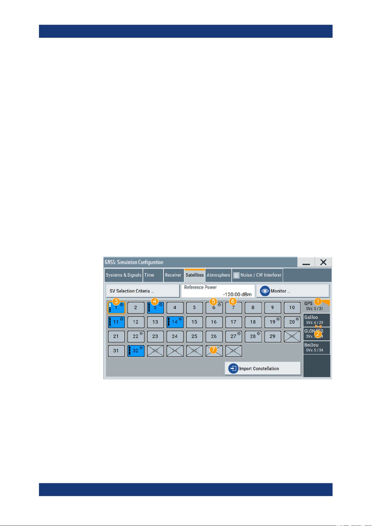
Remote command:
[:SOURce<hw>]:BB:GNSS:SYSTem:GPS:SIGNal:L1Band:CA[:STATe]
on page 320
[:SOURce<hw>]:BB:GNSS:SYSTem:GPS:SIGNal:L1Band:P[:STATe]
on page 320
(etc. for the other GNSS systems)
6.2 Satellites settings
Access:
1. Select "GNSS > Simulation Configuration > Satellites".
In the "Satellites" tab, you configure the satellites (SV ID) constellation for each
enabled GNSS system.
2. Select the GNSS system for that you want to configure satellites constellation.
Satellite constellationSatellite Navigation
Satellites settings
3. To configure individual settings per SV, like power offset, used signals and the content of the navigation message each satellites transmitts, select "SV# > SV Config".
For description, see Chapter 7, "Space vehicle configuration", on page 78.
In the "Satellite" dialog, you configure the satellite constellation.
Figure 6-1: Satellites constellation: Understanding the displayed information
1 = Enabled GNSS systems
2 = Number of active and available SVs per GNSS system
3 = Visible and active SV, that uses reduced power level
4 = Visible and active SV, full power level
5 = Visible and inactive SV ("Satellite's Constellation, SV ID" on page 75 = Off)
6 = Not visible and inactive SV
7 = Excluded from the constellation (Present in Constellation = "Off")
70User Manual 1178.6379.02 ─ 13

Satellite constellationSatellite Navigation
Satellites settings
The dialog consists of several tabs, one per activated GNSS System ("Systems&Signals > System > On").
Active and visible satellites are indicated with blue color.
The maximum number of the configurable satellites depends on the installed
options and can be set, see "SV Selection Criteria" on page 71.
Settings:
SV Selection Criteria.....................................................................................................71
└ Selection Mode............................................................................................... 71
└ Earth Obscuration References........................................................................72
└ Earth Obscuration Offset................................................................................ 74
└ Number of SVs > Min, Max, Current...............................................................74
└ Maximum Number of Channels/Total Number of Available Channels............ 74
Reference Power.......................................................................................................... 74
Simulation Monitor/Monitor........................................................................................... 75
Satellite's Constellation, SV ID......................................................................................75
└ State (SV ID)...................................................................................................76
└ Power Offset................................................................................................... 76
└ SV Config........................................................................................................76
Import Constellation...................................................................................................... 76
SV Selection Criteria
Access: "GNSS > Simulation Configuration > Satellites > SV Selection Criteria"
Opens the "SV Selection Criteria" dialog, where you set the minimum and maximum
number of satellites that can be activated per GNSS system and to set the satellites'
handover criteria.
Selection Mode ← SV Selection Criteria
Sets the criteria used to define the initial satellite constellation and rule applied by the
satellite's handover.
"Visibility Time"
Constellation consists of satellites that are likely to be visible for the
longest time.
71User Manual 1178.6379.02 ─ 13

Satellite constellationSatellite Navigation
Satellites settings
"Elevation Angle"
Selected are the satellites with the highest elevation.
Elevation is defined by the Earth Obscuration References and Earth
Obscuration Offset.
"Manual"
The automatic satellite's constellation configuration is deactivated.
Change the state of an SV ID to change the satellite constellation
manually. Any SV ID, incl. satellites that are currently invisible, can be
activated.
This mode is fixed and suspended for "Test Mode > Tracking" (Chap-
ter 9, "Tracking mode", on page 148).
Remote command:
[:SOURce<hw>]:BB:GNSS:SV:SELection:MODE on page 384
Earth Obscuration References ← SV Selection Criteria
Selects how the behavior of earth obscuration is defined. The behavior also defines the
horizon, which is the reference line for applying the elevation mask angle, see Fig-
ure 6-2.
Figure 6-2: Impact of the Earth Obscuration References on the area of visible satellites (XY cut)
A = "Local Horizon"
B = "Earth Tangent"
α
= "Earth Obscuration Offset" applied relative to the selected horizon
h = "Receiver > Positioning Configuration > Altitude"
r = Nadir (an imaginary vertical line that connects the location and the center of the earth)
1a = Horizon line for "Altitude = 0 m" (identical for both elevation mask types)
1b = Area of visible satellites (identical for both elevation mask types)
2a = Horizon line for "Altitude = h, km"; the horizon is parallel to the horizon with "Altitude = 0 m"
2b = Area of visible satellites
3a = Horizon lines for "Altitude = h, km"; the horizon lines are tangential to the earth surface
3b = Area of visible satellites
Use the "Signal Monitor" view to observe the current satellite constellation.
72User Manual 1178.6379.02 ─ 13

Satellite constellationSatellite Navigation
Satellites settings
This setting is not available for "Test Mode > Tracking" (Chapter 9, "Tracking mode",
on page 148).
The figures in Table 6-4 show the satellite constellations as seen by receiver at an "Alti-
tude = 200 km" with "Earth Obscuration Offset = 5°". The number of active satellites
changes because of the different elevation mask types.
Table 6-4: Impact of the Earth Obscuration References on the visible satellites
"Earth Obscuration References > Local Horizon" "Earth Obscuration References > Earth Tangent"
"Local Horizon"
The horizon is a horizontal plane that is perpendicular to the nadir.
For locations with attitudes above the sea level, the horizontal plane
is parallel shifted at the selected attitude.
The "Local Horizon" type is suitable, if you simulate receivers at low
altitude. For example, for pedestrian and automotive application.
"Earth Tangent"
The horizon is the surface of a right circular cone, where:
●
The vertex of the cone is at the receiver position.
●
The cone axis is along the nadir.
●
The cone surface is made of lines that are tangential to the earth
surface.
The "Earth Tangent" type is suitable, if you simulate receivers at
higher altitude, where satellites with negative elevations are also visible. A typical example is a GNSS receiver mounted on low earth orbit
(LEO) object.
Remote command:
[:SOURce<hw>]:BB:GNSS:SV:SELection:EOBScuration:REFerence
on page 384
73User Manual 1178.6379.02 ─ 13

Satellite constellationSatellite Navigation
Satellites settings
Earth Obscuration Offset ← SV Selection Criteria
Sets the satellite's elevation mask angle. The angle is applied relative to the selected
horizon, see "Earth Obscuration References" on page 72.
Satellites that are below the elevation mask angle are obscured. They are invisible for
the GNSS receiver at the selected location.
Obscured satellites are displayed in the "Signal Monitor" view but not simulated. A test
receiver cannot use obscured satellites for determining its position; it has to search for
satellites with better visibility.
See, for example, the figures in Table 6-4.
To ensure proper signal analysis, set the parameter "Earth Obscuration Offset" to the
elevation mask of the GNSS receiver under test.
This setting is not available for "Test Mode > Tracking" (Chapter 9, "Tracking mode",
on page 148).
Remote command:
[:SOURce<hw>]:BB:GNSS:SV:SELection:EOBScuration:ANGLe on page 385
Number of SVs > Min, Max, Current ← SV Selection Criteria
Sets the "Min" and "Max" number of satellites per GNSS system that can be included
in the satellite constellation.
"Current" indicates the number of active satellites per GNSS system that are currently
part of the satellite's constellation.
The displayed value resembles the overview information on the side tab of the "Satellites" dialog.
Remote command:
[:SOURce<hw>]:BB:GNSS:SV:SELection:GPS:MIN on page 385
[:SOURce<hw>]:BB:GNSS:SV:SELection:GPS:MAX on page 385
[:SOURce<hw>]:BB:GNSS:SV:SELection:GPS:ACTive? on page 386
see also [:SOURce<hw>]:BB:GNSS:SV:SELection:GPS:AVAilable?
on page 386
(etc. for the other GNSS systems)
Maximum Number of Channels/Total Number of Available Channels ← SV Selection Criteria
Requires R&S SMW-B9.
Displays the maximum/total number of channels. Editing the parameter requires "Mode
> GNSS Advanced".
The number depends on the simulation capacity, see Chapter G, "Channel budget",
on page 616.
Remote command:
[:SOURce<hw>]:BB:GNSS:SV:SELection:CHANnels:MAX on page 385
Reference Power
Sets the power level that is used as a reference for the calculation of the power level of
the satellites.
See "About satellite's (SV) power calculation" on page 78.
74User Manual 1178.6379.02 ─ 13

Satellite constellationSatellite Navigation
Satellites settings
Remote command:
[:SOURce<hw>]:BB:GNSS:POWer:REFerence on page 400
Simulation Monitor/Monitor
Accesses the "Simulation Monitor" dialog for real-time display of the major parameters,
like current satellite constellation with SV states and position, receiver position or
movement trajectory, or received satellite power.
See Chapter 3.3, "Simulation monitor", on page 34.
Satellite's Constellation, SV ID
Indicates the SV IDs included in the current constellation.
1
= Enabled GNSS systems
2 = Number of active and available SVs per GNSS system
3 = Visible and active SV, that uses reduced power level
4 = Visible and active SV, full power level
5 = Visible and inactive SV ("Satellite's Constellation, SV ID" on page 75 = Off)
6 = Not visible and inactive SV
7 = Excluded from the constellation (Present in Constellation = "Off")
The information is color-coded. Icons provide further information:
●
Blue: active SV ID
●
Gray: Inactive SV ID
●
Sun: Visible SV ID
●
Cross out: SV ID is excluded from the constellation, for example if "SV ID > SV
Config" > Present in Constellation > "Off"
●
Power bar: Reduced height indicates that the signal of the SV ID is transmitted with
less power than the value indicated as "Configurable Nav. Message".
The height of the power bar reflects enabled "Power Offset", "Power Path-Loss"
and "Power Offset" of the echoes.
The blocks are interactive. Select an SV ID to access further settings for changing its
state, enabling power offset of configuring the orbit simulation and navigation message
parameters.
75User Manual 1178.6379.02 ─ 13
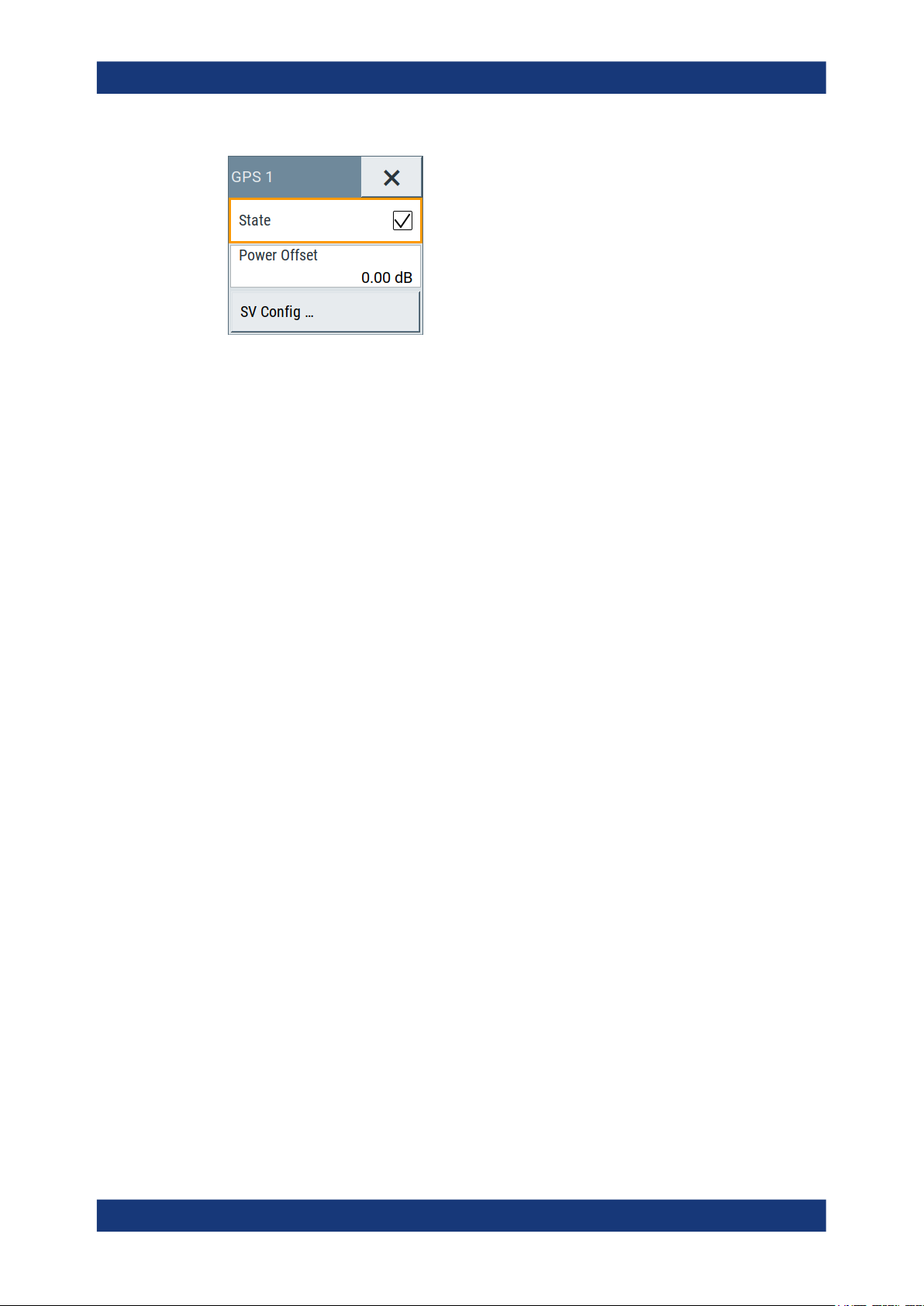
Satellite constellationSatellite Navigation
Satellites settings
Remote command:
[:SOURce<hw>]:BB:GNSS:SVID:GPS:LIST:ALL? on page 387
[:SOURce<hw>]:BB:GNSS:SVID:GPS:LIST[:VALid]? on page 387
[:SOURce<hw>]:BB:GNSS:SVID<ch>:GPS:HEALthy on page 387
[:SOURce<hw>]:BB:GNSS:SVID<ch>:GPS:VISibility:STATe? on page 388
(etc. for the other GNSS systems)
State (SV ID) ← Satellite's Constellation, SV ID
Changes the SV ID state on-the-fly.
Per default, only visible satellites can be included in the constellation. SV ID for that
Present in Constellation > "Off" cannot be activated.
Tip: Pressing the ON/OFF TOGGLE key has the same effect on the selected SV ID.
To enable any SV ID, set "Satellites > SV Selection Criteria > Selection Mode > Man-
ual".
Remote command:
[:SOURce<hw>]:BB:GNSS:SVID<ch>:GPS:STATe on page 399
(etc. for the other GNSS systems)
Power Offset ← Satellite's Constellation, SV ID
Reduces the signal of the selected SV ID by the defined value.
This is a global power offset parameter for a satellite. It affects the power level of all
signal components of a given satellite.
See "About satellite's (SV) power calculation" on page 78. Power changes are applied
on-the-fly.
Remote command:
[:SOURce<hw>]:BB:GNSS:SVID<ch>:GPS:POWer:OFFSet on page 401
(etc. for the other GNSS systems)
SV Config ← Satellite's Constellation, SV ID
Access a dialog with further settings for configuring the orbit simulation and navigation
message parameters.
See:
●
Chapter 7, "Space vehicle configuration", on page 78
●
Chapter 10, "Perturbations and errors simulation", on page 153
Import Constellation
Opens the "Import Constellation" dialog, that is a standard "File Select" dialog.
76User Manual 1178.6379.02 ─ 13

Satellite constellationSatellite Navigation
Satellites settings
You can select, e.g. almanac or RINEX files. See:
●
"Constellation data and navigation message file formats" on page 268.
●
Chapter 15.1, "Import GNSS constellation and navigation message data settings",
on page 270.
77User Manual 1178.6379.02 ─ 13

Space vehicle configurationSatellite Navigation
7 Space vehicle configuration
About satellite's (SV) power calculation
In R&S SMW, you define the power level of the individual satellites or their signals and
the power level at the RF output is calculated automatically. All power levels are set
relative to a configurable reference level. By changing this level you boost or
decrease the signal power at the R&S SMW outputs, while maintaining the power ratio
between the satellites, their signals and, if enabled, the multi-path echoes.
Absolute SV power
The absolute SV power for a given signal P
P
●
●
= P
SV,signal
P
Ref
P
SV,offset
+ P
Ref
is the reference power level, as set with the parameter Reference Power
is the global power offset of the satellite, as set with the parameter Power
SV,offset
+ P
Signal,offset
+ P
PathLoss
is calculated as follows:
SV,signal
+ P
AntPat
, where:
Offset
●
P
Signal,offset
is signal-specific power offset, as set with the parameter Signal Power
Offset
The value reflects the differences between the signals and the frequency bands.
●
P
is the free space path-loss over the satellite to receiver distance (range),
PathLoss
included if Add Power Path-Loss > "On".
See "Free space path-loss power" on page 78.
●
P
is the power gain of the antenna, calculated automatically, depending on the
AntPat
selected body mask
See Chapter 8.6, "Antenna and body mask settings", on page 121.
Free space path-loss power
P
is the free space path-loss over the satellite to receiver distance (range), cal-
PathLoss
culated as follows:
P
●
= 20log10(R0/R), where:
PathLoss
R0 = √(R
Orbit,SV
2
- r2)
R0 is the reference range, equal to the range of a receiver on the ground to an SV
at 90° elevation
●
R is the receiver to satellite range.
0
78User Manual 1178.6379.02 ─ 13

Figure 7-1: Free space path-loss calculation
SV0= Reference space vehicle
R0= Reference range
SV = Space vehicle
R = Range between the SV and the receiver
r = Earth's radius
Absolute multi-path echo power
Space vehicle configurationSatellite Navigation
Power settings
The absolute power of an echo for a given signal P
P
●
●
SV,echo
P
SV,signal
P
Echo,signal
= P
SV,signal
+ P
Echo,signal
, where:
is the absolute satellite's power
is the power offset per echo, as set with the parameter Power Offset.
is calculated as follows:
SV,echo
Satellite constellation recalculation
If you change settings of the space vehicle configuration, e.g., simulated orbit or simulated clock settings, the satellite constellation is recalculated accordingly. Recalculation
interrupts the simulation of the satellite constellation as long as the recalculation process takes.
During longer calculation times, the R&S SMW shows a "Busy" state.
Settings:
● Power settings.........................................................................................................79
● Modulation control settings..................................................................................... 84
● Simulated orbit and orbit perturbation settings........................................................89
● Simulated clock settings..........................................................................................98
7.1 Power settings
Access:
1. Select "GNSS > Simulation Configuration > Satellites".
2. Set the "Reference Power".
All power values are set relative to the reference power.
79User Manual 1178.6379.02 ─ 13

Space vehicle configurationSatellite Navigation
Power settings
3. Select the GNSS system for that you want to change the satellite's power settings,
for example GPS.
4. Select "SV# > SV Config".
5. In the "SV Configuration" dialog, select "Signals Configuration".
6. Select "Add Power Path-Loss > On" to account for the free-space attenuation.
7. Set a "Power Offset" to reduce further the signal power of the satellite.
8. In dual-band or multi-signal configurations, set a "Signal Power Offset" to account
for the power relation between the signals.
9. To apply the power settings of the current satellite to other SV ID, select for example "SV-ID = 11" and "Copy Power Settings To".
Figure 7-2: Power settings: understanding the displayed information
1 = Decreases the SV signal power and thus the power of all signals of this SV. SV "Power Offset" is
set relative to the Reference Power.
2 = Boosts or decreases the power of the individual signal components. Power offsets are set relative to
the Reference Power + "Power Offset".
Available power settings depend on the GNSS system and selected RF band.
For information on how these settings affect the SV power, see "About satellite's
(SV) power calculation" on page 78.
10. To simulate multi-path effects:
For more information, see Chapter 8.7.6, "Static multipath", on page 144.
a) Select "Simulation Configuration > Receiver > Environmental Model = Static
Multipath".
b) Select "Environmental Model"
c) Set for example: "Number of Echoes = 1", "Echo 1 > Init. Code Phase = 300
m", "Power Offset = -10 dB".
80User Manual 1178.6379.02 ─ 13

Space vehicle configurationSatellite Navigation
Power settings
11. Select "GNSS > Monitor > Satellites > Power View" to observe the power levels of
all satellites at a glance.
Figure 7-3: Power View: understanding the displayed information
R = Reference Power= -120 dB
1 = "SV ID 1 > Power Offset = -10 dB"
2 = "Signal Power Offsets", e.g. L1 C/A = 0 dB and L1 P = - 3dB; the same power relation is observed
SVs with or without power offset and for the multipath echoes
3 = "SV ID 1 > Echo 1 > Power Offset = -10 dB"
4 = One echo per signal ("Number of Echoes = 1"); displayed if "View Settings > Echoes = On"
12. Load and enable body mask files to visualize the effect of antennas on the power.
For more information, see Chapter 8.6, "Antenna and body mask settings",
on page 121.
The remote commands required to define these settings are described in:
● Chapter 19.11, "Signals and power configuration per satellite", on page 390
● Chapter 19.7, "Static multipath configuration", on page 358.
Settings:
State (SV ID).................................................................................................................81
Present in Constellation................................................................................................ 82
Healthy..........................................................................................................................82
Power Offset..................................................................................................................82
Add Power Path-Loss................................................................................................... 83
Frequency Number....................................................................................................... 83
SV signal configuration table.........................................................................................83
└ Signal Power Offset........................................................................................ 83
Copy Power Settings to,SV-ID......................................................................................83
State (SV ID)
Changes the SV ID state on-the-fly.
81User Manual 1178.6379.02 ─ 13

Space vehicle configurationSatellite Navigation
Power settings
Per default, only visible satellites can be included in the constellation. SV ID for that
Present in Constellation > "Off" cannot be activated.
Tip: Pressing the ON/OFF TOGGLE key has the same effect on the selected SV ID.
To enable any SV ID, set "Satellites > SV Selection Criteria > Selection Mode > Man-
ual".
Remote command:
[:SOURce<hw>]:BB:GNSS:SVID<ch>:GPS:STATe on page 399
(etc. for the other GNSS systems)
Present in Constellation
If disabled, the SV ID is excluded from the currents constellation. The SV ID is automatically deactivated ("SV ID > State = Off").
In the "Satellites" dialog, SV IDs that are excluded from the constellation are displayed
in gray color and are crossed out.
To reactivate such satellite, set "Present in Constellation > On" and activate it ("State >
On")
Remote command:
[:SOURce<hw>]:BB:GNSS:SVID<ch>:GPS:PRESent on page 399
(etc. for the other GNSS systems)
Healthy
Defines if the SV ID is healthy or not. A warning symbol indicates an unhealthy satellite.
The healthy state reflects the value of the corresponding healthy flag in the navigation
message. The healthy flag and the healthy state are interdependent; changing one of
them changes the other.
See:
●
GPS > Additional Data > "SV Health" and "L1/L2/L5 Health"
●
GLONASS > Additional Data > "SV Health"
●
Galileo > Additional Data > "E1B
●
BeiDou > Additional Data > "SV Health"
●
QZSS > Additional Data > "SV Health"
DVS
/E5b
/E1BHS/E5bHS"
DVS
Remote command:
[:SOURce<hw>]:BB:GNSS:SVID<ch>:GPS:HEALthy on page 387
(etc. for the other GNSS systems)
Power Offset
Reduces the signal of the selected SV ID by the defined value.
This is a global power offset parameter for a satellite. It affects the power level of all
signal components of a given satellite.
See "About satellite's (SV) power calculation" on page 78. Power changes are applied
on-the-fly.
Remote command:
[:SOURce<hw>]:BB:GNSS:SVID<ch>:GPS:POWer:OFFSet on page 401
(etc. for the other GNSS systems)
82User Manual 1178.6379.02 ─ 13

Space vehicle configurationSatellite Navigation
Power settings
Add Power Path-Loss
In "Test Mode = Navigation", enable this parameter to account for the free space
attenuation and simulate real-world conditions.
The power of the SV ID signals is reduced automatically. The power path-loss is calculated depending on the current satellite's orbit and the distance (range) between the
satellite and the receiver's position on the Earth, see "Free space path-loss power"
on page 78.
To observe the effect, select the "Monitor > Display > Power View", see Chapter 3.3,
"Simulation monitor", on page 34.
Remote command:
[:SOURce<hw>]:BB:GNSS:SVID<ch>:GPS:POWer:PLOSs on page 400
(etc. for the other GNSS systems)
Frequency Number
For GLONASS satellites, indicates the frequency number of the subcarrier used to
modulate the GLONASS satellite.
If "Nav Msg Type = NAV", the frequency number is retrieved from the imported configuration file.
The value is configurable, if arbitrary data is used, e.g. "Nav Msg Control > Edit" and
"Nav Msg Type > All 0".
Remote command:
[:SOURce<hw>]:BB:GNSS:SVID<ch>:GLONass:FNUMber on page 399
SV signal configuration table
Table with one or more rows, one row per enabled signal ("Simulation Configuration >
Systems&Signals" > Signals).
Signal Power Offset ← SV signal configuration table
Adds power offset for the selected signal.
If more than one signal or bands are activated, the power relation between the signals
and between the frequency bands is set automatically, as specified for the GNSS system. You can change these default values. Signal-specific power offset values are set
relative to the satellites power level.
See also "About satellite's (SV) power calculation" on page 78.
Remote command:
[:SOURce<hw>]:BB:GNSS:SVID<ch>:GPS:SIGNal:L1Band:CA:POWer:OFFset
on page 402
[:SOURce<hw>]:BB:GNSS:SVID<ch>:GPS:SIGNal:L1Band:P:POWer:OFFset
on page 402
(etc. for the other GNSS systems)
Copy Power Settings to,SV-ID
Applies the power settings of the current satellite to the selected or to all SV-IDs of the
same GNSS system.
The following settings are considered:
●
Power Offset
●
Add Power Path-Loss
83User Manual 1178.6379.02 ─ 13

●
Signal Power Offset
Remote command:
[:SOURce<hw>]:BB:GNSS:SVID<ch>:GPS:POWer:COPY:SVID on page 402
[:SOURce<hw>]:BB:GNSS:SVID<ch>:GPS:POWer:COPY:EXECute on page 403
(etc. for the other GNSS systems)
7.2 Modulation control settings
Access:
1. Select "GNSS > Simulation Configuration > Signals&Systems".
2. Enable the GNSS system for that you want to control the signal modulation, for
example:
a) "System > GLONASS > On"
b) "System > Galileo > On"
Space vehicle configurationSatellite Navigation
Modulation control settings
3. Select "GNSS > Simulation Configuration > Satellites".
4. Select "GLONASS > SV# > SV Config".
5. In the "SV Configuration" dialog, select "Signals Configuration".
6. To generate a signal with list mode data, sent on the GLONASS frequency, select:
a) "Primary Code > Off"
b) "Nav Msg Control > Edit"
c) "Nav Msg Type > Data List"
d) Load list mode data, e.g. from the file Glonass_Data.dm_iqd:
"Nav Msg Content > /var/user/Glonass_Data"
e) "Meander Sequence > Off"
f) "Time Sequence > Off"
84User Manual 1178.6379.02 ─ 13

Space vehicle configurationSatellite Navigation
Modulation control settings
7. To apply the modulation control settings of the current satellite to other SV ID,
select for example "SV-ID = All" and "Copy Modulation Control To"
Available modulation control settings depend on the GNSS system and selected
RF band.
The remote commands required to define these settings are described in Chap-
ter 19.11, "Signals and power configuration per satellite", on page 390.
Settings:
SV signal configuration table.........................................................................................85
└ Signal State.....................................................................................................85
└ Signal Component.......................................................................................... 86
└ Primary Code..................................................................................................86
└ Secondary Code............................................................................................. 86
└ Nav Msg Control............................................................................................. 86
└ Nav Msg Type.................................................................................................87
└ Nav Msg Content............................................................................................ 88
└ Meander Sequence.........................................................................................88
└ Time Sequence...............................................................................................89
Copy Modulation Control Settings to,SV-ID..................................................................89
SV signal configuration table
Table with one or more rows, one row per enabled signal ("Simulation Configuration >
Systems&Signals" > Signals).
Signal State ← SV signal configuration table
Activates the selected signal.
The available signals depend on GNSS system and the configuration in the Sys-
tems&Signals dialog.
At least one signal has to be activated per satellite. Activate another signal to deactivate a particular signal, if it is the only one active at that moment.
85User Manual 1178.6379.02 ─ 13

Space vehicle configurationSatellite Navigation
Modulation control settings
Remote command:
[:SOURce<hw>]:BB:GNSS:SVID<ch>:GPS:SIGNal:L1Band:CA[:STATe]
on page 404
[:SOURce<hw>]:BB:GNSS:SVID<ch>:GPS:SIGNal:L1Band:P[:STATe]
on page 404
(etc. for the other GNSS systems)
Signal Component ← SV signal configuration table
Indicates the signal content (data only or data and pilot).
The information is retrieved automatically from the selected simulation data source file.
Signal components depend on the signal, the frequency band and the GNSS system.
Remote command:
n.a.
Primary Code ← SV signal configuration table
Defines if the primary code is used to spread the data and pilot components.
If your interference tests require the generation of a continuous wave signal send on
the same frequency as a specific SV, set "Primary Code > Off" and "Nav Msg Control >
Off".
Remote command:
[:SOURce<hw>]:BB:GNSS:SVID<ch>:GPS:SIGNal:L1Band:CA:DATA:PCODe[:
STATe] on page 407
[:SOURce<hw>]:BB:GNSS:SVID<ch>:GPS:SIGNal:L1Band:CA:PILot:
PCODe[:STATe] on page 407
(etc. for the other GNSS systems)
Secondary Code ← SV signal configuration table
Enables the secondary code in the pilot and data channel of GPS, Galileo or BeiDou.
Remote command:
[:SOURce<hw>]:BB:GNSS:SVID<ch>:GPS:SIGNal:L1Band:L1C:PILot:
SCODe[:STATe] on page 408
[:SOURce<hw>]:BB:GNSS:SVID<ch>:GPS:SIGNal:L5Band:L5S:DATA:
SCODe[:STATe] on page 408
[:SOURce<hw>]:BB:GNSS:SVID<ch>:GPS:SIGNal:L5Band:L5S:PILot:
SCODe[:STATe] on page 408
(etc. for the other GNSS systems)
Nav Msg Control ← SV signal configuration table
Defines whether the navigation message parameters can be changed or not.
"Auto"
In Test Mode = "Navigation", the navigation message parameters are
adjusted automatically.
86User Manual 1178.6379.02 ─ 13

Space vehicle configurationSatellite Navigation
Modulation control settings
"On/Edit"
"Off"
Remote command:
"Test Mode = Navigation"
[:SOURce<hw>]:BB:GNSS:SVID<ch>:GPS:SIGNal:L1Band:CA:DATA:
NMESsage:CONTrol on page 409
[:SOURce<hw>]:BB:GNSS:SVID<ch>:GPS:SIGNal:L1Band:P:DATA:
NMESsage:CONTrol on page 409
"Test Mode = Tracking"
[:SOURce<hw>]:BB:GNSS:SVID<ch>:GPS:SIGNal:L1Band:CA:DATA:
NMESsage[:STATe] on page 522
[:SOURce<hw>]:BB:GNSS:SVID<ch>:GPS:SIGNal:L1Band:P:DATA:
NMESsage[:STATe] on page 522
(etc. for the other GNSS systems)
"On" requires "Test Mode > Navigation", "Edit" requires "Test Mode >
Tracking".
Enables configuration of the navigation message parameters ("Nav
Msg Type = xNav") or configuration of user-defined data ("Nav Msg
Type ≠ xNav").
Navigation message content of the SBAS SV is set automatically. To
enable the navigation message for configuration, set "Satellites" >
Error Correction Mode = "Replay Historical Data (and Sync Atmos-
phere& SV Errors)".
If "Satellites" > Error Correction Mode = "Replay Historical Data and
Sync Atmosphere& SV Errors", the navigation message content of all
other GNSS systems than SBAS is configured automatically. Editing
is not possible.
Navigation message is disabled.
A pure continuous-wave (CW) signal is output.
Nav Msg Type ← SV signal configuration table
Sets the data source used for the generation of the navigation message.
"LNAV/CNAV/FNAV/INAV/D1NAV/D2NAV/NAV"
The navigation message parameters are "real" since they are
retrieved from the loaded simulation data source file, see Import Con-
stellation.
"D1NAV" denotes navigation messages belonging to BeiDou
medium-altitude earth orbit (MEO) satellites (SV ID 6 to SV ID 35).
"D2NAV" denotes navigation messages belonging to BeiDou geostationary (GEO) satellites and inclined geostationary (IGSO) satellites
(SV ID 1 to SV ID 5).
Note: Galileo E6 signals carry no real navigation data. The signals
are simulated using data sources "PRBSxx/Data List/Pattern/Zero
NAV".
To change the automatically filled in values, select:
●
Nav Msg Control > "Edit"
●
Nav Msg Content > Config
87User Manual 1178.6379.02 ─ 13

"PRBSxx/Data List/Pattern"
Selects a configurable data source.
The data symbols from the data source are transmitted in the navigation message. The signal is sufficient for simple functional tests and
sensitivity tests.
The following standard data sources are available:
●
"All 0, All 1"
An internally generated sequence containing 0 data or 1 data.
●
"PNxx"
An internally generated pseudo-random noise sequence.
●
"Pattern"
An internally generated sequence according to a bit pattern.
Use the "Pattern" box to define the bit pattern.
●
"Data List/Select DList"
A binary data from a data list, internally or externally generated.
Select "Select DList" to access the standard "Select List" dialog.
– Select the "Select Data List > navigate to the list file *.dm_iqd
> Select" to select an existing data list.
– Use the "New" and "Edit" functions to create internally new
data list or to edit an existing one.
– Use the standard "File Manager" function to transfer external
data lists to the instrument.
See also:
●
Section "Modulation Data" in the R&S SMW user manual.
●
Section "File and Data Management" in the R&S SMW user manual.
●
Section "Data List Editor" in the R&S SMW user manual
Space vehicle configurationSatellite Navigation
Modulation control settings
"Zero NAV"
Remote command:
[:SOURce<hw>]:BB:GNSS:SVID<ch>:GPS:SIGNal:L1Band:CA:DATA:
NMESsage:TYPE on page 411
[:SOURce<hw>]:BB:GNSS:SVID<ch>:GPS:SIGNal:L1Band:CA:DATA:
NMESsage:DSELect on page 412
[:SOURce<hw>]:BB:GNSS:SVID<ch>:GPS:SIGNal:L1Band:CA:DATA:
NMESsage:PATTern on page 414
(etc. for the other GNSS systems)
Nav Msg Content ← SV signal configuration table
Opens the "Navigation Message" dialog, where you can observe the navigation message parameter and if enabled, change them.
See Chapter 10, "Perturbations and errors simulation", on page 153.
Meander Sequence ← SV signal configuration table
Enables meandering of GLONASS satellite navigation signals, i.e. doubling the data
rate.
Sets the broadcasted orbit and clock correction parameters in the
navigation message to zero. Frame structure, timing and channel
coding of the navigation message are retained.
88User Manual 1178.6379.02 ─ 13

Space vehicle configurationSatellite Navigation
Simulated orbit and orbit perturbation settings
Remote command:
[:SOURce<hw>]:BB:GNSS:SVID<ch>:GLONass:SIGNal:L1Band:CA:DATA:
MEANdering[:STATe] on page 414
[:SOURce<hw>]:BB:GNSS:SVID<ch>:GLONass:SIGNal:L2Band:CA:DATA:
MEANdering[:STATe] on page 414
Time Sequence ← SV signal configuration table
Enables the time signal component of GLONASS satellite navigation signals.
Remote command:
[:SOURce<hw>]:BB:GNSS:SVID<ch>:GLONass:SIGNal:L1Band:CA:DATA:
TSEQuence[:STATe] on page 414
[:SOURce<hw>]:BB:GNSS:SVID<ch>:GLONass:SIGNal:L2Band:CA:DATA:
TSEQuence[:STATe] on page 414
Copy Modulation Control Settings to,SV-ID
Applies the power settings of the current satellite to the selected or to all SV-IDs of the
same GNSS system.
The following settings are considered:
●
Signal State
●
Primary Code
●
Secondary Code
●
Nav Msg Control
●
Nav Msg Type
●
Meander Sequence
●
Time Sequence
Remote command:
[:SOURce<hw>]:BB:GNSS:SVID<ch>:GPS:MCONtrol:COPY:SVID on page 415
[:SOURce<hw>]:BB:GNSS:SVID<ch>:GPS:MCONtrol:COPY:EXECute
on page 416
(etc. for the other GNSS systems)
7.3 Simulated orbit and orbit perturbation settings
Access:
1. Select "GNSS > Simulation Configuration > Satellites".
2. Select the GNSS system for that you want to configure satellites constellation, for
example GPS.
3. Select "SV# > SV Config".
4. In the "SV Configuration" dialog, select "Simulated Orbit > Orbit" or "Simulated
Orbit > Orbit Perturbation".
Available navigation message parameters depend on the GNSS system.
89User Manual 1178.6379.02 ─ 13

Space vehicle configurationSatellite Navigation
Simulated orbit and orbit perturbation settings
Settings:
Ground Track................................................................................................................ 90
GPS SV.........................................................................................................................90
└ Simulated Orbit............................................................................................... 91
└ Orbit Perturbation............................................................................................91
Galileo SV..................................................................................................................... 92
└ Simulated Orbit............................................................................................... 92
└ Orbit Perturbation............................................................................................92
GLONASS SV...............................................................................................................93
└ Simulated Orbit............................................................................................... 93
BeiDou SV.....................................................................................................................94
└ Simulated Orbit............................................................................................... 94
└ Orbit Perturbation............................................................................................94
NavIC SV...................................................................................................................... 95
└ Simulated Orbit............................................................................................... 95
└ Orbit Perturbation............................................................................................96
QZSS SV.......................................................................................................................96
└ Simulated Orbit............................................................................................... 96
└ Orbit Perturbation............................................................................................97
└ NavIC SV........................................................................................................ 97
└ Simulated Orbit.....................................................................................97
└ Orbit Perturbation................................................................................. 98
Ground Track
Displays a plot of the trajectory of the selected satellite.
To observe the aggregated ground tracks of all satellites, select "GNSS > Simulation
Monitor > Display = Satellites > Ground Track".
GPS SV
Comprises the navigation message parameters, specific to and common for all GPS
satellites.
90User Manual 1178.6379.02 ─ 13

Space vehicle configurationSatellite Navigation
Simulated orbit and orbit perturbation settings
Simulated Orbit ← GPS SV
Comprises the navigation message parameters, specific to and common for all GPS
satellites.
Parameter Remote command:
"Reference Week" [:SOURce<hw>]:BB:GNSS:SVID<ch>:GPS:SIMulated:
ORBit:WNOE on page 433
"Reference Time of Week" [:SOURce<hw>]:BB:GNSS:SVID<ch>:GPS:SIMulated:
ORBit:TOE on page 434
1/2
"Square Root of Semi-Major Axis - A
"Eccentricity - e" [:SOURce<hw>]:BB:GNSS:SVID<ch>:GPS:SIMulated:
"Inclination Angle - i0" [:SOURce<hw>]:BB:GNSS:SVID<ch>:GPS:SIMulated:
"Longitude of Ascending Node - Ω0" [:SOURce<hw>]:BB:GNSS:SVID<ch>:GPS:SIMulated:
[:SOURce<hw>]:BB:GNSS:SVID<ch>:GPS:SIMulated:
"
ORBit:SQRA on page 435
ORBit:ECCentricity on page 435
ORBit:IZERo on page 436
ORBit:OZERo on page 436
"Argument of Perigee - ω" [:SOURce<hw>]:BB:GNSS:SVID<ch>:GPS:SIMulated:
ORBit:OMEGa on page 436
"Mean Anomaly - M0" [:SOURce<hw>]:BB:GNSS:SVID<ch>:GPS:SIMulated:
ORBit:MZERo on page 437
"Rate of Inclination Angle - i'" [:SOURce<hw>]:BB:GNSS:SVID<ch>:GPS:SIMulated:
ORBit:IDOT on page 437
"Rate of Right Ascension - Ω'" [:SOURce<hw>]:BB:GNSS:SVID<ch>:GPS:SIMulated:
ORBit:ODOT on page 437
"Mean Motion Difference - Δn" [:SOURce<hw>]:BB:GNSS:SVID<ch>:GPS:SIMulated:
ORBit:NDELta on page 438
Orbit Perturbation ← GPS SV
Comprises the navigation message parameters, specific to and common for all GPS
satellites.
Parameter Remote command:
"Cosine Difference of Latitude - Cuc" [:SOURce<hw>]:BB:GNSS:SVID<ch>:GPS:SIMulated:
ORBit:CUC on page 438
"Sine Difference of Latitude - Cus" [:SOURce<hw>]:BB:GNSS:SVID<ch>:GPS:SIMulated:
ORBit:CUS on page 438
"Cosine Difference of Orbital Radius - Crc" [:SOURce<hw>]:BB:GNSS:SVID<ch>:GPS:SIMulated:
ORBit:CRC on page 439
"Sine Difference of Orbital Radius - Crs" [:SOURce<hw>]:BB:GNSS:SVID<ch>:GPS:SIMulated:
ORBit:CRS on page 439
91User Manual 1178.6379.02 ─ 13

Space vehicle configurationSatellite Navigation
Simulated orbit and orbit perturbation settings
Parameter Remote command:
"Cosine Difference of Inclination - Cic" [:SOURce<hw>]:BB:GNSS:SVID<ch>:GPS:SIMulated:
ORBit:CIC on page 439
"Sine Difference of Inclination - Cis" [:SOURce<hw>]:BB:GNSS:SVID<ch>:GPS:SIMulated:
ORBit:CIS on page 439
Galileo SV
Comprises the navigation message parameters, specific to and common for all Galileo
satellites.
Simulated Orbit ← Galileo SV
Comprises the navigation message parameters, specific to and common for all Galileo
satellites.
Parameter Remote command:
"Reference Week" [:SOURce<hw>]:BB:GNSS:SVID<ch>:GALileo:
SIMulated:ORBit:WNOE on page 433
"Reference Time of Week" [:SOURce<hw>]:BB:GNSS:SVID<ch>:GALileo:
SIMulated:ORBit:TOE on page 434
1/2
"Square Root of Semi-Major Axis - A
"Eccentricity - e" [:SOURce<hw>]:BB:GNSS:SVID<ch>:GALileo:
"Inclination Angle - i0" [:SOURce<hw>]:BB:GNSS:SVID<ch>:GALileo:
"Longitude of Ascending Node - Ω0" [:SOURce<hw>]:BB:GNSS:SVID<ch>:GALileo:
"Argument of Perigee - ω" [:SOURce<hw>]:BB:GNSS:SVID<ch>:GALileo:
"Mean Anomaly - M0" [:SOURce<hw>]:BB:GNSS:SVID<ch>:GALileo:
"Rate of Inclination Angle - i'" [:SOURce<hw>]:BB:GNSS:SVID<ch>:GALileo:
"Rate of Right Ascension - Ω'" [:SOURce<hw>]:BB:GNSS:SVID<ch>:GALileo:
"Mean Motion Difference - Δn" [:SOURce<hw>]:BB:GNSS:SVID<ch>:GALileo:
[:SOURce<hw>]:BB:GNSS:SVID<ch>:GALileo:
"
SIMulated:ORBit:SQRA on page 435
SIMulated:ORBit:ECCentricity on page 435
SIMulated:ORBit:IZERo on page 436
SIMulated:ORBit:OZERo on page 436
SIMulated:ORBit:OMEGa on page 436
SIMulated:ORBit:MZERo on page 437
SIMulated:ORBit:IDOT on page 437
SIMulated:ORBit:ODOT on page 437
SIMulated:ORBit:NDELta on page 438
Orbit Perturbation ← Galileo SV
Comprises the navigation message parameters, specific to and common for all Galileo
satellites.
92User Manual 1178.6379.02 ─ 13

Space vehicle configurationSatellite Navigation
Simulated orbit and orbit perturbation settings
Parameter Remote command:
"Cosine Difference of Latitude - Cuc" [:SOURce<hw>]:BB:GNSS:SVID<ch>:GALileo:
SIMulated:ORBit:CUC on page 438
"Sine Difference of Latitude - Cus" [:SOURce<hw>]:BB:GNSS:SVID<ch>:GALileo:
SIMulated:ORBit:CUS on page 438
"Cosine Difference of Orbital Radius - Crc" [:SOURce<hw>]:BB:GNSS:SVID<ch>:GALileo:
SIMulated:ORBit:CRC on page 438
"Sine Difference of Orbital Radius - Crs" [:SOURce<hw>]:BB:GNSS:SVID<ch>:GALileo:
SIMulated:ORBit:CRS on page 439
"Cosine Difference of Inclination - Cic" [:SOURce<hw>]:BB:GNSS:SVID<ch>:GALileo:
SIMulated:ORBit:CIC on page 439
"Sine Difference of Inclination - Cis" [:SOURce<hw>]:BB:GNSS:SVID<ch>:GALileo:
SIMulated:ORBit:CIS on page 439
GLONASS SV
Comprises the navigation message parameters, specific to and common for all GLONASS satellites.
Simulated Orbit ← GLONASS SV
Comprises the navigation message parameters, specific to and common for all GLONASS satellites.
Parameter Remote command:
"Reference Date" [:SOURce<hw>]:BB:GNSS:SVID<ch>:GLONass:
SIMulated:ORBit:DATE on page 434
"Reference Time" [:SOURce<hw>]:BB:GNSS:SVID<ch>:GLONass:
SIMulated:ORBit:TIME on page 435
"Xn" [:SOURce<hw>]:BB:GNSS:SVID<ch>:GLONass:
SIMulated:ORBit:XN on page 432
"Yn" [:SOURce<hw>]:BB:GNSS:SVID<ch>:GLONass:
SIMulated:ORBit:YN on page 432
"Zn" [:SOURce<hw>]:BB:GNSS:SVID<ch>:GLONass:
SIMulated:ORBit:ZN on page 432
"X'n" [:SOURce<hw>]:BB:GNSS:SVID<ch>:GLONass:
SIMulated:ORBit:XDN on page 433
"Y'n" [:SOURce<hw>]:BB:GNSS:SVID<ch>:GLONass:
SIMulated:ORBit:YDN on page 433
"Z'n" [:SOURce<hw>]:BB:GNSS:SVID<ch>:GLONass:
SIMulated:ORBit:ZDN on page 433
"X''n" [:SOURce<hw>]:BB:GNSS:SVID<ch>:GLONass:
SIMulated:ORBit:XDDN on page 433
93User Manual 1178.6379.02 ─ 13

Space vehicle configurationSatellite Navigation
Simulated orbit and orbit perturbation settings
Parameter Remote command:
"Y''n" [:SOURce<hw>]:BB:GNSS:SVID<ch>:GLONass:
SIMulated:ORBit:YDDN on page 433
"Z''n" [:SOURce<hw>]:BB:GNSS:SVID<ch>:GLONass:
SIMulated:ORBit:ZDDN on page 433
BeiDou SV
Comprises the navigation message parameters, specific to and common for all BeiDou
satellites.
Simulated Orbit ← BeiDou SV
Comprises the navigation message parameters, specific to and common for all BeiDou
satellites.
Parameter Remote command:
"Reference Week" [:SOURce<hw>]:BB:GNSS:SVID<ch>:BEIDou:
SIMulated:ORBit:WNOE on page 433
"Reference Time of Week" [:SOURce<hw>]:BB:GNSS:SVID<ch>:BEIDou:
SIMulated:ORBit:TOE on page 434
1/2
"Square Root of Semi-Major Axis - A
"Eccentricity - e" [:SOURce<hw>]:BB:GNSS:SVID<ch>:BEIDou:
"Inclination Angle - i0" [:SOURce<hw>]:BB:GNSS:SVID<ch>:BEIDou:
"Longitude of Ascending Node - Ω0" [:SOURce<hw>]:BB:GNSS:SVID<ch>:BEIDou:
"Argument of Perigee - ω" [:SOURce<hw>]:BB:GNSS:SVID<ch>:BEIDou:
"Mean Anomaly - M0" [:SOURce<hw>]:BB:GNSS:SVID<ch>:BEIDou:
"Rate of Inclination Angle - i'" [:SOURce<hw>]:BB:GNSS:SVID<ch>:BEIDou:
"Rate of Right Ascension - Ω'" [:SOURce<hw>]:BB:GNSS:SVID<ch>:BEIDou:
"Mean Motion Difference - Δn" [:SOURce<hw>]:BB:GNSS:SVID<ch>:BEIDou:
[:SOURce<hw>]:BB:GNSS:SVID<ch>:BEIDou:
"
SIMulated:ORBit:SQRA on page 435
SIMulated:ORBit:ECCentricity on page 435
SIMulated:ORBit:IZERo on page 436
SIMulated:ORBit:OZERo on page 436
SIMulated:ORBit:OMEGa on page 436
SIMulated:ORBit:MZERo on page 437
SIMulated:ORBit:IDOT on page 437
SIMulated:ORBit:ODOT on page 437
SIMulated:ORBit:NDELta on page 438
Orbit Perturbation ← BeiDou SV
Comprises the navigation message parameters, specific to and common for all BeiDou
satellites.
94User Manual 1178.6379.02 ─ 13

Space vehicle configurationSatellite Navigation
Simulated orbit and orbit perturbation settings
Parameter Remote command:
"Cosine Difference of Latitude - Cuc" [:SOURce<hw>]:BB:GNSS:SVID<ch>:BEIDou:
SIMulated:ORBit:CUC on page 438
"Sine Difference of Latitude - Cus" [:SOURce<hw>]:BB:GNSS:SVID<ch>:BEIDou:
SIMulated:ORBit:CUS on page 438
"Cosine Difference of Orbital Radius - Crc" [:SOURce<hw>]:BB:GNSS:SVID<ch>:BEIDou:
SIMulated:ORBit:CRC on page 439
"Sine Difference of Orbital Radius - Crs" [:SOURce<hw>]:BB:GNSS:SVID<ch>:BEIDou:
SIMulated:ORBit:CRS on page 439
"Cosine Difference of Inclination - Cic" [:SOURce<hw>]:BB:GNSS:SVID<ch>:BEIDou:
SIMulated:ORBit:CIC on page 439
"Sine Difference of Inclination - Cis" [:SOURce<hw>]:BB:GNSS:SVID<ch>:BEIDou:
SIMulated:ORBit:CIS on page 439
NavIC SV
Comprises the navigation message parameters, specific to and common for all NavIC
satellites.
Simulated Orbit ← NavIC SV
Comprises the navigation message parameters, specific to and common for all BeiDou
satellites.
Parameter Remote command:
"Reference Week" [:SOURce<hw>]:BB:GNSS:SVID<ch>:BEIDou:
SIMulated:ORBit:WNOE on page 433
"Reference Time of Week" [:SOURce<hw>]:BB:GNSS:SVID<ch>:BEIDou:
SIMulated:ORBit:TOE on page 434
1/2
"Square Root of Semi-Major Axis - A
"Eccentricity - e" [:SOURce<hw>]:BB:GNSS:SVID<ch>:BEIDou:
"Inclination Angle - i0" [:SOURce<hw>]:BB:GNSS:SVID<ch>:BEIDou:
"Longitude of Ascending Node - Ω0" [:SOURce<hw>]:BB:GNSS:SVID<ch>:BEIDou:
"Argument of Perigee - ω" [:SOURce<hw>]:BB:GNSS:SVID<ch>:BEIDou:
"Mean Anomaly - M0" [:SOURce<hw>]:BB:GNSS:SVID<ch>:BEIDou:
[:SOURce<hw>]:BB:GNSS:SVID<ch>:BEIDou:
"
SIMulated:ORBit:SQRA on page 435
SIMulated:ORBit:ECCentricity on page 435
SIMulated:ORBit:IZERo on page 436
SIMulated:ORBit:OZERo on page 436
SIMulated:ORBit:OMEGa on page 436
SIMulated:ORBit:MZERo on page 437
"Rate of Inclination Angle - i'" [:SOURce<hw>]:BB:GNSS:SVID<ch>:BEIDou:
SIMulated:ORBit:IDOT on page 437
95User Manual 1178.6379.02 ─ 13

Space vehicle configurationSatellite Navigation
Simulated orbit and orbit perturbation settings
Parameter Remote command:
"Rate of Right Ascension - Ω'" [:SOURce<hw>]:BB:GNSS:SVID<ch>:BEIDou:
SIMulated:ORBit:ODOT on page 437
"Mean Motion Difference - Δn" [:SOURce<hw>]:BB:GNSS:SVID<ch>:BEIDou:
SIMulated:ORBit:NDELta on page 438
Orbit Perturbation ← NavIC SV
Comprises the navigation message parameters, specific to and common for all BeiDou
satellites.
Parameter Remote command:
"Cosine Difference of Latitude - Cuc" [:SOURce<hw>]:BB:GNSS:SVID<ch>:BEIDou:
SIMulated:ORBit:CUC on page 438
"Sine Difference of Latitude - Cus" [:SOURce<hw>]:BB:GNSS:SVID<ch>:BEIDou:
SIMulated:ORBit:CUS on page 438
"Cosine Difference of Orbital Radius - Crc" [:SOURce<hw>]:BB:GNSS:SVID<ch>:BEIDou:
SIMulated:ORBit:CRC on page 439
"Sine Difference of Orbital Radius - Crs" [:SOURce<hw>]:BB:GNSS:SVID<ch>:BEIDou:
SIMulated:ORBit:CRS on page 439
"Cosine Difference of Inclination - Cic" [:SOURce<hw>]:BB:GNSS:SVID<ch>:BEIDou:
SIMulated:ORBit:CIC on page 439
"Sine Difference of Inclination - Cis" [:SOURce<hw>]:BB:GNSS:SVID<ch>:BEIDou:
SIMulated:ORBit:CIS on page 439
QZSS SV
Comprises the navigation message parameters, specific to and common for all QZSS
satellites.
Simulated Orbit ← QZSS SV
Comprises the navigation message parameters, specific to and common for all QZSS
satellites.
Parameter Remote command:
"Reference Week" [:SOURce<hw>]:BB:GNSS:SVID<ch>:QZSS:SIMulated:
ORBit:WNOE on page 433
"Reference Time of Week" [:SOURce<hw>]:BB:GNSS:SVID<ch>:QZSS:SIMulated:
ORBit:TOE on page 434
1/2
"Square Root of Semi-Major Axis - A
[:SOURce<hw>]:BB:GNSS:SVID<ch>:QZSS:SIMulated:
"
ORBit:SQRA on page 435
"Eccentricity - e" [:SOURce<hw>]:BB:GNSS:SVID<ch>:QZSS:SIMulated:
ORBit:ECCentricity on page 435
"Inclination Angle - i0" [:SOURce<hw>]:BB:GNSS:SVID<ch>:QZSS:SIMulated:
ORBit:IZERo on page 436
"Longitude of Ascending Node - Ω0" [:SOURce<hw>]:BB:GNSS:SVID<ch>:QZSS:SIMulated:
ORBit:OZERo on page 436
96User Manual 1178.6379.02 ─ 13

Space vehicle configurationSatellite Navigation
Simulated orbit and orbit perturbation settings
Parameter Remote command:
"Argument of Perigee - ω" [:SOURce<hw>]:BB:GNSS:SVID<ch>:QZSS:SIMulated:
ORBit:OMEGa on page 436
"Mean Anomaly - M0" [:SOURce<hw>]:BB:GNSS:SVID<ch>:QZSS:SIMulated:
ORBit:MZERo on page 437
"Rate of Inclination Angle - i'" [:SOURce<hw>]:BB:GNSS:SVID<ch>:QZSS:SIMulated:
ORBit:IDOT on page 437
"Rate of Right Ascension - Ω'" [:SOURce<hw>]:BB:GNSS:SVID<ch>:QZSS:SIMulated:
ORBit:ODOT on page 437
"Mean Motion Difference - Δn" [:SOURce<hw>]:BB:GNSS:SVID<ch>:QZSS:SIMulated:
ORBit:NDELta on page 438
Orbit Perturbation ← QZSS SV
Comprises the navigation message parameters, specific to and common for all QZSS
satellites.
Parameter Remote command:
"Cosine Difference of Latitude - Cuc" [:SOURce<hw>]:BB:GNSS:SVID<ch>:QZSS:SIMulated:
ORBit:CUC on page 438
"Sine Difference of Latitude - Cus" [:SOURce<hw>]:BB:GNSS:SVID<ch>:QZSS:SIMulated:
ORBit:CUS on page 438
"Cosine Difference of Orbital Radius - Crc" [:SOURce<hw>]:BB:GNSS:SVID<ch>:QZSS:SIMulated:
ORBit:CRC on page 438
"Sine Difference of Orbital Radius - Crs" [:SOURce<hw>]:BB:GNSS:SVID<ch>:QZSS:SIMulated:
ORBit:CRS on page 439
"Cosine Difference of Inclination - Cic" [:SOURce<hw>]:BB:GNSS:SVID<ch>:QZSS:SIMulated:
ORBit:CIC on page 439
"Sine Difference of Inclination - Cis" [:SOURce<hw>]:BB:GNSS:SVID<ch>:QZSS:SIMulated:
ORBit:CIS on page 439
NavIC SV ← QZSS SV
Comprises the navigation message parameters, specific to and common for all NavIC
satellites.
Simulated Orbit ← NavIC SV ← QZSS SV
Comprises the navigation message parameters, specific to and common for all NavIC
satellites.
Parameter Remote command:
"Reference Week" [:SOURce<hw>]:BB:GNSS:SVID<ch>:NAVic:
SIMulated:ORBit:WNOE on page 433
"Reference Time of Week" [:SOURce<hw>]:BB:GNSS:SVID<ch>:NAVic:
SIMulated:ORBit:TOE on page 434
1/2
"Square Root of Semi-Major Axis - A
[:SOURce<hw>]:BB:GNSS:SVID<ch>:NAVic:
"
SIMulated:ORBit:SQRA on page 435
97User Manual 1178.6379.02 ─ 13

Space vehicle configurationSatellite Navigation
Simulated clock settings
Parameter Remote command:
"Eccentricity - e" [:SOURce<hw>]:BB:GNSS:SVID<ch>:NAVic:
SIMulated:ORBit:ECCentricity on page 435
"Inclination Angle - i0" [:SOURce<hw>]:BB:GNSS:SVID<ch>:NAVic:
SIMulated:ORBit:IZERo on page 436
"Longitude of Ascending Node - Ω0" [:SOURce<hw>]:BB:GNSS:SVID<ch>:NAVic:
SIMulated:ORBit:OZERo on page 436
"Argument of Perigee - ω" [:SOURce<hw>]:BB:GNSS:SVID<ch>:NAVic:
SIMulated:ORBit:OMEGa on page 436
"Mean Anomaly - M0" [:SOURce<hw>]:BB:GNSS:SVID<ch>:NAVic:
SIMulated:ORBit:MZERo on page 437
"Rate of Inclination Angle - i'" [:SOURce<hw>]:BB:GNSS:SVID<ch>:NAVic:
SIMulated:ORBit:IDOT on page 437
"Rate of Right Ascension - Ω'" [:SOURce<hw>]:BB:GNSS:SVID<ch>:NAVic:
SIMulated:ORBit:ODOT on page 437
"Mean Motion Difference - Δn" [:SOURce<hw>]:BB:GNSS:SVID<ch>:NAVic:
SIMulated:ORBit:NDELta on page 438
Orbit Perturbation ← NavIC SV ← QZSS SV
Comprises the navigation message parameters, specific to and common for all NavIC
satellites.
Parameter Remote command:
"Cosine Difference of Latitude - Cuc" [:SOURce<hw>]:BB:GNSS:SVID<ch>:NAVic:
SIMulated:ORBit:CUC on page 438
"Sine Difference of Latitude - Cus" [:SOURce<hw>]:BB:GNSS:SVID<ch>:NAVic:
SIMulated:ORBit:CUS on page 438
"Cosine Difference of Orbital Radius - Crc" [:SOURce<hw>]:BB:GNSS:SVID<ch>:NAVic:
SIMulated:ORBit:CRC on page 438
"Sine Difference of Orbital Radius - Crs" [:SOURce<hw>]:BB:GNSS:SVID<ch>:NAVic:
SIMulated:ORBit:CRS on page 439
"Cosine Difference of Inclination - Cic" [:SOURce<hw>]:BB:GNSS:SVID<ch>:NAVic:
SIMulated:ORBit:CIC on page 439
"Sine Difference of Inclination - Cis" [:SOURce<hw>]:BB:GNSS:SVID<ch>:NAVic:
SIMulated:ORBit:CIS on page 439
7.4 Simulated clock settings
Access:
1. Select "GNSS > Simulation Configuration > Satellites".
98User Manual 1178.6379.02 ─ 13

Space vehicle configurationSatellite Navigation
Simulated clock settings
2. Select the GNSS system for that you want to configure satellites constellation, for
example GPS.
3. Select "SV# > SV Config".
4. In the "SV Configuration" dialog, select "Simulated Clock".
Available navigation message parameters depend on the GNSS system.
Settings:
GPS > Simulated Clock.................................................................................................99
Galileo > Simulated Clock.............................................................................................99
GLONASS > Simulated Clock.....................................................................................100
BeiDou > Simulated Clock.......................................................................................... 100
QZSS > Simulated Clock............................................................................................ 100
NavIC > Simulated Clock............................................................................................ 101
GPS > Simulated Clock
Comprises the navigation message parameters, specific to and common for all GPS
satellites.
Parameter Remote command:
"Reference Week" [:SOURce<hw>]:BB:GNSS:SVID<ch>:GPS:SIMulated:
CLOCk:WNOC on page 440
"Reference Time of Week" [:SOURce<hw>]:BB:GNSS:SVID<ch>:GPS:SIMulated:
CLOCk:TOC on page 440
"af0 - af2" [:SOURce<hw>]:BB:GNSS:SVID<ch>:GPS:SIMulated:
CLOCk:AF<s2us0> on page 440
"Group Delay - Tgd" [:SOURce<hw>]:BB:GNSS:SVID<ch>:GPS:SIMulated:
CLOCk:TGD on page 441
Galileo > Simulated Clock
Comprises the navigation message parameters, specific to and common for all Galileo
satellites.
99User Manual 1178.6379.02 ─ 13

Space vehicle configurationSatellite Navigation
Simulated clock settings
Parameter Remote command:
"Reference Week" [:SOURce<hw>]:BB:GNSS:SVID<ch>:GALileo:
SIMulated:CLOCk:WNOC on page 440
"Time of Clock - t0c (E1-E5B)" [:SOURce<hw>]:BB:GNSS:SVID<ch>:GALileo:
SIMulated:CLOCk:TOC on page 440
"af0 (E1-E5B)" to "af2 (E1-E5B)" [:SOURce<hw>]:BB:GNSS:SVID<ch>:GALileo:
SIMulated:CLOCk:AF<s2us0> on page 440
"Group Delay - BGD (E1-E5B)" [:SOURce<hw>]:BB:GNSS:SVID<ch>:GALileo:
SIMulated:CLOCk:TGD on page 441
GLONASS > Simulated Clock
Comprises the navigation message parameters, specific to and common for all GLONASS satellites.
Parameter Remote command:
"Reference Date" [:SOURce<hw>]:BB:GNSS:SVID<ch>:GLONass:
SIMulated:CLOCk:DATE on page 434
"Reference Time" [:SOURce<hw>]:BB:GNSS:SVID<ch>:GLONass:
SIMulated:CLOCk:TIME on page 435
"af0" to "af2" [:SOURce<hw>]:BB:GNSS:SVID<ch>:GLONass:
SIMulated:CLOCk:AF<s2us0> on page 440
"Group Delay - Tgd" [:SOURce<hw>]:BB:GNSS:SVID<ch>:GLONass:
SIMulated:CLOCk:TGD on page 441
BeiDou > Simulated Clock
Comprises the navigation message parameters, specific to and common for all BeiDou
satellites.
Parameter Remote command:
"Reference Week" [:SOURce<hw>]:BB:GNSS:SVID<ch>:BEIDou:
SIMulated:CLOCk:WNOC on page 440
"Reference Time of Week" [:SOURce<hw>]:BB:GNSS:SVID<ch>:BEIDou:
SIMulated:CLOCk:TOC on page 440
"af0" to "af2" [:SOURce<hw>]:BB:GNSS:SVID<ch>:BEIDou:
SIMulated:CLOCk:AF<s2us0> on page 440
"Group Delay B1I - T
"Group Delay B2I - T
GD1
GD2
"
"
[:SOURce<hw>]:BB:GNSS:SVID<ch>:BEIDou:
PRERrors:MODE on page 443
QZSS > Simulated Clock
Comprises the navigation message parameters, specific to and common for all QZSS
satellites.
100User Manual 1178.6379.02 ─ 13
 Loading...