

Page 1

R&S®SMW-K551
Generation of Digital "Slow IQ"
Signals
User Manual
(;ÚíÎ2)
1176956402
User Manual
Version 12
Page 2

This document describes the following software options:
●
R&S®SMW-K551
1413.9724.xx
This manual describes firmware version FW 4.70.026.xx and later of the R&S®SMW200A.
© 2019 Rohde & Schwarz GmbH & Co. KG
Mühldorfstr. 15, 81671 München, Germany
Phone: +49 89 41 29 - 0
Fax: +49 89 41 29 12 164
Email: info@rohde-schwarz.com
Internet: www.rohde-schwarz.com
Subject to change – Data without tolerance limits is not binding.
R&S® is a registered trademark of Rohde & Schwarz GmbH & Co. KG.
Trade names are trademarks of the owners.
1176.9564.02 | Version 12 | R&S®SMW-K551
The following abbreviations are used throughout this manual: R&S®SMW200A is abbreviated as R&S SMW, R&S®EX-IQ-BOX is
abbreviated as R&S EX-IQ-BOX, R&S®DigIConf is abbreviated as R&S DigIConf; the license types 02/03/07/11/13/16/12 are abbre-
viated as xx.
Page 3

R&S®SMW-K551
1 Preface.................................................................................................... 5
1.1 About this Manual......................................................................................................... 5
1.2 Documentation Overview............................................................................................. 5
1.2.1 Getting Started Manual................................................................................................... 6
1.2.2 User Manuals and Help...................................................................................................6
1.2.3 Tutorials...........................................................................................................................6
1.2.4 Service Manual............................................................................................................... 6
1.2.5 Instrument Security Procedures......................................................................................6
1.2.6 Basic Safety Instructions.................................................................................................7
1.2.7 Data Sheets and Brochures............................................................................................ 7
1.2.8 Release Notes and Open Source Acknowledgment (OSA)............................................ 7
Contents
Contents
1.2.9 Application Notes, Application Cards, White Papers, etc................................................7
1.3 Conventions Used in the Documentation...................................................................7
1.3.1 Typographical Conventions.............................................................................................7
1.3.2 Conventions for Procedure Descriptions.........................................................................8
1.3.3 Notes on Screenshots.....................................................................................................8
2 Welcome to the R&S SMW-K551 Option..............................................9
2.1 Accessing the Slow IQ Settings.................................................................................. 9
2.2 Scope........................................................................................................................... 10
3 About the Slow IQ Signal Generation.................................................11
3.1 Required Options and Equipment............................................................................. 11
3.2 Principle of Generation of Signals with Reduced Speed........................................ 12
3.3 Transmission Modes...................................................................................................13
3.4 Default Stream Mapping............................................................................................. 16
3.4.1 Limitations and Interdependencies with Other Parameters.......................................... 17
3.5 Synchronization Issues.............................................................................................. 18
4 Slow IQ Related Settings.....................................................................19
5 How To Generate Signals with Reduced Speed for FPGA Tests..... 24
6 Remote Control Commands................................................................30
3User Manual 1176.9564.02 ─ 12
Page 4

R&S®SMW-K551
7 Further Information..............................................................................31
Contents
List of Commands................................................................................32
Index......................................................................................................33
4User Manual 1176.9564.02 ─ 12
Page 5

R&S®SMW-K551
1 Preface
1.1 About this Manual
Preface
Documentation Overview
This User Manual provides all the information specific to the options R&S SMW-
K551. All general instrument functions and settings common to all applications and
operating modes are described in the main R&S SMW user manual.
The main focus in this manual is on the provided settings and the tasks required to
generate a signal. The following topics are included:
●
Welcome to the Slow IQ option R&S SMW-K551
Introduction to and getting familiar with the option
●
About the Slow IQ Signal Generation
Background information on basic terms and principles in the context of the signal
generation
●
Configuration and Settings
A concise description of all functions and settings available to configure signal generation with their corresponding remote control command
●
How To Generate Signals with Reduced Speed for FPGA Tests
The basic procedure to perform signal generation tasks and step-by-step instructions for more complex tasks or alternative methods
As well as detailed examples to guide you through typical signal generation scenarios and allow you to try out the application immediately
●
Remote Control Commands
Remote commands required to configure and perform signal generation in a
remote environment, sorted by tasks
(Commands required to set up the instrument or to perform common tasks on the
instrument are provided in the main R&S SMW user manual)
Programming examples demonstrate the use of many commands and can usually
be executed directly for test purposes
●
List of remote commands
Alphabetical list of all remote commands described in the manual
●
Index
1.2 Documentation Overview
This section provides an overview of the R&S SMW user documentation. Unless specified otherwise, you find the documents on the R&S SMW product page at:
www.rohde-schwarz.com/manual/smw200a
5User Manual 1176.9564.02 ─ 12
Page 6

R&S®SMW-K551
1.2.1 Getting Started Manual
1.2.2 User Manuals and Help
Preface
Documentation Overview
Introduces the R&S SMW and describes how to set up and start working with the product. Includes basic operations, typical measurement examples, and general information, e.g. safety instructions, etc. A printed version is delivered with the instrument.
Separate manuals for the base unit and the software options are provided for download:
●
Base unit manual
Contains the description of all instrument modes and functions. It also provides an
introduction to remote control, a complete description of the remote control commands with programming examples, and information on maintenance, instrument
interfaces and error messages. Includes the contents of the getting started manual.
●
Software option manual
Contains the description of the specific functions of an option. Basic information on
operating the R&S SMW is not included.
The contents of the user manuals are available as help in the R&S SMW. The help
offers quick, context-sensitive access to the complete information for the base unit and
the software options.
All user manuals are also available for download or for immediate display on the Internet.
1.2.3 Tutorials
The R&S SMW provides interactive examples and demonstrations on operating the
instrument in form of tutorials. A set of tutorials is available directly on the instrument.
1.2.4 Service Manual
Describes the performance test for checking the rated specifications, module replacement and repair, firmware update, troubleshooting and fault elimination, and contains
mechanical drawings and spare part lists.
The service manual is available for registered users on the global Rohde & Schwarz
information system (GLORIS, https://gloris.rohde-schwarz.com).
1.2.5 Instrument Security Procedures
Deals with security issues when working with the R&S SMW in secure areas. It is available for download on the Internet.
6User Manual 1176.9564.02 ─ 12
Page 7

R&S®SMW-K551
1.2.6 Basic Safety Instructions
1.2.7 Data Sheets and Brochures
1.2.8 Release Notes and Open Source Acknowledgment (OSA)
Preface
Conventions Used in the Documentation
Contains safety instructions, operating conditions and further important information.
The printed document is delivered with the instrument.
The data sheet contains the technical specifications of the R&S SMW. It also lists the
options and their order numbers and optional accessories.
The brochure provides an overview of the instrument and deals with the specific characteristics.
See www.rohde-schwarz.com/brochure-datasheet/smw200a
The release notes list new features, improvements and known issues of the current
firmware version, and describe the firmware installation.
The open source acknowledgment document provides verbatim license texts of the
used open source software.
See www.rohde-schwarz.com/firmware/smw200a
1.2.9 Application Notes, Application Cards, White Papers, etc.
These documents deal with special applications or background information on particular topics.
See www.rohde-schwarz.com/application/smw200a and www.rohde-schwarz.com/
manual/smw200a
1.3 Conventions Used in the Documentation
1.3.1 Typographical Conventions
The following text markers are used throughout this documentation:
Convention Description
"Graphical user interface elements"
[Keys] Key and knob names are enclosed by square brackets.
All names of graphical user interface elements on the screen, such as
dialog boxes, menus, options, buttons, and softkeys are enclosed by
quotation marks.
7User Manual 1176.9564.02 ─ 12
Page 8

R&S®SMW-K551
Preface
Conventions Used in the Documentation
Convention Description
Filenames, commands,
program code
Input Input to be entered by the user is displayed in italics.
Links Links that you can click are displayed in blue font.
"References" References to other parts of the documentation are enclosed by quota-
Filenames, commands, coding samples and screen output are distinguished by their font.
tion marks.
1.3.2 Conventions for Procedure Descriptions
When operating the instrument, several alternative methods may be available to perform the same task. In this case, the procedure using the touchscreen is described.
Any elements that can be activated by touching can also be clicked using an additionally connected mouse. The alternative procedure using the keys on the instrument or
the on-screen keyboard is only described if it deviates from the standard operating procedures.
The term "select" may refer to any of the described methods, i.e. using a finger on the
touchscreen, a mouse pointer in the display, or a key on the instrument or on a keyboard.
1.3.3 Notes on Screenshots
When describing the functions of the product, we use sample screenshots. These
screenshots are meant to illustrate as many as possible of the provided functions and
possible interdependencies between parameters. The shown values may not represent
realistic usage scenarios.
The screenshots usually show a fully equipped product, that is: with all options installed. Thus, some functions shown in the screenshots may not be available in your particular product configuration.
8User Manual 1176.9564.02 ─ 12
Page 9

R&S®SMW-K551
2 Welcome to the R&S SMW-K551 Option
Welcome to the R&S SMW-K551 Option
Accessing the Slow IQ Settings
The R&S SMW-K551 is a software option that allows you to generate digital signals
with reduced speed. These kind of signals are commonly known as "Slow IQ" signals.
R&S SMW-K551 key features
●
Generation of single stream or multiplexed digital signals with potentially reduced
speed (a.k.a. "Slow IQ")
●
Generation of digital signals with data rate as required by the DUT and as requested by the processing instrument, e.g. R&S EX-IQ-Box
●
Simultaneous output of up to eight digital streams on two digital interfaces
This user manual contains a description of the functionality that the application provides, including remote control operation.
All functions not discussed in this manual are the same as in the base unit and are
described in the R&S SMW user manual. The latest version is available at:
www.rohde-schwarz.com/manual/SMW200A
Installation
You can find detailed installation instructions in the delivery of the option or in the
R&S SMW service manual.
2.1 Accessing the Slow IQ Settings
To open the dialog with the required settings
1. In the task bar R&S SMW, select the "System Configuration > System Configura-
tion".
A dialog box opens that displays the "Fading/Baseband Configuration" settings.
2. Select "Signal Outputs > Digital Only/Digital Only Multiplexed".
3. Select "Ok".
The signal generation is not started immediately. To start signal generation with the
default settings, select "State > On".
9User Manual 1176.9564.02 ─ 12
Page 10

R&S®SMW-K551
2.2 Scope
Welcome to the R&S SMW-K551 Option
Scope
Tasks (in manual or remote operation) that are also performed in the base unit in the
same way are not described here.
In particular, it includes:
●
Managing settings and data lists, like storing and loading settings, creating and
accessing data lists, or accessing files in a particular directory.
●
Information on regular trigger, marker and clock signals and filter settings, if appropriate.
●
General instrument configuration, such as checking the system configuration, configuring networks and remote operation
●
Using the common status registers
For a description of such tasks, see the R&S SMW user manual.
10User Manual 1176.9564.02 ─ 12
Page 11

R&S®SMW-K551
3 About the Slow IQ Signal Generation
About the Slow IQ Signal Generation
Required Options and Equipment
Testing of systems that do not support real-time signals requires signals with an artificially reduced speed or the so called "slow I/Q" signals. An example of this kind of system is the FPGA-based hardware emulators.
A typical signal generator generates test signals in real time and with sample rate that
is several times grater than the sample rate such system can handle. Hence, you have
to adjust several signal settings that are often distributed into different dialog boxes.
For example, to change the sampling rate of the baseband signal, to enable downsampling of the output signal, to calculate and configure fading delay and Doppler shifts.
In R&S SMW equipped with option R&S SMW-K551, the generation of the "slow IQ"
signals is a straightforward solution. This section describes how to use the dedicated
functions to generate and output "slow IQ" digital signals with a sampling rate as
required by the device under test (DUT). The signals are generated and upon a
request form a connected R&S®EX-IQ-BOX.
3.1 Required Options and Equipment
In the following, we assume that the R&S EX-IQ-Box device interface module is connected to the R&S SMW. The inter-operation with other devices is not described.
The requirement and the limitations listed in Limitations and Interdependencies with
Other Parameters apply to any connected further processing device, that supports the
slow I/Q mode.
Required options
The equipment layout for output of digital I/Q signal includes:
●
Option standard baseband generator (R&S SMW-B10) per signal path and
Option baseband main module, with two I/Q paths (R&S SMW-B13T)
●
Two options digital baseband output (R&S SMW-K18)
●
Four options fading simulator (R&S SMW-B14)
(incl. one digital interface DIG I/Q on each FADER board per installed option)
See also Chapter 3.3, "Transmission Modes", on page 13.
●
Option MIMO fading (R&S SMW-K74)
●
Option slow IQ (R&S SMW-K551)
●
Optional, option multiple entitities (R&S SMW-K76)
●
Further options may be required
For more information, see data sheet.
11User Manual 1176.9564.02 ─ 12
Page 12

R&S®SMW-K551
About the Slow IQ Signal Generation
Principle of Generation of Signals with Reduced Speed
Required additional equipment
One digital interface module R&S EX-IQ-Box per digital I/Q interface, each fulfilling the
following requirements:
●
Must have serial number grater then 102000 to support a 200 MHz digital input signal
●
Is controlled by the R&S DigIConf software (Digital Interface Configuration for the
R&S EX-IQ-Box), to be installed on an external PC
●
Is equipped with a single ended or a differential Breakout Board
For more information, see the R&S EX-IQ-Box Operating Manual.
Required cables
●
Per digital interface module R&S EX-IQ-Box:
–
One R&S®SMU-Z6 cable for connecting Rohde & Schwarz digital baseband
interfaces (i.e. to connect the R&S EX-IQ-Box to the DIG IQ interfaces of the
R&S SMW)
– USB cable for connecting the external PC to the R&S EX-IQ-Box
– Suitable cable for connecting the breakout board of the R&S EX-IQ-Box to the
DUT
●
LAN cable for connecting the external PC and the R&S SMW to the LAN
●
Optional, BNC cable, if a trigger signal is required
●
If the test setup requires an external reference frequency is required, additional
BNC cables, whereas one of them shorter than 1m and one T adapter
(see Chapter 3.5, "Synchronization Issues", on page 18)
3.2 Principle of Generation of Signals with Reduced Speed
In the general case, R&S SMW generates the digital streams according to the selected
"System Configuration". The digital streams are mapped to the available analog RF
and I/Q outputs and to the digital I/Q interfaces. The generated signal can use the
maximum supported data rate (see data sheet). When you connect a further processing instrument to the digital interfaces of the R&S SMW, you define the sample rate of
the generated signal.
Dedicated modes for the generation of digital signals
R&S SMW equipped with the option R&S SMW-K18 provides two additional signal outputs modes, the "Digital Only/Digital Only Multiplexed" modes, dedicated for the generation of digital signals. If option Slow I/Q (R&S SMW-K551) is installed, the R&S SMW
does not output the digital signals continuously but upon a request from a connected
further processing device, usually a R&S EX-IQ-Box. The analog RF and I/Q outputs
are disabled; analog RF can only be generated from external I/Q signal.
Depending on the further processing device, the R&S SMW can use a reduced data
rate.
12User Manual 1176.9564.02 ─ 12
Page 13

R&S®SMW-K551
About the Slow IQ Signal Generation
Transmission Modes
See also Chapter 3.3, "Transmission Modes", on page 13.
Simplified test setup for testing "slow IQ" signals
The Figure 3-1 shows an example of a simple test setup for SISO tests.
Figure 3-1: Simplified test setup for SISO tests with "slow IQ" signals
DUT = device under test, e.g. a FPGA-based hardware emulator
The R&S SMW in this setup generates a real time signal according to one of the digital
standards, e.g. an EUTRA/LTE. The digital signal is routed to and output at the digital
interface BBMM 1 OUT. The R&S EX-IQ-Box serves as a digital baseband interface
between a device under test (DUT) and the R&S SMW.
The R&S EX-IQ-Box works as transmitter; it receives the digital I/Q signal from the
R&S SMW but also the clock signal of the connected device under test (DUT). The
R&S EX-IQ-Box processes the digital signal and outputs it at the user interface (UI)
module with the required clock rate. Because this clock rate is lower than the sample
rate of the received data, the R&S EX-IQ-Box buffers data samples and monitors its
buffer level. At a predefined buffer level, the R&S EX-IQ-Box requests new signal samples form the R&S SMW. Upon this request, the instrument generates the exact number of samples and with the sample rate of the current digital signal.
The digital signal at the user interface of the R&S EX-IQ-Box carries information in
form of data words. A data word consists of up to 18 data bits (D0 to D17). Both the
parallel and serial data formats are supported. The digital data is transmitted with a
clock rate, as received from the DUT.
Refer to the R&S EX-IQ-Box Operating Manual for detailed information and for a
description of the pin assignment on the user interface (UI).
3.3 Transmission Modes
The R&S SMW can output the generated digital I/Q signals in two transmission modes,
as single steam or as multiplexed signals, see Table 3-1.
13User Manual 1176.9564.02 ─ 12
Page 14

R&S®SMW-K551
Table 3-1: Overview of the main differences between the transmission modes
About the Slow IQ Signal Generation
Transmission Modes
Transmission
mode
Single stream "Signal Outputs > Digital
Multiplexed signals "Signal Outputs > Digital
GUI Setting Number of
Only"
Only Mux"
The selected transmission mode and system configuration determine the stream mapping of the digital signals to the output digital I/Q interfaces. If multiplexed signals are
used, this mapping is fixed (see Chapter 3.4, "Default Stream Mapping",
on page 16).
Single stream transmission
The generated digital streams are output at the digital I/Q interface, transmitted to the
R&S EX-IQ-Box and output at its user interface with the required clock rate.
Multiplexed stream transmission
If multiplexing is used, the R&S SMW outputs up to four multiplexed streams at one
digital I/Q interface (BBMM 1/2 OUT); see Figure 3-2.
Suitable for: See also
digital
streams
≤ 4 Generating signals with max
available bandwidth
≥ 2 With 2xR&S EX-IQ-Box, simul-
taneous testing of up to 8
streams
"Single stream transmission"
on page 14
"Multiplexed stream transmission" on page 14
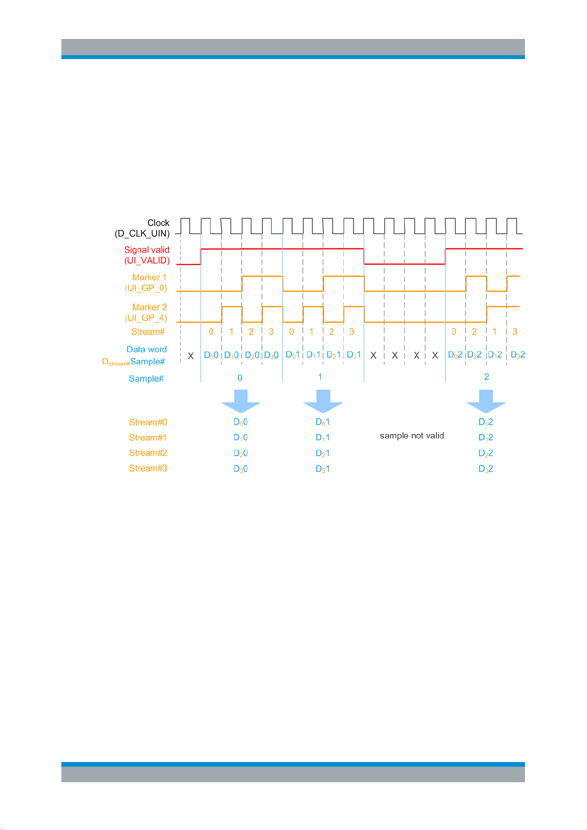
The multiplexing follows the rules:
●
Streams are numbered as stream#0 to stream#3 per digital I/Q output interface.
For example, stream A at the BBMM 1 OUT and stream B at the BBMM 2 OUT are
both indicated as stream#0
●
Samples belonging to a stream are indicated by a combination of two marker signals UI_GP_0 and UI_GP_4;
(on Figure 3-2 data samples are indicated as D
●
Samples order can vary, see the third sample on Figure 3-2
●
Signal valid (UI_VALID) indicates valid samples, see Figure 3-3
●
Clock signal D_CLK_UIN is required as a reference for PLL
●
Digital I/Q data is output as I and Q signals UI_I_0 ... UI_I_17 and UI_Q_0 ...
stream#
Sample#)
UI_Q_17.
●
Evaluate multiplexed samples one by one (see also Figure 3-3)
14User Manual 1176.9564.02 ─ 12
Page 15
R&S®SMW-K551
About the Slow IQ Signal Generation
Transmission Modes
Example: Signal at the user interface of the R&S EX-IQ-Box (four multiplexed
streams)
In the following, we assume:
●
An 1xMx8 system configuration, where the four streams B, D, F and H are multiplexed for the BBMM 2 OUT digital interface
●
A 16-bit data word and a parallel data format
The Figure 3-2 shows the multiplexed signal at the user interface of the R&S EX-IQBox.
Figure 3-2: Example: Signal at the user interface of the R&S EX-IQ-Box (four multiplexed streams)
Stream#0 = Stream B
Stream#1 = Stream D
Stream#2 = Stream F
Stream#3 = Stream H
Example: Signal at the user interface of the R&S EX-IQ-Box (one multiplexed
stream)
In the following, we assume:
●
An 1xMx3 system configuration, where the stream B is multiplexed for the BBMM 2
OUT digital interface
●
There is no second stream multiplexed on this digital interface
●
The samples of stream B are indicated as Stream#0; all other samples are unused
and are discarded
The Figure 3-3 shows the multiplexed signal at the user interface of the R&S EX-IQBox.
15User Manual 1176.9564.02 ─ 12
Page 16

R&S®SMW-K551
About the Slow IQ Signal Generation
Default Stream Mapping
Figure 3-3: Example: Signal at the user interface of the R&S EX-IQ-Box (one multiplexed stream)
X = unused samples (to be discarded)
Stream#0 = Stream B
3.4 Default Stream Mapping
The Table 3-2 and Table 3-3 provide information on the following:
●
Default stream mapping to the digital interfaces
●
Default interface direction
●
Possible configurations depending on the selected system configuration and the
transmission mode (single or multiplexed streams).
See Chapter 3.1, "Required Options and Equipment", on page 11 for an overview
of the required options for each transmission type.
The following abbreviations are used:
●
* depicts two or more multiplexed streams
●
M depicts the number of generated basebands; value range 1 to 8
Table 3-2: Single stream ("Signal Outputs > Digital Only"): Possible scenarios and default stream
System Configuration BBMM 1 OUT BBMM 2 OUT FADER 3 OUT FADER 4 OUT
1xMx2 Stream A Stream B - -
1xMx3 Stream A Stream B Stream C -
1xMx4
2xMx2
mapping
Stream A Stream B Stream C Stream D
16User Manual 1176.9564.02 ─ 12
Page 17

R&S®SMW-K551
About the Slow IQ Signal Generation
Default Stream Mapping
Table 3-3: Multiplexed streams ("Signal Outputs > Digital Only Multiplexed"): Possible scenarios and
System Configuration BBMM 1 OUT BBMM 2 OUT
1xMx2 n.a n.a
1xMx3 Stream A*C Stream B
1xMx4
2xMx2
1xMx8
3xMx2
4xMx2
5x1x1
default stream mapping
Stream A*C Stream B*D
Stream A*C*E*G Stream B*D*F*H
3.4.1 Limitations and Interdependencies with Other Parameters
When you generate digital signals (I/Q streams) as "slow IQ" signals, consider that the
following applies:
●
The R&S SMW synchronizes the generated baseband to its internal clock signal;
external clock signals are not supported.
●
The clock rate required by the R&S EX-IQ-Box has to be smaller than the sampling
rate of the generated digital signal:
ClockRate
R&S EX-IQ-Box
(see also Example "How to find out the max ClockRate
tional reference frequency is not required" on page 18.)
●
If multiplexed streams are used, the generated baseband signals have limited maximum baseband bandwidths BW, which also influences
ence the baseband bandwidth-related parameters. The latter applies, for example,
for the maximum frequency offset, ARB sample rate, or AWGN.
See Table 3-4.
Note: The maximum stream bandwidth must not exceed the provided maximum
baseband bandwidth: BW
Table 3-4: Multiplexed streams ("Signal Outputs > Digital Only Multiplexed"): Maximum baseband
bandwidth depending on the number of multiplexed streams
≤ SamplingRate
≤ BW
Stream
*#MuxStreams
Stream
Baseband_max
R&S EX-IQ-Box
Baseband_max
for that an addi-
, which also influ-
#MuxStreams Baseband bandwidth-related
parameters, e.g. frequency offset
1, 2 +/- 200 MHz 80 MHz
3, 4 +/- 100 MHz 80 MHz
> 4 +/- 50 MHz 40 MHz
To utilize the full available stream bandwidth BW
Stream
BW
Baseband_max
, use the single stream transmis-
sion.
Consider that one R&S EX-IQ-Box per streams is required.
17User Manual 1176.9564.02 ─ 12
Page 18

R&S®SMW-K551
3.5 Synchronization Issues
About the Slow IQ Signal Generation
Synchronization Issues
In test setups with more than one instrument, it is essential that all instruments use the
same reference clock.
While testing DUTs with "slow IQ" signals, the clock signal is usually provided by the
DUT. Even in a test setup with several R&S EX-IQ-Box, you only have to distribute the
clock signal of the DUT to the R&S EX-IQ-Box and to set the clock rate. Additional reference frequency is not required. See also Figure 5-1.
If you, however, generate signals with clock rate that is equal to the sampling rate of
the digital standard, you have to provide all instruments with the same reference frequency. (See Figure 3-4).
Figure 3-4: Simplified test setup for MIMO tests with external reference signal
* = not all required connections are shown
Example: How to find out the max ClockRate
R&S EX-IQ-Box
for that an additional ref-
erence frequency is not required
The clock rate of the R&S EX-IQ-Box is calculated by the formula:
ClockRate
●
R&S EX-IQ-Box
Assume that the R&S SMW generates one digital stream with SamplingRate
Stream
< SamplingRate
= 100 MHz.
*#MuxStreams
Stream
If the DUT requires a signal with Clock Rate < 100 MHz, no additional reference
frequency is required.
●
If the R&S SMW generates two streams with SamplingRate
= 100 MHz each,
Stream
an additional reference frequency is required for Clock Rate = 200 MHz.
18User Manual 1176.9564.02 ─ 12
Page 19

R&S®SMW-K551
4 Slow IQ Related Settings
Slow IQ Related Settings
Generation of slow IQ signals is a feature that requires the additional option
R&S SMW-K551.
To access the "System Configuration" settings
1. In the taskbar R&S SMW, select the "System Configuration > System Configura-
tion".
The "Fading/Baseband Configuration" settings are displayed.
2. Select "Signal Outputs > Digital Only Multiplexed".
3. Configure, for example, an 1x2x8 MIMO scenario:
a) Select "Mode > Advanced"
b) Select "Entities = 1", "Basebands = 2" and "Streams = 8"
c) Select "BB Source Config > Coupled Sources"
4. Select "Apply".
With the selected configuration, the instrument generates digital signals only; the
analog outputs are disabled and the "External RF and IQ" tab is not displayed.
5. Select "I/Q Stream Mapper" to observe the mapping of the generated streams to
the digital I/Q interfaces.
The generated digital streams are mapped to the digital interfaces, as described in
Default Stream Mapping; if multiplexed streams are used, the mapping is fixed.
19User Manual 1176.9564.02 ─ 12
Page 20

R&S®SMW-K551
Slow IQ Related Settings
The block diagram confirms the generation of digital only signals, too.
1
1
1
= Separated routing for RF analog outputs and disabled I/Q outputs
2 = Indication of multiplexed streams, e.g. streams A*C*E*G are routed to the BBMM 1 connector (see
Table 3-3)
To access the "I/Q Digital" settings
1. In the block diagram, select "I/Q Digital".
2
20User Manual 1176.9564.02 ─ 12
Page 21

R&S®SMW-K551
Slow IQ Related Settings
Note:
Multiplexed digital streams that are routed to the same digital output interface
BBMM 1 or BBMM 2 have the same signal parameters:
● sampling rate, i.e. the available bandwidth is distributed evenly
● impairments
● parameters describing the digital output signal, i.e. peak level and level values.
2. To configure the level settings of the output streams, select "Signal Output".
For step-by-step description on how to use the provided settings, refer to Chapter 5,
"How To Generate Signals with Reduced Speed for FPGA Tests", on page 24.
System Configuration> Fading/Baseband Configuration
Available are the standard settings and the following parameter, dedicated to the "slow
IQ" signal generation.
21User Manual 1176.9564.02 ─ 12
Page 22

R&S®SMW-K551
Slow IQ Related Settings
Signal Outputs ← System Configuration> Fading/Baseband Configuration
Defines whether an analog and digital or digital only signal is generated.
The keyword (HS) indicates that the signal is routed to the HS DIG I/Q connectors. If
this keyword is missing, the signal is routed to the DIG I/Q connectors.
Baseband generator
R&S SMW-B10 Standard
R&S SMW-B9 Standard "Analog Only" Disables the digital outputs.
Mode Signal Out-
puts
"Analog&Digi-
Advanced
Advanced "Digital Only" Baseband signal can only be output as digital signal at the
Advanced "Digital Only
Advanced "Analog&Digi-
tal"
Multiplexed"
"Digital Only
(HS)"
tal"
Description Options
The instrument generates signals with high data rate.
Generated streams can be mapped to the analog connectors
and to the DIG I/Q interfaces.
DIG I/Q interfaces. The baseband signal cannot be routed to
the RF and I/Q analog output.
Analog signal generation is possible with external analog I/Q
signals. Alternatively, you can generate continuous wave signals, analog modulated signals or RF signals in sweep or list
mode.
R&S SMW can process up to 4 multiplexed streams received
over the same connector.
With options R&S SMW-B10 and R&S SMW-K551, the
R&S SMW can also generate digital signals with reduced
speed, depending on the device connected to the digital I/Q
interfaces. The multiplexed streams are then mapped to the
digital I/Q interfaces BBMM 1/2; the mapping is fixed.
Works like "Digital Only" in Standard baseband but the baseband signal is output at the HS DIG I/Q interface.
Generated streams can be mapped to the analog connectors
and to the DIG I/Q interfaces.
R&S SMWK18
R&S SMWK18
R&S SMWK19
"Digital Only
(HS)"
Works like "Digital Only" in Standard baseband but the baseband signal is output at the HS DIG I/Q interface.
R&S SMWK19
See user manual R&S SMW-K551 Generation of Digital "Slow IQ" Signals.
Remote command:
:SCONfiguration:OUTPut:MODE on page 30
I/Q Digital Outputs
Available are the standard settings and the following parameters, dedicated to the
"slow IQ" signal generation.
Slow IQ State ← I/Q Digital Outputs
Option: R&S SMW-K551
If "Digital Only" or "Digital Only Multiplexed" signals are generated, this parameter
shows whether a "Sample Clock Request" is enabled in the connected R&S EX-IQBox.
All digital outputs must work in the same mode, that is with "Slow IQ = On" or "Slow IQ
= Off". You can change the state of any one of the outputs; the state of the other is set
automatically.
22User Manual 1176.9564.02 ─ 12
Page 23

R&S®SMW-K551
Slow IQ Related Settings
Remote command:
[:SOURce]:IQ:OUTPut:DIGital:BBMM<ch>:SLOW:STATe on page 30
Level Channel# (Stream) ← I/Q Digital Outputs
Displays the resulting signal level of each multiplexed stream.
23User Manual 1176.9564.02 ─ 12
Page 24

R&S®SMW-K551
5 How To Generate Signals with Reduced
How To Generate Signals with Reduced Speed for FPGA Tests
Speed for FPGA Tests
The following is a list of some important settings. Not all required settings are considered.
For detailed information on the required steps, refer to the documents listed in Chap-
ter 7, "Further Information", on page 31.
How To Generate a 1x2x4 MIMO Digital Signal for FPGA Tests with Slow IQ Signals
The test setup and the configuration required to generate signals with reduced speed
undergoes a group of main steps. The explanation of the configuration principle is
based on one particular use case.
1. Connecting the instruments.
See "To connect the instruments for "slow IQ" tests" on page 24
2. Configuring the R&S SMW to generate the required signal.
See "To configure the R&S SMW" on page 24
3. Configuring the DUT (if required) and determining its clock rate.
4. Configuring the digital interface module R&S EX-IQ-Box.
See "To configure the R&S EX-IQ-Box" on page 25
To connect the instruments for "slow IQ" tests
Use the example test setup on Figure 3-1 but use four R&S EX-IQ-Box instead.
The test setup assumes a ClockRate
1. Connect the four interface modules R&S EX-IQ-Box to the R&S SMW.
Connect the DUT to the four interface modules R&S EX-IQ-Box.
2. Provide all four interface modules R&S EX-IQ-Box with the clock signal of the DUT
to ensure a synchronous signal generation.
To configure the R&S SMW
1. Select "System Configuration" and:
a) enable a 1x2x4 MIMO scenario
b) enable "BB Sources > Coupled"
c) select "Signal Outputs > Digital Only".
R&S EX-IQ-Box
< SamplingRate
Stream
.
2. Enable the generation of a baseband signal, e.g. :
a) select "Baseband > EUTRA/LTE" and enable a signal with "Channel Bandwidth
= 20 MHz", e.g. select "General > Test Models > E-TM1_1__20MHz"
24User Manual 1176.9564.02 ─ 12
Page 25

R&S®SMW-K551
How To Generate Signals with Reduced Speed for FPGA Tests
b) Select "EUTRA/LTE > General > Filter/Clipping ... > Filter".
The parameter "Sample Rate Variation = 30.72 MHz" indicates the user sample
rate.
c) Select "EUTRA/LTE > State > On".
3. Select "I/Q Digital Outputs > General" and for each of the streams configure:
a) "Source > User Defined"
b) "Value = 30.72 MHz"
Each generated stream will be generate with this sample rate.
4. Select "I/Q Digital Outputs > State > On"
To configure the R&S EX-IQ-Box
We assume that an external PC is connected to the R&S EX-IQ-Box, the R&S
DigIConf software is running on this external PC and the R&S EX-IQ-Box is controlled
form the software.
Several settings of the R&S EX-IQ-Box have to be configured are required by the connected DUT.
1. Start the R&S DigIConf software.
2. Select "DIG-IQ-IN > SMW > Hardware Info > Slow I/Q Sample Clock Request >
On".
25User Manual 1176.9564.02 ─ 12
Page 26

R&S®SMW-K551
How To Generate Signals with Reduced Speed for FPGA Tests
In the R&S SMW, the parameter "I/Q Digital Outputs > General > Slow IQ > State >
On" confirms that the R&S EX-IQ-Box requests the sample clock automatically.
3. Select "EX-IQ-Box: User Defined > Direction > Transmitter".
4. Select "EX-IQ-Box: User Defined > Protocol" and "EX-IQ-Box: User Defined >
Data" and change the default settings, if required.
5. Select "EX-IQ-Box: User Defined > Clock" and configure:
● "Clock Source > User Interface"
● set the value of the parameter "Clock Rate" to the clock required by the DUT,
i.e. ClockRate
EX-IQ-Box
E.g. if the DUT requires a 1 MHz clock signal, ClockRate
= Clock
DUT
.
EX-IQ-Box
= 1 MHz
26User Manual 1176.9564.02 ─ 12
Page 27

R&S®SMW-K551
How To Generate Signals with Reduced Speed for FPGA Tests
6. Select "EX-IQ-Box: User Defined > State > On".
7. In the R&S DigIConf, select the smart graphic "TR1" to enlarge it.
The "Transient Recorder" dialog opens and confirms the expected LTE spectrum.
How To Generate a 1x2x8 MIMO Digital Signal for FPGA Tests with Slow IQ Signals
Follow the main steps described in "How To Generate a 1x2x4 MIMO Digital Signal for
FPGA Tests with Slow IQ Signals" on page 24:
1. Connecting the instruments as shown on Figure 5-1.
27User Manual 1176.9564.02 ─ 12
Page 28

R&S®SMW-K551
How To Generate Signals with Reduced Speed for FPGA Tests
Figure 5-1: Simplified test setup for 2x8 MIMO tests with "slow IQ" signals
Clock = the clock signal of the DUT must be provided to both R&S EX-IQ-Box
2. Configure the R&S SMW to generate the required signal.
For example, an LTE signal in a 1x2x8 MIMO configuration and enable "Signal
Outputs > Digital Only Multiplexed".
3. If Fading simulation is required:
a) select "Fading > General > Virtual RF = 2.14 GHz"
b) select "Fading > Standard > LTE-MIMO > ETU 70Hz Medium"
c) select "Fading > State > On"
4. Configure the DUT (if required) and sets its clock rate.
28User Manual 1176.9564.02 ─ 12
Page 29

R&S®SMW-K551
How To Generate Signals with Reduced Speed for FPGA Tests
5. Configure the digital interface module R&S EX-IQ-Box as described in "To config-
ure the R&S EX-IQ-Box" on page 25.
The generated signal is processed in a way, that each of the four multiplexed
stream will have a sampling rate of 250 KHz.
29User Manual 1176.9564.02 ─ 12
Page 30

R&S®SMW-K551
6 Remote Control Commands
Remote Control Commands
:SCONfiguration:OUTPut:MODE <Mode>
Defines what kind of signal is generated and which output interfaces are enabled.
Parameters:
<Mode> DIGMux | DIGital | ALL | ANALog | HSDigital | HSALl
ALL
Output at the analog (RF and I/Q) and the digital DIG I/Q interfaces.
DIGital | DIGMux
Signal is output as single stream or multiplexed digital signal at
the DIG I/Q interfaces.
ANALog
Output at the analog (RF and I/Q) interfaces.
HSDigital
Output at the interfaces HS DIG I/Q interfaces.
HSALl
Output at the analog (RF and I/Q) and the digital HS DIG I/Q
interfaces.
*RST:
ALL
Example:
Options: DIGMux requires R&S SMW-K551
Manual operation: See "Signal Outputs" on page 22
[:SOURce]:IQ:OUTPut:DIGital:BBMM<ch>:SLOW:STATe <SlowIqState>
Enables/disables slow IQ mode.
See user manual R&S SMW-K551 Generation of Digital "Slow IQ" Signals.
Parameters:
<SlowIqState> 0 | 1 | OFF | ON
Options: R&S SMW-K551
Manual operation: See "Slow IQ State" on page 22
SCONfiguration:OUTPut:MODE ALL
DIGital requires R&S SMW-K18/-K19
ANALog|HSDigital|HSALl require R&S SMW-B9 and R&S SMWK19
*RST: 0
30User Manual 1176.9564.02 ─ 12
Page 31

R&S®SMW-K551
7 Further Information
Further Information
For a comprehensive description of the R&S SMW, R&S EX-IQ-Box and R&S DigIConf
software, refer to:
●
the R&S SMW user manual
●
the R&S EX-IQ-Box - Digital Interface Module & DigIConf Configuration Software
Operating Manual
●
the EUTRA/LTE Digital Standard for R&S SMW user manual
The latest versions are available for download at the product homepage
●
http://www.rohde-schwarz.com/product/SMW200A.html
●
http://www.rohde-schwarz.com/product/EX-IQ-Box.html
31User Manual 1176.9564.02 ─ 12
Page 32

R&S®SMW-K551
List of Commands
List of Commands
:SCONfiguration:OUTPut:MODE.....................................................................................................................30
[:SOURce]:IQ:OUTPut:DIGital:BBMM<ch>:SLOW:STATe.............................................................................. 30
32User Manual 1176.9564.02 ─ 12
Page 33

R&S®SMW-K551
Index
Index
A
Application cards ................................................................. 7
Application notes ................................................................. 7
B
Brochures ............................................................................ 7
D
Data sheets ......................................................................... 7
Digital only signals
Settings ....................................................................... 22
Documentation overview ..................................................... 5
G
Getting started ..................................................................... 6
H
Help ..................................................................................... 6
I
Installation ........................................................................... 9
Instrument help ................................................................... 6
Instrument security procedures ........................................... 6
M
U
User manual ........................................................................ 6
W
White papers ....................................................................... 7
Multiplexed digital streams
Settings ....................................................................... 22
O
Open source acknowledgment (OSA) ................................. 7
Output signal
Digital only .................................................................. 22
R
Reduced speed signal
a.k.a. Slow IQ ............................................................... 9
Release notes ..................................................................... 7
S
Safety instructions ............................................................... 7
Service manual ................................................................... 6
Signal outputs
Fading and baseband configuration ........................... 22
Slow IQ
Definition ....................................................................... 9
see "reduced speed" ..................................................... 9
Slow IQ signals
Settings ....................................................................... 22
T
Tutorials ............................................................................... 6
33User Manual 1176.9564.02 ─ 12
 Loading...