

Page 1

R&S®SMW-K111
GBAS
User Manual
(;Üîè2)
1178969002
User Manual
Version 03
Page 2

This document describes the following software option:
●
R&S®SMW-K111
1414.3059.02
This manual describes firmware version FW 4.70.026.xx and later of the R&S®SMW200A.
© 2019 Rohde & Schwarz GmbH & Co. KG
Mühldorfstr. 15, 81671 München, Germany
Phone: +49 89 41 29 - 0
Fax: +49 89 41 29 12 164
Email: info@rohde-schwarz.com
Internet: www.rohde-schwarz.com
Subject to change – Data without tolerance limits is not binding.
R&S® is a registered trademark of Rohde & Schwarz GmbH & Co. KG.
Trade names are trademarks of their owners.
1178.9690.02 | Version 03 | R&S®SMW-K111
Throughout this manual, products from Rohde & Schwarz are indicated without the ® symbol, e.g. R&S®SMW is indicated as
R&S SMW.
Page 3

R&S®SMW-K111
1 Preface.................................................................................................... 5
1.1 About this Manual......................................................................................................... 5
1.2 Documentation Overview............................................................................................. 6
2 Welcome to the GBAS Option...............................................................8
2.1 Accessing the GBAS Dialog........................................................................................ 9
2.2 Scope............................................................................................................................. 9
3 About the GBAS Option...................................................................... 10
3.1 Required Options........................................................................................................ 10
3.2 About GBAS................................................................................................................ 10
4 GBAS Configuration and Settings......................................................17
Contents
Contents
4.1 General Settings..........................................................................................................17
4.2 Transmitter Settings................................................................................................... 20
4.3 Message Configuration Settings............................................................................... 22
4.4 Allocation and Frequency/Scheduling Settings.......................................................44
5 Signal Generation Control...................................................................50
5.1 Filter/Clipping Settings...............................................................................................50
5.2 Trigger Settings...........................................................................................................54
5.3 Marker Settings........................................................................................................... 59
5.4 Clock Settings............................................................................................................. 60
5.5 Local and Global Connector Settings....................................................................... 61
6 How to Work with the GBAS Option...................................................62
6.1 Loading Differential GBAS Data................................................................................ 62
7 Remote-Control Commands............................................................... 63
7.1 Programming Examples............................................................................................. 63
7.2 General Commands.................................................................................................... 69
7.3 Transmitter Commands..............................................................................................72
7.4 Scheduling Commands.............................................................................................. 75
7.5 Message Configuration Commands..........................................................................78
7.6 Filter, Clipping, Modulation Commands..................................................................105
3User Manual 1178.9690.02 ─ 03
Page 4

R&S®SMW-K111
7.7 Trigger Commands................................................................................................... 108
7.8 Marker Commands.................................................................................................... 112
7.9 Clock Commands...................................................................................................... 114
A Supported File Formats.....................................................................115
A.1 Waypoint File Format................................................................................................115
A.2 GBAS Differential File Format..................................................................................115
A.3 SCAT-I Differential File Format.................................................................................117
Contents
Annex.................................................................................................. 115
Glossary: Specifications and References........................................119
List of Commands..............................................................................120
Index....................................................................................................124
4User Manual 1178.9690.02 ─ 03
Page 5

R&S®SMW-K111
1 Preface
1.1 About this Manual
Preface
About this Manual
This user manual provides all the information specific to the GBAS option
R&S SMW-K111. All general instrument functions and settings common to all applications and operating modes are described in the main R&S SMW user manual.
The main focus in this manual is on the provided settings and the tasks required to
generate a signal. The following topics are included:
●
Welcome to the GBAS option R&S SMW-K111
Introduction to and getting familiar with the option
●
About the GBAS
Background information on basic terms and principles in the context of the signal
generation
●
GBAS Configuration and Settings
A concise description of all functions and settings available to configure signal generation with their corresponding remote control command
●
Remote Control Commands
Remote commands required to configure and perform signal generation in a
remote environment, sorted by tasks
(Commands required to set up the instrument or to perform common tasks on the
instrument are provided in the main R&S SMW user manual)
Programming examples demonstrate the use of many commands and can usually
be executed directly for test purposes
●
Annex
Reference material
●
List of remote commands
Alphabetical list of all remote commands described in the manual
●
Index
Contents and scope
This description assumes R&S SMW equipped with all availabe options. Depending on
your model and the installed options, some of the functions may not be available on
your instrument.
Notes on screenshots
When describing the functions of the product, we use sample screenshots. These
screenshots are meant to illustrate as much as possible of the provided functions and
possible interdependencies between parameters. The shown values may not represent
realistic usage scenarios.
5User Manual 1178.9690.02 ─ 03
Page 6

R&S®SMW-K111
1.2 Documentation Overview
1.2.1 Getting Started Manual
Preface
Documentation Overview
The screenshots usually show a fully equipped product, that is: with all options installed. Thus, some functions shown in the screenshots may not be available in your particular product configuration.
This section provides an overview of the R&S SMW user documentation. Unless specified otherwise, you find the documents on the R&S SMW product page at:
www.rohde-schwarz.com/manual/smw200a
Introduces the R&S SMW and describes how to set up and start working with the product. Includes basic operations, typical measurement examples, and general information, e.g. safety instructions, etc. A printed version is delivered with the instrument.
1.2.2 User Manuals and Help
Separate manuals for the base unit and the software options are provided for download:
●
Base unit manual
Contains the description of all instrument modes and functions. It also provides an
introduction to remote control, a complete description of the remote control commands with programming examples, and information on maintenance, instrument
interfaces and error messages. Includes the contents of the getting started manual.
●
Software option manual
Contains the description of the specific functions of an option. Basic information on
operating the R&S SMW is not included.
The contents of the user manuals are available as help in the R&S SMW. The help
offers quick, context-sensitive access to the complete information for the base unit and
the software options.
All user manuals are also available for download or for immediate display on the Internet.
1.2.3 Tutorials
The R&S SMW provides interactive examples and demonstrations on operating the
instrument in form of tutorials. A set of tutorials is available directly on the instrument.
6User Manual 1178.9690.02 ─ 03
Page 7

R&S®SMW-K111
1.2.4 Service Manual
1.2.5 Instrument Security Procedures
1.2.6 Basic Safety Instructions
Preface
Documentation Overview
Describes the performance test for checking the rated specifications, module replacement and repair, firmware update, troubleshooting and fault elimination, and contains
mechanical drawings and spare part lists.
The service manual is available for registered users on the global Rohde & Schwarz
information system (GLORIS, https://gloris.rohde-schwarz.com).
Deals with security issues when working with the R&S SMW in secure areas. It is available for download on the Internet.
Contains safety instructions, operating conditions and further important information.
The printed document is delivered with the instrument.
1.2.7 Data Sheets and Brochures
The data sheet contains the technical specifications of the R&S SMW. It also lists the
options and their order numbers and optional accessories.
The brochure provides an overview of the instrument and deals with the specific characteristics.
See www.rohde-schwarz.com/brochure-datasheet/smw200a
1.2.8 Release Notes and Open Source Acknowledgment (OSA)
The release notes list new features, improvements and known issues of the current
firmware version, and describe the firmware installation.
The open source acknowledgment document provides verbatim license texts of the
used open source software.
See www.rohde-schwarz.com/firmware/smw200a
1.2.9 Application Notes, Application Cards, White Papers, etc.
These documents deal with special applications or background information on particular topics.
See www.rohde-schwarz.com/application/smw200a and www.rohde-schwarz.com/
manual/smw200a
7User Manual 1178.9690.02 ─ 03
Page 8

R&S®SMW-K111
2 Welcome to the GBAS Option
Welcome to the GBAS Option
The R&S SMW-K111 is a firmware application that adds functionality to generate signals in accordance with the Ground-Based Augmentation System (GBAS) standard.
The R&S SMW-K111 features
●
Generation of the VHF Data Broadcast (VDB) Signal-in-Space signal transmitted
from the GBAS ground subsystem to the airborne subsystem
●
User-definable transmission band and support of single and multi-frequency transmission (up to 11 frequency channels simultaneously), for example for adjacent
channel emissions measurements
●
Support of GBAS mode:
– Configuration of local area augmentation system (LAAS) message blocks
– Configuration of GBAS application data, for example the parameters of mes-
sage type 2 and 4, incl. the Final Approach Segment (FAS) data definition and
Terminal Area Path (TAP) data
– Import of differential global navigation satellite system (DGNSS) data (message
type 1 and 11)
– Encoding, timing and power settings according to the specification RTCA
DO-246D.
●
Support of SCAT-I mode:
– Configuration of special category (SCAT-I) message blocks
– Configuration of GBAS application data, for example the parameters of mes-
sage type 4, incl. the Final Approach Segment (FAS) data definition data
– Import of differential global navigation satellite system (DGNSS) data (message
type 1 and 11)
– Encoding, timing and power settings according to the specification RTCA
DO-217H.
This user manual contains a description of the functionality that the application provides, including remote control operation.
All functions not discussed in this manual are the same as in the base unit and are
described in the R&S SMW user manual. The latest version is available at:
www.rohde-schwarz.com/manual/SMW200A
Installation
You can find detailed installation instructions in the delivery of the option or in the
R&S SMW service manual.
8User Manual 1178.9690.02 ─ 03
Page 9
R&S®SMW-K111
2.1 Accessing the GBAS Dialog
2.2 Scope
Welcome to the GBAS Option
Scope
To open the dialog with GBAS settings
► In the block diagram of the R&S SMW, select "Baseband > GBAS".
A dialog box opens that displays the provided general settings.
The signal generation is not started immediately. To start signal generation with the
default settings, select "State > On".
Tasks (in manual or remote operation) that are also performed in the base unit in the
same way are not described here.
In particular, it includes:
●
Managing settings and data lists, like storing and loading settings, creating and
accessing data lists, or accessing files in a particular directory.
●
Information on regular trigger, marker and clock signals and filter settings, if appropriate.
●
General instrument configuration, such as checking the system configuration, configuring networks and remote operation
●
Using the common status registers
For a description of such tasks, see the R&S SMW user manual.
9User Manual 1178.9690.02 ─ 03
Page 10

R&S®SMW-K111
3 About the GBAS Option
3.1 Required Options
3.2 About GBAS
About the GBAS Option
About GBAS
The equipment layout for generating GBAS signals includes:
●
Option Standard Baseband Generator (R&S SMW-B10) per signal path
●
Option Baseband main module, one/two I/Q paths to RF (R&S SMW-B13/-B13T)
●
Option GBAS (R&S SMW-K111) per signal path
●
Frequency option (e.g. R&S SMW-B1003)
The R&S SMW-K111 option enables you to define and configure the very high frequency (VHF) Data Broadcast (VDB) Signal-in-Space signal. VDB signals are transmitted from the Ground-Based Augmentation System (GBAS) ground subsystem to the
airborne subsystem. This implementation is in line with the specification RTCA
DO-246D. The instrument generates the GBAS signal at the physical layer and
includes configuration of the application data.
The GBAS is a ground-based augmentation system that could among other things
enhance satellite navigation to provide a position estimation of less than 1 meter. The
GBAS is intended to improve aircraft safety and to enhance satellite navigation and the
full range of precision approach and landing procedures, as well as the terminal area
operations. GBAS could replace the Instrument Landing System (ILS) and the Microwave Landing System (MLS) in many applications.
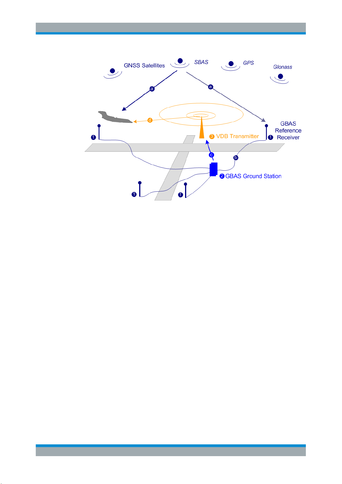
GBAS components
The illustration in Figure 3-1 is a simplified representation of the GBAS three main
components:
●
The GNSS satellite subsystem
●
The airborne subsystem
●
The GBAS ground subsystem
The ground equipment consists of four reference GNSS receivers at exactly defined
positions around the airport, GBAS ground station, and a VHF data broadcast transmitter (VDB).
10User Manual 1178.9690.02 ─ 03
Page 11
R&S®SMW-K111
About the GBAS Option
About GBAS
Figure 3-1: GBAS components and signals (simplified representation)
1 = GNSS reference receiver
2 = GBAS ground station
3 = VHF data broadcast (VDB) transmitter
a = GNSS navigation message
b = Pseudorange
c = GBAS Correction message
d = VDB signal
The GBAS GNSS reference receiver receives the GNSS navigation message, performs pseudorange measurements and transmits this information to the GBAS ground
station. The GBAS ground station determines errors in the calculated positions, adds
additional parameters and approach path information, produces a GBAS correction
message and sends it the VDB transmitter. The VDB transmitter modulates and encodes this message and broadcasts it to the airborne GBAS equipment, for example a
GBAS receiver in the airplane. The GBAS equipment in the airplane is a high-precision
multimode receiver that evaluates the message and applies corrections parameters to
improve the navigation algorithms from GPS.
This list outlines the three signals transmitted between the components which are
referred as GBAS Signal-in-Space:
●
GNSS satellite to GBAS ground subsystem navigation signal
●
GNSS satellite to GBAS airborne subsystem navigation signal
●
GBAS ground subsystem to GBAS airborne subsystem VHF data broadcast
This firmware option enables you to generate the VHF data broadcast
Carrier frequencies and frequency channels
The VHF data broadcast is defined for carrier frequencies within the range of 108.025
MHz to 117.975 MHz and carrier spacing of 25.0 kHz.
11User Manual 1178.9690.02 ─ 03
Page 12
R&S®SMW-K111
About the GBAS Option
About GBAS
The R&S SMW supports the whole required frequency range; you can modulate the
VHF signal on any one of these carrier frequencies. Moreover, this firmware option
supports two frequency allocation modes, a single frequency and a multiple frequency
transmission.
When you chose the frequency allocation mode, consider the following:
●
Single frequency mode is suitable to simulate the signal of up to eight VDB transmitters modulated on the same carrier frequency.
The signal calculation is fast and optimized for time sensitive applications.
This mode is also the choice if the DUT or the analyzing equipment supports single
band decoding.
●
Multi-frequency mode is suitable to allocate the VDB transmitters to up to 8 out of
11 adjacent frequency channels.
The generated signal is optimized for reduced adjacent and co-channel interference to neighboring systems. The setting time, however, increase significantly
compared to the single frequency mode.
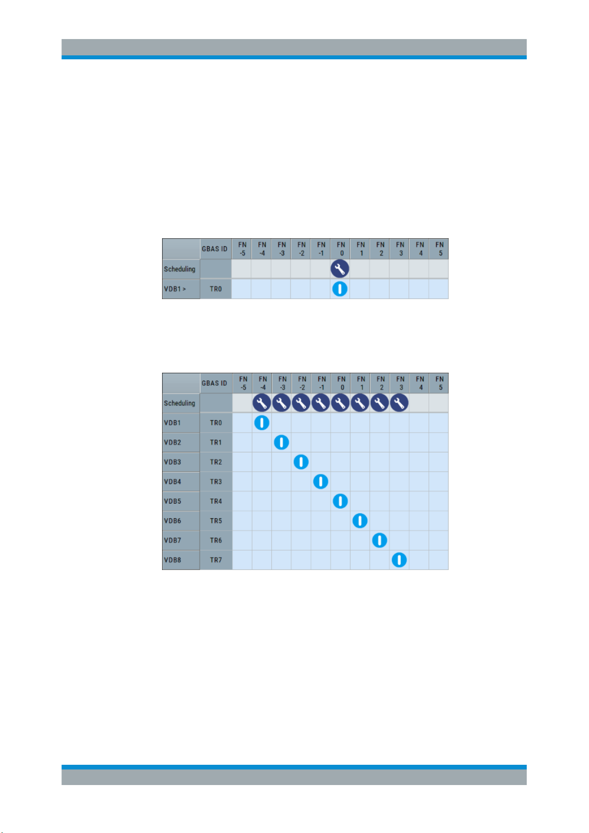
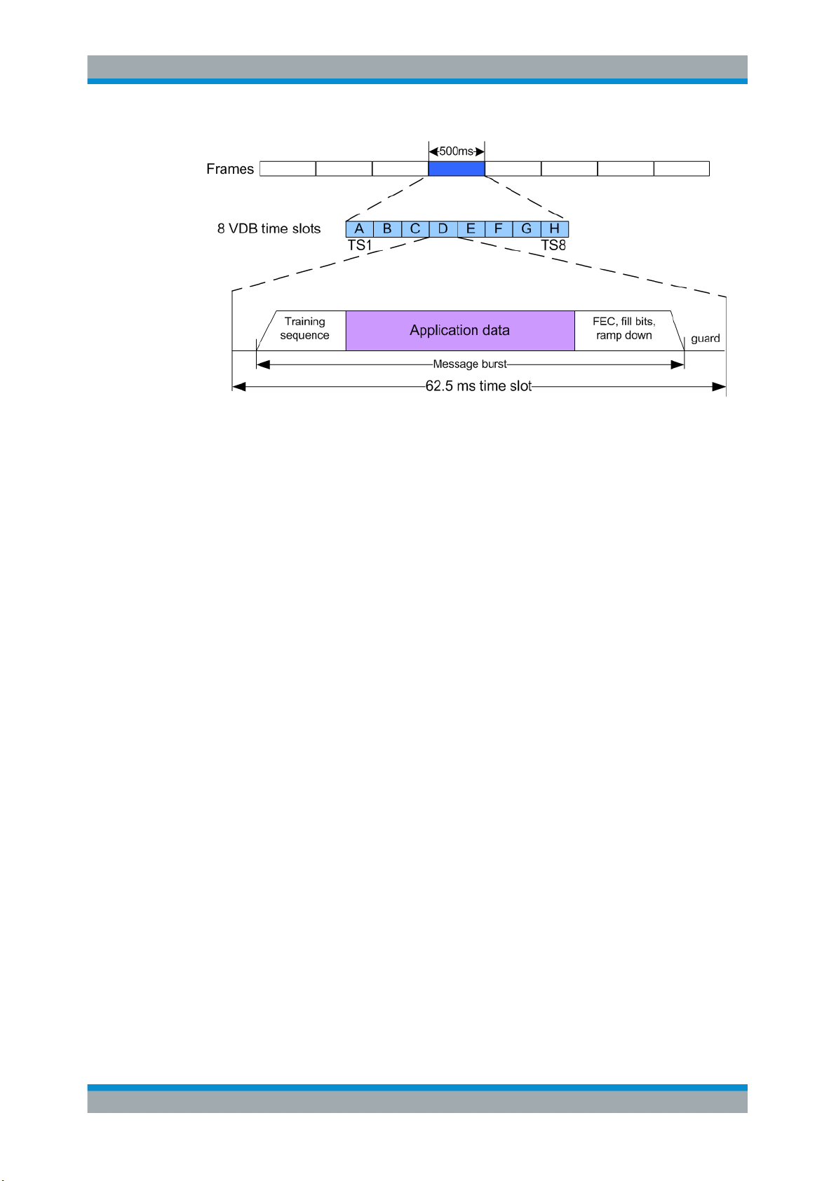
Broadcast timing structure
The broadcast is a Time Division Multiple Access (TDMA). According to the GBAS
specification RTCA DO-246D, the TDMA timing structure uses a two level hierarchy,
composed of 500 ms long frames, each divided into 8 VDB time slots (A - H), see Fig-
ure 3-2.
12User Manual 1178.9690.02 ─ 03
Page 13
R&S®SMW-K111
About the GBAS Option
About GBAS
Figure 3-2: TDMA timing structure (simplified representation)
A VDB time slot is the minimum resource that an individual VDB transmitter can use.
During one time slot, a VDB transmitter transmits exactly one burst.
The GBAS specification RTCA DO-246D defines the TDMA timing structure, including
timing budget of the VDB bursts, burst data contents and message encoding in great
details. The R&S SMW generates the required training sequence, encodes the message according to RTCA DO-246D and applies the D8PSK modulation automatically,
so that you can concentrate on the configuration of the mandatory application data.
Optional application data defined in RTCA DO-246D is beyond the scope of this implementation.
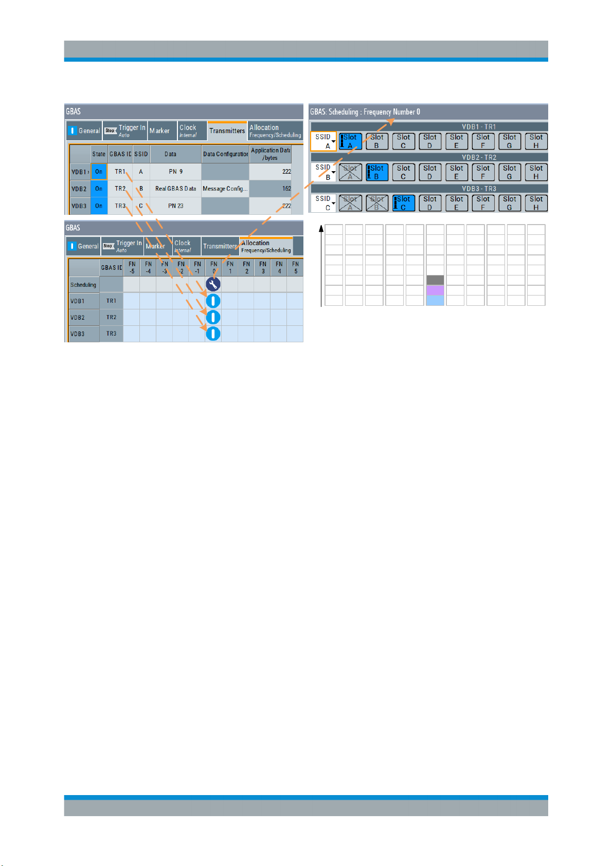
To allocate the VDB in the time domain, use the scheduling settings, see Chap-
ter 4.4.2, "Scheduling Settings", on page 45.
Refer to Figure 3-3 for illustration on how a multi-frequency TDMA scheduling is performed in this implementation.
13User Manual 1178.9690.02 ─ 03
Page 14
R&S®SMW-K111
About the GBAS Option
About GBAS
H
H
H
H
G
G
F
Time slots
E
D
C
B
A
FN -5 FN -4 FN -3 FN -2 FN -1 FN 0 FN 1 FN 2 FN 3 FN 4 FN 5
G
F
F
E
E
D
D
C
C
B
B
A
A
H
G
G
F
F
E
E
D
D
C
C
B
B
A
A
H
G
F
E
D
VDB3
VDB2
VDB1
H
G
F
E
D
C
B
A
H
H
G
G
F
E
D
C
B
A
G
F
E
D
C
B
A
H
H
G
F
F
E
E
D
D
C
C
B
B
A
A
Figure 3-3: Example of a multi-frequency TDMA scheduling
Power settings
In the R&S SMW, the following parameters have impact on the signal power of the time
slots:
●
RF output power ("Status Bar > Level")
Defines the RMS level of the generated signal
●
Relative power per time slot ("GBAS > Allocation > VDB# > Scheduling > Slot A
to H > Power")
Sets the relative power of a VDB per time slot (Slot A to H).
●
Power generation mode ("GBAS > Gated Power Mode")
Defines the way the absolute power of a VDB per time slot is calculated.
The absolute power of a single time slot depends on the power settings of the
remaining time slots.
See Example "Calculating the power per time slot in "Gated Power Mode > Off""
on page 15 and Example "Calculating the power per time slot in "Gated Power
Mode > On"" on page 15 for explanation on how the parameter "Gated Power
Mode" influence the calculation.
14User Manual 1178.9690.02 ─ 03
Page 15
R&S®SMW-K111
About the GBAS Option
About GBAS
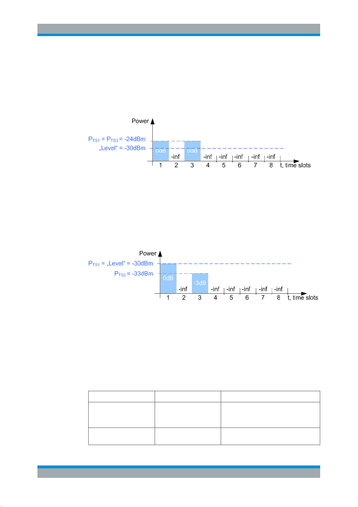
Example: Calculating the power per time slot in "Gated Power Mode > Off"
●
"Level = - 30 dBm"
●
"TS1 > State > On", relative power "TS1 > Pow(dB) = 0 dB"
●
"TS3 > State > On", relative power "TS3 > Pow(dB) = 0 dB"
●
"TS2/TS4/TS5/TS6/TS7/TS8 > State > Off"
"TS2/TS4/TS5/TS6/TS7/TS8 > Pow(dB) = -inf"
The absolute power of both scheduled time slots is P
TS1
= P
= -24 dBm.
TS3
Example: Calculating the power per time slot in "Gated Power Mode > On"
●
"Level = - 30 dBm"
●
"TS1 > State > On", relative power "TS1 > Pow(dB) = 0 dB"
●
"TS3 > State > On", relative power "TS3 > Pow(dB) = -3 dB"
●
"TS2/TS4/TS5/TS6/TS7/TS8 > State > Off"
"TS2/TS4/TS5/TS6/TS7/TS8 > Pow(dB) = -inf"
The absolute power of the scheduled time slots is:
●
P
= -30 dBm
TS1
●
P
= -33 dBm.
TS3
Supported message types
The GBAS specification RTCA DO-246D defines the following mandatory message
types. This implementation supports all required message types. Refer to Table 3-1 for
information on where to find the related settings.
Table 3-1: Overview of the required message types
Message type Description Related settings
1 Differential corrections
100 sec smoothed pseudoranges
2 GBAS-related data Chapter 4.3.2, "Message Type 2 Settings",
Chapter 4.3.1, "Message Type 1 & 11 Settings", on page 22
on page 24
15User Manual 1178.9690.02 ─ 03
Page 16
R&S®SMW-K111
About the GBAS Option
About GBAS
Message type Description Related settings
4 Final Approach Segment
(FAS) construction data
11 Differential corrections
Terminal Area Path (TAP)
construction data
30 sec smoothed pseudoranges
Chapter 4.3.3.2, "FAS Data Settings",
on page 34
Chapter 4.3.3.3, "TAP Data Settings",
on page 37
Chapter 4.3.1, "Message Type 1 & 11 Settings", on page 22
Rohde&Schwarz solution for radio analysis
If your task requires verifications and measurements of GBAS installations on the
ground and in the air, consider to use the R&S®EVS300 ILS/VOR analyzer.
This instrument is a portable level and modulation analyzer. If equipped with the
required options, it is capable to perform VHF data link measurements on GBAS and
measurements on conventional ILS ground systems and VOR systems.
16User Manual 1178.9690.02 ─ 03
Page 17
R&S®SMW-K111
4 GBAS Configuration and Settings
4.1 General Settings
GBAS Configuration and Settings
General Settings
Access:
► Select "Baseband > GBAS".
Settings:
● General Settings..................................................................................................... 17
● Transmitter Settings................................................................................................20
● Message Configuration Settings............................................................................. 22
● Allocation and Frequency/Scheduling Settings.......................................................44
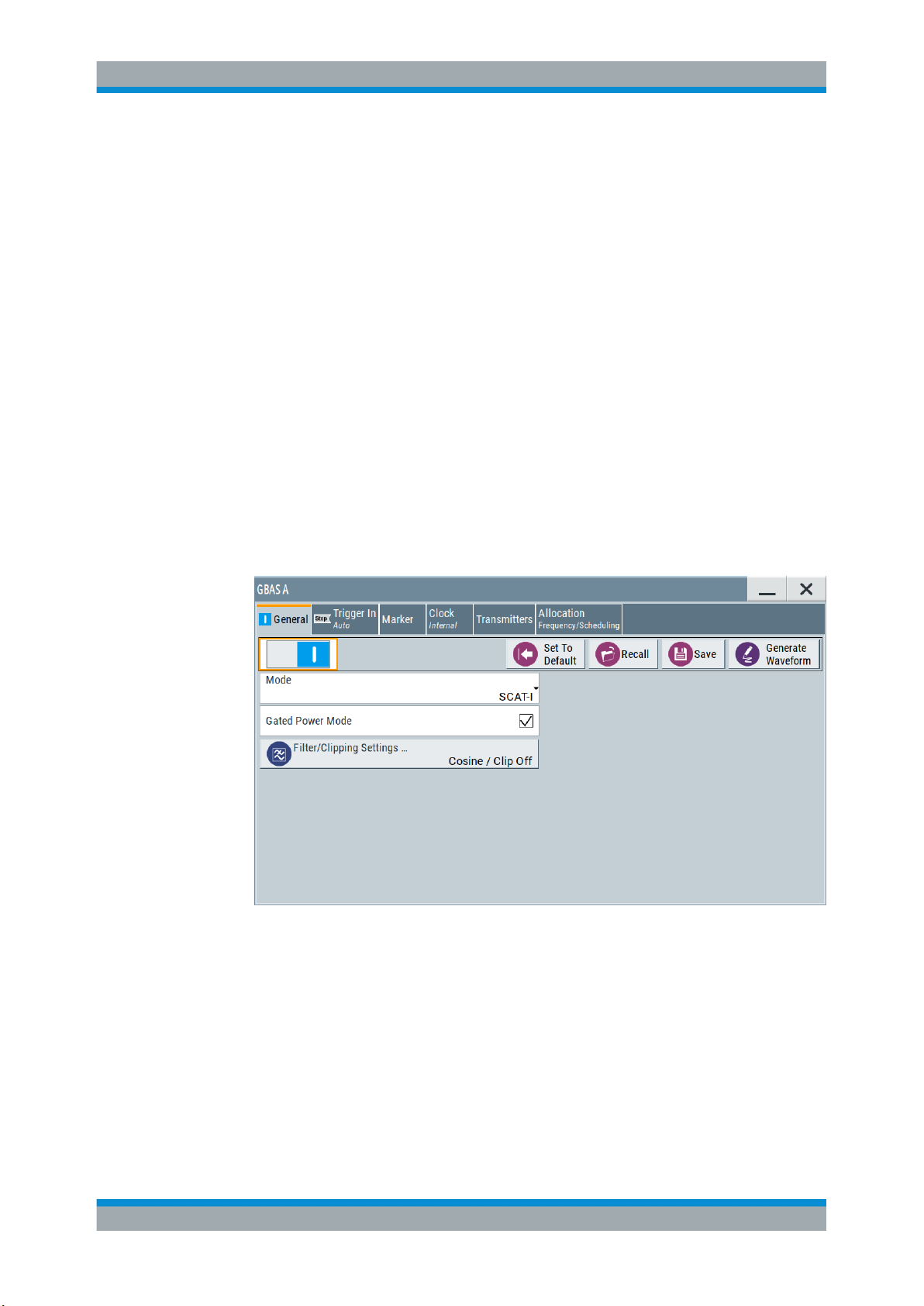
Access:
► Select "Baseband > GBAS > General".
This dialog provides access to the default and the "Save/Recall" settings, as well
as general GBAS settings and access to dialogs with further settings.
Settings:
State..............................................................................................................................18
Set to Default................................................................................................................ 18
Save/Recall...................................................................................................................18
Generate Waveform......................................................................................................19
17User Manual 1178.9690.02 ─ 03
Page 18
R&S®SMW-K111
GBAS Configuration and Settings
General Settings
Mode............................................................................................................................. 19
Gated Power Mode....................................................................................................... 19
Filter/Clipping Settings.................................................................................................. 19
State
Activates the GBAS standard.
Activation of the standard disables all the other digital standards and digital modulation
modes in the same baseband.
Remote command:
[:SOURce<hw>]:BB:GBAS:STATe on page 71
Set to Default
Calls the default settings. The values of the main parameters are listed in the following
table.
Parameter Value
State Not affected by the "Set to Default"
Mode GBAS
Gated Power Mode On
Sample Rate Variation 10.5 kHz
Filter Cosine
Clipping Off
Trigger Auto
Clock Internal
Remote command:
[:SOURce<hw>]:BB:GBAS:PRESet on page 69
Save/Recall
Accesses the "Save/Recall" dialog, that is the standard instrument function for saving
and recalling the complete dialog-related settings in a file. The provided navigation
possibilities in the dialog are self-explanatory.
The filename and the directory, in which the settings are stored, are user-definable; the
file extension is however predefined.
See also, chapter "File and Data Management" in the R&S SMW user manual.
Remote command:
[:SOURce<hw>]:BB:GBAS:SETTing:CATalog? on page 70
[:SOURce<hw>]:BB:GBAS:SETTing:DELete on page 70
[:SOURce<hw>]:BB:GBAS:SETTing:LOAD on page 70
[:SOURce<hw>]:BB:GBAS:SETTing:STORe on page 71
18User Manual 1178.9690.02 ─ 03
Page 19

R&S®SMW-K111
GBAS Configuration and Settings
General Settings
Generate Waveform
With enabled signal generation, triggers the instrument to store the current settings as
an ARB signal in a waveform file. Waveform files can be further processed by the ARB
and/or as a multi-carrier or a multi-segment signal.
The filename and the directory it is stored in are user-definable; the predefined file
extension for waveform files is *.wv.
Remote command:
[:SOURce<hw>]:BB:GBAS:WAVeform:CREate on page 71
Mode
Enables GBAS (LAAS) header information or SCAT-I header information.
The modulation and TDMA schemes of both systems are identical; the header start
byte is set as listed in the table below.
Table 4-1: Header start byte
Landing system Header start byte
GBAS (LAAS) 0xAAh
SCAT-I 0x99h
Remote command:
[:SOURce<hw>]:BB:GBAS:MODE on page 69
Gated Power Mode
Enables gated power mode, see "Power settings" on page 14.
Remote command:
[:SOURce<hw>]:BB:GBAS:GPOW on page 69
Filter/Clipping Settings...
Accesses the dialog for setting baseband filtering, clipping and modulation, see Chap-
ter 5.1, "Filter/Clipping Settings", on page 50.
19User Manual 1178.9690.02 ─ 03
Page 20
R&S®SMW-K111
4.2 Transmitter Settings
GBAS Configuration and Settings
Transmitter Settings
Access:
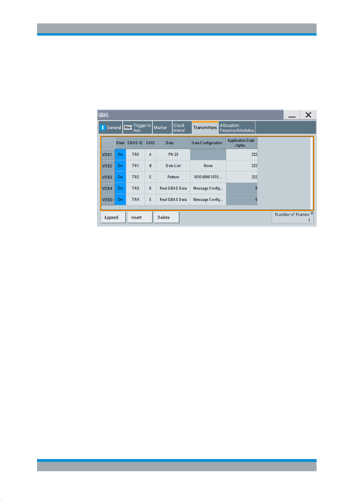
► Select "GBAS > Transmitters".
The dialog comprises the settings, necessary to configure the VHF Data Broadcast
(VDB) signals.
Settings
State..............................................................................................................................20
GBAS ID........................................................................................................................20
SSID..............................................................................................................................21
Data/Data Configuration................................................................................................21
App. Data Length/bytes.................................................................................................21
Number of Frames........................................................................................................ 22
Append, Insert, Delete.................................................................................................. 22
State
Enables the selected VHF Data Broadcast (VDB) transmitter.
Remote command:
[:SOURce<hw>]:BB:GBAS:VDB<ch>:STATe on page 73
GBAS ID
Sets the GBAS ID, that is a four-character (24-bit) alphanumeric field that identifies the
ground station broadcasting the message. Permitted are capital letter, numbers and
"space".
To identify a ground station, the airborne receiver examines the combination of the
GBAS ID and the SSID.
Remote command:
[:SOURce<hw>]:BB:GBAS:VDB<ch>:GID on page 73
20User Manual 1178.9690.02 ─ 03
Page 21

R&S®SMW-K111
GBAS Configuration and Settings
Transmitter Settings
SSID
Sets the station slot identifier SSID/RSID of the ground station.
According to RTCA DO-246D, the SSID is a numeric value from 0 to 7, corresponding
to the letter designation (A through H) of the first time slot assigned to a particular
ground reference station, where slot A = 0 and slot H = 7. All messages in all time slots
employed by a particular ground station use the same SSID.
To identify a ground station, the airborne receiver examines the combination of the
GBAS ID and the SSID.
Remote command:
[:SOURce<hw>]:BB:GBAS:VDB<ch>:SSID on page 73
Data/Data Configuration
Selects the data source for the VDB.
The following standard data sources are available:
●
"All 0, All 1"
An internally generated sequence containing 0 data or 1 data.
●
"PNxx"
An internally generated pseudo-random noise sequence.
●
"Pattern"
An internally generated sequence according to a bit pattern.
Use the "Pattern" box to define the bit pattern.
●
"Data List/Select DList"
A binary data from a data list, internally or externally generated.
Select "Select DList" to access the standard "Select List" dialog.
– Select the "Select Data List > navigate to the list file *.dm_iqd > Select" to
select an existing data list.
– Use the "New" and "Edit" functions to create internally new data list or to edit
an existing one.
– Use the standard "File Manager" function to transfer external data lists to the
instrument.
See also:
●
Section "Modulation Data" in the R&S SMW user manual.
●
Section "File and Data Management" in the R&S SMW user manual.
●
Section "Data List Editor" in the R&S SMW user manual
"Real GBAS Data"
Enables you to configure the content of the GBAS messages.
Select "Data Config > Message Config..." to access the provided settings.
Remote command:
[:SOURce<hw>]:BB:GBAS:VDB<ch>:DATA on page 74
[:SOURce<hw>]:BB:GBAS:VDB<ch>:DATA:DSELection on page 75
[:SOURce<hw>]:BB:GBAS:VDB<ch>:DATA:PATTern on page 75
App. Data Length/bytes
Sets the application data length.
For "Data/Data Configuration > Real GBAS Data", the value of the application data
length is not variable but is automatically set and calculated.
21User Manual 1178.9690.02 ─ 03
Page 22

R&S®SMW-K111
GBAS Configuration and Settings
Message Configuration Settings
Remote command:
[:SOURce<hw>]:BB:GBAS:VDB<ch>:DLENgth on page 74
Number of Frames
Displays the automatically calculated number of frames of the selected VDB.
Remote command:
[:SOURce<hw>]:BB:GBAS:NOFRames? on page 72
Append, Insert, Delete
You can configure up to 8 VDB transmitters. Use the appropriate general functions:
"Append"
Remote command:
[:SOURce<hw>]:BB:GBAS:VDB:APPend on page 72
Adds a new row in the table of VDB transmitters.
"Insert"
Remote command:
[:SOURce<hw>]:BB:GBAS:VDB<ch>:INSert on page 72
"Delete"
Remote command:
[:SOURce<hw>]:BB:GBAS:VDB<ch>:DELete on page 73
Adds a new row above the currently selected one.
Deletes the selected row.
4.3 Message Configuration Settings
Access:
1. Select "GBAS > Transmitters".
2. Select "VDB# > Data > Real GBAS Data"
3. Select "Data Config > Message Config...".
Settings
● Message Type 1 & 11 Settings................................................................................22
● Message Type 2 Settings........................................................................................24
● Message Type 4 Settings........................................................................................32
4.3.1 Message Type 1 & 11 Settings
Differential GNSS is an approach that uses known GNSS reference locations to determine channel correction parameters. The retrieved information is transmitted to other
GNSS receivers to increase the accuracy of their position information.
22User Manual 1178.9690.02 ─ 03
Page 23
R&S®SMW-K111
GBAS Configuration and Settings
Message Configuration Settings
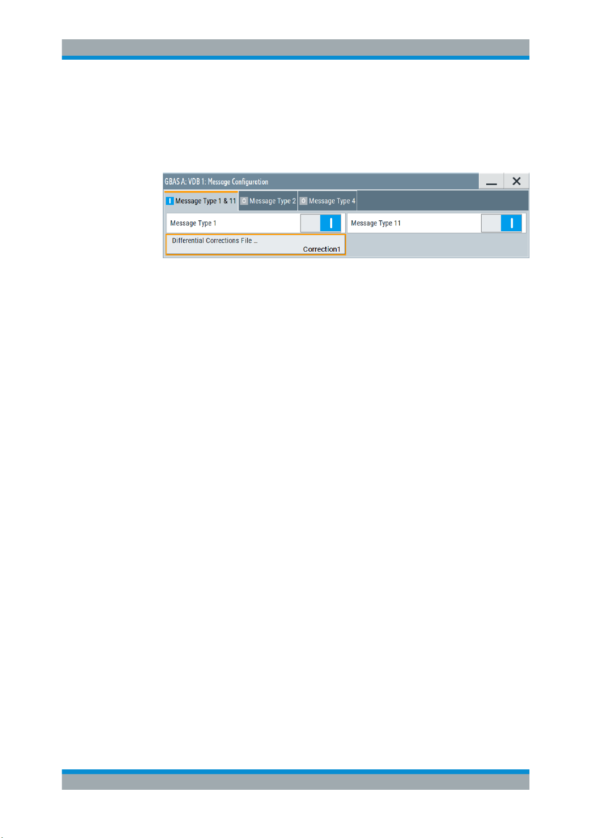
Access:
1. Select "Data Config > Message Config...", see Chapter 4.3, "Message Configura-
tion Settings", on page 22.
2. Select "VDB#:Message Configuration > Message Type 1 & 11"
This dialog comprises settings to manage GBAS differential data.
For step-by-step description of how to load GBAS differential data, see Chapter 6.1,
"Loading Differential GBAS Data", on page 62.
Settings
Meassage Type 1..........................................................................................................23
Meassage Type 11........................................................................................................23
Differential Corrections File ..........................................................................................23
Predefined Files............................................................................................................ 24
Meassage Type 1
Activates the use of message type 1, differential GPS corrections.
Remote command:
[:SOURce<hw>]:BB:GBAS:VDB<ch>:MCONfig:DG:M1STate on page 79
Meassage Type 11
Activates the use of the message type 11, C/A-Code L1, L2 delta corrections.
Remote command:
[:SOURce<hw>]:BB:GBAS:VDB<ch>:MCONfig:DG:M11State on page 79
Differential Corrections File ...
Accesses the "Proprietary File" dialog to select a file containing differential GBAS information.
The differential GBAS file must have the extension *.rs_gbas and file format as
described in Chapter A.2, "GBAS Differential File Format", on page 115.
The differential SCAT-I file must have the extension *.rs_scat and file format as
described in Chapter A.3, "SCAT-I Differential File Format", on page 117.
Select "Predefined Files" to load a predefined file.
Remote command:
For "Mode > GBAS":
[:SOURce<hw>]:BB:GBAS:VDB<ch>:MCONfig:DG:FILE? on page 81
[:SOURce<hw>]:BB:GBAS:VDB<ch>:MCONfig:DG:USER:CATalog? on page 80
[:SOURce<hw>]:BB:GBAS:VDB<ch>:MCONfig:DG:USER:FILE on page 81
23User Manual 1178.9690.02 ─ 03
Page 24

R&S®SMW-K111
GBAS Configuration and Settings
Message Configuration Settings
For "Mode > SCAT-I":
[:SOURce<hw>]:BB:GBAS:VDB<ch>:MCONfig:DG:SFILe? on page 81
[:SOURce<hw>]:BB:GBAS:VDB<ch>:MCONfig:DG:SUSer:CATalog on page 80
[:SOURce<hw>]:BB:GBAS:VDB<ch>:MCONfig:DG:SUSer:FILE on page 80
Predefined Files
Access a list with predefined files.
Remote command:
For "Mode > GBAS":
[:SOURce<hw>]:BB:GBAS:VDB<ch>:MCONfig:DG:PREDefined:CATalog?
on page 80
[:SOURce<hw>]:BB:GBAS:VDB<ch>:MCONfig:DG:PREDefined:FILE
on page 80
For "Mode > SCAT-I":
[:SOURce<hw>]:BB:GBAS:VDB<ch>:MCONfig:DG:SPRedefined:CATalog
on page 80
[:SOURce<hw>]:BB:GBAS:VDB<ch>:MCONfig:DG:SPRedefined:FILE
on page 79
For waypoint files:
[:SOURce<hw>]:BB:GBAS:VDB<ch>:MCONfig:WAYPoint:PREDefined:
CATalog? on page 104
[:SOURce<hw>]:BB:GBAS:VDB<ch>:MCONfig:WAYPoint:PREDefined:FILE
on page 104
4.3.2 Message Type 2 Settings
Access:
1. Select "Data Config > Message Config...", see Chapter 4.3, "Message Configura-
tion Settings", on page 22.
24User Manual 1178.9690.02 ─ 03
Page 25
R&S®SMW-K111
GBAS Configuration and Settings
Message Configuration Settings
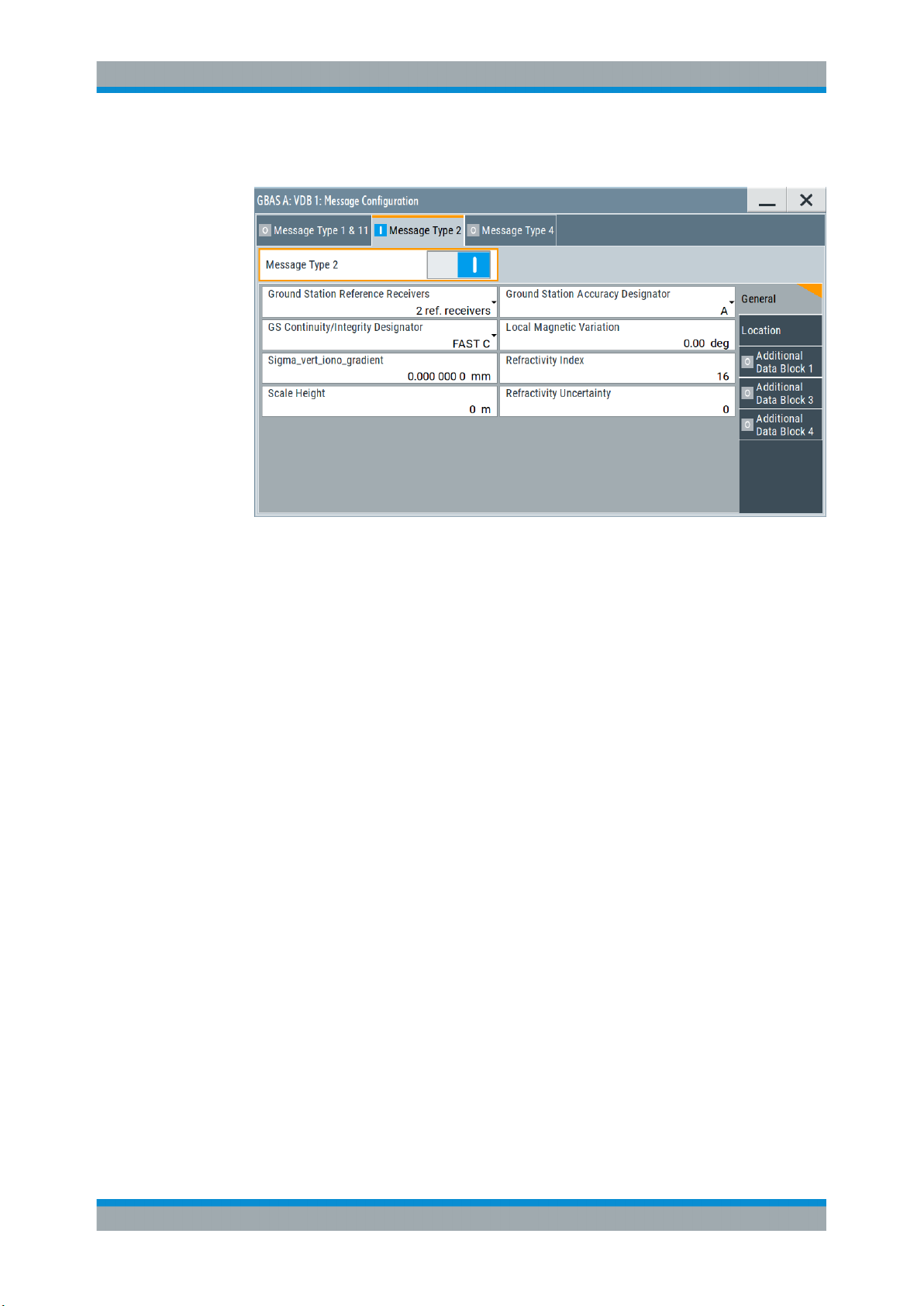
2. Select "VDB#:Message Configuration > Message Type 2".
This dialog comprises settings necessary to configure message type 2 parameters
according to RTCA DO-246D, Table 2.14.
Message type 2 carries information on the exact location as well as other GBAS-related parameters.
Settings
● General Settings..................................................................................................... 25
● Location Settings.....................................................................................................27
● Additional Data Block 1 Settings.............................................................................28
● Additional Data Block 3 Settings.............................................................................30
● Additional Data Block 4 Settings.............................................................................31
4.3.2.1 General Settings
Access:
1. Select "VDB#:Message Configuration > Message Type 2 > General Settings".
2. Select "Message Type 2 > On"
This dialog comprises general settings necessary to configure message type 2
parameter according to RTCA DO-246D, Table 2.14.
Settings
Message Type 2............................................................................................................26
Ground Station Reference Receivers........................................................................... 26
Ground Station Accuracy Designator............................................................................26
Ground Station Continuity/Integrity Designator.............................................................26
25User Manual 1178.9690.02 ─ 03
Page 26

R&S®SMW-K111
GBAS Configuration and Settings
Message Configuration Settings
Local Magnetic Variation............................................................................................... 26
Sigma_vert_iono_gradient............................................................................................ 26
Refractivity Index...........................................................................................................26
Scale Height..................................................................................................................27
Refractivity Uncertainty................................................................................................. 27
Message Type 2
Enables you to configure the parameters of message type 2, according to RTCA
DO-246D, Table 2.14.
Remote command:
[:SOURce<hw>]:BB:GBAS:VDB<ch>:MCONfig:MT2State on page 86
Ground Station Reference Receivers
Selects the number of the GNSS reference receivers installed in this system.
Remote command:
[:SOURce<hw>]:BB:GBAS:VDB<ch>:MCONfig:GSRReceivers on page 82
Ground Station Accuracy Designator
Selects the letter designator indicating the minimum signal-in-space accuracy performance provided by the ground station.
Remote command:
[:SOURce<hw>]:BB:GBAS:VDB<ch>:MCONfig:GSADesignator on page 82
Ground Station Continuity/Integrity Designator
Selects the numerical designator that indicates the operational status of GBAS.
Remote command:
[:SOURce<hw>]:BB:GBAS:VDB<ch>:MCONfig:GCID on page 82
Local Magnetic Variation
Sets the published local magnetic variation at the differential reference point. A positive
value represents an east variation (clockwise from true north).
Remote command:
[:SOURce<hw>]:BB:GBAS:VDB<ch>:MCONfig:LMVariation on page 82
Sigma_vert_iono_gradient
Sets the parameter σ
vert_iono_gradient
, that is the standard deviation of a normal distribu-
tion associated with the residual ionospheric uncertainty due to spatial decorrelation.
Remote command:
[:SOURce<hw>]:BB:GBAS:VDB<ch>:MCONfig:SVIGradient on page 85
Refractivity Index
Sets the estimated tropospheric refractivity index NR at the reference point.
Remote command:
[:SOURce<hw>]:BB:GBAS:VDB<ch>:MCONfig:RFINdex on page 84
26User Manual 1178.9690.02 ─ 03
Page 27
R&S®SMW-K111
4.3.2.2 Location Settings
GBAS Configuration and Settings
Message Configuration Settings
Scale Height
Sets the parameter scale height (h0), used for scaling the tropospheric refractivity as a
function of differential altitude.
Remote command:
[:SOURce<hw>]:BB:GBAS:VDB<ch>:MCONfig:SHEight on page 85
Refractivity Uncertainty
Sets the parameter σN, that is the standard deviation of a normal distribution associated with the residual tropospheric uncertainty.
Remote command:
[:SOURce<hw>]:BB:GBAS:VDB<ch>:MCONfig:RUNCertainty on page 85
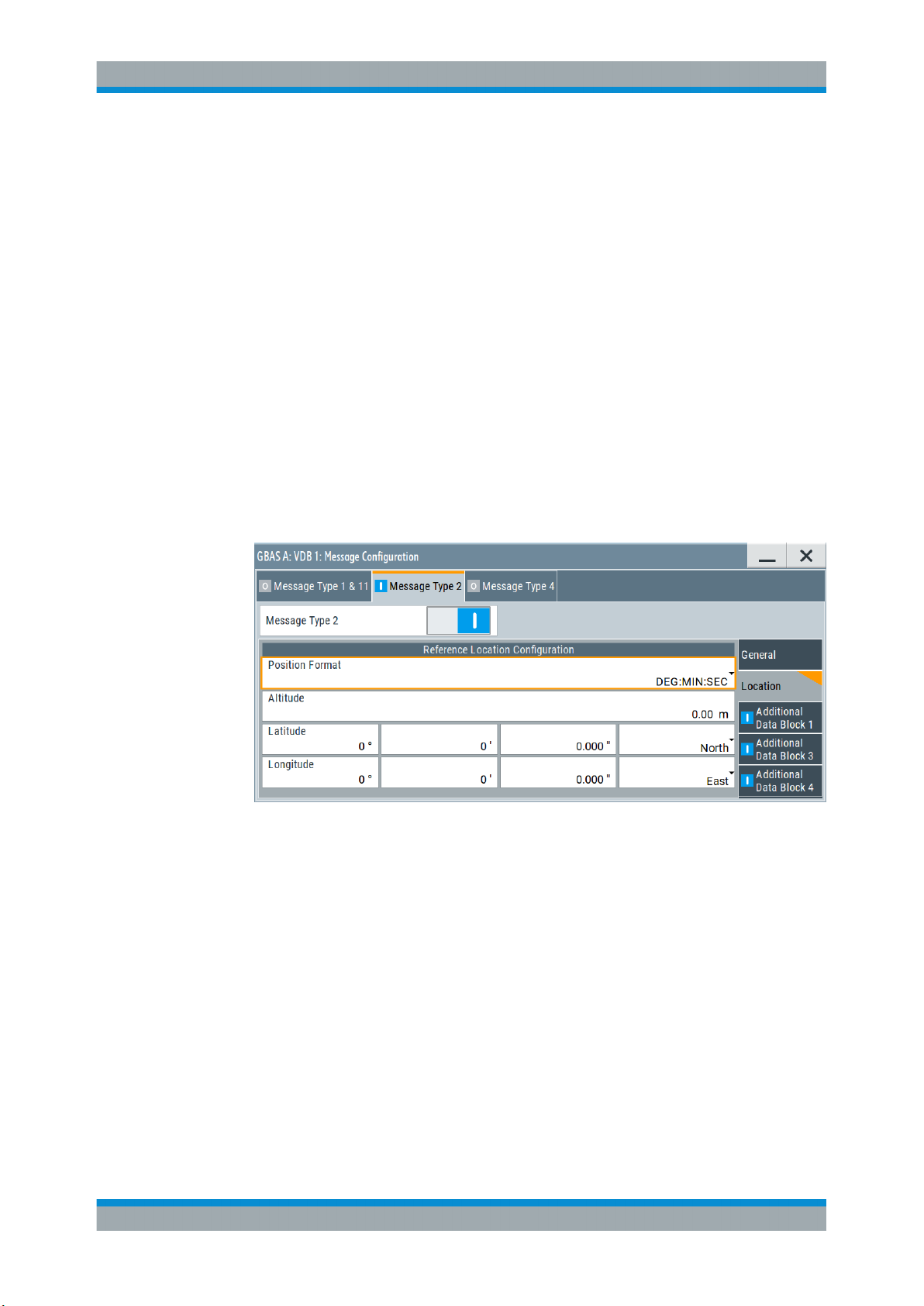
Access:
► Select "VDB#:Message Configuration > Message Type 2 > Location Settings".
This dialog comprises location settings necessary to configure message type 2
parameter according to RTCA DO-246D, Table 2.14.
Settings
Reference Location Configuration.................................................................................27
Reference Location Configuration
The coordinates of the ground station reference point are defined in WGS84 coordinates. In this coordinate system, a location is identified by three coordinates, the altitude, the latitude and the longitude. The last two can be displayed in decimal or DMS
format. Use the parameter "Position Format" to select the display format.
27User Manual 1178.9690.02 ─ 03
Page 28
R&S®SMW-K111
GBAS Configuration and Settings
Message Configuration Settings
Table 4-2: Reference location configuration
Parameter Description
"Position Format" Sets the format in which the Latitude and Longitude are displayed.
"Altitude" Sets the altitude of the ground station reference point, that is the height above
"Latitude" Sets the latitude of the ground station reference point.
"Longitude" Sets the longitude of the ground station reference point.
●
"DEG:MIN:SEC"
The display format is Degree:Minute:Second and Direction, i.e.
XX°XX'XX.XX" Direction, where direction can be North/South and
East/West.
●
"Decimal Degree"
The display format is decimal degree, i.e. +/-XX.XXXXX°, where "+"
indicates North and East and "-" indicates South and West.
the ellipsoid (HAE) altitude.
Remote command:
To enter the coordinates in Degree:Minute:Second format:
[:SOURce<hw>]:BB:GBAS:VDB<ch>:MCONfig:LOCation:COORdinates:DMS
on page 83
To enter the coordinates in decimal degree format
[:SOURce<hw>]:BB:GBAS:VDB<ch>:MCONfig:LOCation:COORdinates:
DECimal on page 83
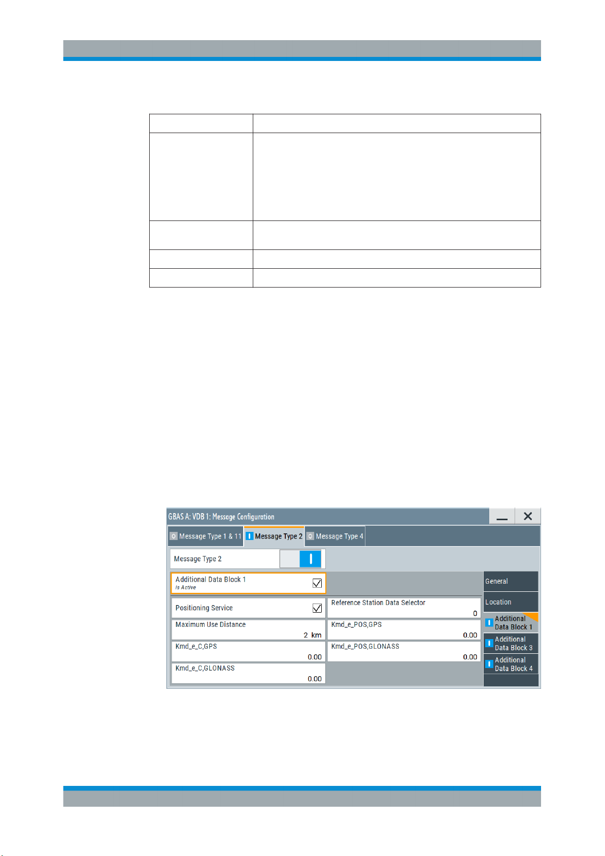
4.3.2.3 Additional Data Block 1 Settings
Access:
► Select "VDB#:Message Configuration > Message Type 2 > Additional Data Block
1".
This dialog comprises additional data block 1 settings necessary to configure message type 2 parameter according to RTCA DO-246D, Table 2.14.
28User Manual 1178.9690.02 ─ 03
Page 29

R&S®SMW-K111
GBAS Configuration and Settings
Message Configuration Settings
Settings
Additional Data Block 1.................................................................................................29
Positioning Service........................................................................................................29
Reference Station Data Selector...................................................................................29
Maximum User Distance...............................................................................................29
Kmd_e_C, GPS/GLONASS.......................................................................................... 29
Kmd_e_POS GPS/CLONASS...................................................................................... 29
Additional Data Block 1
Enables you to configure the additional data block 1.
Remote command:
[:SOURce<hw>]:BB:GBAS:VDB<ch>:MCONfig:ADB1:STATe on page 86
Positioning Service
Selects if the GBAS positioning service is supported.
Remote command:
[:SOURce<hw>]:BB:GBAS:VDB<ch>:MCONfig:PSERvice:STATe on page 88
Reference Station Data Selector
Requires "Positioning Service > On".
Sets the numerical identifier for selecting the ground subsystem.
Remote command:
[:SOURce<hw>]:BB:GBAS:VDB<ch>:MCONfig:RSDSelector on page 88
Maximum User Distance
Sets the maximum distance from the reference point for which the integrity is assured.
Remote command:
[:SOURce<hw>]:BB:GBAS:VDB<ch>:MCONfig:MUDistance on page 88
Kmd_e_C, GPS/GLONASS
Sets the ephemeris missed detection parameter (Kmd_e), category I precision
approach and approach with vertical guidance (APV). This is a multiplier considered
when calculating the ephemeris error position bound for the category I precision
approach and APV. It is derived from the probability that a detection is missed because
of an ephemeris error in a GPS/GLONASS satellite.
Remote command:
[:SOURce<hw>]:BB:GBAS:VDB<ch>:MCONfig:KCGLonass on page 87
[:SOURce<hw>]:BB:GBAS:VDB<ch>:MCONfig:KCGPs on page 87
Kmd_e_POS GPS/CLONASS
Sets the ephemeris missed detection parameter (Kmd_e), GBAS positioning service.
This is a multiplier considered when calculating the ephemeris error position bound for
the GBAS positioning. It is derived from the probability that a detection is missed
because of an ephemeris error in a GPS/GLONASS satellite.
29User Manual 1178.9690.02 ─ 03
Page 30
R&S®SMW-K111
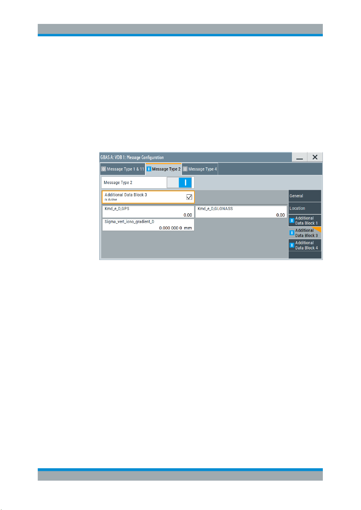
4.3.2.4 Additional Data Block 3 Settings
GBAS Configuration and Settings
Message Configuration Settings
Remote command:
[:SOURce<hw>]:BB:GBAS:VDB<ch>:MCONfig:KPGLonass on page 88
[:SOURce<hw>]:BB:GBAS:VDB<ch>:MCONfig:KPGPs on page 88
Access:
► Select "VDB#:Message Configuration > Message Type 2 > Additional Data Block
3".
This dialog comprises additional data block 3 settings necessary to configure message type 2 parameter according to RTCA DO-246D, Table 2.14.
Settings
Additional Data Block 3.................................................................................................30
Kmd_e_D, GPS/ Kmd_e_D, GLONASS....................................................................... 30
Sigma_vert_iono_gradient_ID.......................................................................................31
Additional Data Block 3
Enables you to configure the parameters of the additional block 3, containing the
GBAS approach service type (GAST) D parameters.
Remote command:
[:SOURce<hw>]:BB:GBAS:VDB<ch>:MCONfig:ADB3:STATe on page 87
Kmd_e_D, GPS/ Kmd_e_D, GLONASS
Sets the ephemeris missed detection parameter (Kmd_e), GAST D. This is a multiplier
considered when calculating the ephemeris error position bound for GAST D. It is
derived from the probability that a detection is missed because of an ephemeris error
in a GPS/GLONASS satellite.
Remote command:
[:SOURce<hw>]:BB:GBAS:VDB<ch>:MCONfig:KDGLonass on page 89
[:SOURce<hw>]:BB:GBAS:VDB<ch>:MCONfig:KDGPs on page 89
30User Manual 1178.9690.02 ─ 03
Page 31

R&S®SMW-K111
4.3.2.5 Additional Data Block 4 Settings
GBAS Configuration and Settings
Message Configuration Settings
Sigma_vert_iono_gradient_ID
Sets the standard deviation of a normal distribution connected to the residual ionospheric uncertainty which is caused by spatial decorrelation.
Remote command:
[:SOURce<hw>]:BB:GBAS:VDB<ch>:MCONfig:SVID on page 89
Access:
► Select "VDB#:Message Configuration > Message Type 2 > Additional Data Block
4".
This dialog comprises additional data block 4 settings necessary to configure message type 2 parameter according to RTCA DO-246D, Table 2.14.
Settings
Additional Data Block 4.................................................................................................31
Slot Group Definition.....................................................................................................31
Additional Data Block 4
Enables you to configure the parameters of the additional block 4, containing the VDB
authentication parameters.
Remote command:
[:SOURce<hw>]:BB:GBAS:VDB<ch>:MCONfig:ADB4:STATe on page 87
Slot Group Definition
Specifies which slots are used by the ground station.
Remote command:
[:SOURce<hw>]:BB:GBAS:VDB<ch>:MCONfig:SGDefinition:A:STATe
on page 89
[:SOURce<hw>]:BB:GBAS:VDB<ch>:MCONfig:SGDefinition:B:STATe
on page 89
31User Manual 1178.9690.02 ─ 03
Page 32

R&S®SMW-K111
4.3.3 Message Type 4 Settings
GBAS Configuration and Settings
Message Configuration Settings
[:SOURce<hw>]:BB:GBAS:VDB<ch>:MCONfig:SGDefinition:C:STATe
on page 89
[:SOURce<hw>]:BB:GBAS:VDB<ch>:MCONfig:SGDefinition:D:STATe
on page 89
[:SOURce<hw>]:BB:GBAS:VDB<ch>:MCONfig:SGDefinition:E:STATe
on page 89
[:SOURce<hw>]:BB:GBAS:VDB<ch>:MCONfig:SGDefinition:F:STATe
on page 89
[:SOURce<hw>]:BB:GBAS:VDB<ch>:MCONfig:SGDefinition:G:STATe
on page 90
[:SOURce<hw>]:BB:GBAS:VDB<ch>:MCONfig:SGDefinition:H:STATe
on page 90
Access:
1. Select "Data Config > Message Config...", see Chapter 4.3, "Message Configura-
tion Settings", on page 22.
2. Select "VDB#:Message Configuration > Message Type 4"
The dialog comprises settings necessary to configure message type 4 parameters.
For "Mode > GBAS", the settings conform with specification RTCA DO-246D.
For "Mode > SCAT-I", the settings conform with specification RTCA DO-217H.
According to the RTCA DO-246D, the message type 4 contains one or more data sets
that contain approach data, associated vertical/lateral alert limits, and/or the Terminal
Area Path (TAP).
32User Manual 1178.9690.02 ─ 03
Page 33

R&S®SMW-K111
4.3.3.1 General Settings
GBAS Configuration and Settings
Message Configuration Settings
You can configure the Final Approach Segment (FAS) data set, the TAP data set or
both.
TAP data is not available for "Mode > SCAT-I".
Settings
● General Settings..................................................................................................... 33
● FAS Data Settings...................................................................................................34
● TAP Data Settings...................................................................................................37
● Location Settings.....................................................................................................40
Access:
► Select "VDB#:Message Configuration > Message Type 4".
This dialog comprises general settings like enabling the configuration of message
type 4 parameters.
Settings
Message Type 4............................................................................................................33
Message Type 4
Enables you to configure the parameters of message type 4, according to RTCA
DO-246D, Table 2.18.
Remote command:
[:SOURce<hw>]:BB:GBAS:VDB<ch>:MCONfig:MT4State on page 91
33User Manual 1178.9690.02 ─ 03
Page 34

R&S®SMW-K111
4.3.3.2 FAS Data Settings
GBAS Configuration and Settings
Message Configuration Settings
Access:
► Select "VDB#:Message Configuration > Message Type 4 > FAS Data".
This dialog comprises FAS data settings necessary to configure message type 4
parameter according to RTCA DO-246D, Table 2.14.
FAS data is required for both "GBAS" (LAAS) and "SCAT-I" header information modes.
Unless stated otherwise, the settings below hold for both modes.
Settings
FAS Data Set................................................................................................................ 34
Plan View/Profile View Parameters...............................................................................35
Airport ID.......................................................................................................................36
Runway Number........................................................................................................... 36
Runway Letter...............................................................................................................36
Approach Performance Designator...............................................................................36
Route Indicator..............................................................................................................36
Reference Path Data Selector...................................................................................... 36
Reference Path ID.........................................................................................................37
Course Width at Threshold........................................................................................... 37
Delta_Length Offset...................................................................................................... 37
FAS Vertical Alert Limit / Approach Status....................................................................37
FAS Lateral Alert Limit / Approach Status.....................................................................37
FAS Data Set
Requires "Mode > GBAS" (LAAS) header information.
Enables you to configure the parameters of the Final Approach Segment (FAS) data
set.
34User Manual 1178.9690.02 ─ 03
Page 35

R&S®SMW-K111
GBAS Configuration and Settings
Message Configuration Settings
Provided are the parameters necessary to configure a single precision approach. The
FAS path is a line in space that defines the path an airplane follows on its final
approach. This line is defined by the Landing Threshold Point/Fictitious Threshold
Point (LTP/FTP), Flight Path Alignment Point (FPAP), Threshold Crossing Height
(TCH), and the Glide Path Angle (GPA).
The dialog displays also two graphs, a "Plan View" and a "Profile View", to visualize a
typical final approach path.
Figure 4-1: Final Approach Segment (FAS) diagram, according to RTCA DO-246D
LTP/FTP = Landing Threshold Point/Fictitious Threshold Point; point at the center of the landing runway,
defined by its WGS84 coordinates
GPIP = Glide Path Intercept Point; the point where the final approach path intercepts the local level plane
FPAP = Flight Path Alignment Point; point at the end of the runway that in conjunction with the LTP/FTP
defines the geodesic plane of the precision final approach, landing and flight path.
TCH = Threshold Crossing Height
GAP = Glide Path Angle; angle at the TCH that describes the intended angle of descent at the final
approach path.
Remote command:
[:SOURce<hw>]:BB:GBAS:VDB<ch>:MCONfig:FDSState on page 91
Plan View/Profile View Parameters
Requires "Mode > GBAS" (LAAS) header information.
The following parameters define the approach path (see also Figure 4-1):
"Glide Path Angle"
Sets the angle of the FAS path (glide path) with respect to the horizontal plane tangent to the WGS84 ellipsoid at the LTP/FTP.
Remote command:
[:SOURce<hw>]:BB:GBAS:VDB<ch>:MCONfig:GPANgle on page 98
35User Manual 1178.9690.02 ─ 03
Page 36

R&S®SMW-K111
GBAS Configuration and Settings
Message Configuration Settings
"TCH"
Remote command:
[:SOURce<hw>]:BB:GBAS:VDB<ch>:MCONfig:ATCHeight on page 92
[:SOURce<hw>]:BB:GBAS:VDB<ch>:MCONfig:ATUSelector on page 92
"LTP/FTP Height"
Remote command:
[:SOURce<hw>]:BB:GBAS:VDB<ch>:MCONfig:LFLocation:HEIGht
on page 100
Airport ID
Sets the airport identification as three or four alphanumeric characters used to designate airport facilities. Permitted are upper letters, numbers and "space".
Remote command:
[:SOURce<hw>]:BB:GBAS:VDB<ch>:MCONfig:AID on page 91
Runway Number
Sets the approach runway number.
Remote command:
[:SOURce<hw>]:BB:GBAS:VDB<ch>:MCONfig:RNUMber on page 100
Sets the threshold crossing height (TCH) , that is the height of the
FAS path above the LTP/FTP defined in either feet or meters.
Sets the height of the LTP/FTP above the WGS84 ellipsoid.
Runway Letter
Sets the runway letter, to distinguish between parallel runways. The conventional designation is used.
Remote command:
[:SOURce<hw>]:BB:GBAS:VDB<ch>:MCONfig:RLETter on page 100
Approach Performance Designator
Requires "Mode > GBAS" (LAAS) header information.
Sets the general information about the approach design. The conventional designation
is used.
Remote command:
[:SOURce<hw>]:BB:GBAS:VDB<ch>:MCONfig:APDesignator on page 92
Route Indicator
Sets the route indicator, that is a single alphabetic character used to differentiate
between multiple approaches to the same runway end. Allowed are the upper case letters, excluding “I” and “O”, or the “space” character.
Remote command:
[:SOURce<hw>]:BB:GBAS:VDB<ch>:MCONfig:RUINdicator on page 101
Reference Path Data Selector
Sets the reference path data selector (RPDS), that is a numerical identifier that is
unique on a frequency in the broadcast region and used to select the FAS.
36User Manual 1178.9690.02 ─ 03
Page 37

R&S®SMW-K111
GBAS Configuration and Settings
Message Configuration Settings
Remote command:
[:SOURce<hw>]:BB:GBAS:VDB<ch>:MCONfig:RPDF on page 101
Reference Path ID
Sets the reference path identifier as three or four alphanumeric characters used to designate the reference path.
Remote command:
[:SOURce<hw>]:BB:GBAS:VDB<ch>:MCONfig:RPIF on page 101
Course Width at Threshold
Requires "Mode > GBAS" (LAAS) header information.
Sets the lateral displacement from the path defined by the FAS at the LTP/FTP at
which full-scale course deviation indicator (CDI) deflection is attained.
Remote command:
[:SOURce<hw>]:BB:GBAS:VDB<ch>:MCONfig:CWAThreshold on page 92
Delta_Length Offset
Requires "Mode > GBAS" (LAAS) header information.
Sets the parameter delta length (ΔLength) offset, that is the distance from the stop end
of the runway to the FPAP.
Remote command:
[:SOURce<hw>]:BB:GBAS:VDB<ch>:MCONfig:DLOFfset on page 96
FAS Vertical Alert Limit / Approach Status
Sets the value of the broadcast vertical alert limit.
Remote command:
[:SOURce<hw>]:BB:GBAS:VDB<ch>:MCONfig:FVAA on page 97
FAS Lateral Alert Limit / Approach Status
Sets the value of the broadcast lateral alert limit.
Remote command:
[:SOURce<hw>]:BB:GBAS:VDB<ch>:MCONfig:FLAA on page 97
4.3.3.3 TAP Data Settings
Requires "Mode > GBAS" (LAAS) header information.
37User Manual 1178.9690.02 ─ 03
Page 38

R&S®SMW-K111
GBAS Configuration and Settings
Message Configuration Settings
Access:
► Select "VDB#:Message Configuration > Message Type 4 > TAP Data".
This dialog comprises TAP data settings necessary to configure message type 4
parameter according to RTCA DO-246D, Table 2.14.
Settings
TAP Data Set.................................................................................................................38
Reference Path Data Selector...................................................................................... 38
Reference Path ID.........................................................................................................39
Number of Path Points - N............................................................................................ 39
Waypoint File.................................................................................................................39
Predefined Files............................................................................................................ 39
FAS RPDS or Continuation Link................................................................................... 40
TAP Vertical Alert Limit / Status.....................................................................................40
TAP Lateral Alert Limit / Status..................................................................................... 40
TAP Data Set
Enables you to configure the parameters of the Terminal Area Path (TAP) data set.
A TAP defines the initial fix (IF), track-to-fix (TF) and radius-to-fix (RF) legs and pro-
vides additional support for terminal area operations.
Remote command:
[:SOURce<hw>]:BB:GBAS:VDB<ch>:MCONfig:TDSState on page 102
Reference Path Data Selector
Sets the reference path data selector.
This parameter is a numerical identifier that is unique on a frequency in the broadcast
region and used to select the TAP.
Remote command:
[:SOURce<hw>]:BB:GBAS:VDB<ch>:MCONfig:RPDT on page 102
38User Manual 1178.9690.02 ─ 03
Page 39

R&S®SMW-K111
GBAS Configuration and Settings
Message Configuration Settings
Reference Path ID
Sets the reference path identifier as three or four alphanumeric characters used to designate the reference path.
Remote command:
[:SOURce<hw>]:BB:GBAS:VDB<ch>:MCONfig:RPIT on page 103
Number of Path Points - N
Indicates the total number of path points included in this TAP.
Remote command:
[:SOURce<hw>]:BB:GBAS:VDB<ch>:MCONfig:NOPPoint on page 102
Waypoint File
Accesses the "Select Waypoint File" dialog to select predefined or user-defined waypoint files.
A waypoint file is description of a moving scenario, like, for example, a sequence of
positions. A waypoint file must have the extension *.txt and file format as described
in Chapter A.1, "Waypoint File Format", on page 115.
Use the "Predefined Files" function, to load a predefined file.
Remote command:
[:SOURce<hw>]:BB:GBAS:VDB<ch>:MCONfig:WAYPoint:PREDefined:
CATalog? on page 104
[:SOURce<hw>]:BB:GBAS:VDB<ch>:MCONfig:WAYPoint:USER:CATalog?
on page 104
[:SOURce<hw>]:BB:GBAS:VDB<ch>:MCONfig:WAYPoint:PREDefined:FILE
on page 104
[:SOURce<hw>]:BB:GBAS:VDB<ch>:MCONfig:WAYPoint:USER:FILE
on page 104
[:SOURce<hw>]:BB:GBAS:VDB<ch>:MCONfig:WAYPoint:FILE? on page 105
Predefined Files
Access a list with predefined files.
Remote command:
For "Mode > GBAS":
[:SOURce<hw>]:BB:GBAS:VDB<ch>:MCONfig:DG:PREDefined:CATalog?
on page 80
[:SOURce<hw>]:BB:GBAS:VDB<ch>:MCONfig:DG:PREDefined:FILE
on page 80
For "Mode > SCAT-I":
[:SOURce<hw>]:BB:GBAS:VDB<ch>:MCONfig:DG:SPRedefined:CATalog
on page 80
[:SOURce<hw>]:BB:GBAS:VDB<ch>:MCONfig:DG:SPRedefined:FILE
on page 79
For waypoint files:
[:SOURce<hw>]:BB:GBAS:VDB<ch>:MCONfig:WAYPoint:PREDefined:
CATalog? on page 104
[:SOURce<hw>]:BB:GBAS:VDB<ch>:MCONfig:WAYPoint:PREDefined:FILE
on page 104
39User Manual 1178.9690.02 ─ 03
Page 40

R&S®SMW-K111
GBAS Configuration and Settings
Message Configuration Settings
FAS RPDS or Continuation Link
Sets the FAS reference path data selector (RPDS) or the continuation link. Continuation link is the RPDS for the next segment that is a continuation of the previous segment.
Remote command:
[:SOURce<hw>]:BB:GBAS:VDB<ch>:MCONfig:FRCLink on page 102
TAP Vertical Alert Limit / Status
Requires "Mode > GBAS" (LAAS) header information.
Sets the value of the broadcast vertical alert limit.
Remote command:
[:SOURce<hw>]:BB:GBAS:VDB<ch>:MCONfig:TVAS on page 103
TAP Lateral Alert Limit / Status
Requires "Mode > GBAS" (LAAS) header information.
Sets the value of the broadcast lateral alert limit.
Remote command:
[:SOURce<hw>]:BB:GBAS:VDB<ch>:MCONfig:TLAS on page 103
4.3.3.4 Location Settings
Access:
► Select "VDB#:Message Configuration > Message Type 4 > Location".
This dialog comprises location data settings necessary to configure message type
4 parameter according to RTCA DO-246D, Table 2.14.
For "Mode > GBAS" (LAAS) header information, configure LTP/FTP Location Configu-
ration and Delta_FPAP Location Configuration settings.
40User Manual 1178.9690.02 ─ 03
Page 41

R&S®SMW-K111
GBAS Configuration and Settings
Message Configuration Settings
For "Mode > SCAT-I" header information, configure DP Location Configuration and
Delta_DERP Location Configuration settings.
Settings
LTP/FTP Location Configuration................................................................................... 41
Delta_FPAP Location Configuration..............................................................................41
DP Location Configuration............................................................................................ 42
Delta_DERP Location Configuration.............................................................................43
LTP/FTP Location Configuration
Requires "Mode > GBAS" (LAAS) header information.
The coordinates of the LTP/FTP are defined in WGS84 coordinates. In this coordinate
system, a location is identified by three coordinates, the altitude, the latitude and the
longitude. The last two can be displayed in decimal or DMS format. Use the parameter
"Position Format" to select the display format.
Use the parameter LTP/FTP Height to define the altitude.
Table 4-3: LTP/FTP location configuration
Parameter Description
"Position Format" Sets the format in which the Latitude and Longitude are displayed.
"Latitude" Sets the latitude of the LTP/FTP in arc seconds.
"Longitude" Sets the longitude of the LTP/FTP in arc seconds.
●
"DEG:MIN:SEC"
The display format is Degree:Minute:Second and Direction, i.e.
XX°XX'XX.XX" Direction, where direction can be North/South and
East/West.
●
"Decimal Degree"
The display format is decimal degree, i.e. +/-XX.XXXXX°, where "+"
indicates North and East and "-" indicates South and West.
Remote command:
To enter the coordinates in Degree:Minute:Second format:
[:SOURce<hw>]:BB:GBAS:VDB<ch>:MCONfig:LFLocation:COORdinates:DMS
on page 99
To enter the coordinates in decimal degree format:
[:SOURce<hw>]:BB:GBAS:VDB<ch>:MCONfig:LFLocation:COORdinates:
DECimal on page 98
Delta_FPAP Location Configuration
Requires "Mode > GBAS" (LAAS) header information.
The Delta FPAD (ΔFPAD) represents the difference of latitude/longitude of the runway
Flight Path Alignment Point (FPAP) from the LTP/FTP.
The Delta FPAD coordinates are defined in WGS84 coordinates. In this coordinate sys-
tem, a location is identified by three coordinates, the altitude, the latitude and the longitude. The last two can be displayed in decimal or DMS format. Use the parameter
"Position Format" to select the display format.
41User Manual 1178.9690.02 ─ 03
Page 42

R&S®SMW-K111
GBAS Configuration and Settings
Message Configuration Settings
Table 4-4: Delta_FPAP location configuration
Parameter Description
"Position Format" Sets the format in which the Latitude and Longitude are displayed.
"Latitude" Sets the difference of latitude of the FPAP in arc seconds.
"Longitude" Sets the difference of longitude of the FPAP in arc seconds.
●
"DEG:MIN:SEC"
The display format is Degree:Minute:Second and Direction, i.e.
XX°XX'XX.XX" Direction, where direction can be North/South and
East/West.
●
"Decimal Degree"
The display format is decimal degree, i.e. +/-XX.XXXXX°, where "+"
indicates North and East and "-" indicates South and West.
Positive values indicate the FPAP latitude north of LTP/FTP latitude.
Positive values indicate the FPAP longitude east of LTP/FTP longitude.
Remote command:
To enter the coordinates in Degree:Minute:Second format:
[:SOURce<hw>]:BB:GBAS:VDB<ch>:MCONfig:DFLocation:COORdinates:DMS
on page 95
To enter the coordinates in decimal degree format:
[:SOURce<hw>]:BB:GBAS:VDB<ch>:MCONfig:DFLocation:COORdinates:
DECimal on page 94
DP Location Configuration
Requires "Mode > SCAT-I" header information.
The DP represents the threshold datum point (DP). The point is the tangential point
between the horizontal plane and WGS84 ellipsoid.
The DP coordinates are defined in WGS-84 coordinates. In this coordinate system, a
location is identified by three coordinates, the altitude, the latitude and the longitude.
The last two can be displayed in decimal or DMS format. Use the parameter "Position
Format" to select the display format.
Table 4-5: DP location configuration
Parameter Description
"Position Format" Sets the format in which the Latitude and Longitude are displayed.
"Latitude" Sets the difference of latitude of the DP in arc seconds.
"Longitude" Sets the difference of longitude of the DP in arc seconds.
●
"DEG:MIN:SEC"
The display format is Degree:Minute:Second and Direction, i.e.
XX°XX'XX.XX" Direction, where direction can be North/South and
East/West.
●
"Decimal Degree"
The display format is decimal degree, i.e. +/-XX.XXXXX°, where "+"
indicates North and East and "-" indicates South and West.
Positive values indicate the DP latitude north of TCP latitude.
Positive values indicate the DP longitude east of TCP longitude.
42User Manual 1178.9690.02 ─ 03
Page 43

R&S®SMW-K111
GBAS Configuration and Settings
Message Configuration Settings
Remote command:
To enter the coordinates in Degree:Minute:Second format:
[:SOURce<hw>]:BB:GBAS:VDB<ch>:MCONfig:FDB<st>:DPLocation:
COORdinates:DMS on page 96
To enter the coordinates in decimal degree format:
[:SOURce<hw>]:BB:GBAS:VDB<ch>:MCONfig:FDB<st>:DPLocation:
COORdinates:DECimal on page 96
Delta_DERP Location Configuration
Requires "Mode > SCAT-I" header information.
Sets the departure end of runway point (DERP) or stop-end point.
This point is typically located on the runway centerline at the end of the runway.
The Delta DERP coordinates are defined in WGS84 coordinates. In this coordinate
system, a location is identified by three coordinates, the altitude, the latitude and the
longitude. The last two can be displayed in decimal or DMS format. Use the parameter
"Position Format" to select the display format.
Table 4-6: Delta_DERP location configuration
Parameter Description
"Position Format" Sets the format in which the Latitude and Longitude are displayed.
"Latitude" Sets the difference of latitude of the Delta_DERP in arc seconds.
"Longitude" Sets the difference of longitude of the Delta_DERP in arc seconds.
●
"DEG:MIN:SEC"
The display format is Degree:Minute:Second and Direction, i.e.
XX°XX'XX.XX" Direction, where direction can be North/South and
East/West.
●
"Decimal Degree"
The display format is decimal degree, i.e. +/-XX.XXXXX°, where "+"
indicates North and East and "-" indicates South and West.
Positive values indicate the Delta_DERP latitude north of LTP/FTP latitude.
Positive values indicate the Delta_DERP longitude east of LTP/FTP longitude.
Remote command:
To enter the coordinates in Degree:Minute:Second format:
[:SOURce<hw>]:BB:GBAS:VDB<ch>:MCONfig:FDB<st>:DDLocation:
COORdinates:DMS on page 93
To enter the coordinates in decimal degree format:
[:SOURce<hw>]:BB:GBAS:VDB<ch>:MCONfig:FDB<st>:DDLocation:
COORdinates:DECimal on page 93
43User Manual 1178.9690.02 ─ 03
Page 44

R&S®SMW-K111
4.4 Allocation and Frequency/Scheduling Settings
4.4.1 Allocation Settings
GBAS Configuration and Settings
Allocation and Frequency/Scheduling Settings
Access:
► Select "GBAS > Allocation".
This dialog comprises the allocation and scheduling settings of the VDB transmitters and frequency channels.
Settings
● Allocation Settings...................................................................................................44
● Scheduling Settings................................................................................................ 45
Access:
► Select "GBAS > Allocation".
This dialog comprises the settings, necessary to configure the allocation of the
VDB transmitters "VDB#" on the selected frequency number "FN#".
Allocation Table
Comprises the allocation of the VDB transmitters "VDB#" on the selected frequency
number "FN#".
There is one table row for each VDB transmitter as configured in Chapter 4.2, "Trans-
mitter Settings", on page 20.
Scheduling ← Allocation Table
Configure the time domain scheduling of VDB transmitters on the selected frequency
number.
44User Manual 1178.9690.02 ─ 03
Page 45

R&S®SMW-K111
GBAS Configuration and Settings
Allocation and Frequency/Scheduling Settings
Configuration requires, that the VDB transmitter is mapped to the frequency number.
Access scheduling settings via the icon
on page 45.
FN -5 to 5 ← Allocation Table
Displays the frequency number and defines the frequency band the corresponding
VDB is using, see "Carrier frequencies and frequency channels" on page 11.
Remote command:
[:SOURce<hw>]:BB:GBAS:VDB<ch>:FNUMber on page 74
Map VDB# to FN# ← Allocation Table
The mapping of the VDB transmitters on frequency numbers "FN -5 to FN 5" is represented as a matrix. Listed are VDB transmitters and their "GBAS ID", as configured in
Chapter 4.2, "Transmitter Settings", on page 20.
, see Chapter 4.4.2, "Scheduling Settings",
A blue matrix element activates the VDB transmitter "VDB#" on the frequency number "FN#". Activation of one VDB transmitter on more than one frequency number is
not possible.
4.4.2 Scheduling Settings
Access:
1. Select "GBAS > Allocation".
45User Manual 1178.9690.02 ─ 03
Page 46

R&S®SMW-K111
GBAS Configuration and Settings
Allocation and Frequency/Scheduling Settings
2.
Select "Allocation > Allocation Table > Scheduling > Configuration" via the icon .
This dialog comprises settings necessary to configure the time domain scheduling
of the VDB transmitters on the selected frequency.
The transmission is based on TDMA and hence on one particular frequency you
can allocate only one VDB transmitter per one time slot (Slot A..H).
For more information, see "Broadcast timing structure" on page 12.
Settings
SSID..............................................................................................................................46
Slot A to H.....................................................................................................................47
└ State................................................................................................................47
└ Power Offset...................................................................................................47
Show/Hide Message Output Rate.................................................................................47
Message Scheduling Table........................................................................................... 47
└ Frame Cycle....................................................................................................48
└ Frame Offset...................................................................................................48
└ Slot..................................................................................................................48
└ Max Bytes per Slot..........................................................................................48
└ Link Pair..........................................................................................................48
└ Bytes Overload > !!!........................................................................................ 49
└ Message Config..............................................................................................49
SSID
Sets the station slot identifier SSID/RSID of the ground station.
According to RTCA DO-246D, the SSID is a numeric value from 0 to 7, corresponding
to the letter designation (A through H) of the first time slot assigned to a particular
ground reference station, where slot A = 0 and slot H = 7. All messages in all time slots
employed by a particular ground station use the same SSID.
46User Manual 1178.9690.02 ─ 03
Page 47

R&S®SMW-K111
GBAS Configuration and Settings
Allocation and Frequency/Scheduling Settings
To identify a ground station, the airborne receiver examines the combination of the
GBAS ID and the SSID.
Remote command:
[:SOURce<hw>]:BB:GBAS:VDB<ch>:SSID on page 73
Slot A to H
Indicates, which VDBs are enabled in the time slots.
The information is color-coded. Icons provide further information:
●
Blue: Enabled VDB in the time slot.
●
Gray: VDBs are disabled in the time slot.
●
Cross out: VDBs are excluded in the time slot, since another VDB is enabled in the
time slot.
●
Power bar: Reduced height indicates, that the VDB is transmitted with less power.
The height of the power bar reflects enabled "Power Offset".
State ← Slot A to H
Enables the VDB in the corresponding time slot (TS).
Remote command:
[:SOURce<hw>]:BB:GBAS:VDB<ch>:SCH:TS<st>:STATe on page 76
Power Offset ← Slot A to H
Sets the power offset of a VDB per time slot.
For more information, see "Power settings" on page 14.
Remote command:
[:SOURce<hw>]:BB:GBAS:VDB<ch>:SCH:TS<st>:POWer on page 76
Show/Hide Message Output Rate
Requires Data/Data Configuration > "Real GBAS Data".
Shows/hides message output details. The details are listed in the Message Scheduling
Table.
Message Scheduling Table
Requires Data/Data Configuration > "Real GBAS Data".
Lists, which message types are enabled on the time slots Slot A to H.
47User Manual 1178.9690.02 ─ 03
Page 48

R&S®SMW-K111
GBAS Configuration and Settings
Allocation and Frequency/Scheduling Settings
Frame Cycle ← Message Scheduling Table
Requires "Message Type 2/4".
Sets the repetition rate.
Remote command:
[:SOURce<hw>]:BB:GBAS:VDB<ch>:SCH:M11T:RFRame? on page 77
[:SOURce<hw>]:BB:GBAS:VDB<ch>:SCH:M1T:RFRame? on page 77
[:SOURce<hw>]:BB:GBAS:VDB<ch>:SCH:M2T:RFRame on page 77
[:SOURce<hw>]:BB:GBAS:VDB<ch>:SCH:M4T:RFRame on page 77
Frame Offset ← Message Scheduling Table
Sets the frame offset compared to the first frame.
Remote command:
[:SOURce<hw>]:BB:GBAS:VDB<ch>:SCH:M11T:FOFFset? on page 76
[:SOURce<hw>]:BB:GBAS:VDB<ch>:SCH:M1T:FOFFset? on page 76
[:SOURce<hw>]:BB:GBAS:VDB<ch>:SCH:M2T:FOFFset on page 76
[:SOURce<hw>]:BB:GBAS:VDB<ch>:SCH:M4T:FOFFset on page 76
Slot ← Message Scheduling Table
Assign the slot to the meassage type.
Remote command:
[:SOURce<hw>]:BB:GBAS:VDB<ch>:SCH:M11T:SLOT<di>:STATe on page 78
[:SOURce<hw>]:BB:GBAS:VDB<ch>:SCH:M1T:SLOT<di>:STATe on page 78
[:SOURce<hw>]:BB:GBAS:VDB<ch>:SCH:M2T:SLOT<di>:STATe on page 78
[:SOURce<hw>]:BB:GBAS:VDB<ch>:SCH:M4T:SLOT<di>:STATe on page 78
Max Bytes per Slot ← Message Scheduling Table
Shows the total number of bytes per message type.
Remote command:
[:SOURce<hw>]:BB:GBAS:VDB<ch>:SCH:M11T:MBYTes? on page 77
[:SOURce<hw>]:BB:GBAS:VDB<ch>:SCH:M1T:MBYTes? on page 77
[:SOURce<hw>]:BB:GBAS:VDB<ch>:SCH:M2T:MBYTes? on page 77
[:SOURce<hw>]:BB:GBAS:VDB<ch>:SCH:M4T:MBYTes? on page 77
Link Pair ← Message Scheduling Table
Requires "Message Type 1/11 > On".
48User Manual 1178.9690.02 ─ 03
Page 49

R&S®SMW-K111
GBAS Configuration and Settings
Allocation and Frequency/Scheduling Settings
Specifies if the set of measurement blocks is included in a single message or in a
linked pair of messages.
Remote command:
[:SOURce<hw>]:BB:GBAS:VDB<ch>:SCH:M11T:LPAir:STATe on page 76
[:SOURce<hw>]:BB:GBAS:VDB<ch>:SCH:M1T:LPAir:STATe on page 76
Bytes Overload > !!! ← Message Scheduling Table
Displays a warning, if too many bytes per slot are assigned.
If too many bytes per slot are assigned, you can pair messages (message type 1 and
11 only) or deactivate messages in the specific "Slot".
Message Config... ← Message Scheduling Table
Accesses the message configuration dialog via the icon
For accessing the configuration of a specific message, tick the icon in the row, where
the corresponding message is.
.
49User Manual 1178.9690.02 ─ 03
Page 50

R&S®SMW-K111
5 Signal Generation Control
5.1 Filter/Clipping Settings
Signal Generation Control
Filter/Clipping Settings
This section lists settings provided for configuring the baseband filter, for defining the
signal generation start and for generating signals necessary for synchronization with
other instruments.
It covers the following topics:
● Filter/Clipping Settings............................................................................................ 50
● Trigger Settings.......................................................................................................54
● Marker Settings.......................................................................................................59
● Clock Settings......................................................................................................... 60
● Local and Global Connector Settings......................................................................61
Access:
► Select "General > Filter/Clipping/ARB Settings".
The dialog comprises the settings, necessary to configure the baseband filter, to
enable clipping and adjust the sample rate variation.
5.1.1 Filter Settings
Access:
► Select "General > Filter/Clipping/ARB Settings > Filter".
50User Manual 1178.9690.02 ─ 03
Page 51

R&S®SMW-K111
Signal Generation Control
Filter/Clipping Settings
This dialog comprises settings necessary to configure the baseband filter.
Settings
Filter.............................................................................................................................. 51
Rolloff Factor or BxT..................................................................................................... 51
Cut Off Frequency Factor..............................................................................................51
Bandwidth to Symbol Rate Ratio ................................................................................. 51
Filter
Selects the baseband filter.
Remote command:
[:SOURce<hw>]:BB:GBAS:FILTer:TYPE on page 107
Rolloff Factor or BxT
Sets the filter parameter.
The filter parameter ("Roll off Factor" or "BxT") depends on the currently selected filter
type. This parameter is preset to the default for each of the predefined filters.
Remote command:
[:SOURce<hw>]:BB:GBAS:FILTer:PARameter:APCO25 on page 106
[:SOURce<hw>]:BB:GBAS:FILTer:PARameter:COSine on page 106
[:SOURce<hw>]:BB:GBAS:FILTer:PARameter:GAUSs on page 106
[:SOURce<hw>]:BB:GBAS:FILTer:PARameter:PGAuss on page 106
[:SOURce<hw>]:BB:GBAS:FILTer:PARameter:RCOSine on page 106
[:SOURce<hw>]:BB:GBAS:FILTer:PARameter:SPHase on page 106
Cut Off Frequency Factor
Sets the value for the cutoff frequency factor. The cutoff frequency of the filter can be
adjusted to reach spectrum mask requirements.
Remote command:
[:SOURce<hw>]:BB:GBAS:FILTer:PARameter:LPASs on page 106
[:SOURce<hw>]:BB:GBAS:FILTer:PARameter:LPASSEVM on page 106
Bandwidth to Symbol Rate Ratio
Requires "Filter > Cosine".
Sets the ratio between filter bandwidth and symbol rate.
Remote command:
[:SOURce<hw>]:BB:GBAS:FILTer:PARameter:COSine:COFS on page 106
51User Manual 1178.9690.02 ─ 03
Page 52

R&S®SMW-K111
5.1.2 Modulation Settings
Signal Generation Control
Filter/Clipping Settings
Access:
► Select "General > Filter/Clipping/ARB Settings > Filter".
This dialog comprises settings necessary to query the modulation type and set the
sample rate variation.
Settings
Modulation Type............................................................................................................52
Sample Rate Variation/Sample Rate Info......................................................................52
Modulation Type
Displays the modulation type.
According to the GBAS standard, symbols are converted to differentially encoded 8
phase shift keyed (D8PSK) carrier phase shifts.
Remote command:
[:SOURce<hw>]:BB:GBAS:MSET:MTYPe? on page 107
Sample Rate Variation/Sample Rate Info
Sets the sample rate variation in the "Filter/Clipping Settings > Modulation Settings"
dialog.
Displays the set sample rate variation in the "GBAS > General" dialog.
The sample rate variation parameter can be used for testing the symbol rate tolerance.
The RTCA DO-246D specification defines a symbol rate of the GBAS data broadcast
as 10500 Sym/s.
52User Manual 1178.9690.02 ─ 03
Page 53

R&S®SMW-K111
5.1.3 Clipping Settings
Signal Generation Control
Filter/Clipping Settings
With GBAS using D8PSK modulation, each symbol defines one of eight states. This
results in a nominal bit rate of 31500 bits/s. See also "Modulation Type" on page 52.
Remote command:
[:SOURce<hw>]:BB:GBAS:MSET:SRATe? on page 108
[:SOURce<hw>]:BB:GBAS:SRINfo? on page 108
Access:
► Select "General > Filter/Clipping/ARB Settings > Clipping".
This dialog comprises settings necessary to configure clipping.
Settings
Clipping State................................................................................................................53
Clipping Level................................................................................................................53
Clipping Mode............................................................................................................... 54
Clipping State
Switches baseband clipping on and off.
Baseband clipping is a simple and effective way of reducing the crest factor of the sig-
nal. Since clipping is done before to filtering, the procedure does not influence the
spectrum. The EVM however increases.
Remote command:
[:SOURce<hw>]:BB:GBAS:CLIPping:STATe on page 105
Clipping Level
Sets the limit for clipping.
53User Manual 1178.9690.02 ─ 03
Page 54

R&S®SMW-K111
Signal Generation Control
Trigger Settings
This value indicates at what point the signal is clipped. It is specified as a percentage,
relative to the highest level. 100% indicates that clipping does not take place.
Remote command:
[:SOURce<hw>]:BB:GBAS:CLIPping:LEVel on page 106
Clipping Mode
Selects the clipping method. The dialog displays a graphical illustration on how this two
methods work.
●
"Vector | i + jq |"
The limit is related to the amplitude | i + q |. The I and Q components are mapped
together, the angle is retained.
●
"Scalar | i | , | q |"
The limit is related to the absolute maximum of all the I and Q values | i | + | q |.
The I and Q components are mapped separately, the angle changes.
Remote command:
[:SOURce<hw>]:BB:GBAS:CLIPping:MODE on page 106
5.2 Trigger Settings
Access:
► Select "Baseband > GBAS > Trigger In".
This tab provides access to the settings necessary to select and configure the trigger, like trigger source, trigger delay, as well as to arm or trigger an internal trigger
manually. The current signal generation status is displayed in the header of the tab
together with information on the enabled trigger mode. As in the "Marker" and
"Clock" tabs, this tab provides also access to the settings of the related connectors.
This section focuses on the available settings.
For information on how these settings affect the signal, refer to section "Basics on ..."
in the R&S SMW user manual.
54User Manual 1178.9690.02 ─ 03
Page 55

R&S®SMW-K111
Signal Generation Control
Trigger Settings
Routing and enabling a trigger
The provided trigger signals are not dedicated to a particular connector. Trigger signals
can be mapped to one or more USER x or T/M connectors.
Use the Local and Global Connector Settings to configure the signal mapping, the
polarity, the trigger threshold and the input impedance of the input connectors.
To route and enable a trigger signal, perform the following general steps:
●
Define the signal source and the effect of a trigger event.
Select the "Trigger In > Mode" and "Trigger In > Source".
●
Define the connector where the selected signal is provided.
Use the "Global Connectors" settings.
Settings:
Trigger Settings Common to All Basebands................................................................. 55
Trigger Mode.................................................................................................................55
Signal Duration Unit...................................................................................................... 56
Trigger Signal Duration................................................................................................. 56
Running/Stopped.......................................................................................................... 56
Arm................................................................................................................................56
Execute Trigger.............................................................................................................56
Trigger Source...............................................................................................................57
Sync. Output to External Trigger/Sync. Output to Trigger.............................................57
External / Trigger Inhibit................................................................................................58
External / Trigger Delay.................................................................................................58
Trigger Settings Common to All Basebands
To enable simultaneous signal generation in all basebands, the R&S SMW couples the
trigger settings in the available basebands in any instrument's configuration involving
signal routing with signal addition. For example, in MIMO configuration, routing and
summing of basebands or of streams.
The icon indicates that common trigger settings are applied.
You can access and configure the common trigger source and trigger mode settings in
any of the basebands. An arm or a restart trigger event applies to all basebands, too.
You can still apply different delay to each of the triggers individually.
Trigger Mode
Selects trigger mode, i.e. determines the effect of a trigger event on the signal generation.
For more information, refer to chapter "Basics" in the R&S SMW user manual.
●
"Auto"
The signal is generated continuously.
●
"Retrigger"
The signal is generated continuously. A trigger event (internal or external) causes a
restart.
●
"Armed Auto"
The signal is generated only when a trigger event occurs. Then the signal is generated continuously.
55User Manual 1178.9690.02 ─ 03
Page 56

R&S®SMW-K111
Signal Generation Control
Trigger Settings
An "Arm" stops the signal generation. A subsequent trigger event (internal or external) causes a restart.
●
"Armed Retrigger"
The signal is generated only when a trigger event occurs. Then the signal is generated continuously. Every subsequent trigger event causes a restart.
An "Arm" stops signal generation. A subsequent trigger event (internal or external)
causes a restart.
●
"Single"
The signal is generated only when a trigger event occurs. Then the signal is generated once to the length specified at "Signal Duration".
Every subsequent trigger event (internal or external) causes a restart.
Remote command:
[:SOURce<hw>]:BB:GBAS[:TRIGger]:SEQuence on page 108
Signal Duration Unit
Defines the unit for describing the length of the signal sequence to be output in the
"Single" trigger mode.
Remote command:
[:SOURce<hw>]:BB:GBAS:TRIGger:SLUNit on page 111
Trigger Signal Duration
Enters the length of the signal sequence to be output in the "Single" trigger mode.
Use this parameter to output part of the signal deliberately, an exact sequence of the
signal, or a defined number of repetitions of the signal.
Remote command:
[:SOURce<hw>]:BB:GBAS:TRIGger:SLENgth on page 110
Running/Stopped
With enabled modulation, displays the status of signal generation for all trigger modes.
●
"Running"
The signal is generated; a trigger was (internally or externally) initiated in triggered
mode.
●
"Stopped"
The signal is not generated and the instrument waits for a trigger event.
Remote command:
[:SOURce<hw>]:BB:GBAS:TRIGger:RMODe? on page 110
Arm
Stops the signal generation until subsequent trigger event occurs.
Remote command:
[:SOURce<hw>]:BB:GBAS:TRIGger:ARM:EXECute on page 109
Execute Trigger
For internal trigger source, executes trigger manually.
Remote command:
[:SOURce<hw>]:BB:GBAS:TRIGger:EXECute on page 110
56User Manual 1178.9690.02 ─ 03
Page 57

R&S®SMW-K111
Signal Generation Control
Trigger Settings
Trigger Source
The following sources of the trigger signal are available:
●
"Internal"
The trigger event is executed manually by the "Execute Trigger".
●
"Internal (Baseband A/B)"
The trigger event is provided by the trigger signal from the other basebands.
If common trigger settings are applied, this trigger source is disabled.
●
"External Global Trigger"
The trigger event is the active edge of an external trigger signal provided and configured at the USER x connectors.
●
"External Local Trigger"
The trigger event is the active edge of an external trigger signal provided and configured at the local T/M/C connector.
With coupled trigger settings, the signal has to be provided at the T/M/C1/2/3 connectors.
●
"External Local Clock"
The trigger event is the active edge of an external local clock signal provided and
configured at the local T/M/C connector.
With coupled trigger settings, the signal has to be provided at the T/M/C1 connector.
Remote command:
[:SOURce<hw>]:BB:GBAS:TRIGger:SOURce on page 109
Sync. Output to External Trigger/Sync. Output to Trigger
Enables signal output synchronous to the trigger event.
●
"On"
Corresponds to the default state of this parameter.
The signal calculation starts simultaneously with the trigger event. Because of the
processing time of the instrument, the first samples are cut off and no signal is output. After elapsing of the internal processing time, the output signal is synchronous
to the trigger event.
●
"Off"
The signal output begins after elapsing of the processing time. Signal output starts
with sample 0. The complete signal is output.
This mode is recommended for triggering of short signal sequences. Short sequences are sequences with signal duration comparable with the processing time of the
instrument.
57User Manual 1178.9690.02 ─ 03
Page 58

R&S®SMW-K111
Signal Generation Control
Trigger Settings
Remote command:
[:SOURce<hw>]:BB:GBAS:TRIGger:EXTernal:SYNChronize:OUTPut
on page 110
External / Trigger Inhibit
Applies for external trigger signal or trigger signal from the other path.
Sets the duration with that any following trigger event is suppressed. In "Retrigger"
mode, for example, a new trigger event does not cause a restart of the signal generation until the specified inhibit duration does not expire.
For more information, see chapter "Basics" in the R&S SMW user manual.
Remote command:
[:SOURce<hw>]:BB:GBAS:TRIGger[:EXTernal<ch>]:INHibit on page 111
[:SOURce<hw>]:BB:GBAS:TRIGger:OBASeband:INHibit on page 112
External / Trigger Delay
Delays the trigger event of the signal from:
●
The external trigger source
●
The other path
●
The other basebands (internal trigger), if common trigger settings are used.
Use this setting to:
●
Synchronize the instrument with the device under test (DUT) or other external devices
●
Postpone the signal generation start in the basebands compared to each other
For more information, see chapter "Basics on ..." in the R&S SMW user manual.
Remote command:
[:SOURce<hw>]:BB:GBAS:TRIGger[:EXTernal<ch>]:DELay on page 111
[:SOURce<hw>]:BB:GBAS:TRIGger:OBASeband:DELay on page 111
58User Manual 1178.9690.02 ─ 03
Page 59

R&S®SMW-K111
5.3 Marker Settings
Signal Generation Control
Marker Settings
Access:
► Select "Baseband > GBAS > Marker".
This tab provides access to the settings necessary to select and configure the
marker output signal, like the marker mode or marker delay settings.
This section focuses on the available settings.
For information on how these settings affect the signal, refer to section "Basics on ..."
in the R&S SMW user manual.
Routing and enabling a marker
The provided marker signals are not dedicated to a particular connector. They can be
mapped to one or more USER x or T/M connectors.
To route and enable a marker signal, perform the following general steps:
●
Define the shape of the generated marker, i.e. select the "Marker > Mode".
●
Define the connector where the selected signal is provided.
Use the Local and Global Connector Settings.
Settings:
Marker Mode.................................................................................................................59
Marker x Delay..............................................................................................................60
Marker Mode
Marker configuration for up to 3 markers. The settings are used to select the marker
mode defining the shape and periodicity of the markers. The contents of the dialog
change with the selected marker mode; the settings are self-explanatory.
"1PPS"
Marker signal for every start of second.
59User Manual 1178.9690.02 ─ 03
Page 60

R&S®SMW-K111
Signal Generation Control
Clock Settings
"Pulse"
Remote command:
[:SOURce<hw>]:BB:GBAS:TRIGger:OUTPut<ch>:PULSe:DIVider on page 113
[:SOURce<hw>]:BB:GBAS:TRIGger:OUTPut<ch>:PULSe:FREQuency?
on page 114
"Pattern"
Remote command:
[:SOURce<hw>]:BB:GBAS:TRIGger:OUTPut<ch>:PATTern on page 113
"ON/OFF
Ratio"
Remote command:
[:SOURce<hw>]:BB:GBAS:TRIGger:OUTPut<ch>:ONTime on page 113
[:SOURce<hw>]:BB:GBAS:TRIGger:OUTPut<ch>:OFFTime on page 113
"Trigger"
Remote command:
[:SOURce<hw>]:BB:GBAS:TRIGger:OUTPut<ch>:MODE on page 112
Regular marker signal.
Enter a divider to define the clock frequency. The software derives the
frequency by dividing the sample rate by this divider; the dialog indicates the resulting pulse frequency.
Marker signal that is defined by a 64-bit long pattern.
Regular marker signal defined by an ON/OFF ratio.
A marker period lasts one ON and OFF cycle. The "ON Time" and
"OFF Time" are each expressed as a number of samples.
A received internal or external trigger signal is output at the marker
connector.
Marker x Delay
Delays the marker signal at the marker output relative to the signal generation start.
Variation of the parameter "Marker x Delay" causes signal recalculation.
Remote command:
[:SOURce<hw>]:BB:GBAS:TRIGger:OUTPut<ch>:DELay on page 112
5.4 Clock Settings
Access:
► Select "Baseband > GBAS > Clock".
This tab provides access to the settings necessary to select and configure the
clock signal, like the clock source and clock mode.
This section focuses on the available settings.
For information on how these settings affect the signal, refer to section "Basics on ..."
in the R&S SMW user manual.
60User Manual 1178.9690.02 ─ 03
Page 61

R&S®SMW-K111
Signal Generation Control
Local and Global Connector Settings
Defining the clock
The provided clock signals are not dedicated to a particular connector. They can be
mapped to one or more USER x and T/M/C connectors.
Use the Local and Global Connector Settings to configure the signal mapping, the
polarity, the trigger threshold, and the input impedance of the input connectors.
To route and enable a trigger signal, perform the following general steps:
●
Define the signal source, that is select the "Clock > Source".
●
Define the connector where the selected signal is provided.
Use the Local and Global Connector Settings.
Settings:
Clock Source.................................................................................................................61
Measured External Clock..............................................................................................61
Clock Source
Selects the clock source.
●
"Internal"
The instrument uses its internal clock reference.
●
"External Local Clock"
Option: R&S SMW-B10
The instrument expects an external clock reference at the local T/M/C connector.
Remote command:
[:SOURce<hw>]:BB:GBAS:CLOCk:SOURce on page 114
Measured External Clock
Provided for permanent monitoring of the enabled and externally supplied clock signal.
Remote command:
CLOCk:INPut:FREQuency?
5.5 Local and Global Connector Settings
Each of the "Trigger In", "Marker" and "Clock" dialogs and the "Trigger Marker Clock"
dialog provides a quick access to the related connector settings.
See also chapter "Local and Global Connector Settings" in the user manual.
61User Manual 1178.9690.02 ─ 03
Page 62

R&S®SMW-K111
6 How to Work with the GBAS Option
How to Work with the GBAS Option
Loading Differential GBAS Data
Testing GBAS receivers can be a challenging task. The main error sources that influence the performance of a GBAS airborne device are typically caused by distortion on
the VHF link or mismatch in the application data. The former could be caused by interference, multipath effects and ground and/or surface reflections. The latter is usually
related to a bias in the differential corrections (message type 1 and 11) and/or mismatch between the TAP/FAS data transmitted on the link and the actually wanted flight
path by the air traffic control (ATC) (message type 4).
The following step-by-step instructions demonstrate how to perform some signal generation tasks with the GBAS option and generate signals suitable for GBAS testing.
The following sections focus on the R&S SMW configuration. Necessary configuration
in VDB receivers, devices under test (DUT) or other test equipment are beyond the
scope of this description.
6.1 Loading Differential GBAS Data
Differential GNSS is an approach that uses known GNSS reference locations to determine channel correction parameters. The retrieved information is transmitted to other
GNSS receivers to increase the accuracy of their position information.
Access:
1. Select "Data Config > Message Config...", see Chapter 4.3, "Message Configura-
tion Settings", on page 22.
2. Select "VDB#:Message Configuration > Message Type 1 & 11", see Chapter 4.3.1,
"Message Type 1 & 11 Settings", on page 22
3. Enable "Message Type 1" or "Message Type 11".
This dialog comprises settings to manage GBAS differential data.
4. To load a file, select "Differential Corrections File".
In the "Proprietary File > Predefined Files" dialog, the Correction1.rs_gbas file
is selected per default.
5. Alternatively, select "Differential Corrections File" and load or user-defined file in
the "Proprietary File > User Files" dialog.
See Chapter A.2, "GBAS Differential File Format", on page 115 for description of
the required file format.
62User Manual 1178.9690.02 ─ 03
Page 63

R&S®SMW-K111
7 Remote-Control Commands
Remote-Control Commands
Programming Examples
The following commands are required to perform signal generation with the GBAS
option in a remote environment. We assume that the R&S SMW has already been set
up for remote operation in a network as described in the R&S SMW documentation. A
knowledge about the remote control operation and the SCPI command syntax are
assumed.
Conventions used in SCPI command descriptions
For a description of the conventions used in the remote command descriptions, see
section "Remote Control Commands" in the R&S SMW user manual.
Common Suffixes
The following common suffixes are used in remote commands:
Suffix Value range Description
SOURce<hw>
OUTPut<ch>
VDB<ch>
TS<st>
The following commands specific to the GBAS are described here:
● Programming Examples..........................................................................................63
● General Commands................................................................................................69
● Transmitter Commands...........................................................................................72
● Scheduling Commands...........................................................................................75
● Message Configuration Commands........................................................................78
● Filter, Clipping, Modulation Commands................................................................ 105
● Trigger Commands............................................................................................... 108
● Marker Commands................................................................................................112
● Clock Commands..................................................................................................114
[1] to 4 available baseband signals
1 to 3 available markers
1 to 8 VDB transmitter
1 to 8 time slot
7.1 Programming Examples
This description provides simple programming examples. The purpose of the examples
is to present all commands for a given task. In real applications, one would rather
reduce the examples to an appropriate subset of commands.
The programming examples have been tested with a software tool which provides an
environment for the development and execution of remote tests. To keep the example
as simple as possible, only the "clean" SCPI syntax elements are reported. Non-executable command lines (e.g. comments) start with two // characters.
63User Manual 1178.9690.02 ─ 03
Page 64

R&S®SMW-K111
Remote-Control Commands
Programming Examples
At the beginning of the most remote control program, an instrument (p)reset is recommended to set the instrument to a definite state. The commands *RST and
SYSTem:PRESet are equivalent for this purpose. *CLS also resets the status registers
and clears the output buffer.
Example: Generating a GBAS signal for sensitivity tests
The following example uses the gated power mode.
*RST
SOURce1:FREQuency:CW 108.4MHz
SOURce1:POWer:LEVel:IMMediate:AMPLitude -10
SOURce1:BB:GBAS:GPOW ON
SOURce1:BB:GBAS:VDB1:SCH:TS1:STATe ON
SOURce1:BB:GBAS:VDB1:SCH:TS1:POWer 0
SOURce1:BB:GBAS:VDB1:SCH:TS3:STATe ON
SOURce1:BB:GBAS:VDB1:SCH:TS3:POWer -15
SOURce1:BB:GBAS:STATe ON
OUTput1:STATe ON
// vary (reduce) the relative power of TS3
SOURce1:BB:GBAS:VDB1:SCH:TS3:POWer -45
Example: Generating a GBAS signal for VDB slot detection
The following is an example on how to configure transmission of two VDBs on a common carrier frequency of 100 MHz. VDB#1 and VDB#2 use different timeslots.
*RST
SOURce1:FREQuency:CW 110MHz
SOURce1:BB:GBAS:VDB:APPend
SOURce1:BB:GBAS:VDB1:SCH:TS1:STATe ON
SOURce1:BB:GBAS:VDB1:SCH:TS1:POWer 0
SOURce1:BB:GBAS:VDB1:SCH:TS8:STATe ON
SOURce1:BB:GBAS:VDB1:SCH:TS8:POWer 0
SOURce1:BB:GBAS:VDB2:SCH:TS2:STATe ON
SOURce1:BB:GBAS:VDB2:SCH:TS2:POWer 0
SOURce1:BB:GBAS:VDB2:SCH:TS5:STATe ON
SOURce1:BB:GBAS:VDB2:SCH:TS5:POWer 0
SOURce1:BB:GBAS:VDB2:SCH:TS7:STATe ON
SOURce1:BB:GBAS:VDB2:SCH:TS7:POWer 0
SOURce1:BB:GBAS:VDB2:STATe?
// Response: 1
SOURce1:BB:GBAS:STATe ON
OUTput1:STATe ON
// generate a waveform and store it in the default directory
SOURce1:BB:GBAS:WAVeform:CREate "gbas_slot_detection"
64User Manual 1178.9690.02 ─ 03
Page 65

R&S®SMW-K111
Remote-Control Commands
Programming Examples
// store the settings in a file in the default directory
SOURce1:BB:GBAS:SETTing:STORe "gbas_slot_detection"
Example: Generating a GBAS signal for message-format detection
The following is an example on how to generate a VDB signal with real application data
and enabled GBAS message type 2 and message type 1.
*RST
SOURce1:FREQuency:CW 110MHz
SOURce1:BB:GBAS:VDB1:DATA RGData
SOURce1:BB:GBAS:VDB1:MCONfig:MT2State ON
SOURce1:BB:GBAS:VDB1:MCONfig:GSRReceivers GW3R
SOURce1:BB:GBAS:VDB1:MCONfig:GSADesignator GADB
SOURce1:BB:GBAS:VDB1:MCONfig:GCID FC
SOURce1:BB:GBAS:VDB1:MCONfig:LMVariation 58
SOURce1:BB:GBAS:VDB1:MCONfig:SVIGradient 0
SOURce1:BB:GBAS:VDB1:MCONfig:RFINdex 379
SOURce1:BB:GBAS:VDB1:MCONfig:SHEight 100
SOURce1:BB:GBAS:VDB1:MCONfig:RUNCertainty 20
SOURce1:BB:GBAS:VDB1:MCONfig:LOCation:COORdinates:DECimal 11.5833, 48.150, 110
SOURce1:BB:GBAS:VDB1:MCONfig:LOCation:COORdinates:DMS?
// Response: 11,34,59.88,EAST,48,9,0,NORT,110
SOURce1:BB:GBAS:VDB1:MCONfig:DG:STATe ON
SOURce1:BB:GBAS:VDB1:MCONfig:DG:PREDefined:CATalog?
// Response: Correction1
SOURce1:BB:GBAS:VDB1:MCONfig:DG:PREDefined:FILE "Correction1"
SOURce1:BB:GBAS:VDB1:MCONfig:DG:FILE?
// Response: "Correction1.rs_gbas"
SOURce1:BB:GBAS:VDB1:SSID?
// Response: A
SOURce1:BB:GBAS:VDB1:GID?
// REsponse: TR0
SOURce1:BB:GBAS:VDB1:NOFRames?
// Response: 20
SOURce1:BB:GBAS:VDB1:FNUMber?
// Response: 0
SOURce1:BB:GBAS:STATe ON
OUTput1:STATe ON
SOURce1:BB:GBAS:SETTing:STORe "gbas_msg_fmt_detection"
SOURce1:BB:GBAS:SETTing:CATalog?
// Response: gbas_msg_fmt_detection,gbas_slot_detection
65User Manual 1178.9690.02 ─ 03
Page 66

R&S®SMW-K111
Remote-Control Commands
Programming Examples
Example: Configuring GBAS message type 2 parameters
The following is an example on how to generate a VDB signal with real application data
and enabled GBAS Message Type 2.
SOURce1:BB:GBAS:VDB1:MCONfig:MT2State 0
SOURce1:BB:GBAS:VDB1:MCONfig:GSRReceivers GW2R
SOURce1:BB:GBAS:VDB1:MCONfig:GSADesignator GADA
SOURce1:BB:GBAS:VDB1:MCONfig:GCID FC
SOURce1:BB:GBAS:VDB1:MCONfig:LMVariation 0
SOURce1:BB:GBAS:VDB1:MCONfig:SVIGradient 0
SOURce1:BB:GBAS:VDB1:MCONfig:RFINdex 16
SOURce1:BB:GBAS:VDB1:MCONfig:SHEight 0
SOURce1:BB:GBAS:VDB1:MCONfig:RUNCertainty 0
// Configure additional data block 1
SOURce1:BB:GBAS:VDB1:MCONfig:ADB1:STATe 1
SOURce1:BB:GBAS:VDB1:MCONfig:PSERvice:STATe 1
SOURce1:BB:GBAS:VDB1:MCONfig:RSDSelector 1
SOURce1:BB:GBAS:VDB1:MCONfig:MUDistance 2
SOURce1:BB:GBAS:VDB1:MCONfig:KPGPs 0
SOURce1:BB:GBAS:VDB1:MCONfig:KCGPs 0
SOURce1:BB:GBAS:VDB1:MCONfig:KPGLonass 0
SOURce1:BB:GBAS:VDB1:MCONfig:KCGLonass 0
// Configure additional data block 3
SOURce1:BB:GBAS:VDB1:MCONfig:ADB3:STATe 1
SOURce1:BB:GBAS:VDB1:MCONfig:KDGPs 0
SOURce1:BB:GBAS:VDB1:MCONfig:KDGLonass 0
SOURce1:BB:GBAS:VDB1:MCONfig:SVID 0
// Configure additional data block 4
SOURce1:BB:GBAS:VDB1:MCONfig:ADB4:STATe 1
SOURce1:BB:GBAS:VDB1:MCONfig:SGDefinition:A:STATe 1
SOURce1:BB:GBAS:VDB1:MCONfig:SGDefinition:B:STATe 1
SOURce1:BB:GBAS:VDB1:MCONfig:SGDefinition:C:STATe 1
SOURce1:BB:GBAS:VDB1:MCONfig:MT2State 1
Example: Generating a GBAS signal containing message type 4
The following is an example on how to generate a VDB signal with real application data
and enabled GBAS message type 4.
*RST
SOURce1:FREQuency:CW 110MHz
SOURce1:BB:GBAS:VDB1:DATA RGData
SOURce1:BB:GBAS:VDB1:MCONfig:MT4State ON
SOURce1:BB:GBAS:VDB1:MCONfig:FDSState ON
SOURce1:BB:GBAS:VDB1:MCONfig:GPANgle 30
SOURce1:BB:GBAS:VDB1:MCONfig:ATUSelector MET
66User Manual 1178.9690.02 ─ 03
Page 67

R&S®SMW-K111
Remote-Control Commands
Programming Examples
SOURce1:BB:GBAS:VDB1:MCONfig:ATCHeight 1200
SOURce1:BB:GBAS:VDB1:MCONfig:LFLocation:HEIGht 103
SOURce1:BB:GBAS:VDB1:MCONfig:AID KJFK
SOURce1:BB:GBAS:VDB1:MCONfig:RNUMber 13
SOURce1:BB:GBAS:VDB1:MCONfig:RLETter LETL
SOURce1:BB:GBAS:VDB1:MCONfig:APDesignator GC
SOURce1:BB:GBAS:VDB1:MCONfig:RUINdicator "A"
SOURce1:BB:GBAS:VDB1:MCONfig:RPDF 3
SOURce1:BB:GBAS:VDB1:MCONfig:RPIF "L13A"
SOURce1:BB:GBAS:VDB1:MCONfig:LFLocation:COORdinates:DECimal -0.012650,0.027897
SOURce1:BB:GBAS:VDB1:MCONfig:LFLocation:COORdinates:DMS?
// Response: 73,47,13.83,EAST,40,39,22.95,NORT
SOURce1:BB:GBAS:VDB1:MCONfig:DFLocation:COORdinates:DECimal -0.012650, 0.027897
SOURce1:BB:GBAS:VDB1:MCONfig:DFLocation:COORdinates:DMS?
// Response: 0,0,45.54,WEST,0,1,40.429,NORT
SOURce1:BB:GBAS:VDB1:MCONfig:CWAThreshold 105
SOURce1:BB:GBAS:VDB1:MCONfig:DLOFfset 0
SOURce1:BB:GBAS:VDB1:MCONfig:FVAA 0
SOURce1:BB:GBAS:VDB1:MCONfig:FLAA 40
SOURce1:BB:GBAS:VDB1:MCONfig:TDSState ON
SOURce1:BB:GBAS:VDB1:MCONfig:RPDT 21
SOURce1:BB:GBAS:VDB1:MCONfig:RPIT "GTN"
SOURce1:BB:GBAS:VDB1:MCONfig:WAYPoint:PREDefined:CATalog?
// Response: Braunschweig
SOURce1:BB:GBAS:VDB1:MCONfig:WAYPoint:PREDefined:FILE "Braunschweig"
SOURce1:BB:GBAS:VDB1:MCONfig:WAYPoint:FILE?
// Response: "Braunschweig.txt"
SOURce1:BB:GBAS:VDB1:MCONfig:NOPPoint?
// Response: 11
// to query user waypoint files in the default directory
// SOURce1:BB:GBAS:VDB1:MCONfig:WAYPoint:USER:CATalog?
// Response: gbas_waypoint
SOURce1:BB:GBAS:VDB1:MCONfig:FRCLink 3
SOURce1:BB:GBAS:VDB1:MCONfig:TVAS 50
SOURce1:BB:GBAS:VDB1:MCONfig:TLAS 2
SOURce1:BB:GBAS:STATe ON
OUTput1:STATe ON
Example: Adjusting clock, marker and trigger settings
The following example lists the provided commands:
// ******************************************************************
// Clock settings
// ******************************************************************
SOURce1:BB:GBAS:CLOCk:SOURce INTernal
// ******************************************************************
// Configure and enable standard marker signal
67User Manual 1178.9690.02 ─ 03
Page 68

R&S®SMW-K111
Remote-Control Commands
Programming Examples
// ******************************************************************
SOURce1:BB:GBAS:TRIGger:OUTPut1:MODE RATio
SOURce1:BB:GBAS:TRIGger:OUTPut1:ONTime 40
SOURce1:BB:GBAS:TRIGger:OUTPut1:OFFTime 20
// ******************************************************************
// Configure and enable signal generation
// ******************************************************************
SOURce1:BB:GBAS:TRIGger:SOURce INTernal
SOURce1:BB:GBAS:TRIGger:SEQuence ARETrigger
SOURce1:BB:GBAS:STAT ON
SOURce1:BB:GBAS:TRIGger:EXECute
SOURce1:BB:GBAS:TRIGger:ARM:EXECute
SOURce1:BB:GBAS:TRIGger:RMODe?
// Stopped
SOURce1:BB:GBAS:TRIGger:EXECute
SOURce1:BB:GBAS:TRIGger:RMODe?
// Run
Example: Querying the default filter, clipping and modulation settings
The following is a general example on working with these settings.
SOURce1:BB:GBAS:PRESet
SOURce1:BB:GBAS:SRINfo?
// Response: "10.5 kHz"
SOURce1:BB:GBAS:FILTer:TYPE?
// Response: COS
SOURce1:BB:GBAS:FILTer:PARameter:COSine?
// Response: 0.6
SOURce1:BB:GBAS:FILTer:PARameter:COSine:COFS?
// Response:0
SOURce1:BB:GBAS:MSET:MTYPe?
// Response: "D8PSK"
SOURce1:BB:GBAS:MSET:SRATe?
// Response: 10500
SOURce1:BB:GBAS:MSET:SRATe?
// Response: 525000
SOURce1:BB:GBAS:SRINfo?
// Response: "525 kHz"
SOURce1:BB:GBAS:CLIPping:STATe?
// Response: 0
SOURce1:BB:GBAS:CLIPping:LEVel?
// Response: 100
SOURce1:BB:GBAS:CLIPping:MODE?
// Response: VECTor
68User Manual 1178.9690.02 ─ 03
Page 69

R&S®SMW-K111
7.2 General Commands
Remote-Control Commands
General Commands
[:SOURce<hw>]:BB:GBAS:GPOW.....................................................................................69
[:SOURce<hw>]:BB:GBAS:MODE..................................................................................... 69
[:SOURce<hw>]:BB:GBAS:PRESet................................................................................... 69
[:SOURce<hw>]:BB:GBAS:SETTing:CATalog?....................................................................70
[:SOURce<hw>]:BB:GBAS:SETTing:DELete.......................................................................70
[:SOURce<hw>]:BB:GBAS:SETTing:LOAD.........................................................................70
[:SOURce<hw>]:BB:GBAS:SETTing:STORe.......................................................................71
[:SOURce<hw>]:BB:GBAS:STATe......................................................................................71
[:SOURce<hw>]:BB:GBAS:VERSion?................................................................................71
[:SOURce<hw>]:BB:GBAS:WAVeform:CREate................................................................... 71
[:SOURce<hw>]:BB:GBAS:GPOW <GPow>
Enables gated power mode.
Parameters:
<GPow> 0 | 1 | OFF | ON
*RST: 1
Example: See Example "Generating a GBAS signal for sensitivity tests"
on page 64.
Manual operation: See "Gated Power Mode" on page 19
[:SOURce<hw>]:BB:GBAS:MODE <SCAT>
Sets GBAS mode.
Select between GBAS (LAAS) header information or SCAT-I header information.
Parameters:
<SCAT> GBAS | SCAT
*RST: GBAS
Example:
SOURce1:BB:GBAS:MODE GBAS
Manual operation: See "Mode" on page 19
[:SOURce<hw>]:BB:GBAS:PRESet
Sets all parameters to their default values (*RST values specified for the commands).
Not affected is the state set with the command SOURce<hw>:BB:GBAS:STATe
Example:
See Example "Generating a GBAS signal for sensitivity tests"
on page 64.
Usage: Event
Manual operation: See "Set to Default" on page 18
69User Manual 1178.9690.02 ─ 03
Page 70

R&S®SMW-K111
Remote-Control Commands
General Commands
[:SOURce<hw>]:BB:GBAS:SETTing:CATalog?
Queries the files with GBAS settings in the default directory. Listed are files with the file
extension *.gbas.
Refer to section "MMEM Subsystem" in the R&S SMW manual for general information
on file handling in the default and specific directories.
Return values:
<Catalog> <filename1>,<filename2>,...
Returns a string of file names separated by commas.
Example: See Example "Generating a GBAS signal for message-format
detection" on page 65.
Usage: Query only
Manual operation: See "Save/Recall" on page 18
[:SOURce<hw>]:BB:GBAS:SETTing:DELete
Deletes the selected file from the default or specified directory. Deleted are files with
the file extension *.gbas.
Refer to section "MMEM Subsystem" in the R&S SMW manual for general information
on file handling in the default and specific directories.
Setting parameters:
<Filename> string
Example: See Example "Generating a GBAS signal for message-format
detection" on page 65.
Usage: Setting only
Manual operation: See "Save/Recall" on page 18
[:SOURce<hw>]:BB:GBAS:SETTing:LOAD <Filename>
Loads the selected file from the default or the specified directory. Load files with extension *.gbas.
Refer to section "MMEM Subsystem" in the R&S SMW manual for general information
on file handling in the default and specific directories.
Setting parameters:
<Filename> string
<Filename>
Example: See Example "Generating a GBAS signal for message-format
detection" on page 65.
Usage: Setting only
Manual operation: See "Save/Recall" on page 18
70User Manual 1178.9690.02 ─ 03
Page 71

R&S®SMW-K111
Remote-Control Commands
General Commands
[:SOURce<hw>]:BB:GBAS:SETTing:STORe <Filename>
Stores the current settings into the selected file; the file extensions *.gbas is assigned
automatically.
Refer to section "MMEM Subsystem" in the R&S SMWuser manual for general information on file handling in the default and specific directories.
Setting parameters:
<Filename> string
Example: See Example "Generating a GBAS signal for message-format
detection" on page 65.
Usage: Setting only
Manual operation: See "Save/Recall" on page 18
[:SOURce<hw>]:BB:GBAS:STATe
Activates the standard and deactivates all the other digital standards and digital modulation modes in the same path.
Parameters:
<State> 0 | 1 | OFF | ON
*RST: 0
Example: See Example "Generating a GBAS signal for sensitivity tests"
on page 64.
Manual operation: See "State" on page 18
[:SOURce<hw>]:BB:GBAS:VERSion?
Queries the GBAS specification for that the commands are valid.
Return values:
<Version> string
Example:
Usage: Query only
SOURce1:BB:GBAS:VERSion?
Response: "RTCA DO-246D"
<State>
[:SOURce<hw>]:BB:GBAS:WAVeform:CREate <Filename>
With enabled signal generation, triggers the instrument to store the current settings as
an ARB signal in a waveform file. Waveform files can be further processed by the ARB
and/or as a multi-carrier or a multi-segment signal.
The filename and the directory it is stored in are user-definable; the predefined file
extension for waveform files is *.wv.
Setting parameters:
<Filename> string
71User Manual 1178.9690.02 ─ 03
Page 72

R&S®SMW-K111
7.3 Transmitter Commands
Remote-Control Commands
Transmitter Commands
Example: See Example "Generating a GBAS signal for VDB slot detection"
on page 64.
Usage: Setting only
Manual operation: See "Generate Waveform" on page 19
[:SOURce<hw>]:BB:GBAS:NOFRames?............................................................................72
[:SOURce<hw>]:BB:GBAS:VDB:APPend........................................................................... 72
[:SOURce<hw>]:BB:GBAS:VDB<ch>:INSert.......................................................................72
[:SOURce<hw>]:BB:GBAS:VDB<ch>:DELete..................................................................... 73
[:SOURce<hw>]:BB:GBAS:VDB<ch>:STATe.......................................................................73
[:SOURce<hw>]:BB:GBAS:VDB<ch>:RID.......................................................................... 73
[:SOURce<hw>]:BB:GBAS:VDB<ch>:GID.......................................................................... 73
[:SOURce<hw>]:BB:GBAS:VDB<ch>:SGID........................................................................ 73
[:SOURce<hw>]:BB:GBAS:VDB<ch>:SSID.........................................................................73
[:SOURce<hw>]:BB:GBAS:VDB<ch>:FNUMber..................................................................74
[:SOURce<hw>]:BB:GBAS:VDB<ch>:DLENgth...................................................................74
[:SOURce<hw>]:BB:GBAS:VDB<ch>:DATA........................................................................74
[:SOURce<hw>]:BB:GBAS:VDB<ch>:DATA:DSELection......................................................75
[:SOURce<hw>]:BB:GBAS:VDB<ch>:DATA:PATTern...........................................................75
[:SOURce<hw>]:BB:GBAS:NOFRames?
Queries the number of VDB frames.
Return values:
<NOFrame> integer
Range: 1 to 12500
*RST: 1
Usage: Query only
Manual operation: See "Number of Frames" on page 22
[:SOURce<hw>]:BB:GBAS:VDB:APPend
Appends a new VDB to the end of the VDB list.
Example:
See Example "Generating a GBAS signal for VDB slot detection"
on page 64.
Usage: Event
Manual operation: See "Append, Insert, Delete" on page 22
[:SOURce<hw>]:BB:GBAS:VDB<ch>:INSert
Inserts a new VDB before the selected one.
72User Manual 1178.9690.02 ─ 03
Page 73

R&S®SMW-K111
Remote-Control Commands
Transmitter Commands
Example: See Example "Generating a GBAS signal for VDB slot detection"
on page 64.
Usage: Event
Manual operation: See "Append, Insert, Delete" on page 22
[:SOURce<hw>]:BB:GBAS:VDB<ch>:DELete
Deletes the selected VDB.
Example: See Example "Generating a GBAS signal for VDB slot detection"
on page 64.
Usage: Event
Manual operation: See "Append, Insert, Delete" on page 22
[:SOURce<hw>]:BB:GBAS:VDB<ch>:STATe <VState>
Enables the selected VHF Data Broadcast (VDB) transmiter.
Parameters:
<VState> 0 | 1 | OFF | ON
*RST: 1
Example: See Example "Generating a GBAS signal for VDB slot detection"
on page 64.
Manual operation: See "State" on page 20
[:SOURce<hw>]:BB:GBAS:VDB<ch>:RID <RId>
[:SOURce<hw>]:BB:GBAS:VDB<ch>:GID <GId>
Sets the GBAS ID.
Parameters:
<GId> string
A four-character (24-bit) alphanumeric field that identifies the
ground station broadcasting the message.
Permitted are capital letter, numbers and "space".
Example: See Example "Generating a GBAS signal for message-format
detection" on page 65.
Manual operation: See "GBAS ID" on page 20
[:SOURce<hw>]:BB:GBAS:VDB<ch>:SGID <Sgid>
[:SOURce<hw>]:BB:GBAS:VDB<ch>:SSID <Ssid>
Sets the Station Slot Identifier SSID of the ground station.
73User Manual 1178.9690.02 ─ 03
Page 74

R&S®SMW-K111
Remote-Control Commands
Transmitter Commands
Parameters:
<Ssid> A | B | C | D | E | F | G | H
*RST: A
Example: See Example "Generating a GBAS signal for message-format
detection" on page 65.
Manual operation: See "SSID" on page 21
[:SOURce<hw>]:BB:GBAS:VDB<ch>:FNUMber <FNum>
Sets the frequency number that the corresponding VDB is using.
Parameters:
<FNum> integer
Range: -5 to 5
*RST: 0
Example: See Example "Generating a GBAS signal for message-format
detection" on page 65.
Manual operation: See "FN -5 to 5" on page 45
[:SOURce<hw>]:BB:GBAS:VDB<ch>:DLENgth <DataLen>
Sets the application data length.
Parameters:
<DataLen> integer
Range: 1 to 65495
*RST: 222
Example: See Example "Generating a GBAS signal for message-format
detection" on page 65.
Manual operation: See "App. Data Length/bytes" on page 21
[:SOURce<hw>]:BB:GBAS:VDB<ch>:DATA <Data>
Selects the data source, e.g. a sequence of 0 or 1, a pseudo-random sequence with
different length, a pattern or a data list (DLISt).
Parameters:
<Data> ZERO | ONE | PATTern | PN9 | PN11 | PN15 | PN16 | PN20 |
PN21 | PN23 | DLISt | RGData
*RST: PN9
Example: See Example "Generating a GBAS signal for message-format
detection" on page 65.
Manual operation: See "Data/Data Configuration" on page 21
74User Manual 1178.9690.02 ─ 03
Page 75

R&S®SMW-K111
Remote-Control Commands
Scheduling Commands
[:SOURce<hw>]:BB:GBAS:VDB<ch>:DATA:DSELection <DSelection>
Selects the data list for the data source.
Parameters:
<DSelection> string
Example:
SOURce1:BB:GBAS:VDB2:DATA DLISt
SOURce1:BB:GBAS:VDB2:DATA:DSELection
"/var/user/gbas_dl.dm_iqd "
Manual operation: See "Data/Data Configuration" on page 21
[:SOURce<hw>]:BB:GBAS:VDB<ch>:DATA:PATTern
<Pattern>, <BitCount>
Selects the bit pattern for the data source.
Parameters:
<Pattern> numeric
*RST: #H0
<BitCount> integer
Range: 1 to 64
*RST: 1
Example:
SOURce1:BB:GBAS:VDB2:DATA PATTern
SOURce1:BB:GBAS:VDB2:DATA:PATTern #HB8A,12
Manual operation: See "Data/Data Configuration" on page 21
7.4 Scheduling Commands
[:SOURce<hw>]:BB:GBAS:VDB<ch>:SCH:TS<st>:STATe....................................................76
[:SOURce<hw>]:BB:GBAS:VDB<ch>:SCH:TS<st>:POWer.................................................. 76
[:SOURce<hw>]:BB:GBAS:VDB<ch>:SCH:M11T:LPAir:STATe..............................................76
[:SOURce<hw>]:BB:GBAS:VDB<ch>:SCH:M1T:LPAir:STATe............................................... 76
[:SOURce<hw>]:BB:GBAS:VDB<ch>:SCH:M11T:FOFFset?................................................. 76
[:SOURce<hw>]:BB:GBAS:VDB<ch>:SCH:M1T:FOFFset?...................................................76
[:SOURce<hw>]:BB:GBAS:VDB<ch>:SCH:M2T:FOFFset.....................................................76
[:SOURce<hw>]:BB:GBAS:VDB<ch>:SCH:M4T:FOFFset.....................................................76
[:SOURce<hw>]:BB:GBAS:VDB<ch>:SCH:M11T:MBYTes?..................................................77
[:SOURce<hw>]:BB:GBAS:VDB<ch>:SCH:M1T:MBYTes?................................................... 77
[:SOURce<hw>]:BB:GBAS:VDB<ch>:SCH:M2T:MBYTes?................................................... 77
[:SOURce<hw>]:BB:GBAS:VDB<ch>:SCH:M4T:MBYTes?................................................... 77
[:SOURce<hw>]:BB:GBAS:VDB<ch>:SCH:M11T:RFRame?.................................................77
[:SOURce<hw>]:BB:GBAS:VDB<ch>:SCH:M1T:RFRame?...................................................77
[:SOURce<hw>]:BB:GBAS:VDB<ch>:SCH:M2T:RFRame.................................................... 77
[:SOURce<hw>]:BB:GBAS:VDB<ch>:SCH:M4T:RFRame.................................................... 77
[:SOURce<hw>]:BB:GBAS:VDB<ch>:SCH:M11T:SLOT<di>:STATe.......................................78
75User Manual 1178.9690.02 ─ 03
Page 76

R&S®SMW-K111
Remote-Control Commands
Scheduling Commands
[:SOURce<hw>]:BB:GBAS:VDB<ch>:SCH:M1T:SLOT<di>:STATe........................................ 78
[:SOURce<hw>]:BB:GBAS:VDB<ch>:SCH:M2T:SLOT<di>:STATe........................................ 78
[:SOURce<hw>]:BB:GBAS:VDB<ch>:SCH:M4T:SLOT<di>:STATe........................................ 78
[:SOURce<hw>]:BB:GBAS:VDB<ch>:SCH:TS<st>:STATe <State>
Enables the VDB in the corresponding time slot (TS).
Parameters:
<State> 0 | 1 | OFF | ON
*RST: 0
Example: See Example "Generating a GBAS signal for VDB slot detection"
on page 64.
Manual operation: See "State" on page 47
[:SOURce<hw>]:BB:GBAS:VDB<ch>:SCH:TS<st>:POWer
<Power>
Sets the relative power of a VDB per time slot (TS).
Parameters:
<Power> float
Range: -21 to 0
Increment: 0.01
*RST: 0
Example: See Example "Generating a GBAS signal for VDB slot detection"
on page 64.
Manual operation: See "Power Offset" on page 47
[:SOURce<hw>]:BB:GBAS:VDB<ch>:SCH:M11T:LPAir:STATe <State>
[:SOURce<hw>]:BB:GBAS:VDB<ch>:SCH:M1T:LPAir:STATe <State>
If enabled, the set of measurement blocks is included in a linked pair of messages
instead in a single message.
Parameters:
<State> 0 | 1 | OFF | ON
*RST: 0
Example: See Example "Generating a GBAS signal for VDB slot detection"
on page 64.
Manual operation: See "Link Pair" on page 48
[:SOURce<hw>]:BB:GBAS:VDB<ch>:SCH:M11T:FOFFset?
[:SOURce<hw>]:BB:GBAS:VDB<ch>:SCH:M1T:FOFFset?
[:SOURce<hw>]:BB:GBAS:VDB<ch>:SCH:M2T:FOFFset <Offset>
[:SOURce<hw>]:BB:GBAS:VDB<ch>:SCH:M4T:FOFFset <Offset>
Sets the offset frame related to the first frame.
76User Manual 1178.9690.02 ─ 03
Page 77

R&S®SMW-K111
Remote-Control Commands
Scheduling Commands
Parameters:
<Offset> integer
Range: 0 to 19
*RST: 0
Example: See Example "Generating a GBAS signal for VDB slot detection"
on page 64.
Manual operation: See "Frame Offset" on page 48
[:SOURce<hw>]:BB:GBAS:VDB<ch>:SCH:M11T:MBYTes?
[:SOURce<hw>]:BB:GBAS:VDB<ch>:SCH:M1T:MBYTes?
[:SOURce<hw>]:BB:GBAS:VDB<ch>:SCH:M2T:MBYTes?
[:SOURce<hw>]:BB:GBAS:VDB<ch>:SCH:M4T:MBYTes?
Sets the total number of bytes per message type.
Return values:
<Bytes> integer
Range: 0 to 5000
*RST: 0
Example: See Example "Generating a GBAS signal for VDB slot detection"
on page 64.
Usage: Query only
Manual operation: See "Max Bytes per Slot" on page 48
[:SOURce<hw>]:BB:GBAS:VDB<ch>:SCH:M11T:RFRame?
[:SOURce<hw>]:BB:GBAS:VDB<ch>:SCH:M1T:RFRame?
Queries the repetition rate for the respective message type.
Return values:
<RepFrame> integer
Range: 1 to 20
*RST: 1
Example: See Example "Generating a GBAS signal for VDB slot detection"
on page 64.
Usage: Query only
Manual operation: See "Frame Cycle" on page 48
[:SOURce<hw>]:BB:GBAS:VDB<ch>:SCH:M2T:RFRame <RepFrame>
[:SOURce<hw>]:BB:GBAS:VDB<ch>:SCH:M4T:RFRame <RepFrame>
Sets the repetition rate for the respective message type.
77User Manual 1178.9690.02 ─ 03
Page 78

R&S®SMW-K111
Remote-Control Commands
Message Configuration Commands
Parameters:
<RepFrame> integer
Range: 1 to 20
*RST: 1
Example: See Example "Generating a GBAS signal for VDB slot detection"
on page 64.
Manual operation: See "Frame Cycle" on page 48
[:SOURce<hw>]:BB:GBAS:VDB<ch>:SCH:M11T:SLOT<di>:STATe
[:SOURce<hw>]:BB:GBAS:VDB<ch>:SCH:M1T:SLOT<di>:STATe <State>
[:SOURce<hw>]:BB:GBAS:VDB<ch>:SCH:M2T:SLOT<di>:STATe <State>
[:SOURce<hw>]:BB:GBAS:VDB<ch>:SCH:M4T:SLOT<di>:STATe <State>
Enables the slot for the respective message type.
Parameters:
<State> 0 | 1 | OFF | ON
*RST: 0
Example: See Example "Generating a GBAS signal for VDB slot detection"
on page 64.
Manual operation: See "Slot" on page 48
7.5 Message Configuration Commands
7.5.1 Message Type 1 and 11 Commands
[:SOURce<hw>]:BB:GBAS:VDB<ch>:MCONfig:DG:M11State.............................................. 79
[:SOURce<hw>]:BB:GBAS:VDB<ch>:MCONfig:DG:M1STate............................................... 79
[:SOURce<hw>]:BB:GBAS:VDB<ch>:MCONfig:DG:STATe...................................................79
[:SOURce<hw>]:BB:GBAS:VDB<ch>:MCONfig:DG:SPRedefined:FILE................................. 79
[:SOURce<hw>]:BB:GBAS:VDB<ch>:MCONfig:DG:SUSer:FILE...........................................80
[:SOURce<hw>]:BB:GBAS:VDB<ch>:MCONfig:DG:SPRedefined:CATalog............................ 80
[:SOURce<hw>]:BB:GBAS:VDB<ch>:MCONfig:DG:SUSer:CATalog......................................80
[:SOURce<hw>]:BB:GBAS:VDB<ch>:MCONfig:DG:PREDefined:CATalog?............................80
[:SOURce<hw>]:BB:GBAS:VDB<ch>:MCONfig:DG:USER:CATalog?.................................... 80
[:SOURce<hw>]:BB:GBAS:VDB<ch>:MCONfig:DG:PREDefined:FILE...................................80
[:SOURce<hw>]:BB:GBAS:VDB<ch>:MCONfig:DG:USER:FILE........................................... 81
[:SOURce<hw>]:BB:GBAS:VDB<ch>:MCONfig:DG:FILE?................................................... 81
[:SOURce<hw>]:BB:GBAS:VDB<ch>:MCONfig:DG:SFILe?..................................................81
[:SOURce<hw>]:BB:GBAS:VDB<ch>:MCONfig:GCID..........................................................82
[:SOURce<hw>]:BB:GBAS:VDB<ch>:MCONfig:GSADesignator........................................... 82
[:SOURce<hw>]:BB:GBAS:VDB<ch>:MCONfig:GSRReceivers............................................ 82
[:SOURce<hw>]:BB:GBAS:VDB<ch>:MCONfig:LMVariation.................................................82
[:SOURce<hw>]:BB:GBAS:VDB<ch>:MCONfig:LOCation:COORdinates:DECimal................. 83
<State>
78User Manual 1178.9690.02 ─ 03
Page 79

R&S®SMW-K111
Remote-Control Commands
Message Configuration Commands
[:SOURce<hw>]:BB:GBAS:VDB<ch>:MCONfig:LOCation:COORdinates:DMS.......................83
[:SOURce<hw>]:BB:GBAS:VDB<ch>:MCONfig:RFINdex..................................................... 84
[:SOURce<hw>]:BB:GBAS:VDB<ch>:MCONfig:RUNCertainty..............................................85
[:SOURce<hw>]:BB:GBAS:VDB<ch>:MCONfig:SHEight......................................................85
[:SOURce<hw>]:BB:GBAS:VDB<ch>:MCONfig:SVIGradient................................................ 85
[:SOURce<hw>]:BB:GBAS:VDB<ch>:MCONfig:DG:M11State <State>
Enables the use of the message type 11, C/A-Code L1, L2 delta corrections.
Parameters:
<State> 0 | 1 | OFF | ON
*RST: 0
Example: See Example "Generating a GBAS signal for message-format
detection" on page 65.
Manual operation: See "Meassage Type 11" on page 23
[:SOURce<hw>]:BB:GBAS:VDB<ch>:MCONfig:DG:M1STate
<State>
Enables the use of the message type 1, differential GPS corrections.
Parameters:
<State> 0 | 1 | OFF | ON
*RST: 1
Example: See Example "Generating a GBAS signal for message-format
detection" on page 65.
Manual operation: See "Meassage Type 1" on page 23
[:SOURce<hw>]:BB:GBAS:VDB<ch>:MCONfig:DG:STATe <DiffGnssState>
Enables the use of differential GNSS data.
Parameters:
<DiffGnssState> 0 | 1 | OFF | ON
*RST: 0
Example: See Example "Generating a GBAS signal for message-format
detection" on page 65.
[:SOURce<hw>]:BB:GBAS:VDB<ch>:MCONfig:DG:SPRedefined:FILE <Filename>
Loads the selected predefined file (extension *.rs_scat).
Setting parameters:
<Filename> string
Only the file name is required
Usage: Setting only
79User Manual 1178.9690.02 ─ 03
Page 80

R&S®SMW-K111
Remote-Control Commands
Message Configuration Commands
Manual operation: See "Predefined Files" on page 24
[:SOURce<hw>]:BB:GBAS:VDB<ch>:MCONfig:DG:SUSer:FILE <Filename>
Loads the selected user-defined file (extension *.rs_scat).
Per default, the instrument stores user-defined files in the /var/user/ directory. Use
the command MMEM:CDIRectory to change the default directory to the currently used
one.
Setting parameters:
<Filename> string
For files stored in the default directory, only the file name is
required.
Example:
Usage: Setting only
Manual operation: See "Differential Corrections File ..." on page 23
[:SOURce<hw>]:BB:GBAS:VDB<ch>:MCONfig:DG:SPRedefined:CATalog
[:SOURce<hw>]:BB:GBAS:VDB<ch>:MCONfig:DG:SUSer:CATalog
[:SOURce<hw>]:BB:GBAS:VDB<ch>:MCONfig:DG:PREDefined:CATalog?
[:SOURce<hw>]:BB:GBAS:VDB<ch>:MCONfig:DG:USER:CATalog?
Queries the names of the existing user defined/predefined GBAS/SCAT-I differential
files.
Per default, the instrument stores user-defined files in the /var/user/ directory. Use
the command MMEM:CDIRectory to change the default directory to the currently used
one.
For GBAS differential files, files with extension *.rs_gbas are listed.
For SCAT-I differential files, files with extension *.rs_scat are listed.
Example:
SOURce1:BB:GBAS:VDB3:MCONfig:DG:SUSER:CATalog?
Response: scat_correction
SOURce1:BB:GBAS:VDB3:MCONfig:DG:SUSER:FILE
"scat_correction"
See Example "Generating a GBAS signal for message-format
detection" on page 65.
Usage: Query only
Manual operation: See "Differential Corrections File ..." on page 23
[:SOURce<hw>]:BB:GBAS:VDB<ch>:MCONfig:DG:PREDefined:FILE <Filename>
Loads the selected predefined file (extension *.rs_gbas).
Setting parameters:
<Filename> string
Only the file name is required
80User Manual 1178.9690.02 ─ 03
Page 81

R&S®SMW-K111
Remote-Control Commands
Message Configuration Commands
Example: See Example "Generating a GBAS signal for message-format
detection" on page 65.
Usage: Setting only
Manual operation: See "Predefined Files" on page 24
[:SOURce<hw>]:BB:GBAS:VDB<ch>:MCONfig:DG:USER:FILE <Filename>
Loads the selected user-defined file (extension *.rs_gbas).
Per default, the instrument stores user-defined files in the /var/user/ directory. Use
the command MMEM:CDIRectory to change the default directory to the currently used
one.
Setting parameters:
<Filename> string
For files stored in the default directory, only the file name is
required.
Example:
Usage: Setting only
Manual operation: See "Differential Corrections File ..." on page 23
[:SOURce<hw>]:BB:GBAS:VDB<ch>:MCONfig:DG:FILE?
Queries the currently selected GBAS differential file.
Return values:
<Filename> string
Example: See Example "Generating a GBAS signal for message-format
Usage: Query only
Manual operation: See "Differential Corrections File ..." on page 23
SOURce1:BB:GBAS:VDB3:MCONfig:DG:USER:CATalog?
Response: gbas_correction
SOURce1:BB:GBAS:VDB3:MCONfig:DG:USER:FILE
"gbas_correction"
Filename with file extension (*.rs_gbas)
detection" on page 65.
[:SOURce<hw>]:BB:GBAS:VDB<ch>:MCONfig:DG:SFILe?
Queries the currently selected SCAT-I differential file.
Return values:
<Filename> string
Filename with file extension (*.rs_scat)
Example:
SOURce1:BB:GBAS:VDB1:MCONfig:DG:SFILe?
"Correction1.rs_scat"
81User Manual 1178.9690.02 ─ 03
Page 82

R&S®SMW-K111
Remote-Control Commands
Message Configuration Commands
Usage: Query only
Manual operation: See "Differential Corrections File ..." on page 23
[:SOURce<hw>]:BB:GBAS:VDB<ch>:MCONfig:GCID <Gcid>
Sets the ground station continuity/integrity designator.
Parameters:
<Gcid> FC | FD
*RST: FC
Example: See Example "Generating a GBAS signal for message-format
detection" on page 65.
Manual operation: See "Ground Station Continuity/Integrity Designator" on page 26
[:SOURce<hw>]:BB:GBAS:VDB<ch>:MCONfig:GSADesignator
Sets the ground station accuracy designator.
Parameters:
<Gsad> GADA | GADB | GADC
*RST: GADA
Example: See Example "Generating a GBAS signal for message-format
detection" on page 65.
Manual operation: See "Ground Station Accuracy Designator" on page 26
[:SOURce<hw>]:BB:GBAS:VDB<ch>:MCONfig:GSRReceivers <Gsrr>
Sets the number of ground station reference receivers.
Parameters:
<Gsrr> GW3R | GW4R | GW2R
*RST: GW2R
Example: See Example "Generating a GBAS signal for message-format
detection" on page 65.
Manual operation: See "Ground Station Reference Receivers" on page 26
<Gsad>
[:SOURce<hw>]:BB:GBAS:VDB<ch>:MCONfig:LMVariation <Lmv>
Sets the local magnetic variation.
82User Manual 1178.9690.02 ─ 03
Page 83

R&S®SMW-K111
Remote-Control Commands
Message Configuration Commands
Parameters:
<Lmv> float
A positive value represents an east variation (clockwise from
true north)
Range: -180 to 180
Increment: 0.01
*RST: 0
Default unit: deg
Example: See Example "Generating a GBAS signal for message-format
detection" on page 65.
Manual operation: See "Local Magnetic Variation" on page 26
[:SOURce<hw>]:BB:GBAS:VDB<ch>:MCONfig:LOCation:COORdinates:DECimal
<Longitude>, <Latitude>, <Altitude>
Defines the coordinates of the ground station reference location in decimal format.
Parameters:
<Longitude> float
Range: -180 to 180
Increment: 1E-6
*RST: 0
<Latitude> float
Range: -90 to 90
Increment: 1E-6
*RST: 0
<Altitude> float
Range: -83886.07 to 83886.07
Increment: 0.01
*RST: 0
Example: See Example "Generating a GBAS signal for message-format
detection" on page 65.
Manual operation: See "Reference Location Configuration" on page 27
[:SOURce<hw>]:BB:GBAS:VDB<ch>:MCONfig:LOCation:COORdinates:DMS
<LongitudeDeg>, <LongitudeMin>, <LongitudeSec>, <LongitudeDir>,
<LatitudeDeg>, <LatitudeMin>, <LatitudeSec>, <LatitudeDir>, <Altitude>
Defines the coordinates of the ground station reference location in degrees, minutes
and seconds.
Parameters:
<LongitudeDeg> integer
Range: 0 to 180
*RST: 0
83User Manual 1178.9690.02 ─ 03
Page 84

R&S®SMW-K111
Remote-Control Commands
Message Configuration Commands
<LongitudeMin> integer
Defines the longitude minutes.
Range: 0 to 59
*RST: 0
<LongitudeSec> float
Defines the longitude seconds.
Range: 0 to 59.999
Increment: 0.001
*RST: 0
<LongitudeDir> EAST | WEST
Defines the longitude direction.
*RST: EAST
<LatitudeDeg> integer
Defines the latitude degrees.
Range: 0 to 90
*RST: 0
<LatitudeMin> integer
Defines the latitude minutes.
Range: 0 to 59
*RST: 0
<LatitudeSec> float
Defines the latitude seconds.
Range: 0 to 59.999
Increment: 0.001
*RST: 0
<LatitudeDir> NORTh | SOUTh
Defines the latitude direction.
*RST: NORT
<Altitude> float
Defines the height above the ellipsoid (HAE) altitude.
Range: -83886.07 to 83886.07
Increment: 0.01
*RST: 0
Example: See Example "Generating a GBAS signal for message-format
detection" on page 65.
Manual operation: See "Reference Location Configuration" on page 27
[:SOURce<hw>]:BB:GBAS:VDB<ch>:MCONfig:RFINdex <RefIdx>
Sets the refractivity index.
84User Manual 1178.9690.02 ─ 03
Page 85

R&S®SMW-K111
Remote-Control Commands
Message Configuration Commands
Parameters:
<RefIdx> integer
Range: 16 to 781
*RST: 16
Example: See Example "Generating a GBAS signal for message-format
detection" on page 65.
Manual operation: See "Refractivity Index" on page 26
[:SOURce<hw>]:BB:GBAS:VDB<ch>:MCONfig:RUNCertainty
Set the refractivity uncertainty.
Parameters:
<Runc> integer
Range: 0 to 255
*RST: 0
Example: See Example "Generating a GBAS signal for message-format
detection" on page 65.
Manual operation: See "Refractivity Uncertainty" on page 27
[:SOURce<hw>]:BB:GBAS:VDB<ch>:MCONfig:SHEight <SHeight>
Sets the scale height.
Parameters:
<SHeight> float
Range: 0 to 25500
Increment: 100
*RST: 0
Default unit: m
<Runc>
Example: See Example "Generating a GBAS signal for message-format
detection" on page 65.
Manual operation: See "Scale Height" on page 27
[:SOURce<hw>]:BB:GBAS:VDB<ch>:MCONfig:SVIGradient <Svig>
Sets the Sigma_vert_iono_gradient.
Parameters:
<Svig> float
Range: 0 to 2.55E-05
Increment: 0.1E-6
*RST: 0
Example: See Example "Generating a GBAS signal for message-format
detection" on page 65.
85User Manual 1178.9690.02 ─ 03
Page 86

R&S®SMW-K111
7.5.2 Message Type 2 Commands
Remote-Control Commands
Message Configuration Commands
Manual operation: See "Sigma_vert_iono_gradient" on page 26
[:SOURce<hw>]:BB:GBAS:VDB<ch>:MCONfig:MT2State....................................................86
[:SOURce<hw>]:BB:GBAS:VDB<ch>:MCONfig:ADB1:STATe...............................................86
[:SOURce<hw>]:BB:GBAS:VDB<ch>:MCONfig:ADB3:STATe............................................... 87
[:SOURce<hw>]:BB:GBAS:VDB<ch>:MCONfig:ADB4:STATe............................................... 87
[:SOURce<hw>]:BB:GBAS:VDB<ch>:MCONfig:KCGLonass................................................ 87
[:SOURce<hw>]:BB:GBAS:VDB<ch>:MCONfig:KCGPs....................................................... 87
[:SOURce<hw>]:BB:GBAS:VDB<ch>:MCONfig:KPGLonass.................................................88
[:SOURce<hw>]:BB:GBAS:VDB<ch>:MCONfig:KPGPs....................................................... 88
[:SOURce<hw>]:BB:GBAS:VDB<ch>:MCONfig:MUDistance................................................ 88
[:SOURce<hw>]:BB:GBAS:VDB<ch>:MCONfig:PSERvice:STATe.........................................88
[:SOURce<hw>]:BB:GBAS:VDB<ch>:MCONfig:RSDSelector............................................... 88
[:SOURce<hw>]:BB:GBAS:VDB<ch>:MCONfig:KDGLonass................................................ 89
[:SOURce<hw>]:BB:GBAS:VDB<ch>:MCONfig:KDGPs....................................................... 89
[:SOURce<hw>]:BB:GBAS:VDB<ch>:MCONfig:SVID.......................................................... 89
[:SOURce<hw>]:BB:GBAS:VDB<ch>:MCONfig:SGDefinition:A:STATe.................................. 89
[:SOURce<hw>]:BB:GBAS:VDB<ch>:MCONfig:SGDefinition:B:STATe.................................. 89
[:SOURce<hw>]:BB:GBAS:VDB<ch>:MCONfig:SGDefinition:C:STATe.................................. 89
[:SOURce<hw>]:BB:GBAS:VDB<ch>:MCONfig:SGDefinition:D:STATe.................................. 89
[:SOURce<hw>]:BB:GBAS:VDB<ch>:MCONfig:SGDefinition:E:STATe.................................. 89
[:SOURce<hw>]:BB:GBAS:VDB<ch>:MCONfig:SGDefinition:F:STATe...................................89
[:SOURce<hw>]:BB:GBAS:VDB<ch>:MCONfig:SGDefinition:G:STATe.................................. 90
[:SOURce<hw>]:BB:GBAS:VDB<ch>:MCONfig:SGDefinition:H:STATe.................................. 90
[:SOURce<hw>]:BB:GBAS:VDB<ch>:MCONfig:MT2State <Mt2State>
Enables the message type 2 configuration.
Parameters:
<Mt2State> 0 | 1 | OFF | ON
*RST: 0
Example: See Example "Generating a GBAS signal for message-format
detection" on page 65.
Manual operation: See "Message Type 2" on page 26
[:SOURce<hw>]:BB:GBAS:VDB<ch>:MCONfig:ADB1:STATe <State>
Enables the additional data block 1.
Parameters:
<State> 0 | 1 | OFF | ON
*RST: 0
Example: See Example "Configuring GBAS message type 2 parameters"
on page 66.
86User Manual 1178.9690.02 ─ 03
Page 87

R&S®SMW-K111
Remote-Control Commands
Message Configuration Commands
Manual operation: See "Additional Data Block 1" on page 29
[:SOURce<hw>]:BB:GBAS:VDB<ch>:MCONfig:ADB3:STATe <State>
Enables the additional data block 3.
Parameters:
<State> 0 | 1 | OFF | ON
*RST: 0
Example: See Example "Configuring GBAS message type 2 parameters"
on page 66.
Manual operation: See "Additional Data Block 3" on page 30
[:SOURce<hw>]:BB:GBAS:VDB<ch>:MCONfig:ADB4:STATe <State>
Enables the additional data block.
Parameters:
<State> 0 | 1 | OFF | ON
*RST: 0
Example: See Example "Configuring GBAS message type 2 parameters"
on page 66.
Manual operation: See "Additional Data Block 4" on page 31
[:SOURce<hw>]:BB:GBAS:VDB<ch>:MCONfig:KCGLonass <KmdECGlonass>
[:SOURce<hw>]:BB:GBAS:VDB<ch>:MCONfig:KCGPs <KmdECGps>
Sets the ephemeris missed detection parameter (Kmd_e), category I precision
approach and approach with vertical guidance (APV). This is a multiplier considered
when calculating the ephemeris error position bound for the category I precision
approach and APV. It is derived from the probability that a detection is missed because
of an ephemeris error in a GPS/GLONASS satellite.
Parameters:
<KmdECGps> float
Range: 0 to 12.75
Increment: 0.05
*RST: 0
Example: See Example "Configuring GBAS message type 2 parameters"
on page 66.
Manual operation: See "Kmd_e_C, GPS/GLONASS" on page 29
87User Manual 1178.9690.02 ─ 03
Page 88

R&S®SMW-K111
Remote-Control Commands
Message Configuration Commands
[:SOURce<hw>]:BB:GBAS:VDB<ch>:MCONfig:KPGLonass <KmdEPosGlonass>
[:SOURce<hw>]:BB:GBAS:VDB<ch>:MCONfig:KPGPs <KmdEPosGps>
Sets the ephemeris missed detection parameter (Kmd_e), GBAS positioning service .
This is a multiplier considered when calculating the ephemeris error position bound for
the GBAS positioning. It is derived from the probability that a detection is missed
because of an ephemeris error in a GPS/GLONASS satellite.
Parameters:
<KmdEPosGps> float
Range: 0 to 12.75
Increment: 0.05
*RST: 0
Example: See Example "Configuring GBAS message type 2 parameters"
on page 66.
Manual operation: See "Kmd_e_POS GPS/CLONASS" on page 29
[:SOURce<hw>]:BB:GBAS:VDB<ch>:MCONfig:MUDistance <Distance>
Sets the maximum distance from the reference point for which the integrity is assured.
Parameters:
<Distance> float
Range: 0 to 510
Increment: 2
*RST: 2
Example: See Example "Configuring GBAS message type 2 parameters"
on page 66.
Manual operation: See "Maximum User Distance" on page 29
[:SOURce<hw>]:BB:GBAS:VDB<ch>:MCONfig:PSERvice:STATe <State>
Selects if the GBAS positioning service is supported.
Parameters:
<State> 0 | 1 | OFF | ON
*RST: 1
Example: See Example "Configuring GBAS message type 2 parameters"
on page 66.
Manual operation: See "Positioning Service" on page 29
[:SOURce<hw>]:BB:GBAS:VDB<ch>:MCONfig:RSDSelector <Rsds>
Sets the numerical identifier for selecting the ground subsystem.
88User Manual 1178.9690.02 ─ 03
Page 89

R&S®SMW-K111
Remote-Control Commands
Message Configuration Commands
Parameters:
<Rsds> integer
Range: 0 to 48
*RST: 0
Example: See Example "Configuring GBAS message type 2 parameters"
on page 66.
Manual operation: See "Reference Station Data Selector" on page 29
[:SOURce<hw>]:BB:GBAS:VDB<ch>:MCONfig:KDGLonass
[:SOURce<hw>]:BB:GBAS:VDB<ch>:MCONfig:KDGPs <KmdEDGps>
Sets the ephemeris missed detection parameter (Kmd_e), GAST D. This is a multiplier
considered when calculating the ephemeris error position bound for GAST D. It is
derived from the probability that a detection is missed because of an ephemeris error
in a GPS/GLONASS satellite.
Parameters:
<KmdEDGps> float
Range: 0 to 12.75
Increment: 0.05
*RST: 0
Example: See Example "Configuring GBAS message type 2 parameters"
on page 66.
Manual operation: See "Kmd_e_D, GPS/ Kmd_e_D, GLONASS" on page 30
[:SOURce<hw>]:BB:GBAS:VDB<ch>:MCONfig:SVID <Svid>
Sets the standard deviation of a normal distribution connected to the residual ionospheric uncertainty which is caused by spatial decorrelation.
Parameters:
<Svid> float
Range: 0 to 2.55e-05
Increment: 0.1e-6
*RST: 0
<KmdEDGlonass>
Example: See Example "Configuring GBAS message type 2 parameters"
on page 66.
Manual operation: See "Sigma_vert_iono_gradient_ID" on page 31
[:SOURce<hw>]:BB:GBAS:VDB<ch>:MCONfig:SGDefinition:A:STATe <State>
[:SOURce<hw>]:BB:GBAS:VDB<ch>:MCONfig:SGDefinition:B:STATe <State>
[:SOURce<hw>]:BB:GBAS:VDB<ch>:MCONfig:SGDefinition:C:STATe <State>
[:SOURce<hw>]:BB:GBAS:VDB<ch>:MCONfig:SGDefinition:D:STATe <State>
[:SOURce<hw>]:BB:GBAS:VDB<ch>:MCONfig:SGDefinition:E:STATe <State>
[:SOURce<hw>]:BB:GBAS:VDB<ch>:MCONfig:SGDefinition:F:STATe <State>
89User Manual 1178.9690.02 ─ 03
Page 90

R&S®SMW-K111
Remote-Control Commands
Message Configuration Commands
[:SOURce<hw>]:BB:GBAS:VDB<ch>:MCONfig:SGDefinition:G:STATe <State>
[:SOURce<hw>]:BB:GBAS:VDB<ch>:MCONfig:SGDefinition:H:STATe <State>
If enabled, the specified slot is assigned for use by the ground station.
Parameters:
<State> 0 | 1 | OFF | ON
*RST: 0
Example: See Example "Configuring GBAS message type 2 parameters"
on page 66.
Manual operation: See "Slot Group Definition" on page 31
7.5.3
Message Type 4 Commands
[:SOURce<hw>]:BB:GBAS:VDB<ch>:MCONfig:MT4State....................................................91
[:SOURce<hw>]:BB:GBAS:VDB<ch>:MCONfig:FDSState....................................................91
[:SOURce<hw>]:BB:GBAS:VDB<ch>:MCONfig:FDB<st>:AID...............................................91
[:SOURce<hw>]:BB:GBAS:VDB<ch>:MCONfig:AID............................................................ 91
[:SOURce<hw>]:BB:GBAS:VDB<ch>:MCONfig:APDesignator..............................................92
[:SOURce<hw>]:BB:GBAS:VDB<ch>:MCONfig:FDB<st>:ATCHeight.....................................92
[:SOURce<hw>]:BB:GBAS:VDB<ch>:MCONfig:ATCHeight.................................................. 92
[:SOURce<hw>]:BB:GBAS:VDB<ch>:MCONfig:ATUSelector................................................92
[:SOURce<hw>]:BB:GBAS:VDB<ch>:MCONfig:CWAThreshold............................................ 92
[:SOURce<hw>]:BB:GBAS:VDB<ch>:MCONfig:FDB<st>:DDLocation:COORdinates:
DECimal............................................................................................................... 93
[:SOURce<hw>]:BB:GBAS:VDB<ch>:MCONfig:FDB<st>:DDLocation:COORdinates:DMS...... 93
[:SOURce<hw>]:BB:GBAS:VDB<ch>:MCONfig:DFLocation:COORdinates:DECimal...............94
[:SOURce<hw>]:BB:GBAS:VDB<ch>:MCONfig:DFLocation:COORdinates:DMS.................... 95
[:SOURce<hw>]:BB:GBAS:VDB<ch>:MCONfig:DLOFfset....................................................96
[:SOURce<hw>]:BB:GBAS:VDB<ch>:MCONfig:FDB<st>:DPLocation:COORdinates:
DECimal............................................................................................................... 96
[:SOURce<hw>]:BB:GBAS:VDB<ch>:MCONfig:FDB<st>:DPLocation:COORdinates:DMS...... 96
[:SOURce<hw>]:BB:GBAS:VDB<ch>:MCONfig:FLAA..........................................................97
[:SOURce<hw>]:BB:GBAS:VDB<ch>:MCONfig:FVAA..........................................................97
[:SOURce<hw>]:BB:GBAS:VDB<ch>:MCONfig:FDB<st>:GPANgle.......................................98
[:SOURce<hw>]:BB:GBAS:VDB<ch>:MCONfig:GPANgle.....................................................98
[:SOURce<hw>]:BB:GBAS:VDB<ch>:MCONfig:LFLocation:COORdinates:DECimal............... 98
[:SOURce<hw>]:BB:GBAS:VDB<ch>:MCONfig:LFLocation:COORdinates:DMS.....................99
[:SOURce<hw>]:BB:GBAS:VDB<ch>:MCONfig:LFLocation:HEIGht.................................... 100
[:SOURce<hw>]:BB:GBAS:VDB<ch>:MCONfig:NFDBlocks................................................100
[:SOURce<hw>]:BB:GBAS:VDB<ch>:MCONfig:FDB<st>:RLETter...................................... 100
[:SOURce<hw>]:BB:GBAS:VDB<ch>:MCONfig:RLETter....................................................100
[:SOURce<hw>]:BB:GBAS:VDB<ch>:MCONfig:FDB<st>:RNUMber....................................100
[:SOURce<hw>]:BB:GBAS:VDB<ch>:MCONfig:RNUMber................................................. 100
[:SOURce<hw>]:BB:GBAS:VDB<ch>:MCONfig:FDB<st>:RPDF......................................... 101
[:SOURce<hw>]:BB:GBAS:VDB<ch>:MCONfig:RPDF.......................................................101
[:SOURce<hw>]:BB:GBAS:VDB<ch>:MCONfig:FDB<st>:RPIF...........................................101
[:SOURce<hw>]:BB:GBAS:VDB<ch>:MCONfig:RPIF........................................................ 101
[:SOURce<hw>]:BB:GBAS:VDB<ch>:MCONfig:FDB<st>:RUINdicator.................................101
90User Manual 1178.9690.02 ─ 03
Page 91

R&S®SMW-K111
Remote-Control Commands
Message Configuration Commands
[:SOURce<hw>]:BB:GBAS:VDB<ch>:MCONfig:RUINdicator.............................................. 101
[:SOURce<hw>]:BB:GBAS:VDB<ch>:MCONfig:TDSState..................................................102
[:SOURce<hw>]:BB:GBAS:VDB<ch>:MCONfig:FRCLink................................................... 102
[:SOURce<hw>]:BB:GBAS:VDB<ch>:MCONfig:NOPPoint................................................. 102
[:SOURce<hw>]:BB:GBAS:VDB<ch>:MCONfig:RPDT.......................................................102
[:SOURce<hw>]:BB:GBAS:VDB<ch>:MCONfig:RPIT........................................................ 103
[:SOURce<hw>]:BB:GBAS:VDB<ch>:MCONfig:TLAS........................................................103
[:SOURce<hw>]:BB:GBAS:VDB<ch>:MCONfig:TVAS........................................................103
[:SOURce<hw>]:BB:GBAS:VDB<ch>:MCONfig:WAYPoint:PREDefined:CATalog?................104
[:SOURce<hw>]:BB:GBAS:VDB<ch>:MCONfig:WAYPoint:USER:CATalog?.........................104
[:SOURce<hw>]:BB:GBAS:VDB<ch>:MCONfig:WAYPoint:PREDefined:FILE....................... 104
[:SOURce<hw>]:BB:GBAS:VDB<ch>:MCONfig:WAYPoint:USER:FILE................................ 104
[:SOURce<hw>]:BB:GBAS:VDB<ch>:MCONfig:WAYPoint:FILE?........................................ 105
[:SOURce<hw>]:BB:GBAS:VDB<ch>:MCONfig:MT4State <Mt4State>
Enables the configuration of message type 4.
Parameters:
<Mt4State> 0 | 1 | OFF | ON
*RST: 0
Example: See Example "Generating a GBAS signal containing message
type 4" on page 66.
Manual operation: See "Message Type 4" on page 33
[:SOURce<hw>]:BB:GBAS:VDB<ch>:MCONfig:FDSState <Fdss>
Enables the configuration of Final Approach Segment (FAS) data set.
Parameters:
<Fdss> 0 | 1 | OFF | ON
*RST: 1
Example: See Example "Generating a GBAS signal containing message
type 4" on page 66.
Manual operation: See "FAS Data Set" on page 34
[:SOURce<hw>]:BB:GBAS:VDB<ch>:MCONfig:FDB<st>:AID <AId>
[:SOURce<hw>]:BB:GBAS:VDB<ch>:MCONfig:AID <AId>
Sets the airport ID.
Parameters:
<AId> string
Example: See Example "Generating a GBAS signal containing message
type 4" on page 66.
Manual operation: See "Airport ID" on page 36
91User Manual 1178.9690.02 ─ 03
Page 92

R&S®SMW-K111
Remote-Control Commands
Message Configuration Commands
[:SOURce<hw>]:BB:GBAS:VDB<ch>:MCONfig:APDesignator <ApPerDes>
Requires "Mode > GBAS" (LAAS) header information.
Sets the approach performance designator.
Parameters:
<ApPerDes> GAB | GC | GCD
*RST: GAB
Example: See Example "Generating a GBAS signal containing message
type 4" on page 66.
Manual operation: See "Approach Performance Designator" on page 36
[:SOURce<hw>]:BB:GBAS:VDB<ch>:MCONfig:FDB<st>:ATCHeight <Tch>
[:SOURce<hw>]:BB:GBAS:VDB<ch>:MCONfig:ATCHeight <Tch>
Requires "Mode > GBAS" (LAAS) header information.
Sets the approach threshold crossing height.
Parameters:
<Tch> float
Range: 0 to 1638.35
Increment: 0.05
*RST: 0
Example: See Example "Generating a GBAS signal containing message
type 4" on page 66.
Manual operation: See "Plan View/Profile View Parameters" on page 35
[:SOURce<hw>]:BB:GBAS:VDB<ch>:MCONfig:ATUSelector <TchUnit>
Requires "Mode > GBAS" (LAAS) header information.
Sets the units for the approach TCH, see [:SOURce<hw>]:BB:GBAS:VDB<ch>:
MCONfig:ATCHeight.
Parameters:
<TchUnit> FEET | MET
*RST: FEET
Example: See Example "Generating a GBAS signal containing message
type 4" on page 66.
Manual operation: See "Plan View/Profile View Parameters" on page 35
[:SOURce<hw>]:BB:GBAS:VDB<ch>:MCONfig:CWAThreshold <CrWdAtTh>
Requires "Mode > GBAS" (LAAS) header information.
Sets the course width at threshold.
92User Manual 1178.9690.02 ─ 03
Page 93

R&S®SMW-K111
Remote-Control Commands
Message Configuration Commands
Parameters:
<CrWdAtTh> float
Range: 80 to 143.75
Increment: 0.01
*RST: 80
Example: See Example "Generating a GBAS signal containing message
type 4" on page 66.
Manual operation: See "Course Width at Threshold" on page 37
[:SOURce<hw>]:BB:GBAS:VDB<ch>:MCONfig:FDB<st>:DDLocation:
COORdinates:DECimal <Longitude>, <Latitude>
Defines the coordinates of the Delta DERP location in decimal format.
Parameters:
<Longitude> string
Range: -0.182045 to 0.182045
Increment: 1E-6
*RST: 0
<Latitude> string
Range: -0.091023 to 0.091023
Increment: 1E-6
*RST: 0
Example:
Manual operation: See "Delta_DERP Location Configuration" on page 43
[:SOURce<hw>]:BB:GBAS:VDB<ch>:MCONfig:FDB<st>:DDLocation:
COORdinates:DMS <LongitudeDeg>, <LongitudeMin>, <LongitudeSec>,
<LongitudeDir>, <LatitudeDeg>, <LatitudeMin>, <LatitudeSec>, <LatitudeDir>
Defines the coordinates of the Delta DERP location in degrees, minutes and seconds.
Parameters:
<LongitudeDeg> integer
<LongitudeMin> integer
SOURce1:BB:GBAS:VDB1:MCON:FDB1:DDL:COOR:DECimal
-0.012652,0.027897
SOURce1:BB:GBAS:VDB1:MCON:FDB1:DDL:COOR:DMS?
// Response: 0,0,45.547,WEST,0,1,40.429,NORT
Range: 0 to 0
*RST: 0
Range: 0 to 10
*RST: 0
93User Manual 1178.9690.02 ─ 03
Page 94

R&S®SMW-K111
Remote-Control Commands
Message Configuration Commands
<LongitudeSec> float
Range: 0 to 55.358
Increment: 0.001
*RST: 0
<LongitudeDir> select
*RST: EAST
<LatitudeDeg> integer
Range: 0 to 0
*RST: 0
<LatitudeMin> integer
Range: 0 to 5
*RST: 0
<LatitudeSec> float
Range: 0 to 27.679
Increment: 0.001
*RST: 0
<LatitudeDir> select
*RST: NORT
Example: See [:SOURce<hw>]:BB:GBAS:VDB<ch>:MCONfig:
FDB<st>:DDLocation:COORdinates:DECimal on page 93.
Manual operation: See "Delta_DERP Location Configuration" on page 43
[:SOURce<hw>]:BB:GBAS:VDB<ch>:MCONfig:DFLocation:COORdinates:
DECimal <Longitude>, <Latitude>
Defines the coordinates of the Delta FPAD location in decimal format.
Parameters:
<Longitude> float
Range: -1.0 to 1.0
Increment: 1E-6
*RST: 0
<Latitude> float
Range: -1.0 to 1.0
Increment: 1E-6
*RST: 0
Example: See Example "Generating a GBAS signal containing message
type 4" on page 66.
Manual operation: See "Delta_FPAP Location Configuration" on page 41
94User Manual 1178.9690.02 ─ 03
Page 95

R&S®SMW-K111
Remote-Control Commands
Message Configuration Commands
[:SOURce<hw>]:BB:GBAS:VDB<ch>:MCONfig:DFLocation:COORdinates:DMS
<LongitudeDeg>, <LongitudeMin>, <LongitudeSec>, <LongitudeDir>,
<LatitudeDeg>, <LatitudeMin>, <LatitudeSec>, <LatitudeDir>
Defines the coordinates of the Delta FPAD location in degrees, minutes and seconds.
Parameters:
<LongitudeDeg> integer
Range: 0 to 1.0
*RST: 0
<LongitudeMin> integer
Defines the longitude minutes.
Range: 0 to 59
*RST: 0
<LongitudeSec> float
Defines the longitude seconds.
Range: 0 to 59.999
Increment: 0.001
*RST: 0
<LongitudeDir> EAST | WEST
Defines the longitude direction.
*RST: EAST
<LatitudeDeg> integer
Defines the latitude degrees.
Range: 0 to 1.0
*RST: 0
<LatitudeMin> integer
Defines the latitude minutes.
Range: 0 to 59
*RST: 0
<LatitudeSec> float
Defines the latitude seconds.
Range: 0 to 59.999
Increment: 0.001
*RST: 0
<LatitudeDir> NORTh | SOUTh
Defines the latitude direction.
*RST: NORT
Example: See Example "Generating a GBAS signal containing message
type 4" on page 66.
Manual operation: See "Delta_FPAP Location Configuration" on page 41
95User Manual 1178.9690.02 ─ 03
Page 96

R&S®SMW-K111
Remote-Control Commands
Message Configuration Commands
[:SOURce<hw>]:BB:GBAS:VDB<ch>:MCONfig:DLOFfset <DelLenOff>
Requires "Mode > GBAS" (LAAS) header information.
Sets the delta length offset.
Parameters:
<DelLenOff> float
Range: 0 to 2032
Increment: 8
*RST: 0
Example: See Example "Generating a GBAS signal containing message
type 4" on page 66.
Manual operation: See "Delta_Length Offset" on page 37
[:SOURce<hw>]:BB:GBAS:VDB<ch>:MCONfig:FDB<st>:DPLocation:
COORdinates:DECimal <Longitude>, <Latitude>
Parameters:
<Longitude> float
Range: -180 to 180
Increment: 1E-6
*RST: 0
<Latitude> float
Range: -90 to 90
Increment: 1E-6
*RST: 0
Example:
Manual operation: See "DP Location Configuration" on page 42
[:SOURce<hw>]:BB:GBAS:VDB<ch>:MCONfig:FDB<st>:DPLocation:
COORdinates:DMS <LongitudeDeg>, <LongitudeMin>, <LongitudeSec>,
<LongitudeDir>, <LatitudeDeg>, <LatitudeMin>, <LatitudeSec>, <LatitudeDir>
Parameters:
<LongitudeDeg> integer
SOURce1:BB:GBAS:VDB1:MCON:FDB1:DPL:COOR:
DECimal -0.012652,0.027897
SOURce1:BB:GBAS:VDB1:MCON:FDB1:DPL:COOR:DMS?
// Response: 0,0,45.547,WEST,0,1,40.429,NORT
Range: 0 to 180
*RST: 0
<LongitudeMin> integer
Range: 0 to 59
*RST: 0
96User Manual 1178.9690.02 ─ 03
Page 97

R&S®SMW-K111
Remote-Control Commands
Message Configuration Commands
<LongitudeSec> float
Range: 0 to 59.999
Increment: 0.001
*RST: 0
<LongitudeDir> select
*RST: EAST
<LatitudeDeg> integer
Range: 0 to 90
*RST: 0
<LatitudeMin> integer
Range: 0 to 59
*RST: 0
<LatitudeSec> float
Range: 0 to 59.999
Increment: 0.001
*RST: 0
<LatitudeDir> select
*RST: NORT
Example: See [:SOURce<hw>]:BB:GBAS:VDB<ch>:MCONfig:
FDB<st>:DPLocation:COORdinates:DECimal on page 96.
Manual operation: See "DP Location Configuration" on page 42
[:SOURce<hw>]:BB:GBAS:VDB<ch>:MCONfig:FLAA <FasVt>
Requires "Mode > GBAS" (LAAS) header information.
Sets the value of the broadcast lateral alert limit.
Parameters:
<FasVt> float
Range: 0 to 50.8
Increment: 0.2
*RST: 0
Example: See Example "Generating a GBAS signal containing message
type 4" on page 66.
Manual operation: See "FAS Lateral Alert Limit / Approach Status" on page 37
[:SOURce<hw>]:BB:GBAS:VDB<ch>:MCONfig:FVAA <Fvaa>
Requires "Mode > GBAS" (LAAS) header information.
Sets the value of the broadcast vertical alert limit.
97User Manual 1178.9690.02 ─ 03
Page 98

R&S®SMW-K111
Remote-Control Commands
Message Configuration Commands
Parameters:
<Fvaa> float
Range: 0 to 25.4
Increment: 0.1
*RST: 0
Example: See Example "Generating a GBAS signal containing message
type 4" on page 66.
Manual operation: See "FAS Vertical Alert Limit / Approach Status" on page 37
[:SOURce<hw>]:BB:GBAS:VDB<ch>:MCONfig:FDB<st>:GPANgle
[:SOURce<hw>]:BB:GBAS:VDB<ch>:MCONfig:GPANgle <Gpa>
Sets the glide path angle.
Parameters:
<Gpa> float
Range: 0 to 90
Increment: 0.01
*RST: 0
Example: See Example "Generating a GBAS signal containing message
type 4" on page 66.
Manual operation: See "Plan View/Profile View Parameters" on page 35
[:SOURce<hw>]:BB:GBAS:VDB<ch>:MCONfig:LFLocation:COORdinates:
DECimal <Longitude>, <Latitude>
Defines the coordinates of the LTP/FTP in decimal format.
Parameters:
<Longitude> float
Range: -180 to 180
Increment: 1E-6
*RST: 0
<Gpa>
<Latitude> float
Range: -90 to 90
Increment: 1E-6
*RST: 0
Example: See Example "Generating a GBAS signal containing message
type 4" on page 66.
Manual operation: See "LTP/FTP Location Configuration" on page 41
98User Manual 1178.9690.02 ─ 03
Page 99

R&S®SMW-K111
Remote-Control Commands
Message Configuration Commands
[:SOURce<hw>]:BB:GBAS:VDB<ch>:MCONfig:LFLocation:COORdinates:DMS
<LongitudeDeg>, <LongitudeMin>, <LongitudeSec>, <LongitudeDir>,
<LatitudeDeg>, <LatitudeMin>, <LatitudeSec>, <LatitudeDir>
Defines the coordinates of the LTP/FTP in degrees, minutes and seconds.
Parameters:
<LongitudeDeg> integer
Range: 0 to 180
*RST: 0
<LongitudeMin> integer
Defines the longitude minutes.
Range: 0 to 59
*RST: 0
<LongitudeSec> float
Defines the longitude seconds.
Range: 0 to 59.999
Increment: 0.001
*RST: 0
<LongitudeDir> EAST | WEST
Defines the longitude direction.
*RST: EAST
<LatitudeDeg> integer
Defines the latitude degrees.
Range: 0 to 90
*RST: 0
<LatitudeMin> integer
Defines the latitude minutes.
Range: 0 to 59
*RST: 0
<LatitudeSec> float
Defines the latitude seconds.
Range: 0 to 59.999
Increment: 0.001
*RST: 0
<LatitudeDir> NORTh | SOUTh
Defines the latitude direction.
*RST: NORT
Example: See Example "Generating a GBAS signal containing message
type 4" on page 66.
Manual operation: See "LTP/FTP Location Configuration" on page 41
99User Manual 1178.9690.02 ─ 03
Page 100

R&S®SMW-K111
Remote-Control Commands
Message Configuration Commands
[:SOURce<hw>]:BB:GBAS:VDB<ch>:MCONfig:LFLocation:HEIGht <LfHeight>
Requires "Mode > GBAS" (LAAS) header information.
Sets the LTP/FTP height.
Parameters:
<LfHeight> float
Range: -512 to 6041.5
Increment: 0.1
*RST: 0
Example: See Example "Generating a GBAS signal containing message
type 4" on page 66.
Manual operation: See "Plan View/Profile View Parameters" on page 35
[:SOURce<hw>]:BB:GBAS:VDB<ch>:MCONfig:NFDBlocks <Nfdb>
Requires "Mode > SCAT-I" header information.
Sets the number of FAS data blocks.
Parameters:
<Nfdb> integer
Range: 1 to 5
*RST: 1
Example:
[:SOURce<hw>]:BB:GBAS:VDB<ch>:MCONfig:FDB<st>:RLETter <Rlet>
[:SOURce<hw>]:BB:GBAS:VDB<ch>:MCONfig:RLETter <Rlet>
Sets the runway letter.
Parameters:
<Rlet> NLETter | LETR | LETL | LETC
Example: See Example "Generating a GBAS signal containing message
Manual operation: See "Runway Letter" on page 36
SOURce1:BB:GBAS:VDB1:MCONfig:NFDBlocks 1
Sets 1 FAS data block.
*RST: NLETter
type 4" on page 66.
[:SOURce<hw>]:BB:GBAS:VDB<ch>:MCONfig:FDB<st>:RNUMber <Rnum>
[:SOURce<hw>]:BB:GBAS:VDB<ch>:MCONfig:RNUMber <Rnum>
Sets the runway number.
100User Manual 1178.9690.02 ─ 03
 Loading...