

Page 1
®
R&S
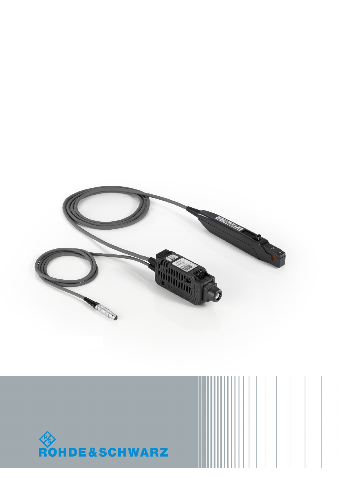
RT-ZC30
Current Probe
User Manual
(>9ÜÖ2)
1409.7872.02 ─ 02
User Manual
Test & Measurement
Page 2

This manual describes the following R&S products:
●
R&S®RT-ZC30, Current Probe (1409.7772.02)
●
R&S®RT-ZA13, Probe Power Supply (1409.7789.02)
© 2017 Rohde & Schwarz GmbH & Co. KG
Mühldorfstr. 15, 81671 München, Germany
Phone: +49 89 41 29 - 0
Fax: +49 89 41 29 12 164
Email: [email protected]
Internet: www.rohde-schwarz.com
Subject to change – Data without tolerance limits is not binding.
R&S® is a registered trademark of Rohde & Schwarz GmbH & Co. KG.
Trade names are trademarks of their owners.
The following abbreviations are used in this manual: R&S®RT-ZC30 is abbreviated as R&S RT-ZC30.
Page 3
Basic Safety Instructions
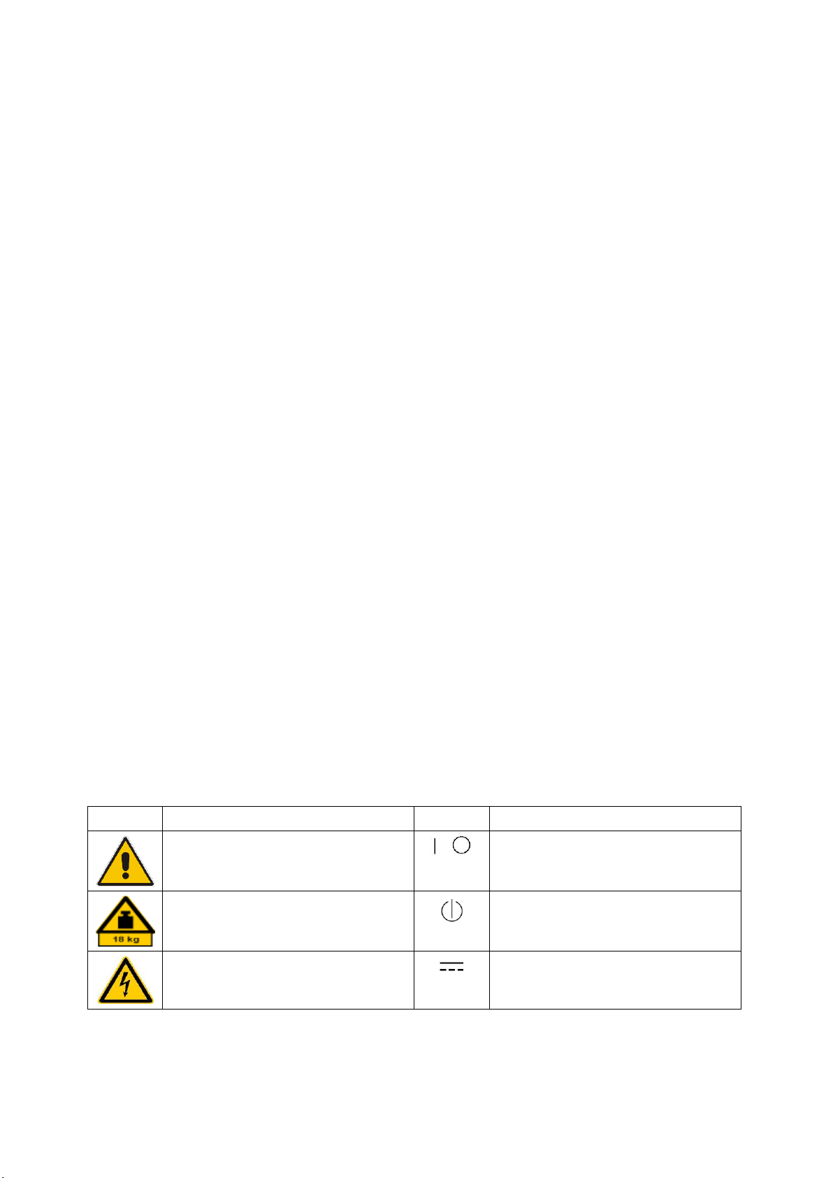
Symbol
Meaning
Symbol
Meaning
Notice, general danger location
Observe product documentation
ON/OFF Power
Caution when handling heavy equipment
Standby indication
Danger of electric shock
Direct current (DC)
Always read through and comply with the following safety instructions!
All plants and locations of the Rohde & Schwarz group of companies make every effort to keep the safety
standards of our products up to date and to offer our customers the highest possible degree of safety. Our
products and the auxiliary equipment they require are designed, built and tested in accordance with the
safety standards that apply in each case. Compliance with these standards is continuously monitored by
our quality assurance system. The product described here has been designed, built and tested in
accordance with the EC Certificate of Conformity and has left the manufacturer’s plant in a condition fully
complying with safety standards. To maintain this condition and to ensure safe operation, you must
observe all instructions and warnings provided in this manual. If you have any questions regarding these
safety instructions, the Rohde & Schwarz group of companies will be happy to answer them.
Furthermore, it is your responsibility to use the product in an appropriate manner. This product is designed
for use solely in industrial and laboratory environments or, if expressly permitted, also in the field and must
not be used in any way that may cause personal injury or property damage. You are responsible if the
product is used for any purpose other than its designated purpose or in disregard of the manufacturer's
instructions. The manufacturer shall assume no responsibility for such use of the product.
The product is used for its designated purpose if it is used in accordance with its product documentation
and within its performance limits (see data sheet, documentation, the following safety instructions). Using
the product requires technical skills and, in some cases, a basic knowledge of English. It is therefore
essential that only skilled and specialized staff or thoroughly trained personnel with the required skills be
allowed to use the product. If personal safety gear is required for using Rohde & Schwarz products, this
will be indicated at the appropriate place in the product documentation. Keep the basic safety instructions
and the product documentation in a safe place and pass them on to the subsequent users.
Observing the safety instructions will help prevent personal injury or damage of any kind caused by
dangerous situations. Therefore, carefully read through and adhere to the following safety instructions
before and when using the product. It is also absolutely essential to observe the additional safety
instructions on personal safety, for example, that appear in relevant parts of the product documentation. In
these safety instructions, the word "product" refers to all merchandise sold and distributed by the Rohde &
Schwarz group of companies, including instruments, systems and all accessories. For product-specific
information, see the data sheet and the product documentation.
Safety labels on products
The following safety labels are used on products to warn against risks and dangers.
1171.0000.42 - 09 Page 1
Page 4
Basic Safety Instructions
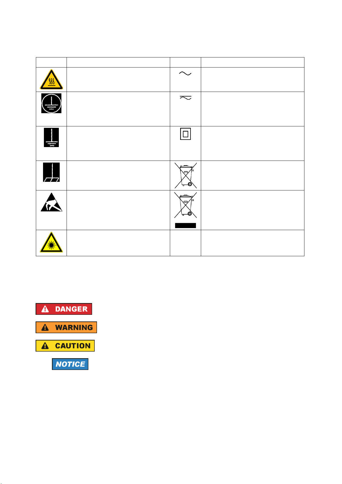
Symbol
Meaning
Symbol
Meaning
Caution ! Hot surface
Alternating current (AC)
Protective conductor terminal
To identify any terminal which is intended for
connection to an external conductor for
protection against electric shock in case of a
fault, or the terminal of a protective earth
Direct/alternating current (DC/AC)
Earth (Ground)
Class II Equipment
to identify equipment meeting the safety
requirements specified for Class II equipment
(device protected by double or reinforced
insulation)
Frame or chassis Ground terminal
EU labeling for batteries and accumulators
For additional information, see section "Waste
disposal/Environmental protection", item 1.
Be careful when handling electrostatic sensitive
devices
EU labeling for separate collection of electrical
and electronic devices
For additional information, see section "Waste
disposal/Environmental protection", item 2.
Warning! Laser radiation
For additional information, see section
"Operation", item 7.
Indicates a hazardous situation which, if not avoided, will result in death or
serious injury.
Indicates a hazardous situation which, if not avoided, could result in death or
serious injury.
Indicates a hazardous situation which, if not avoided, could result in minor or
moderate injury.
Indicates information considered important, but not hazard-related, e.g.
messages relating to property damage.
In the product documentation, the word ATTENTION is used synonymously.
Signal words and their meaning
The following signal words are used in the product documentation in order to warn the reader about risks
and dangers.
These signal words are in accordance with the standard definition for civil applications in the European
Economic Area. Definitions that deviate from the standard definition may also exist in other economic
areas or military applications. It is therefore essential to make sure that the signal words described here
are always used only in connection with the related product documentation and the related product. The
use of signal words in connection with unrelated products or documentation can result in misinterpretation
and in personal injury or material damage.
1171.0000.42 - 09 Page 2
Page 5

Basic Safety Instructions
Operating states and operating positions
The product may be operated only under the operating conditions and in the positions specified by the
manufacturer, without the product's ventilation being obstructed. If the manufacturer's specifications are
not observed, this can result in electric shock, fire and/or serious personal injury or death. Applicable local
or national safety regulations and rules for the prevention of accidents must be observed in all work
performed.
1. Unless otherwise specified, the following requirements apply to Rohde & Schwarz products:
predefined operating position is always with the housing floor facing down, IP protection 2X, use only
indoors, max. operating altitude 2000 m above sea level, max. transport altitude 4500 m above sea
level. A tolerance of ±10 % shall apply to the nominal voltage and ±5 % to the nominal frequency,
overvoltage category 2, pollution degree 2.
2. Do not place the product on surfaces, vehicles, cabinets or tables that for reasons of weight or stability
are unsuitable for this purpose. Always follow the manufacturer's installation instructions when
installing the product and fastening it to objects or structures (e.g. walls and shelves). An installation
that is not carried out as described in the product documentation could result in personal injury or
even death.
3. Do not place the product on heat-generating devices such as radiators or fan heaters. The ambient
temperature must not exceed the maximum temperature specified in the product documentation or in
the data sheet. Product overheating can cause electric shock, fire and/or serious personal injury or
even death.
Electrical safety
If the information on electrical safety is not observed either at all or to the extent necessary, electric shock,
fire and/or serious personal injury or death may occur.
1. Prior to switching on the product, always ensure that the nominal voltage setting on the product
matches the nominal voltage of the mains-supply network. If a different voltage is to be set, the power
fuse of the product may have to be changed accordingly.
2. In the case of products of safety class I with movable power cord and connector, operation is
permitted only on sockets with a protective conductor contact and protective conductor.
3. Intentionally breaking the protective conductor either in the feed line or in the product itself is not
permitted. Doing so can result in the danger of an electric shock from the product. If extension cords
or connector strips are implemented, they must be checked on a regular basis to ensure that they are
safe to use.
4. If there is no power switch for disconnecting the product from the mains, or if the power switch is not
suitable for this purpose, use the plug of the connecting cable to disconnect the product from the
mains. In such cases, always ensure that the power plug is easily reachable and accessible at all
times. For example, if the power plug is the disconnecting device, the length of the connecting cable
must not exceed 3 m. Functional or electronic switches are not suitable for providing disconnection
from the AC supply network. If products without power switches are integrated into racks or systems,
the disconnecting device must be provided at the system level.
5. Never use the product if the power cable is damaged. Check the power cables on a regular basis to
ensure that they are in proper operating condition. By taking appropriate safety measures and
carefully laying the power cable, ensure that the cable cannot be damaged and that no one can be
hurt by, for example, tripping over the cable or suffering an electric shock.
1171.0000.42 - 09 Page 3
Page 6

Basic Safety Instructions
6. The product may be operated only from TN/TT supply networks fuse-protected with max. 16 A (higher
fuse only after consulting with the Rohde & Schwarz group of companies).
7. Do not insert the plug into sockets that are dusty or dirty. Insert the plug firmly and all the way into the
socket provided for this purpose. Otherwise, sparks that result in fire and/or injuries may occur.
8. Do not overload any sockets, extension cords or connector strips; doing so can cause fire or electric
shocks.
9. For measurements in circuits with voltages V
> 30 V, suitable measures (e.g. appropriate
rms
measuring equipment, fuse protection, current limiting, electrical separation, insulation) should be
taken to avoid any hazards.
10. Ensure that the connections with information technology equipment, e.g. PCs or other industrial
computers, comply with the IEC 60950-1 / EN 60950-1 or IEC 61010-1 / EN 61010-1 standards that
apply in each case.
11. Unless expressly permitted, never remove the cover or any part of the housing while the product is in
operation. Doing so will expose circuits and components and can lead to injuries, fire or damage to the
product.
12. If a product is to be permanently installed, the connection between the protective conductor terminal
on site and the product's protective conductor must be made first before any other connection is
made. The product may be installed and connected only by a licensed electrician.
13. For permanently installed equipment without built-in fuses, circuit breakers or similar protective
devices, the supply circuit must be fuse-protected in such a way that anyone who has access to the
product, as well as the product itself, is adequately protected from injury or damage.
14. Use suitable overvoltage protection to ensure that no overvoltage (such as that caused by a bolt of
lightning) can reach the product. Otherwise, the person operating the product will be exposed to the
danger of an electric shock.
15. Any object that is not designed to be placed in the openings of the housing must not be used for this
purpose. Doing so can cause short circuits inside the product and/or electric shocks, fire or injuries.
16. Unless specified otherwise, products are not liquid-proof (see also section "Operating states and
operating positions", item 1). Therefore, the equipment must be protected against penetration by
liquids. If the necessary precautions are not taken, the user may suffer electric shock or the product
itself may be damaged, which can also lead to personal injury.
17. Never use the product under conditions in which condensation has formed or can form in or on the
product, e.g. if the product has been moved from a cold to a warm environment. Penetration by water
increases the risk of electric shock.
18. Prior to cleaning the product, disconnect it completely from the power supply (e.g. AC supply network
or battery). Use a soft, non-linting cloth to clean the product. Never use chemical cleaning agents such
as alcohol, acetone or diluents for cellulose lacquers.
Operation
1. Operating the products requires special training and intense concentration. Make sure that persons
who use the products are physically, mentally and emotionally fit enough to do so; otherwise, injuries
or material damage may occur. It is the responsibility of the employer/operator to select suitable
personnel for operating the products.
1171.0000.42 - 09 Page 4
Page 7

Basic Safety Instructions
2. Before you move or transport the product, read and observe the section titled "Transport".
3. As with all industrially manufactured goods, the use of substances that induce an allergic reaction
(allergens) such as nickel cannot be generally excluded. If you develop an allergic reaction (such as a
skin rash, frequent sneezing, red eyes or respiratory difficulties) when using a Rohde & Schwarz
product, consult a physician immediately to determine the cause and to prevent health problems or
stress.
4. Before you start processing the product mechanically and/or thermally, or before you take it apart, be
sure to read and pay special attention to the section titled "Waste disposal/Environmental protection",
item 1.
5. Depending on the function, certain products such as RF radio equipment can produce an elevated
level of electromagnetic radiation. Considering that unborn babies require increased protection,
pregnant women must be protected by appropriate measures. Persons with pacemakers may also be
exposed to risks from electromagnetic radiation. The employer/operator must evaluate workplaces
where there is a special risk of exposure to radiation and, if necessary, take measures to avert the
potential danger.
6. Should a fire occur, the product may release hazardous substances (gases, fluids, etc.) that can
cause health problems. Therefore, suitable measures must be taken, e.g. protective masks and
protective clothing must be worn.
7. Laser products are given warning labels that are standardized according to their laser class. Lasers
can cause biological harm due to the properties of their radiation and due to their extremely
concentrated electromagnetic power. If a laser product (e.g. a CD/DVD drive) is integrated into a
Rohde & Schwarz product, absolutely no other settings or functions may be used as described in the
product documentation. The objective is to prevent personal injury (e.g. due to laser beams).
8. EMC classes (in line with EN 55011/CISPR 11, and analogously with EN 55022/CISPR 22,
EN 55032/CISPR 32)
Class A equipment:
Equipment suitable for use in all environments except residential environments and environments
that are directly connected to a low-voltage supply network that supplies residential buildings
Note: Class A equipment is intended for use in an industrial environment. This equipment may
cause radio disturbances in residential environments, due to possible conducted as well as
radiated disturbances. In this case, the operator may be required to take appropriate measures to
eliminate these disturbances.
Class B equipment:
Equipment suitable for use in residential environments and environments that are directly
connected to a low-voltage supply network that supplies residential buildings
Repair and service
1. The product may be opened only by authorized, specially trained personnel. Before any work is
performed on the product or before the product is opened, it must be disconnected from the AC supply
network. Otherwise, personnel will be exposed to the risk of an electric shock.
1171.0000.42 - 09 Page 5
Page 8

Basic Safety Instructions
2. Adjustments, replacement of parts, maintenance and repair may be performed only by electrical
experts authorized by Rohde & Schwarz. Only original parts may be used for replacing parts relevant
to safety (e.g. power switches, power transformers, fuses). A safety test must always be performed
after parts relevant to safety have been replaced (visual inspection, protective conductor test,
insulation resistance measurement, leakage current measurement, functional test). This helps ensure
the continued safety of the product.
Batteries and rechargeable batteries/cells
If the information regarding batteries and rechargeable batteries/cells is not observed either at all or to the
extent necessary, product users may be exposed to the risk of explosions, fire and/or serious personal
injury, and, in some cases, death. Batteries and rechargeable batteries with alkaline electrolytes (e.g.
lithium cells) must be handled in accordance with the EN 62133 standard.
1. Cells must not be taken apart or crushed.
2. Cells or batteries must not be exposed to heat or fire. Storage in direct sunlight must be avoided.
Keep cells and batteries clean and dry. Clean soiled connectors using a dry, clean cloth.
3. Cells or batteries must not be short-circuited. Cells or batteries must not be stored in a box or in a
drawer where they can short-circuit each other, or where they can be short-circuited by other
conductive materials. Cells and batteries must not be removed from their original packaging until they
are ready to be used.
4. Cells and batteries must not be exposed to any mechanical shocks that are stronger than permitted.
5. If a cell develops a leak, the fluid must not be allowed to come into contact with the skin or eyes. If
contact occurs, wash the affected area with plenty of water and seek medical aid.
6. Improperly replacing or charging cells or batteries that contain alkaline electrolytes (e.g. lithium cells)
can cause explosions. Replace cells or batteries only with the matching Rohde & Schwarz type (see
parts list) in order to ensure the safety of the product.
7. Cells and batteries must be recycled and kept separate from residual waste. Rechargeable batteries
and normal batteries that contain lead, mercury or cadmium are hazardous waste. Observe the
national regulations regarding waste disposal and recycling.
8. Follow the transport stipulations of the carrier (IATA-DGR, IMDG-Code, ADR, RID) when returning
lithium batteries to Rohde & Schwarz subsidiaries.
Transport
1. The product may be very heavy. Therefore, the product must be handled with care. In some cases,
the user may require a suitable means of lifting or moving the product (e.g. with a lift-truck) to avoid
back or other physical injuries.
2. Handles on the products are designed exclusively to enable personnel to transport the product. It is
therefore not permissible to use handles to fasten the product to or on transport equipment such as
cranes, fork lifts, wagons, etc. The user is responsible for securely fastening the products to or on the
means of transport or lifting. Observe the safety regulations of the manufacturer of the means of
transport or lifting. Noncompliance can result in personal injury or material damage.
1171.0000.42 - 09 Page 6
Page 9

Instrucciones de seguridad elementales
3. If you use the product in a vehicle, it is the sole responsibility of the driver to drive the vehicle safely
and properly. The manufacturer assumes no responsibility for accidents or collisions. Never use the
product in a moving vehicle if doing so could distract the driver of the vehicle. Adequately secure the
product in the vehicle to prevent injuries or other damage in the event of an accident.
Waste disposal/Environmental protection
1. Specially marked equipment has a battery or accumulator that must not be disposed of with unsorted
municipal waste, but must be collected separately. It may only be disposed of at a suitable collection
point or via a Rohde & Schwarz customer service center.
2. Waste electrical and electronic equipment must not be disposed of with unsorted municipal waste, but
must be collected separately.
Rohde & Schwarz GmbH & Co. KG has developed a disposal concept and takes full responsibility for
take-back obligations and disposal obligations for manufacturers within the EU. Contact your
Rohde & Schwarz customer service center for environmentally responsible disposal of the product.
3. If products or their components are mechanically and/or thermally processed in a manner that goes
beyond their intended use, hazardous substances (heavy-metal dust such as lead, beryllium, nickel)
may be released. For this reason, the product may only be disassembled by specially trained
personnel. Improper disassembly may be hazardous to your health. National waste disposal
regulations must be observed.
4. If handling the product releases hazardous substances or fuels that must be disposed of in a special
way, e.g. coolants or engine oils that must be replenished regularly, the safety instructions of the
manufacturer of the hazardous substances or fuels and the applicable regional waste disposal
regulations must be observed. Also observe the relevant safety instructions in the product
documentation. The improper disposal of hazardous substances or fuels can cause health problems
and lead to environmental damage.
For additional information about environmental protection, visit the Rohde & Schwarz website.
1171.0000.42 - 09 Page 7
Page 10
Instructions - Instrucciones
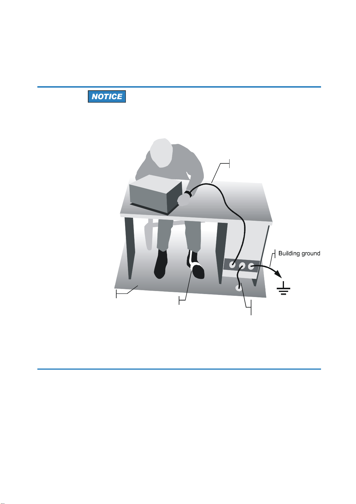
Wrist strap with cord
Ground connection
of operational site
Heel strap
Instructions for Electrostatic Discharge Protection
Risk of damaging electronic components
To avoid damage of electronic components, the operational site must be
protected against electrostatic discharge (ESD).
Floor mat
The following two methods of ESD protection may be used together or
separately:
, Wrist strap with cord to ground connection
, Conductive floor mat and heel strap combination
1171.0300.62 E/Esp-3
Page 11

Customer Support
Technical support – where and when you need it
For quick, expert help with any Rohde & Schwarz equipment, contact one of our Customer Support
Centers. A team of highly qualified engineers provides telephone support and will work with you to find a
solution to your query on any aspect of the operation, programming or applications of Rohde & Schwarz
equipment.
Up-to-date information and upgrades
To keep your instrument up-to-date and to be informed about new application notes related to your
instrument, please send an e-mail to the Customer Support Center stating your instrument and your wish.
We will take care that you will get the right information.
Europe, Africa, Middle East
North America
Latin America
Asia/Pacific
China
Phone +49 89 4129 12345
Phone 1-888-TEST-RSA (1-888-837-8772)
Phone +1-410-910-7988
Phone +65 65 13 04 88
Phone +86-800-810-8228 /
+86-400-650-5896
1171.0200.22-06.00
Page 12

R&S®RT-ZC30
Contents
Contents
1 Notes on Safety......................................................................5
2 Product Description............................................................ 10
2.1 Product Overview............................................................................... 10
2.2 Key Features....................................................................................... 10
2.3 Inspecting the Contents..................................................................... 10
2.4 Description of the Probe.................................................................... 11
2.4.1 Probe Overview.................................................................................... 11
2.4.2 Terminator.............................................................................................12
2.4.3 Sensor...................................................................................................13
2.4.4 Key and LEDs....................................................................................... 14
3 Measuring Procedure.......................................................... 16
3.1 Preparing the Measurement...............................................................16
3.2 Demagnetizing and Zero Adjustment............................................... 19
3.3 Connecting the Probe to the DUT..................................................... 20
3.4 Disconnecting the Probe from the DUT............................................25
3.5 Troubleshooting..................................................................................26
4 Maintenance and Service....................................................28
4.1 Service Strategy..................................................................................28
4.2 Returning the Probe for Servicing.................................................... 28
4.3 Cleaning...............................................................................................29
4.4 Calibration Interval............................................................................. 29
4.5 Discarding the Probe..........................................................................29
5 R&S RT-ZA13 Probe Power Supply................................... 30
3User Manual 1409.7872.02 ─ 02
Page 13

R&S®RT-ZC30
Contents
4User Manual 1409.7872.02 ─ 02
Page 14
R&S®RT-ZC30
Notes on Safety
1 Notes on Safety
Thank you for purchasing the R&S RT-ZC30 current probe.
To obtain maximum performance from the device, please read this manual first,
and keep it handy for future reference.
Risk of physical injury
This device is designed to comply with IEC 61010 Safety Standards, and
has been thoroughly tested for safety before shipment. However, mishandling during use could result in injury or death, and damage the device. Be
certain that you understand the instructions and precautions in the manual
before use.
Follow these precautions to ensure safe operation and to obtain the full benefits
of the various functions.
5User Manual 1409.7872.02 ─ 02
Page 15
R&S®RT-ZC30
Risk of fatal injury
●
To avoid electric shock, do not remove the device's cover. The internal
components of the device carry high voltages and may become very hot
during operation.
●
To avoid electric shock and short circuits, never attach the clamp to
bare, unisolated conductors.
Make sure to measure at a location on an insulated wire where the insulation is sufficient for the circuit voltage.
●
Be careful to avoid damaging the insulation surface while taking measurements.
Notes on Safety
●
Refer to the derating characteristics when measuring current that
includes a high-frequency component and never measure any current
that exceeds the rated current. Use with high frequencies or strong
magnetic fields may cause the device to become abnormally hot, resulting in fire, equipment damage, or burns.
●
To prevent fire or damage of the measurement target and device as well
as burns, exercise caution concerning the following when measuring
high-frequency currents or currents that contain high-frequency components:
– Eddy current loss may cause heating of the sensor head.
– Dielectric heating may cause heating of cord insulation and other
materials.
●
Connect the probe only to the secondary side of a breaker, so the
breaker can prevent an accident if a short circuit occurs. Never connect
it to the primary side of a breaker, because unrestricted current flow
could cause a serious accident if a short circuit occurs.
●
Be sure to observe all operating precautions for the oscilloscope and
other instruments to which this device is connected.
6User Manual 1409.7872.02 ─ 02
Page 16
R&S®RT-ZC30
Risk of fatal injury
●
This device is made for use with the R&S RT-ZA13 probe power supply.
●
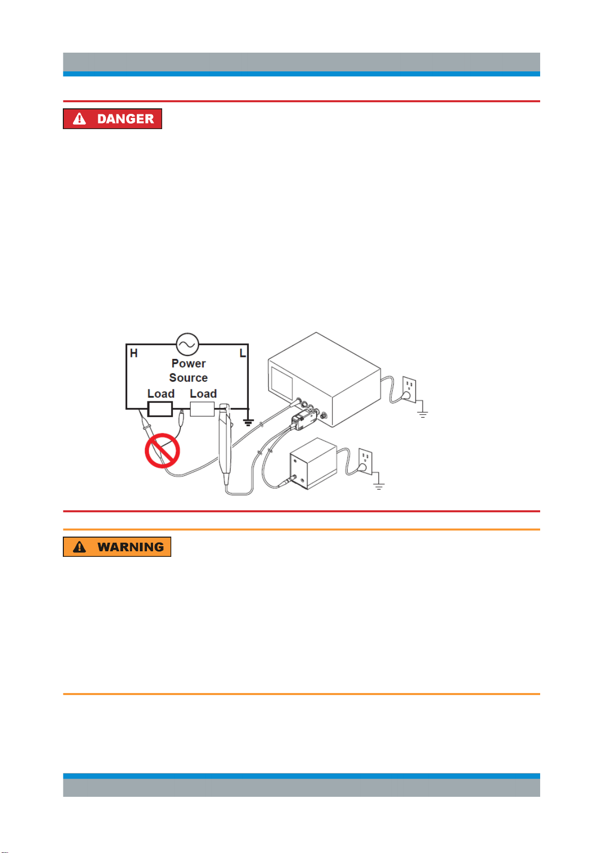
When using a measurement instrument that does not provide isolation
between its input terminals and chassis or other input terminals, please
pay attention to the following points. If a signal is applied to an input terminal other than that to which this device is connected, do not connect
the ground-side terminal to any nonground potential. Otherwise, shortcircuit current flows through the R&S RT-ZA13 probe power supply, or
this device from the ground terminal, which could cause an electrical
accident or damage.
Notes on Safety
Shock hazard
To avoid shock and short circuits, turn off all power before connecting the
device.
Do not allow the device to get wet, and do not take measurements with wet
hands. This may cause an electric shock.
To avoid electric shock when measuring live lines, wear appropriate protective gear, such as insulated rubber gloves, boots, and a safety helmet.
7User Manual 1409.7872.02 ─ 02
Page 17

R&S®RT-ZC30
Risk of instrument damage
●
To avoid damage to the device, protect it from vibration or shock during
transport and handling, and be especially careful to avoid dropping.
●
To avoid damage to the device, do not place the device on an unstable
table or an inclined place. Dropping or knocking down the device can
cause injury or damage to the device.
●
Do not store or use the device where it could be exposed to direct sunlight, high temperature, humidity, or condensation. Under such conditions, the device may be damaged and insulation may deteriorate so
that it no longer meets its specifications.
●
Do not store or use the device near induction heating systems (such as
high-frequency induction heating systems and IH cooking equipment)
Notes on Safety
●
Before using the device the first time, verify that it operates normally to
ensure that no damage occurred during storage or shipping. If you find
any damage, contact your dealer or R&S representative.
●
This device is not designed to be entirely water- or dust-proof. To avoid
damage, do not use it in a wet or dusty environment.
●
The sensor head is a precision assembly including a molded component, a ferrite core, and a Hall effect element. It may be damaged if subjected to sudden changes in ambient temperature, or mechanical strain
or shock, and therefore great care should be exercised in handling it.
●
Do not apply a static electricity or other source of high voltage to the
sensor. Doing so may damage the internal Hall elements and circuitry of
the sensor.
●
The mating surfaces of the sensor head are precision, and should be
treated with care. If these surfaces are scratched, performance may be
impaired.
●
Do not place foreign objects between the mating faces of the sensor
head, insert foreign objects into the gaps of the sensor head, or touch
the mating faces. Doing so may worsen the performances of the sensor
or interfere with clamping action.
●
While the POWER LED is on, keep the core section of the sensor
closed, except when clamping it onto the conductor to be measured.
The mating surface of the core section can be scratched while it is open.
8User Manual 1409.7872.02 ─ 02
Page 18
R&S®RT-ZC30
●
Keep the sensor head closed when not in use, to avoid accumulating
dust or dirt on the mating core surfaces, which could interfere with
clamp performance.
●
Avoid stepping on or pinching the cable, which could damage the cable
insulation.
●
Keep the cable well away from heat sources, as bare conductors could
be exposed if the insulation melts.
●
Do not obstruct the ventilation holes on the sides and bottom of the terminator, as it could overheat and be damaged, or cause a fire.
Strong electromagnetic fields
Correct measurement may be impossible in the presence of strong magnetic fields, such as near transformers and high-current conductors, or in
the presence of strong electromagnetic fields such as near radio transmitters.
Notes on Safety
9User Manual 1409.7872.02 ─ 02
Page 19

R&S®RT-ZC30
Product Description
Inspecting the Contents
2 Product Description
2.1 Product Overview
The R&S RT-ZC30 is an AC/DC current probe. It allows the user to make current
measurements from DC to 120 MHz. By clamping on the conductor to be measured, the current waveform is captured easily without interrupting the electric circuit.
2.2 Key Features
●
The sensor head has a clamp design that makes it possible to easily observe
current waveforms while current continues to flow through the conductor being
measured.
●
LED warnings indicate overload and unlocked sensor head.
●
You can observe low-current waveforms at the high sensitivity of 1 V/A.
●
Broadband frequency characteristics DC to 120 MHz.
●
Demagnetization and automatic zero adjustment functions make it easy to get
ready for measurement.
2.3 Inspecting the Contents
●
Inspect the package for damage.
Keep a damaged package and the cushioning material until the contents have
been checked for completeness and the device has been tested.
If the packaging material shows any signs of stress, notify the carrier as well
as your Rohde & Schwarz service center. Keep the package and cushioning
material for inspection.
●
Inspect the probe.
If there is any damage or defect, or if the R&S RT-ZC30 current probe does
not operate properly, notify your Rohde & Schwarz service center.
●
Inspect the accessories.
10User Manual 1409.7872.02 ─ 02
Page 20
R&S®RT-ZC30
Product Description
Description of the Probe
If the contents are incomplete or damaged, notify your Rohde & Schwarz service center.
The following accessories are delivered with the probe:
– User manual
– Carrying case
– R&S RT-Zxx datasheet
– Calibration certificate
– Documentation of calibrated values
2.4 Description of the Probe
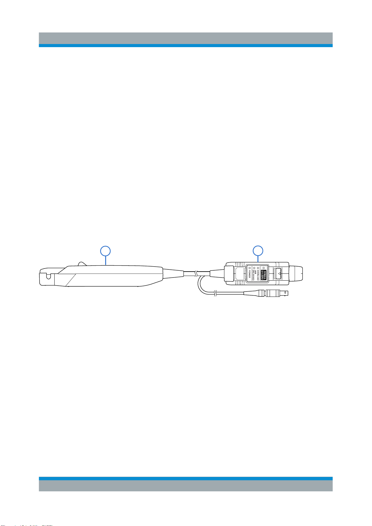
2.4.1 Probe Overview
Figure 2-1: Probe overview
1 = Sensor
2 = Terminator
1
2
11User Manual 1409.7872.02 ─ 02
Page 21
R&S®RT-ZC30
Product Description
Description of the Probe
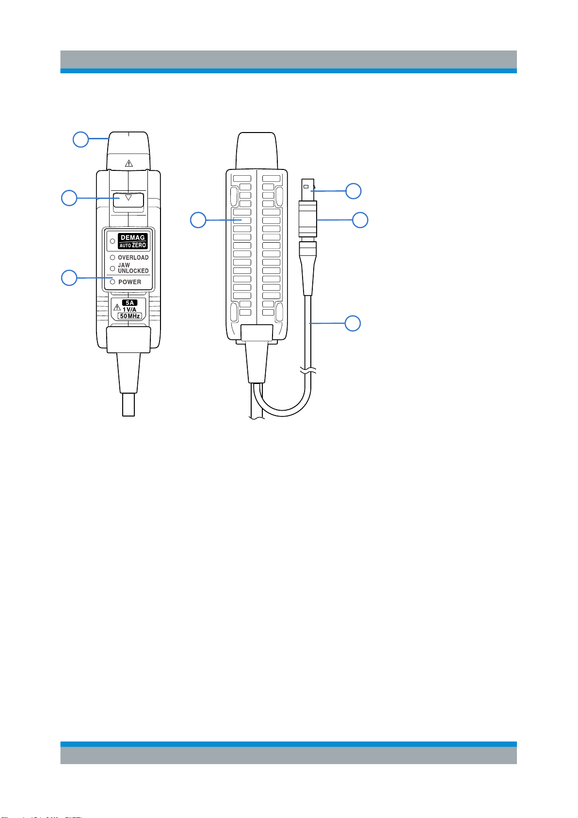
2.4.2 Terminator
1
2
3
5
44 6
7
Figure 2-2: Terminator overview
1 = Output connector
2 = Unlock lever
3 = Key and LEDs
4 = Ventilation holes
5 = Power plug
6 = Shell
7 = Power supply cord
Output connector
Connect to the BNC input connector of the waveform measuring instrument.
The current waveform of the measured conductor is output at a constant rate
(1 V/A).
The terminator’s output connector can be connected when the locking pin on the
waveform measurement instrument’s BNC input connector is in either the horizontal or vertical orientation.
Unlock Lever
The lock mechanism keeps the clamp closed.
12User Manual 1409.7872.02 ─ 02
Page 22
R&S®RT-ZC30
Product Description
Description of the Probe
Power plug
Connect the plug to the R&S RT-ZA13 probe power supply receptacle to supply
power to the sensor.
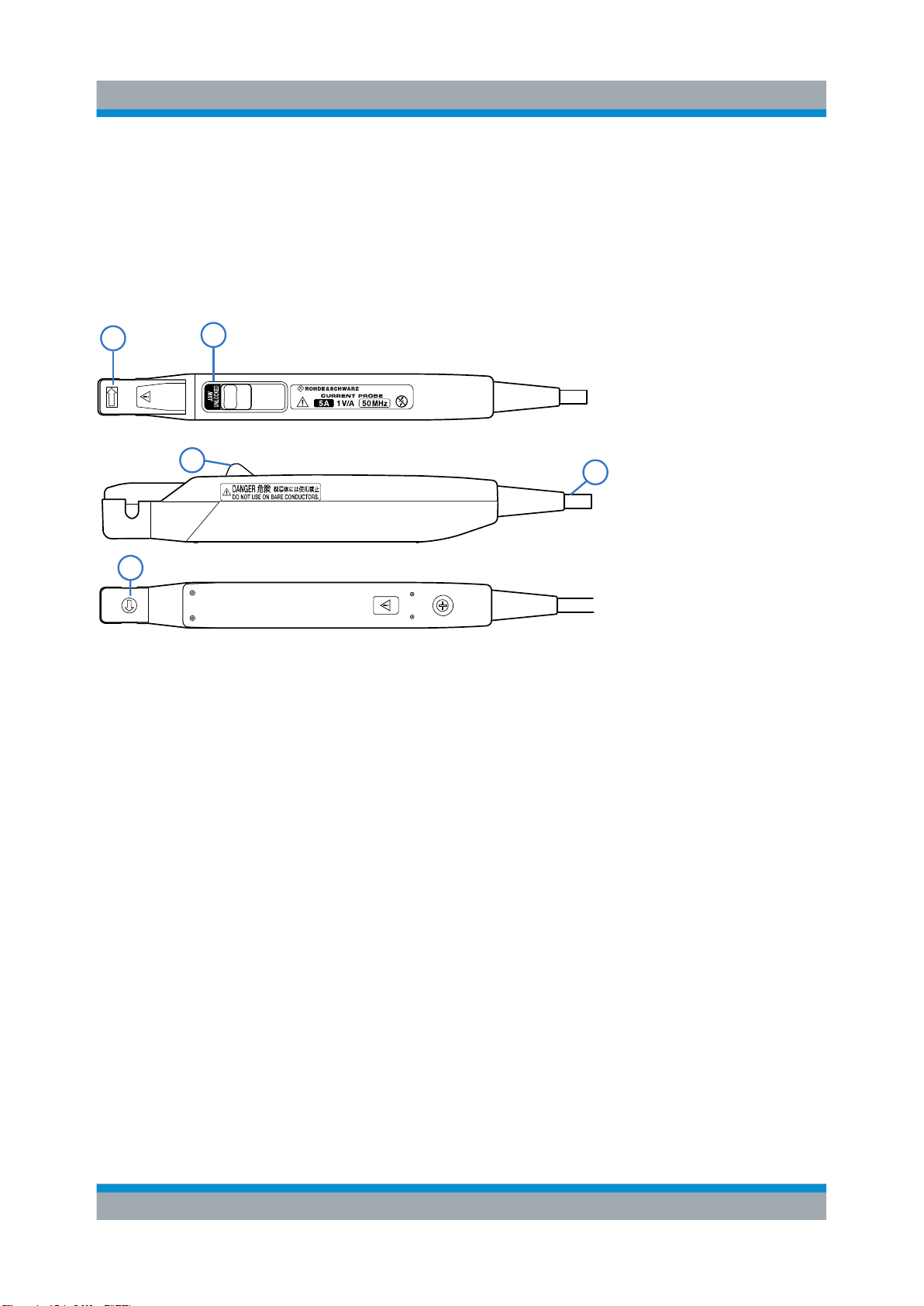
2.4.3 Sensor
1
1
Figure 2-3: Sensor overview
1 = Current direction indication
2 = Jaw unlocked
3 = Opening lever
4 = Sensor cord
2
3
RT-ZC30
4
Current direction indication
Clamp the device to the conductor so that the direction in which the current being
measured is flowing matches the arrow.
Opening lever
Operating lever for opening the sensor head. Always use this lever to open the
sensor head.
JAW UNLOCKED indication
If the sensor head is unlocked you can see this indication on the probe.
Sensor head
The sensor head clamps on the conductor being measured, and carries out the
actual current measurement.
13User Manual 1409.7872.02 ─ 02
Page 23
R&S®RT-ZC30
Product Description
Description of the Probe
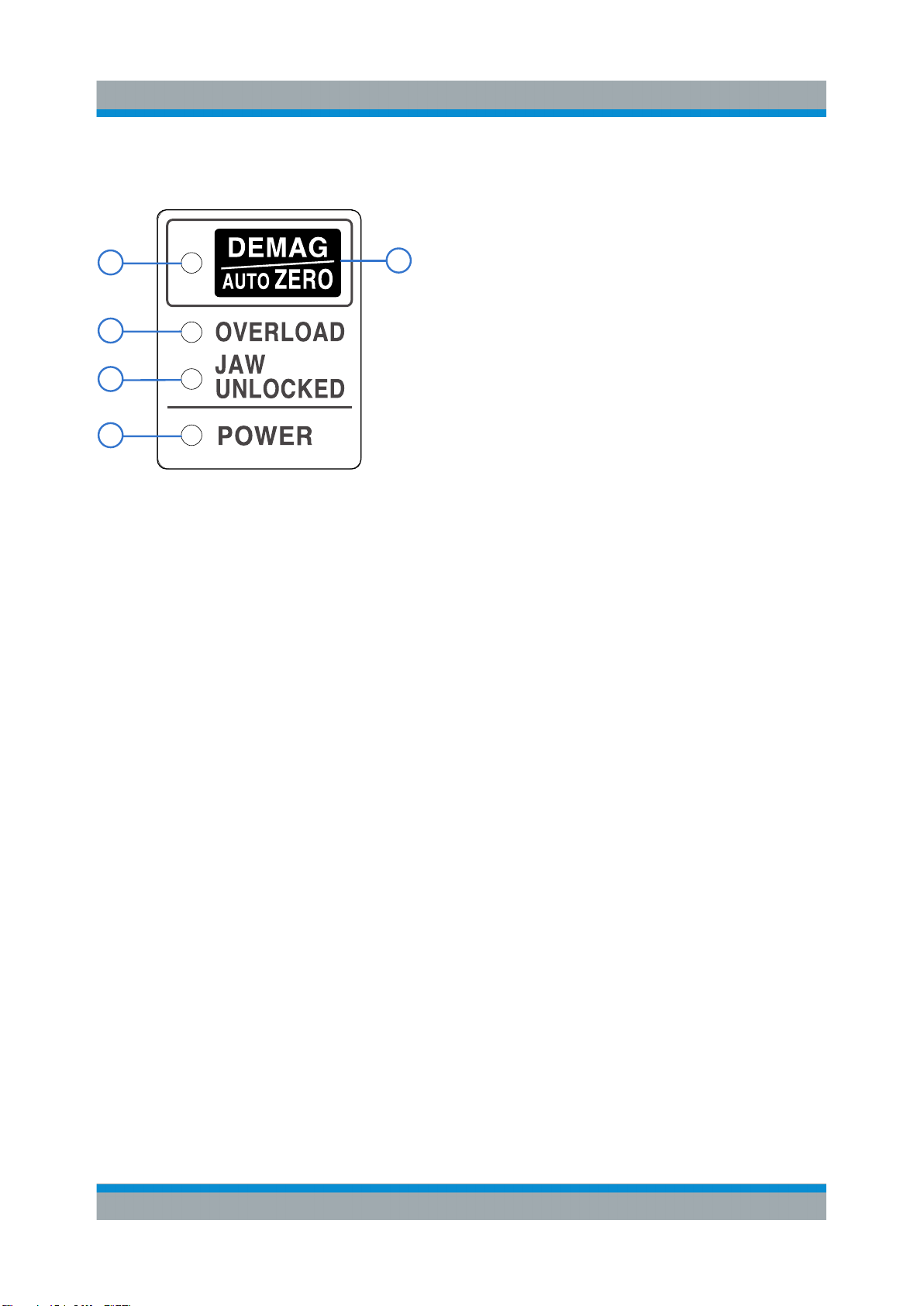
2.4.4 Key and LEDs
1
3
4
5
Figure 2-4: Key and LEDs
1 = DEMAG/AUTO ZERO LED
2 = DEMAG/AUTO ZERO Key
3 = OVERLOAD
4 = JAW UNLOCKED LED
5 = POWER LED
2
The key is used to perform demagnetization and zero adjustment, while the LEDs
indicate the device status.
DEMAG/AUTO ZERO key
Performs demagnetization and zero adjustment.
Press this key long (approx. 1 sec.) for demagnetization and zero adjustment.
Press this key short (within 0.5 sec.) for a zero adjustment only.
Demagnetization and zero adjustment cannot be be performed in the following
circumstances:
●
The sensor head is unlocked (JAW UNLOCKED LED is lit up)
●
During an overload condition (the OVERLOAD LED is flashing)
●
When a measured current is detected
DEMAG/AUTO ZERO LED
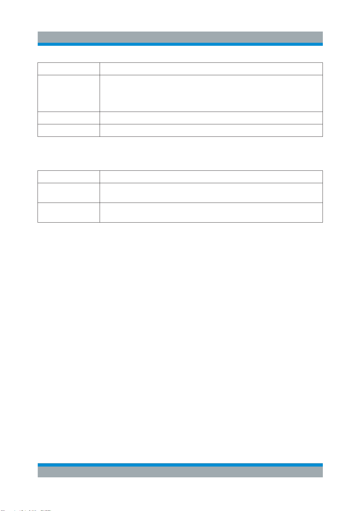
Shows the status of the demagnetazation/zeroing proccess. The following states
are defined:
14User Manual 1409.7872.02 ─ 02
Page 24
R&S®RT-ZC30
Color State
Product Description
Description of the Probe
Slow flashing
orange
Orange During demagnetization and zero adjustment process
Off After demagnetization and zero adjustment is successfully completed
●
Before demagnetization and zero adjustment (when either can be performed)
●
After an overload is detected
●
When demagnetization terminated abnormally
OVERLOAD LED
Shows the overload status of the system The following states are defined:
Color State
Slow flashing red Indicates that the maximum rated current is about to be reached. Exercise
care so as not to exceed the rating.
Fast flashing red Indicates that the maximum rated current is being exceeded. Remove the
sensor from the measurement target immediately.
JAW UNLOCKED LED
The JAW UNLOCKED LED turns red (lighting up continuously) if the sensor head
is not locked.
POWER LED
The POWER LED turns green (lighting up continuously) when the device is energized.
15User Manual 1409.7872.02 ─ 02
Page 25
R&S®RT-ZC30
Measuring Procedure
Preparing the Measurement
3 Measuring Procedure
3.1 Preparing the Measurement
Voltage check
When using a different power supply than the R&S RT-ZA13 probe power
supply, before turning on the power, make sure that the voltage of the used
power supply matches the supply voltage indicated in the data sheet "R&S
RT-Zxx Oscilloscope Probes".
●
The output of this device is terminated internally. Use a high impedance
input of the measuring instrument. With an input impedance of 50 Ω,
accurate measurement is not possible.
●
If using BNC-banana plug adapters or similar to connect to input terminals other than BNC connectors, make sure the polarity is correct.
●
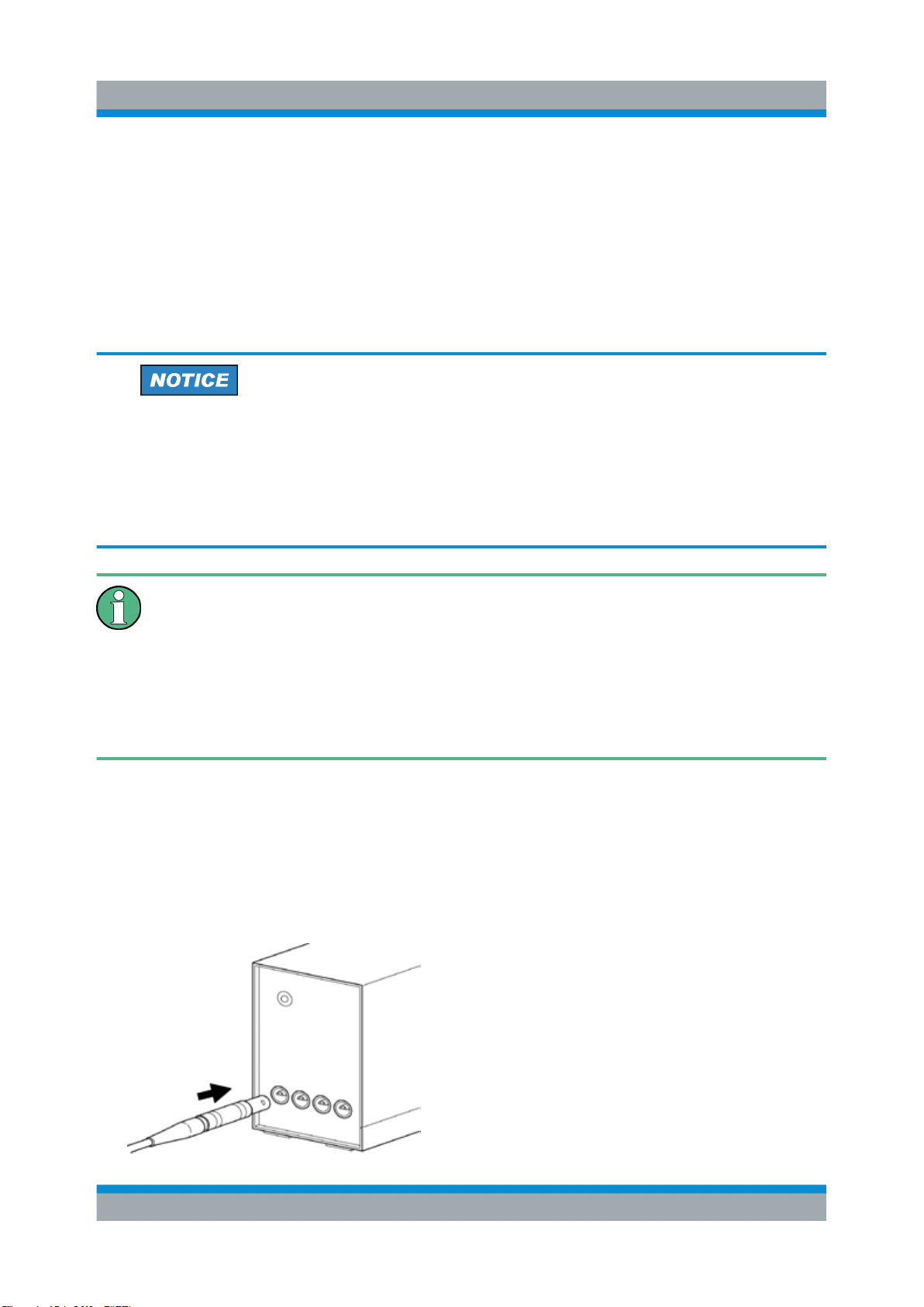
Turn the collar until it clicks, and check that it is locked securely.
1. Have the R&S RT-ZA13 probe power supply, and an oscilloscope or wave-
form measuring instrument ready.
2. Turn the power switch off and connect the power cord.
3. Connect the power plug of the R&S RT-ZC30 to the power receptacle of the
R&S RT-ZA13 probe power supply.
16User Manual 1409.7872.02 ─ 02
Page 26
R&S®RT-ZC30
Measuring Procedure
Preparing the Measurement
4. Check that the conductor being measured is not clamped when supplying
power to the R&S RT-ZC30. When power is turned on, a demagnetizing
waveform is initially applied to the output. This is intentional in the design, and
not a fault.
5. Turn the R&S RT-ZA13 probe power supply power switch on, and check that
the front panel power indicator lights.
The POWER LED lights up in green and the DEMAG/AUTO ZERO LED is
slowly flashing in orange.
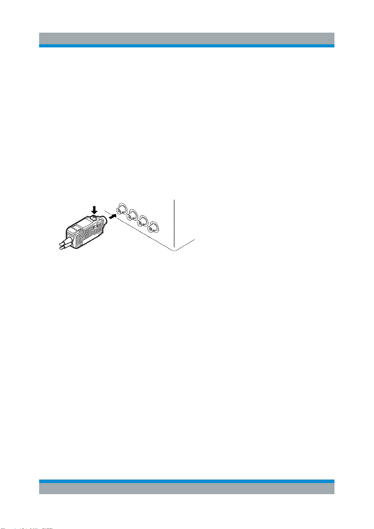
6. Connect the output connector of the R&S RT-ZC30 to one of the BNC input
connectors of the oscilloscope. Turn the collar until it clicks, and check that it
is locked securely.
Figure 3-1: Oscilloscope inputs
The current waveform of the measured conductor is output at a constant rate
(1 V/A).
7. Configure the probe connection at the oscilloscope. Make sure to set the fol-
lowing:
● Vertical unit = Ampere
● Coupling = DC
● Termination = 1 MΩ
● Manual Gain = 1 V/A
Alternatively, select "Predefined probe" = R&S RT-ZC30 if this selection is
available on the instrument.
The procedure depends on the used instrument and is described in the oscilloscope's user manual. Supported oscilloscopes are listed in the R&S RT-Zxx
data sheet.
8. When disconnecting the output connector, be sure to release the lock before
pulling off the connector. Forcibly pulling the connector without releasing the
lock, or pulling on the cable can damage the terminator.
17User Manual 1409.7872.02 ─ 02
Page 27
R&S®RT-ZC30
Risk of instrument damage
●
Check that the conductor being measured is not clamped when supplying power to the device. A demagnetizing waveform may be generated
when power is supplied, causing damage to components connected to
the circuit being measured.
●
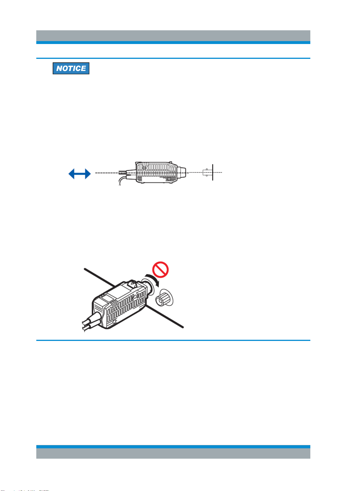
To avoid damaging the terminator, keep it oriented in a straight line relative to the waveform measurement instrument when connecting and disconnecting it.
●
To avoid damaging the output connector, pull the unlock lever toward
you and then pull the connector out and away from the waveform measurement instrument.
Measuring Procedure
Preparing the Measurement
●
To avoid damaging the output connector of the terminator, or the BNC
input terminal’s locking mechanism on the waveform measuring instrument, do not rotate when both terminals are connected. Ensure that
connections are not subject to stress.
18User Manual 1409.7872.02 ─ 02
Page 28
R&S®RT-ZC30
Measuring Procedure
Demagnetizing and Zero Adjustment
3.2 Demagnetizing and Zero Adjustment
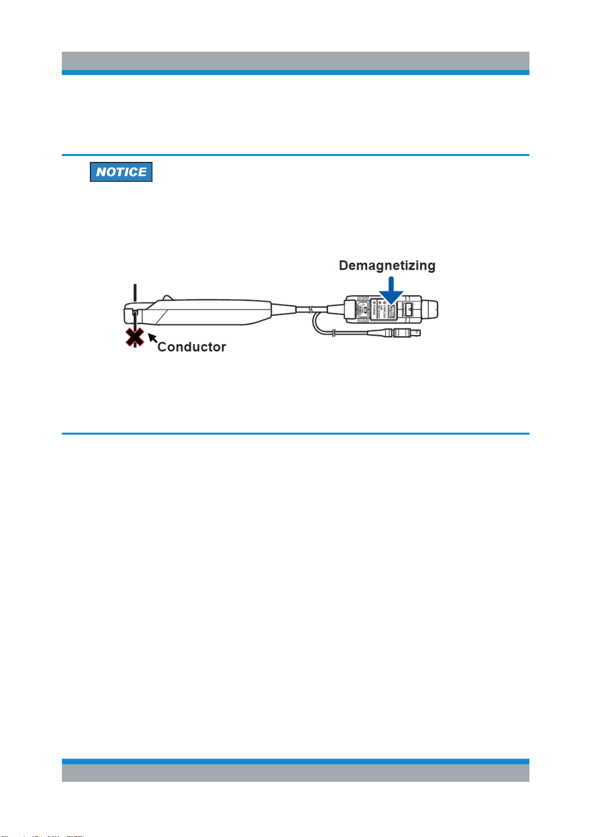
Risk of circuit damage
●
Do not demagnetize while the R&S RT-ZC30 is clamping a conductor to
be measured. Demagnetizing causes current to flow into the conductor,
which may damage parts in the circuit to be measured.
●
Check that the conductor being measured is not clamped when supplying power to the R&S RT-ZC30. When power is turned on, a demagnetizing waveform is initially applied to the output. This is intentional in the
design, and not a fault.
1. With the waveform measuring instrument input at ground, adjust the waveform
to the zero position.
2. Connect the R&S RT-ZC30 current probe and configure the oscilloscope as
described in Chapter 3.1, "Preparing the Measurement", on page 16.
3. Make sure that there is no conductor in the sensor aperture.
4. Press the opening lever until the JAW UNLOCK indication disappears, and
check that the sensor head is properly closed.
5. Press and hold the DEMAG/ AUTO ZERO key for about 1 second. Zero-
adjustment will be performed after demagnetization.
The process takes about 20 seconds. During demagnetizing, a demagnetizing
waveform is shown on the oscilloscope. The positive and negative components of this waveform may be asymmetrical.
Note: If the DEMAG/AUTO ZERO LED continues flashing instead of turning
off when the DEMAG/AUTO ZERO key is pressed, demagnetization and zero
adjustment did not complete normally.
19User Manual 1409.7872.02 ─ 02
Page 29
R&S®RT-ZC30
Measuring Procedure
Connecting the Probe to the DUT
Risk of instrument damage
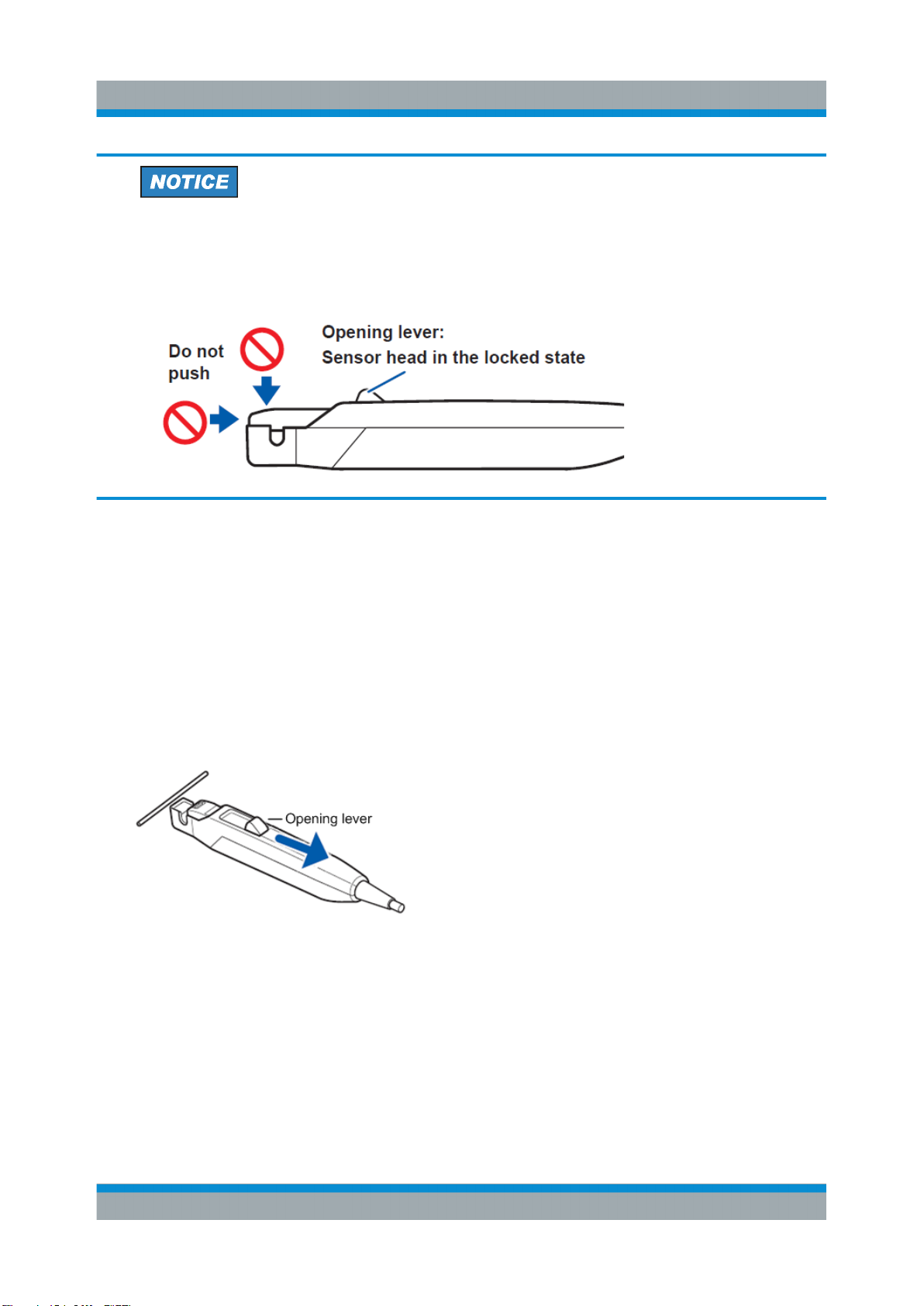
When opening the sensor head, always operate the opening lever. Subjecting the sensor head to force from the directions shown in the figure while it
is locked may damage the clamping mechanism.
3.3 Connecting the Probe to the DUT
1. Check that the system is safe, and that the preparations described in the pre-
ceding sections have been carried out.
2. Pull the sensor opening lever, so that the sensor head opens.
3. Align the sensor so that the current direction indication matches the direction
of current flow through the conductor to be measured. The conductor should
be in the center of the clamp aperture because the measurement may be
affected by the position within the clamp aperture of the conductor being measured.
4. Press the opening lever until the JAW UNLOCKED indication disappears, and
check that the sensor head is properly closed. The JAW UNLOCKED LED
turns off.
20User Manual 1409.7872.02 ─ 02
Page 30
R&S®RT-ZC30
Connecting the Probe to the DUT
If the sensor head is not properly closed, accurate measurement is not possible.
●
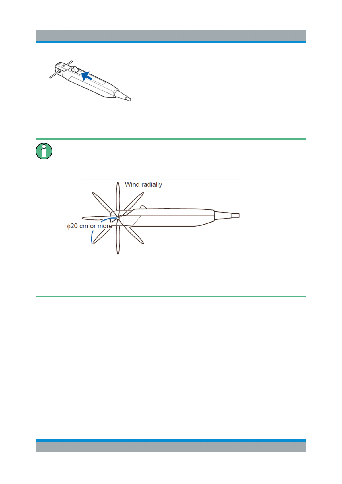
To measure DC or low-frequency current, multiple windings may be
used to increase relative sensitivity (10 windings multiplies the measured current by a factor of 10). However, in this case, the windings
should be made radially, with a diameter of at least 20 cm.
Measuring Procedure
●
Cord placement and the act of clamping the probe onto the conductor
being measured may trigger load fl uctuations, affecting the observed
waveform.
21User Manual 1409.7872.02 ─ 02
Page 31

R&S®RT-ZC30
Connecting the Probe to the DUT
Risk of instrument damage due to continuous input current
●
The maximum continuous input range is based on heat that is internally
generated during measurement. Always keep the input current below
this level. Exceeding the rated level may result in damage to the probe.
●
The maximum continuous input range varies according to the frequency
of the current being measured. Refer to the data sheet "R&S RT-Zxx
Oscilloscope Probes, Specifications"
●
The device may sustain damage from self-heating even at current levels
that are lower than the maximum rated current. The maximum rated current is a recommended value that assumes sine-wave input under standard conditions. Self-heating may happen if the ambient temperature
increases or the measurement current waveform contains other frequency components.
Measuring Procedure
●
If the input current exceeds a certain level, generated heat activates a
built-in safety function that blocks normal output. If this happens,
remove the input immediately (remove the sensor from the conductor
being measured, or reduce the input current to zero). Wait until the sensor has had sufficient time to cool before resuming operation.
●
Even if the input current does not exceed the rated continuous maximum current, continuous input for an extended period of time may result
in activation of the safety circuit to prevent damage resulting from heating of the sensor.
22User Manual 1409.7872.02 ─ 02
Page 32
R&S®RT-ZC30
Connecting the Probe to the DUT
Risk of instrument damage due to continuous input current
●
At high ambient temperatures, the built-in safety circuit may activate at
current input levels below the rated continuous maximum current.
●
Continuous input of current exceeding the rated maximum or repeated
activation of the safety function may result in damage to the device.
●
Current measurement exceeding approx. 1 kHz may result in temperature rise on the sensor-head. This is attributed to excitation loss that
cannot be prevented due to natural physical principles. Be careful to
avoid injury, electric shock due to short-circuits, or damage to the device
that may be caused by the increased temperature.
●
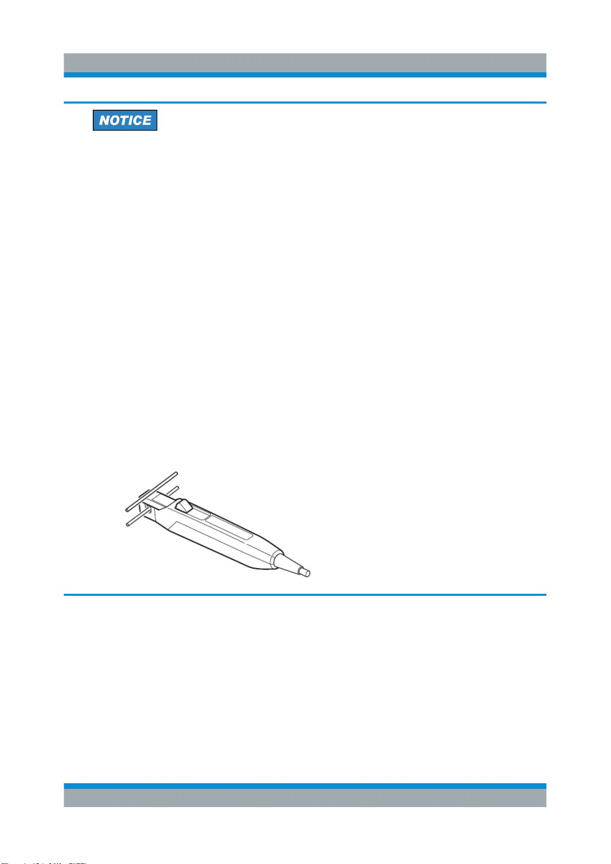
Do not place any unclamped conductor with an electric current of a frequency of 10 kHz or more near the sensor head. Current flowing in the
conductor nearby may heat up the sensor head and cause its temperature to rise, leading to damage to the sensor. For example, when one
side of a go-and-return conductor is clamped and the other side is also
placed near the sensor head as shown in the diagram, even if the electric current is lower than the consecutive maximum current, electric currents in both sides will heat up the sensor and raise the temperature,
thereby causing damage to the sensor.
Measuring Procedure
23User Manual 1409.7872.02 ─ 02
Page 33
R&S®RT-ZC30
●
Immediately after powering on, this device may be subject to an appreciable offset drift due to the effect of self-heating. To counteract this,
allow the device to warm up for about 30 minutes before carrying out
measurements.
●
When performing continuous measurements, it is necessary to be
aware that the offset voltage drifts, depending on factors such as the
ambient temperature.
●
Under certain circumstances, oscillation may occur while the power supply is on. This does not indicate a malfunction. Oscillation can be stopped and operation restored to normal by opening and closing the sensor
head.
●
Depending on the amplitude and frequency of the current being measured, the sensor head may emit a resonant sound. This sound may
also occur during demagnetizing operation, but it does not represent a
malfunction or device failure.
If foreign matter is adhered to the facing surfaces on the sensor head so
that a slight gap exists between the upper and lower sensors, the sensor head may also emit a resonant sound. Remove any foreign matter
using the cleaning method described in this manual.
An increase in the volume of the resonant sound during use may indicate that the gap between the upper and lower sensors has increased.
Since the sensor characteristics may change, it is recommended to calibrate the device.
Measuring Procedure
Connecting the Probe to the DUT
24User Manual 1409.7872.02 ─ 02
Page 34
R&S®RT-ZC30
Measuring Procedure
Disconnecting the Probe from the DUT
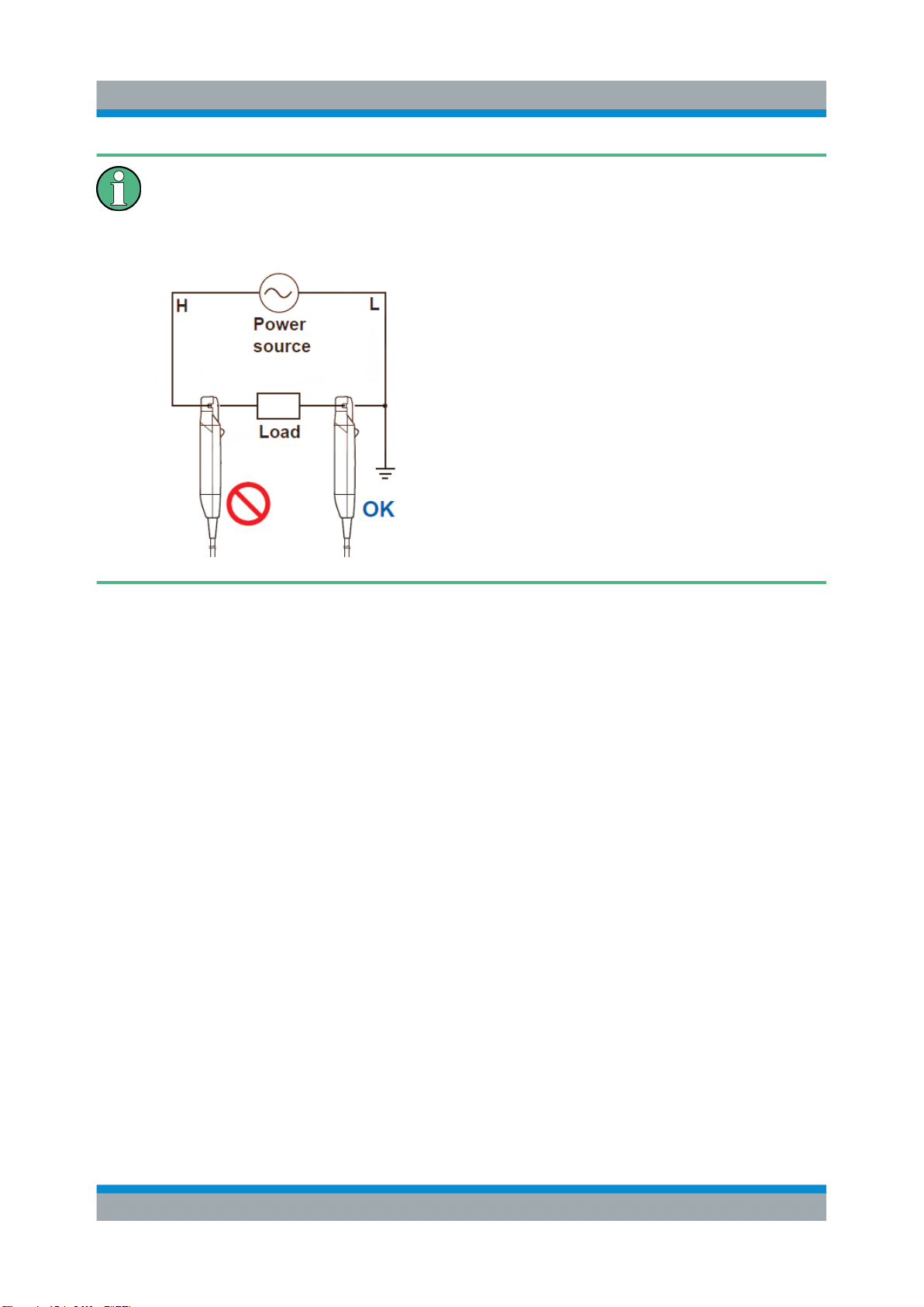
At high frequencies, common mode noise may affect measurements taken
on the high voltage side of circuits. If this occurs, reduce the frequency
range of the waveform measuring instrument, or clamp onto the low-voltage
side of the circuit, as appropriate.
3.4 Disconnecting the Probe from the DUT
Once measurement has completed:
1. Pull the opening lever toward you and remove the device from the conductor
being measured.
2. Disconnect the terminator from the waveform measurement instrument.
3. Turn the R&S RT-ZA13 probe power supply POWER switch off.
4. Remove the power plug of the device from the R&S RT-ZA13 probe power
supply.
5. Unplug the R&S RT-ZA13 probe power supply power cord from the electrical
outlet.
25User Manual 1409.7872.02 ─ 02
Page 35
R&S®RT-ZC30
Risk of instrument damage
●
To prevent wire breaks, do not pull on the cord to disconnect the output
connector from the waveform measurement instrument. Always grip the
terminator and pull the unlock lever toward you before disconnecting the
connector.
●
When disconnecting the device, grip the power supply plug’s shell and
do not pull on cords in order to prevent wiring breaks in the device’s
power cord or damage to R&S RT-ZA13 probe power supply.
Measuring Procedure
Troubleshooting
3.5 Troubleshooting
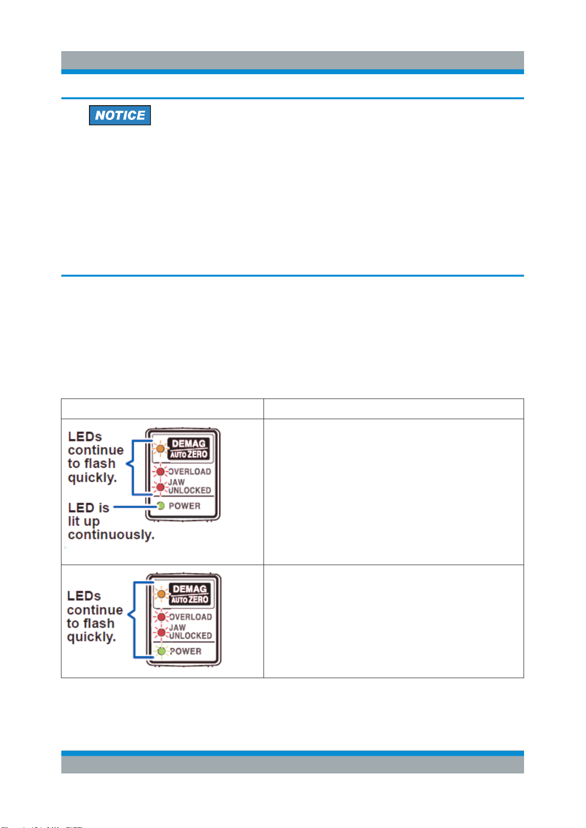
You can determine the nature of an error by observing the device’s LED. The following table explains possible error indications and their cause.
Error State Meaning
A temperature anomaly has been detected due to
heating caused by an overload.
Remove the device from the conductor being measured immediately. Allow the device to cool under
conditions of no input and then press the DEMAG/
AUTO ZERO key. The device returns to its state
when it was turned on.
Start measurement after performing demagnetization and zero adjustment again. It is recommended
to calibrate the device since internal components
may have been subject to stress.
An internal CPU malfunction (checksum error) has
occurred. Send it to the service center for repair.
26User Manual 1409.7872.02 ─ 02
Page 36
R&S®RT-ZC30
Error State Meaning
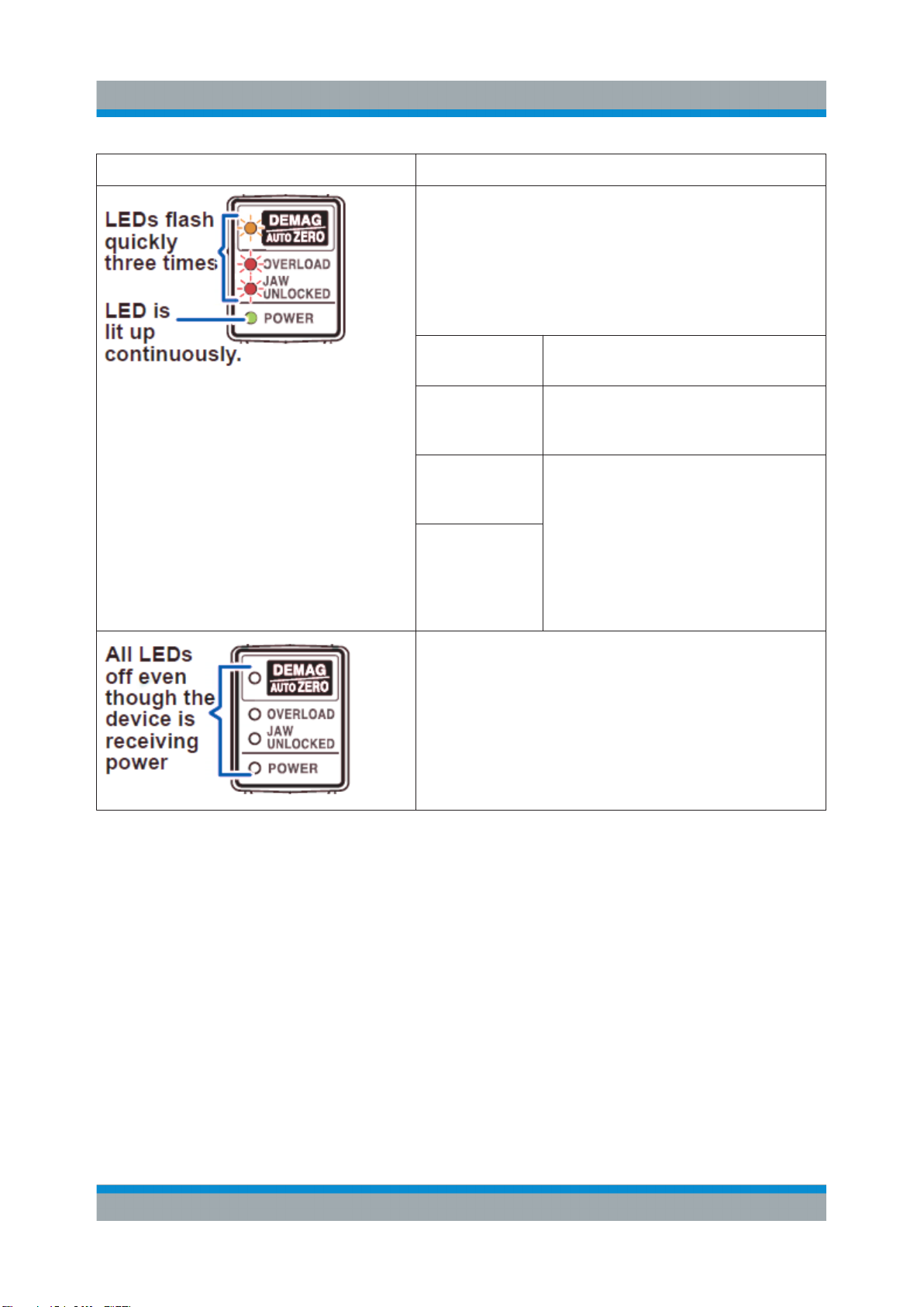
This issue occurs when the DEMAG/ AUTO ZERO
key is pressed under the circumstances described in
the table below.
Demagnetization and automatic zero adjustment
cannot be performed. Perform demagnetization and
zero adjustment again after implementing the remedy described below.
Measuring Procedure
Troubleshooting
Circumstances
When the JAW
UNLOCKED
LED is lit up
When the
OVERLOAD
LED is flashing
When a current of 0.5
A (RMS) or
greater has
been detected
The device has malfunctioned. Send it to the service
center for repair.
Remedy
Lock the sensor head. (Press the
opening lever until the JAW
UNLOCKED indicator turns off.)
Remove the device from the conductor being measured.
27User Manual 1409.7872.02 ─ 02
Page 37

R&S®RT-ZC30
Maintenance and Service
Returning the Probe for Servicing
4 Maintenance and Service
4.1 Service Strategy
Like all Rohde & Schwarz devices, Rohde & Schwarz probes are of high quality
and require only minimum service and repair. However, if the probe needs to be
serviced, contact your Rohde & Schwarz service center. Return a defective probe
to the Rohde & Schwarz service center for diagnosis and exchange.
You can return the R&S RT-ZC30 current probe for calibration. The service personnel will perform the required tests.
4.2 Returning the Probe for Servicing
Use the original packaging to return your Rohde & Schwarz probe to your
Rohde & Schwarz service center. A list of all service centers is available on
www.services.rohde-schwarz.com.
If you cannot use the original packaging, consider the following:
1. Use a sufficiently sized box.
2. Protect the probe from damage and moisture (e.g. with bubble wrap).
3. Use some kind of protective material (e.g. crumpled newspaper) to stabilize
the probe inside the box.
4. Seal the box with tape.
5. Address the package to your nearest Rohde & Schwarz service center.
28User Manual 1409.7872.02 ─ 02
Page 38
R&S®RT-ZC30
Maintenance and Service
Discarding the Probe
4.3 Cleaning
Device damage caused by cleaning agents
Cleaning agents contain substances that may damage the device; for
example, solvent may damage the labeling or plastic parts.
Never use cleaning agents such as solvents (thinners, acetone, etc.), acids,
bases or other substances
Device damage caused by static electricity
Before cleaning the facing surfaces of the sensor head, discharge any static
electricity at your hands. Thus you ensure that no high voltage caused by
static electricity is applied to the device. Application of a high voltage to the
device may damage the internal Hall elements or circuitry. You can attract
static electricity to your hands by touching a nearby metal object.
To clean the exterior of the probe, use a soft cloth moistened with either distilled
water or isopropyl alcohol. Before using the probe again, make sure to dry it completely.
4.4 Calibration Interval
The recommended calibration interval for R&S RT-ZC30 current probe is two
years. For servicing, send the probe to your nearest Rohde & Schwarz service
center (see Chapter 4.2, "Returning the Probe for Servicing", on page 28).
4.5 Discarding the Probe
Handle and dispose the probe in accordance with local regulations.
29User Manual 1409.7872.02 ─ 02
Page 39
R&S®RT-ZC30
R&S RT-ZA13 Probe Power Supply
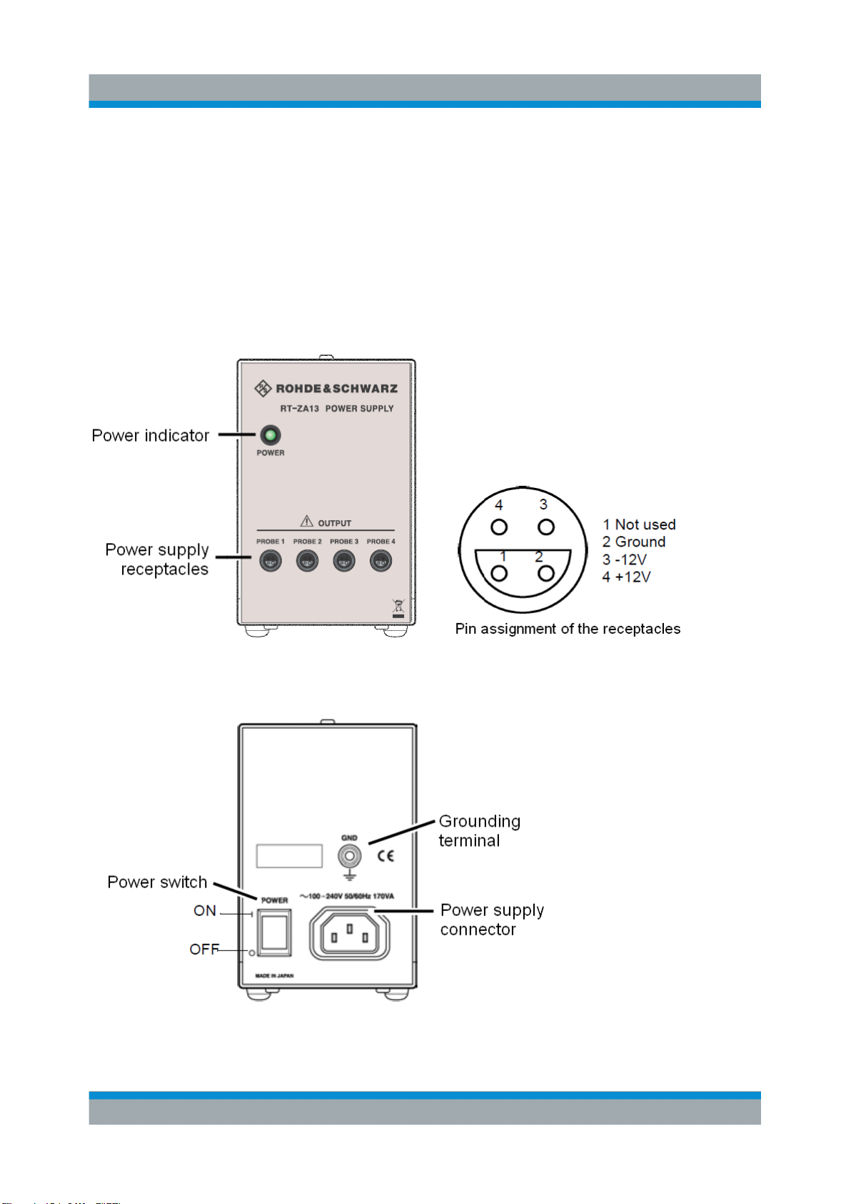
5 R&S RT-ZA13 Probe Power Supply
This unit is a special-purpose power supply for the R&S RT-ZC10 and R&S RTZC20 current probes.
You can connect up to four current probes to the power supply.
Front view
Rear view
30User Manual 1409.7872.02 ─ 02
Page 40
AlliCE
Messtechnik GmbH
make ALLICE your partner
ALLICE Messtechnik GmbH
Kelsterbacher Strasse 15-19 60528 Frankfurt am Main
Tel.: +49(0)69-67724-583 Fax: +49(0)69-67724-582
ww w.allice.de
© 2019 Allice Messtechnik GmbH – Alle Rechte vorbehalten.
© 2019 Allice Messtechnik GmbH – All rights reserved
Verwendete Warenzeichen und Schutzrechte sind Eigentum der jeweiligen Hersteller.
Logos and company names listed are trademarks or trade names of their respective owners.
 Loading...