

Page 1

R&S®RTM
Digital Oscilloscope
Getting Started
(=55Ð2)
1305.0566.02 ─ 05
Getting Started
Test & Measurement
Page 2

This manual describes the following R&S®RTM models:
●
R&S®RTM1052 (1305.0008K52)
●
R&S®RTM1054 (1305.0008K54)
The firmware of the instrument makes use of several valuable open source software packages. For information, see the "Open Source
Acknowledgement" on the user documentation CD-ROM (included in delivery).
Rohde & Schwarz would like to thank the open source community for their valuable contribution to embedded computing.
© 2012 Rohde & Schwarz GmbH & Co. KG
Muehldorfstr. 15, 81671 Munich, Germany
Phone: +49 89 41 29 - 0
Fax: +49 89 41 29 12 164
E-mail: info@rohde-schwarz.com
Internet: http://www.rohde-schwarz.com
Printed in Germany – Subject to change – Data without tolerance limits is not binding.
R&S® is a registered trademark of Rohde & Schwarz GmbH & Co. KG.
Trade names are trademarks of the owners.
The following abbreviations are used throughout this manual: R&S®RTM is abbreviated as R&S RTM.
Page 3

Basic Safety Instructions
Always read through and comply with the following safety instructions!
All plants and locations of the Rohde & Schwarz group of companies make every effort to keep the safety
standards of our products up to date and to offer our customers the highest possible degree of safety. Our
products and the auxiliary equipment they require are designed, built and tested in accordance with the
safety standards that apply in each case. Compliance with these standards is continuously monitored by
our quality assurance system. The product described here has been designed, built and tested in
accordance with the EC Certificate of Conformity and has left the manufacturer’s plant in a condition fully
complying with safety standards. To maintain this condition and to ensure safe operation, you must
observe all instructions and warnings provided in this manual. If you have any questions regarding these
safety instructions, the Rohde & Schwarz group of companies will be happy to answer them.
Furthermore, it is your responsibility to use the product in an appropriate manner. This product is designed
for use solely in industrial and laboratory environments or, if expressly permitted, also in the field and must
not be used in any way that may cause personal injury or property damage. You are responsible if the
product is used for any purpose other than its designated purpose or in disregard of the manufacturer's
instructions. The manufacturer shall assume no responsibility for such use of the product.
The product is used for its designated purpose if it is used in accordance with its product documentation
and within its performance limits (see data sheet, documentation, the following safety instructions). Using
the product requires technical skills and, in some cases, a basic knowledge of English. It is therefore
essential that only skilled and specialized staff or thoroughly trained personnel with the required skills be
allowed to use the product. If personal safety gear is required for using Rohde & Schwarz products, this
will be indicated at the appropriate place in the product documentation. Keep the basic safety instructions
and the product documentation in a safe place and pass them on to the subsequent users.
Observing the safety instructions will help prevent personal injury or damage of any kind caused by
dangerous situations. Therefore, carefully read through and adhere to the following safety instructions
before and when using the product. It is also absolutely essential to observe the additional safety
instructions on personal safety, for example, that appear in relevant parts of the product documentation. In
these safety instructions, the word "product" refers to all merchandise sold and distributed by the Rohde &
Schwarz group of companies, including instruments, systems and all accessories. For product-specific
information, see the data sheet and the product documentation.
Safety labels on products
The following safety labels are used on products to warn against risks and dangers.
Symbol Meaning Symbol Meaning
Notice, general danger location
Observe product documentation
Caution when handling heavy equipment Standby indication
Danger of electric shock Direct current (DC)
ON/OFF supply voltage
1171.0000.42 - 07 Page 1
Page 4

asic Safety Instructions
B
Symbol Meaning Symbol Meaning
Warning! Hot surface Alternating current (AC)
Protective conductor terminal Direct/alternating current (DC/AC)
Ground Device fully protected by double (reinforced)
insulation
Ground terminal EU labeling for batteries and accumulators
For additional information, see section "Waste
disposal/Environmental protection", item 1.
Be careful when handling electrostatic sensitive
devices
Warning! Laser radiation
For additional information, see section
"Operation", item 7.
EU labeling for separate collection of electrical
and electronic devices
For additonal information, see section "Waste
disposal/Environmental protection", item 2.
Signal words and their meaning
The following signal words are used in the product documentation in order to warn the reader about risks
and dangers.
Indicates a hazardous situation which, if not avoided, will result in death or
serious injury.
Indicates a hazardous situation which, if not avoided, could result in death or
serious injury.
Indicates a hazardous situation which, if not avoided, could result in minor or
moderate injury.
Indicates information considered important, but not hazard-related, e.g.
messages relating to property damage.
In the product documentation, the word ATTENTION is used synonymously.
These signal words are in accordance with the standard definition for civil applications in the European
Economic Area. Definitions that deviate from the standard definition may also exist in other economic
areas or military applications. It is therefore essential to make sure that the signal words described here
are always used only in connection with the related product documentation and the related product. The
use of signal words in connection with unrelated products or documentation can result in misinterpretation
and in personal injury or material damage.
1171.0000.42 - 07 Page 2
Page 5

asic Safety Instructions
B
Operating states and operating positions
The product may be operated only under the operating conditions and in the positions specified by the
manufacturer, without the product's ventilation being obstructed. If the manufacturer's specifications are
not observed, this can result in electric shock, fire and/or serious personal injury or death. Applicable local
or national safety regulations and rules for the prevention of accidents must be observed in all work
performed.
1. Unless otherwise specified, the following requirements apply to Rohde & Schwarz products:
predefined operating position is always with the housing floor facing down, IP protection 2X, use only
indoors, max. operating altitude 2000 m above sea level, max. transport altitude 4500 m above sea
level. A tolerance of ±10 % shall apply to the nominal voltage and ±5 % to the nominal frequency,
overvoltage category 2, pollution severity 2.
2. Do not place the product on surfaces, vehicles, cabinets or tables that for reasons of weight or stability
are unsuitable for this purpose. Always follow the manufacturer's installation instructions when
installing the product and fastening it to objects or structures (e.g. walls and shelves). An installation
that is not carried out as described in the product documentation could result in personal injury or
even death.
3. Do not place the product on heat-generating devices such as radiators or fan heaters. The ambient
temperature must not exceed the maximum temperature specified in the product documentation or in
the data sheet. Product overheating can cause electric shock, fire and/or serious personal injury or
even death.
Electrical safety
If the information on electrical safety is not observed either at all or to the extent necessary, electric shock,
fire and/or serious personal injury or death may occur.
1. Prior to switching on the product, always ensure that the nominal voltage setting on the product
matches the nominal voltage of the AC supply network. If a different voltage is to be set, the power
fuse of the product may have to be changed accordingly.
2. In the case of products of safety class I with movable power cord and connector, operation is
permitted only on sockets with a protective conductor contact and protective conductor.
3. Intentionally breaking the protective conductor either in the feed line or in the product itself is not
permitted. Doing so can result in the danger of an electric shock from the product. If extension cords
or connector strips are implemented, they must be checked on a regular basis to ensure that they are
safe to use.
4. If there is no power switch for disconnecting the product from the AC supply network, or if the power
switch is not suitable for this purpose, use the plug of the connecting cable to disconnect the product
from the AC supply network. In such cases, always ensure that the power plug is easily reachable and
accessible at all times. For example, if the power plug is the disconnecting device, the length of the
connecting cable must not exceed 3 m. Functional or electronic switches are not suitable for providing
disconnection from the AC supply network. If products without power switches are integrated into
racks or systems, the disconnecting device must be provided at the system level.
5. Never use the product if the power cable is damaged. Check the power cables on a regular basis to
ensure that they are in proper operating condition. By taking appropriate safety measures and
carefully laying the power cable, ensure that the cable cannot be damaged and that no one can be
hurt by, for example, tripping over the cable or suffering an electric shock.
1171.0000.42 - 07 Page 3
Page 6

asic Safety Instructions
B
6. The product may be operated only from TN/TT supply networks fuse-protected with max. 16 A (higher
fuse only after consulting with the Rohde & Schwarz group of companies).
7. Do not insert the plug into sockets that are dusty or dirty. Insert the plug firmly and all the way into the
socket provided for this purpose. Otherwise, sparks that result in fire and/or injuries may occur.
8. Do not overload any sockets, extension cords or connector strips; doing so can cause fire or electric
hocks.
s
9. For measurements in circuits with voltages V
> 30 V, suitable measures (e.g. appropriate
rms
measuring equipment, fuse protection, current limiting, electrical separation, insulation) should be
taken to avoid any hazards.
10. Ensure that the connections with information technology equipment, e.g. PCs or other industrial
computers, comply with the IEC60950-1/EN60950-1 or IEC61010-1/EN 61010-1 standards that apply
in each case.
11. Unless expressly permitted, never remove the cover or any part of the housing while the product is in
operation. Doing so will expose circuits and components and can lead to injuries, fire or damage to the
product.
12. If a product is to be permanently installed, the connection between the protective conductor terminal
on site and the product's protective conductor must be made first before any other connection is
made. The product may be installed and connected only by a licensed electrician.
13. For permanently installed equipment without built-in fuses, circuit breakers or similar protective
devices, the supply circuit must be fuse-protected in such a way that anyone who has access to the
product, as well as the product itself, is adequately protected from injury or damage.
14. Use suitable overvoltage protection to ensure that no overvoltage (such as that caused by a bolt of
lightning) can reach the product. Otherwise, the person operating the product will be exposed to the
danger of an electric shock.
15. Any object that is not designed to be placed in the openings of the housing must not be used for this
purpose. Doing so can cause short circuits inside the product and/or electric shocks, fire or injuries.
16. Unless specified otherwise, products are not liquid-proof (see also section "Operating states and
operating positions", item 1). Therefore, the equipment must be protected against penetration by
liquids. If the necessary precautions are not taken, the user may suffer electric shock or the product
itself may be damaged, which can also lead to personal injury.
17. Never use the product under conditions in which condensation has formed or can form in or on the
product, e.g. if the product has been moved from a cold to a warm environment. Penetration by water
increases the risk of electric shock.
18. Prior to cleaning the product, disconnect it completely from the power supply (e.g. AC supply network
or battery). Use a soft, non-linting cloth to clean the product. Never use chemical cleaning agents such
as alcohol, acetone or diluents for cellulose lacquers.
Operation
1. Operating the products requires special training and intense concentration. Make sure that persons
who use the products are physically, mentally and emotionally fit enough to do so; otherwise, injuries
or material damage may occur. It is the responsibility of the employer/operator to select suitable
personnel for operating the products.
1171.0000.42 - 07 Page 4
Page 7

Basic Safety Instructions
2. Before you move or transport the product, read and observe the section titled "Transport".
3. As with all industrially manufactured goods, the use of substances that induce an allergic reaction
(allergens) such as nickel cannot be generally excluded. If you develop an allergic reaction (such as a
skin rash, frequent sneezing, red eyes or respiratory difficulties) when using a Rohde & Schwarz
product, consult a physician immediately to determine the cause and to prevent health problems or
stress.
4. Before you start processing the product mechanically and/or thermally, or before you take it apart, be
sure to read and pay special attention to the section titled "Waste disposal/Environmental protection",
item 1.
5. Depending on the function, certain products such as RF radio equipment can produce an elevated
level of electromagnetic radiation. Considering that unborn babies require increased protection,
pregnant women must be protected by appropriate measures. Persons with pacemakers may also be
exposed to risks from electromagnetic radiation. The employer/operator must evaluate workplaces
where there is a special risk of exposure to radiation and, if necessary, take measures to avert the
potential danger.
6. Should a fire occur, the product may release hazardous substances (gases, fluids, etc.) that can
cause health problems. Therefore, suitable measures must be taken, e.g. protective masks and
protective clothing must be worn.
7. Laser products are given warning labels that are standardized according to their laser class. Lasers
can cause biological harm due to the properties of their radiation and due to their extremely
concentrated electromagnetic power. If a laser product (e.g. a CD/DVD drive) is integrated into a
Rohde & Schwarz product, absolutely no other settings or functions may be used as described in the
product documentation. The objective is to prevent personal injury (e.g. due to laser beams).
8. EMC classes (in line with EN 55011/CISPR 11,
EN 55032/CISPR 32)
Class A equipment:
Equipment suitable for use in all environments except residential environments and environments
that are directly connected to a low-voltage supply network that supplies residential buildings
Note: Class A equipment is intended for use in an industrial environment. This equipment may
cause radio disturbances in residential environments, due to possible conducted as well as
radiated disturbances. In this case, the operator may be required to take appropriate measures to
eliminate these disturbances.
Class B equipment:
Equipment suitable for use in residential environments and environments that are directly
connected to a low-voltage supply network that supplies residential buildings
Repair and service
1. The product may be opened only by authorized, specially trained personnel. Before any work is
performed on the product or before the product is opened, it must be disconnected from the AC supply
network. Otherwise, personnel will be exposed to the risk of an electric shock.
and analogously with EN 55022/CISPR 22,
1171.0000.42 - 07 Page 5
Page 8

asic Safety Instructions
B
2. Adjustments, replacement of parts, maintenance and repair may be performed only by electrical
experts authorized by Rohde & Schwarz. Only original parts may be used for replacing parts relevant
to safety (e.g. power switches, power transformers, fuses). A safety test must always be performed
after parts relevant to safety have been replaced (visual inspection, protective conductor test,
insulation resistance measurement, leakage current measurement, functional test). This helps ensure
the continued safety of the product.
Batteries and rechargeable batteries/cells
If the information regarding batteries and rechargeable batteries/cells is not observed either at all or to the
extent necessary, product users may be exposed to the risk of explosions, fire and/or serious personal
injury, and, in some cases, death. Batteries and rechargeable batteries with alkaline electrolytes (e.g.
lithium cells) must be handled in accordance with the EN 62133 standard.
1. Cells must not be taken apart or crushed.
2. Cells or batteries must not be exposed to heat or fire. Storage in direct sunlight must be avoided.
Keep cells and batteries clean and dry. Clean soiled connectors using a dry, clean cloth.
3. Cells or batteries must not be short-circuited. Cells or batteries must not be stored in a box or in a
drawer where they can short-circuit each other, or where they can be short-circuited by other
conductive materials. Cells and batteries must not be removed from their original packaging until they
are ready to be used.
4. Cells and batteries must not be exposed to any mechanical shocks that are stronger than permitted.
5. If a cell develops a leak, the fluid must not be allowed to come into contact with the skin or eyes. If
contact occurs, wash the affected area with plenty of water and seek medical aid.
6. Improperly replacing or charging cells or batteries that contain alkaline electrolytes (e.g. lithium cells)
can cause explosions. Replace cells or batteries only with the matching Rohde & Schwarz type (see
parts list) in order to ensure the safety of the product.
7. Cells and batteries must be recycled and kept separate from residual waste. Rechargeable batteries
and normal batteries that contain lead, mercury or cadmium are hazardous waste. Observe the
national regulations regarding waste disposal and recycling.
Transport
1. The product may be very heavy. Therefore, the product must be handled with care. In some cases,
the user may require a suitable means of lifting or moving the product (e.g. with a lift-truck) to avoid
back or other physical injuries.
2. Handles on the products are designed exclusively to enable personnel to transport the product. It is
therefore not permissible to use handles to fasten the product to or on transport equipment such as
cranes, fork lifts, wagons, etc. The user is responsible for securely fastening the products to or on the
means of transport or lifting. Observe the safety regulations of the manufacturer of the means of
transport or lifting. Noncompliance can result in personal injury or material damage.
3. If you use the product in a vehicle, it is the sole responsibility of the driver to drive the vehicle safely
and properly. The manufacturer assumes no responsibility for accidents or collisions. Never use the
product in a moving vehicle if doing so could distract the driver of the vehicle. Adequately secure the
product in the vehicle to prevent injuries or other damage in the event of an accident.
1171.0000.42 - 07 Page 6
Page 9

nstrucciones de seguridad elementales
I
Waste disposal/Environmental protection
1. Specially marked equipment has a battery or accumulator that must not be disposed of with unsorted
municipal waste, but must be collected separately. It may only be disposed of at a suitable collection
point or via a Rohde & Schwarz customer service center.
2. Waste electrical and electronic equipment must not be disposed of with unsorted municipal waste, but
ust be collected separately.
m
Rohde & Schwarz GmbH & Co. KG has developed a disposal concept and takes full responsibility for
take-back obligations and disposal obligations for manufacturers within the EU. Contact your
Rohde & Schwarz customer service center for environmentally responsible disposal of the product.
3. If products or their components are mechanically and/or thermally processed in a manner that goes
beyond their intended use, hazardous substances (heavy-metal dust such as lead, beryllium, nickel)
may be released. For this reason, the product may only be disassembled by specially trained
personnel. Improper disassembly may be hazardous to your health. National waste disposal
regulations must be observed.
4. If handling the product releases hazardous substances or fuels that must be disposed of in a special
way, e.g. coolants or engine oils that must be replenished regularly, the safety instructions of the
manufacturer of the hazardous substances or fuels and the applicable regional waste disposal
regulations must be observed. Also observe the relevant safety instructions in the product
documentation. The improper disposal of hazardous substances or fuels can cause health problems
and lead to environmental damage.
For additional information about environmental protection, visit the Rohde & Schwarz website.
Instrucciones de seguridad elementales
¡Es imprescindible leer y cumplir las siguientes instrucciones e informaciones de seguridad!
El principio del grupo de empresas Rohde & Schwarz consiste en tener nuestros productos siempre al día
con los estándares de seguridad y de ofrecer a nuestros clientes el máximo grado de seguridad. Nuestros
productos y todos los equipos adicionales son siempre fabricados y examinados según las normas de
seguridad vigentes. Nuestro sistema de garantía de calidad controla constantemente que sean cumplidas
estas normas. El presente producto ha sido fabricado y examinado según el certificado de conformidad
de la UE y ha salido de nuestra planta en estado impecable según los estándares técnicos de seguridad.
Para poder preservar este estado y garantizar un funcionamiento libre de peligros, el usuario deberá
atenerse a todas las indicaciones, informaciones de seguridad y notas de alerta. El grupo de empresas
Rohde & Schwarz está siempre a su disposición en caso de que tengan preguntas referentes a estas
informaciones de seguridad.
Además queda en la responsabilidad del usuario utilizar el producto en la forma debida. Este producto
está destinado exclusivamente al uso en la industria y el laboratorio o, si ha sido expresamente
autorizado, para aplicaciones de campo y de ninguna manera deberá ser utilizado de modo que alguna
persona/cosa pueda sufrir daño. El uso del producto fuera de sus fines definidos o sin tener en cuenta las
instrucciones del fabricante queda en la responsabilidad del usuario. El fabricante no se hace en ninguna
forma responsable de consecuencias a causa del mal uso del producto.
1171.0000.42 - 07 Page 7
Page 10

nstrucciones de seguridad elementales
I
Se parte del uso correcto del producto para los fines definidos si el producto es utilizado conforme a las
indicaciones de la correspondiente documentación del producto y dentro del margen de rendimiento
definido (ver hoja de datos, documentación, informaciones de seguridad que siguen). El uso del producto
hace necesarios conocimientos técnicos y ciertos conocimientos del idioma inglés. Por eso se debe tener
en cuenta que el producto solo pueda ser operado por personal especializado o personas instruidas en
profundidad con las capacidades correspondientes. Si fuera necesaria indumentaria de seguridad para el
so de productos de Rohde & Schwarz, encontraría la información debida en la documentación del
u
producto en el capítulo correspondiente. Guarde bien las informaciones de seguridad elementales, así
como la documentación del producto, y entréguelas a usuarios posteriores.
Tener en cuenta las informaciones de seguridad sirve para evitar en lo posible lesiones o daños por
peligros de toda clase. Por eso es imprescindible leer detalladamente y comprender por completo las
siguientes informaciones de seguridad antes de usar el producto, y respetarlas durante el uso del
producto. Deberán tenerse en cuenta todas las demás informaciones de seguridad, como p. ej. las
referentes a la protección de personas, que encontrarán en el capítulo correspondiente de la
documentación del producto y que también son de obligado cumplimiento. En las presentes
informaciones de seguridad se recogen todos los objetos que distribuye el grupo de empresas
Rohde & Schwarz bajo la denominación de "producto", entre ellos también aparatos, instalaciones así
como toda clase de accesorios. Los datos específicos del producto figuran en la hoja de datos y en la
documentación del producto.
Señalización de seguridad de los productos
Las siguientes señales de seguridad se utilizan en los productos para advertir sobre riesgos y peligros.
Símbolo Significado Símbolo Significado
Aviso: punto de peligro general
Observar la documentación del producto
Atención en el manejo de dispositivos de peso
elevado
Peligro de choque eléctrico Corriente continua (DC)
Advertencia: superficie caliente Corriente alterna (AC)
Conexión a conductor de protección Corriente continua / Corriente alterna (DC/AC)
Conexión a tierra El aparato está protegido en su totalidad por un
Tensión de alimentación de PUESTA EN
MARCHA / PARADA
Indicación de estado de espera (standby)
aislamiento doble (reforzado)
Conexión a masa Distintivo de la UE para baterías y
acumuladores
Más información en la sección
"Eliminación/protección del medio ambiente",
punto 1.
1171.0000.42 - 07 Page 8
Page 11

nstrucciones de seguridad elementales
I
Símbolo Significado Símbolo Significado
Aviso: Cuidado en el manejo de dispositivos
sensibles a la electrostática (ESD)
Advertencia: rayo láser
Más información en la sección
"Funcionamiento", punto 7.
Distintivo de la UE para la eliminación por
separado de dispositivos eléctricos y
electrónicos
Más información en la sección
"Eliminación/protección del medio ambiente",
punto 2.
Palabras de señal y su significado
En la documentación del producto se utilizan las siguientes palabras de señal con el fin de advertir contra
riesgos y peligros.
Indica una situación de peligro que, si no se evita, causa lesiones
graves o incluso la muerte.
Indica una situación de peligro que, si no se evita, puede causar
lesiones graves o incluso la muerte.
Indica una situación de peligro que, si no se evita, puede causar
lesiones leves o moderadas.
Indica información que se considera importante, pero no en relación
con situaciones de peligro; p. ej., avisos sobre posibles daños
materiales.
En la documentación del producto se emplea de forma sinónima el
término CUIDADO.
Las palabras de señal corresponden a la definición habitual para aplicaciones civiles en el área
económica europea. Pueden existir definiciones diferentes a esta definición en otras áreas económicas o
en aplicaciones militares. Por eso se deberá tener en cuenta que las palabras de señal aquí descritas
sean utilizadas siempre solamente en combinación con la correspondiente documentación del producto y
solamente en combinación con el producto correspondiente. La utilización de las palabras de señal en
combinación con productos o documentaciones que no les correspondan puede llevar a interpretaciones
equivocadas y tener por consecuencia daños en personas u objetos.
Estados operativos y posiciones de funcionamiento
El producto solamente debe ser utilizado según lo indicado por el fabricante respecto a los estados
operativos y posiciones de funcionamiento sin que se obstruya la ventilación. Si no se siguen las
indicaciones del fabricante, pueden producirse choques eléctricos, incendios y/o lesiones graves con
posible consecuencia de muerte. En todos los trabajos deberán ser tenidas en cuenta las normas
nacionales y locales de seguridad del trabajo y de prevención de accidentes.
1171.0000.42 - 07 Page 9
Page 12

nstrucciones de seguridad elementales
I
1. Si no se convino de otra manera, es para los productos Rohde & Schwarz válido lo que sigue:
como posición de funcionamiento se define por principio la posición con el suelo de la caja para
abajo, modo de protección IP 2X, uso solamente en estancias interiores, utilización hasta 2000 m
sobre el nivel del mar, transporte hasta 4500 m sobre el nivel del mar. Se aplicará una tolerancia de
±10 % sobre el voltaje nominal y de ±5 % sobre la frecuencia nominal. Categoría de sobrecarga
eléctrica 2, índice de suciedad 2.
2. No sitúe el producto encima de superficies, vehículos, estantes o mesas, que por sus características
de peso o de estabilidad no sean aptos para él. Siga siempre las instrucciones de instalación del
fabricante cuando instale y asegure el producto en objetos o estructuras (p. ej. paredes y estantes). Si
se realiza la instalación de modo distinto al indicado en la documentación del producto, se pueden
causar lesiones o, en determinadas circunstancias, incluso la muerte.
3. No ponga el producto sobre aparatos que generen calor (p. ej. radiadores o calefactores). La
temperatura ambiente no debe superar la temperatura máxima especificada en la documentación del
producto o en la hoja de datos. En caso de sobrecalentamiento del producto, pueden producirse
choques eléctricos, incendios y/o lesiones graves con posible consecuencia de muerte.
Seguridad eléctrica
Si no se siguen (o se siguen de modo insuficiente) las indicaciones del fabricante en cuanto a seguridad
eléctrica, pueden producirse choques eléctricos, incendios y/o lesiones graves con posible consecuencia
de muerte.
1. Antes de la puesta en marcha del producto se deberá comprobar siempre que la tensión
preseleccionada en el producto coincida con la de la red de alimentación eléctrica. Si es necesario
modificar el ajuste de tensión, también se deberán cambiar en caso dado los fusibles
correspondientes del producto.
2. Los productos de la clase de protección I con alimentación móvil y enchufe individual solamente
podrán enchufarse a tomas de corriente con contacto de seguridad y con conductor de protección
conectado.
3. Queda prohibida la interrupción intencionada del conductor de protección, tanto en la toma de
corriente como en el mismo producto. La interrupción puede tener como consecuencia el riesgo de
que el producto sea fuente de choques eléctricos. Si se utilizan cables alargadores o regletas de
enchufe, deberá garantizarse la realización de un examen regular de los mismos en cuanto a su
estado técnico de seguridad.
4. Si el producto no está equipado con un interruptor para desconectarlo de la red, o bien si el
interruptor existente no resulta apropiado para la desconexión de la red, el enchufe del cable de
conexión se deberá considerar como un dispositivo de desconexión.
El dispositivo de desconexión se debe poder alcanzar fácilmente y debe estar siempre bien accesible.
Si, p. ej., el enchufe de conexión a la red es el dispositivo de desconexión, la longitud del cable de
conexión no debe superar 3 m).
Los interruptores selectores o electrónicos no son aptos para el corte de la red eléctrica. Si se
integran productos sin interruptor en bastidores o instalaciones, se deberá colocar el interruptor en el
nivel de la instalación.
5. No utilice nunca el producto si está dañado el cable de conexión a red. Compruebe regularmente el
correcto estado de los cables de conexión a red. Asegúrese, mediante las medidas de protección y
de instalación adecuadas, de que el cable de conexión a red no pueda ser dañado o de que nadie
pueda ser dañado por él, p. ej. al tropezar o por un choque eléctrico.
1171.0000.42 - 07 Page 10
Page 13

nstrucciones de seguridad elementales
I
6. Solamente está permitido el funcionamiento en redes de alimentación TN/TT aseguradas con fusibles
de 16 A como máximo (utilización de fusibles de mayor amperaje solo previa consulta con el grupo de
empresas Rohde & Schwarz).
7. Nunca conecte el enchufe en tomas de corriente sucias o llenas de polvo. Introduzca el enchufe por
completo y fuertemente en la toma de corriente. La no observación de estas medidas puede provocar
chispas, fuego y/o lesiones.
8. No sobrecargue las tomas de corriente, los cables alargadores o las regletas de enchufe ya que esto
podría causar fuego o choques eléctricos.
9. En las mediciones en circuitos de corriente con una tensión U
> 30 V se deberán tomar las medidas
eff
apropiadas para impedir cualquier peligro (p. ej. medios de medición adecuados, seguros, limitación
de tensión, corte protector, aislamiento etc.).
10. Para la conexión con dispositivos informáticos como un PC o un ordenador industrial, debe
comprobarse que éstos cumplan los estándares IEC60950-1/EN60950-1 o IEC61010-1/EN 61010-1
válidos en cada caso.
11. A menos que esté permitido expresamente, no retire nunca la tapa ni componentes de la carcasa
mientras el producto esté en servicio. Esto pone a descubierto los cables y componentes eléctricos y
puede causar lesiones, fuego o daños en el producto.
12. Si un producto se instala en un lugar fijo, se deberá primero conectar el conductor de protección fijo
con el conductor de protección del producto antes de hacer cualquier otra conexión. La instalación y
la conexión deberán ser efectuadas por un electricista especializado.
13. En el caso de dispositivos fijos que no estén provistos de fusibles, interruptor automático ni otros
mecanismos de seguridad similares, el circuito de alimentación debe estar protegido de modo que
todas las personas que puedan acceder al producto, así como el producto mismo, estén a salvo de
posibles daños.
14. Todo producto debe estar protegido contra sobretensión (debida p. ej. a una caída del rayo) mediante
los correspondientes sistemas de protección. Si no, el personal que lo utilice quedará expuesto al
peligro de choque eléctrico.
15. No debe introducirse en los orificios de la caja del aparato ningún objeto que no esté destinado a ello.
Esto puede producir cortocircuitos en el producto y/o puede causar choques eléctricos, fuego o
lesiones.
16. Salvo indicación contraria, los productos no están impermeabilizados (ver también el capítulo
"Estados operativos y posiciones de funcionamiento", punto 1). Por eso es necesario tomar las
medidas necesarias para evitar la entrada de líquidos. En caso contrario, existe peligro de choque
eléctrico para el usuario o de daños en el producto, que también pueden redundar en peligro para las
personas.
17. No utilice el producto en condiciones en las que pueda producirse o ya se hayan producido
condensaciones sobre el producto o en el interior de éste, como p. ej. al desplazarlo de un lugar frío a
otro caliente. La entrada de agua aumenta el riesgo de choque eléctrico.
18. Antes de la limpieza, desconecte por completo el producto de la alimentación de tensión (p. ej. red de
alimentación o batería). Realice la limpieza de los aparatos con un paño suave, que no se deshilache.
No utilice bajo ningún concepto productos de limpieza químicos como alcohol, acetona o diluyentes
para lacas nitrocelulósicas.
1171.0000.42 - 07 Page 11
Page 14

nstrucciones de seguridad elementales
I
Funcionamiento
1. El uso del producto requiere instrucciones especiales y una alta concentración durante el manejo.
Debe asegurarse que las personas que manejen el producto estén a la altura de los requerimientos
necesarios en cuanto a aptitudes físicas, psíquicas y emocionales, ya que de otra manera no se
pueden excluir lesiones o daños de objetos. El empresario u operador es responsable de seleccionar
el personal usuario apto para el manejo del producto.
2. Antes de desplazar o transportar el producto, lea y tenga en cuenta el capítulo "Transporte".
3. Como con todo producto de fabricación industrial no puede quedar excluida en general la posibilidad
de que se produzcan alergias provocadas por algunos materiales empleados Slos llamados
alérgenos (p. ej. el níquel)S. Si durante el manejo de productos Rohde & Schwarz se producen
reacciones alérgicas, como p. ej. irritaciones cutáneas, estornudos continuos, enrojecimiento de la
conjuntiva o dificultades respiratorias, debe avisarse inmediatamente a un médico para investigar las
causas y evitar cualquier molestia o daño a la salud.
4. Antes de la manipulación mecánica y/o térmica o el desmontaje del producto, debe tenerse en cuenta
imprescindiblemente el capítulo "Eliminación/protección del medio ambiente", punto 1.
5. Ciertos productos, como p. ej. las instalaciones de radiocomunicación RF, pueden a causa de su
función natural, emitir una radiación electromagnética aumentada. Deben tomarse todas las medidas
necesarias para la protección de las mujeres embarazadas. También las personas con marcapasos
pueden correr peligro a causa de la radiación electromagnética. El empresario/operador tiene la
obligación de evaluar y señalizar las áreas de trabajo en las que exista un riesgo elevado de
exposición a radiaciones.
6. Tenga en cuenta que en caso de incendio pueden desprenderse del producto sustancias tóxicas
(gases, líquidos etc.) que pueden generar daños a la salud. Por eso, en caso de incendio deben
usarse medidas adecuadas, como p. ej. máscaras antigás e indumentaria de protección.
7. Los productos con láser están provistos de indicaciones de advertencia normalizadas en función de la
clase de láser del que se trate. Los rayos láser pueden provocar daños de tipo biológico a causa de
las propiedades de su radiación y debido a su concentración extrema de potencia electromagnética.
En caso de que un producto Rohde & Schwarz contenga un producto láser (p. ej. un lector de
CD/DVD), no debe usarse ninguna otra configuración o función aparte de las descritas en la
documentación del producto, a fin de evitar lesiones (p. ej. debidas a irradiación láser).
8. Clases de compatibilidad electromagnética (conforme a EN 55011 / CISPR 11; y en analogía con EN
55022 / CISPR 22, EN 55032 / CISPR 32)
Aparato de clase A:
Aparato adecuado para su uso en todos los entornos excepto en los residenciales y en aquellos
conectados directamente a una red de distribución de baja tensión que suministra corriente a
edificios residenciales.
Nota: Los aparatos de clase A están destinados al uso en entornos industriales. Estos aparatos
pueden causar perturbaciones radioeléctricas en entornos residenciales debido a posibles
perturbaciones guiadas o radiadas. En este caso, se le podrá solicitar al operador que tome las
medidas adecuadas para eliminar estas perturbaciones.
Aparato de clase B:
Aparato adecuado para su uso en entornos residenciales, así como en aquellos conectados
directamente a una red de distribución de baja tensión que suministra corriente a edificios
residenciales.
1171.0000.42 - 07 Page 12
Page 15

nstrucciones de seguridad elementales
I
Reparación y mantenimiento
1. El producto solamente debe ser abierto por personal especializado con autorización para ello. Antes
de manipular el producto o abrirlo, es obligatorio desconectarlo de la tensión de alimentación, para
evitar toda posibilidad de choque eléctrico.
2. El ajuste, el cambio de partes, el mantenimiento y la reparación deberán ser efectuadas solamente
or electricistas autorizados por Rohde & Schwarz. Si se reponen partes con importancia para los
p
aspectos de seguridad (p. ej. el enchufe, los transformadores o los fusibles), solamente podrán ser
sustituidos por partes originales. Después de cada cambio de partes relevantes para la seguridad
deberá realizarse un control de seguridad (control a primera vista, control del conductor de
protección, medición de resistencia de aislamiento, medición de la corriente de fuga, control de
funcionamiento). Con esto queda garantizada la seguridad del producto.
Baterías y acumuladores o celdas
Si no se siguen (o se siguen de modo insuficiente) las indicaciones en cuanto a las baterías y
acumuladores o celdas, pueden producirse explosiones, incendios y/o lesiones graves con posible
consecuencia de muerte. El manejo de baterías y acumuladores con electrolitos alcalinos (p. ej. celdas de
litio) debe seguir el estándar EN 62133.
1. No deben desmontarse, abrirse ni triturarse las celdas.
2. Las celdas o baterías no deben someterse a calor ni fuego. Debe evitarse el almacenamiento a la luz
directa del sol. Las celdas y baterías deben mantenerse limpias y secas. Limpiar las conexiones
sucias con un paño seco y limpio.
3. Las celdas o baterías no deben cortocircuitarse. Es peligroso almacenar las celdas o baterías en
estuches o cajones en cuyo interior puedan cortocircuitarse por contacto recíproco o por contacto con
otros materiales conductores. No deben extraerse las celdas o baterías de sus embalajes originales
hasta el momento en que vayan a utilizarse.
4. Las celdas o baterías no deben someterse a impactos mecánicos fuertes indebidos.
5. En caso de falta de estanqueidad de una celda, el líquido vertido no debe entrar en contacto con la
piel ni los ojos. Si se produce contacto, lavar con agua abundante la zona afectada y avisar a un
médico.
6. En caso de cambio o recarga inadecuados, las celdas o baterías que contienen electrolitos alcalinos
(p. ej. las celdas de litio) pueden explotar. Para garantizar la seguridad del producto, las celdas o
baterías solo deben ser sustituidas por el tipo Rohde & Schwarz correspondiente (ver lista de
recambios).
7. Las baterías y celdas deben reciclarse y no deben tirarse a la basura doméstica. Las baterías o
acumuladores que contienen plomo, mercurio o cadmio deben tratarse como residuos especiales.
Respete en esta relación las normas nacionales de eliminación y reciclaje.
Transporte
1. El producto puede tener un peso elevado. Por eso es necesario desplazarlo o transportarlo con
precaución y, si es necesario, usando un sistema de elevación adecuado (p. ej. una carretilla
elevadora), a fin de evitar lesiones en la espalda u otros daños personales.
1171.0000.42 - 07 Page 13
Page 16

nstrucciones de seguridad elementales
I
2. Las asas instaladas en los productos sirven solamente de ayuda para el transporte del producto por
personas. Por eso no está permitido utilizar las asas para la sujeción en o sobre medios de transporte
como p. ej. grúas, carretillas elevadoras de horquilla, carros etc. Es responsabilidad suya fijar los
productos de manera segura a los medios de transporte o elevación. Para evitar daños personales o
daños en el producto, siga las instrucciones de seguridad del fabricante del medio de transporte o
elevación utilizado.
3. Si se utiliza el producto dentro de un vehículo, recae de manera exclusiva en el conductor la
responsabilidad de conducir el vehículo de manera segura y adecuada. El fabricante no asumirá
ninguna responsabilidad por accidentes o colisiones. No utilice nunca el producto dentro de un
vehículo en movimiento si esto pudiera distraer al conductor. Asegure el producto dentro del vehículo
debidamente para evitar, en caso de un accidente, lesiones u otra clase de daños.
Eliminación/protección del medio ambiente
1. Los dispositivos marcados contienen una batería o un acumulador que no se debe desechar con los
residuos domésticos sin clasificar, sino que debe ser recogido por separado. La eliminación se debe
efectuar exclusivamente a través de un punto de recogida apropiado o del servicio de atención al
cliente de Rohde & Schwarz.
2. Los dispositivos eléctricos usados no se deben desechar con los residuos domésticos sin clasificar,
sino que deben ser recogidos por separado.
Rohde & Schwarz GmbH & Co.KG ha elaborado un concepto de eliminación de residuos y asume
plenamente los deberes de recogida y eliminación para los fabricantes dentro de la UE. Para
desechar el producto de manera respetuosa con el medio ambiente, diríjase a su servicio de atención
al cliente de Rohde & Schwarz.
3. Si se trabaja de manera mecánica y/o térmica cualquier producto o componente más allá del
funcionamiento previsto, pueden liberarse sustancias peligrosas (polvos con contenido de metales
pesados como p. ej. plomo, berilio o níquel). Por eso el producto solo debe ser desmontado por
personal especializado con formación adecuada. Un desmontaje inadecuado puede ocasionar daños
para la salud. Se deben tener en cuenta las directivas nacionales referentes a la eliminación de
residuos.
4. En caso de que durante el trato del producto se formen sustancias peligrosas o combustibles que
deban tratarse como residuos especiales (p. ej. refrigerantes o aceites de motor con intervalos de
cambio definidos), deben tenerse en cuenta las indicaciones de seguridad del fabricante de dichas
sustancias y las normas regionales de eliminación de residuos. Tenga en cuenta también en caso
necesario las indicaciones de seguridad especiales contenidas en la documentación del producto. La
eliminación incorrecta de sustancias peligrosas o combustibles puede causar daños a la salud o
daños al medio ambiente.
Se puede encontrar más información sobre la protección del medio ambiente en la página web de
Rohde & Schwarz.
1171.0000.42 - 07 Page 14
Page 17

Customer Support
Technical support – where and when you need it
For quick, expert help with any Rohde & Schwarz equipment, contact one of our Customer Support
Centers. A team of highly qualified engineers provides telephone support and will work with you to find a
solution to your query on any aspect of the operation, programming or applications of Rohde & Schwarz
equipment.
Up-to-date information and upgrades
To keep your instrument up-to-date and to be informed about new application notes related to your
instrument, please send an e-mail to the Customer Support Center stating your instrument and your wish.
We will take care that you will get the right information.
Europe, Africa, Middle East
North America
Latin America
Asia/Pacific
China
Phone +49 89 4129 12345
customersupport@rohde-schwarz.com
Phone 1-888-TEST-RSA (1-888-837-8772)
customer.support@rsa.rohde-schwarz.com
Phone +1-410-910-7988
customersupport.la@rohde-schwarz.com
Phone +65 65 13 04 88
customersupport.asia@rohde-schwarz.com
Phone +86-800-810-8228 /
+86-400-650-5896
customersupport.china@rohde-schwarz.com
1171.0200.22-06.00
Page 18

R&S®RTM
Contents
Contents
1 Preface....................................................................................................5
1.1 Key Features..................................................................................................................5
1.2 Documentation Overview.............................................................................................5
1.3 Conventions Used in the Documentation...................................................................6
1.3.1 Typographical Conventions.............................................................................................6
2 Preparing for Use...................................................................................8
2.1 Unpacking and Checking the Instrument...................................................................8
2.2 Positioning the instrument...........................................................................................9
2.2.1 Standalone operation......................................................................................................9
2.2.2 Rackmounting...............................................................................................................10
2.3 Starting the Instrument...............................................................................................10
2.3.1 Powering On.................................................................................................................10
2.3.2 Starting Up and Shutting Down.....................................................................................11
2.3.3 Powering Off.................................................................................................................11
2.3.4 EMI Suppression...........................................................................................................12
2.4 Connecting External Devices.....................................................................................12
3 Instrument Tour....................................................................................13
3.1 Front Panel..................................................................................................................13
3.1.1 SETUP Controls............................................................................................................14
3.1.2 MEASURE Keys...........................................................................................................15
3.1.3 NAVIGATION Controls..................................................................................................15
3.1.4 ANALYZE Keys.............................................................................................................16
3.1.5 TRIGGER Controls.......................................................................................................17
3.1.6 HORIZONTAL Controls.................................................................................................18
3.1.7 VERTICAL Controls......................................................................................................19
3.1.8 SEARCH Keys..............................................................................................................20
3.1.9 Input Channels..............................................................................................................21
3.1.10 Front Connectors..........................................................................................................22
3.2 Rear Panel....................................................................................................................22
4 Trying Out the Instrument...................................................................25
3Getting Started 1305.0566.02 ─ 05
Page 19

R&S®RTM
Contents
4.1 Displaying a Basic Signal...........................................................................................25
4.2 Zooming into the Display Using Markers.................................................................26
4.3 Showing Basic Measurement Results......................................................................27
4.4 Performing Cursor Measurements............................................................................29
4.5 Using Mathematical Functions..................................................................................31
4.6 Printing Results...........................................................................................................34
4.7 Storing Data.................................................................................................................35
5 Operating the Instrument....................................................................36
5.1 Understanding Display Information..........................................................................36
5.2 Working with Waveforms...........................................................................................38
5.3 Accessing the Functionality......................................................................................38
5.4 Entering Data...............................................................................................................40
5.5 Getting Help.................................................................................................................41
6 Instrument Setup..................................................................................43
6.1 Defining General Instrument Settings.......................................................................43
6.1.1 Setting Data and Time..................................................................................................43
6.1.2 Configuring Sounds.......................................................................................................43
6.1.3 Setting the Language....................................................................................................43
6.2 Performing a Self Alignment......................................................................................44
6.3 Adjusting Passive Probes..........................................................................................45
7 Maintenance.........................................................................................47
7.1 Cleaning.......................................................................................................................47
7.2 Storing and Packing...................................................................................................48
7.3 Replacing the Fuses...................................................................................................48
7.4 Data Security...............................................................................................................49
Index......................................................................................................50
4Getting Started 1305.0566.02 ─ 05
Page 20

R&S®RTM
Preface
Key Features
1 Preface
1.1 Key Features
The R&S RTM Digital Oscilloscope is a general purpose instrument with excellent performance and measurement accuracy:
Very good noise performance
●
Excellent channel-to-channel isolation prevents crosstalk between channels
●
Vertical resolution down to 1mV/div without bandwidth limitations to get real mea-
●
surement results
The R&S RTM is easy and quickly to operate because of:
8,4" color display with high resolution
●
Colour coded channels
Flat menu structure
●
Deep Undo and Redo
●
Screenshot at a single key stroke
●
Very fast booting
●
Light-weight, portable design
●
The R&S RTM provides a comprehensive functional set. Besides the usual features
known from similar scopes, it has some very useful unique functions:
Quick Measurements: most important measurement results are available at a single
●
key stroke
Sophisticated cursor measurements: special measurement tpyes and features for
●
quick and easy cursor positioning
Acquisition Modes: Decimation modes like Sample mode, Peak Detect and High
●
Resolution can be combined with waveform arithmetic, for example, Average and
Envelope
Smoothing: averaging for non-perodic signals
●
For a detailed specification refer to the data sheet.
1.2 Documentation Overview
The user documentation delivered with the R&S RTM consists of the following parts:
Online Help system on the instrument
●
"Getting Started" printed manual in English
●
Documentation CD-ROM with:
●
– Getting Started
– User Manual
– Service Manual
5Getting Started 1305.0566.02 ─ 05
Page 21

R&S®RTM
Preface
Conventions Used in the Documentation
– Data sheet and product brochure
– Links to useful sites on the R&S internet
Online Help
The Online Help is embedded in the instrument's firmware. It offers quick, context-sensitive description of the softkeys and front panel controls.
Getting Started
The English edition of this manual is delivered with the instrument in printed form. The
manual is also available in other languages in PDF format on the Documentation CDROM. It provides the information needed to set up and start working with the instrument.
Basic operations and typical measurement examples are described. The manual includes
also general information, e.g., Safety Instructions.
User Manual
The User Manual is available in PDF format - in printable form - on the Documentation
CD-ROM. In this manual, all instrument functions are described in detail. Furthermore, it
provides an introduction to remote control and a complete description of the remote control commands with programming examples. Information on maintenance, instrument
interfaces and error messages is also given.
Service Manual
The Service Manual is available in PDF format - in printable form - on the Documentation
CD-ROM. It informs on how to check compliance with rated specifications, on instrument
function, repair, troubleshooting and fault elimination. It contains all information required
for repairing the instrument by the replacement of modules.
Documentation updates
You can download the newest version of the "Getting Started" and "User Manual" from
the "Downloads > Manuals" section on the Rohde & Schwarz "Scope of the Art" Web
page: http://www.scope-of-the-art.com/product/rtm.html.
The online help is included in the firmware update package. The help has to be updated
separately to get the information suitable for the firmware version. The firmware and help
update package is available in the "Downloads > Firmware" section on the Rohde &
Schwarz "Scope of the Art" Web page.
1.3 Conventions Used in the Documentation
This chapter describes the conventions used throughout this documentation.
1.3.1 Typographical Conventions
The following text markers are used throughout this documentation:
6Getting Started 1305.0566.02 ─ 05
Page 22

R&S®RTM
Preface
Conventions Used in the Documentation
Convention Description
"Graphical user interface elements"
KEYS Key names are written in capital letters.
File names, commands,
program code
Input Input to be entered by the user is displayed in italics.
Links
"References" References to other parts of the documentation are enclosed by quotation
All names of graphical user interface elements on the screen, such as dialog boxes, menus, options, buttons, and softkeys are enclosed by quotation marks.
File names, commands, coding samples and screen output are distinguished by their font.
Links that you can click are displayed in blue font.
marks.
7Getting Started 1305.0566.02 ─ 05
Page 23

R&S®RTM
Preparing for Use
Unpacking and Checking the Instrument
2 Preparing for Use
This section describes the basic steps to be taken when setting up the R&S RTM for the
first time.
Risk of instrument damage
Note that the general safety instructions also contain information on operating conditions
that will prevent damage to the instrument. The instrument's data sheet may contain
additional operating conditions.
Risk of instrument damage during operation
An unsuitable operating site or test setup can cause damage to the instrument and to
connected devices. Ensure the following operating conditions before you switch on the
instrument:
All fan openings are unobstructed and the airflow perforations are unimpeded. The
●
minimum distance from the wall is 10 cm.
The instrument is dry and shows no sign of condensation.
●
The instrument is positioned as described in the following sections.
●
The ambient temperature does not exceed the range specified in the data sheet.
●
Signal levels at the input connectors are all within the specified ranges.
●
Signal outputs are correctly connected and are not overloaded.
●
2.1 Unpacking and Checking the Instrument
To remove the instrument from its packaging and check the equipment for completeness
proceed as follows:
1. Pull off the polyethylene protection pads from the instrument's rear feet and then
carefully remove the pads from the instrument handles at the front.
2. Pull off the corrugated cardboard cover that protects the rear of the instrument.
3. Carefully unthread the corrugated cardboard cover at the front that protects the
instrument handles and remove it.
4. Check the equipment for completeness using the delivery note and the accessory
lists for the various items.
8Getting Started 1305.0566.02 ─ 05
Page 24

R&S®RTM
Preparing for Use
Positioning the instrument
5. Check the instrument for any damage. If there is damage, immediately contact the
carrier who delivered the instrument. Make sure not to discard the box and packing
material.
Packing material
Retain the original packing material. If the instrument needs to be transported or shipped
at a later date, you can use the material to protect the control elements and connectors.
2.2 Positioning the instrument
The instrument is designed for use under laboratory conditions. It can be used in standalone operation on a bench top or can be installed in a rack.
Risk of injury
The instruments are not designed to be stacked on top of each other because their surface area is too small. The instruments must be installed in a rack to avoid the risk of
personal injury and material damage.
2.2.1 Standalone operation
For standalone operation, place the instrument on a horizontal bench with even, flat surface. The instrument can be used in horizontal position, or with the support feet on the
bottom extended.
Risk of injury at the operating site
The feet may fold in if they are not folded out completely or if the instrument is shifted.
This may cause damage or injury.
Fold the feet completely in or completely out to ensure stability of the instrument.
●
Never shift the instrument when the feet are folded out.
When the feet are folded out, do not work under the instrument or place anything
●
underneath.
The feet can break if they are overloaded. The overall load on the folded-out feet
●
must not exceed 200 N.
9Getting Started 1305.0566.02 ─ 05
Page 25

R&S®RTM
Preparing for Use
Starting the Instrument
2.2.2 Rackmounting
The instrument can be installed in a 19" rack mount using a rack adapter kit. The order
No. is given in the data sheet. The installation instructions are part of the adapter kit.
Risk of instrument damage in a rack
An insufficient airflow can cause the instrument to overheat, which may disturb the operation and even cause damage.
Make sure that all fan openings are unobstructed, that the airflow perforations are unimpeded, and that the minimum distance from the wall is 10 cm.
2.3 Starting the Instrument
2.3.1 Powering On
The R&S RTM can be used with different AC power voltages and adapts itself automatically to it. The nominal voltage and frequency ranges are displayed on the rear panel
and quoted in the data sheet.
Risk of injury and instrument damage
The instrument must be used in an appropriate manner to prevent electric shock, fire,
personal injury, or damage.
Do not open the instrument casing.
●
Read and observe the "Basic Safety Instructions" at the beginning of this manual or
●
on the documentation CD-ROM, in addition to the safety instructions in the following
sections. Notice that the data sheet may specify additional operating conditions.
The AC power connector and the main power switch are located on the rear panel of the
instrument.
1. Connect the instrument to the AC power supply using the AC power cable delivered
with the instrument.
2. Switch the main power switch at the rear of the instrument to position I.
10Getting Started 1305.0566.02 ─ 05
Page 26

R&S®RTM
Preparing for Use
Starting the Instrument
You can leave the AC power on permanently to preserve your last instrument settings.
Powering off is required only if the instrument must be completely disconnected from all
power supplies.
2.3.2 Starting Up and Shutting Down
The POWER switch is located in the bottom left corner of the front panel.
To start up the instrument
1.
Make sure that the R&S RTM is connected to the AC power supply and the main
power switch on the rear panel is in position I.
2. Press the POWER key on the front panel.
The instrument performs a system check and then starts the R&S RTM firmware. The
illuminated keys on the front panel light up. If the previous session was terminated
regularly, the oscilloscope uses the last settings.
To shut down the instrument
► Press the POWER key again.
All current settings are saved, and the software shuts down.
2.3.3 Powering Off
Powering off is required only if the instrument must be completely disconnected from all
power supplies.
1. Press the POWER key on the front panel to shut down the instrument.
2. Switch the main power switch at the rear of the instrument to position 0.
3. Disconnect the AC power cable from the AC power supply.
Risk of losing data
If you switch off the running instrument using the rear panel switch or by disconnecting
the power cord, the instrument loses its current settings. Furthermore, program data may
be lost.
Always first press the POWER key to shut down the application properly.
11Getting Started 1305.0566.02 ─ 05
Page 27

R&S®RTM
Preparing for Use
Connecting External Devices
2.3.4 EMI Suppression
To suppress generated Electromagnetic Interference (EMI), operate the instrument only
while it is closed, with all shielding covers fitted. Note the EMC classification in the data
sheet.
Use appropriate shielded cables to ensure successful control of electromagnetic radiation
during operation, especially for the following connector types:
Signal cables: Use shielded cables (coaxial cable, RG58/U). A proper ground con-
●
nection is required. In combination with signal generators, only use double-shielded
cables (RG223/U, RG214/U). The cable should be as short as possible.
USB: Use double-shielded USB cables and ensure that external USB devices comply
●
with EMC regulations.
GPIB (IEEE/IEC 625): Use a double-shielded GPIB cable.
●
LAN: Use CAT6 or CAT7 cables.
●
Observe also the connector, cable, and cable length requirements provided with the
description of the individual connectors. Without special instruction in the manuals, cable
length must not exceed 3 m, and cables must not be used outside buildings.
2.4 Connecting External Devices
The following interfaces for external devices are provided:
● USB connectors, see also chapter 3.1.10, "Front Connectors", on page 22
● Monitor connector, see also chapter 3.2, "Rear Panel", on page 22
Connecting USB Devices
The USB interfaces on the front and rear panels of the R&S RTM allow you to connect
memory sticks for easy transfer of data to/from a computer (e.g. firmware updates) and
a printer for printing out measurement results.
All USB devices can be connected to or disconnected from the instrument during operation. The instrument detects the USB stick or printer as soon as it is connected.
Connecting an External Monitor
You can connect an external monitor to the DVI-D connector on the instrument's rear
panel. You can also connect a VGA monitor using an appropriate adapter.
Connecting a monitor
Before connecting a monitor, make sure that the instrument is switched off. Otherwise,
correct operation cannot be assured.
12Getting Started 1305.0566.02 ─ 05
Page 28

R&S®RTM
Instrument Tour
Front Panel
3 Instrument Tour
This chapter provides an overview of the front and rear panels of the instrument.
3.1 Front Panel
The front panel of the R&S RTM is shown in figure 3-1. The function keys are grouped
in functional blocks to the left and the right of the display.
Fig. 3-1: Front panel of RTM 1054 with 4 input channels
1 = Display
2 = SETUP controls
3 = MEASURE keys
4 = NAVIGATION controls
5 = ANALYZE keys
6 = TRIGGER controls
7 = HORIZONTAL Controls
8 = VERTICAL controls
9 = SEARCH keys
10 = POWER key
11 = Softkeys
12 = Input channels
13 = Connectors for USB and probe compensation
The display and its information is described in chapter 5.1, "Understanding Display Infor-
mation", on page 36. The keys, rotary knobs and connectors are described in the fol-
lowing chapters.
13Getting Started 1305.0566.02 ─ 05
Page 29

R&S®RTM
Instrument Tour
Front Panel
3.1.1 SETUP Controls
The SETUP keys and knob on the left of the display set the instrument to a defined state,
change basic settings, and provide print and help functions.
AUTOSET
Resets the instrument to the default state, analyzes the active channel signals, and
obtains appropriate horizontal, vertical, and trigger settings to display stable waveforms.
PRESET
Resets the instrument to the default state, without analyzing the signal.
FILE
Opens the "File" menu, where you can:
save instrument settings, waveforms, reference waveforms and math waveforms
●
(formularies)
restore (load) data which were saved before
●
manage the data: browse, copy, and delete files, create folders
●
configure screenshot output
●
configure the behaviour of the PRINT key
●
SETUP
Opens the "Setup" menu, where you can:
set language, date and time, and sound feedback
●
configure the printer
●
configure USB, LAN and GBIP interfaces
●
perform self calibration and probe adjustment
●
install updates
●
get information on hardware in case of service
●
PRINT
Starts printing or saving screenshots, waveforms or settings according to the configuration in FILE > "Print-Key".
HELP
Opens the online help. The appropriate help topic appears when you press a key or turn
a knob. To close the online help, press the HELP key again.
DISPLAY
Opens the "Display" menu to configure the appearance of the waveforms, grid, persistence, and also the XY-diagram.
INTENSITY
Adjusts the intensity of the waveforms on the screen or the backlight of the screen. Press
the knob to toggle the settings. The controlled parameter and its value are shown in a
temporary label in the upper right corner of the screen.
14Getting Started 1305.0566.02 ─ 05
Page 30

R&S®RTM
Instrument Tour
Front Panel
3.1.2 MEASURE Keys
The MEASURE functional block provides the automatic and manual measurement functions.
QUICK MEAS
Displays the results of basic automatic measurements for the selected channel in the
result table and directly on the waveform. For voltage measurements, these are: Vp+,
Vp-, Vpp, V RMS, mean, rise time tr, falling time tf, period T and frequency f.
Press the key again to hide the results.
Note: When you activate quick measurements, cursor measurements are automatically
deactivated, as well as the reference and math menus. Deactivate quick measurements
before selecting these functions. Channels other than the selected one are switched off
in quick measurement mode.
MEAS
Opens the "Measurement" menu, where you can configure up to four amplitude and time
measurements, and count pulses.
CURSOR
Opens the "Cursor" menu, where you can set up various manual measurements by
means of cursors.
3.1.3 NAVIGATION Controls
The rotary knob and the navigation keys support the data entry in various ways.
15Getting Started 1305.0566.02 ─ 05
Page 31

R&S®RTM
Instrument Tour
Front Panel
NAVIGATION
The function of this universal rotary knob depends on the usage context:
If a softkey with numerical entry or selection menu is selected, turn the knob to set a
●
value.
Pressing the knob closes the selection menu.
●
If the cursors are on, press the key to select a cursor line. Turn the knob to change
●
the position of the selected cursor line.
● If an input editor is open – on-screen keypad or on-screen keyboard – turn the knob
until the required character is highlighted, then press the knob to apply it.
UNDO
Reverses the last setting actions step by step. The "Undo" is not possible after preset,
load and recall actions, and creating a reference waveform.
REDO
Recovers the undo steps in reverse order.
3.1.4 ANALYZE Keys
The keys in the ANALYZE functional block open various menus for signal analysis.
PROTOCOL
Opens the "Protocol" menu, where you can select and configure serial interfaces and bus
systems.
MASKS
Opens the "Masks" menu to perform a mask test on the selected waveform. Masks are
used for error detection and compliance tests of digital signals.
You can:
run mask tests,
●
configure new masks besed on channel signals,
●
configure actions triggered by mask violation.
●
FFT
The FFT key activates and deactivates a Fast Fourier Transformation (FFT) for the most
recently selected channel and provides functions to configure and display FFTs.
16Getting Started 1305.0566.02 ─ 05
Page 32

R&S®RTM
Instrument Tour
Front Panel
If activated, the FFT key lights up. Two windows are displayed: the signal vs. time window
at the top, and the result window of the FFT analysis at the bottom.
When deactivated, the previous display is restored.
To display the FFT for a different channel, press the corresponding channel key.
3.1.5 TRIGGER Controls
The keys and the rotary knob in the TRIGGER functional block adjust the trigger and start
or stop acquisition.
RUN CONT
Starts and stops the continuous acquisition. A green light indicates a running acquisition.
A red light shows that acquisition is stopped.
The status is also shown at the right end of the information bar: "Run" or "Complete".
RUN Nx SINGLE
Starts a defined number of acquisitions. Press the key again to stop running acquisitions.
To set the number of acquisitions, press the ACQUISITION key and enter "Nx Single".
FORCE
If the acquisition is running in normal mode and no valid trigger occurs, forcing the trigger
provokes an immediate single acquisition. Thus you can confirm that a signal is available
and use the waveform display to determine how to trigger on it.
MODE
Toggles the trigger mode between Auto and Normal. The trigger mode determines the
behaviour of the instrument if no trigger occurs. The current setting is shown in the information bar.
LEVEL
The rotary knob changes the trigger treshold voltage for all trigger types that require a
trigger level.
Turn clockwise to move the trigger level up. At zero-crossing, the knob shortly snaps in
and the setting is kept constant to simplify the zero-setting. Press the knob to set the level
to 50% of the signal amplitude.
17Getting Started 1305.0566.02 ─ 05
Page 33

R&S®RTM
Instrument Tour
Front Panel
If a B-trigger is enabled, the knob can set the level for both the A- and B-trigger. To assign
the level to the A- or B-trigger, use "Trigger Level" in the "Trigger" menu.
SETUP
Opens the "Trigger" menu.
SOURCE
Opens the "Trigger Source" menu. Press the key repeatedly until the required source is
selected. The key lights up in the color of the selected trigger channel. The selected
source is shown in the information bar.
SLOPE
If you have selected "Edge" trigger as trigger type with an analog trigger source, the
SLOPE key toggles the trigger slope. The current setting is shown by an icon in the
information bar.
If a B-trigger is enabled, the key can set the slope for both the A- and B-trigger. To assign
the slope to the A- or B-trigger, use "Trigger Level" in the "Trigger" menu.
3.1.6 HORIZONTAL Controls
The rotary knobs adjust the waveforms in horizontal direction. Here you can also open
the "Acquisition" setup.
POSITION
In a normal waveform window, the rotary knob changes the trigger offset. This is the
horizontal position of the trigger point in relation to the reference point - the zero point of
the grid. Thus, you can set the trigger point even outside the diagram and analyze the
signal some time before or after the trigger.
Turn clockwise to move the position to the right, and press the knob to reset the value.
At zero-crossing, the knob shortly snaps in and the setting is kept constant to simplify the
zero-setting.
If a zoom or FFT window is displayed, the knob can change other specific horizontal
parameters as well. To toggle the parameters, press the SCALE rotary knob.
18Getting Started 1305.0566.02 ─ 05
Page 34

R&S®RTM
Instrument Tour
Front Panel
SCALE
In a normal waveform window, the rotary knob adjusts the time scale of the horizontal
axis for all signals, also known as time base. Turn clockwise to stretch the waveforms the scale value time/div decreases.
If a zoom or FFT window is displayed, press the knob to toggle between the windows and
their horizontal parameters, then turn the knob to adjust the selected scale value. Pressing the SCALE knob toggles also the parameter changed by the POSITION knob.
ACQUISITION
Opens the "Acquisition" menu. Here you control the data processing - how the waveform
is built from the captured ADC samples. The current acquisition mode is shown in the top
information bar; it is the second value from right.
3.1.7 VERTICAL Controls
The keys and knobs in the VERTICAL functional block select a signal and adjust the
vertical scale and position of the parameters of the selected waveform.
CH N
Each channel key turns on an analog channel, selects it, and opens the "Channel" menu
with the vertical settings of the selected channel. The key is illuminated in the channel
color, if the channel is active.
The effect of the keypress depends on state of the channel:
If channel is off: Pressing the key turns the channel on and selects it. The rotary knobs
●
alongside light up in the channel color.
If the channel is on: Pressing the key selects the channel waveform for vertical setup.
●
POSITION / OFFSET
The rotary knob adjusts the vertical position or the DC offset. It lights up in the color of
the selected waveform. Pressing the key toggles the parameter, the current parameter
and its value are shown in a temporary label marked with the channel color.
19Getting Started 1305.0566.02 ─ 05
Page 35

R&S®RTM
Instrument Tour
Front Panel
At zero-crossing, the knob shortly snaps in and the setting is kept constant to simplify the
zero-setting.
Note: By default, offset is disabled. Press the "Offset" softkey in the "Channel" menu to
enable the offset.
SCALE
Sets the vertical scale in Volts per division to change the amplitude of the selected channel, math, or reference waveform. The current value is shown in the waveform label above
the grid. The knob lights up in the color of the selected waveform.
Turn SCALE clockwise to stretch the waveform. Doing so, the scale value V/div decreases. Press the knob to toggle between fine and rough adjustment.
SIGNAL OFF
Turns the selected signal off and selects the next channel, math or reference waveform.
The key lights up in the color of the selected signal and changes the light according to
the new selection.
REF
Provides functions for working with reference waveforms on the instrument.
MATH
Provides functions to create equations and display calculated data.
3.1.8 SEARCH Keys
In the SEARCH functional block you find the zoom, search and markers functionality.
ZOOM
Provides functions for configuring the ZOOM display for detailed signal observation.
20Getting Started 1305.0566.02 ─ 05
Page 36

R&S®RTM
Instrument Tour
Front Panel
SEARCH MENU
Opens the "Search" menu where you can perform a search for various events in an
acquisition - for example, peaks or specific width conditions - and analyze the search
results.
NEXT
Moves the next (right) marker to the reference point of the display or zoom area.
Note: If another marker is available at the right, but currently not visible on the screen, a
small red arrow is displayed at the right edge of the display. If a search is enabled, the
key navigates the search result markers only.
PREV
Moves the previous (left) marker to the reference point of the display or zoom area.
Note: If another marker is available at the left, but currently not visible on the screen, a
small red arrow is displayed at the left edge of the display. If a search is enabled, the key
navigates the search result markers only.
SET
Sets a new marker at the reference point of the display, unless an existing marker is
already set there.
In the display of search results, the marker is set to the search result that is selected in
the "Event Table".
CLEAR
Deletes the marker at the reference point. Use the NEXT and PREV keys to move the
markers to the reference point.
In the display of search results, the marker is removed from the search result that is
selected in the "Event Table".
3.1.9 Input Channels
Input channels are the connectors for active and passive probes. The input impedance
is selectable, the values are 50 Ω and 1 MΩ.
Risk of injury
If the input voltages are higher than 30 V RMS or 42 V peak or 60 V DC, use appropriate
protective measures to preclude direct contact with the measurement setup.
21Getting Started 1305.0566.02 ─ 05
Page 37
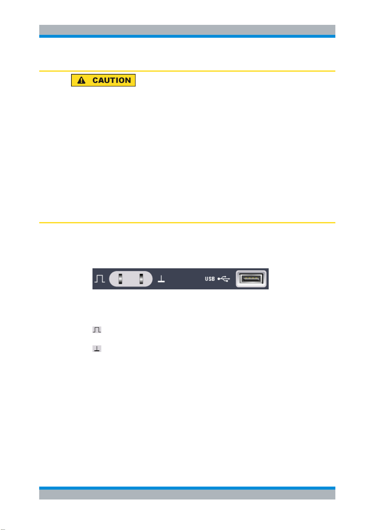
R&S®RTM
Instrument Tour
Rear Panel
Risk of injury and instrument damage
The instrument complies with measuring category I; make sure that the input voltage
does not exceed 200 V peak, 150 V RMS at 1 MΩ input impedance and 5 V RMS at
50 Ω input impedance.
Transient overvoltages must not exceed 200 V peak.
When performing measurements in circuits with transient overvoltages higher than category I, make sure that no such overvoltages reach the R&S RTO input. To ensure this,
use only probes that comply with DIN EN 61010-031. When performing measurements
in category II, III or IV circuits, it is mandatory to insert a probe that appropriately reduces
the voltage so that no overvoltages higher than category I are applied to the instrument.
For detailed information, refer to the documentation and safety information of the probe
manufacturer.
Explanation: Measuring circuits as defined in section 6.7.4 of EN61010-1: Measuring
category I is intended for measurements on circuits which are not connected to the mains
system.
3.1.10 Front Connectors
The most important connectors are placed at the front panel.
PROBE COMPENSATION
Probe compensation terminal to support adjustment of passive probes to the oscilloscope
channel.
Square wave signal for probe compensation with 1 kHz or 1 MHz frequency. You can adjust the signal in SETUP > "Probe Adjust".
Ground connector for probes.
USB
USB type A interface to connect a printer, or a memory stick for storing and reloading
instrument settings and measurement data, and to update the firmware or help. Another
connector of this type is located at the rear panel.
3.2 Rear Panel
Figure 3-2 shows the rear panel of the R&S RTM with its connectors.
22Getting Started 1305.0566.02 ─ 05
Page 38

R&S®RTM
Instrument Tour
Rear Panel
Fig. 3-2: Rear panel view of R&S RTM
1 = AC power supply connector and main power switch
2 = LAN connector
3 = USB connector, type B
4 = USB connector, type A
5 = DVI-D connector for external monitor
6 = External trigger input
AC Supply: mains connector and main power switch
The instrument supports a wide range power supply. It automatically adjusts to the correct
range for the applied voltage. There is no line voltage selector.
The AC main power switch disconnects the instrument from the AC power line.
LAN
8-pin connector RJ-45 used to connect the instrument to a Local Area Network (LAN). It
supports up to 100 Mbit/s.
USB TYPE B
USB (universal serial bus) interface of type B (device USB) to be used for remote control
of the instrument.
Note: Electromagnetic interference (EMI) can affect the measurement results. To avoid
any impact, do not use USB connecting cables exceeding 1 m in length.
USB TYPE A
USB interface of type A (host USB) to connect a printer, or a memory stick for file transfer.
Another connector of this type is located at the front panel.
DVI-D
Digital connector for an external monitor.
23Getting Started 1305.0566.02 ─ 05
Page 39

R&S®RTM
Instrument Tour
Rear Panel
EXTERNAL TRIGGER INPUT
The female connector for external trigger input is used to control the measurement by
means of an external signal. The input impedance is 1 MΩ. The trigger level can be set
from -5 V to 5 V. The maximum input voltage is 150 V peak.
GBIP Interface (Option RTM-B10)
Interface for remote control with GBIP. The option replaces the LAN / USB type B interface module on the rear panel. Thus, remote control is possible either with LAN connection, or with GBIP.
24Getting Started 1305.0566.02 ─ 05
Page 40

R&S®RTM
Trying Out the Instrument
Displaying a Basic Signal
4 Trying Out the Instrument
This chapter introduces the most important functions and settings of the R&S RTM step
by step. The complete description of the functionality and its usage is given in the "User
Manual".
Prerequisites
The instrument is set up, connected to the mains system, and started up as described
●
in chapter 2, "Preparing for Use", on page 8.
A passive probe is connected to the instrument and the probe compensation pins.
●
The probe is compensated as described in chapter 6.3, "Adjusting Passive Probes",
on page 45.
For configuration and measurements described in this chapter, you use the internal calibration signal, so you do not need any additional signal source or instruments. Try out
the following:
● Displaying a Basic Signal........................................................................................25
● Zooming into the Display Using Markers................................................................26
● Showing Basic Measurement Results.....................................................................27
● Performing Cursor Measurements..........................................................................29
● Using Mathematical Functions................................................................................31
● Printing Results.......................................................................................................34
● Storing Data............................................................................................................35
4.1 Displaying a Basic Signal
When you connect the probe to the input connector CH 1, the instrument recognizes the
probe and turns channel 1 on (the "CH1" key lights up).
► Press the AUTOSET button on the left of the screen.
Autoset finds appropriate horizontal and vertical scales and trigger conditions to
present a stable waveform.
A square wave signal is displayed.
25Getting Started 1305.0566.02 ─ 05
Page 41

R&S®RTM
Trying Out the Instrument
Zooming into the Display Using Markers
4.2 Zooming into the Display Using Markers
Using the SCALE rotary knobs you can change the scaling of the time base and signal
amplitudes in order to enlarge the waveform. If you need to see more details, use the
zoom function. Together with markers, identifying the area of interest and enlarging it is
very simple.
1. Press the SET key to insert a new marker at the reference position ("0s" in the time
base).
2. Move the marker to the position in the display that you want to enlarge using the
horizontal POSITION rotary knob.
3. Press the ZOOM key.
The key lights up and two windows are displayed: the original signal vs. time at the
top, the zoom window at the bottom. The marker lines are displayed in both windows.
The center of the zoom area is set to the marker. The area around the marker is
zoomed.
26Getting Started 1305.0566.02 ─ 05
Page 42

R&S®RTM
Trying Out the Instrument
Showing Basic Measurement Results
4. To move the zoom area and enlarge a different section of the waveform, turn the
horizontal POSITION rotary knob. Turn counter-clockwise to move the zoom area to
the left, or clockwise to move it to the right.
► Remove the markers from the screen:
a) Press CLEAR.
b) Press NEXT.
c) Press CLEAR.
4.3 Showing Basic Measurement Results
All available basic measurement results for the selected channel can be displayed by
pressing a single key - QUICK MEAS. The results are displayed either directly next to
the waveform or in the result table beneath the diagram. The results include mean and
peak values, as well as edge times and period length, where available.
► Press the QUICK MEAS key.
27Getting Started 1305.0566.02 ─ 05
Page 43

R&S®RTM
Trying Out the Instrument
Showing Basic Measurement Results
Automatic measurements
To obtain more complex measurement results, or results from several channels simultaneously, you can configure up to four amplitude and time measurements or pulse
counts, based on the active signal or math waveforms.
For example, you can compare the amplitudes of an active signal waveform with those
of a reference waveform. In the following example you will determine the top and base
levels of the first pulse in the signal. The results are displayed in the result table below
the diagram.
1. Press the MEAS key.
2. Press "Meas. Place" until 1 is highlighted to select the first of the four measurement
positions.
3. Press "Measure 1" until "On" is highlighted.
4. Press "Meas. Type" until "Top Level" is highlighted to select the type of measurement
to perform.
5. Press "Source" until "CH1" is highlighted to select the source of the measurement.
28Getting Started 1305.0566.02 ─ 05
Page 44

R&S®RTM
Trying Out the Instrument
Performing Cursor Measurements
6. Press "Meas. Place" until 2 is highlighted to configure the second measurement
position.
7. Press "Measure 2" until "On" is highlighted.
8. Press "Meas. Type" until "Base Level" is highlighted.
9. Press "Source" until "CH1" is highlighted.
The top and base level values of the active signal are displayed in the result table.
10. Press QUICK MEAS to turn off the quick measurement mode.
4.4 Performing Cursor Measurements
While the quick and automatic measurements provide results for the entire (visible)
waveform or at pre-defined points, a cursor measurement allows you to specify at which
points in the diagram you require results. Depending on the type of measurement, two
or three cursors can be positioned on the screen and the results for those points are
displayed.
29Getting Started 1305.0566.02 ─ 05
Page 45

R&S®RTM
Trying Out the Instrument
Performing Cursor Measurements
For example, using the V-marker cursor you can position the two cursors at the beginning
of an pulse and at the end to obtain the voltages at the top level and base level, as well
as the difference of the two and the pulse width (Δt). For comparison, the results of the
automatic measurement of the base level and top level are also displayed in the result
table (on the left in figure 4-1).
Fig. 4-1: Cursor measurement example
1. Press the CURSOR key.
The cursor lines are switched on.
2. Press "Meas. Type" until "V-Marker" is highlighted.
3. Press "Source" until "CH1" is highlighted to select the source of the measurement.
4. Press the NAVIGATION rotary knob to select the first cursor. Turn the rotary knob to
move the cursor line to the beginning of an pulse.
5. Press the NAVIGATION rotary knob again to select the second cursor. Turn the rotary
knob to move the cursor line to the end of the pulse.
For a positive pulse, the following results are displayed in the result table.
● V1: the top level voltage
30Getting Started 1305.0566.02 ─ 05
Page 46

R&S®RTM
● V2: the base level voltage
●
Δt: the pulse width
●
ΔV: the difference between top and base level
6. Press the "Cursor" softkey to turn of the cursor lines.
Trying Out the Instrument
Using Mathematical Functions
4.5 Using Mathematical Functions
In addition to the measured waveforms, you can display calculated data to compare the
current measurement result with. Five mathematical waveforms are available that can be
configured to perform various calculations on the available source signals.
For example, you can determine the power of a pulse signal by calculating the integral
of the waveform. To determine the power of a single pulse, use a V-marker cursor on the
math waveform.
1. Press MATH to display the "Mathematics" menu.
2. Press "Equation" until "MA1" is displayed to configure the first math waveform.
3. Press "Edit Equations".
The "Equation Set Editor" is displayed, where you can see the configuration for each
mathematical waveform. The active equation is highlighted.
4. Press "Equation" until "MA1" is displayed to configure the first equation. This equation
is assigned to the first measurement channel (MA1).
5. Press "Operator" until "Integral" is highlighted.
6. Press "Operand1" until "CH1" is highlighted to select the first signal channel as the
source of the calculation.
7. Press "Equation Label" to define a name for the equation, e.g. "Integral". Use the
NAVIGATION rotary knob to select the individual characters, then press "Accept".
This label is displayed on the "Equation" softkey and in the "Equation Set Editor".
31Getting Started 1305.0566.02 ─ 05
Page 47

R&S®RTM
Trying Out the Instrument
Using Mathematical Functions
8. Press "Back" to exit the editor and return to the main "Mathematics" menu.
9. Press "Unit" until W (Watt) is highlighted to define the unit for the calculated power
of the signal.
10. Press "Visible" until "On" is highlighted to display the first math waveform.
The integral values of the signal channel are displayed as an additional waveform. If
necessary, change the vertical scaling of the math waveform to improve the display
using the vertical SCALE rotary knob.
32Getting Started 1305.0566.02 ─ 05
Page 48

R&S®RTM
Trying Out the Instrument
Using Mathematical Functions
11. To display the integral of a single pulse, configure a V-marker cursor whose source
is the first math waveform ("MA1" or "Integral") and position the cursors at the beginning and at the end of the pulse. This is described in the previous example, chap-
ter 4.4, "Performing Cursor Measurements", on page 29.
The integral between the two cursors is displayed as "ΔV" in the result table.
33Getting Started 1305.0566.02 ─ 05
Page 49

R&S®RTM
Trying Out the Instrument
Printing Results
4.6 Printing Results
You can print screenshots of the current display to document your results. For improved
readability you can invert the colors displayed on the screen for printing, i.e. a dark waveform is printed on a white background.
1. Attach a printer to the USB interface on the front or rear panel.
2. Press the FILE key.
3. Press the "Screenshots" softkey.
4. Press "Color Mode" until "Inverted" is highlighted to print inverted colors.
5. Press "Print".
A screenshot of the current display is printed with a white background and black data.
34Getting Started 1305.0566.02 ─ 05
Page 50

R&S®RTM
Trying Out the Instrument
Storing Data
For your convenience you can configure print settings initially and then print screenshots
simply by pressing the PRINT key at any time during your measurement. This is described
in "Quick Access with PRINT Key" in the "User Manual".
4.7 Storing Data
After a measurement with the R&S RTM you can save the results for further evaluation
or comparison. The following kind of data can be stored:
Data from measured, reference or calculated (math) waveforms
●
Instrument settings
●
Mathematical equations
●
Screen displays
●
Waveform data and screen displays can only be stored on USB storage devices, while
the other data can also be stored also in the internal storage device of the instrument.
In the following example, you will save the device settings of the current measurement,
then reset the device and load the device settings again to repeat the initial measurement.
1. Press the FILE key, then "Device Settings".
2. Press "Save".
3. Press "Storage" until "Internal" is selected to save the settings on the device.
4. Press "File Name" and enter the name "Example01".
5. Press "Accept".
The device settings are stored in a file named Example01.SET on the device.
6.
Press PRESET to reset the R&S RTM to its default settings.
7. In order to repeat the initial measurement, load the stored device settings. Press the
FILE key, then "Device Settings".
8. Press "Load".
9. Press "Storage" until "Internal" is selected to load the settings file from the internal
storage location.
10. Select the file named Example01.SET using the NAVIGATION rotary knob.
11. Press "Load".
The device settings are restored and you can repeat the initial measurement.
For your convenience you can configure storage settings initially and then save data or
settings simply by pressing the PRINT key at any time during your measurement. This is
described in "Quick Access with PRINT Key" in the "User Manual".
35Getting Started 1305.0566.02 ─ 05
Page 51

R&S®RTM
5 Operating the Instrument
There are two ways to operate the R&S RTM:
Manual operation: Use the function keys, rotary knobs and softkeys on the front panel
●
to control the instrument. The principles of manual operation are explained in this
section.
Remote control: Create programs to automatize repeating settings, tests and meas-
●
urements. The instrument is connected to a computer that is running the program.
This way of operation is described in the "User Manual", in the "Remote Control"
chapter.
Operating the Instrument
Understanding Display Information
5.1 Understanding Display Information
Besides the waveforms, the display of the instrument shows also information, measurement results and softkey menus. Figure 5-1 shows an overview of the display elements.
Fig. 5-1: Display overview
36Getting Started 1305.0566.02 ─ 05
Page 52

R&S®RTM
Operating the Instrument
Understanding Display Information
1 = Information bar
2 = Waveform labels
3 = Waveform window
4 = Information bar of the Zoom window
5 = Zoom window
6 = Results table
7 = Menu
8 = Trigger position
Information bar
The upper part of the display shows the information bar with main settings:
1
= Time base (horizontal scale)
2 = Trigger offset (horizontal position)
3 = Trigger mode
4 = Trigger settings: Trigger source, trigger type settings (for Edge trigger: level, slope, coupling, filter)
5 = Sample rate
6 = Acquisition mode
7 = Acquisition state
Zoom and FFT windows have their specific information bars which are described in the
correspondent chapters in the "User Manual".
Waveform labels
The labels for channel, math and reference waveforms show the vertical scale value and
the coupling. The label of the selected waveform is highlighted with the waveform color.
Windows
The main window shows one or more waveforms: channel waveforms, reference and
math waveforms. The grid marks the vertical und horizontal divisions. If zoom, FFT or
XY-view is selected, the display shows two or more windows. The zoom, FFT or XY-trace
appear in the large main window. The basic waveforms are shown in smaller windows
for overview.
Results table
Results of automatic and cursor measurements are shown in the results table. Results
of configured measurements appear in the two left columns. Cursor and Quick Meas
results are shown in the three columns on the right.
Menu
Shows the current functions of the softkeys.
Trigger position
The trigger position marker has the color of the trigger source waveform.
37Getting Started 1305.0566.02 ─ 05
Page 53

R&S®RTM
Operating the Instrument
Working with Waveforms
5.2 Working with Waveforms
The R&S RTM can acquire, create and display several waveform types:
Channel waveforms from input signals.
●
Reference waveforms:
●
Four reference waveforms can be used as references for comparison and analysis.
Math waveforms:
●
Five mathematic waveforms can be created by means of mathematic operations
performed on channel, reference and other math waveforms. Four math waveforms
can be displayed on the screen.
Zoom waveforms show the details of the active waveforms.
●
XY-waveform: this waveform is build from the voltage values of two channel wave-
●
forms. The intensity of the xy-waveform can be defined by a third channel waveform.
The color system helps to distinguish the various waveforms. The color of the vertical
rotary knobs and the waveform label indicate the selected waveform - the waveform that
is focused.
Waveform states
Depending on its display and the effect of settings, a waveform has one of the following
states:
Off.
●
Active: The waveform is shown.
●
Selected: One of the active waveforms that has the focus. All waveform-specific set-
●
tings are applied to the selected waveform. The POSITION and SCALE knobs and
the SIGNAL OFF key light up in the color of the selected waveform, and the waveform
label is highlighted. If several waveforms are displayed, the selected waveform
appears "on top".
To switch on a channel waveform
A channel waveform is activated as soon as you connect the probe. You can switch it on
and off according to your needs.
► To switch on a channel waveform, press its channel key.
The waveform appears in the window; it is active and selected.
To switch a channel waveform off
► Select the waveform by pressing its channel key, and then press SIGNAL OFF.
5.3 Accessing the Functionality
You control the instrument with function keys and softkeys. Softkeys are located below
the screen; their current functionality is shown in the menu.
38Getting Started 1305.0566.02 ─ 05
Page 54

R&S®RTM
Operating the Instrument
Accessing the Functionality
Function keys (hardkeys)
Depending on the function behind, the function keys have different effects:
Most of the function keys open the associated menu - for example, FILE, MEAS,
●
ACQUISITION.
Another group of function keys directly start an action or change a parameter - for
●
example, AUTOSET, PRINT, RUN CONT, MODE.
The FFT, ZOOM and MASKS keys start the corresponding display mode and open
●
the associated menu. To leave the display mode:
– If the main menu of the mode is shown, press the function key once.
– If a submenu of the mode is shown, press the function key twice - first to return
to the main menu and second to close the display mode.
Using menus
A menu can have several menu levels. If a lower menu level is available, it is indicated
by a small triangle on the softkey. If a menu level has more than 7 functions, they are
arranged on two or more pages. The "More" key on the right switches the menu page. It
shows the overall number of pages on the current menu level and the number of the
selected page.
Fig. 5-2: Menu: "Probe" and "Threshold" open submenus, "More" switches the menu pages
1. Press the function key.
The associated menu opens.
2. If the required function is not in the menu, press the "More" softkey on the right to
browse the menu pages.
3. To return to a higher menu level, press the "Back" softkey on the right.
Selecting a value
Many parameters are set by selecting a parameter value. If there are only two or three
values available, they are shown directly on the softkey. More values are provided in a
selection menu.
1. To select a value on the softkey, press the key until the required value is highlighted.
2. To select a value from a selection menu:
● press the key until the required value is highlighted, or
● turn the NAVIGATION knob until the required value is highlighted.
39Getting Started 1305.0566.02 ─ 05
Page 55

R&S®RTM
Operating the Instrument
Entering Data
3. To close a selection menu immediately, press the NAVIGATION knob.
Otherwise, the selection menu closes automatically when the "Menu Off" time is
expired ("Setup" menu).
5.4 Entering Data
Numeric values are set by means of the NAVIGATION knob. For scale and position settings, use the corresponding rotary knobs.
Some numeric parameters - for example, "DC Offset" - provide the choice between
"Off" and a value. These values can be set only with the NAVIGATION knob.
Other parameters - for example, in the "Zoom" menu - always have a numeric value.
These values can be set with the NAVIGATION knob or with the on-screen keypad.
To open the on-screen keypad
1. Press the softkey of the numeric parameter.
The NAVIGATION knob is enabled, its icon appears on the softkey.
2. Press the softkey again.
The on-screen keypad opens.
40Getting Started 1305.0566.02 ─ 05
Page 56

R&S®RTM
Operating the Instrument
Getting Help
To enter data with the on-screen keypad or keyboard
On-screen keypad and keyboard are used in the same way. When text input is required,
the on-screen keyboard is displayed automatically.
1. For each character to be entered, turn the NAVIGATE knob until the required char-
acter is highlighted, then press the knob.
2. To delete the character to the left of the cursor in the input line, press "Backspace".
3.
To move the cursor within the input line, press "Cursor ←" or "Cursor →".
4. To delete the entire entry, press "Clear All".
5. When you have completed your entry, press "Accept" to store the input on the instru-
ment.
5.5 Getting Help
The integrated help system provides the description of all function keys, rotary knobs and
softkeys.
41Getting Started 1305.0566.02 ─ 05
Page 57

R&S®RTM
Operating the Instrument
Getting Help
To show Help
1. Press the yellow HELP key on the left of the display.
The help window opens.
2. Press the key or softkey for which you need information.
The content of the help window shows the description of the last used control.
To hide Help
► Press the HELP key again.
42Getting Started 1305.0566.02 ─ 05
Page 58

R&S®RTM
Instrument Setup
Defining General Instrument Settings
6 Instrument Setup
6.1 Defining General Instrument Settings
This chapter describes how to define general instrument settings.
6.1.1 Setting Data and Time
Year, month, day, hour and minute can be set individually.
1. Press SETUP > "Date & Time".
2. Press "Year".
3. Select the current year using the NAVIGATION knob.
4. Press "Month".
5. Select the current month using the "Navigation" knob.
6. Set "Day", "Hour", and "Minute" in the same way.
7. Press "Accept" to save the changed date and time on the instrument.
6.1.2 Configuring Sounds
You can define the event types for which a sound is to be generated by the instrument.
1. Press SETUP > "Sound".
2. Press the softkey for the event types for which a sound is to be generated. Active
sounds are highlighted. The following event types are available:
● Control Beep: Generates a sound for general control events, e.g. reaching the
rotary encoder end or changing the measuring mode in the "Auto Measure" menu.
● Error Beep: Generates a a sound if an error occurs in the instrument, e.g. when
the input exceeds 50 Ω or a false value is entered in a dialog.
● Trigger Beep: Generates a sound when the trigger condition is fulfilled.
6.1.3 Setting the Language
By default, the firmware contains softkey labels and display texts in English, German,
Simplified Chinese and Japanese, and the english online help is installed. Additional
languages are not included in the firmware but packed in one additional language file
RTM10xx.HMG. If you want to use another language that is not installed on the instrument,
or if you want to get the latest information from online help, you have to install or update
43Getting Started 1305.0566.02 ─ 05
Page 59

R&S®RTM
Instrument Setup
Performing a Self Alignment
the required language. Up to four languages can be installed on the instrument. Supported languages are listed in the data sheet.
After installation, you can change the language of the softkey labels and other information
displayed on the screen with a single softkey. A reboot of the instrument is not necessary.
To install or update a language
1. Get the firmware package, which contains the languages file, from one of these sources:
● "Software and User Documentation CD-ROM" that was delivered with your instru-
ment.
● Web page http://www.scope-of-the-art.com/product/rtm.html?_language=en,
"Downloads > Firmware" section
Note: The CD-ROM contains the firmware version that was installed on the instrument at time of delivery. The web page provides the latest released version.
2. Copy or download the firmware to a computer.
3. Extract the package and save the required RTM10xx.HMG file to a USB flash drive.
4. Connect the USB flash drive to the instrument.
5. Press SETUP > "[More >] Update > Language".
The currently installed languages as well as all available languages are displayed.
6. Press "Language" to select the required language.
7. Press "Update" to install the available help updates, or "Add" to install a new language.
The file transfer might take some time.
8. Press "Back > Back.".
To set a language
1. Press SETUP > "Language".
2. Press the softkey for the required language.
If the online help is not available for the selected language, the English help is displayed.
To reset the language to English, press the HELP key while the instrument is starting up.
6.2 Performing a Self Alignment
The self-alignment aligns the data from several input channels vertically and horizontally
in order to synchronize the time bases, amplitudes and positions. The self-alignment
process includes a basic hardware check.
44Getting Started 1305.0566.02 ─ 05
Page 60

R&S®RTM
Instrument Setup
Adjusting Passive Probes
Recommendation on performing the self-alignment:
when putting the instrument into operation for the first time
●
once a week
●
when major temperature changes occur (> 5°)
●
Warm-up the instrument
Make sure that the instrument has been running and warming up before you start the
self-alignment. The minimum warm-up time is indicated in the data sheet.
1. Remove all signal lines from the channel and external inputs.
2. Press SETUP > "Self Alignment".
3. Press "Start" to start the internal alignment.
6.3 Adjusting Passive Probes
R&S RTM-ZP10 passive probes are already pre-compensated to the R&S RTM frontend characteristcs, and a compensation procedure is not required.
If you use other passive probes, the R&S RTM allows you to compensate it when it is
connected to the instrument the first time. Compensation matches the probe cable
capacitance to the oscilloscope input capacitance to assure good amplitude accuracy
from DC to upper bandwidth limit frequencies. A poorly compensated probe reduces the
performance of the probe-oscilloscope system and introduces measurement errors
resulting in distorted waveforms and inaccurate results.
Two connector pins are located on the front panel. The right pin is on ground level. The
left pin supplies a square wave signal for the adjustment. You can choose between two
frequencies for usual low frequency compensation and additional high frequency compensation. The rise time does not differ between the settings.
1. Connect the BNC connector of the probe to input CH1.
2. Connect the probe's ground connector to the right compensation pin, and the tip with
the left pin.
3. Select SETUP > "Probe Adjust".
4. Select the frequency for the adjustment signal by pressing the corresponding softkey.
The following frequencies are available:
● 1kHz: A square wave with a frequency of f = 1 kHz is generated at the probe
compensation pin. Use this setting to adjust the LF band of the probe.
● 1MHz: A square wave with a frequency of f = 1 MHz is generated at the probe
compensation pin. Use this setting to adjust the HF band of the probe.
45Getting Started 1305.0566.02 ─ 05
Page 61

R&S®RTM
Instrument Setup
Adjusting Passive Probes
● Automatic: A square wave is generated at the probe compensation pin. The
frequency of the square wave depends on the defined time base. If the time base
becomes too small to display the 1 kHz wave, it is automatically switched to a 1
MHz wave. It is recommended that you do not use this setting for probe compensation.
5. Press AUTOSET.
A square wave appears on the display.
6. Adjust the compensation trimmer of the probe to optimum square wave response.
For details, refer to the documentation of your probe.
46Getting Started 1305.0566.02 ─ 05
Page 62

R&S®RTM
Maintenance
Cleaning
7 Maintenance
The instrument does not need a periodic maintenance. Only the cleaning of the instrument is essential.
To protect the front panel and to transport the instrument to another workplace safely and
easily, two accessories are provided:
● Soft case (R&S RTM-Z3, order number 1305.0289.02)
● Front cover (R&S RTM-Z1, order number 1305.0272.02)
Follow the instructions in the service manual and the safety instructions when exchanging
modules or ordering spares. The order no. for spare parts is included in the service manual. The service manual includes further information particularly on troubleshooting,
repair, exchange of modules and alignment.
The addresses of Rohde & Schwarz support centers can be found at http://www.cus-
tomersupport.rohde-schwarz.com. A list of all service centers is available via http://
www.services.rohde-schwarz.com.
7.1 Cleaning
The outside of the instrument can be cleaned sufficiently using a soft, lint-free dust cloth.
Make sure that the fan openings are not obstructed.
Shock hazard
Before cleaning the instrument, make sure that the instrument is switched off and disconnected from all power supplies.
Instrument damage caused by cleaning agents
Cleaning agents contain substances that may damage the instrument, e.g. cleaning
agents that contain a solvent may damage the front panel labeling or plastic parts.
Never use cleaning agents such as solvents (thinners, acetone, etc), acids, bases, or
other substances.
The outside of the instrument can be cleaned sufficiently using a soft, lint-free dust cloth.
47Getting Started 1305.0566.02 ─ 05
Page 63

R&S®RTM
Maintenance
Storing and Packing
Risk of instrument damage due to obstructed fans
If the instrument is operated in dusty areas, the fans may become obstructed by dust or
other particles in the process of time. Make sure to check and, if necessary, clean the
fans regularly to ensure they operate properly at all times. If the instrument is run with
obstructed fans for a longer period, it may become overheated which may cause damage.
7.2 Storing and Packing
The storage temperature range of the instrument is given in the data sheet. If the instrument is to be stored for a longer period of time, it must be protected against dust.
Repack the instrument as it was originally packed when transporting or shipping. The two
protective foam plastic parts prevent the control elements and connectors from being
damaged. The antistatic packing foil avoids any undesired electrostatic charging to occur.
If you do not use the original packaging, use a sturdy cardboard box of suitable size and
provide for sufficient padding to prevent the instrument from slipping inside the package.
Wrap antistatic packing foil around the instrument to protect it from electrostatic charging.
7.3 Replacing the Fuses
The instrument is protected by a two fuses, located on the rear panel between the main
power switch and AC power supply.
Type of fuses: Size 5x20 mm, 250 V~, T 2 A (slow-blow), IEC 127 Bl. III
Shock hazard
Before replacing a fuse, make sure that the instrument is switched off and disconnected
from all power supplies.
Always use fuses supplied by Rohde & Schwarz as spare parts, or fuses of the same
type and rating.
1. Pull the fuse holder out of its slot on the rear panel.
2. Exchange the two fuses.
3. Insert the fuse holder carefully back in its slot until it is latched.
48Getting Started 1305.0566.02 ─ 05
Page 64

R&S®RTM
Maintenance
Data Security
7.4 Data Security
If you have to send the instrument to the service, or if the instrument is used in a secured
environment, consider the document "Resolving Security Issues When Working in
Secure Areas" that is delivered on the documentation CD-ROM and on the R&S RTM
internet web page.
You can delete all current instrument configuration data and user data with SETUP >
"More > More > Secure Erase > OK".
49Getting Started 1305.0566.02 ─ 05
Page 65

R&S®RTM
Index
Index
A
Acquisition
limited number ............................. ............................. 17
start and stop .............................. .............................. 17
ACQUISITION ................................. ................................. 19
Active waveform ............................... ............................... 38
AUTOSET .................................... .................................... 14
B
Bench top operation ............................. ............................. 9
C
Cable requirements ............................. ............................. 12
Channel
connector ................................. ................................. 22
keys ..................................... ..................................... 19
Channel waveforms ............................ ............................ 38
Cleaning ..................................... ..................................... 47
CLEAR ...................................... ...................................... 21
Compensation, passive probes .................... .................... 45
Connecting
printer .................................... .................................... 12
USB memory stick .......................... .......................... 12
Controls
Intensity .................................. .................................. 14
Level ..................................... ..................................... 17
Position / Offset (vertical) ..................... ..................... 19
Position (horizontal) ......................... ......................... 18
Scale (horizontal) ........................... ........................... 19
Scale (vertical) ............................. ............................. 20
CURSOR .................................... .................................... 15
D
Date ........................................ ........................................ 43
Display
Language ................................. ................................. 43
DISPLAY ..................................... ..................................... 14
Display information ............................. ............................. 36
DVI connector ................................. ................................. 23
E
EMI suppression ............................... ............................... 12
External trigger connector ........................ ........................ 24
F
FFT ......................................... ......................................... 16
FILE ........................................ ........................................ 14
FORCE ...................................... ...................................... 17
H
HELP ........................................ ........................................ 14
Help, usage ................................... ................................... 41
I
Information bar ................................ ................................ 37
Information on display ........................... ........................... 36
Intensity ...................................... ...................................... 14
Interface
Language ................................. ................................. 43
K
Keys
ACQUISITION ............................. ............................. 19
AUTOSET ................................. ................................. 14
CH N ..................................... ..................................... 19
CLEAR ................................... ................................... 21
CURSOR ................................. ................................. 15
DISPLAY ................................. ................................. 14
FFT ...................................... ...................................... 16
File ...................................... ...................................... 14
Force .................................... .................................... 17
HELP .................................... .................................... 14
MASKS ................................... ................................... 16
MATH .................................... .................................... 20
MEAS .................................... .................................... 15
Mode ..................................... ..................................... 17
NEXT .................................... .................................... 21
PRESET .................................. .................................. 14
PREV .................................... .................................... 21
PRINT .................................... .................................... 14
PROTOCOL ............................... ............................... 16
QUICK MEAS .............................. .............................. 15
REDO .................................... .................................... 16
REF ..................................... ..................................... 20
Run Cont ................................. ................................. 17
Run Nx Single .............................. .............................. 17
SEARCH MENU ............................ ............................ 21
SET ...................................... ...................................... 21
Setup .................................... .................................... 18
SETUP ................................... ................................... 14
SIGNAL OFF .............................. .............................. 20
Slope .................................... .................................... 18
Source ................................... ................................... 18
UNDO .................................... .................................... 16
ZOOM .................................... .................................... 20
L
LAN
connector ................................. ................................. 23
Language .................................... .................................... 43
LEVEL ....................................... ....................................... 17
M
Markers
clear one marker ............................ ............................ 21
example .................................. .................................. 26
go to next ................................. ................................. 21
go to previous .............................. .............................. 21
set ....................................... ....................................... 21
MASKS ...................................... ...................................... 16
MATH ....................................... ....................................... 20
Math waveforms ............................... ............................... 38
MEAS ....................................... ....................................... 15
Memory stick .................................. .................................. 12
MODE ....................................... ....................................... 17
Monitor ...................................... ...................................... 12
Monitor connector .............................. .............................. 23
50Getting Started 1305.0566.02 ─ 05
Page 66

R&S®RTM
Index
N
NEXT ....................................... ....................................... 21
O
Offset ....................................... ....................................... 19
Operation concepts ............................. ............................. 36
P
Packing ...................................... ...................................... 48
Position
horizontal ................................. ................................. 18
vertical ................................... ................................... 19
Power ....................................... ....................................... 23
PRESET ..................................... ..................................... 14
PREV ....................................... ....................................... 21
PRINT ....................................... ....................................... 14
Printer ....................................... ....................................... 12
Probes
compensation connectors ..................... ..................... 22
passive, compensation ....................... ....................... 45
PROTOCOL .................................. .................................. 16
Q
QUICK MEAS ................................. ................................. 15
R
Rackmounting ................................. ................................. 10
REDO ....................................... ....................................... 16
REF ......................................... ......................................... 20
Reference waveforms ........................... ........................... 38
Remote control ................................ ................................ 36
RUN CONT ................................... ................................... 17
RUN Nx SINGLE ............................... ............................... 17
S
Scale
horizontal ................................. ................................. 19
vertical ................................... ................................... 20
SEARCH MENU ............................... ............................... 21
Selected waveform ............................. ............................. 38
Self Alignment ................................. ................................. 45
SET ......................................... ......................................... 21
SETUP (instrument) ............................ ............................ 14
SETUP (trigger) ............................... ............................... 18
Shut down .................................... .................................... 11
SIGNAL OFF .................................. .................................. 20
SLOPE ...................................... ...................................... 18
Sounds ...................................... ...................................... 43
SOURCE (trigger) .............................. .............................. 18
Start up ...................................... ...................................... 11
Storing ....................................... ....................................... 48
Switch off
instrument ................................. ................................. 11
waveform ................................. ................................. 38
Switch on
instrument ................................. ................................. 10
waveform ................................. ................................. 38
Trigger
auto/normal ................................ ................................ 17
edge trigger, slope .......................... .......................... 18
external input .............................. .............................. 24
force ..................................... ..................................... 17
level ..................................... ..................................... 17
mode ..................................... ..................................... 17
setup ..................................... ..................................... 18
source .................................... .................................... 18
U
UNDO ....................................... ....................................... 16
USB
connecting ................................ ................................ 12
connector ................................. ................................. 22
memory stick .............................. .............................. 12
W
Waveforms
channel ................................... ................................... 38
display intensity ............................ ............................ 14
math ..................................... ..................................... 38
overview and usage ......................... ......................... 38
reference ................................. ................................. 38
states .................................... .................................... 38
switch off .................................. .................................. 20
XY ....................................... ....................................... 38
zoom ..................................... ..................................... 38
Windows ..................................... ..................................... 37
X
XY waveforms ................................. ................................. 38
Z
ZOOM ....................................... ....................................... 20
Zooming, example ............................. ............................. 26
Zoom waveforms .............................. .............................. 38
T
Time ........................................ ........................................ 43
51Getting Started 1305.0566.02 ─ 05
 Loading...