

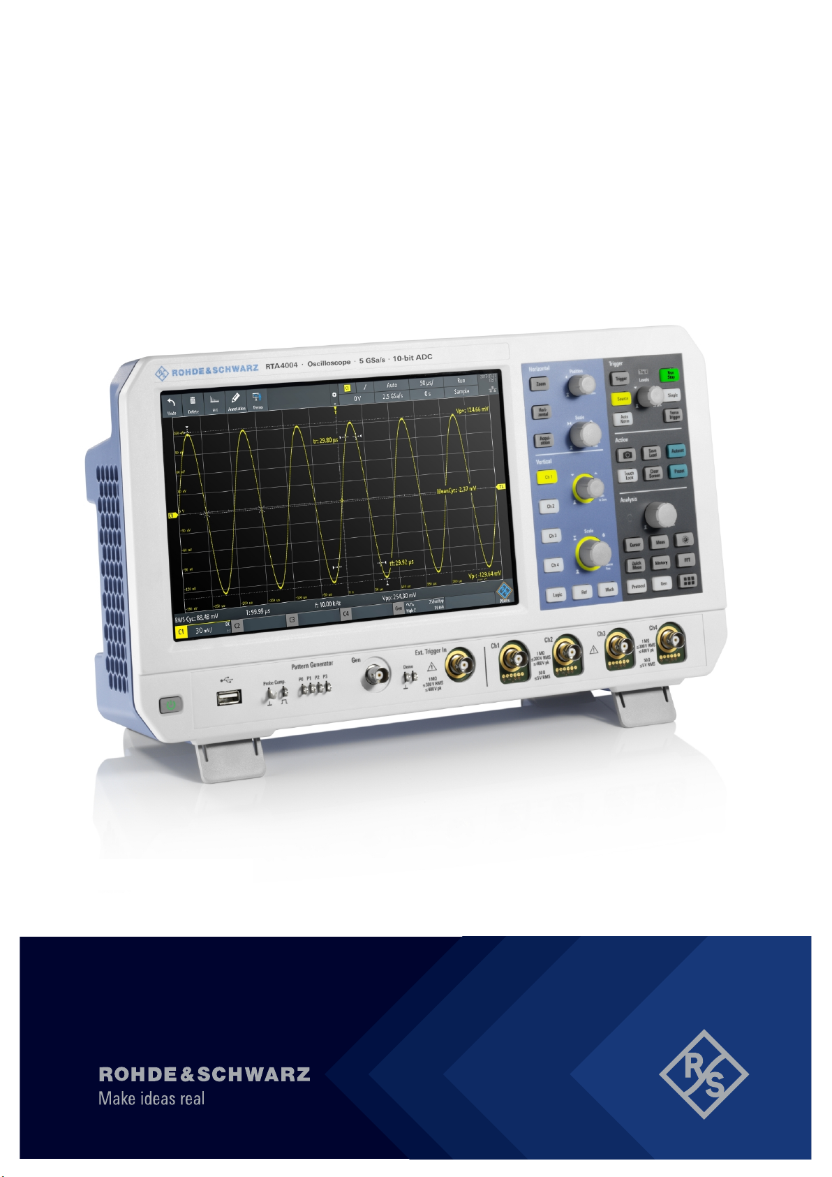
R&S®RTA4000
Oscilloscope
User Manual
(=SÜð2)
1335789802
Version 09

This manual describes the following R&S®RTA4000 models with firmware version 1.7xx:
●
R&S®RTA4004 (1335.7700K04)
In addition to the base unit, the following options are described:
●
R&S®RTA-K1, I²C/SPI trigger and decode
●
R&S®RTA-K2, UART/RS232 trigger and decode
●
R&S®RTA-K3, CAN/LIN trigger and decode
●
R&S®RTA-K5, I²S (audio) trigger and decode
●
R&S®RTA-K6, MIL.1553 trigger and decode
●
R&S®RTA-K7, ARINC 429 trigger and decode
●
R&S®RTA-K18, Spectrum analysis (replaced by K37)
●
R&S®RTA-K31, Power analysis
●
R&S®RTA-K36, Bode plot analysis
●
R&S®RTA-K37, Spectrum analysis
●
R&S®RTA-B1, Mixed signal option
●
R&S®RTA-B6, Arbitrary waveform and pattern generator
For order numbers of the options and bundlles, refer to the data sheet.
© 2022 Rohde & Schwarz GmbH & Co. KG
Muehldorfstr. 15, 81671 Muenchen, Germany
Phone: +49 89 41 29 - 0
Email: info@rohde-schwarz.com
Internet: www.rohde-schwarz.com
Subject to change – data without tolerance limits is not binding.
R&S® is a registered trademark of Rohde & Schwarz GmbH & Co. KG.
Trade names are trademarks of the owners.
1335.7898.02 | Version 09 | R&S®RTA4000
Throughout this manual, products from Rohde & Schwarz are indicated without the ® symbol, e.g. R&S®RTA4000 is indicated as
R&S RTA4000.

R&S®RTA4000
1.1 Safety instructions......................................................................................................17
1.2 Labels on the product.................................................................................................22
1.3 Warning messages in the documentation................................................................ 22
1.4 Where to find key documents on Rohde & Schwarz............................................... 23
1.5 Korea certification class A......................................................................................... 23
2.1 Documentation overview............................................................................................24
2.1.1 Manuals and instrument help........................................................................................ 24
2.1.2 Data sheet and brochure...............................................................................................25
Contents
Contents
1 Safety and regulatory information......................................................17
2 Preface.................................................................................................. 24
2.1.3 Calibration certificate.....................................................................................................25
2.1.4 Release notes and open source acknowledgment....................................................... 25
2.2 Conventions used in the documentation..................................................................25
2.2.1 Typographical conventions............................................................................................25
2.2.2 Conventions for procedure descriptions........................................................................26
2.2.3 Notes on screenshots................................................................................................... 26
3 Getting started......................................................................................27
3.1 Preparing for use........................................................................................................ 27
3.1.1 Lifting and carrying........................................................................................................27
3.1.2 Unpacking and checking............................................................................................... 27
3.1.3 Choosing the operating site.......................................................................................... 27
3.1.4 Setting up the product................................................................................................... 28
3.1.5 Considerations for test setup........................................................................................ 29
3.1.6 Connecting to power..................................................................................................... 30
3.2 Instrument tour............................................................................................................31
3.2.1 Front view......................................................................................................................31
3.2.2 Side view.......................................................................................................................33
3.2.3 Rear view...................................................................................................................... 33
4 Operating basics..................................................................................35
4.1 Display overview......................................................................................................... 35
3User Manual 1335.7898.02 ─ 09

R&S®RTA4000
4.2 Selecting the application............................................................................................36
4.3 Using the touchscreen............................................................................................... 36
4.3.1 Accessing functionality using the main menu............................................................... 36
4.3.2 Accessing functionality using shortcuts.........................................................................38
4.3.3 Entering data.................................................................................................................38
4.3.4 Using gestures.............................................................................................................. 39
4.4 Front panel keys..........................................................................................................40
4.4.1 Action controls...............................................................................................................40
4.4.2 Analysis controls........................................................................................................... 41
4.5 Using the toolbar.........................................................................................................42
4.6 Quick access............................................................................................................... 43
4.7 Menu history................................................................................................................44
4.8 Getting help................................................................................................................. 45
Contents
5 Waveform setup................................................................................... 46
5.1 Connecting probes and displaying a signal.............................................................46
5.2 Horizontal setup.......................................................................................................... 47
5.2.1 HORIZONTAL controls..................................................................................................49
5.2.2 Shortcuts for horizontal settings....................................................................................50
5.2.3 Horizontal settings.........................................................................................................50
5.3 Vertical setup...............................................................................................................51
5.3.1 VERTICAL controls....................................................................................................... 52
5.3.2 Short menu for analog channels................................................................................... 54
5.3.3 Vertical settings.............................................................................................................54
5.3.4 Threshold settings.........................................................................................................59
5.3.5 Label settings................................................................................................................ 60
5.4 Probes.......................................................................................................................... 61
5.4.1 Adjusting passive probes.............................................................................................. 61
5.4.2 Probe settings for probes with BNC connector............................................................. 62
5.4.3 Probe settings for probes with Rohde & Schwarz interface.......................................... 63
5.5 Acquisition setup........................................................................................................ 72
5.5.1 Shortcuts for acquisition settings.................................................................................. 73
5.5.2 Acquisition settings....................................................................................................... 73
6 Trigger...................................................................................................77
4User Manual 1335.7898.02 ─ 09

R&S®RTA4000
6.1 Trigger controls...........................................................................................................78
6.2 Shortcuts for trigger settings.................................................................................... 79
6.3 General trigger settings..............................................................................................80
6.4 Edge trigger................................................................................................................. 82
6.5 Edge A/B trigger..........................................................................................................84
6.6 Width trigger................................................................................................................85
6.7 Video trigger................................................................................................................ 88
6.8 Pattern trigger............................................................................................................. 90
6.9 Runt trigger..................................................................................................................93
6.10 Rise time trigger..........................................................................................................94
6.11 Timeout trigger............................................................................................................ 96
6.12 Actions on trigger....................................................................................................... 98
Contents
7 Waveform analysis.............................................................................101
7.1 Zoom.......................................................................................................................... 101
7.1.1 Zooming in.................................................................................................................. 101
7.1.2 Modifying the zoom..................................................................................................... 103
7.1.3 Zoom settings..............................................................................................................104
7.2 Mathematics.............................................................................................................. 105
7.2.1 Short menu for math waveforms................................................................................. 105
7.2.2 Configuring math waveforms...................................................................................... 106
7.2.3 Settings for math waveforms.......................................................................................106
7.2.4 Mathematic functions.................................................................................................. 107
7.2.5 Filters...........................................................................................................................110
7.2.6 Tracks..........................................................................................................................110
7.2.7 Saving and loading formularies................................................................................... 116
7.3 Reference waveforms............................................................................................... 116
7.3.1 Using references......................................................................................................... 117
7.3.2 Settings for reference waveforms................................................................................118
7.4 History and segmented memory ............................................................................ 121
7.4.1 Segmented memory....................................................................................................121
7.4.2 Activating the history................................................................................................... 122
7.4.3 History settings............................................................................................................123
7.4.4 Segment table and history player................................................................................124
5User Manual 1335.7898.02 ─ 09

R&S®RTA4000
7.4.5 Exporting history data................................................................................................. 127
7.5 Search........................................................................................................................ 130
7.5.1 Search conditions and results..................................................................................... 130
7.5.2 General search settings.............................................................................................. 133
7.5.3 Edge search................................................................................................................ 135
7.5.4 Width search............................................................................................................... 136
7.5.5 Peak search................................................................................................................ 137
7.5.6 Rise/fall time search....................................................................................................137
7.5.7 Runt setup...................................................................................................................139
7.5.8 Data2Clock..................................................................................................................140
7.5.9 Pattern search.............................................................................................................142
7.5.10 Window search............................................................................................................144
Contents
8 Measurements....................................................................................146
8.1 Quick measurements................................................................................................146
8.2 Automatic measurements........................................................................................ 147
8.2.1 Measurement results...................................................................................................147
8.2.2 Measurement types.....................................................................................................150
8.2.3 Settings for automatic measurements.........................................................................154
8.2.4 Delay setup................................................................................................................. 157
8.3 Cursor measurements.............................................................................................. 159
8.3.1 Cursor settings............................................................................................................ 161
9 Applications........................................................................................165
9.1 Mask testing.............................................................................................................. 165
9.1.1 About masks and mask testing................................................................................... 165
9.1.2 Using masks................................................................................................................166
9.1.3 Mask window...............................................................................................................169
9.1.4 Mask menu..................................................................................................................170
9.2 FFT analysis.............................................................................................................. 173
9.2.1 FFT display................................................................................................................. 173
9.2.2 Performing FFT analysis............................................................................................. 175
9.2.3 FFT setup....................................................................................................................175
9.3 Spectrum analysis and spectrogram (option R&S RTA-K18)............................... 181
9.3.1 FFT menu with spectrum analysis.............................................................................. 181
6User Manual 1335.7898.02 ─ 09

R&S®RTA4000
9.3.2 Spectrogram................................................................................................................183
9.3.3 Peak list and markers..................................................................................................185
9.3.4 Display settings for spectrum and spectrogram.......................................................... 190
9.4 Spectrum analysis and spectrogram (option R&S RTA-K37)............................... 191
9.4.1 FFT menu with spectrum analysis.............................................................................. 192
9.4.2 Spectrogram................................................................................................................193
9.4.3 Peak list and markers..................................................................................................195
9.4.4 Display settings for spectrum and spectrogram.......................................................... 200
9.5 XY-Diagram................................................................................................................201
9.6 Digital voltmeter........................................................................................................ 203
9.6.1 Using the meter...........................................................................................................204
9.6.2 Meter settings..............................................................................................................204
9.7 Trigger counter..........................................................................................................205
Contents
9.8 Bode plot (option R&S RTA-K36).............................................................................206
9.8.1 About the bode plot..................................................................................................... 207
9.8.2 Using a bode plot........................................................................................................ 208
9.8.3 Bode plot window controls.......................................................................................... 210
9.8.4 Bode plot settings........................................................................................................212
10 Documenting results......................................................................... 215
10.1 Saving and loading instrument settings.................................................................216
10.2 Saving waveform data.............................................................................................. 217
10.2.1 Waveform export settings............................................................................................218
10.2.2 Waveform file formats................................................................................................. 219
10.3 Annotations............................................................................................................... 221
10.4 Screenshots...............................................................................................................222
10.4.1 Screenshot settings.....................................................................................................223
10.5 Quick save with onetouch........................................................................................224
10.6 Export and import..................................................................................................... 225
11 General instrument setup..................................................................228
11.1 Instrument settings...................................................................................................228
11.2 Display settings.........................................................................................................231
11.3 Reset.......................................................................................................................... 234
11.4 Locking the touchscreen..........................................................................................235
7User Manual 1335.7898.02 ─ 09

R&S®RTA4000
11.5 Performing a self-alignment.....................................................................................235
11.6 Setting the date, time and language........................................................................236
11.7 Options.......................................................................................................................238
11.7.1 Activating options........................................................................................................ 238
11.8 Updating the firmware.............................................................................................. 239
12 Network connections and remote operation................................... 240
12.1 LAN connection.........................................................................................................240
12.1.1 LAN settings................................................................................................................240
12.2 USB connection........................................................................................................ 243
12.2.1 USB TMC.................................................................................................................... 243
12.2.2 USB VCP.................................................................................................................... 244
12.2.3 USB MTP.................................................................................................................... 244
Contents
12.3 Remote access using a web browser..................................................................... 244
12.3.1 Accessing the instrument using a web browser.......................................................... 244
12.3.2 Instrument home......................................................................................................... 245
12.3.3 Screenshot.................................................................................................................. 245
12.3.4 SCPI device control.....................................................................................................246
12.3.5 Save/load.................................................................................................................... 247
12.3.6 Network settings..........................................................................................................248
12.3.7 Change password....................................................................................................... 249
12.3.8 Livescreen...................................................................................................................249
12.3.9 Remote front panel......................................................................................................249
13 Serial bus analysis.............................................................................250
13.1 Basics of protocol analysis......................................................................................250
13.1.1 Protocol - common settings.........................................................................................251
13.1.2 Displaying decode results........................................................................................... 253
13.1.3 Bus table: decode results............................................................................................254
13.1.4 Bus labels....................................................................................................................256
13.1.5 Label list...................................................................................................................... 257
13.2 SPI bus (option R&S RTA-K1).................................................................................. 260
13.2.1 The SPI protocol......................................................................................................... 260
13.2.2 SPI configuration.........................................................................................................261
13.2.3 SPI trigger................................................................................................................... 264
8User Manual 1335.7898.02 ─ 09

R&S®RTA4000
13.2.4 SPI decode results...................................................................................................... 267
13.3 I²C (option R&S RTA-K1)...........................................................................................268
13.3.1 The I²C protocol.......................................................................................................... 269
13.3.2 I²C configuration..........................................................................................................270
13.3.3 I²C trigger.................................................................................................................... 272
13.3.4 I²C decode results....................................................................................................... 274
13.3.5 I²C label list................................................................................................................. 276
13.4 UART / RS232 (option R&S RTA-K2)....................................................................... 277
13.4.1 The UART / RS232 interface.......................................................................................277
13.4.2 UART configuration.....................................................................................................278
13.4.3 UART trigger............................................................................................................... 281
13.4.4 UART decode results.................................................................................................. 283
13.5 CAN (option R&S RTA-K3)........................................................................................284
Contents
13.5.1 The CAN protocol........................................................................................................285
13.5.2 CAN configuration....................................................................................................... 286
13.5.3 CAN trigger................................................................................................................. 288
13.5.4 CAN decode results.................................................................................................... 292
13.5.5 Search on decoded CAN data.................................................................................... 294
13.5.6 CAN label list...............................................................................................................296
13.6 LIN (option R&S RTA-K3)..........................................................................................298
13.6.1 The LIN protocol..........................................................................................................298
13.6.2 LIN configuration......................................................................................................... 300
13.6.3 LIN trigger................................................................................................................... 302
13.6.4 LIN decode results...................................................................................................... 305
13.6.5 Search on decoded LIN data...................................................................................... 306
13.6.6 LIN label list.................................................................................................................309
13.7 Audio signals (option R&S RTA-K5)........................................................................ 311
13.7.1 Audio protocols............................................................................................................311
13.7.2 Audio configuration..................................................................................................... 313
13.7.3 Setup of audio variants............................................................................................... 316
13.7.4 Audio trigger................................................................................................................318
13.7.5 Audio decode results...................................................................................................320
13.8 MIL-STD-1553 (option R&S RTA-K6)........................................................................320
9User Manual 1335.7898.02 ─ 09

R&S®RTA4000
13.8.1 The MIL-STD-1553..................................................................................................... 321
13.8.2 MIL-STD-1553 configuration....................................................................................... 323
13.8.3 MIL-STD-1553 trigger................................................................................................. 325
13.8.4 MIL-STD-1553 decode results.................................................................................... 330
13.8.5 MIL-STD-1553 label list...............................................................................................331
13.9 ARINC 429 (option R&S RTA-K7)............................................................................. 331
13.9.1 ARINC 429 basics.......................................................................................................331
13.9.2 ARINC 429 configuration............................................................................................ 332
13.9.3 ARINC 429 trigger.......................................................................................................334
13.9.4 ARINC 429 decode results..........................................................................................338
13.9.5 Search on decoded ARINC 429 data..........................................................................339
13.9.6 ARINC 429 label list.................................................................................................... 341
Contents
14 Power analysis (option R&S RTA-K31)............................................ 343
14.1 Probe adjustment......................................................................................................343
14.1.1 Deskewing the probes.................................................................................................343
14.1.2 Probe settings for power measurements.................................................................... 344
14.2 Report settings..........................................................................................................344
14.3 Statistic menu settings.............................................................................................345
14.4 Input power measurements..................................................................................... 346
14.4.1 Quality......................................................................................................................... 346
14.4.2 Consumption............................................................................................................... 350
14.4.3 Harmonics................................................................................................................... 353
14.4.4 Inrush current.............................................................................................................. 356
14.5 Output power measurements.................................................................................. 359
14.5.1 Ripple.......................................................................................................................... 359
14.5.2 Spectrum.....................................................................................................................362
14.5.3 Transient response......................................................................................................365
14.6 Switching power measurements............................................................................. 367
14.6.1 Slew rate..................................................................................................................... 368
14.6.2 Modulation...................................................................................................................370
14.6.3 Dynamic on resistance................................................................................................373
14.7 Power path power measurements...........................................................................375
14.7.1 Efficiency.....................................................................................................................375
10User Manual 1335.7898.02 ─ 09

R&S®RTA4000
14.7.2 Switching loss............................................................................................................. 378
14.7.3 Turn ON/OFF time.......................................................................................................381
14.7.4 Safe operating area (S.O.A.).......................................................................................384
15 Logic analyzer (option R&S RTA-B1, MSO)..................................... 392
15.1 Short menu for logic channels................................................................................ 392
15.2 Logic analyzer settings............................................................................................ 394
15.3 Triggering on logic channels................................................................................... 396
15.4 Analyzing logic channels......................................................................................... 396
15.5 Parallel buses............................................................................................................ 397
15.5.1 Parallel bus configuration............................................................................................397
15.5.2 Decode results............................................................................................................ 399
16 Signal generation (option R&S RTA-B6).......................................... 401
Contents
16.1 Function generator................................................................................................... 401
16.1.1 Using the function generator....................................................................................... 401
16.1.2 Basic settings of the function generator...................................................................... 404
16.1.3 Sweep settings............................................................................................................407
16.1.4 Modulation settings..................................................................................................... 408
16.1.5 Burst settings.............................................................................................................. 410
16.1.6 Arbitrary setup settings................................................................................................411
16.2 Pattern generator...................................................................................................... 413
16.2.1 Pattern selection......................................................................................................... 413
16.2.2 Settings for square wave pattern................................................................................ 414
16.2.3 Settings for counter pattern.........................................................................................415
16.2.4 Settings for arbitrary pattern........................................................................................416
16.2.5 Settings for manual pattern......................................................................................... 419
16.2.6 Settings for serial buses..............................................................................................419
16.2.7 Settings for PWM signals............................................................................................ 420
17 Remote control commands...............................................................423
17.1 Conventions used in command description.......................................................... 423
17.2 Programming examples........................................................................................... 424
17.2.1 Documenting results................................................................................................... 424
17.2.2 Firmware update......................................................................................................... 428
11User Manual 1335.7898.02 ─ 09

R&S®RTA4000
17.2.3 Search.........................................................................................................................429
17.2.4 Function generator...................................................................................................... 430
17.3 Common commands.................................................................................................430
17.4 Waveform setup........................................................................................................ 433
17.4.1 Automatic setup.......................................................................................................... 434
17.4.2 Starting and stopping acquisition................................................................................ 434
17.4.3 Vertical settings...........................................................................................................435
17.4.4 Passive probes............................................................................................................442
17.4.5 Active probes.............................................................................................................. 443
17.4.6 R&S ProbeMeter......................................................................................................... 450
17.4.7 Horizontal settings.......................................................................................................452
17.4.8 Acquisition settings..................................................................................................... 454
17.4.9 Waveform data............................................................................................................459
Contents
17.5 Trigger........................................................................................................................460
17.5.1 General trigger settings...............................................................................................460
17.5.2 Edge trigger.................................................................................................................462
17.5.3 Edge A/B trigger..........................................................................................................464
17.5.4 Width trigger................................................................................................................465
17.5.5 Video/TV trigger.......................................................................................................... 467
17.5.6 Pattern trigger............................................................................................................. 468
17.5.7 Runt trigger................................................................................................................. 471
17.5.8 Risetime trigger........................................................................................................... 472
17.5.9 Timeout trigger............................................................................................................ 474
17.5.10 Serial bus.................................................................................................................... 475
17.5.11 Actions on trigger........................................................................................................ 475
17.6 Waveform analysis....................................................................................................477
17.6.1 Zoom........................................................................................................................... 478
17.6.2 Mathematics................................................................................................................479
17.6.3 Reference waveforms................................................................................................. 483
17.6.4 Search.........................................................................................................................487
17.6.5 History ........................................................................................................................ 503
17.7 Measurements........................................................................................................... 514
17.7.1 Quick measurements.................................................................................................. 514
12User Manual 1335.7898.02 ─ 09

R&S®RTA4000
17.7.2 Automatic measurements........................................................................................... 515
17.7.3 Cursor measurements.................................................................................................529
17.8 Applications...............................................................................................................536
17.8.1 General....................................................................................................................... 536
17.8.2 Mask testing................................................................................................................ 536
17.8.3 FFT analysis................................................................................................................542
17.8.4 Spectrum analysis and spectrogram (options R&S RTA-K18/K37).............................549
17.8.5 XY-Waveforms.............................................................................................................557
17.8.6 Digital voltmeter.......................................................................................................... 558
17.8.7 Trigger counter............................................................................................................560
17.8.8 Bode plot (option R&S RTA-K36)................................................................................561
17.9 Documenting results................................................................................................ 569
17.9.1 Transfer of waveform data.......................................................................................... 569
Contents
17.9.2 Waveform data export to file....................................................................................... 581
17.9.3 Screenshots................................................................................................................ 582
17.9.4 Instrument settings: mass MEMomory subsystem......................................................584
17.10 General instrument setup.........................................................................................591
17.10.1 Display settings........................................................................................................... 591
17.10.2 System settings...........................................................................................................596
17.10.3 LAN settings................................................................................................................599
17.10.4 USB settings............................................................................................................... 601
17.10.5 Trigger out...................................................................................................................602
17.10.6 Firmware update......................................................................................................... 603
17.11 Serial bus analysis....................................................................................................604
17.11.1 General....................................................................................................................... 604
17.11.2 SPI (option R&S RTA-K1)........................................................................................... 606
17.11.3 I²C (option R&S RTA-K1)............................................................................................ 619
17.11.4 UART (option R&S RTA-K2)....................................................................................... 629
17.11.5 CAN (option R&S RTA-K3)..........................................................................................638
17.11.6 LIN (option R&S RTA-K3)............................................................................................654
17.11.7 Audio (option R&S RTA-K5)........................................................................................ 667
17.11.8 MIL-1553 (option R&S RTA-K6).................................................................................. 679
17.11.9 ARINC 429 (option R&S RTA-K7)............................................................................... 701
13User Manual 1335.7898.02 ─ 09

R&S®RTA4000
17.12 Power analysis (option R&S RTA-K31)................................................................... 714
17.12.1 General....................................................................................................................... 714
17.12.2 Probe adjustment........................................................................................................ 716
17.12.3 Report......................................................................................................................... 717
17.12.4 Consumption............................................................................................................... 718
17.12.5 Dynamic ON resistance.............................................................................................. 720
17.12.6 Power efficiency.......................................................................................................... 721
17.12.7 Current harmonic........................................................................................................ 723
17.12.8 Inrush current.............................................................................................................. 729
17.12.9 Modulation analysis.....................................................................................................730
17.12.10 Turn on/off...................................................................................................................734
17.12.11 Quality......................................................................................................................... 735
17.12.12 Ripple.......................................................................................................................... 739
Contents
17.12.13 Slew rate..................................................................................................................... 744
17.12.14 S.O.A...........................................................................................................................750
17.12.15 Spectrum.....................................................................................................................758
17.12.16 Switching.....................................................................................................................761
17.12.17 Transient response......................................................................................................765
17.13 Mixed signal option (option R&S RTA-B1)..............................................................767
17.13.1 Logic channels............................................................................................................ 767
17.13.2 Parallel buses..............................................................................................................774
17.14 Signal generation (option R&S RTA-B6)................................................................. 779
17.14.1 Function generator...................................................................................................... 779
17.14.2 Pattern generator........................................................................................................ 787
17.15 Status reporting........................................................................................................ 795
17.15.1 STATus:OPERation register........................................................................................795
17.15.2 STATus:QUEStionable registers................................................................................. 797
18 Maintenance and support..................................................................801
18.1 Cleaning..................................................................................................................... 801
18.2 Changing fuses......................................................................................................... 801
18.3 Contacting customer support..................................................................................801
18.4 Data security..............................................................................................................802
18.5 Storage.......................................................................................................................802
14User Manual 1335.7898.02 ─ 09

R&S®RTA4000
18.6 Disposal..................................................................................................................... 802
A Remote control basics.......................................................................804
A.1 SCPI command structure......................................................................................... 804
A.1.1 Syntax for common commands...................................................................................804
A.1.2 Syntax for instrument-specific commands.................................................................. 805
A.1.3 SCPI parameters.........................................................................................................806
A.1.4 Overview of syntax elements...................................................................................... 809
A.1.5 Structure of a command line....................................................................................... 810
A.1.6 Responses to queries..................................................................................................811
A.2 Command sequence and synchronization............................................................. 812
A.2.1 Preventing overlapping execution............................................................................... 812
Contents
Annex.................................................................................................. 804
A.3 Messages................................................................................................................... 814
A.3.1 Instrument messages..................................................................................................814
A.3.2 LAN interface messages............................................................................................. 815
B Remote control - status reporting system.......................................816
B.1 Structure of a SCPI status register..........................................................................816
B.2 Hierarchy of status registers................................................................................... 817
B.3 Contents of the status registers.............................................................................. 819
B.3.1 Status byte (STB) and service request enable register (SRE)....................................819
B.3.2 Event status register (ESR) and event status enable register (ESE)..........................820
B.3.3 STATus:OPERation register........................................................................................821
B.3.4 STATus:QUEStionable register................................................................................... 821
B.4 Application of the status reporting system............................................................ 825
B.4.1 Service request........................................................................................................... 825
B.4.2 Serial poll.................................................................................................................... 825
B.4.3 Query of an instrument status..................................................................................... 826
B.4.4 Error queue................................................................................................................. 826
B.5 Reset values of the status reporting system..........................................................827
List of commands.............................................................................. 828
15User Manual 1335.7898.02 ─ 09

R&S®RTA4000
Contents
16User Manual 1335.7898.02 ─ 09

R&S®RTA4000
1 Safety and regulatory information
Safety and regulatory information
Safety instructions
The product documentation helps you to use the product safely and efficiently. Follow
the instructions provided here and in the Chapter 1.1, "Safety instructions",
on page 17.
Intended use
The R&S RTA4000 oscilloscope is designed for measurements on circuits that are only
indirectly connected to the mains or not connected at all. It is not rated for any measurement category.
The product is intended for the development, production and verification of electronic
components and devices in industrial, administrative, and laboratory environments.
Use the product only for its designated purpose. Observe the operating conditions and
performance limits stated in the data sheet.
Where do I find safety information?
Safety information is part of the product documentation. It warns you of potential dangers and gives instructions on how to prevent personal injury or damage caused by
dangerous situations. Safety information is provided as follows:
●
In Chapter 1.1, "Safety instructions", on page 17. The same information is provided in many languages as printed "Safety Instructions". The printed "Safety
Instructions" are delivered with the product.
●
Throughout the documentation, safety instructions are provided when you need to
take care during setup or operation.
1.1 Safety instructions
Products from the Rohde & Schwarz group of companies are manufactured according
to the highest technical standards. To use the products safely, follow the instructions
provided here and in the product documentation. Keep the product documentation
nearby and offer it to other users.
Use the product only for its intended use and within its performance limits. Intended
use and limits are described in the product documentation such as the data sheet,
manuals and the printed "Safety Instructions". If you are unsure about the appropriate
use, contact Rohde & Schwarz customer service.
Using the product requires specialists or specially trained personnel. These users also
need sound knowledge of at least one of the languages in which the user interfaces
and the product documentation are available.
Never open the casing of the product. Only service personnel authorized by
Rohde & Schwarz are allowed to repair the product. If any part of the product is damaged or broken, stop using the product. Contact Rohde & Schwarz customer service at
http://www.customersupport.rohde-schwarz.com.
17User Manual 1335.7898.02 ─ 09

R&S®RTA4000
Safety and regulatory information
Safety instructions
In these safety instructions, the term "product" covers instruments (oscilloscopes),
probes and their accessories.
Lifting and carrying the instrument
Check the data sheet for the maximum weight of the instrument. A single person can
only carry a maximum of 18 kg safely depending on age, gender and physical condition. If your instrument is heavier than 18 kg, do not move or carry it by yourself.
Use the instrument handles to move or carry the instrument. Do not use the mounted
accessories instead of the handles. Accessories are not designed to carry the weight
of the instrument.
To move the instrument safely, you can use lifting or transporting equipment such as lift
trucks and forklifts. Follow the instructions provided by the equipment manufacturer.
Choosing the operating site
Only use the product indoors. The product casing is not waterproof. Water that enters
can electrically connect the casing with live parts, which can lead to electric shock,
serious personal injury or death if you touch the casing. If Rohde & Schwarz provides
accessories designed for your product, e.g. a carrying bag, you can use the product
outdoors.
You can operate the product up to the altitude specified in the data sheet. The lowest
specified altitude for a product of the measurement setup defines the altitude for the
complete setup.
The product is suitable for pollution degree 2 environments where nonconductive contamination can occur. For more information on environmental conditions such as ambient temperature and humidity, see the data sheet.
Setting up the product
Always place the product on a stable, flat and level surface with the bottom of the product facing down. If the product is designed for different positions, secure the product so
that it cannot fall over.
If the product has foldable feet, always fold the feet completely in or out to ensure stability. The feet can collapse if they are not folded out completely or if the product is
moved without lifting it. The foldable feet are designed to carry the weight of the product, but not an extra load.
If stacking is possible, keep in mind that a stack of products can fall over and cause
injury.
If you mount products in a rack, ensure that the rack has sufficient load capacity and
stability. Observe the specifications of the rack manufacturer. Always install the products from the bottom shelf to the top shelf so that the rack stands securely. Secure the
product so that it cannot fall off the rack.
Connecting to power and grounding
The mains power supply input of the instrument complies with overvoltage category II.
It has to be connected to a fixed installation used to supply energy-consuming equip-
18User Manual 1335.7898.02 ─ 09

R&S®RTA4000
Safety and regulatory information
Safety instructions
ment such as household appliances and similar loads. Be aware that electrically powered products have risks, such as electric shock, fire, personal injury or even death.
Take the following measures for your safety:
●
Do not use an isolating transformer to connect the instrument to the mains power
supply.
●
Before switching on the product, ensure that the voltage and frequency indicated
on the product match the available power source. If the power adapter does not
adjust automatically, set the correct value and check the rating of the fuse.
●
Only use the power cable delivered with the product. It complies with country-specific safety requirements. Only insert the plug into an outlet with protective conductor terminal.
●
If a product has an exchangeable fuse, its type and characteristics are indicated
next to the fuse holder. Before changing the fuse, switch off the instrument and disconnect it from the power source. How to change the fuse is described in the product documentation.
●
Only use intact cables and route them carefully so that they cannot be damaged.
Check the power cables regularly to ensure that they are undamaged. Also ensure
that nobody can trip over loose cables.
●
If the product needs an external power supply, use the power supply that is delivered with the product or that is recommended in the product documentation or a
power supply that conforms to the country-specific regulations.
●
Ensure that you can disconnect the product from the power source at any time.
Pull the power plug to disconnect the product. The power plug must be easily
accessible. If the product is integrated into a system that does not meet these
requirements, provide an easily accessible circuit breaker at the system level.
Performing measurements
Take the following measures for your safety:
●
To ascertain voltage-free state, use an appropriate voltage tester. Any measurement setup including an oscilloscope is not suitable for this purpose.
●
The maximum input voltage on channel inputs and the external trigger input must
not exceed the value specified in the data sheet.
●
Observe all voltage and current ratings of the instrument, the probes, and the
accessories. Limits and ratings are marked on the products and listed in the data
sheets.
Consider that the rated voltage depends on the frequency. The voltage limitation
curves or values are provided in the data sheet. Do not exceed the maximum measurement voltage from the probe tip to the probe reference lead.
●
Never cause any short circuits when measuring sources with high output currents.
●
Use only probes and accessories that comply with the measurement category
(CAT) of your measurement task. The measurement category of the products is
defined in the data sheet. If you use other than Rohde & Schwarz accessories,
make sure that they are suitable for the instrument and the measurement task.
●
Set the correct attenuation factor on the instrument according to the probe being
used. Otherwise, the measurement results do not reflect the actual voltage level,
and you might misjudge the actual risk.
19User Manual 1335.7898.02 ─ 09

R&S®RTA4000
Safety and regulatory information
Safety instructions
●
When working with high voltages and current probes, observe the additional operating conditions specified in this safety instructions.
●
The probe pins are extremely pointed and can easily penetrate clothes and the
skin. Handle the probe pins with great care. To exchange a probe pin, use tweezers or pliers to avoid injuries. When transporting the accessories, always use the
box supplied with the probe.
●
Prevent the probe from receiving mechanical shock. Avoid putting excessive strain
on the probe cable or exposing it to sharp bends. Touching a broken cable during
measurements can cause injuries.
●
Set up all probe connections to the instrument before applying power.
Working with hazardous voltages
Voltages higher than 30 V RMS, or 42 V peak, or 60 V DC are regarded as hazardous
contact voltages. Direct contact with them can cause serious injuries.
Make sure that only electrically skilled persons use the products for measurements on
hazardous contact voltages. These working conditions require special education and
experience to perceive risks and to avoid hazards which electricity can create.
When working with hazardous contact voltages, use protective measures to preclude
direct contact with the measurement setup:
●
Do not touch exposed connections and components when power is applied.
●
Switch off the test circuit while connecting and disconnecting probe leads.
●
Use only insulated voltage probes, test leads and adapters.
●
Make sure that the input leads fulfill the safety requirements for your measurement.
The delivered input leads might have a jacket wear indicator that indicates a worn
jacket by different jacket color. In this case, do not use the input lead. Replace it
with a new one.
●
Do not use 4 mm banana plugs without protection against contact.
Working with current probes
When working with current probes, you can measure high-frequency currents or currents that contain high-frequency components.
●
Switch off the test circuit while connecting the probe.
●
Do not attach the clamp to bare unisolated conductors. To avoid injury from a short
circuit, measure at a location on an insulated wire where the insulation is sufficient
for the circuit voltage.
●
Connect the probe only to the secondary side of a breaker. With this measure, you
avoid injury, if a short circuit occurs.
●
The following effects can cause burns and fire or damage to the measurement site:
– Eddy current loss can cause heating of the sensor head.
– Dielectric heating can cause heating of cord insulation and other materials.
20User Manual 1335.7898.02 ─ 09

R&S®RTA4000
Safety and regulatory information
Safety instructions
Measurement categories
IEC 61010-2-030 defines measurement categories that rate instruments on their ability
to resist short transient overvoltages that occur in addition to the working voltage. Use
the measurement setup only in electrical environments for which they are rated.
●
0 - Instruments without rated measurement category
For measurements performed on circuits not directly connected to mains, for example, electronics, circuits powered by batteries, and specially protected secondary
circuits. This measurement category is also known as CAT I.
●
CAT II:
For measurements performed on circuits directly connected to the low-voltage
installation by a standard socket outlet, for example, household appliances and
portable tools.
●
CAT III:
For measurements performed in the building installation, such as junction boxes,
circuit breakers, distribution boards, and equipment with permanent connection to
the fixed installation.
●
CAT IV:
For measurements performed at the source of the low-voltage installation, such as
electricity meters and primary overcurrent protection devices.
Cleaning the product
Use a dry, lint-free cloth to clean the product. When cleaning, keep in mind that the
casing is not waterproof. Do not use liquid cleaning agents.
Meaning of safety labels
Safety labels on the product warn against potential hazards.
21User Manual 1335.7898.02 ─ 09

R&S®RTA4000
1.2 Labels on the product
Safety and regulatory information
Warning messages in the documentation
Potential hazard
Read the product documentation to avoid personal injury or product damage.
Electrical hazard
Indicates live parts. Risk of electric shock, fire, personal injury or even death.
Protective conductor terminal
Connect this terminal to a grounded external conductor or to protective ground. This protects
you against electric shock should an electric problem occur.
Labels on the casing inform about:
●
Personal safety, see "Meaning of safety labels" on page 21
●
Product and environment safety, see Table 1-1
●
Identification of the product
Table 1-1: Labels regarding product and environment safety
Chassis grounding terminal
Take care when handling electrostatic sensitive devices.
Labeling in line with EN 50419 for disposal of electrical and electronic equipment after the product has come to the end of its service life.
For more information, see "Disposing electrical and electronic equipment" on page 802.
1.3 Warning messages in the documentation
A warning message points out a risk or danger that you need to be aware of. The signal word indicates the severity of the safety hazard and how likely it will occur if you do
not follow the safety precautions.
WARNING
Potentially hazardous situation. Could result in death or serious injury if not avoided.
CAUTION
Potentially hazardous situation. Could result in minor or moderate injury if not avoided.
22User Manual 1335.7898.02 ─ 09

R&S®RTA4000
1.4 Where to find key documents on Rohde & Schwarz
Safety and regulatory information
Korea certification class A
NOTICE
Potential risks of damage. Could result in damage to the supported product or to other
property.
Certificates issued to Rohde & Schwarz that are relevant for your country are provided
at www.rohde-schwarz.com/key-documents, e.g. concerning:
●
Quality management
●
Environmental management
●
Information security management
●
Accreditations
1.5 Korea certification class A
이 기기는 업무용(A급) 전자파 적합기기로서 판매자 또는 사용자는 이 점을 주의하시기
바라며, 가정외의 지역에서 사용하는 것을 목적으로 합니다.
23User Manual 1335.7898.02 ─ 09

R&S®RTA4000
2 Preface
2.1 Documentation overview
2.1.1 Manuals and instrument help
Preface
Documentation overview
This section provides an overview of the R&S RTA4000 user documentation.
You find the manuals on the product page at:
www.rohde-schwarz.com/manual/rta4000
Getting started manual
Introduces the R&S RTA4000 and describes how to set up the product. A printed English version is included in the delivery.
User manual
Contains the description of all instrument modes and functions. It also provides an
introduction to remote control, a complete description of the remote control commands
with programming examples, and information on maintenance and instrument interfaces. Includes the contents of the getting started manual.
The online version of the user manual provides the complete contents for immediate
display on the internet.
Instrument help
The help offers quick, context-sensitive access to the functional description directly on
the instrument.
Safety instructions
Provides safety information in many languages. The printed document is delivered with
the product.
Instrument security procedures manual
Deals with security issues when working with the R&S RTA4000 in secure areas.
Service manual
Describes the performance test for checking the rated specifications, module replacement and repair, firmware update, troubleshooting and fault elimination, and contains
mechanical drawings and spare part lists. The service manual is available for registered users on the global Rohde & Schwarz information system (GLORIS, https://
gloris.rohde-schwarz.com).
24User Manual 1335.7898.02 ─ 09
R&S®RTA4000
2.1.2 Data sheet and brochure
2.1.3 Calibration certificate
2.1.4 Release notes and open source acknowledgment
Preface
Conventions used in the documentation
The data sheet contains the technical specifications of the R&S RTA4000. It also lists
the options with their order numbers and optional accessories. The brochure provides
an overview of the instrument and deals with the specific characteristics.
See www.rohde-schwarz.com/brochure-datasheet/rta4000
The document is available on https://gloris.rohde-schwarz.com/calcert. You need the
device ID of your instrument, which you can find on a label on the rear panel.
The release notes list new features, improvements and known issues of the current
firmware version, and describe the firmware installation. The open source acknowledgment document provides verbatim license texts of the used open source software. It
can also be read directly on the instrument.
See www.rohde-schwarz.com/firmware/rta4000. The open source acknowledgment
document can also be read directly on the instrument.
2.2 Conventions used in the documentation
2.2.1 Typographical conventions
The following text markers are used throughout this documentation:
Convention Description
"Graphical user interface elements"
[Keys] Key and knob names are enclosed by square brackets.
Filenames, commands,
program code
Input Input to be entered by the user is displayed in italics.
Links Links that you can click are displayed in blue font.
All names of graphical user interface elements on the screen, such as
dialog boxes, menus, options, buttons, and softkeys are enclosed by
quotation marks.
Filenames, commands, coding samples and screen output are distinguished by their font.
"References" References to other parts of the documentation are enclosed by quota-
tion marks.
25User Manual 1335.7898.02 ─ 09

R&S®RTA4000
2.2.2 Conventions for procedure descriptions
2.2.3 Notes on screenshots
Preface
Conventions used in the documentation
When operating the instrument, several alternative methods may be available to perform the same task. In this case, the procedure using the touchscreen is described.
Any elements that can be activated by touching can also be clicked using an additionally connected mouse. The alternative procedure using the keys on the instrument or
the on-screen keyboard is only described if it deviates from the standard operating procedures.
The term "select" may refer to any of the described methods, i.e. using a finger on the
touchscreen, a mouse pointer in the display, or a key on the instrument or on a keyboard.
When describing the functions of the product, we use sample screenshots. These
screenshots are meant to illustrate as many as possible of the provided functions and
possible interdependencies between parameters. The shown values may not represent
realistic usage scenarios.
The screenshots usually show a fully equipped product, that is: with all options installed. Thus, some functions shown in the screenshots may not be available in your particular product configuration.
26User Manual 1335.7898.02 ─ 09

R&S®RTA4000
3 Getting started
3.1 Preparing for use
3.1.1 Lifting and carrying
3.1.2 Unpacking and checking
Getting started
Preparing for use
Here, you can find basic information about setting up the instrument for the first time or
when changing the operating site.
See: "Lifting and carrying the instrument" on page 18.
1. Unpack the product carefully.
2. Retain the original packing material. Use it when transporting or shipping the product later.
3. Using the delivery notes, check the equipment for completeness.
4. Check the equipment for damage.
If the delivery is incomplete or equipment is damaged, contact Rohde & Schwarz.
Delivery contents
The delivery package contains the following items:
●
R&S RTA4000 oscilloscope
●
R&S RT-ZP10 probes (4x)
●
Country-specific power cable
●
Printed "Getting Started" manual
●
Printed Rohde & Schwarz Oscilloscopes and Accessories Safety Instructions (Multilingual) brochure
3.1.3 Choosing the operating site
Specific operating conditions ensure proper operation and avoid damage to the product and connected devices. For information on environmental conditions such as ambient temperature and humidity, see the data sheet.
See also "Choosing the operating site" on page 18.
27User Manual 1335.7898.02 ─ 09

R&S®RTA4000
3.1.4 Setting up the product
Getting started
Preparing for use
Electromagnetic compatibility classes
The electromagnetic compatibility (EMC) class indicates where you can operate the
product. The EMC class of the product is given in the data sheet.
●
Class B equipment is suitable for use in:
– Residential environments
– Environments that are directly connected to a low-voltage supply network that
supplies residential buildings
●
Class A equipment is intended for use in industrial environments. It can cause
radio disturbances in residential environments due to possible conducted and radiated disturbances. It is therefore not suitable for class B environments.
If class A equipment causes radio disturbances, take appropriate measures to
eliminate them.
When setting up the instrument, follow the safety instructions:
●
"Setting up the product" on page 18
●
"Intended use" on page 17
3.1.4.1 Placing the product on a bench top
For standalone operation, place the instrument on a horizontal bench with even, flat
surface. The instrument can be used in horizontal position, standing on its feet, or with
the support feet on the bottom extended.
To place the product on a bench top
1. Place the product on a stable, flat and level surface.
CAUTION! The top surface of the product is too small for stacking. If you stack
2.
another product on top of the product, the stack can fall over and cause injury.
If you want to save space, mount several products in a rack.
CAUTION! Foldable feet can collapse. See "Setting up the product" on page 18.
3.
Always fold the feet completely in or out. With folded-out feet, do not place any-
thing on top or underneath.
28User Manual 1335.7898.02 ─ 09

R&S®RTA4000
3.1.4.2 Mounting the product in a rack
Getting started
Preparing for use
NOTICE! Overheating can damage the product.
4.
Prevent overheating as follows:
● Keep a minimum distance of 10 cm between the fan openings of the product
and any object in the vicinity.
● Do not place the product next to heat-generating equipment such as radiators
or other products.
The instrument can be installed in a rack using a rack adapter kit. The order number is
given in the data sheet. The installation instructions are part of the adapter kit.
To prepare the rack
1. Observe the requirements and instructions in "Setting up the product" on page 18.
NOTICE! Insufficient airflow can cause overheating and damage the product.
2.
Design and implement an efficient ventilation concept for the rack.
To mount the R&S RTA4000 in a rack
1. Use an adapter kit that fits the dimensions of the R&S RTA4000 to prepare the
instrument for rack mounting. For information on the dimensions, see data sheet.
a) Order the rack adapter kit designed for the R&S RTA4000. For the order num-
ber, see data sheet.
b) Mount the adapter kit. Follow the assembly instructions provided with the
adapter kit.
2. Push the product onto the shelf until the rack brackets fit closely to the rack.
3. Tighten all screws at the rack brackets with a tightening torque of 1.2 Nm to secure
the product at the rack.
To unmount the product from a rack
1. Loosen the screws at the rack brackets.
2. Remove the product from the rack.
3. If placing the product on a bench top again, unmount the adapter kit from the product. Follow the instructions provided with the adapter kit.
3.1.5 Considerations for test setup
Observe safety instructions, see "Performing measurements" on page 19.
Cable selection and electromagnetic interference (EMI)
Electromagnetic interference (EMI) can affect the measurement results.
29User Manual 1335.7898.02 ─ 09

R&S®RTA4000
Getting started
Preparing for use
To suppress electromagnetic radiation during operation:
●
Use high-quality shielded cables, for example, double-shielded RF and LAN
cables.
●
Always terminate open cable ends.
●
Ensure that connected external devices comply with EMC regulations.
Measuring accessories
Use only probes and measuring accessories that comply with IEC 61010-031.
Signal input and output levels
Information on signal levels is provided in the data sheet. Keep the signal levels within
the specified ranges to avoid damage to the product and connected devices.
Preventing electrostatic discharge (ESD)
Electrostatic discharge is most likely to occur when you connect or disconnect a DUT.
NOTICE! Electrostatic discharge can damage the electronic components of the
►
product and the device under test (DUT).
Ground yourself to prevent electrostatic discharge damage:
a) Use a wrist strap and cord to connect yourself to ground.
b) Use a conductive floor mat and heel strap combination.
During operation, if the firmware observes a serious unexpected disturbance (e.g. due
to ESD), it resets some hardware components and initiates a new alignment to ensure
proper instrument functioning. Then it restores the user settings to the state before the
disturbance.
3.1.6 Connecting to power
For safety information, see "Connecting to power and grounding" on page 18.
The R&S RTA4000 can be used with different AC power voltages and adapts itself
automatically to it.
The nominal ranges are:
●
100 V to 240 V AC at 50 Hz to 60 Hz, with maximal 10% voltage fluctuation on line
●
1.6 A to 0.7 A
●
max. 160 W
1. Plug the AC power cable into the AC power connector on the rear panel of the
product. Only use the AC power cable delivered with the product.
2. Plug the AC power cable into a power outlet with ground contact.
The required ratings are listed next to the AC power connector and in the data
sheet.
30User Manual 1335.7898.02 ─ 09
 Loading...