

Page 1
®
R&S
NRP-Zxx
Power Sensors
Getting Started
(;ÚæF2)
1176882202
Version 04
Page 2

This manual gives an introduction to the Rohde & Schwarz NRP-Z sensors.
© 2021 Rohde & Schwarz GmbH & Co. KG
Mühldorfstr. 15, 81671 München, Germany
Phone: +49 89 41 29 - 0
Email: info@rohde-schwarz.com
Internet: www.rohde-schwarz.com
Subject to change – data without tolerance limits is not binding.
R&S® is a registered trademark of Rohde & Schwarz GmbH & Co. KG.
Trade names are trademarks of the owners.
1176.8822.02 | Version 04 | R&S®NRP-Zxx
Throughout this manual, products from Rohde & Schwarz are indicated without the ® symbol, for example
R&S®NRP2 is abbreviated as R&S NRP2.
Page 3

R&S®NRP-Zxx
Contents
1 Safety Information................................................................. 5
2 Documentation Overview......................................................6
2.1 Getting Started Manual.........................................................................6
2.2 User Manuals.........................................................................................6
2.3 Tutorials................................................................................................. 6
2.4 Instrument Security Procedures......................................................... 6
2.5 Basic Safety Instructions..................................................................... 7
2.6 Data Sheets and Brochures................................................................. 7
Contents
2.7 Release Notes and Open Source Acknowledgment (OSA)...............7
2.8 Application Notes, Application Cards, White Papers, etc.................7
3 Key Features.......................................................................... 8
4 Preparing for Use.................................................................11
4.1 EMI Suppression.................................................................................12
4.2 Unpacking and Checking the Power Sensor....................................12
4.3 Connectors of the R&S NRP‑Z Power Sensors................................12
4.4 Connecting the R&S NRP‑Z Power Sensors.................................... 14
4.5 Disconnecting the R&S NRP‑Z Power Sensors............................... 16
4.6 Powering the R&S NRP‑Z Power Sensors........................................17
5 Connecting to a PC..............................................................18
5.1 Using a Passive USB Adapter........................................................... 18
5.2 Using an Active USB Adapter............................................................19
5.3 Using an R&S NRP‑Z5 Sensor Hub................................................... 21
6 Operating Concepts............................................................ 24
3Getting Started 1176.8822.02 ─ 04
Page 4

R&S®NRP-Zxx
6.1 R&S NRP Toolkit................................................................................. 24
6.2 R&S NRPV........................................................................................... 29
6.3 R&S Power Viewer.............................................................................. 31
6.4 R&S Power Viewer Mobile..................................................................32
6.5 R&S NRP2............................................................................................32
6.6 Compatible Instrument.......................................................................34
Contents
7 Remote Control....................................................................37
8 Contacting Customer Support........................................... 38
Index..................................................................................... 39
4Getting Started 1176.8822.02 ─ 04
Page 5

R&S®NRP-Zxx
Safety Information
1 Safety Information
The product documentation helps you use the R&S NRP‑Z power sensor safely
and efficiently. Follow the instructions provided here and in the printed "Basic
Safety Instructions". Keep the product documentation nearby and offer it to other
users.
Intended use
The R&S NRP‑Z power sensor is intended for the development, production and
verification of electronic components and devices in industrial, administrative, and
laboratory environments. Use the R&S NRP‑Z power sensor only for its designated purpose. Observe the operating conditions and performance limits stated in
the data sheet.
Where do I find safety information?
Safety information is part of the product documentation. It warns you about the
potential dangers and gives instructions how to prevent personal injuries or damage caused by dangerous situations. Safety information is provided as follows:
●
The printed "Basic Safety Instructions" provide safety information in many languages and are delivered with the R&S NRP‑Z power sensor.
●
Throughout the documentation, safety instructions are provided when you
need to take care during setup or operation.
5Getting Started 1176.8822.02 ─ 04
Page 6

R&S®NRP-Zxx
Documentation Overview
Instrument Security Procedures
2 Documentation Overview
This section provides an overview of the R&S NRP‑Z power sensor user documentation. Unless specified otherwise, you find the documents on the R&S
NRP‑Z power sensor product page at:
www.rohde-schwarz.com/product/nrpz
2.1 Getting Started Manual
Introduces the R&S NRP‑Z power sensor and describes how to set up and start
working with the product. Includes basic operations and general information, e.g.
safety instructions, etc. A printed version is delivered with the power sensor.
2.2 User Manuals
Contains the description of all instrument modes and functions. It also provides
an introduction to remote control, a complete description of the remote control
commands with programming examples, and information on maintenance and
interfaces. Includes the contents of the getting started manual.
2.3 Tutorials
Tutorials offer guided examples and demonstrations on operating the R&S NRP‑Z
power sensor. They are provided on the product page of the internet.
2.4 Instrument Security Procedures
Deals with security issues when working with the R&S NRP‑Z power sensor in
secure areas. It is available for download on the Internet.
6Getting Started 1176.8822.02 ─ 04
Page 7

R&S®NRP-Zxx
Application Notes, Application Cards, White Papers, etc.
Documentation Overview
2.5 Basic Safety Instructions
Contains safety instructions, operating conditions and further important information. The printed document is delivered with the instrument.
2.6 Data Sheets and Brochures
The data sheet contains the technical specifications of the R&S NRP‑Z power
sensor. It also lists the firmware applications and their order numbers, and
optional accessories.
The brochure provides an overview of the instrument and deals with the specific
characteristics.
See www.rohde-schwarz.com/brochure-datasheet/nrpz
2.7 Release Notes and Open Source Acknowledgment (OSA)
The release notes list new features, improvements and known issues of the current firmware version, and describe the firmware installation.
The open-source acknowledgment document provides verbatim license texts of
the used open source software.
See www.rohde-schwarz.com/firmware/nrpz
2.8 Application Notes, Application Cards, White Papers, etc.
These documents deal with special applications or background information on
particular topics.
See www.rohde-schwarz.com/application/nrpz
7Getting Started 1176.8822.02 ─ 04
Page 8

R&S®NRP-Zxx
Key Features
3 Key Features
Power measurements performed with the R&S NRP‑Z power sensors can be
evaluated in various ways. This manual gives a short introduction to the solutions
offered by Rohde & Schwarz for viewing your power measurement results. Also,
you find a description of how to set up and measure power with your power sensor.
You can view the results of your measurement on the following devices:
●
PC/laptop
●
Android 4.x device
●
R&S NRP2 base unit
●
Supported Rohde & Schwarz instrument
Using the R&S NRP‑Z power sensors with a PC/laptop
Install the R&S NRP Toolkit on the PC/laptop. The R&S NRP Toolkit is a free software kit that provides drivers and tools. For details, see Chapter 6.1, "R&S NRP
Toolkit", on page 24:
For optional use, different software solutions are offered:
●
R&S Power Viewer
Free software that supports all measurement modes and can perform mathematical calculations during measurements. It can be used with one power
sensor at a time.
For details, see Chapter 6.3, "R&S Power Viewer", on page 31.
●
R&S NRPV virtual power meter
Cost-effective measurement solution that can be used as a replacement for
the R&S NRP2 base unit. It supports all measurement modes and can perform different mathematical calculations during measurements. It can be used
with up to four power sensors simultaneously.
For details, see Chapter 6.2, "R&S NRPV", on page 29.
Using the R&S NRP‑Z power sensors with an Android device
Also, you can connect the power sensors to an Android device and view the
results with the free of charge R&S Power Viewer Mobile.
For details, see Chapter 6.4, "R&S Power Viewer Mobile", on page 32.
8Getting Started 1176.8822.02 ─ 04
Page 9

R&S®NRP-Zxx
Using the R&S NRP‑Z power sensors with an R&S NRP2 or a compatible
Rohde & Schwarz instrument
A short overview of the usage of the power sensors with the R&S NRP2 base unit
or a compatible Rohde & Schwarz instrument is given in this manual:
●
Chapter 6.5, "R&S NRP2", on page 32
●
Chapter 6.6, "Compatible Instrument", on page 34
For more information on this usage, refer to the operating manual of the corresponding Rohde & Schwarz instrument.
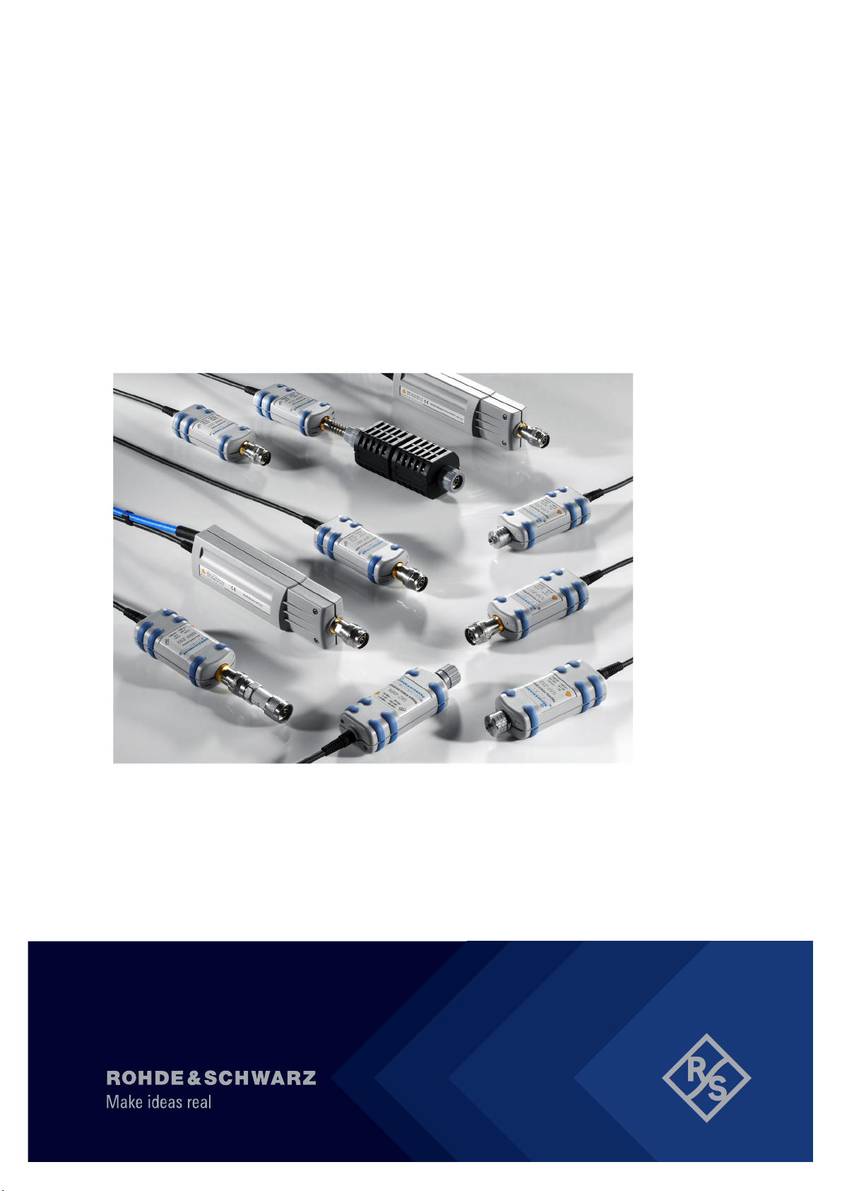
Overview of the R&S NRP‑Z power sensor types
The R&S NRP‑Z power sensors are highly accurate standalone measuring instruments that offer all the functionality of conventional power meters, and more,
within the small housing of a power sensor. With a high dynamic range, the different types of R&S NRP‑Z power sensors are suitable for nearly every measurement task:
Key Features
●
Three-path power sensors
With patented three-path technology. Suitable for many applications, thanks to
their wide dynamic and frequency range. The sensors feature high measurement accuracy independent of the modulation type and speed and offer a
wide range of functions.
●
Two-path power sensors
With slightly modified dynamic range and performance. A cost-effective solution ideal for production applications.
●
Wideband power sensors
With high video bandwidth that permits accurate time-domain analysis of the
envelope power. Analysis is fast and easy thanks to also integrated measurement functions such as automatic pulse analysis.
●
Thermal power sensors
With outstanding measurement accuracy. They are the first choice for power
measurements in the frequency range from DC to 110 GHz as performed in
calibration labs, where measurement accuracy is the key requirement.
●
Average power sensors
Specially developed for EMC applications and cover the required frequency
range from 9 kHz to 6 GHz.
●
Level control sensors
9Getting Started 1176.8822.02 ─ 04
Page 10

R&S®NRP-Zxx
With an integrated splitter that can split the signal into two parts of equal
power. This feature allows you to feed power to a device under test (DUT) and
monitor the power at the same time.
●
Power sensor modules
Developed for level calibration using the R&S FSMR measuring receiver.
You can find an overview of the available sensors and filter according to your
requirements at:
www.rohde-schwarz.com/product/nrpz
Key Features
10Getting Started 1176.8822.02 ─ 04
Page 11
R&S®NRP-Zxx
Preparing for Use
4 Preparing for Use
This section describes the basic steps to be taken when setting up the R&S
NRP‑Z power sensors for the first time.
Risk of injury due to disregarding safety information
Observe the information on appropriate operating conditions provided in the
data sheet to prevent personal injury or damage to the power sensor. Read
and observe the basic safety instructions provided with the power sensor, in
addition to the safety instructions in the following sections. In particular, do
not open the casing of the power sensor.
Risk of electrostatic discharge
Protect the work area against electrostatic discharge to avoid damage to
electronic components in the modules. For details, refer to the general
safety instructions.
Risk of instrument damage due to inappropriate operating conditions
An unsuitable operating site or test setup can damage the power sensor
and to connected devices. Before switching on the power sensor, observe
the information on appropriate operating conditions provided in the data
sheet. In particular, ensure the following:
●
The power sensor is dry and shows no sign of condensation.
●
The power sensor is connected as described in the following sections.
●
The ambient temperature does not exceed the range specified in the
data sheet.
●
Signal levels at the input connectors are all within the specified ranges.
●
Signal outputs are correctly connected and are not overloaded.
11Getting Started 1176.8822.02 ─ 04
Page 12

R&S®NRP-Zxx
Connectors of the R&S NRP‑Z Power Sensors
Preparing for Use
4.1 EMI Suppression
Electromagnetic interference (EMI) can affect the measurement results.
To suppress generated electromagnetic interference:
●
Use suitable shielded cables of high quality. For example, use double-shielded
RF cables.
●
Always terminate open cable ends.
●
Note the EMC classification in the data sheet.
4.2 Unpacking and Checking the Power Sensor
Check the equipment for completeness using the delivery note and the accessory
lists for the various items. Check the power sensor for any damage. If there is
damage, immediately contact the carrier who delivered the instrument. Make sure
not to discard the box and packing material.
Packing material and transportation
Always make sure that sufficient mechanical and electrostatic protection is
provided when transporting the power sensors.
4.3 Connectors of the R&S NRP‑Z Power Sensors
An R&S NRP‑Z power sensor has two connectors, as shown in Figure 4-1.
12Getting Started 1176.8822.02 ─ 04
Page 13

R&S®NRP-Zxx
Preparing for Use
Connectors of the R&S NRP‑Z Power Sensors
Figure 4-1: Connectors of an R&S NRP‑Z power sensor
1 = Host connector
2 = RF connector
Host connector
See (1) in Figure 4-1.
Lemo type host connector. You can plug it:
●
Directly to a compatible Rohde & Schwarz instrument
●
To a R&S NRP2 power meter base unit
●
Using an R&S NRP‑Z3 or R&S NRP‑Z4 USB adapter to a controlling device
(PC or other)
●
Using an R&S NRP‑Z5 USB hub to a controlling device (PC or other)
RF connector
See (2) in Figure 4-1.
13Getting Started 1176.8822.02 ─ 04
Page 14

R&S®NRP-Zxx
Connecting the R&S NRP‑Z Power Sensors
Used to connect the power sensor to a device under test (DUT) or a signal generator.
Caused by their different frequency ranges, the R&S NRP‑Z power sensors have
different RF connectors. Also, for maximal measurement accuracy, the RF connector must be tightened using a torque wrench with a specific nominal torque.
Refer to the operating manual of your R&S NRP‑Z power sensor for information
on your connector and the allowed nominal torque.
Preparing for Use
4.4 Connecting the R&S NRP‑Z Power Sensors
When connecting the R&S NRP-Z27/-Z28/-Z37/-Z98 sensors, there are
additional requirements to fulfill. Refer to the operating manual of the corresponding sensor for a description on how to connect it.
4.4.1 Connecting the RF Connector of the R&S NRP‑Z Power
Sensors
Risk of damage to the center pin of the RF connector
When connecting the power sensor, always rotate only the union nut of the
RF connector. Do not rotate the sensor itself to avoid damage the center pin
of the connector.
1. Refer to the operating manual of your R&S NRP‑Z power sensor to find out
what kind of RF connector your sensor has and the recommended nominal
torque.
2. Insert the RF connector of the attenuator straight into the RF output of your
DUT. Do not tilt it.
14Getting Started 1176.8822.02 ─ 04
Page 15

R&S®NRP-Zxx
Preparing for Use
Connecting the R&S NRP‑Z Power Sensors
3. To ensure a maximal measurement accuracy, tighten the RF connector using
a torque wrench with the recommended nominal torque (see the operating
manual of your power sensor).
4.4.2 Connecting the Host Connector of the R&S NRP‑Z Power
Sensors
To connect to an adapter
You can use an R&S NRP‑Z3 or R&S NRP‑Z4 adapter.
1. Rotate both cables, so that the red markings on the sleeves of both of them
are at the same position.
2. Insert the host connector of your sensor into the connector of your USB
adapter.
Figure 4-2: Connecting the host connector
1 = R&S NRP‑Z4 in this example
2 = Red marking
3 = Host connector
4 = R&S NRP‑Z power sensor
To connect to an R&S NRP‑Z5 sensor hub
► Insert the host connector, red marking upwards, into the SENSOR connector
of your sensor hub.
15Getting Started 1176.8822.02 ─ 04
Page 16

R&S®NRP-Zxx
Disconnecting the R&S NRP‑Z Power Sensors
To connect to an Rohde & Schwarz instrument
► Insert the host connector, red marking upwards, into the SENSOR connector
of your instrument.
Preparing for Use
4.5 Disconnecting the R&S NRP‑Z Power Sensors
Additional requirements must be fulfilled when disconnecting the R&S NRPZ27/-Z28/-Z37/-Z98 sensors. Refer to the operating manual of the corresponding sensor for a description on how to disconnect it.
4.5.1 Disconnecting the RF Connector of the R&S NRP‑Z Power
Sensors
Risk of damage to the center pin of the RF connector
When disconnecting the power sensor, always rotate only the union nut of
the RF connector. Do not rotate the sensor itself to avoid damage the center pin of the connector.
► Carefully loosen the screw at the front of the sensor's RF connector and
remove the sensor.
4.5.2 Disconnecting the Host Connector of the R&S NRP‑Z
Power Sensors
To disconnect from an R&S NRP‑Z3 or R&S NRP‑Z4 adapter
► Pull at the host connector (Figure 4-2 (3) ) until it disconnects from the con-
nector of the USB adapter.
16Getting Started 1176.8822.02 ─ 04
Page 17

R&S®NRP-Zxx
Preparing for Use
Powering the R&S NRP‑Z Power Sensors
To disconnect from an Rohde & Schwarz instrument or an R&S NRP‑Z5 sensor hub
► At the same time, press down the ring of the built-in plug (1) and pull off the
cable sleeve (2).
Figure 4-3: Disconnecting from a SENSOR connector
1 = Ring of the built-in plug
2 = Cable sleeve
4.6 Powering the R&S NRP‑Z Power Sensors
The R&S NRP‑Z power sensors can be powered in two ways:
●
Self-powered from a separate power supply using the R&S NRP‑Z3 active
USB adapter or the R&S NRP‑Z5 sensor hub.
●
Bus-powered from the PC or a USB hub with its own power supply (self-powered hub) using the R&S NRP‑Z3 active USB adapter or the R&S NRP‑Z4
passive USB adapter.
Requirements for the usage in the bus-powered mode:
●
Laptop/PC with a self-powered USB hub
●
Total available current per USB port of 500 mA
17Getting Started 1176.8822.02 ─ 04
Page 18

R&S®NRP-Zxx
Using a Passive USB Adapter
Connecting to a PC
5 Connecting to a PC
There are different possibilities for connecting a power sensor to a PC, which can
differ depending on the type of power sensor and available accessories.
The following chapter gives an overview of the possible setups and what equipment is needed for each of them.
For details on powering the R&S NRP‑Z power sensor, see Chapter 4.6, "Power-
ing the R&S NRP‑Z Power Sensors", on page 17.
5.1 Using a Passive USB Adapter
The R&S NRP‑Z power sensors can be used with the R&S NRP‑Z4 for power
measurements where no external triggering is required.
Required equipment
●
R&S NRP‑Z power sensor
●
R&S NRP‑Z4 passive USB adapter
●
PC with installed R&S NRP Toolkit, see Chapter 6.1, "R&S NRP Toolkit",
on page 24
Setup
Figure 5-1: Setup with a passive USB adapter
1 = Signal source
2 = R&S NRP‑Z power sensor
3 = R&S NRP‑Z4
4 = USB connector
5 = PC with a USB interface
18Getting Started 1176.8822.02 ─ 04
Page 19

R&S®NRP-Zxx
Using an Active USB Adapter
Incorrectly connecting/disconnecting the R&S NRP‑Z power sensors may
damage the power sensors or lead to erroneous results.
Ensure that you connect/disconnect your power sensors as described in
Chapter 4.4, "Connecting the R&S NRP‑Z Power Sensors", on page 14 and
Chapter 4.5, "Disconnecting the R&S NRP‑Z Power Sensors", on page 16.
1. Connect the cables as shown in Figure 5-1:
a) Connect the R&S NRP‑Z4 passive USB adapter to the power sensor.
b) Connect the power sensor passive USB adapter to the computer.
c) Connect the power sensor to the signal source.
2. On the PC, start a software application to view the measurement results. See
Chapter 6, "Operating Concepts", on page 24.
Connecting to a PC
5.2 Using an Active USB Adapter
The R&S NRP‑Z power sensors can be used with the R&S NRP‑Z3 for power
measurements where an external power supply and/or external triggering is
required.
Required equipment
●
R&S NRP‑Z power sensor
●
R&S NRP‑Z3
●
PC with installed R&S NRP Toolkit, see Chapter 6.1, "R&S NRP Toolkit",
on page 24
19Getting Started 1176.8822.02 ─ 04
Page 20

R&S®NRP-Zxx
Setup
Connecting to a PC
Using an Active USB Adapter
Figure 5-2: Setup with an active USB adapter
1 = Signal source
2 = R&S NRP‑Z power sensor
3 = R&S NRP‑Z3
4 = USB connector
5 = PC with a USB interface
6 = Trigger source (optional)
7 = BNC cable (optional, not supplied)
8 = Plug-in power supply (optional, supplied)
9 = AC supply connector (optional)
Incorrectly connecting/disconnecting the R&S NRP‑Z power sensors may
damage the power sensors or lead to erroneous results.
Ensure that you connect/disconnect your power sensors as described in
Chapter 4.4, "Connecting the R&S NRP‑Z Power Sensors", on page 14 and
Chapter 4.5, "Disconnecting the R&S NRP‑Z Power Sensors", on page 16.
1. Connect the cables as shown in Figure 5-2:
a) Connect the R&S NRP‑Z3 active USB adapter to the power sensor.
b) Connect the power sensor passive USB adapter to the computer.
c) Connect the power sensor to the signal source.
d) Connect the R&S NRP‑Z3 with a BNC cable to the trigger source
(optional).
20Getting Started 1176.8822.02 ─ 04
Page 21

R&S®NRP-Zxx
Using an R&S NRP‑Z5 Sensor Hub
e) Connect the delivered plug-in power supply to the R&S NRP‑Z3 and to an
AC supply connector (optional).
2. On the PC, start a software application to view the measurement results. See
Chapter 6, "Operating Concepts", on page 24.
Connecting to a PC
5.3 Using an R&S NRP‑Z5 Sensor Hub
The R&S NRP‑Z5 sensor hub (high-speed USB 2.0) can host up to four R&S
NRP‑Z power sensors and provides simultaneous internal and external triggering
of all connected sensors.
Required equipment
●
R&S NRP‑Z power sensor
●
R&S NRP‑Z5 sensor hub that provides:
– Power supply
– Through-wired trigger bus
– Trigger input and trigger output via BNC sockets
●
PC with installed R&S NRP Toolkit, see Chapter 6.1, "R&S NRP Toolkit",
on page 24
21Getting Started 1176.8822.02 ─ 04
Page 22

R&S®NRP-Zxx
Setup
Connecting to a PC
Using an R&S NRP‑Z5 Sensor Hub
Figure 5-3: Setup with an R&S NRP‑Z5 sensor hub
1 = R&S NRP‑Z5 sensor hub
2 = External power supply unit (supplied)
3 = Power cable (supplied)
4 = AC power supply
5 = USB cable (supplied)
6 = PC with USB host interface
7, 8 = BNC cable (optional, not supplied)
9 = Trigger source (optional)
22Getting Started 1176.8822.02 ─ 04
Page 23

R&S®NRP-Zxx
Connecting to a PC
Using an R&S NRP‑Z5 Sensor Hub
10 = Triggered device (optional)
11-14 = R&S NRP‑Z power sensor
15 = Signal source
Incorrectly connecting/disconnecting the R&S NRP‑Z power sensors may
damage the power sensors or lead to erroneous results.
Ensure that you connect/disconnect your power sensors as described in
Chapter 4.4, "Connecting the R&S NRP‑Z Power Sensors", on page 14 and
Chapter 4.5, "Disconnecting the R&S NRP‑Z Power Sensors", on page 16.
1. Connect the cables as shown in Figure 5-3:
a) Connect the power sensors to the R&S NRP‑Z5 sensor hub. You can con-
nect up to four sensors.
b) Connect the R&S NRP‑Z5 to the computer.
c) Connect the power sensors to the signal source.
d) Connect the delivered external power supply unit to the R&S NRP‑Z5 and
to an AC supply connector.
e) Connect the R&S NRP‑Z5 with a BNC cable to the trigger source
(optional).
f) Connect the R&S NRP‑Z5 with a BNC cable to the trigger device
(optional).
2. On the PC, start a software application to view the measurement results. See
Chapter 6, "Operating Concepts", on page 24.
23Getting Started 1176.8822.02 ─ 04
Page 24

R&S®NRP-Zxx
Operating Concepts
R&S NRP Toolkit
6 Operating Concepts
For operating the power sensor, you can choose from various possibilities.
Alternative to the methods of access described in this chapter, you can use
remote control. For details, see:
●
Chapter 7, "Remote Control", on page 37
●
Operating manual of the R&S NRP‑Z power sensor
● R&S NRP Toolkit.............................................................................................24
● R&S NRPV......................................................................................................29
● R&S Power Viewer..........................................................................................31
● R&S Power Viewer Mobile.............................................................................. 32
● R&S NRP2...................................................................................................... 32
● Compatible Instrument.................................................................................... 34
6.1 R&S NRP Toolkit
Before you start using the power sensors with a software solution, you have
to install the R&S NRP Toolkit.
The R&S NRP Toolkit is the basic software package that supplies low-level drivers and tools for all power sensors. It is provided on your documentation CDROM and on the Rohde & Schwarz website. The content of the toolkit depends
on your operating system.
To ensure that your power sensor is recognized properly by your system,
first install the R&S NRP Toolkit on your laptop/PC and then connect your
power sensor for the first time.
6.1.1 System Requirements
Hardware requirements:
●
Desktop PC or laptop, or an Intel-based Apple Mac
●
USB interface
24Getting Started 1176.8822.02 ─ 04
Page 25

R&S®NRP-Zxx
●
R&S NRP‑Z3 or R&S NRP‑Z4 USB adapter or R&S NRP‑Z5 sensor hub
Supported operating systems:
●
Microsoft Windows Vista 32/64-bit
●
Microsoft Windows 7 32/64-bit
●
Microsoft Windows 8 32/64-bit
●
Microsoft Windows 10 32/64-bit
●
Microsoft Windows XP 32-bit is available on request only.
R&S NRP Toolkit versions for Linux distributions and MacOSX are also available
on request. To obtain an R&S NRP Toolkit for an operating system other than
Microsoft Windows, contact the Rohde & Schwarz customer support:
customersupport@rohde-schwarz.com
Operating Concepts
R&S NRP Toolkit
6.1.2 Windows Operating System
The R&S NRP Toolkit installer version for Windows-based systems contains the
following components. Obligatory components are indicated.
●
USB driver (obligatory)
●
High level dynamic link library (NrpControl2) (obligatory)
●
R&S NRP Toolkit SDK
●
S-Parameter tool
Program modules for loading an S-parameter table into the power sensor
●
R&S NRP‑Z uncertainty calculator and its PDF manual
●
VxI plug&play with programming examples
For installation, enable "NRP-Toolkit-SDK" during the installation of the
R&S NRP Toolkit.
●
Terminal (NrpTerm): low-level communication program for sending commands
to the power sensor
●
Firmware update (PureFW)
●
Nrp Version Collector
Tool for displaying version information of all installed, power measurement-relevant software packages.
To install the R&S NRP Toolkit
1. Start the R&S NRP Toolkit installer.
25Getting Started 1176.8822.02 ─ 04
Page 26

R&S®NRP-Zxx
2. In the "Choose Components" dialog, select the components you want to install
and accept the license terms to continue with the installation
Operating Concepts
R&S NRP Toolkit
3. Click "Next" and complete the installation process.
6.1.3 Linux-Based Systems
The R&S NRP Toolkit for a certain Linux distribution comes as a series of Debian
(*.deb) or RPM (*.rpm) files. These files become installed through the standard
installation process of the individual Linux distribution. See the ReadMe file that
accompanies the R&S NRP Toolkit for further instructions.
6.1.4 Mac OS X
The R&S NRP Toolkit installer version for Mac OS X contains the following components:
●
Low-level driver: RsNrpLib.framework
●
VXI PnP driver: RsNrpz.framework
●
HTML help files for the VXI PnP driver
●
Power Viewer Plus and its PDF manual
●
Example programs for use with VXI PnP driver
26Getting Started 1176.8822.02 ─ 04
Page 27

R&S®NRP-Zxx
To install the R&S NRP Toolkit
1. In the Mac OS X Finder, double-click the provided .dmg disk image to mount
it.
2. Double-click the NrpToolkit.mpkg installer to start the installation.
The R&S NRP Toolkit installer opens. The welcome message gives an overview of the packages that are part of the installer and indicates their default
installation location.
Operating Concepts
R&S NRP Toolkit
3. Accept the license terms to continue with the installation.
4. Select the components you want to install and click "Continue" to complete
the installation process.
27Getting Started 1176.8822.02 ─ 04
Page 28

R&S®NRP-Zxx
Operating Concepts
R&S NRP Toolkit
a) R&S NRP-Z Driver Framework (obligatory).
b) Enable the "Power Viewer Plus application" (optional).
c) Enable "Application Development" (optional). You can use these examples
as starting points for your own implementations.
5. Click "Continue" and complete the installation process.
After a successful installation, you can start the applications provided with the
R&S NRP Toolkit from the Rohde-Schwarz folder that was created in the
Mac OS X application directory.
28Getting Started 1176.8822.02 ─ 04
Page 29

R&S®NRP-Zxx
Operating Concepts
R&S NRPV
6.1.5 Performing a Firmware Update
Use the firmware update program (PureFW) to load new firmware for the power
sensors. It is part of the R&S NRP Toolkit that is supplied on a CD-ROM together
with the power sensors. For further details, refer to the operating manual.
6.2 R&S NRPV
The R&S NRPV enables you to measure power in all available measurement
modes. Also, you can use up to four power sensors simultaneously.
The R&S NRPV software can be installed on any Windows PC. It is provided on
your documentation CD-ROM and on the Rohde & Schwarz website as a separate standalone installation package. To make full use of its functionalities, you
must activate your R&S NRP‑Z power sensor with a license key.
Required equipment
●
R&S NRP‑Z power sensor
●
R&S NRP‑Z3, R&S NRP‑Z4 or R&S NRP‑Z5
●
Windows PC with installed:
– R&S NRP Toolkit
– R&S NRPV (refer to the operating manual of the R&S NRPV for a descrip-
tion of the installation process)
●
License key (R&S NRPZ-K1 option) for activating the power measurements
for your R&S NRP‑Z power sensor
Setup
Figure 6-1: Setup with an R&S NRP‑Z4 and an R&S NRPV
29Getting Started 1176.8822.02 ─ 04
Page 30

R&S®NRP-Zxx
1 = Signal source
2 = R&S NRP‑Z power sensor
3 = R&S NRP‑Z4
4 = USB connector
5 = PC with installed R&S NRPV
Operating Concepts
Incorrectly connecting/disconnecting the R&S NRP‑Z power sensors may
damage the power sensors or lead to erroneous results.
Ensure that you connect/disconnect your power sensors as described in
Chapter 4.4, "Connecting the R&S NRP‑Z Power Sensors", on page 14 and
Chapter 4.5, "Disconnecting the R&S NRP‑Z Power Sensors", on page 16.
Starting a measurement
1. Connect the power sensor to the PC as shown in Figure 6-1.
R&S NRPV
2. On the PC, start the R&S NRPV software.
3. Connect the power sensor to the PC. For a detailed description, see Chap-
ter 5, "Connecting to a PC", on page 18.
4. If you use the power sensor for the first time with the R&S NRPV software,
activate the sensor using a license key:
a) In the "File" menu, select "File" > "Licensing".
The "Licensing NRP-Z Power Sensors for NRPV" dialog opens.
b) Select your power sensor.
c) Select "Enter License".
The "License Activation" dialog opens.
d) Enter the license key either manually or with the key code file.
30Getting Started 1176.8822.02 ─ 04
Page 31

R&S®NRP-Zxx
e) Confirm with "OK" to return to the "Licensing NRP-Z Power Sensors for
NRPV" dialog. The dialog indicates all currently connected sensors.
Note: If you want to evaluate the R&S NRPV before buying a license for your
power sensor, you can activate a sensor for temporary use. To do so, select
"Evaluate Without License" in the "Licensing NRP-Z Power Sensors for
NRPV" dialog. For a detailed description, refer to the operating manual of the
R&S NRPV.
5. Switch on the test signal of the signal source.
6. To start a continuous measurement, select "Measure" > "Continuous".
The "Continuous" measurement window appears. It shows the measurement
results numerically, and the control panel for accessing further dialogs with
parameters for measurement, evaluation and display.
Operating Concepts
R&S Power Viewer
For a detailed description of how to measure in this setup, refer to the operating
manual of the R&S NRPV.
6.3 R&S Power Viewer
The R&S Power Viewer is software that simplifies many measurement tasks. It is
provided on your documentation CD-ROM and on the Rohde & Schwarz website
as a separate standalone installation package.
31Getting Started 1176.8822.02 ─ 04
Page 32

R&S®NRP-Zxx
For details on installing and operating the R&S Power Viewer, refer to its operating manual. The manual is provided on the documentation CD-ROM and is installed automatically during the installation of the R&S Power Viewer.
If you want to use an android device like a tablet or a smartphone, use the
R&S Power Viewer Mobile. For details, see Chapter 6.4, "R&S Power
Viewer Mobile", on page 32.
Operating Concepts
R&S NRP2
6.4 R&S Power Viewer Mobile
The R&S Power Viewer Mobile extends the functionality of the R&S Power
Viewer to Android-based devices, such as a smartphone and tablets.
You can download the R&S Power Viewer Mobile free of charge from the Google
Play Store.
The 1MA215 "Using R&S®NRP Series Power Sensors with AndroidTM Handheld
Devices" application note gives a detailed description on installation and features
of the R&S Power Viewer Mobile. The application note is provided on the documentation CD-ROM.
6.5 R&S NRP2
With the R&S NRP‑Z power sensors and an R&S NRP2, you can measure power
with up to four power sensors simultaneously, depending on the base unit configuration. All sensor-dependent measurement functions can be used and the
results can be displayed in parallel.
Required equipment
●
R&S NRP‑Z power sensor
●
R&S NRP2 base unit
32Getting Started 1176.8822.02 ─ 04
Page 33

R&S®NRP-Zxx
Setup
Figure 6-2: Setup with an R&S NRP2 base unit
1 = Signal source
2 = R&S NRP‑Z power sensor
3 = SENSOR connector of the R&S NRP2
4 = R&S NRP2 base unit
Operating Concepts
R&S NRP2
Incorrectly connecting/disconnecting the R&S NRP‑Z power sensors may
damage the power sensors or lead to erroneous results.
Ensure that you connect/disconnect your power sensors as described in
Chapter 4.4, "Connecting the R&S NRP‑Z Power Sensors", on page 14 and
Chapter 4.5, "Disconnecting the R&S NRP‑Z Power Sensors", on page 16.
Starting a measurement
1. Connect the power sensor to the [SENSOR] connector of the R&S NRP2 as
shown in Figure 6-2.
2. Preset the R&S NRP2.
3. Execute zeroing.
Note: Turn off all test signals before zeroing. An active test signal during zeroing causes an error.
4. Connect the power sensor to the signal source.
The result window indicates the result (in dBm) obtained with sensor A.
33Getting Started 1176.8822.02 ─ 04
Page 34

R&S®NRP-Zxx
5. If necessary, perform further settings.
For a detailed description of how to measure in this setup, refer to the operating
manual of your R&S NRP2.
Operating Concepts
Compatible Instrument
6.6 Compatible Instrument
Many Rohde & Schwarz instruments allow power measurements using the R&S
NRP‑Z power sensors. For example, the power sensors can be used with a signal
generator to achieve stable and accurate RF power, which can be further supplied to your DUT.
You can connect the power sensors to the following instrument connectors:
●
Directly to the SENSOR connector
●
To the USB port of the instrument, using an R&S NRP‑Z3 or R&S NRP‑Z4
USB adapter
●
To the USB port of the instrument, using an R&S NRP‑Z5 USB hub
Refer to the operating manual of your Rohde & Schwarz instrument to find out if it
supports power measurements with the R&S NRP‑Z power sensors.
Required equipment
●
R&S NRP‑Z power sensor
●
Compatible Rohde & Schwarz instrument
●
R&S NRP‑Z3 or R&S NRP‑Z4 USB adapter or an R&S NRP‑Z5 sensor hub
(optional)
34Getting Started 1176.8822.02 ─ 04
Page 35

R&S®NRP-Zxx
Setup
Figure 6-3: Setup with an R&S SMF
1 = R&S SMF
2 = Device under test (DUT)
3 = R&S NRP‑Z icon
4 = [SENSOR] connector
5 = R&S NRP‑Z Power Sensors
6 = RF output of the DUT
7 = [RF OUT] connector of the R&S SMF
8 = RF input of the DUT
Operating Concepts
Compatible Instrument
Incorrectly connecting/disconnecting the R&S NRP‑Z power sensors may
damage the power sensors or lead to erroneous results.
Ensure that you connect/disconnect your power sensors as described in
Chapter 4.4, "Connecting the R&S NRP‑Z Power Sensors", on page 14 and
Chapter 4.5, "Disconnecting the R&S NRP‑Z Power Sensors", on page 16.
Starting a measurement
1. Connect the cables as shown in Figure 6-3:
a) Connect the DUT to the [RF OUT] connector of the R&S SMF.
b) Connect the DUT to the [RF] connector of the power sensor.
c) Connect the power sensor to the [SENSOR] connector of the R&S SMF.
2. On the R&S SMF, open the "NRP-Z Power Viewer" dialog.
35Getting Started 1176.8822.02 ─ 04
Page 36

R&S®NRP-Zxx
The dialog shows the result (in dBm) and some additional parameters.
3. If necessary, perform further settings.
Operating Concepts
Compatible Instrument
For a detailed description of how to measure in this setup, refer to the operating
manual your compatible Rohde & Schwarz instrument.
36Getting Started 1176.8822.02 ─ 04
Page 37

R&S®NRP-Zxx
Remote Control
7 Remote Control
Use remote control to integrate the R&S NRP‑Z power sensors into custom automatic test equipment (ATE) systems. The latest version of the available instrument drivers is part of the R&S NRP Toolkit SDK under Windows.
For a detailed description on how to perform different remote measurements,
refer to various sample programs installed with the R&S NRP Toolkit SDK, or the
application note "1GP69: R&S®NRP-Z Power Sensor Programming Guide".
37Getting Started 1176.8822.02 ─ 04
Page 38

R&S®NRP-Zxx
Contacting Customer Support
8 Contacting Customer Support
Technical support – where and when you need it
For quick, expert help with any Rohde & Schwarz product, contact our customer
support center. A team of highly qualified engineers provides support and works
with you to find a solution to your query on any aspect of the operation, programming or applications of Rohde & Schwarz products.
Contact information
Contact our customer support center at www.rohde-schwarz.com/support, or fol-
low this QR code:
Figure 8-1: QR code to the Rohde & Schwarz support page
38Getting Started 1176.8822.02 ─ 04
Page 39

R&S®NRP-Zxx
Index
Index
A
Android device
R&S Power Viewer Mobile ..................32
Application cards ....................................... 7
Application notes ....................................... 7
B
Brochures .................................................. 7
C
Checking the delivery .............................. 12
Connecting
Host connector ....................................15
RF ....................................................... 14
To a PC ...............................................18
Connector
Host .................................................... 13
Overview .............................................12
RF ....................................................... 13
Customer support ....................................38
D
Data sheets ............................................... 7
Disconnecting
Host connector ....................................16
RF ....................................................... 16
Documentation overview ........................... 6
E
EMI suppression ......................................12
F
Firmware update ..................................... 29
G
Getting started ...........................................6
H
Host connector ........................................ 13
I
Instrument
Supporting power measurement .........34
Instrument security procedures ................. 6
Intended use ..............................................5
Interface
Overview .............................................12
Introduction ................................................8
M
Mobile measurements ............................. 32
O
Open source acknowledgment (OSA) .......7
Operating concepts ................................. 24
App for Android devices ......................32
Compatible instrument ........................34
R&S NRP Toolkit .................................24
R&S NRP2 ..........................................32
R&S NRPV ......................................... 29
R&S Power Viewer ............................. 31
P
PC
Active USB adapter ............................ 19
Connection types ................................ 18
Passive USB adapter ..........................18
USB sensor hub ..................................21
Powering the R&S NRP‑Z power sensor 17
Preparing for use ..................................... 11
R
R&S NRP Toolkit ..................................... 24
Components for Windows-based sys-
tems .................................................... 25
Installation under Linux .......................26
Installation under Mac OS X ............... 26
Installation under Windows .................25
System requirements ..........................24
R&S NRP‑Z5 ........................................... 21
R&S NRP2 .............................................. 32
R&S NRPV .............................................. 29
R&S Power Viewer ..................................31
R&S Power Viewer Mobile ...................... 32
Release notes ........................................... 7
Remote control ........................................ 37
RF connector ...........................................13
S
Safety information ..................................... 5
Safety instructions ..................................... 7
39Getting Started 1176.8822.02 ─ 04
Page 40

R&S®NRP-Zxx
Security procedures .................................. 6
T
Tutorials .....................................................6
U
Unpacking the delivery ............................ 12
USB connection .................................18, 19
USB sensor hub ...................................... 21
User manual .............................................. 6
W
White papers ............................................. 7
Index
40Getting Started 1176.8822.02 ─ 04
 Loading...