

Page 1
R&S®NRPxxTWG
Thermal Waveguide Power Sensors
User Manual
(;ÜáÕ2)
1178837102
User Manual
Version 04
Page 2

This manual describes the following thermal waveguide power sensors with firmware version FW 02.00
and later:
●
R&S®NRP75TWG (1700.2529.02)
●
R&S®NRP90TWG (1700.2312.02)
●
R&S®NRP110TWG (1173.8709.02)
© 2019 Rohde & Schwarz GmbH & Co. KG
Mühldorfstr. 15, 81671 München, Germany
Phone: +49 89 41 29 - 0
Fax: +49 89 41 29 12 164
Email: [email protected]
Internet: www.rohde-schwarz.com
Subject to change – Data without tolerance limits is not binding.
R&S® is a registered trademark of Rohde & Schwarz GmbH & Co. KG.
Trade names are trademarks of the owners.
1178.8371.02 | Version 04 | R&S®NRPxxTWG
Throughout this manual, products from Rohde & Schwarz are indicated without the ® symbol, for example R&S®NRP75TWG is
abbreviated as R&S NRP75TWG.
Page 3

R&S®NRPxxTWG
1 Preface.................................................................................................... 7
1.1 For Your Safety..............................................................................................................7
1.2 Documentation Overview............................................................................................. 7
1.2.1 Getting Started Manual................................................................................................... 7
1.2.2 User Manuals.................................................................................................................. 7
1.2.3 Tutorials...........................................................................................................................8
1.2.4 Instrument Security Procedures......................................................................................8
1.2.5 Basic Safety Instructions.................................................................................................8
1.2.6 Data Sheets and Brochures............................................................................................ 8
1.2.7 Release Notes and Open Source Acknowledgment (OSA)............................................ 8
1.2.8 Application Notes, Application Cards, White Papers, etc................................................8
Contents
Contents
1.3 Typographical Conventions......................................................................................... 9
2 Key Features.........................................................................................10
3 Preparing for Use................................................................................. 11
3.1 Unpacking and Checking the Power Sensor............................................................ 11
3.2 Operating Conditions..................................................................................................11
3.3 Important Aspects for Test Setup.............................................................................. 11
3.4 Connecting to a DUT...................................................................................................12
3.5 Connecting to a Computer......................................................................................... 13
3.5.1 Setting Up a USB Connection.......................................................................................13
3.5.1.1 Simple USB Connection................................................................................................13
3.5.1.2 R&S NRP‑Z5 Sensor Hub Setup.................................................................................. 14
3.6 Connecting to a USB Host......................................................................................... 16
4 Power Sensor Tour.............................................................................. 17
4.1 RF Connector.............................................................................................................. 17
4.2 Trigger I/O Connector................................................................................................. 17
4.3 Host Interface.............................................................................................................. 18
4.4 Status LED................................................................................................................... 18
5 Operating Concepts.............................................................................19
5.1 R&S NRP Toolkit..........................................................................................................19
3User Manual 1178.8371.02 ─ 04
Page 4

R&S®NRPxxTWG
5.1.1 Versions and Downloads...............................................................................................19
5.1.2 System Requirements...................................................................................................19
5.1.3 R&S NRP Toolkit for Windows...................................................................................... 20
5.1.3.1 Components of the R&S NRP Toolkit............................................................................21
5.2 Remote Control........................................................................................................... 22
5.3 R&S NRPV....................................................................................................................22
5.4 R&S Power Viewer...................................................................................................... 24
5.5 R&S Power Viewer Mobile..........................................................................................26
5.6 R&S NRX...................................................................................................................... 26
5.7 R&S NRP2.................................................................................................................... 28
6 Firmware Update..................................................................................31
6.1 Hardware and Software Requirements..................................................................... 31
Contents
6.2 Updating the Firmware............................................................................................... 31
6.2.1 Using the Firmware Update for NRP Family Program.................................................. 31
6.2.2 Using Remote Control...................................................................................................33
7 Remote Control Commands................................................................35
7.1 Conventions Used in SCPI Command Descriptions................................................35
7.2 Notations......................................................................................................................35
7.3 Common Commands.................................................................................................. 37
7.4 Preparing for the Measurement................................................................................. 41
7.4.1 Selecting the Reference Source................................................................................... 41
7.4.2 Selecting a Measurement Mode................................................................................... 41
7.5 Controlling the Measurement.................................................................................... 42
7.5.1 Starting and Ending a Measurement.............................................................................42
7.5.2 Triggering...................................................................................................................... 43
7.5.2.1 Trigger States................................................................................................................44
7.5.2.2 Waiting for a Trigger Event............................................................................................44
7.5.2.3 Trigger Sources.............................................................................................................44
7.5.2.4 Dropout Time.................................................................................................................45
7.5.2.5 Hold-Off Time................................................................................................................45
7.5.3 Controlling the Measurement Results........................................................................... 46
7.5.4 Interplay of the Controlling Mechanisms....................................................................... 46
7.5.4.1 Continuous Average Mode............................................................................................47
4User Manual 1178.8371.02 ─ 04
Page 5

R&S®NRPxxTWG
7.5.5 Configuring the Trigger..................................................................................................48
7.6 Configuring and Retrieving Results..........................................................................54
7.6.1 Setting the Power Unit.................................................................................................. 54
7.6.2 Setting the Result Format............................................................................................. 55
7.6.3 Retrieving Results......................................................................................................... 56
7.7 Configuring the Measurement Modes.......................................................................56
7.7.1 Continuous Average Measurement...............................................................................57
7.8 Configuring Basic Measurement Parameters.......................................................... 60
7.8.1 Configuring Auto Averaging.......................................................................................... 60
7.8.2 Setting the Frequency................................................................................................... 63
7.8.3 Configuring Corrections................................................................................................ 64
7.8.3.1 Duty Cycle Corrections................................................................................................. 64
7.8.3.2 Offset Corrections......................................................................................................... 64
Contents
7.8.3.3 S-Parameter Correction................................................................................................ 65
7.8.3.4 S-Gamma Corrections.................................................................................................. 67
7.8.3.5 Using the S-Parameters Tool........................................................................................ 69
7.9 Calibrating/Zeroing the Power Sensor .....................................................................78
7.10 Testing the Power Sensor.......................................................................................... 81
7.11 Configuring the System..............................................................................................81
7.12 Using the Status Register.......................................................................................... 93
7.12.1 General Status Register Commands............................................................................ 94
7.12.2 Reading Out the CONDition Part.................................................................................. 94
7.12.3 Reading Out the EVENt Part.........................................................................................95
7.12.4 Controlling the ENABle Part..........................................................................................95
7.12.5 Controlling the Negative Transition Part........................................................................95
7.12.6 Controlling the Positive Transition Part......................................................................... 96
8 Performing Measurement Tasks - Programming Examples............ 97
8.1 Performing the Simplest Measurement.................................................................... 97
8.2 Performing a Buffered Continuous Average Measurement....................................97
9 Remote Control Basics......................................................................100
9.1 Remote Control Interfaces and Protocols.............................................................. 100
9.1.1 USB Interface..............................................................................................................100
9.2 SCPI Command Structure........................................................................................ 101
5User Manual 1178.8371.02 ─ 04
Page 6

R&S®NRPxxTWG
9.2.1 Syntax for Common Commands................................................................................. 101
9.2.2 Syntax for Device-Specific Commands.......................................................................102
9.2.3 SCPI Parameters........................................................................................................ 103
9.2.4 Overview of Syntax Elements..................................................................................... 106
9.2.5 Structure of a Command Line..................................................................................... 106
9.2.6 Responses to Queries.................................................................................................107
9.3 Status Reporting System......................................................................................... 107
9.3.1 Hierarchy of the Status Registers............................................................................... 107
9.3.2 Structure of a SCPI Status Register............................................................................108
9.3.3 Status Byte (STB) and Service Request Enable Register (SRE)................................110
9.3.4 IST Flag and Parallel Poll Enable Register (PPE).......................................................111
9.3.5 Device Status Register................................................................................................112
9.3.6 Questionable Status Register......................................................................................113
Contents
9.3.6.1 Questionable Power Status Register...........................................................................114
9.3.6.2 Questionable Calibration Status Register....................................................................114
9.3.7 Standard Event Status and Enable Register (ESR, ESE)...........................................115
9.3.8 Operation Status Register........................................................................................... 116
9.3.8.1 Operation Calibrating Status Register.........................................................................117
9.3.8.2 Operation Measuring Status Register......................................................................... 118
9.3.8.3 Operation Trigger Status Register...............................................................................118
9.3.8.4 Operation Sense Status Register................................................................................119
9.3.8.5 Operation Lower Limit Fail Status Register.................................................................119
9.3.8.6 Operation Upper Limit Fail Status Register.................................................................120
10 Troubleshooting................................................................................. 121
10.1 Displaying Status Information................................................................................. 121
10.2 Performing a Selftest................................................................................................ 121
10.3 Problems during a Firmware Update...................................................................... 121
List of Commands..............................................................................123
Index....................................................................................................127
6User Manual 1178.8371.02 ─ 04
Page 7

R&S®NRPxxTWG
1 Preface
1.1 For Your Safety
Preface
Documentation Overview
This chapter provides safety related information, an overview of the user documentation and the conventions used in the documentation.
The R&S NRPxxTWG is designated for use in industrial, administrative, and laboratory
environments. Use the R&S NRPxxTWG only for its designated purpose. Observe the
safety and usage instructions documented in the user manual, as well as operating
conditions and performance limits stated in the data sheet.
The product documentation helps you to use the R&S NRPxxTWG safely and efficiently. Keep the product documentation in a safe place and pass it on to the subsequent users.
Safety information is part of the product documentation. It warns you about the potential dangers and gives instructions how to prevent personal injury or damage caused
by dangerous situations. Safety information is provided as follows:
●
In the "Basic Safety Instructions", safety issues are grouped according to subjects.
For example, one subject is electrical safety. The "Basic Safety Instructions" are
delivered with the R&S NRPxxTWG in different languages in print.
●
Throughout the documentation, safety instructions are provided when you need to
take care during setup or operation. Always read the safety instructions carefully.
Make sure to comply fully with them. Do not take risks and do not underestimate
the potential danger of small details such as a damaged power cable.
1.2 Documentation Overview
This section provides an overview of the R&S NRPxxTWG user documentation. Unless
specified otherwise, you find the documents on the R&S NRPxxTWG product page at:
www.rohde-schwarz.com/product/nrp-twg
1.2.1 Getting Started Manual
Introduces the R&S NRPxxTWG and describes how to set up and start working with
the product. Includes basic operations and general information, e.g. safety instructions,
etc. A printed version is delivered with the power sensor.
1.2.2 User Manuals
Contains the description of all instrument modes and functions. It also provides an
introduction to remote control, a complete description of the remote control commands
7User Manual 1178.8371.02 ─ 04
Page 8

R&S®NRPxxTWG
1.2.3 Tutorials
1.2.4 Instrument Security Procedures
1.2.5 Basic Safety Instructions
Preface
Documentation Overview
with programming examples, and information on maintenance and interfaces. Includes
the contents of the getting started manual.
Tutorials offer guided examples and demonstrations on operating the R&S
NRPxxTWG. They are provided on the product page of the internet.
Deals with security issues when working with the R&S NRPxxTWG in secure areas. It
is available for download on the Internet.
Contains safety instructions, operating conditions and further important information.
The printed document is delivered with the instrument.
1.2.6 Data Sheets and Brochures
The data sheet contains the technical specifications of the R&S NRPxxTWG. It also
lists the firmware applications and their order numbers, and optional accessories.
The brochure provides an overview of the instrument and deals with the specific characteristics.
www.rohde-schwarz.com/brochure-datasheet/nrp-twg
1.2.7 Release Notes and Open Source Acknowledgment (OSA)
The release notes list new features, improvements and known issues of the current
firmware version, and describe the firmware installation.
The open source acknowledgment document provides verbatim license texts of the
used open source software.
www.rohde-schwarz.com/firmware/nrp-twg
1.2.8 Application Notes, Application Cards, White Papers, etc.
These documents deal with special applications or background information on particular topics.
8User Manual 1178.8371.02 ─ 04
Page 9
R&S®NRPxxTWG
1.3 Typographical Conventions
Preface
Typographical Conventions
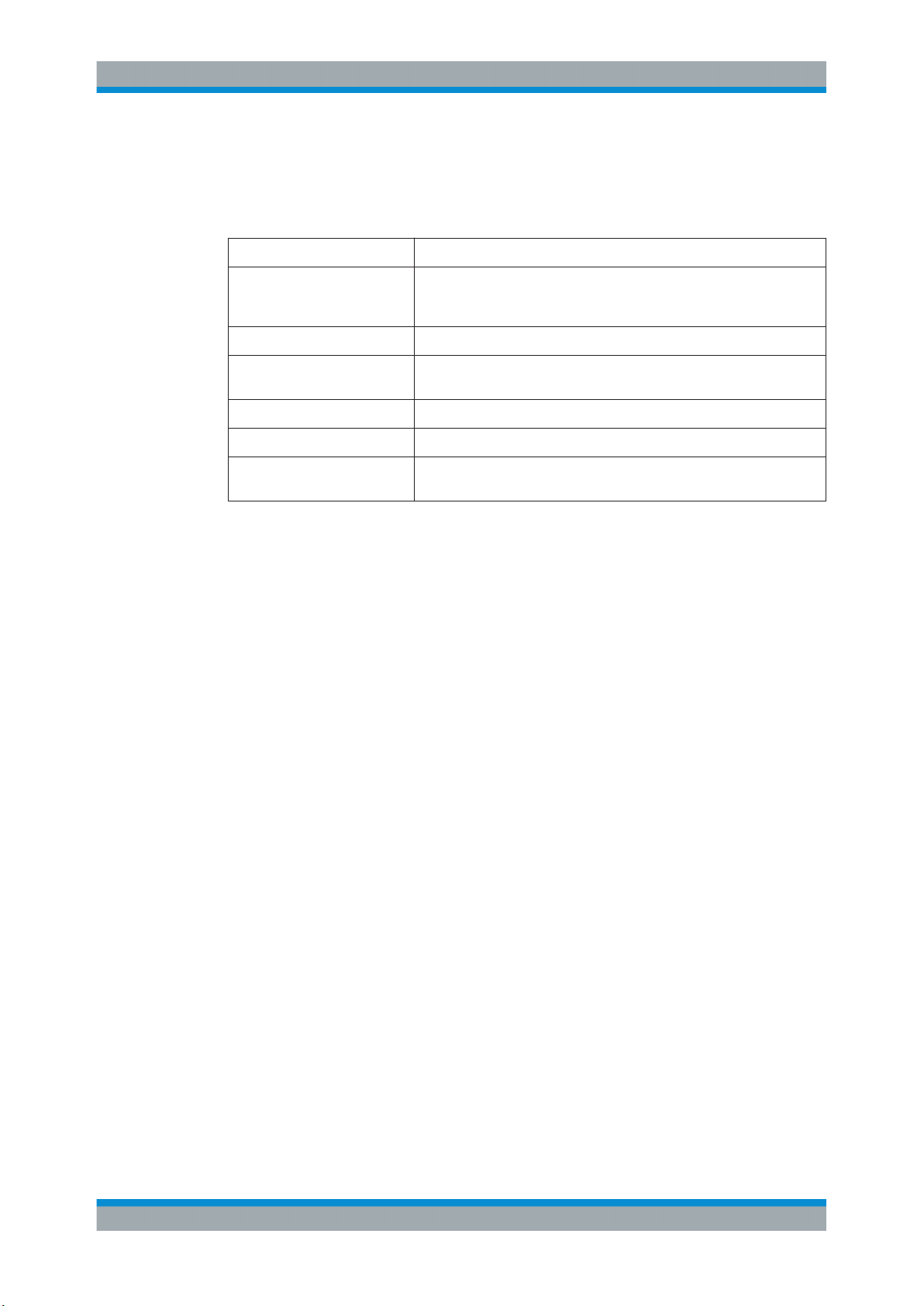
The following text markers are used throughout this documentation:
Convention Description
"Graphical user interface elements"
[Keys] Key and knob names are enclosed by square brackets.
Filenames, commands,
program code
Input Input to be entered by the user is displayed in italics.
Links Links that you can click are displayed in blue font.
"References" References to other parts of the documentation are enclosed by quota-
All names of graphical user interface elements on the screen, such as
dialog boxes, menus, options, buttons, and softkeys are enclosed by
quotation marks.
Filenames, commands, coding samples and screen output are distinguished by their font.
tion marks.
9User Manual 1178.8371.02 ─ 04
Page 10

R&S®NRPxxTWG
2 Key Features
Key Features
The thermal waveguide power sensors are members of the R&S NRP series power
sensors from Rohde & Schwarz.
They provide a high-speed USB interface that constitutes both the communication port
and the power supply connection.
The R&S NRP series power sensors are compatible with the R&S NRP‑Z power sensors in both the interface (USB) and a common command subset. This compatibility
makes the replacement of the old power sensors easy.
For a detailed specification, refer to the data sheet.
10User Manual 1178.8371.02 ─ 04
Page 11
R&S®NRPxxTWG
3 Preparing for Use
3.1 Unpacking and Checking the Power Sensor
Preparing for Use
Important Aspects for Test Setup
For information on safety, see:
●
Chapter 1.1, "For Your Safety", on page 7
●
Chapter 3.2, "Operating Conditions", on page 11
Check the equipment for completeness using the delivery note and the accessory lists
for the various items. Check the power sensor for any damage. If there is damage,
immediately contact the carrier who delivered the power sensor. Make sure not to discard the box and packing material.
Packing material
Retain the original packing material. If the instrument needs to be transported or shipped later, you can use the material to protect the control elements and connectors.
3.2 Operating Conditions
Specific operating conditions are required to ensure accurate measurements and to
avoid damage to the power sensor and connected devices. Before switching on the
power sensor, observe the information on appropriate operating conditions provided in
the basic safety instructions and the data sheet of the power sensor.
In particular, ensure the following:
●
The power sensor is dry and shows no sign of condensation.
●
The ambient temperature does not exceed the range specified in the data sheet.
●
Signal levels at the input connectors are all within the specified ranges.
●
Signal outputs are connected correctly and are not overloaded.
3.3 Important Aspects for Test Setup
Preventing electrostatic discharge (ESD)
ESD is most likely to occur when you connect or disconnect a DUT.
NOTICE! Risk of electrostatic discharge (ESD). Electrostatic discharge (ESD) can
►
damage the electronic components of the power sensor and the device under test
(DUT).
Ground yourself to avoid electrostatic discharge (ESD) damage:
11User Manual 1178.8371.02 ─ 04
Page 12
R&S®NRPxxTWG
3.4 Connecting to a DUT
Preparing for Use
Connecting to a DUT
● Use a wrist strap and cord, and connect yourself to the ground.
● Use a conductive floor mat and heel strap combination.
EMI impact on measurement results
Electromagnetic interference (EMI) may affect the measurement results.
To suppress generated electromagnetic interference (EMI):
●
Use suitable shielded cables of high quality. For example, use double-shielded RF
and LAN cables.
●
Always terminate open cable ends.
●
Note the EMC classification in the data sheet.
For connecting the power sensor to a DUT, use the RF connector of the power sensor.
For details, see Chapter 4.1, "RF Connector", on page 17.
Risk of overloading the sensor
Using a power sensor at a level above its upper measuring limit can damage the sensor head. To avoid this risk, make sure not to exceed the test limit.
The test limits specified on the type label are valid only for the supplied attenuator. For
operation without attenuator, lower test limits apply, as specified in the data sheet.
To connect to the DUT
1. Ensure that the RF connector of your DUT is compatible with the RF connector of
the power sensor.
2. Insert the RF connector straight into the RF output of your DUT. Take care not to tilt
it.
180
NOTICE! Risk of damaging the center pin of the RF connector. Always rotate only
3.
the hex nut of the RF connector. Never rotate the power sensor itself.
Tighten the RF connector manually.
4. To ensure maximum measurement accuracy, tighten the RF connector using a torque wrench with the nominal torque recommended in Chapter 4.1, "RF Connector",
on page 17.
12User Manual 1178.8371.02 ─ 04
Page 13

R&S®NRPxxTWG
3.5 Connecting to a Computer
Preparing for Use
Connecting to a Computer
To disconnect from the DUT
NOTICE! Risk of damaging the center pin of the RF connector. Always rotate only
►
the hex nut of the RF connector. Never rotate the power sensor itself.
Carefully loosen the union nut at the front of the RF connector of the sensor and
remove the sensor.
For operating the power sensor, you can choose from various possibilities. For details,
see Chapter 5, "Operating Concepts", on page 19.
You can establish the connection using one of the following interfaces:
●
Host interface
Contents:
● Setting Up a USB Connection.................................................................................13
3.5.1 Setting Up a USB Connection
You can connect a R&S NRPxxTWG to a computer using the host interface and control
it as described in Chapter 5, "Operating Concepts", on page 19.
Further information:
●
Chapter 9.1, "Remote Control Interfaces and Protocols", on page 100
3.5.1.1 Simple USB Connection
All R&S NRPxxTWG power sensors can be connected to a computer by a USB interface and controlled by a supported software or a remote program.
Required equipment
●
R&S NRPxxTWG power sensor
●
R&S NRP‑ZKU cable
13User Manual 1178.8371.02 ─ 04
Page 14
R&S®NRPxxTWG
Preparing for Use
Connecting to a Computer
Setup
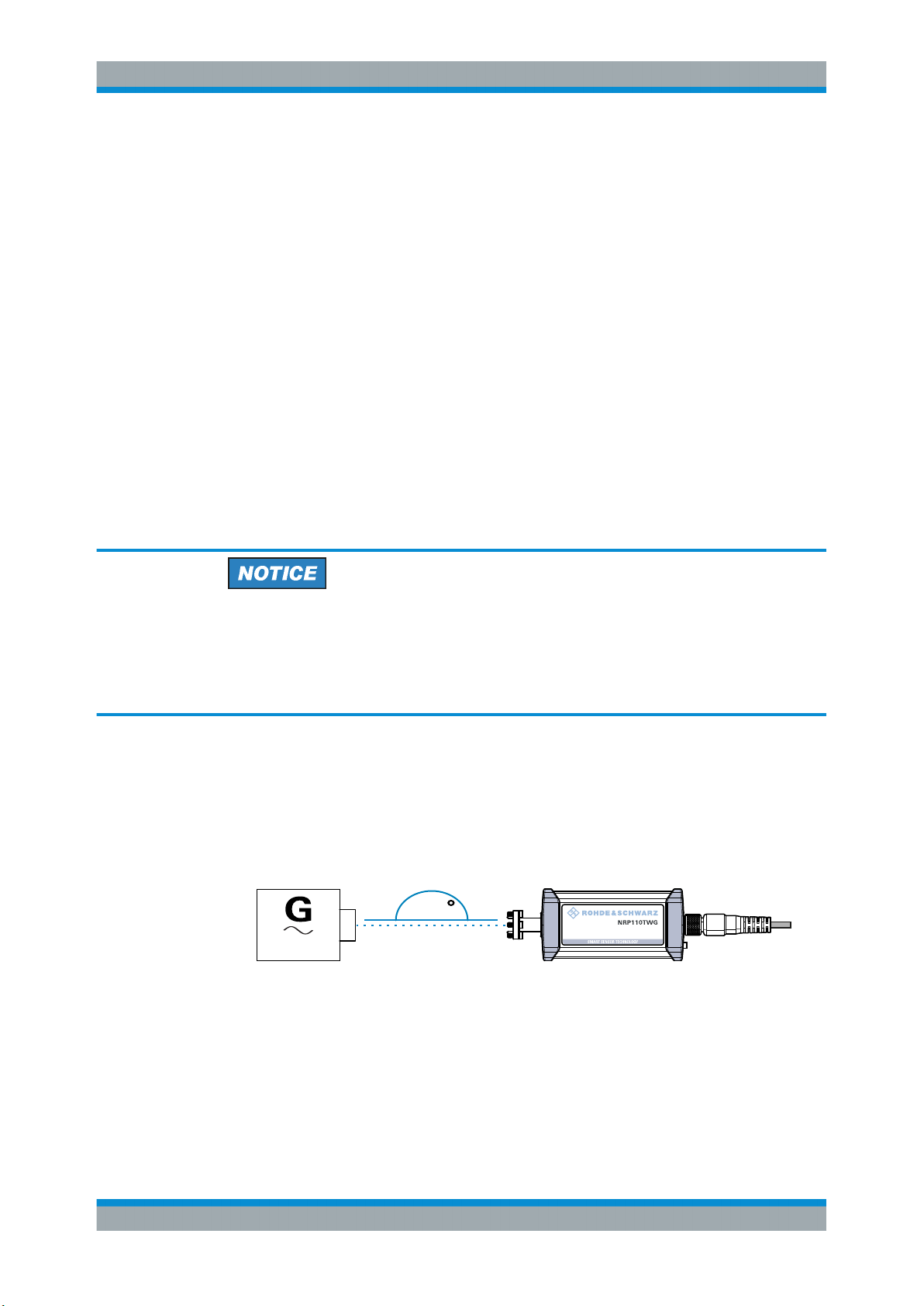
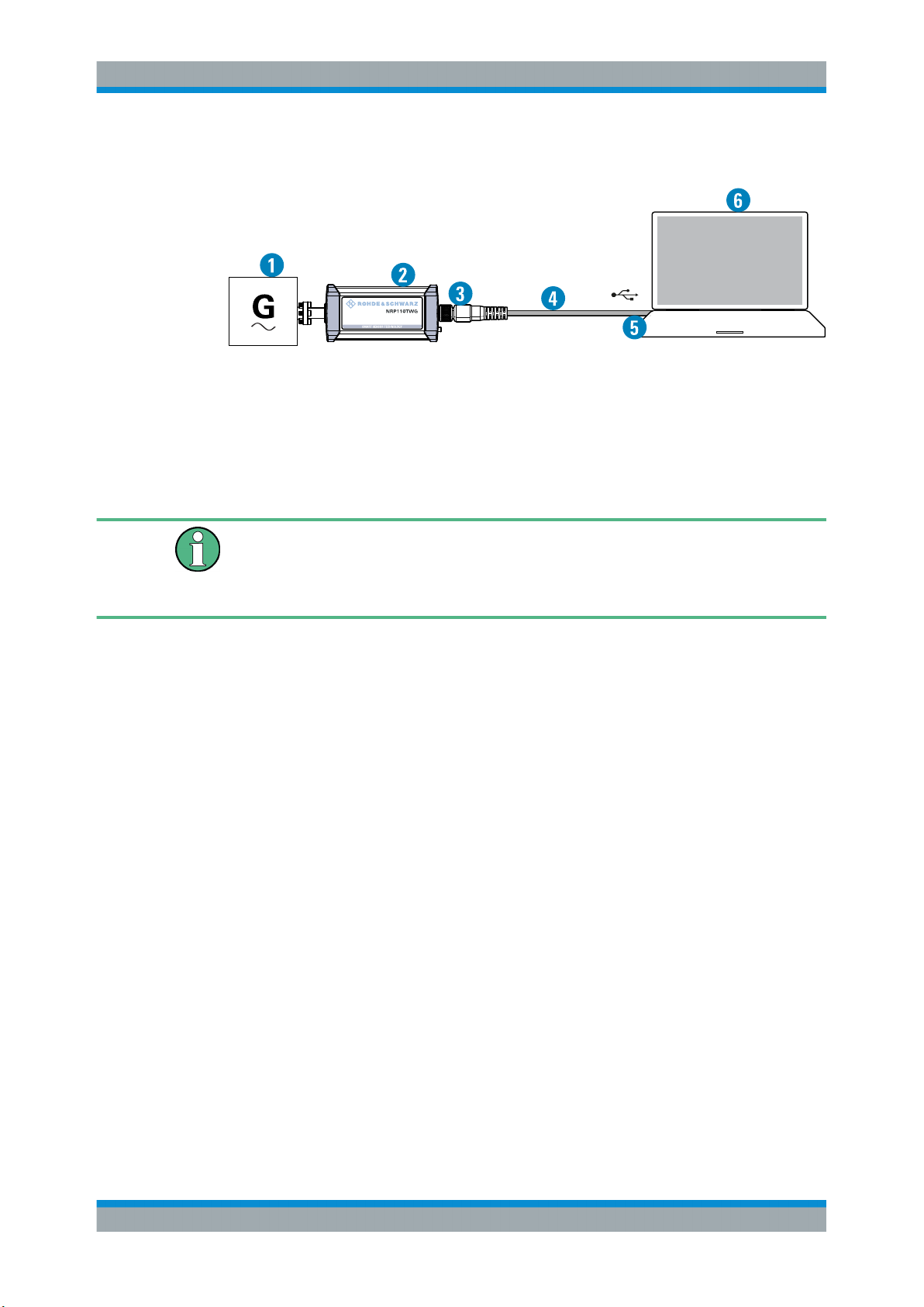
Figure 3-1: Setup with an R&S NRP‑ZKU cable
1 = Signal source
2 = R&S NRPxxTWG power sensor
3 = Host interface connector
4 = R&S NRP‑ZKU cable
5 = USB connector
6 = Computer with installed VISA driver or R&S NRP Toolkit
Incorrectly connecting/disconnecting the R&S NRPxxTWG power sensors can damage
the power sensors or lead to erroneous results.
Ensure that you connect/disconnect your power sensor as described in Chapter 3,
"Preparing for Use", on page 11.
1. Connect the cables as shown in Figure 3-1 :
a) Connect the R&S NRP‑ZKU cable to the power sensor.
b) Connect the R&S NRP‑ZKU cable to the computer.
c) Connect the power sensor to the signal source.
2. On the computer, start a software application to view the measurement results.
See Chapter 5, "Operating Concepts", on page 19.
3.5.1.2 R&S NRP‑Z5 Sensor Hub Setup
The R&S NRP‑Z5 sensor hub (high-speed USB 2.0) can host up to four R&S
NRPxxTWG power sensors and provides simultaneous external triggering to all connected sensors.
Required equipment
●
1 to 4 R&S NRPxxTWG power sensors
●
1 R&S NRP‑ZK6 cable per sensor
●
R&S NRP‑Z5 sensor hub with external power supply unit and USB cable
●
BNC cables to connect the trigger input and trigger output signals (optional)
14User Manual 1178.8371.02 ─ 04
Page 15
R&S®NRPxxTWG
Preparing for Use
Connecting to a Computer
Setup
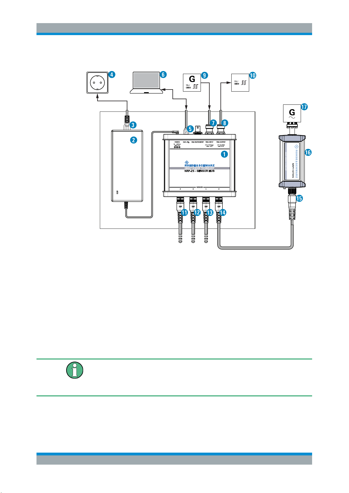
Figure 3-2: Setup with an R&S NRP-Z5 sensor hub
1 = R&S NRP‑Z5 sensor hub
2 = External power supply unit (supplied)
3 = Power cable (supplied)
4 = AC power supply
5 = USB cable (supplied)
6 = Computer with USB host interface
7, 8 = BNC cable (optional, not supplied)
9 = Trigger source (optional)
10 = Triggered device (optional)
11-14 = R&S NRP‑ZK6 cable
15 = Host interface connector
16 = R&S NRPxxTWG power sensor
17 = Signal source
Incorrectly connecting/disconnecting the R&S NRPxxTWG power sensors can damage
the power sensors or lead to erroneous results.
Ensure that you connect/disconnect your power sensor as described in Chapter 3,
"Preparing for Use", on page 11.
1. Connect the cables as shown in Figure 3-2:
a) Connect the R&S NRP‑ZK6 cable to the power sensor.
15User Manual 1178.8371.02 ─ 04
Page 16

R&S®NRPxxTWG
3.6 Connecting to a USB Host
Preparing for Use
Connecting to a USB Host
b) Connect the power sensors to the R&S NRP‑Z5 sensor hub. You can connect
up to four sensors.
c) Connect the R&S NRP‑Z5 to the computer.
d) Connect the power sensors to the signal source.
e) Connect the delivered external power supply unit to the R&S NRP‑Z5 and to an
AC supply connector.
f) Connect the trigger input of the R&S NRP‑Z5 with a BNC cable to the trigger
source (optional).
g) Connect the trigger output of the R&S NRP‑Z5 with a BNC cable to the trigger
device (optional).
2. On the computer, start a software application to view the measurement results.
See Chapter 5, "Operating Concepts", on page 19.
For connecting the power sensor to a USB host, use the host interface of the power
sensor. For details, see Chapter 4.3, "Host Interface", on page 18.
To connect a cable to the host interface of the power sensor
You can use an R&S NRP‑ZKU cable or R&S NRP‑ZK6 cable.
1. Insert the screw-lock cable connector into the host interface connector of the power
sensor.
2. Tighten the union nut manually.
To disconnect the host interface of the R&S NRPxxTWG power sensors
► Loosen the union nut of the screw-lock cable connector and remove the cable.
16User Manual 1178.8371.02 ─ 04
Page 17
R&S®NRPxxTWG
4 Power Sensor Tour
Power Sensor Tour
Trigger I/O Connector
This chapter provides an overview of the available connectors and LEDs of the power
sensor.
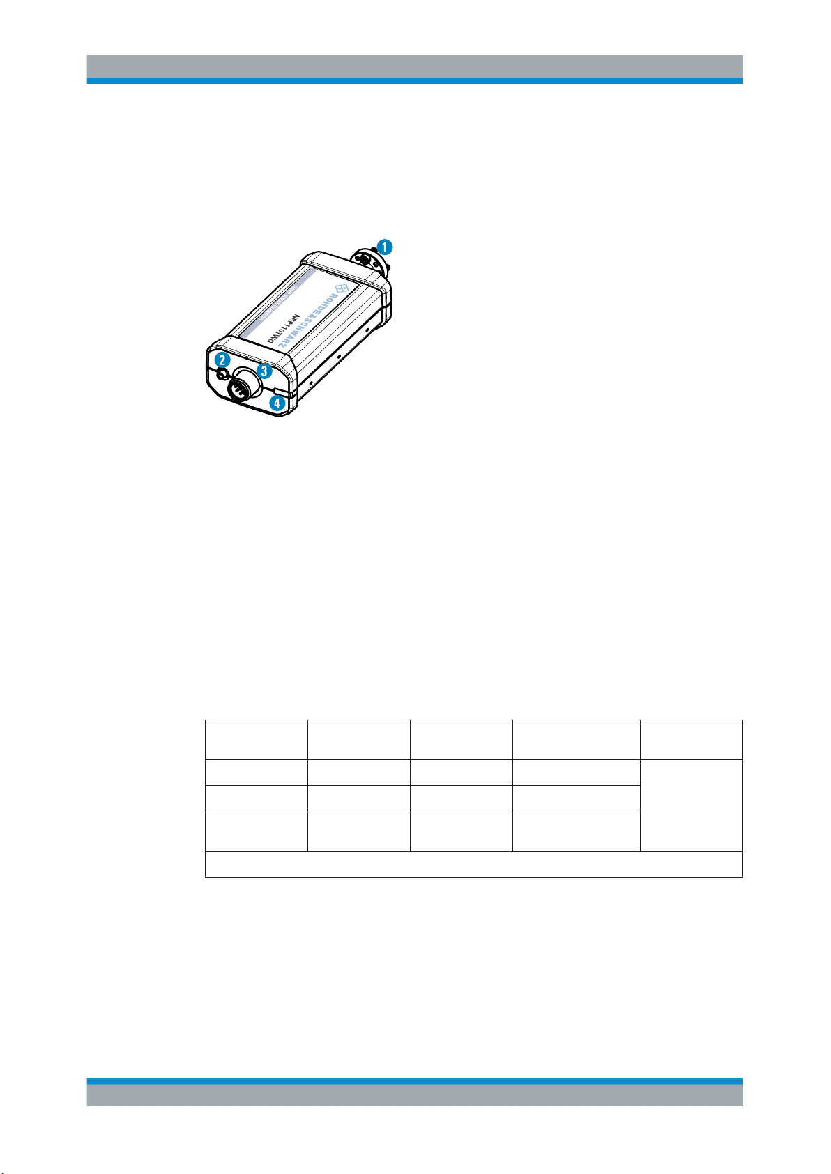
Figure 4-1: R&S NRPxxTWG power sensor (example)
1 = RF connector, see Chapter 4.1, "RF Connector", on page 17
2 = Trigger I/O connector, see Chapter 4.2, "Trigger I/O Connector", on page 17
3 = Host interface connector, see Chapter 4.3, "Host Interface", on page 18
4 = Status LED, see Chapter 4.4, "Status LED", on page 18
4.1 RF Connector
The RF connector is used for connecting the power sensor to a device under test
(DUT) or a signal generator.
For maximum measurement accuracy, tighten the RF connector using a torque wrench
with a nominal torque as specified in the following table.
Table 4-1: R&S
Power sensor Matching female
R&S NRP75TWG
R&S NRP90TWG
R&S
NRP110TWG
*It is recommended to use the torque wrench of the R&S tool with the part number 1175.2014.02.
NRPxxTWG RF connector characteristics
connector
WR-15 WR-15
WR-12 WR-12
WR-10 WR-10
4.2 Trigger I/O Connector
The trigger I/O is a connector of SMB type.
Male connector Frequency range Tightening tor-
que
50 GHz to 75 GHz
60 GHz to 90 GHz
75 GHz to 110 GHz
0.58 Nm (5'' lbs)
17User Manual 1178.8371.02 ─ 04
Page 18
R&S®NRPxxTWG
4.3 Host Interface
Power Sensor Tour
Status LED
It is used as an input for signals if the trigger source parameter is set to EXTernal2. It
is used as an output for trigger signals if the sensor is operated in the trigger master
mode.
Further information:
●
Chapter 7.5.2, "Triggering", on page 43
The host interface connector is used for establishing a connection between the power
sensors and a USB host or a supported Rohde & Schwarz instrument. For this purpose, an external cable is needed. Two types of cables are available:
●
R&S NRP‑ZKU cable with a USB connector, for connecting the power sensor to a
USB host device (R&S order number 1419.0658.xx).
●
R&S NRP‑ZK6 cable with a push-pull type connector, for connecting the power
sensor to a base unit, R&S NRX or R&S NRP2, or other Rohde & Schwarz products with the round connector (R&S order number 1419.0664.xx).
These cables can be obtained in different lengths up to 5 meters.
4.4 Status LED
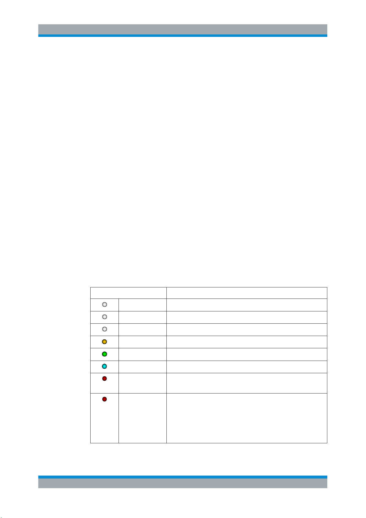
The status LED gives information about the state of the power sensor. The following
states are defined:
Indication State
White Idle state. The sensor performs no measurement and is ready for use.
Flashing white Firmware update is in progress
Slow flashing white Sanitizing in progress
Yellow Wait for trigger state
Green Measuring state
Turquoise blue Zeroing is in progress
Slow flashing red Static error
Fast flashing red Critical static error
You can query the error type with SYSTem:SERRor?.
You can query the error type with SYSTem:SERRor?.
Note: If this state occurs after a firmware update, the update was not
successful. Perform the firmware update again.
See also Chapter 10.3, "Problems during a Firmware Update",
on page 121.
18User Manual 1178.8371.02 ─ 04
Page 19
R&S®NRPxxTWG
5 Operating Concepts
5.1 R&S NRP Toolkit
Operating Concepts
R&S NRP Toolkit
For operating the power sensor, you can choose from various possibilities:
●
Chapter 5.2, "Remote Control", on page 22
●
Chapter 5.3, "R&S NRPV", on page 22
●
Chapter 5.4, "R&S Power Viewer", on page 24
●
Chapter 5.5, "R&S Power Viewer Mobile", on page 26
●
Chapter 5.6, "R&S NRX", on page 26
●
Chapter 5.7, "R&S NRP2", on page 28
Before you start using the power sensor, it is recommended to install the R&S NRP
Toolkit.
The R&S NRP Toolkit is the basic software package that supplies low-level drivers and
tools for all power sensors. The components of the R&S NRP Toolkit depend on the
operating system.
5.1.1 Versions and Downloads
The R&S NRP Toolkit is available for the Microsoft Windows operating systems listed
under Chapter 5.1.2, "System Requirements", on page 19, Linux distributions and
MacOSX. Several R&S NRP Toolkit versions are available on your documentation CDROM.
The latest version for Windows is available at www.rohde-schwarz.com/software/nrp-
toolkit.
To obtain an R&S NRP Toolkit for an operating system other than Microsoft Windows,
contact the Rohde & Schwarz customer support: customersupport@rohde-
schwarz.com
5.1.2 System Requirements
Hardware requirements:
●
Desktop computer or laptop, or an Intel-based Apple Mac
Supported operating systems:
●
Microsoft Windows versions
– Microsoft Windows Vista 32/64-bit
– Microsoft Windows 7 32/64-bit
19User Manual 1178.8371.02 ─ 04
Page 20
R&S®NRPxxTWG
5.1.3 R&S NRP Toolkit for Windows
Operating Concepts
R&S NRP Toolkit
– Microsoft Windows 8/ 8.1 32/64-bit
– Microsoft Windows 10 32/64-bit
●
For information on other operating systems, see Chapter 5.1.1, "Versions and
Downloads", on page 19.
The R&S NRP Toolkit installer for Windows-based systems contains the components
described in the release notes available at www.rohde-schwarz.com/software/nrp-tool-
kit.
Installing on a computer
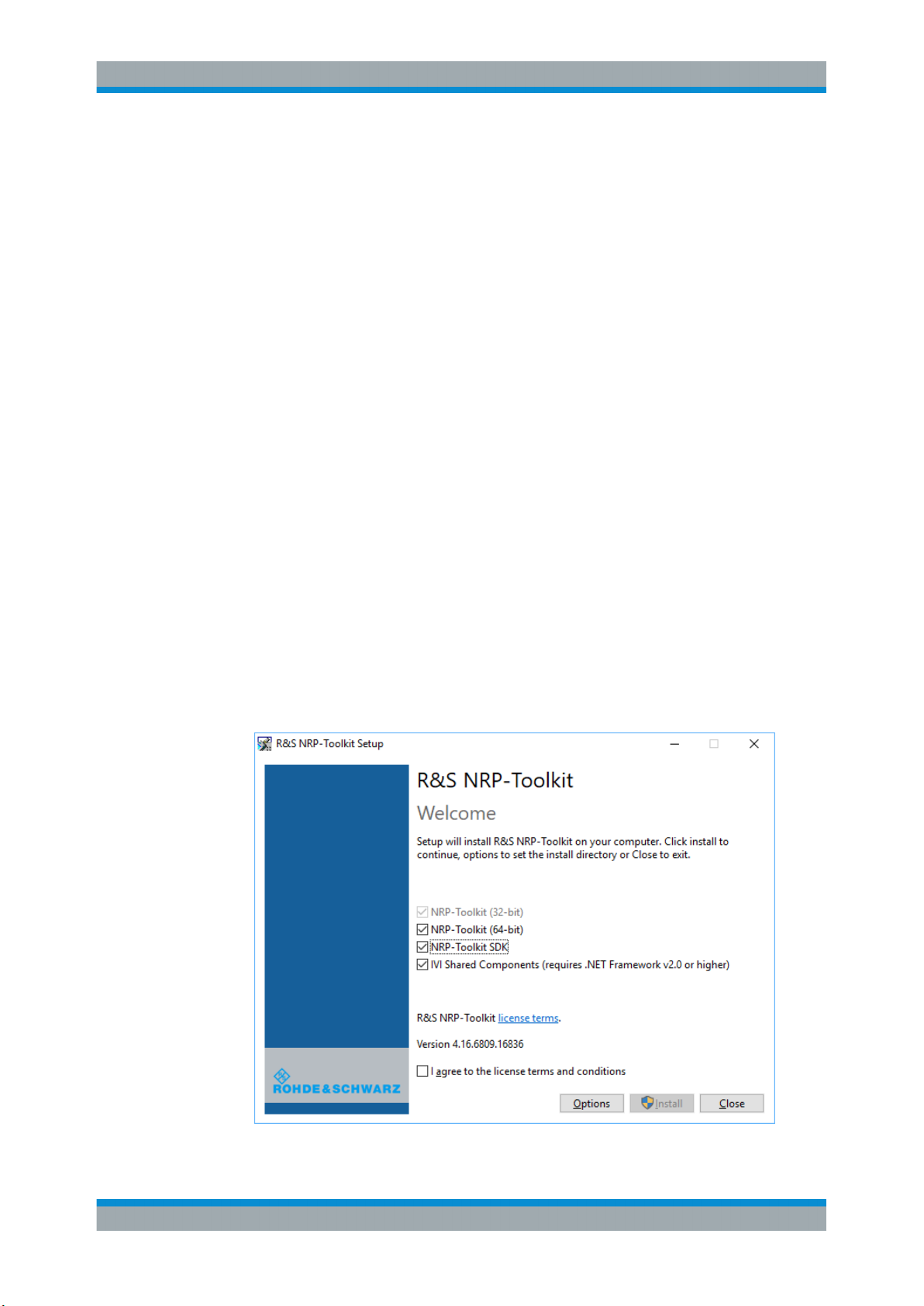
1. Start the R&S NRP Toolkit installer on the Windows-based computer.
In the "NRP-Toolkit Setup" dialog, the correct R&S NRP Toolkit version for your
operating system, 32-bit or 64-bit, is already selected.
2. Enable the components you want to install.
● "NRP-Toolkit (SDK)"
The software development kit (SDK) provides programming examples for the
R&S power sensors.
See Chapter 8, "Performing Measurement Tasks - Programming Examples",
on page 97.
● "IVI Shared Components"
Installs the USBTMC driver. Enabled by default because the installation is recommended.
See also Table 9-1.
20User Manual 1178.8371.02 ─ 04
Page 21

R&S®NRPxxTWG
5.1.3.1 Components of the R&S NRP Toolkit
Operating Concepts
R&S NRP Toolkit
3. Accept the license terms to continue with the installation.
4. Click "Next" and complete the installation process.
Access: "Start" > "NRP-Toolkit"
The following tools are part of the R&S NRP Toolkit for Windows.
Configure Network Sensor
Useful if you have troubles establishing a LAN connection with an R&S NRP LAN
power sensor. The tool provides the following functions:
●
Configuring the network settings by (temporary) connecting the selected sensor to
the computer using USB.
●
Discovering the sensors that have been configured via the Zeroconf (APIA) protocol.
The tool comes with a guide (PDF) that is also available in the "Start" menu. The guide
explains the network setup.
Firmware Update
You can use the Firmware Update for NRP Family program to load new firmware for
the power sensors.
See Chapter 6, "Firmware Update", on page 31.
NRP Version Display
Displays version information of all installed, power measurement-relevant software
packages.
R&S NRP‑Z Uncertainty Calculator
Determines the expanded measurement uncertainty. The tool comes with a manual
(PDF) that is also available in the "Start" menu.
S-Parameter Update Multi
Helps loading an S-parameter table into the power sensor.
See Chapter 7.8.3.5, "Using the S-Parameters Tool", on page 69.
Terminal
Low-level communication program for sending commands to the power sensor.
21User Manual 1178.8371.02 ─ 04
Page 22
R&S®NRPxxTWG
5.2 Remote Control
5.3 R&S NRPV
Operating Concepts
R&S NRPV
You can remote control the R&S NRPxxTWG easily. The change to remote control
occurs "on the fly" and has no influence on the manual operation.
Further information:
●
Chapter 7, "Remote Control Commands", on page 35
●
Chapter 9, "Remote Control Basics", on page 100
●
Chapter 9.1, "Remote Control Interfaces and Protocols", on page 100
●
Chapter 3.5, "Connecting to a Computer", on page 13
The R&S NRPV enables you to measure power in all available measurement modes.
Also, you can use up to four power sensors simultaneously.
The R&S NRPV is provided on your documentation CD-ROM and on the Rohde &
Schwarz website as a separate standalone installation package.
Required equipment
●
R&S NRPxxTWG power sensor
●
R&S NRP‑ZKU cable or an R&S NRP‑Z5 sensor hub and an R&S NRP‑ZK6 cable
to connect the sensor to the computer
●
Windows computer with installed:
– R&S NRP Toolkit V 4.17 or higher
– R&S NRPV version 3.2 or higher (refer to the operating manual of the R&S
NRPV for a description of the installation process)
Setup
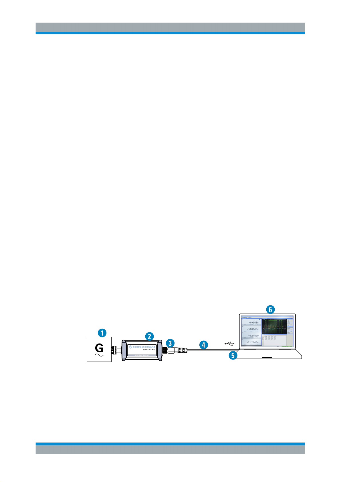
Figure 5-1: Setup with an R&S NRPV
1 = Signal source
2 = R&S NRPxxTWG power sensor
3 = Host interface connector
4 = R&S NRP‑ZKU cable
5 = USB connector
6 = Computer with installed R&S NRPV
22User Manual 1178.8371.02 ─ 04
Page 23
R&S®NRPxxTWG
Operating Concepts
R&S NRPV
Incorrectly connecting/disconnecting the R&S NRPxxTWG power sensors can damage
the power sensors or lead to erroneous results.
Ensure that you connect/disconnect your power sensor as described in Chapter 3,
"Preparing for Use", on page 11.
Starting a measurement
1. Connect the power sensor to the computer as shown in Figure 5-1.
For a detailed description, refer to Chapter 3.5.1.1, "Simple USB Connection",
on page 13.
2. Start the R&S NRPV.
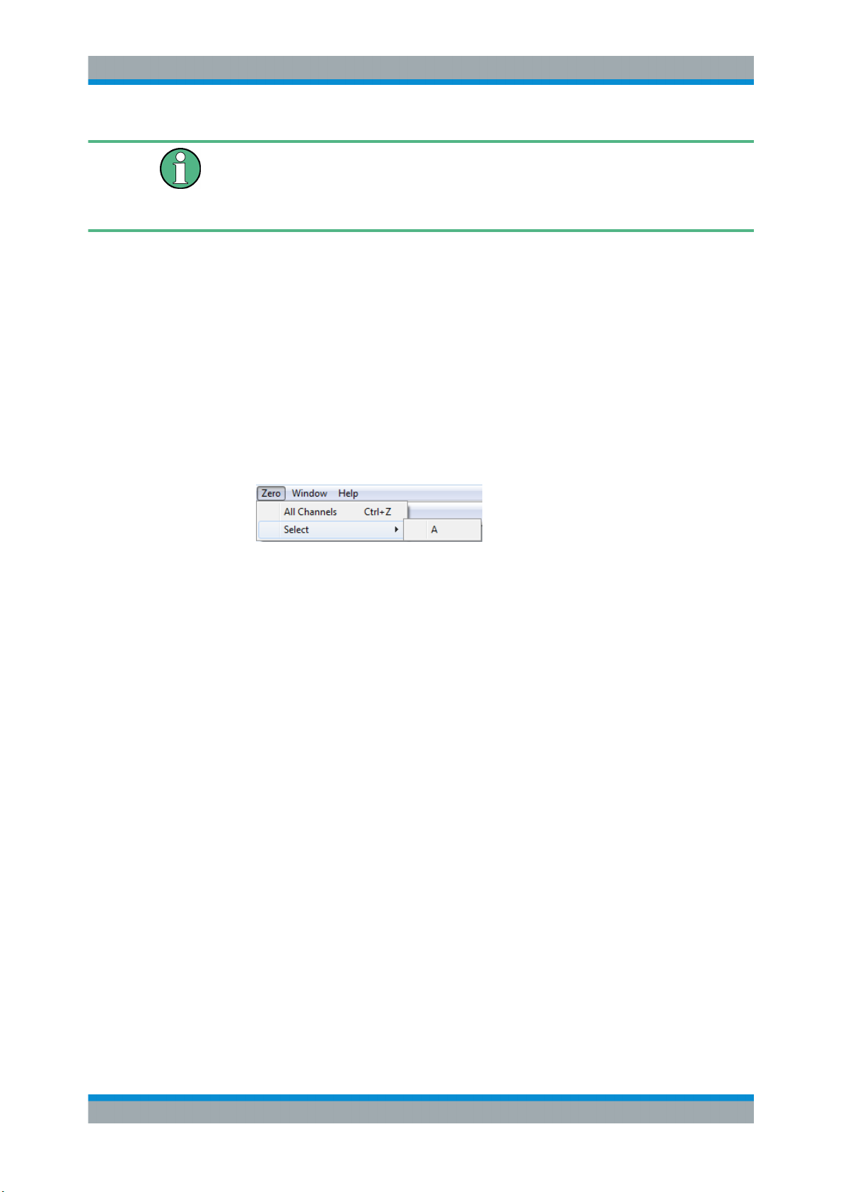
3. Execute zeroing:
Note: Turn off all measurement signals before zeroing. An active measurement
signal during zeroing causes an error.
a) Switch off the measurement signal.
b) Select "Zero > Select > A" (channel short name).
Zeroing takes several seconds. During zeroing, a message shows the progress. After completion, the message reports either success or an error ("Success" / "Failed").
4. Switch on the test signal of the signal source.
5. To start a continuous measurement, select "Measure > Continuous".
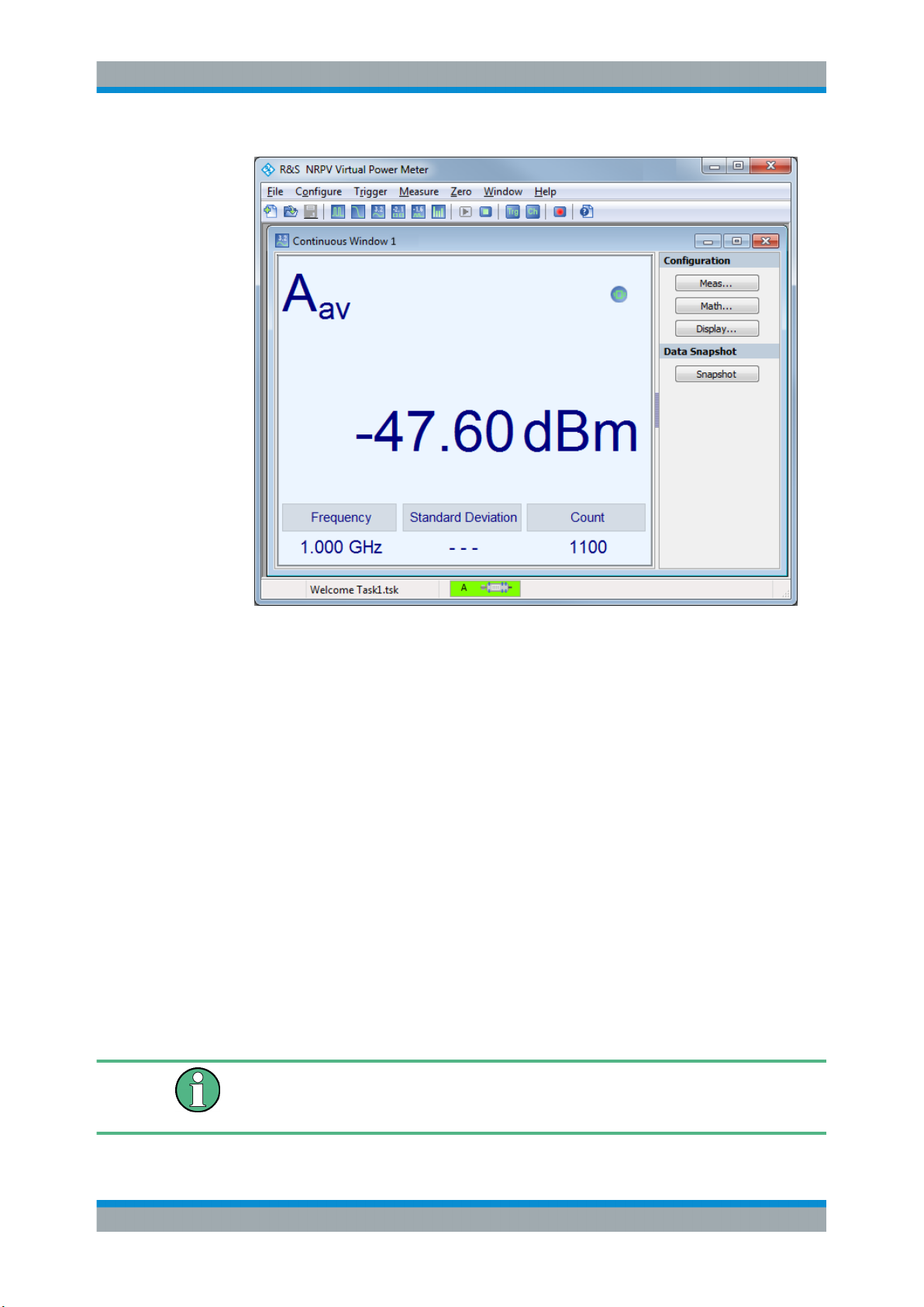
The "Continuous" measurement window appears. It shows the measurement
results numerically, and the control panel for accessing further dialogs with parameters for measurement, evaluation and display.
23User Manual 1178.8371.02 ─ 04
Page 24
R&S®NRPxxTWG
Operating Concepts
R&S Power Viewer
For a detailed description on how to measure in this setup, refer to the operating manual of the R&S NRPV.
5.4 R&S Power Viewer
The R&S Power Viewer is software that simplifies many measurement tasks. It is provided on your documentation CD-ROM and on the Rohde & Schwarz website as a separate standalone installation package.
Required equipment
●
R&S NRPxxTWG power sensor
●
R&S NRP‑ZKU cable or an R&S NRP‑Z5 sensor hub and an R&S NRP‑ZK6 cable
to connect the sensor to the computer
●
Computer with installed:
– R&S NRP Toolkit V 4.17 or higher
– R&S Power Viewer version 9.2 or higher (refer to the operating manual of the
R&S Power Viewer for a description of the installation process)
If you want to use an android device like a tablet or a smartphone, use the R&S Power
Viewer Mobile. For details, see Chapter 5.5, "R&S Power Viewer Mobile",
on page 26.
24User Manual 1178.8371.02 ─ 04
Page 25
R&S®NRPxxTWG
Operating Concepts
R&S Power Viewer
Setup
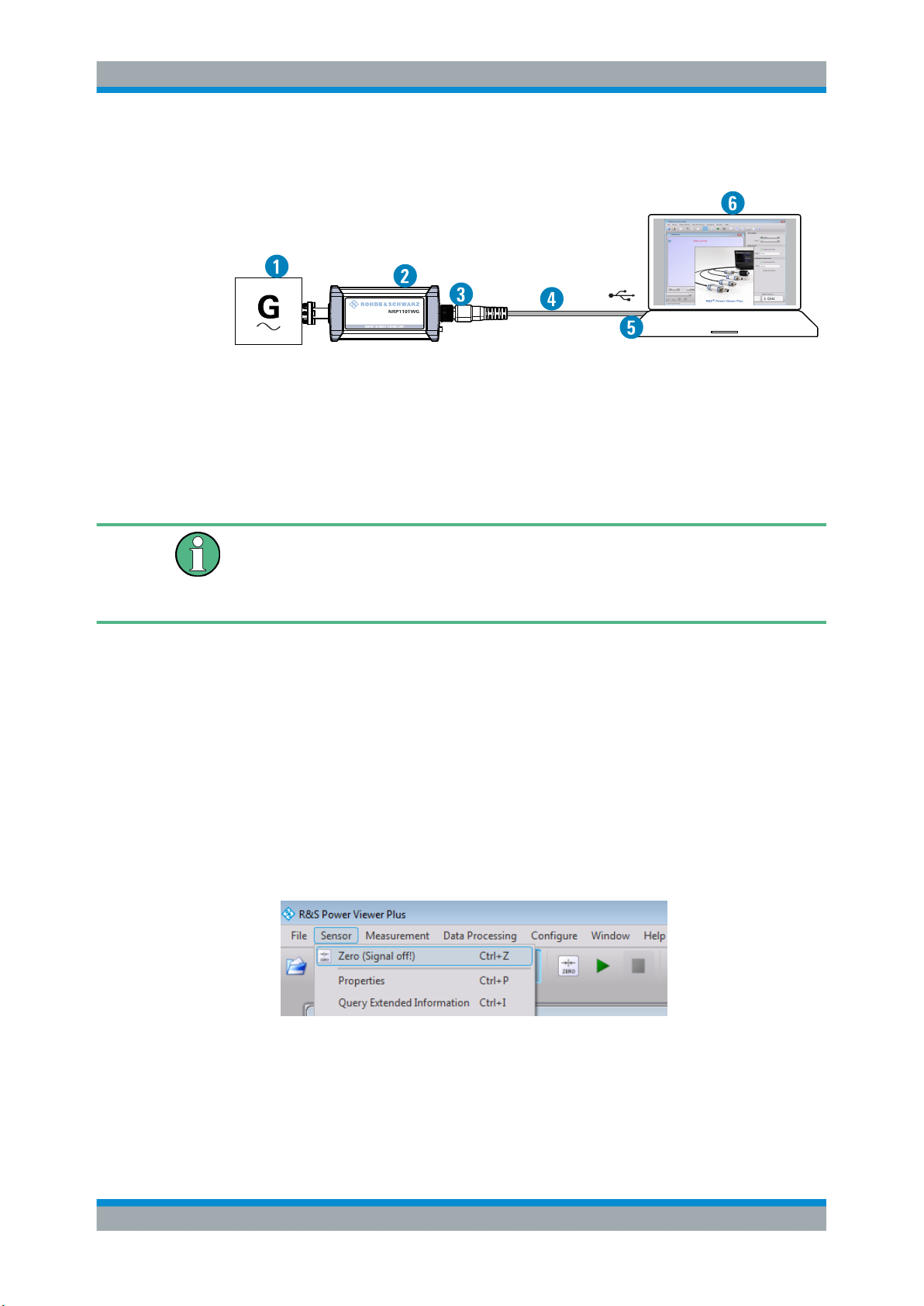
Figure 5-2: Setup with the R&S Power Viewer
1 = Signal source
2 = R&S NRPxxTWG power sensor
3 = Host interface connector
4 = R&S NRP‑ZKU cable
5 = USB connector
6 = Computer with installed R&S Power Viewer
Incorrectly connecting/disconnecting the R&S NRPxxTWG power sensors can damage
the power sensors or lead to erroneous results.
Ensure that you connect/disconnect your power sensor as described in Chapter 3,
"Preparing for Use", on page 11.
Starting a measurement
1. Connect the cables as shown in Figure 5-2.
For a detailed description, refer to Chapter 3.5.1.1, "Simple USB Connection",
on page 13.
2. Start the R&S Power Viewer.
3. Execute zeroing:
Note: Turn off all measurement power signals before zeroing. An active measurement signal during zeroing causes an error.
a) Switch off the measurement signal.
b) Select "Sensor > Zero (Signal off) ".
4. Switch on the test signal of the signal source.
5. For a continuous average measurement, select "Measurement > Continuous".
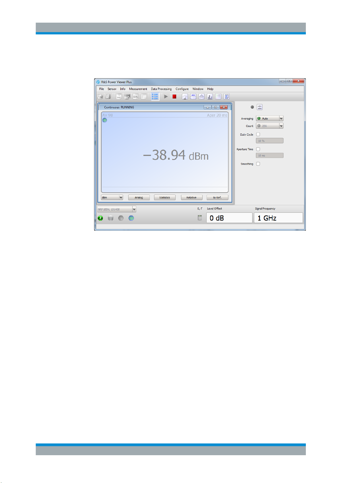
The "Continuous" measurement window appears. It shows the measurement
results numerically and some parameters that can be configured.
25User Manual 1178.8371.02 ─ 04
Page 26
R&S®NRPxxTWG
Operating Concepts
R&S NRX
6. To start the measurement press "Measurement > Start".
The measurement result is shown in the "Continuous" measurement window.
For a detailed description of how to measure in this setup, refer to the operating manual of your R&S Power Viewer. The manual is installed automatically during the installation of the R&S Power Viewer.
5.5 R&S Power Viewer Mobile
The R&S Power Viewer Mobile extends the functionality of the R&S Power Viewer to
Android-based devices, such as a smartphone and tablets.
You can download the R&S Power Viewer Mobile free of charge from the Google Play
Store.
The 1MA215 "Using R&S®NRP Series Power Sensors with AndroidTM Handheld Devices" application note gives a detailed description on installation and features of the
R&S Power Viewer Mobile. The application note is provided on the documentation CDROM.
5.6 R&S NRX
In a measurement, the R&S NRX uses all sensor-dependent measurement functions
and displays the results. Thus, you can configure both the measurement and the
power sensor.
26User Manual 1178.8371.02 ─ 04
Page 27
R&S®NRPxxTWG
Required equipment
●
R&S NRPxxTWG power sensor
●
R&S NRP‑ZK8 to connect the sensor to the R&S NRX
●
R&S NRX
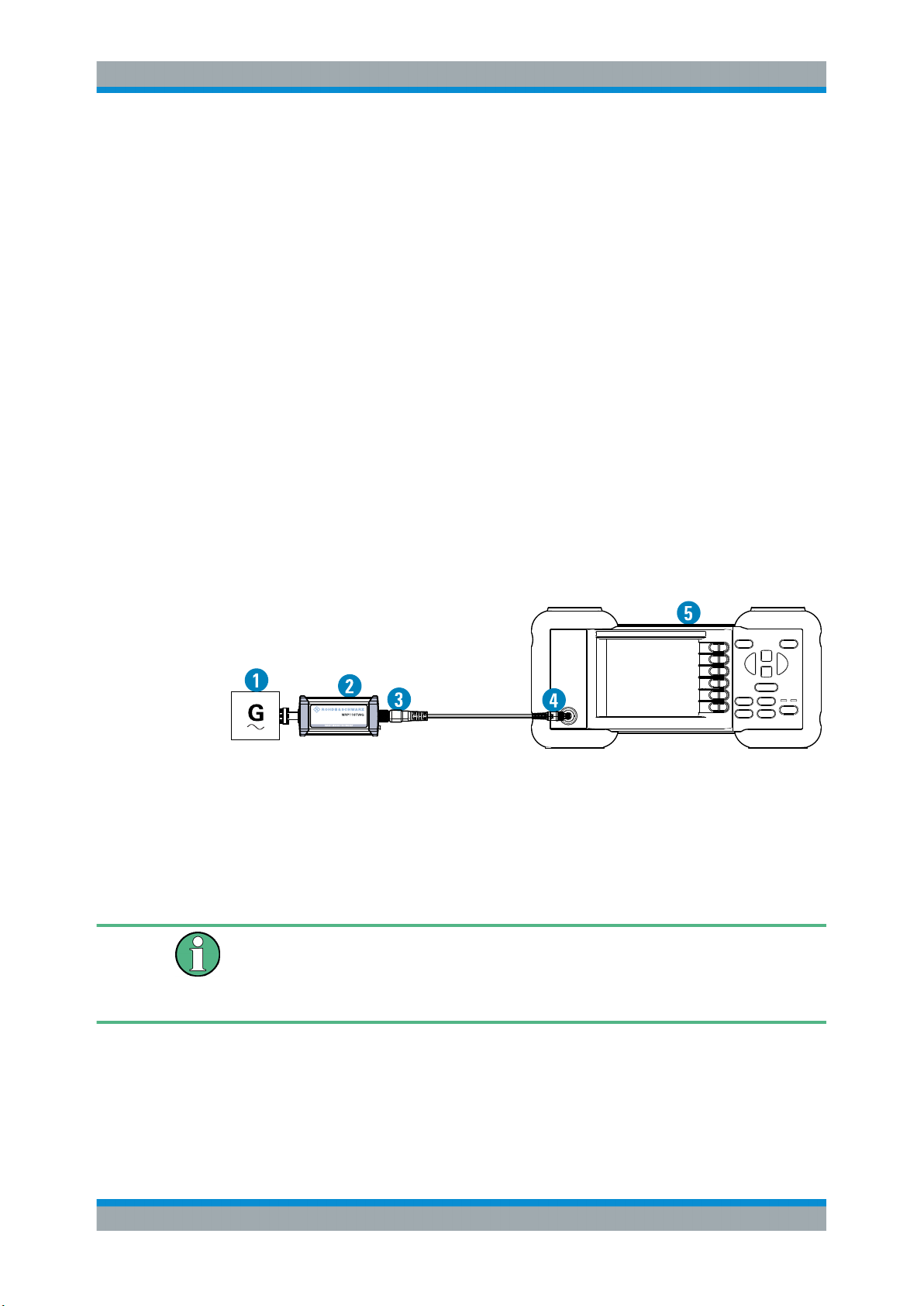
Setup
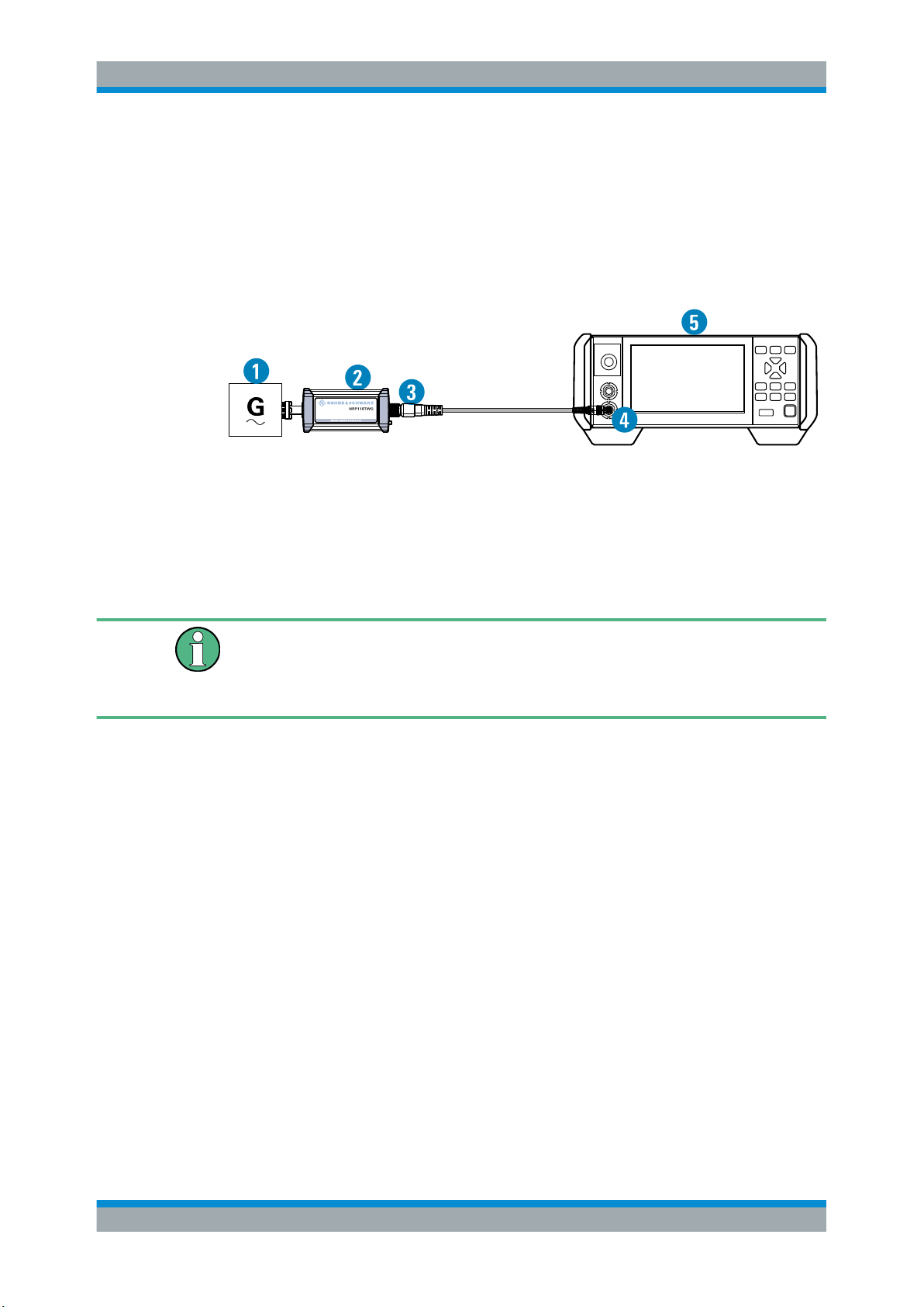
Figure 5-3: Setup with an R&S NRX base unit
1 = Signal source
2 = R&S NRPxxTWG power sensor
3 = Host interface connector
4 = R&S NRP‑ZK8
5 = Sensor input connector of the R&S NRX
6 = R&S NRX base unit
Operating Concepts
R&S NRX
Incorrectly connecting/disconnecting the R&S NRPxxTWG power sensors can damage
the power sensors or lead to erroneous results.
Ensure that you connect/disconnect your power sensor as described in Chapter 3,
"Preparing for Use", on page 11.
Starting a measurement
1. Preset the R&S NRX and the connected R&S power sensors.
a) Press the [Preset] key.
b) Tap "Preset".
All parameters are set to their defaults.
2. If measuring in zero-IF mode (RBW > 40 MHz), consider to zero the power sensor:
Note: Turn off all measurement signals before zeroing. An active measurement
signal during zeroing causes an error.
a) Switch off the power of the signal source.
b) Press the [Zero] key of the R&S NRX.
c) Tap "Zero All Sensors".
3. Configure the measurement.
a) In the "Measurement Settings" dialog, select the "Measurement Type", for
example "Continuous Average".
b) Tap "Quick Setup" > "Auto Set".
4. Switch on the signal source.
27User Manual 1178.8371.02 ─ 04
Page 28
R&S®NRPxxTWG
5.7 R&S NRP2
Operating Concepts
R&S NRP2
The measurement starts, and the result is displayed in dBm.
5. If necessary, perform further settings.
For a detailed description of how to measure in this setup, refer to the user manual of
the R&S NRX.
With the R&S NRPxxTWG power sensors and an R&S NRP2, you can measure power
with up to four power sensors simultaneously. All sensor-dependent measurement
functions can be used and the results can be displayed in parallel.
Required equipment
●
R&S NRPxxTWG power sensor
●
R&S NRP‑ZK6 cable to connect the sensor to the R&S NRP2
●
R&S NRP2 base unit with FW version 7.11 or higher
Setup
Figure 5-4: Setup with an R&S NRP2 base unit
1 = Signal source
2 = R&S NRPxxTWG power sensor
3 = Host interface connector
4 = R&S NRP‑ZK6 cable
5 = Sensor input connector of the R&S NRP2
6 = R&S NRP2 base unit
Incorrectly connecting/disconnecting the R&S NRPxxTWG power sensors can damage
the power sensors or lead to erroneous results.
Ensure that you connect/disconnect your power sensor as described in Chapter 3,
"Preparing for Use", on page 11.
Starting a measurement
1. Connect the cables as shown in Figure 5-4:
a) Connect the R&S NRP‑ZK6 cable to the host interface connector of the sensor.
28User Manual 1178.8371.02 ─ 04
Page 29
R&S®NRPxxTWG
Operating Concepts
R&S NRP2
b) Connect the R&S NRP‑ZK6 cable to a sensor input connector of the R&S
NRP2.
c) Connect the [RF] connector of the power sensor to the signal source.
2. Preset the R&S NRP2.
a) Press the [(PRE)SET] hardkey.
The "File" menu appears.
b) Press the [(PRE)SET] hardkey again or press the "Preset" softkey.
All parameters are set to their defaults, even when in inactive operating modes.
3. Execute zeroing:
Note: Turn off all measurement signals before zeroing. An active measurement
signal during zeroing causes an error.
a) Switch off the power of the signal source.
b) Press the [ZERO] hardkey of the R&S NRP2.
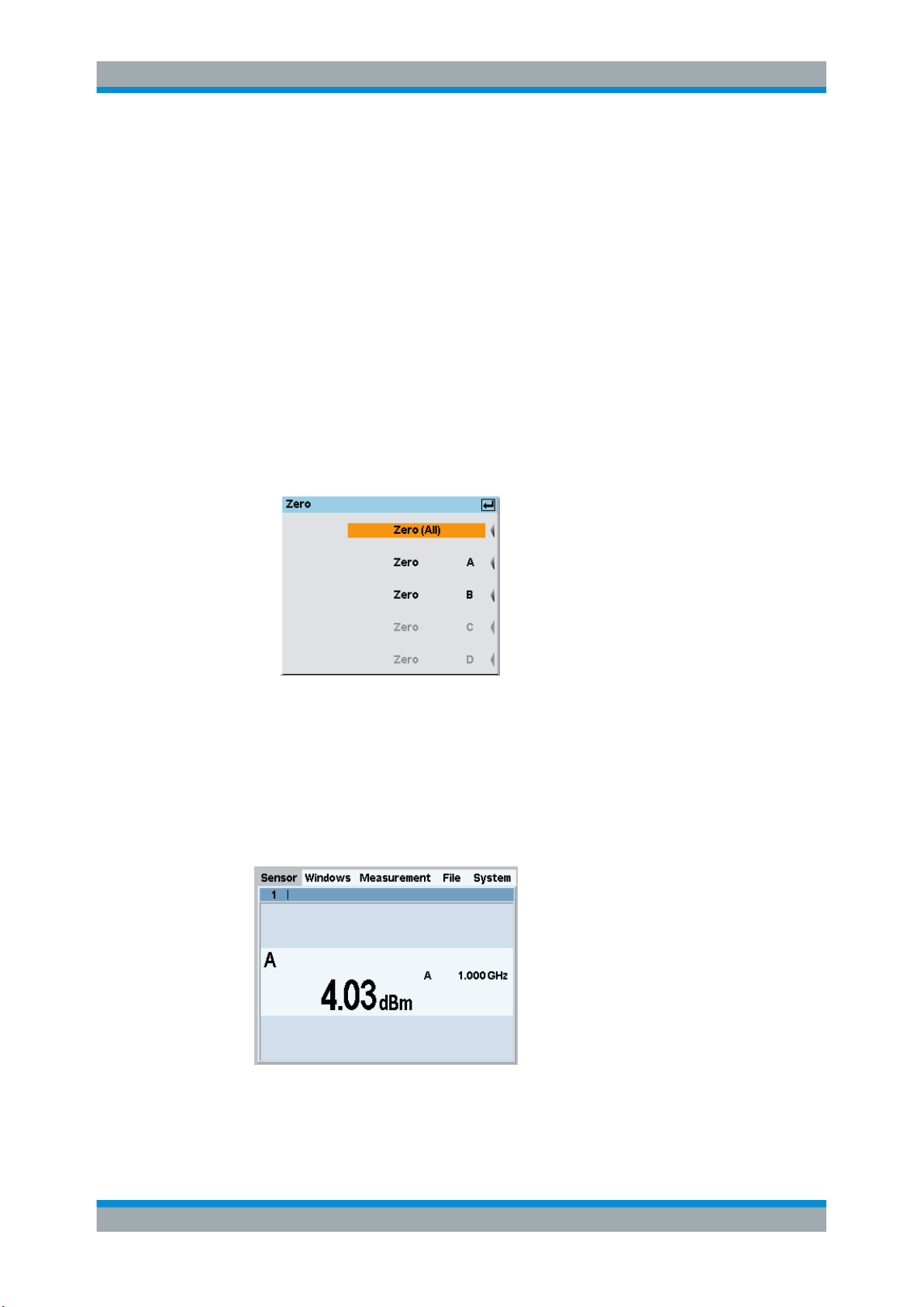
The "Zero" dialog box is displayed.
c) Press the [ZERO] hardkey again to perform zeroing of all connected sensor
channels ("Zero (All)") or press the appropriate softkey to select a specific sensor for zeroing.
4. Press the [FREQ] hardkey and enter the carrier frequency of the applied signal if
the specified measurement accuracy is to be reached.
5. Switch on the signal source.
The result window indicates the result (in dBm) obtained with sensor A.
6. If necessary, perform further settings.
29User Manual 1178.8371.02 ─ 04
Page 30

R&S®NRPxxTWG
Operating Concepts
R&S NRP2
For a detailed description of how to measure in this setup, refer to the operating manual of your R&S NRP2.
30User Manual 1178.8371.02 ─ 04
Page 31
R&S®NRPxxTWG
6 Firmware Update
6.1 Hardware and Software Requirements
Firmware Update
Updating the Firmware
● Hardware and Software Requirements...................................................................31
● Updating the Firmware............................................................................................31
For performing a firmware update, the system requirements are as follows:
●
Connectors and cables for establishing a connection to the computer
See Chapter 3.5, "Connecting to a Computer", on page 13.
●
Rohde & Schwarz update file (*.rsu) for the power sensor
Download the most recent firmware version from the Rohde & Schwarz homepage
on the Internet, since the CD-ROM accompanying the power sensor contains the
firmware dating from the time of delivery. The latest firmware update files are available at:
www.rohde-schwarz.com/en/firmware/nrp_twg/
If the *.rsu file is packed in a *.zip archive, extract it before updating.
●
If you use the Firmware Update for NRP Family program, further requirements are
essential. See "Checking the prerequisites" on page 32.
6.2 Updating the Firmware
Risk of faulty firmware
Disconnecting the power supply while an update is in progress can lead to missing or
faulty firmware.
Take special care not to disconnect the power supply while the update is in progress.
Interrupting the power supply during the firmware update most likely leads to an unusable power sensor that needs to be sent in for maintenance.
You can use the following methods to update the firmware installed on the power sensor:
● Using the Firmware Update for NRP Family Program............................................ 31
● Using Remote Control.............................................................................................33
6.2.1 Using the Firmware Update for NRP Family Program
Firmware Update for NRP Family is part of the R&S NRP Toolkit. See also Chap-
ter 5.1, "R&S NRP Toolkit", on page 19.
31User Manual 1178.8371.02 ─ 04
Page 32
R&S®NRPxxTWG
Firmware Update
Updating the Firmware
Checking the prerequisites
1. Ensure that a recent VISA software is installed on the computer. You can perform a
firmware update with Firmware Update for NRP Family only if the power sensor is
recognized as a VISA device.
2. Ensure that the R&S NRP Toolkit for Windows is installed on the computer. See
Chapter 5.1, "R&S NRP Toolkit", on page 19.
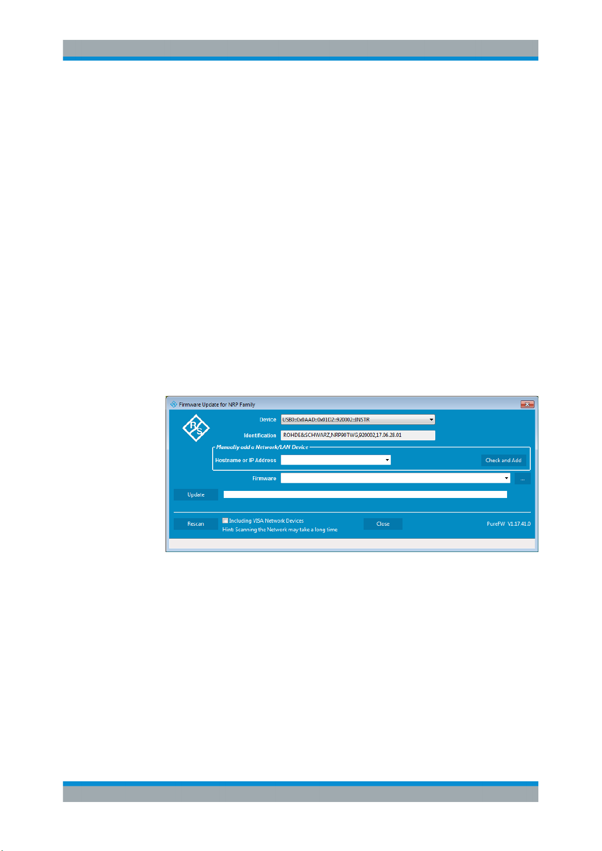
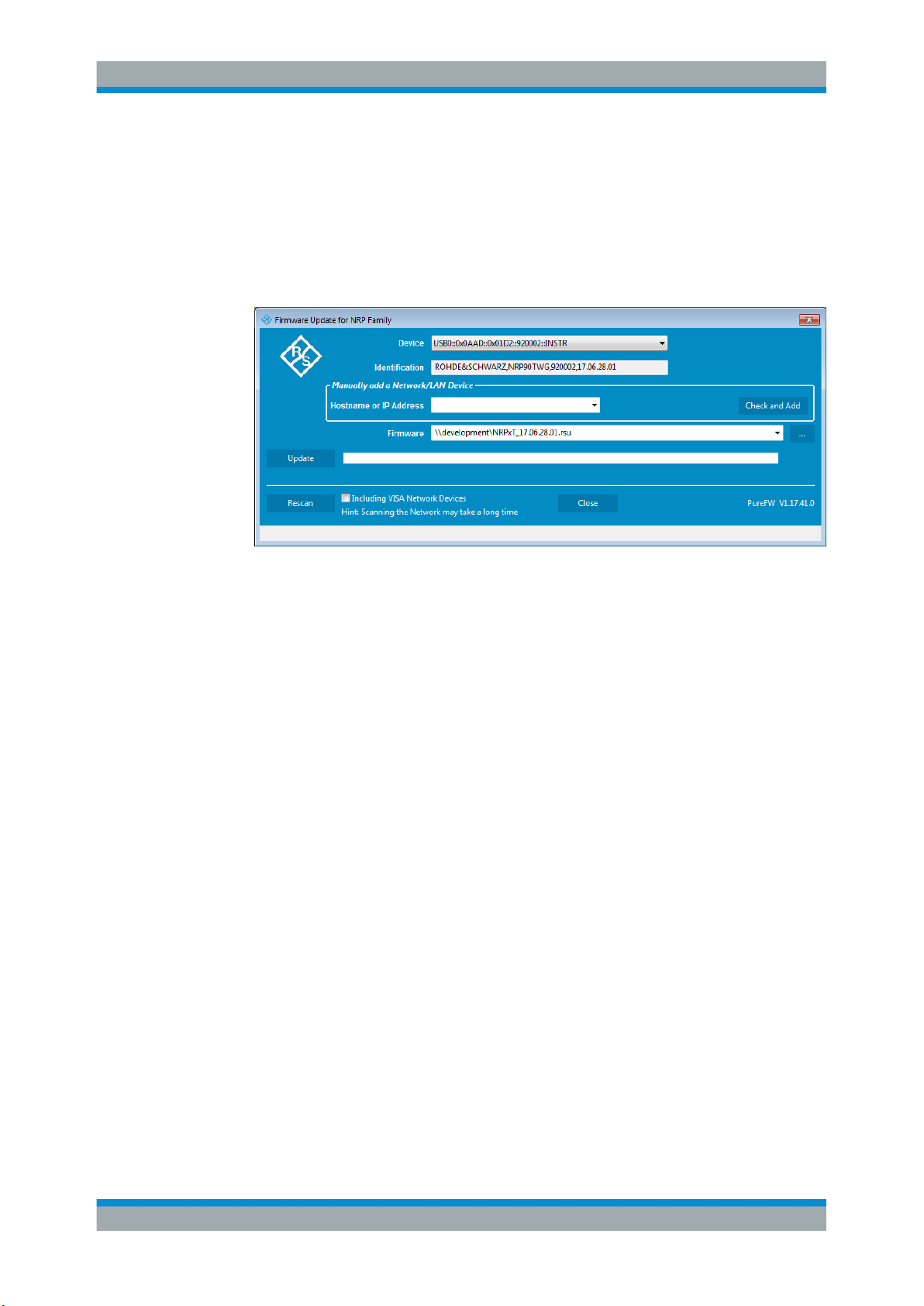
Firmware Update for NRP Family
A firmware update can take up to 5 minutes. Ensure that the update is not interrupted.
1. Check the prerequisites, see "Checking the prerequisites" on page 32.
2. Connect the power sensor to the computer as described in Chapter 3.5, "Connect-
ing to a Computer", on page 13.
3. Start the Firmware Update for NRP Family program:
"Start" menu > "NRP-Toolkit" > "Firmware Update".
The program automatically starts scanning for Rohde & Schwarz power sensors
connected via USB.
When the scan is completed, all recognized power sensors are listed under
"Device".
4. If the sensor you want to update is not listed, perform one of the following actions:
a) Click "Rescan" to search for attached sensors.
b) Check whether all necessary drivers are installed on the computer.
For example, if the VISA library is not installed on the computer, no VISA power
sensor is accessible.
See also "Troubleshooting" on page 33.
5. Under "Device", select the sensor you want to update.
Note: The "Hostname or IP Address" field is not used during this procedure. There-
fore, leave it empty.
6. Under "Firmware", enter the full path and filename of the update file, or press the
browse button next to the field. New firmware for the Rohde & Schwarz power sensors generally has an *.rsu (Rohde & Schwarz update) extension.
32User Manual 1178.8371.02 ─ 04
Page 33
R&S®NRPxxTWG
Firmware Update
Updating the Firmware
7. Click "Update".
During the update process, a progress bar is displayed. The update sequence can
take a couple of minutes, depending on the sensor model and the size of the
selected file.
8. Check if the update was successful. The firmware version in the "Identification"
field must match the version you selected in the "Firmware" field.
Troubleshooting
You do not find the sensor in the list of sensors provided by Firmware Update for NRP
Family.
The driver assigned to the sensor is the legacy driver.
► Install a recent VISA software.
The power sensor is highlighted by a yellow exclamation mark in the Windows device
manager.
Windows tries in vain to find a USB driver for the power sensor.
► Install a recent VISA software.
For further information, see Chapter 10.3, "Problems during a Firmware Update",
on page 121.
6.2.2 Using Remote Control
If you want to integrate a firmware update function in an application, use SYSTem:
FWUPdate on page 87.
33User Manual 1178.8371.02 ─ 04
Page 34

R&S®NRPxxTWG
Firmware Update
Updating the Firmware
Example:
You want to update your NRP110TWG with the nrp75twg_FW_15.02.12.01.rsu
file. This file has a size of 10242884 bytes.
To send the file to the sensor for updating the firmware, your application has to assemble a memory block containing:
SYST:FWUP <block_data>
The <block_data> are definite length arbitrary block data as described in SYSTem:
FWUPdate on page 87.
The size of the file is 10242884. This number has 8 digits. Thus, the <block_data>
consist of the following:
●
#
●
8
How many digits follow to specify the file size.
●
10242884
Number that specifies the file size.
●
<file_contents>
Contents of the *.rsu file, byte-by-byte
●
0x0a
Delimiter
In this example, you write exactly 10242905 bytes to the power sensor, for example by
using a 'viWrite()' function.
The 10242905 bytes result from the values of the list above:
9 + 1 + 1 + 1 + 8 + 10242884 + 1
In a (pseudo) string notation, the memory block looks as follows:
SYST:FWUP #810242884<file_contents>0x0a,
34User Manual 1178.8371.02 ─ 04
Page 35

R&S®NRPxxTWG
7 Remote Control Commands
7.1 Conventions Used in SCPI Command Descriptions
Remote Control Commands
Notations
In the following sections, all commands implemented in the sensor are listed according
to the command system and then described in detail. For the most part, the notation
used complies with SCPI specifications.
Note the following conventions used in the remote command descriptions:
●
Command usage
If not specified otherwise, commands can be used both for setting and for querying
parameters.
If a command can be used for setting or querying only, or if it initiates an event, the
usage is stated explicitly.
●
Parameter usage
If not specified otherwise, a parameter can be used to set a value and it is the
result of a query.
Parameters required only for setting are indicated as Setting parameters.
Parameters required only to refine a query are indicated as Query parameters.
Parameters that are only returned as the result of a query are indicated as Return
values.
●
Conformity
Commands that are taken from the SCPI standard are indicated as SCPI confirmed. All commands used by the R&S NRPxxTWG follow the SCPI syntax rules.
●
Asynchronous commands
A command which does not automatically finish executing before the next command starts executing (overlapping command) is indicated as an Asynchronous
command.
●
Reset values (*RST)
Default parameter values that are used directly after resetting the instrument (*RST
command) are indicated as *RST values, if available.
●
Default unit
The default unit is used for numeric values if no other unit is provided with the
parameter.
For further information on units, see also "Units" on page 104.
7.2 Notations
For a detailed description of SCPI notations, see Chapter 9, "Remote Control Basics",
on page 100.
35User Manual 1178.8371.02 ─ 04
Page 36

R&S®NRPxxTWG
Remote Control Commands
Notations
Numeric suffixes <n>
If a command can be applied to multiple instances of an object, e.g. specific sensors,
the required instances can be specified by a suffix added to the command. Numeric
suffixes are indicated by angular brackets (<1...4>, <n>, <I>) and are replaced by a
single value in the command. Entries without a suffix are interpreted as having the suffix 1.
Optional keywords [ ]
Some command systems permit certain keywords to be inserted into the header or
omitted. These keywords are marked by square brackets in the description. The instrument must recognize the long command to comply with the SCPI standard. Some commands are considerably shortened by these optional mnemonics.
Therefore, not only is there a short and a long form for the commands (distinguished
here by uppercase and lowercase letters) but also a short form which is created by
omitting optional keywords.
Example:
Command [SENSe<Sensor>:][POWer:][AVG:]SMOothing:STATe 1 can be written as:
SENSe1:POWer:AVG:SMOothing:STATe 1
SENS:POW:AVG:SMO:STAT 1
SENSe:POWer:SMOothing:STATe 1
SENSe:SMOothing:STATe 1
SMOothing:STATe 1
SMO:STAT 1
Parameters
Parameters must be separated from the header by a "white space". If several parameters are specified in a command, they are separated by a comma (,). For a description
of the parameter types, refer to Chapter 9.2.3, "SCPI Parameters", on page 103.
Example:
Definition: [SENSe<Sensor>:]AVERage:COUNt:AUTO:NSRatio <nsr>
Command: AVER:COUN:AUTO:NSR 0.01
36User Manual 1178.8371.02 ─ 04
Page 37
R&S®NRPxxTWG
Remote Control Commands
Common Commands
Special characters | and { }
|
{ } Parameters in braces may be included in the command once, several times or not at all.
A vertical bar in parameter definitions indicates alternative possibilities in the sense of
"or". The effect of the command differs, depending on which parameter is used.
Example:
Definition: INITiate:CONTinuous ON | OFF
Command INITiate:CONTinuous ON starts the measurements
Command INITiate:CONTinuous OFF stops the measurements
7.3 Common Commands
The common commands are taken from the IEEE 488.2 (IEC 625–2) standard. The
headers of these commands consist of an asterisk * followed by three letters.
*CLS...............................................................................................................................37
*ESE...............................................................................................................................38
*ESR?.............................................................................................................................38
*IDN?..............................................................................................................................38
*IST?.............................................................................................................................. 38
*OPC..............................................................................................................................38
*OPT?.............................................................................................................................39
*PRE.............................................................................................................................. 39
*RCL...............................................................................................................................39
*RST...............................................................................................................................39
*SAV...............................................................................................................................39
*SRE.............................................................................................................................. 40
*STB?.............................................................................................................................40
*TRG.............................................................................................................................. 40
*TST?.............................................................................................................................40
*WAI...............................................................................................................................41
*CLS
CLear Status
Resets the:
●
Status byte (STB)
●
Standard event register (ESR)
●
EVENt part of the QUEStionable and the OPERation register
●
Error/event queue
The command does not alter the ENABle and TRANsition parts of the registers.
Usage:
Event
37User Manual 1178.8371.02 ─ 04
Page 38
R&S®NRPxxTWG
Remote Control Commands
Common Commands
*ESE <register>
Event Status Enable
Sets the event status enable register to the specified value. The query returns the contents of the event status enable register in decimal form.
Parameters:
<register> Range: 0 to 255
*RST: 0
*ESR?
Event Status Read query
Returns the contents of the event status register in decimal form (0 to 255) and subsequently sets the register to zero.
Usage:
*IDN?
IDeNtification query
Returns a string with information on the sensor's identity (device identification code). In
addition, the version number of the installed firmware is indicated.
Usage:
*IST?
Individual STatus query
Returns the current value of the IST flag in decimal form. The IST flag is the status bit
which is sent during a parallel poll.
Usage:
*OPC
OPeration Complete
Query only
Query only
Query only
Sets bit 0 in the event status register when all preceding commands have been executed. This bit can be used to initiate a service request. *OPC must be sent at the end of
a program message.
The query form returns a "1" when all previous commands have been processed. It is
important that the read timeout is set sufficiently long.
Since *OPC? waits until all previous commands are executed, "1" is returned in all
cases.
*OPC? basically functions like the *WAI command, but *WAI does not return a
response.
38User Manual 1178.8371.02 ─ 04
Page 39
R&S®NRPxxTWG
Remote Control Commands
Common Commands
*OPC? is preferred to *WAI because with *OPC?, the execution of commands can be
queried from a controller program before new commands are sent. This prevents overflow of the input queue when too many commands are sent that cannot be executed.
Unlike *WAI, *OPC? must be sent at the end of a program message.
*OPT?
OPTion identification query
Returns a comma-separated list of installed options.
Usage: Query only
*PRE <register>
Parallel poll Register Enable
Sets the parallel poll enable register to the specified value or queries the current value.
Parameters:
<register> Range: 0 to 255
*RST: 0
*RCL <number>
ReCaLl
Calls the device state which has been stored with the *SAV command under the specified number.
Setting parameters:
<number> Range: 0 to 9
*RST: 0
Usage: Setting only
*RST
Reset
Sets the instrument to a defined default status. The default settings are indicated in the
description of commands.
The command corresponds to the SYSTem:PRESet command.
Usage:
*SAV <number>
SAVe
Event
39User Manual 1178.8371.02 ─ 04
Page 40
R&S®NRPxxTWG
Remote Control Commands
Common Commands
Stores the current device state under the specified number. The storage numbers 0 to
9 are available.
Setting parameters:
<number> Range: 0 to 9
*RST: 0
Usage: Setting only
*SRE <register>
Service Request Enable
Sets the service request enable register to the specified value. This command determines under which conditions a service request is triggered.
Parameters:
<register> Range: 0 to 255
*RST: 0
*STB?
STatus Byte query
Returns the contents of the status byte in decimal form.
Usage:
*TRG
TRiGger
Triggers a measurement. This command is only valid if the power sensor is in the waiting for trigger state and the trigger source is set to BUS
Usage:
*TST?
Selftest query
Triggers a self test of the instrument and outputs an error code in decimal form. 0 indicates that no errors have occurred.
Example:
Query only
Event
*TST?
Query
0
Response: Passed
Example:
*TST?
Query
1
Response: Failed
40User Manual 1178.8371.02 ─ 04
Page 41
R&S®NRPxxTWG
7.4 Preparing for the Measurement
Remote Control Commands
Preparing for the Measurement
Usage: Query only
*WAI
WAIt to continue
Prevents the execution of the subsequent commands until all preceding commands
have been executed and all signals have settled.
Usage: Event
Before starting a measurement, you need to do the following:
● Selecting the Reference Source............................................................................. 41
● Selecting a Measurement Mode............................................................................. 41
7.4.1 Selecting the Reference Source
The ROSCillator subsystem contains commands for configuring the reference
source.
[SENSe<Sensor>:]ROSCillator:SOURce <source>
Sets the source of the reference oscillator. Refers typically to a precision, stabilized
time base.
Parameters:
<source> INTernal | EXTernal | HOST
INTernal
Internal precision oscillator
EXTernal | HOST
External signal supplied at the host interface connector.
*RST: INTernal
Example:
ROSC:SOUR INT
7.4.2 Selecting a Measurement Mode
► Before starting a measurement, select the measurement mode using:
[SENSe<Sensor>:]FUNCtion
The following modes are available:
●
Continuous average ("POWer:AVG"): After a trigger event, the power is integrated
over a time interval.
41User Manual 1178.8371.02 ─ 04
Page 42
R&S®NRPxxTWG
7.5 Controlling the Measurement
Remote Control Commands
Controlling the Measurement
See also Chapter 7.7.1, "Continuous Average Measurement", on page 57.
[SENSe<Sensor>:]FUNCtion <function>
Sets the measurement mode.
Parameters:
<function> "POWer:AVG"
Continuous Average
After a trigger event, the power is integrated over a time interval
(averaging) set using:
[SENSe<Sensor>:][POWer:][AVG:]APERture.
*RST: "POWer:AVG"
The power sensor offers a bunch of possibilities to control the measurement:
●
Do you want to start the measurement immediately after the initiate command or
do you want to wait for a trigger event?
●
Do you want to start a single measurement cycle or a sequence of measurement
cycles?
●
Do you want to output each new average value as a measurement result or do you
want to bundle more measured values into one result?
7.5.1 Starting and Ending a Measurement
ABORt............................................................................................................................ 42
INITiate:ALL.................................................................................................................... 43
INITiate[:IMMediate]......................................................................................................... 43
INITiate:CONTinuous........................................................................................................43
ABORt
Immediately interrupts the current measurement. If the measurement has been started
as a single measurement (INITiate[:IMMediate]), the sensor goes into the idle
state. However, if a continuous measurement is in progress (INITiate:CONTinuous
ON), the trigger system of the sensor enters the waiting for trigger state, and if the trigger condition is met, a new measurement is immediately started.
See also Chapter 7.5, "Controlling the Measurement", on page 42.
Usage:
Event
42User Manual 1178.8371.02 ─ 04
Page 43
R&S®NRPxxTWG
Remote Control Commands
Controlling the Measurement
INITiate:ALL
INITiate[:IMMediate]
Starts a single measurement cycle. The sensor changes from the idle state to the waiting for trigger state. As soon as the trigger condition is fulfilled, the sensor begins the
measurement. Depending on the number of trigger events that are required, e.g. for
averaging, the sensor enters the waiting for trigger state several times. Once the entire
measurement is completed, a measurement result is available, and the sensor enters
the idle state again.
Use the command only after the continuous measurement mode has been switched off
(INITiate:CONTinuous OFF).
See also Chapter 7.5, "Controlling the Measurement", on page 42.
Example:
Usage: Event
INITiate:CONTinuous <state>
Activates/deactivates the continuous measurement mode. In continuous measurement
mode, the power sensor does not go into the idle state after a measurement has been
completed, but immediately executes another measurement cycle.
See also Chapter 7.5.2, "Triggering", on page 43.
Parameters:
<state> ON
Example: See Chapter 8.2, "Performing a Buffered Continuous Average
See Chapter 8.2, "Performing a Buffered Continuous Average
Measurement", on page 97.
Measurements are performed continuously. If a measurement is
completed, the sensor does not return to the idle state but enters
the waiting for trigger state again.
OFF
Ends the continuous measurement mode, and sets the sensor to
the idle state.
*RST: OFF
Measurement", on page 97.
7.5.2 Triggering
In a basic continuous measurement, the measurement is started immediately after the
initiate command, see also Chapter 7.5.2.2, "Waiting for a Trigger Event",
on page 44. However, sometimes you want that the measurement starts only if a
specific condition is fulfilled. For example, if a signal level is exceeded, or in certain
time intervals. For these cases, you can define a trigger for the measurement.
Further information:
●
Chapter 7.5.5, "Configuring the Trigger", on page 48
43User Manual 1178.8371.02 ─ 04
Page 44
R&S®NRPxxTWG
7.5.2.1 Trigger States
7.5.2.2 Waiting for a Trigger Event
Remote Control Commands
Controlling the Measurement
The power sensor has trigger states to define the exact start and stop time of a measurement and the sequence of a measurement cycle. The following states are defined:
●
Idle
The power sensor performs no measurement. After powered on, the power sensor
is in the idle state.
●
Waiting for trigger
The power sensor waits for a trigger event that is defined by the trigger source.
When the trigger event occurs, the power sensor enters the measuring state.
●
Measuring
The power sensor is measuring data. It remains in this state during the measurement. When the measurement is completed, it exits this state immediately.
Before a trigger can be executed, the power sensor has to be set to the waiting for trigger state. Depending on the required number of measurement cycles, you use one of
the following commands:
●
INITiate:CONTinuous
A new measurement cycle is started automatically after the previous one has been
terminated.
●
INITiate[:IMMediate]
The number of measurement cycles is restricted.
If TRIGger:COUNt 1 is set, the command starts a single measurement cycle that
renders one result. Every time you send this command, a new measurement cycle
is started.
Otherwise, as many measurement cycles are performed as determined by the trigger count.
7.5.2.3 Trigger Sources
The possible trigger conditions and the execution of a trigger depend on the selected
trigger mode and trigger source.
If the signal power exceeds or falls below a reference level set by the trigger level, the
measurement is started after the defined delay time. Waiting for a trigger event can be
skipped.
Trigger source Description Remote commands to initiate the measurement
"Hold" Triggered by the remote command. TRIGger:IMMediate
"Immediate" Measures immediately, does not wait for trigger
condition.
"Internal" Uses the input signal as trigger signal. TRIGger:IMMediate
"External 1" Uses the digital input signal supplied using a dif-
ferential pair in the 8-pin sensor cable.
-
TRIGger:IMMediate
44User Manual 1178.8371.02 ─ 04
Page 45
R&S®NRPxxTWG
Remote Control Commands
Controlling the Measurement
Trigger source Description Remote commands to initiate the measurement
"External 2" Uses the digital input signal supplied at the SMB
connector.
"Bus" Triggered by the remote command. *TRG
TRIGger:IMMediate
TRIGger:IMMediate
7.5.2.4 Dropout Time
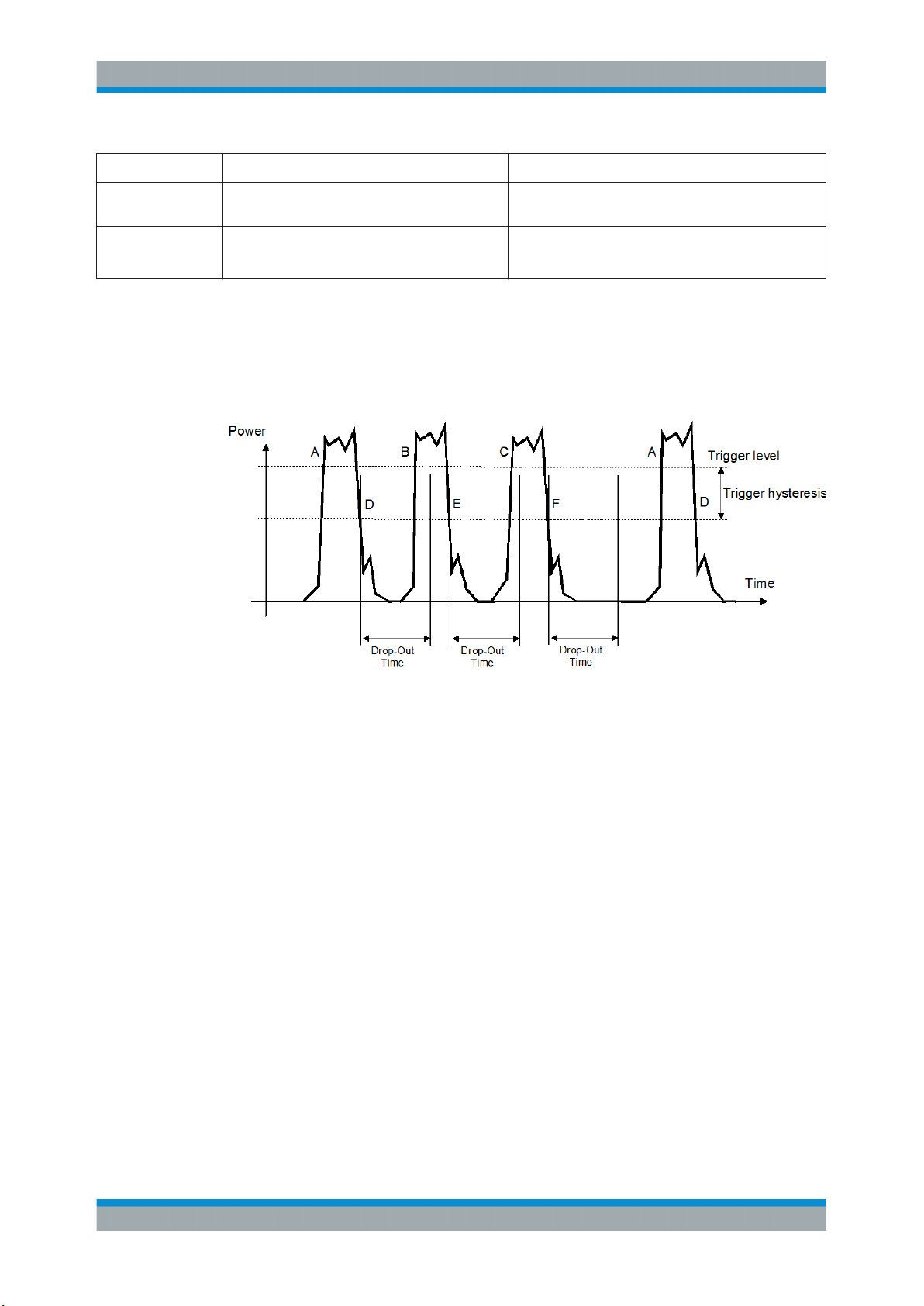
The dropout time is useful when dealing with signals with several active slots, for
example GSM signals, see Figure 7-1. When measuring in sync with the signal, a trigger event is to be produced at A, but not at B or C.
Figure 7-1: Significance of the dropout time
The RF power between the slots is below the threshold defined by the trigger level and
the trigger hysteresis. Therefore, the trigger hysteresis alone cannot prevent triggering
at B or at C. Therefore, set the dropout time greater than the time elapsed between
points D and B and between E and C, but smaller than the time elapsed between F
and A. Thus, you ensure that triggering takes place at A.
Because the mechanism associated with the dropout time is reactivated whenever the
trigger threshold is crossed, you can obtain also unambiguous triggering for many
complex signals.
If you use a hold-off time instead of a dropout time, you can obtain stable triggering
conditions - regular triggering at the same point. But you cannot achieve exclusive triggering at A.
7.5.2.5 Hold-Off Time
During the hold-off time, a period after a trigger event, all trigger events are ignored.
45User Manual 1178.8371.02 ─ 04
Page 46
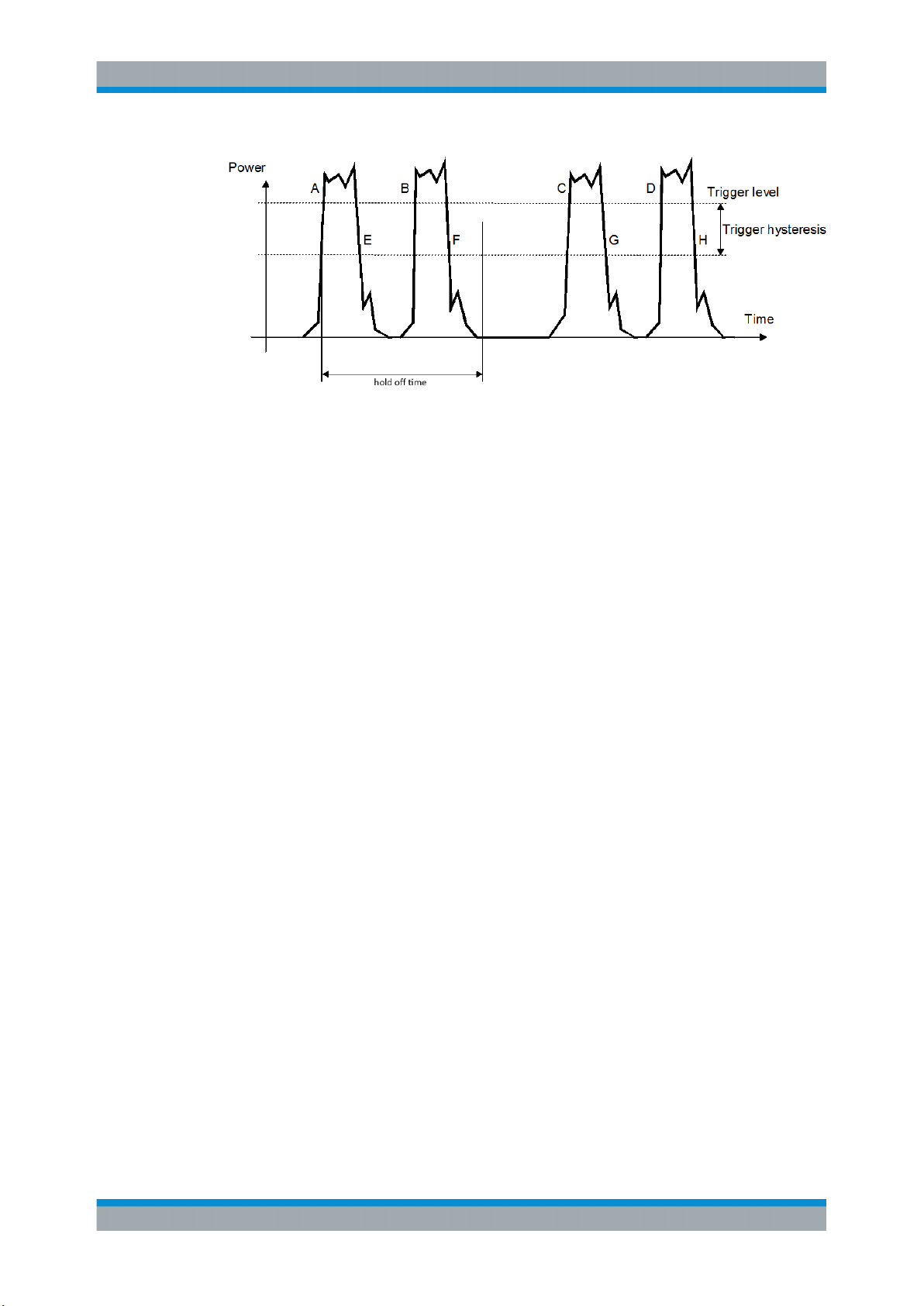
R&S®NRPxxTWG
7.5.3 Controlling the Measurement Results
Remote Control Commands
Controlling the Measurement
The R&S NRPxxTWG can cope with the wide range of measurement scenarios with
the help of the so-called "termination control". Depending on how fast your measurement results change, you can define, how the measurement results are output.
In continuous average mode, use [SENSe<Sensor>:]AVERage:TCONtrol.
Repeating termination control
Outputs a measurement result when the entire measurement has been completed.
This means that the number of measurement cycle repetitions is equal to the set average count. If the average count is large, the measurement time can be very long.
Useful if you expect slow changes in the results, and you want to avoid outputting
redundant data.
Moving termination control
Outputs intermediate values to facilitate early detection of changes in the measured
quantity. This means that for each partial measurement, a new average value is output
as a measurement result. Thus, the measurement result is a moving average of the
last partial measurements. How many of the partial measurements are averaged is
defined by the average count.
Useful if you want to detect trends in the result during the measurement.
7.5.4 Interplay of the Controlling Mechanisms
In the following examples, continuous measurement scenarios are used. But these
scenarios apply also to single measurements. The only difference is that a single measurement is not repeated.
46User Manual 1178.8371.02 ─ 04
Page 47
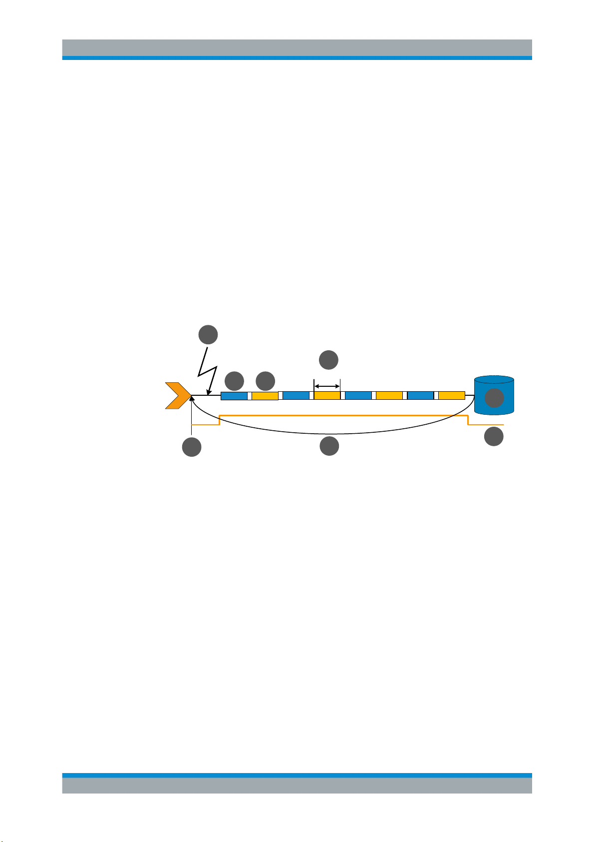
R&S®NRPxxTWG
7.5.4.1 Continuous Average Mode
Remote Control Commands
Controlling the Measurement
General settings for these examples:
●
INITiate:CONTinuous ON
●
[SENSe<Sensor>:]AVERage:COUNt 4
●
[SENSe<Sensor>:]AVERage:COUNt:AUTO OFF
Example: Repeating termination control
Further settings for this example:
●
[SENSe<Sensor>:]AVERage:TCONtrol REPeat
The measurement is started by the trigger event. Due to the chopper phases, one
measurement lasts twice the defined aperture time. As defined by the average count,
after 4 measurements, the result is averaged and available. During the whole measurement cycle, the trigger synchronization is high (TRIGger:SYNC:STATe ON).
2
5
t
3
4
1
1
= Start of the measurement cycle
2 = Trigger event
3 = Noninverted chopper phase
4 = Inverted chopper phase
5 = Duration of one aperture time (1 x tAP) ≙ length of one chopper phase
6 = Measurement result
7 = Trigger synchronization
8 = Return to the start of the measurement cycle
AP
8
6
7
47User Manual 1178.8371.02 ─ 04
Page 48
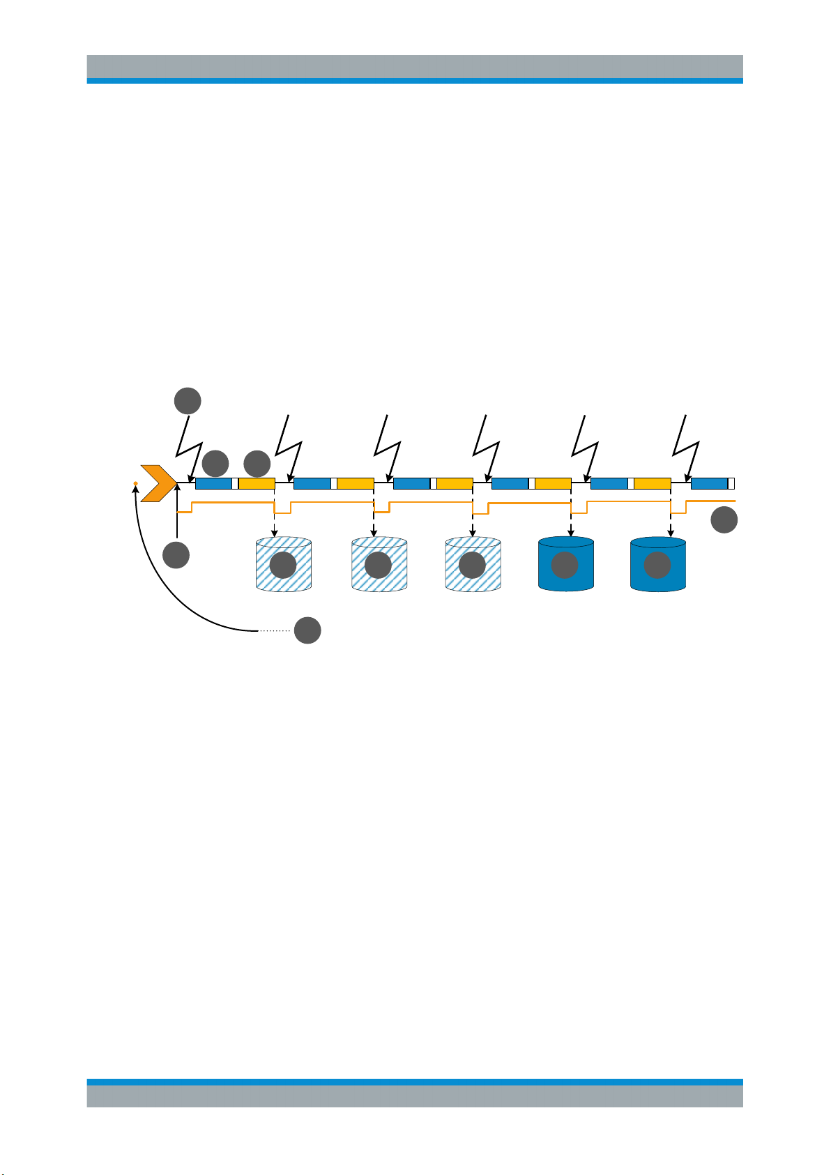
R&S®NRPxxTWG
2
Remote Control Commands
Controlling the Measurement
Example: Moving termination control
Further settings for this example:
●
[SENSe<Sensor>:]AVERage:TCONtrol MOVing
●
TRIGger:COUNt 16
Every measurement is started by a trigger event. Due to the chopper phases, one
measurement lasts twice the defined aperture time. During each measurement, the
trigger synchronization is high (TRIGger:SYNC:STATe ON). Every measurement provides a result. During the settling phase, the amount of the result is already correct, but
the noise is higher. After 4 measurements, when the average count is reached, settled
data are available.
When the trigger count is reached (TRIGger:COUNt on page 50), the power sensor
returns to the idle state.
4
3
1
6
6 6
8
1
= Start of the measurement cycle
2 = Trigger event
3 = Noninverted chopper phase
4 = Inverted chopper phase
5 = Trigger synchronization
6 = Measurement result before average count is reached
7 = Averaged measurement result after average count is reached
8 = Return to idle state after trigger count (= 16 in this example) is reached
7.5.5 Configuring the Trigger
Further information:
●
Chapter 7.5, "Controlling the Measurement", on page 42
5
7
7
Remote commands:
TRIGger:ATRigger:DELay.................................................................................................49
TRIGger:ATRigger:EXECuted?..........................................................................................49
TRIGger:ATRigger:STATe................................................................................................. 49
TRIGger:COUNt.............................................................................................................. 50
48User Manual 1178.8371.02 ─ 04
Page 49
R&S®NRPxxTWG
Remote Control Commands
Controlling the Measurement
TRIGger:DELay............................................................................................................... 50
TRIGger:DELay:AUTO..................................................................................................... 50
TRIGger:DTIMe............................................................................................................... 50
TRIGger:EXTernal<2...2>:IMPedance................................................................................ 51
TRIGger:HOLDoff............................................................................................................ 51
TRIGger:HYSTeresis........................................................................................................51
TRIGger:IMMediate..........................................................................................................52
TRIGger:LEVel................................................................................................................ 52
TRIGger:LEVel:UNIT........................................................................................................52
TRIGger:MASTer:PORT....................................................................................................52
TRIGger:MASTer:STATe................................................................................................... 53
TRIGger:SLOPe.............................................................................................................. 53
TRIGger:SOURce............................................................................................................ 53
TRIGger:SYNC:PORT......................................................................................................54
TRIGger:SYNC:STATe......................................................................................................54
TRIGger:ATRigger:DELay <delay>
Effective only if TRIGger:ATRigger:STATe is set to ON.
Sets the delay between the artificial trigger event and the beginning of the actual measurement
Parameters:
<delay> Range: 0.1 to 5.0
*RST: 2.0
Default unit: Seconds
TRIGger:ATRigger:EXECuted?
Queries the number of measurements that were triggered automatically since
TRIGger:ATRigger:STATe was set to ON.
In normal scalar measurements, this number can only be 0 or 1. If a buffered measurement was executed, this number indicates how many results in the returned array of
measurement data were executed without a real trigger event.
Usage:
Query only
TRIGger:ATRigger:STATe <state>
Controls the automatic trigger function. If enabled, an artificial trigger is generated if the
delay time has elapsed after the measurement start and no trigger event has occurred.
The delay time is set using TRIGger:ATRigger:DELay.
Parameters:
<state> *RST: OFF
49User Manual 1178.8371.02 ─ 04
Page 50
R&S®NRPxxTWG
Remote Control Commands
Controlling the Measurement
TRIGger:COUNt <count>
Sets the number of measurement cycles to be performed when the measurement is
started using INITiate[:IMMediate].
This number equals the number of results that can be obtained from the sensor after a
single measurement. As long as the defined number of measurements is not executed,
the sensor automatically initiates another measurement internally when the current
result is available.
This command is particularly useful in conjunction with buffered measurements. For
example, to fill a buffer with a predefined size with measurements that have been triggered externally or by *TRG without having to start the measurement multiple times.
Parameters:
<count> Range: 1 to 8192
*RST: 1
Example: See Chapter 8.2, "Performing a Buffered Continuous Average
Measurement", on page 97.
TRIGger:DELay <delay>
Sets the delay between the trigger event and the beginning of the actual measurement
(integration).
Parameters:
<delay> Range: -5.0 to 10.0
*RST: 0.0
Default unit: s
TRIGger:DELay:AUTO <state>
If TRIGger:DELay:AUTO ON is set, no measurement is started until the power sensor
has settled. For this purpose, the delay value is automatically determined.
If a longer period is set using TRIGger:DELay, the automatically determined delay is
ignored.
Parameters:
<state> *RST: OFF
TRIGger:DTIMe <dropout_time>
Sets the dropout time for the internal trigger source. During this time, the signal power
must exceed (negative trigger slope) or undercut (positive trigger slope) the level
defined by the trigger level and trigger hysteresis. At least, this time must elapse before
triggering can occur again.
See Chapter 7.5.2.4, "Dropout Time", on page 45.
50User Manual 1178.8371.02 ─ 04
Page 51
R&S®NRPxxTWG
Remote Control Commands
Controlling the Measurement
Parameters:
<dropout_time> Range: 0.00 to 10.00
*RST: 0.00
Default unit: s
TRIGger:EXTernal<2...2>:IMPedance <impedance>
Effective only if TRIGger:SOURce EXTernal2 is set.
Sets termination resistance of the second external trigger input. Choose the setting
that fits the impedance of the trigger source to minimize reflections on the trigger signals.
Suffix:
<2...2>
Parameters:
<impedance> HIGH | LOW
TRIGger:HOLDoff <holdoff>
Sets the hold-off time, seeChapter 7.5.2.5, "Hold-Off Time", on page 45 .
Parameters:
<holdoff> Range: 0.00 to 10.00
TRIGger:HYSTeresis <hysteresis>
.
2
HIGH
~10 kΩ
LOW
50 kΩ
*RST: HIGH
*RST: 0.00
Default unit: Seconds
Sets the hysteresis. A trigger event occurs, if the trigger level:
●
Falls below the set value on a rising slope.
●
Rises above the set value on a falling slope
Thus, you can use this setting to eliminate the effects of noise in the signal for the edge
detector of the trigger system.
Parameters:
<hysteresis> Range: 0.00 to 10.00
*RST: 0.00
Default unit: DB
51User Manual 1178.8371.02 ─ 04
Page 52
R&S®NRPxxTWG
Remote Control Commands
Controlling the Measurement
TRIGger:IMMediate
Causes a generic trigger event. The power sensor leaves the waiting for trigger state
immediately, irrespective of the trigger source and the trigger delay, and starts the
measurement.
This command is the only way to start a measurement if the trigger source is set to
hold (TRIGger:SOURce HOLD). Only one measurement cycle is executed, irrespective
of the averaging factor.
Usage: Event
TRIGger:LEVel <level>
Effective only if TRIGger:SOURceINTernal.
Sets the trigger threshold for internal triggering derived from the test signal.
If you enter a value without unit, the unit is defined by TRIGger:LEVel:UNIT.
If an S-parameter device is active and/or if a mounted component with a global offset
in front of the sensor is considered, the currently effective trigger threshold and a trigger threshold to be input are referenced to the appropriately shifted sensor data. If the
S-parameter device and/or the offset correction are disabled, the trigger threshold and
its input limits are adjusted as necessary.
Parameters:
<level> Range: 300e-9 to 100.0e-3
*RST: 3.0e-5
Default unit: Watts
TRIGger:LEVel:UNIT <unit>
Sets the unit of the trigger level if this value is entered without a unit.
See also TRIGger:LEVel on page 52.
Parameters:
<unit> DBM | W | DBUV
*RST: W
TRIGger:MASTer:PORT <master_port>
Selects the port where the sensor outputs its own trigger event in case it is trigger master. See TRIGger:MASTer:STATe for more information.
If the sensor is the trigger master, it can output its trigger event either on the
EXTernal<1> or EXTernal2.
If the sensor triggers itself, the trigger source of the sensor must be assigned to the
other external port, as shown in the examples.
52User Manual 1178.8371.02 ─ 04
Page 53
R&S®NRPxxTWG
Remote Control Commands
Controlling the Measurement
Parameters:
<master_port> EXT1 | EXTernal1 | EXT2 | EXTernal2
*RST: EXT1
Example:
Example:
TRIGger:MASTer:STATe
Enables or disables the trigger master mode of the sensor. In this state, the power sensor can output a digital trigger signal in sync with its own trigger event.
If enabled, select the output port for the trigger signal using TRIGger:MASTer:PORT.
Typically, the trigger master uses its internal trigger source. But you can also trigger the
trigger master externally, because the power sensor has got two external trigger connectors. If you trigger the trigger master externally, use EXTernal1 as external trigger
input port (trigger source) and EXTernal2 as trigger master output port or vice versa.
Parameters:
<state> *RST: OFF
TRIGger:SLOPe <slope>
TRIG:MAST:PORT EXT1
TRIG:SOUR EXT2
TRIG:MAST:STAT ON
TRIG:MAST:PORT EXT2
TRIG:SOUR EXT1
TRIG:MAST:STAT ON
<state>
Effective only if TRIGger:SOURce is set to INTernal or EXTernal.
Determines which edge of the envelope power, with internal triggering, or increasing
voltage, with external triggering, is used for triggering.
Parameters:
<slope> POSitive | NEGative
POSitive
Rising edge
NEGative
Falling edge
*RST: POSitive
TRIGger:SOURce <source>
Selects the source for the trigger event detector.
Parameters:
<source> HOLD | IMMediate | INTernal | BUS | EXTernal | EXT1 |
EXTernal1 | EXT2 | EXTernal2
See Chapter 7.5.2.3, "Trigger Sources", on page 44.
*RST: IMMediate
53User Manual 1178.8371.02 ─ 04
Page 54
R&S®NRPxxTWG
Remote Control Commands
Configuring and Retrieving Results
TRIGger:SYNC:PORT <sync_port>
Selects the external connection for the sync output of the sensor. For more information,
see TRIGger:SYNC:STATe.
Parameters:
<sync_port> EXT1 | EXTernal1 | EXT2 | EXTernal2
*RST: EXT1
TRIGger:SYNC:STATe <state>
Usually used in combination with TRIGger:MASTer:STATe ON.
If enabled, blocks the external trigger bus as long as the sensor remains in the measurement state. Thus, ensures that a new measurement is only started after all sensors have completed their measurements.
Make sure that the number of repetitions is the same for all sensors involved in the
measurement. Otherwise, the trigger bus is blocked by any sensor that has completed
its measurements before the others and has returned to the idle state.
Parameters:
<state> *RST: OFF
7.6 Configuring and Retrieving Results
● Setting the Power Unit............................................................................................ 54
● Setting the Result Format....................................................................................... 55
● Retrieving Results...................................................................................................56
7.6.1 Setting the Power Unit
The UNIT subsystem contains commands for setting up the power unit.
UNIT:POWer <unit>
Sets the output unit for the measured power values.
Parameters:
<unit> DBM | W | DBUV
*RST: W
Example:
UNIT:POW DBM
54User Manual 1178.8371.02 ─ 04
Page 55
R&S®NRPxxTWG
7.6.2 Setting the Result Format
Remote Control Commands
Configuring and Retrieving Results
The FORMat subsystem sets the format of numeric data (measured values) that is
exchanged between the remote control computer and the power sensors if high-level
measurement commands are used.
Remote commands:
FORMat:BORDer.............................................................................................................55
FORMat:SREGister..........................................................................................................55
FORMat[:DATA]...............................................................................................................55
FORMat:BORDer <border>
Selects the order of bytes in 32-bit or 64-bit binary data.
Parameters:
<border> NORMal | SWAPped
NORMal
The 1st byte is the least significant byte, the 4th/8th byte the
most significant byte.
Fulfills the Little Endian (little end comes first) convention, used
by x86/x64 CPUs, for example.
SWAPped
The 1st byte is the most significant byte, the 4th/8th byte the
least significant byte.
Fulfills the Big Endian (big end comes first) convention.
*RST: NORMal
Example:
FORM:BORD NORM
FORMat:SREGister <sregister>
Specifies which format is used for the return value of *STB?.
Parameters:
<sregister> ASCii | HEXadecimal | OCTal | BINary
*RST: ASCii
Example:
FORM:SREG ASC
FORMat[:DATA] [<data,length>, <length>]
Specifies how the R&S NRPxxTWG sends the numeric data to the controlling host/
computer.
Parameters:
<data,length> <REAL,32 | 64>
REAL
Block of binary values, 32-bit or 64-bit each; so-called "SCPI
definite length block"
55User Manual 1178.8371.02 ─ 04
Page 56
R&S®NRPxxTWG
Remote Control Commands
Configuring the Measurement Modes
32 | 64
32-bit or 64-bit
If you omit the length, the R&S NRPxxTWG sets the last used
length.
Example for REAL,32 format:
#6768000....<binary float values>....
Example for REAL,64 format:
#71536000....<binary float values>....
<data[,length]> <ASCii[,0 to 12]>
ASCii
List of comma separated, readable values.
[,0 to 12]
Defines the number of decimal places.
The reset value 0 does not restrict the number of decimal places.
Example for ASCii,4 format:
1.2938e-06, -4.7269e-11, ...
*RST: ASCii,0
7.6.3 Retrieving Results
After performing the measurement, you can query the measurement results with a
command from the FETCh subsystem.
Remote commands:
FETCh<Sensor>:ARRay[:POWer][:AVG]?.......................................................................... 56
FETCh<Sensor>[:SCALar][:POWer][:AVG]?........................................................................56
FETCh<Sensor>:ARRay[:POWer][:AVG]?
Queries the last valid measurement result of a measurement with enabled data buffer
mode.
Usage:
FETCh<Sensor>[:SCALar][:POWer][:AVG]?
Queries the last valid measurement result.
Usage:
Query only
Query only
7.7 Configuring the Measurement Modes
In the following chapter the settings needed for configuring a measurement mode are
described.
56User Manual 1178.8371.02 ─ 04
Page 57

R&S®NRPxxTWG
7.7.1 Continuous Average Measurement
Remote Control Commands
Configuring the Measurement Modes
Further information:
●
Chapter 7.8, "Configuring Basic Measurement Parameters", on page 60
●
Chapter 7.5, "Controlling the Measurement", on page 42
Contens:
● Continuous Average Measurement.........................................................................57
The Continuous Average mode measures the signal average power asynchronously
within definable time intervals (sampling windows). The aperture (width of the sampling
windows) can be defined.
Reducing noise and zero offset
The smoothing filter can reduce result fluctuations caused by modulation. But activating it increases the inherent noise of the sensor by approx. 20 %., so do not activate if
it unless required.
Configuring continuous average measurements of modulated signals
When measuring modulated signals in continuous average mode, the measurement
can show fluctuation due to the modulation. If that is the case, adapt the size of the
sampling window exactly to the modulation period to get an optimally stable display. If
the modulation period varies or is not precisely known, you can also activate the
smoothing function.
With smoothing activated, the selected sampling window has to be 5 to 9 times larger
than the modulation period so that the fluctuations caused by modulation are sufficiently reduced. The sampling values are subjected to weighting (raised-von-Hann window), which corresponds to video filtering.
If you deactivate the smoothing filter, 300 to 3000 periods are required to obtain the
same effect. The sampling values are considered equivalent and are averaged in a
sampling window, which yields an integrating behavior of the measuring instrument. To
obtain optimum suppression of variations in the result, exactly adapt the modulation
period to the size of the sampling window. Otherwise, the modulation can have a considerable influence, even if the sampling window is much larger than the modulation
period.
Calculating the measurement time
Normally, the measurement time is calculated as follows:
MT = 2 * AC * APER + (2 * AC - 1) * 100 μs
with:
MT: overall measurement time
AC: average count
APER: aperture time
57User Manual 1178.8371.02 ─ 04
Page 58
R&S®NRPxxTWG
Remote Control Commands
Configuring the Measurement Modes
100 μs is the time for switching the chopper phase.
Using [SENSe<Sensor>:][POWer:][AVG:]FAST ON, you can accelerate the measurement as follows:
●
Chopper is deactivated.
●
Average count is set to 1, no matter which average count you have set.
Thus, the overall measurement time is only defined by the aperture time, and the measurement time for a fast measurement is calculated as follows:
MT = APER
Remote commands:
[SENSe<Sensor>:][POWer:][AVG:]APERture......................................................................58
[SENSe<Sensor>:][POWer:][AVG:]BUFFer:CLEar...............................................................58
[SENSe<Sensor>:][POWer:][AVG:]BUFFer:COUNt?............................................................58
[SENSe<Sensor>:][POWer:][AVG:]BUFFer:DATA?.............................................................. 59
[SENSe<Sensor>:][POWer:][AVG:]BUFFer:SIZE.................................................................59
[SENSe<Sensor>:][POWer:][AVG:]BUFFer:STATe...............................................................59
[SENSe<Sensor>:][POWer:][AVG:]FAST............................................................................ 59
[SENSe<Sensor>:][POWer:][AVG:]SMOothing:STATe..........................................................60
[SENSe<Sensor>:][POWer:][AVG:]APERture <integration_time>
Sets the duration of the sampling window in the continuous average mode. During this
time interval, the average signal power is measured.
Parameters:
<integration_time> Range: 0.5e-3 to 0.3
*RST: 0.005
Default unit: Seconds
Example:
APER 0.005
[SENSe<Sensor>:][POWer:][AVG:]BUFFer:CLEar
Clears the contents of the result buffer in continuous average mode.
Example:
BUFF:CLE
Usage: Event
[SENSe<Sensor>:][POWer:][AVG:]BUFFer:COUNt?
Queries the number of results that are currently stored in the result buffer. Available in
continuous average mode.
Example:
BUFF:COUN?
Usage: Query only
58User Manual 1178.8371.02 ─ 04
Page 59
R&S®NRPxxTWG
Remote Control Commands
Configuring the Measurement Modes
[SENSe<Sensor>:][POWer:][AVG:]BUFFer:DATA?
Queries the results of the continuous average result buffer and returns them even if the
buffer is not full.
In contrast the FETCh? command returns a result only if the buffer is full.
Usage: Query only
[SENSe<Sensor>:][POWer:][AVG:]BUFFer:SIZE <count>
Sets the size of the result buffer in continuous average mode.
You can enable the buffer using [SENSe<Sensor>:][POWer:][AVG:]BUFFer:
STATe.
Parameters:
<count> Range: 1 to 8192
*RST: 1
Example:
[SENSe<Sensor>:][POWer:][AVG:]BUFFer:STATe <state>
Enables or disables the buffered continuous average mode. If the buffer mode is
enabled, all results generated by trigger events are collected in the sensor until the buffer is filled.
You can set the size of the buffer with [SENSe<Sensor>:][POWer:][AVG:
]BUFFer:SIZE.
Parameters:
<state> ON | OFF
Example:
[SENSe<Sensor>:][POWer:][AVG:]FAST <state>
Enables or disables a fast unchopped Continuous Average measurement. The average count is enforced to 1. Any setting for average count is silently ignored. See also
"Calculating the measurement time" on page 57.
BUFF:SIZE 1
See Chapter 8.2, "Performing a Buffered Continuous Average
Measurement", on page 97.
*RST: OFF
BUFF:STAT OFF
Parameters:
<state> *RST: OFF
Example: See Chapter 8, "Performing Measurement Tasks - Programming
Examples", on page 97.
59User Manual 1178.8371.02 ─ 04
Page 60
R&S®NRPxxTWG
Remote Control Commands
Configuring Basic Measurement Parameters
[SENSe<Sensor>:][POWer:][AVG:]SMOothing:STATe <state>
Enables or disables the smoothing filter, a steep-edge digital lowpass filter. If you cannot adjust the aperture time exactly to the modulation period, the filter reduces result
fluctuations caused by modulation.
Parameters:
<state> ON | OFF
*RST: OFF
Example:
SMO:STAT OFF
7.8 Configuring Basic Measurement Parameters
The following section describes the settings common for several measurement modes.
7.8.1 Configuring Auto Averaging
Describes the commands for automatic averaging in the continuous average measurements.
Remote commands:
[SENSe<Sensor>:]AVERage:COUNt..................................................................................60
[SENSe<Sensor>:]AVERage:COUNt:AUTO........................................................................61
[SENSe<Sensor>:]AVERage:COUNt:AUTO:MTIMe.............................................................61
[SENSe<Sensor>:]AVERage:COUNt:AUTO:NSRatio...........................................................61
[SENSe<Sensor>:]AVERage:COUNt:AUTO:RESolution.......................................................62
[SENSe<Sensor>:]AVERage:RESet...................................................................................62
[SENSe<Sensor>:]AVERage:COUNt:AUTO:TYPE.............................................................. 62
[SENSe<Sensor>:]AVERage:TCONtrol.............................................................................. 63
[SENSe<Sensor>:]AVERage[:STATe].................................................................................63
[SENSe<Sensor>:]AVERage:COUNt <count>
Sets the number of readings that are averaged for one measured value. The higher the
count, the lower the noise, and the longer it takes to obtain a measured value.
Average count is often also called averaging factor, but it designates the same thing,
i.e the number of measured values that have to be averaged for forming the measurement result.
Averaging is only effective, if [SENSe<Sensor>:]AVERage[:STATe] ON is set.
Parameters:
<count> Range: 1 to 65536
*RST: 4
Example:
AVER:COUN 1
60User Manual 1178.8371.02 ─ 04
Page 61
R&S®NRPxxTWG
Remote Control Commands
Configuring Basic Measurement Parameters
[SENSe<Sensor>:]AVERage:COUNt:AUTO <state>
Sets the mode for determining the average count.
Parameters:
<state> ON
Auto averaging: the averaging factor is continuously determined
and set depending on the level of power and other parameters.
OFF
Fixed filter: the previous, automatically determined averaging
factor is used.
ONCE
An averaging factor is determined by the filter automatic function
under the current measurement conditions and is then used in
the fixed filter mode.
*RST: ON
[SENSe<Sensor>:]AVERage:COUNt:AUTO:MTIMe
Sets an upper limit for the settling time of the auto-averaging filter if
[SENSe<Sensor>:]AVERage:COUNt:AUTO:TYPE is set to NSRatio. Thus it limits
the length of the filter.
Parameters:
<maximum_time> Range: 0.01 to 999.99
*RST: 4.00
Default unit: Seconds
[SENSe<Sensor>:]AVERage:COUNt:AUTO:NSRatio <nsr>
Determines the relative noise component in the measurement result for the measurement modes with scalar results. These measurement modes are Continuous Average,
Burst Average and Timeslot Average, provided the particular sensor supports them.
This command is only effective if the auto average calculation is enabled:
●
[SENSe<Sensor>:]AVERage:COUNt:AUTO ON
●
[SENSe<Sensor>:]AVERage:COUNt:AUTO:TYPE NSR
The noise component is defined as the magnitude of the level variation in dB caused
by the inherent noise of the sensor (two standard deviations).
The query returns the relative noise component in the measured value.
<maximum_time>
Parameters:
<nsr> Range: 100.000e-6 to 1.00
*RST: 0.01
Default unit: dB
61User Manual 1178.8371.02 ─ 04
Page 62
R&S®NRPxxTWG
Remote Control Commands
Configuring Basic Measurement Parameters
[SENSe<Sensor>:]AVERage:COUNt:AUTO:RESolution <resolution>
Defines the number of significant places for linear units and the number of decimal places for logarithmic units which should be free of noise in the measurement result.
The setting is only taken into account, if [SENSe<Sensor>:]AVERage:COUNt:AUTO
ON and [SENSe<Sensor>:]AVERage:COUNt:AUTO:TYPE RES are set.
Parameters:
<resolution> Range: 1 to 4
*RST: 3
[SENSe<Sensor>:]AVERage:RESet
Deletes all previous measurement results that the averaging filter contains and initializes the averaging filter. The filter length gradually increases from 1 to the set averaging factor. Thus, trends in the measurement result become quickly apparent. Note that
the measurement time required for the averaging filter to settle completely remains
unchanged.
Use this command if:
●
High averaging factor is set.
[SENSe<Sensor>:]AVERage:COUNt
●
Intermediate values are output as measurement results.
[SENSe<Sensor>:]AVERage:TCONtrol MOVing
●
Power has significantly decreased since the previous measurement, for example
by several powers of 10.
In this situation, previous measurement results, which are still contained in the averaging filter, strongly affect the settling of the display. As a result, the advantage of detecting trends in the measurement result while the measurement is still in progress is lost.
Example:
Usage: Event
[SENSe<Sensor>:]AVERage:COUNt:AUTO:TYPE <type>
Sets the automatic averaging filter mode.
Parameters:
<type> RESolution | NSRatio
AVER:RES
RESolution
The usual mode for the power sensors.
NSRatio
Predefines the compliance to an exactly defined noise component.
*RST: RESolution
62User Manual 1178.8371.02 ─ 04
Page 63
R&S®NRPxxTWG
Remote Control Commands
Configuring Basic Measurement Parameters
[SENSe<Sensor>:]AVERage:TCONtrol <mode>
Defines how the measurement results are output. This is called termination control.
See also Chapter 7.5, "Controlling the Measurement", on page 42.
Parameters:
<mode> MOVing | REPeat
MOVing
Outputs intermediate values to facilitate early detection of
changes in the measured quantity. In the settled state, that
means when the number of measurements specified by the
average count has been performed, a moving average is output.
REPeat
Specifies that a measurement result is not output until the entire
measurement has been completed. This means that the number
of measurement cycle repetitions is equal to the set average
count. If the average count is large, the measurement time can
be very long.
The average count is set using [SENSe<Sensor>:]AVERage:
COUNt on page 60.
*RST:
REPeat
Example:
[SENSe<Sensor>:]AVERage[:STATe] <state>
Available in continuous average mode.
Enables or disables the averaging filter.
Parameters:
<state> *RST: ON
AVER:TCON REP
7.8.2 Setting the Frequency
The frequency of the signal to be measured is not automatically determined. For achieving better accuracy, the carrier frequency of the applied signal must be set.
[SENSe<Sensor>:]FREQuency <frequency>
Transfers the carrier frequency of the RF signal to be measured. This frequency is
used for the frequency-response correction of the measurement result.
The center frequency is set for broadband signals, e.g. spread-spectrum signals, multicarrier signals.
Parameters:
<frequency> Range: 0.0 to 110.0e9
*RST: 50.0e6
Default unit: Frequency
63User Manual 1178.8371.02 ─ 04
Page 64
R&S®NRPxxTWG
Remote Control Commands
Configuring Basic Measurement Parameters
Example:
FREQ 10000
7.8.3 Configuring Corrections
It is possible to set some parameters that compensate for a change of the measured
signal due to fixed external influences.
● Duty Cycle Corrections........................................................................................... 64
● Offset Corrections................................................................................................... 64
● S-Parameter Correction.......................................................................................... 65
● S-Gamma Corrections............................................................................................ 67
● Using the S-Parameters Tool.................................................................................. 69
7.8.3.1 Duty Cycle Corrections
The duty cycle is the percentage of one period during which the signal is active, when
pulse-modulated signals are corrected. The duty cycle is only evaluated in the Continuous Average mode.
Remote commands:
[SENSe<Sensor>:]CORRection:DCYCle............................................................................ 64
[SENSe<Sensor>:]CORRection:DCYCle:STATe..................................................................64
[SENSe<Sensor>:]CORRection:DCYCle <duty_cycle>
Available in continuous average mode.
Sets the duty cycle for measuring pulse-modulated signals. The duty cycle defines the
percentage of one period during which the signal is active. If the duty cycle is enabled,
the R&S NRPxxTWG takes this percentage into account when calculating the signal
pulse power from the average power.
Parameters:
<duty_cycle> Range: 0.001 to 100.00
[SENSe<Sensor>:]CORRection:DCYCle:STATe <state>
Enables or disables the duty cycle correction for the measured value.
Parameters:
<state> *RST: OFF
7.8.3.2 Offset Corrections
The offset accounts for external losses by adding a fixed level offset in dB.
*RST: 1.00
Default unit: Percent
The attenuation of an attenuator located ahead of the sensor (or the coupling attenuation of a directional coupler) is taken into account with a positive offset, i.e. the sensor
64User Manual 1178.8371.02 ─ 04
Page 65
R&S®NRPxxTWG
Remote Control Commands
Configuring Basic Measurement Parameters
calculates the power at the input of the attenuator or the directional coupler. A negative
offset can be used to correct the influence of an amplifier connected ahead.
Using S-parameters instead of a fixed offset allows more precise measurements,
because the interaction between the sensor and the component can be taken into
account. See also Chapter 7.8.3.3, "S-Parameter Correction", on page 65.
Remote commands:
[SENSe<Sensor>:]CORRection:OFFSet............................................................................ 65
[SENSe<Sensor>:]CORRection:OFFSet:STATe.................................................................. 65
[SENSe<Sensor>:]CORRection:OFFSet <offset>
Sets a fixed offset that is added to correct the measured value.
Parameters:
<offset> Range: -200.00 to 200.00
*RST: 0
Default unit: dB
[SENSe<Sensor>:]CORRection:OFFSet:STATe <state>
Enables or disables the offset correction.
Parameters:
<state> *RST: OFF
Example:
CORR:OFFS:STAT ON
7.8.3.3 S-Parameter Correction
S-parameter correction compensates for the losses and reflections introduced by a
component – such as an attenuator, directional coupler, or matching pad – that is
attached to a power sensor. Using S-parameters instead of a fixed offset increases
measurement accuracy by accounting for the interaction between the sensor and the
component. It shifts the reference plane of the sensor from its RF connector to the
input of the device that is being applied externally. For more information on the fundamentals of the S-parameters and for application example, see also 1GP70: Using S-
Parameters with R&S®NRP-Z Power Sensors.
All R&S NRPxxTWG power sensors allow compensating for the influence of any 2-port
device between the signal source and the sensor input. As a result, the firmware can
calculate the power that the signal source actually delivers. Examples of such 2-port
devices include attenuators, matching pads, minimum-loss pads and waveguide adapters. One precondition for such compensation is that you provide a complete set of Sparameter data for the 2-port device in the frequency range required by the application.
The S-parameters of the attenuator delivered with the R&S NRPxxTWG have been
measured by Rohde & Schwarz. The results of the factory calibration, including an Sparameter table that matches the delivered attenuator, are stored in the factory calibra-
65User Manual 1178.8371.02 ─ 04
Page 66
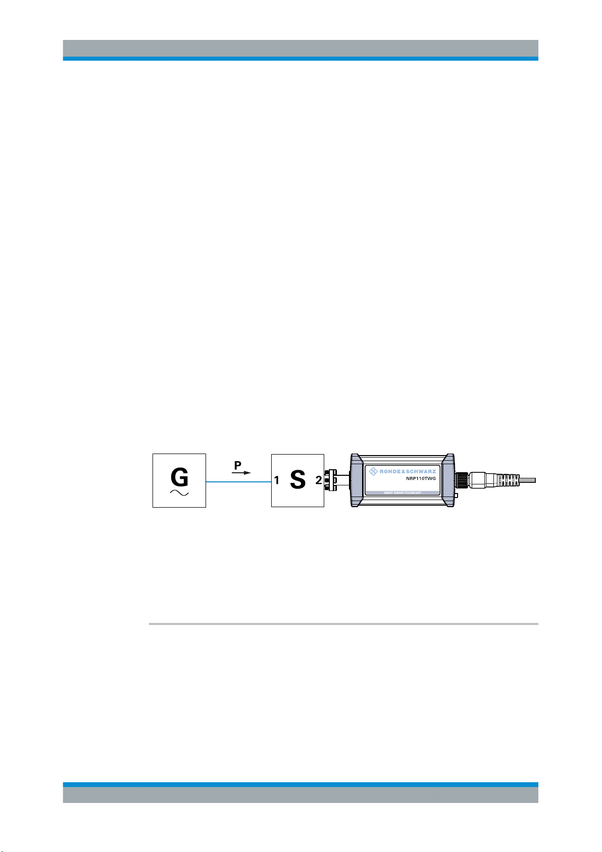
R&S®NRPxxTWG
Remote Control Commands
Configuring Basic Measurement Parameters
tion data set of the sensor. If you use this attenuator, its effect on the measurement is
compensated arithmetically.
Achieving Maximum Measurement Sensitivity
For maximum measurement sensitivity, you can choose from the following methods.
To operate the R&S NRPxxTWG without an attenuator
► Disable the S-parameter correction:
● Each time after you have put the power sensor into operation.
[SENSe<Sensor>:]CORRection:SPDevice:STATe.
● Permanently, using the S-Parameters tool.
See Chapter 7.8.3.5, "Using the S-Parameters Tool", on page 69.
To replace the delivered attenuator with any other 2-port device
1. Measure the S-parameters of the 2-port device.
2. Load the S-parameters into the power sensor.
In the user calibration data set of the power sensor, you can manage the S-parameters of several 2-port devices beside the S-parameters of the attenuator delivered
with the power sensor. The sensor can apply the sets of S-parameters individually,
depending on which S-parameter device you select as the active device.
3. Make sure that the S-parameter settings - selected S-parameter device, S-parameter correction state - always match the used hardware configuration.
Figure 7-2: Operation with 2-port device between signal source and sensor input
Configuring the S-Parameter Correction
[SENSe<Sensor>:]CORRection:SPDevice:LIST?................................................................66
[SENSe<Sensor>:]CORRection:SPDevice:SELect.............................................................. 67
[SENSe<Sensor>:]CORRection:SPDevice:STATe............................................................... 67
[SENSe<Sensor>:]CORRection:SPDevice:LIST?
Queries the list of the S-parameter data sets that have been loaded to the power sensor. The result of the query indicates the consecutive number and mnemonic of each
data set.
Usage:
Query only
66User Manual 1178.8371.02 ─ 04
Page 67
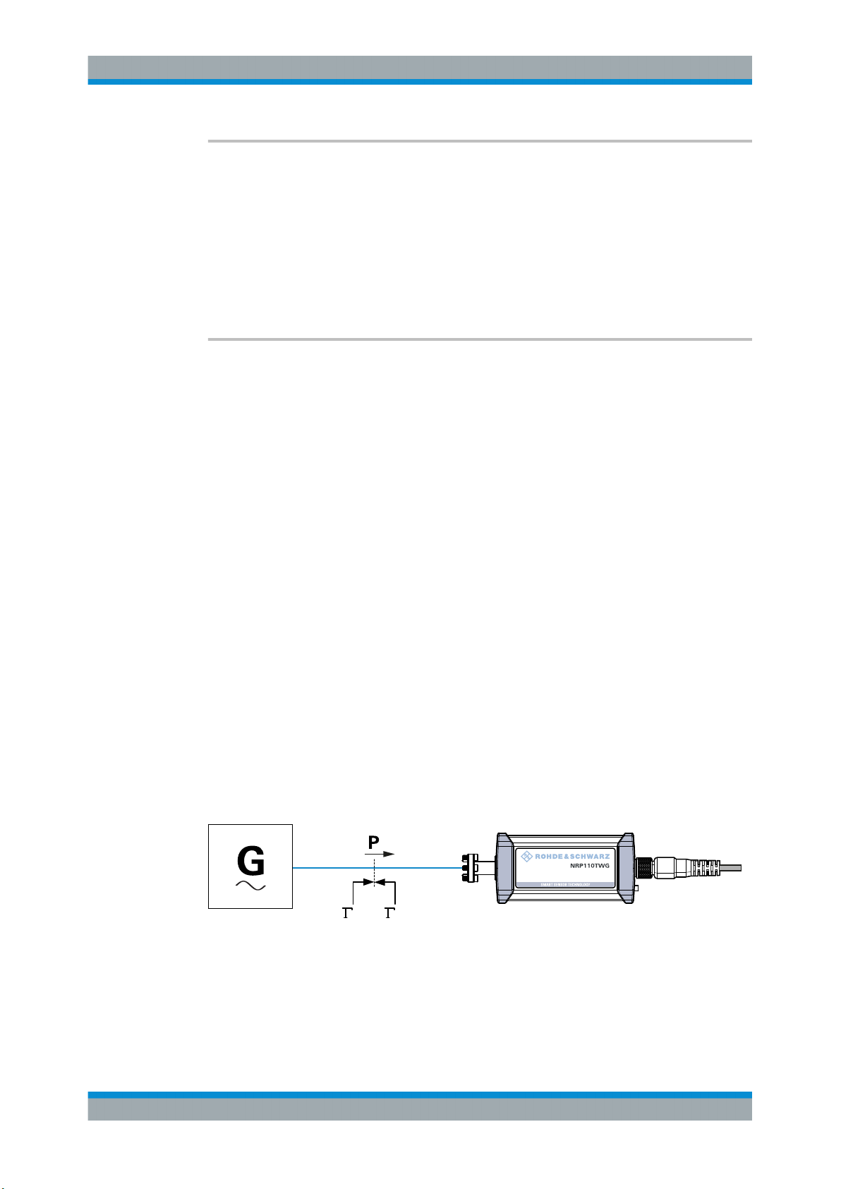
R&S®NRPxxTWG
Remote Control Commands
Configuring Basic Measurement Parameters
[SENSe<Sensor>:]CORRection:SPDevice:SELect <num>
Selects a loaded data set for S-parameter correction.
See also Chapter 7.8.3.3, "S-Parameter Correction", on page 65.
Parameters:
<num> Range: 1 to 1999
*RST: 1
Manual operation: See "S-Parameter Device Locked" on page 72
[SENSe<Sensor>:]CORRection:SPDevice:STATe <state>
Activates or deactivates the S-parameter correction. If activated, uses the S-parameter
data set selected by [SENSe<Sensor>:]CORRection:SPDevice:SELect.
See also Chapter 7.8.3.3, "S-Parameter Correction", on page 65.
Parameters:
<state> *RST: OFF
Example:
Manual operation: See "S-Parameter Correction State Locked" on page 72
7.8.3.4 S-Gamma Corrections
Using the complex reflection coefficient, you can determine the power P delivered by
the signal source with considerably greater accuracy.
The coefficient of the signal source Γ
●
[SENSe<Sensor>:]SGAMma:MAGNitude
●
[SENSe<Sensor>:]SGAMma:PHASe
The complex reflection coefficient Γ
correction, is prestored in the calibration data memory for many frequencies.
CORR:SPD:SEL 1
Selects a S-parameter correction data set.
CORR:SPD:STAT ON
Activates the S-parameter correction.
is defined by its magnitude and phase:
source
of the sensor, which is also required for the
sensor
Source
Sensor
Figure 7-3: Correction of interactions between the power sensor and the signal source
67User Manual 1178.8371.02 ─ 04
Page 68
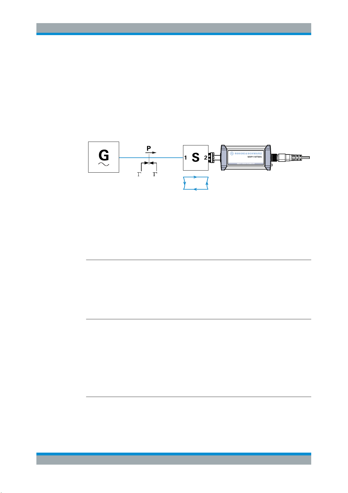
R&S®NRPxxTWG
Remote Control Commands
Configuring Basic Measurement Parameters
If the gamma correction is performed in combination with an S-parameter correction
([SENSe<Sensor>:]CORRection:SPDevice:STATe ON), the following is taken into
account:
●
Interaction of the signal source with the S-parameter device
●
Input of the power sensor, depending on the transmission, expressed by the term
s12s
21
If the S-parameter correction is enabled, the interaction between the complex reflection
coefficient Γ
of the power sensor and the reflection of port 2, expressed by s22, is
sensor
always taken into account, regardless whether gamma correction is performed or not.
Source
Sensor
S
21
S
11
S
22
S
12
Figure 7-4: Correction of interactions between the power sensor, the signal source, and the S-param-
eter device
Remote commands:
[SENSe<Sensor>:]SGAMma:CORRection:STATe................................................................68
[SENSe<Sensor>:]SGAMma:MAGNitude........................................................................... 68
[SENSe<Sensor>:]SGAMma:PHASe................................................................................. 68
[SENSe<Sensor>:]SGAMma:CORRection:STATe <state>
Enables or disables the use of the complex reflection coefficient to correct the interactions of power sensor and signal source.
Parameters:
<state> *RST: OFF
[SENSe<Sensor>:]SGAMma:MAGNitude <magnitude>
Sets the magnitude of the complex reflection coefficient of the source, Γ
source
.
Parameters:
<magnitude> 0.0 ≙ ideal matched source
1.0 ≙ total reflection
Range: 0.0 to 1.0
*RST: 0.0
[SENSe<Sensor>:]SGAMma:PHASe <phase>
Sets the phase angle of the complex reflection coefficient of the source, Γ
source
.
68User Manual 1178.8371.02 ─ 04
Page 69
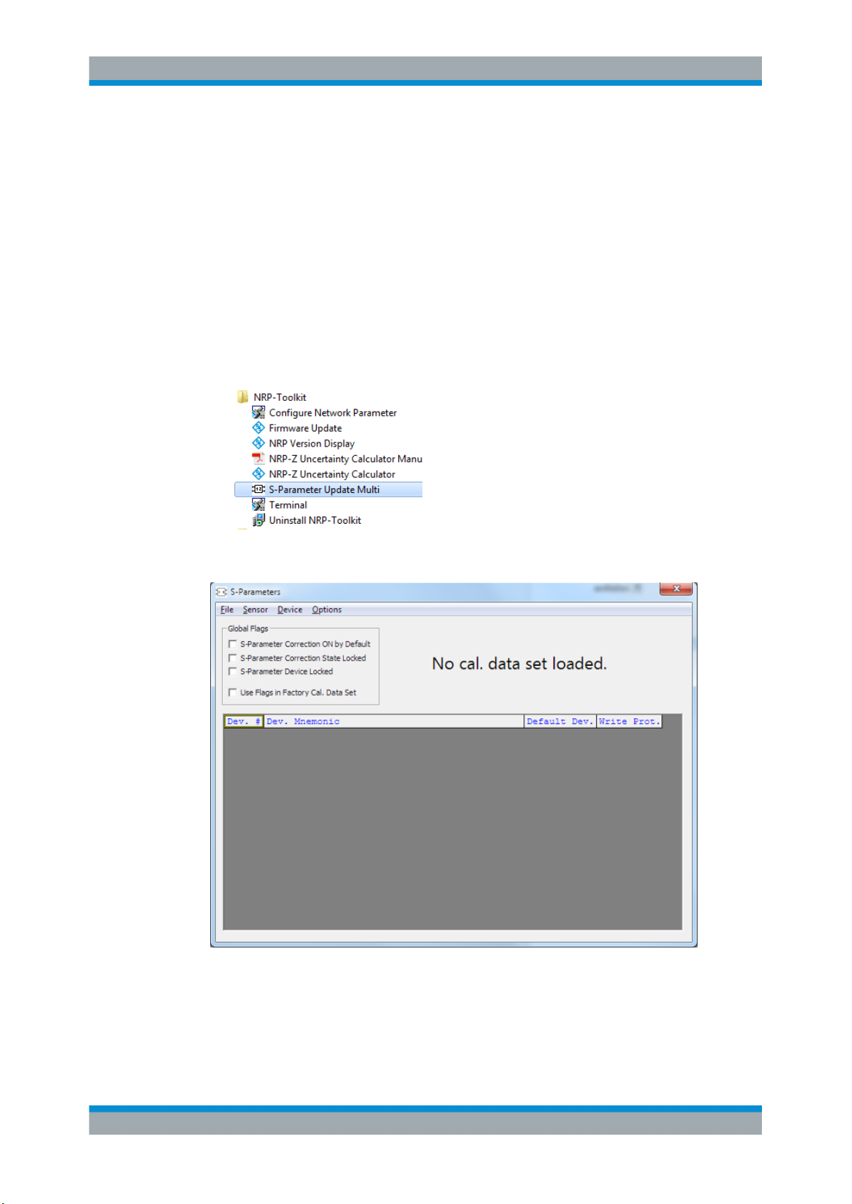
R&S®NRPxxTWG
7.8.3.5 Using the S-Parameters Tool
Remote Control Commands
Configuring Basic Measurement Parameters
Parameters:
<phase> Range: -360.0 to 360.0
*RST: 0.0
The S-Parameters tool helps loading an S-parameter table into the power sensor. The
S-Parameters tool is part of the R&S NRP Toolkit, see Chapter 5.1, "R&S NRP Toolkit",
on page 19.
To start the S-Parameters tool
► In the Windows start menu, select "NRP Toolkit" > "S-Parameter Update Multi".
User Interface of the S-Parameters Tool
Figure 7-5: S-Parameters dialog
Menu bar.......................................................................................................................70
└ File.................................................................................................................. 70
└ Sensor.............................................................................................................70
69User Manual 1178.8371.02 ─ 04
Page 70
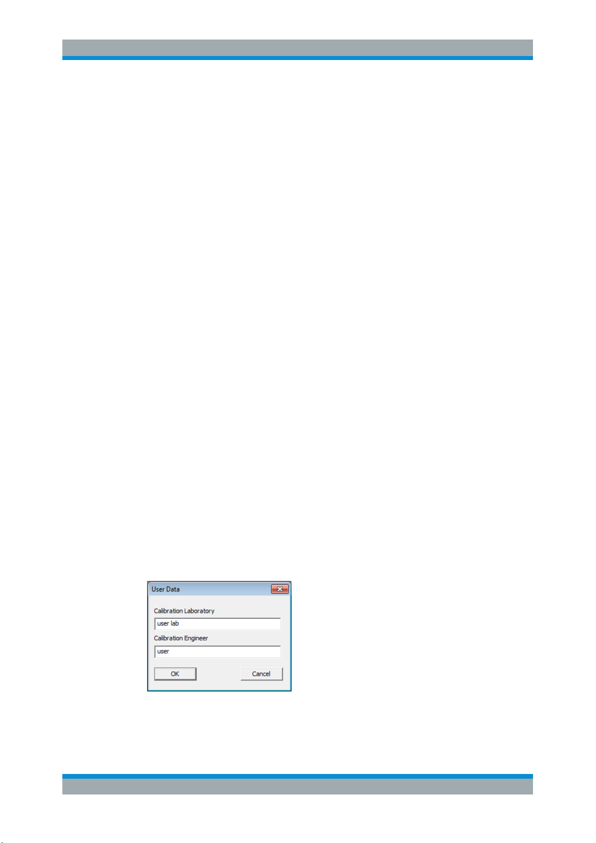
R&S®NRPxxTWG
Remote Control Commands
Configuring Basic Measurement Parameters
└ Device.............................................................................................................70
└ Options............................................................................................................70
└ User Data..............................................................................................70
└ Remote................................................................................................. 71
└ Show Cal. Data.....................................................................................71
Global Flags..................................................................................................................71
└ S-Parameter Correction ON by Default.......................................................... 71
└ S-Parameter Correction State Locked............................................................72
└ S-Parameter Device Locked...........................................................................72
└ Use Flags in Factory Cal. Data Set.................................................................72
Device table.................................................................................................................. 72
Menu bar
Contains the following submenus.
File ← Menu bar
Provides options for loading and saving calibration data files, see:
●
"To change the S-parameter data" on page 74
●
"To load an uncertainty parameter file" on page 75
Sensor ← Menu bar
Provides options for loading and saving calibration data directly from or to the sensor,
see:
●
"To load a calibration data set from a power sensor" on page 73
●
"To save the calibration data to the sensor" on page 76
Device ← Menu bar
Provides functions for editing the table of S-parameter devices.
Options ← Menu bar
Provides functions for editing user data, changing remote control timeouts, and displaying calibration data as plain text.
User Data ← Options ← Menu bar
Opens the "User Data" dialog.
Here, you can enter the name of the calibration laboratory and the calibration engineer
that is stored in the calibration data set if changes are made.
70User Manual 1178.8371.02 ─ 04
Page 71
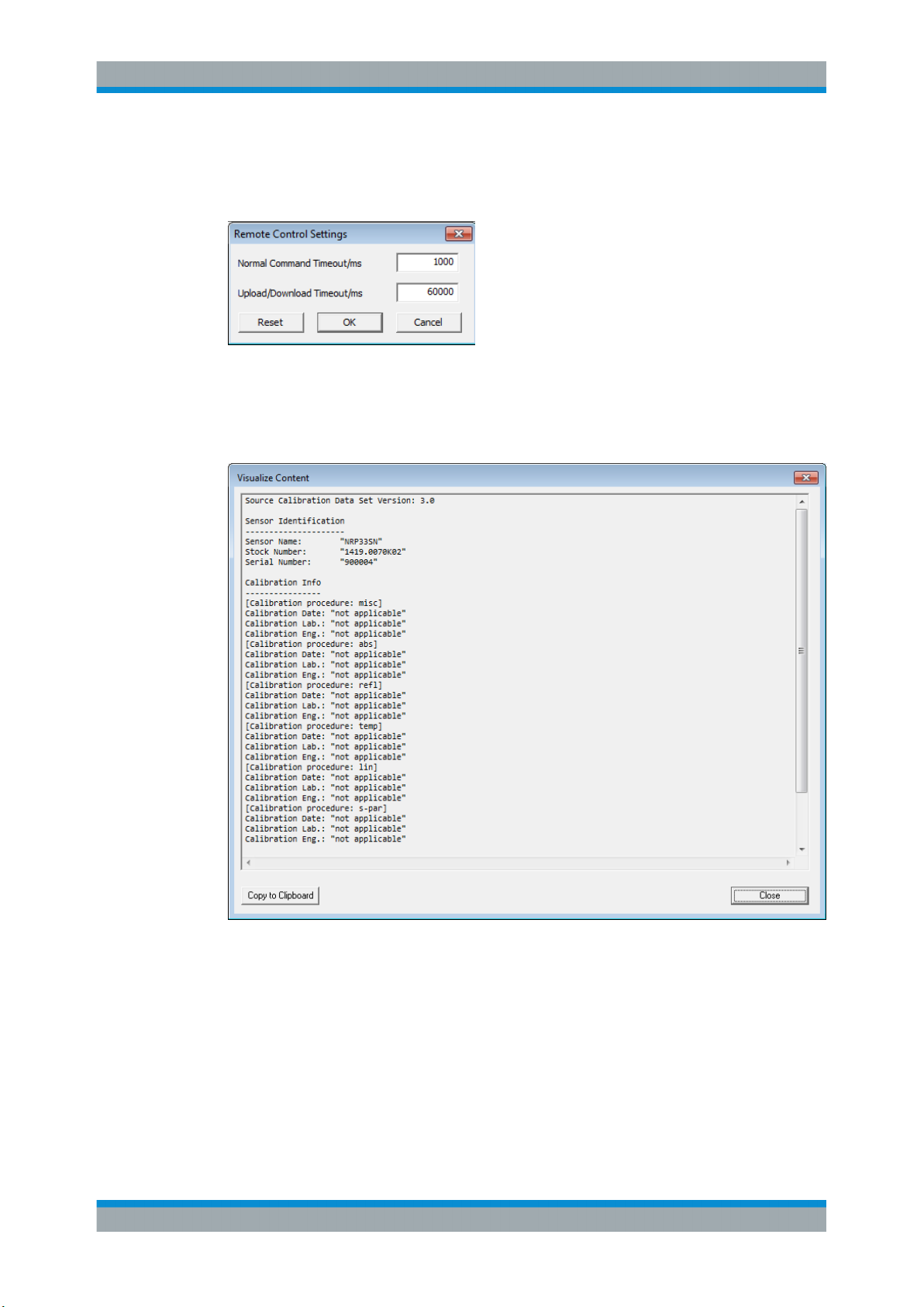
R&S®NRPxxTWG
Remote Control Commands
Configuring Basic Measurement Parameters
Remote ← Options ← Menu bar
Opens the "Remote Control Settings" dialog. It is normally not necessary to change
timeouts.
Show Cal. Data ← Options ← Menu bar
Displays the content of the calibration data set that has been loaded either from a file
of directly from a sensor as a plain text.
You can copy the text output to the clipboard by clicking "Copy to Clipboard."
Figure 7-6: Example
Global Flags
Groups the settings for the power sensor behavior regarding S-parameter corrections.
S-Parameter Correction ON by Default ← Global Flags
If this option is enabled, the S-parameter correction is activated automatically when the
sensor is started.
71User Manual 1178.8371.02 ─ 04
Page 72
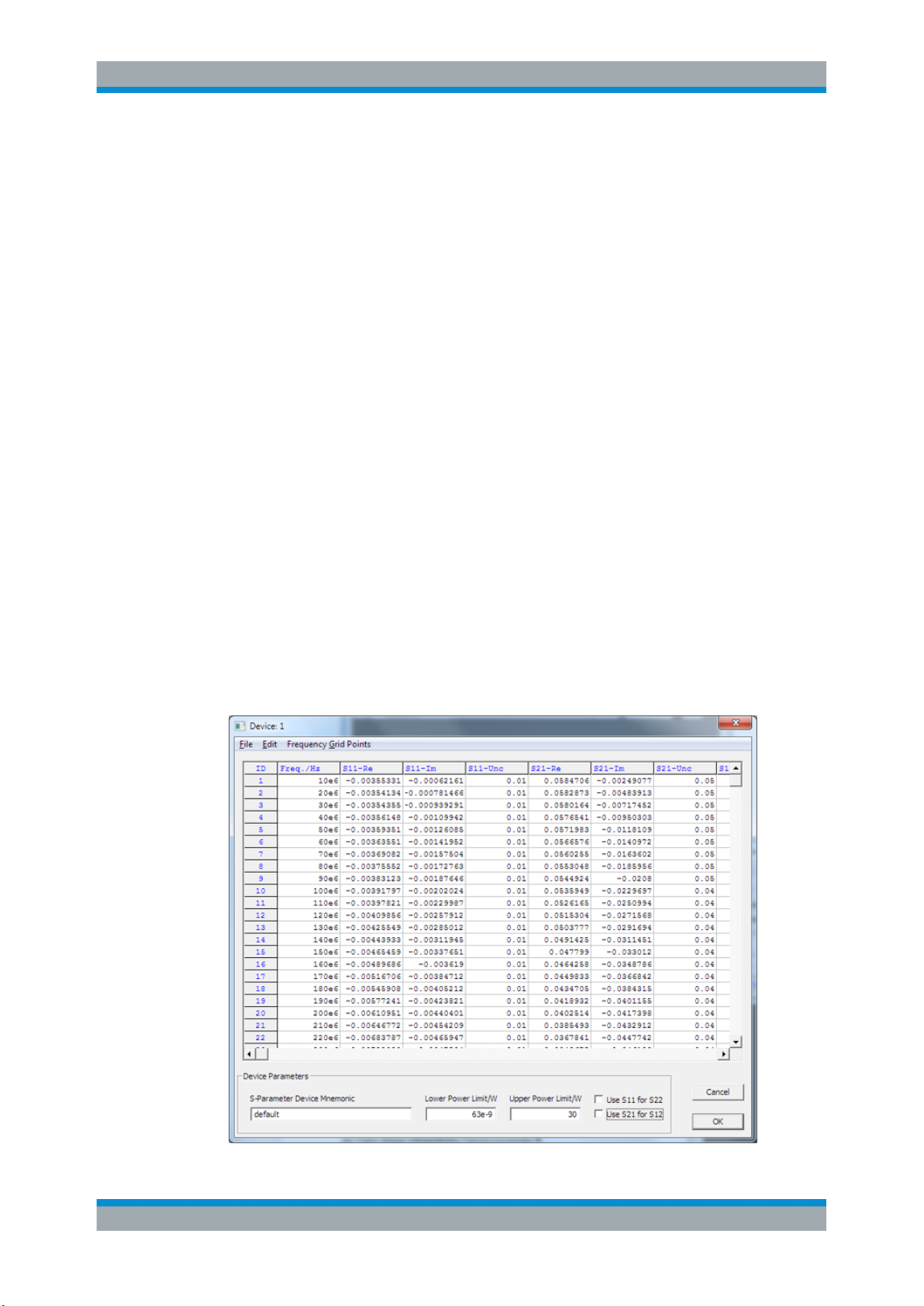
R&S®NRPxxTWG
Remote Control Commands
Configuring Basic Measurement Parameters
S-Parameter Correction State Locked ← Global Flags
If enabled, the state that is selected with "S-Parameter Correction ON by Default" is
locked and cannot be changed using:
●
[SENSe<Sensor>:]CORRection:SPDevice:STATe
●
R&S NRP2 base unit
S-Parameter Device Locked ← Global Flags
If enabled, the S-parameter device that is selected as the default device in the table of
S-parameter devices is locked and cannot be changed using:
●
[SENSe<Sensor>:]CORRection:SPDevice:SELect
●
R&S NRP2 base unit
The default S-parameter device is the S-parameter device that you have selected
when the power sensor is started.
Use Flags in Factory Cal. Data Set ← Global Flags
Available if the power sensor supports two different calibration data sets:
●
Factory calibration data set containing all factory calibration data.
●
User calibration data set that contains the S-parameter devices you have loaded.
Note: After you have added S-parameter devices and configured the global flags, disable this option. Otherwise, it is not possible to enable S-parameter correction because
the flags in the factory calibration data set prevent it.
Device table
Shows a list of all S-parameter devices that are available in the calibration data set.
If you double-click an entry, a dialog for the device is opened that allows to import,
export, and edit S-parameter data. See "To change the S-parameter data"
on page 74.
72User Manual 1178.8371.02 ─ 04
Page 73
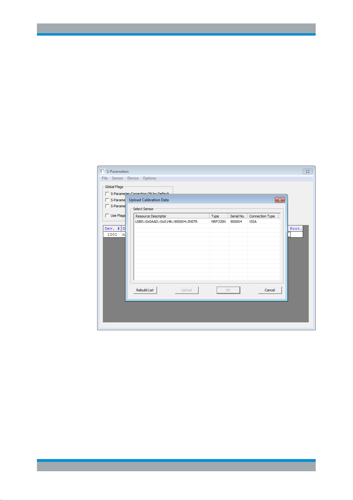
R&S®NRPxxTWG
Remote Control Commands
Configuring Basic Measurement Parameters
Performing Configuration Tasks
In this chapter, different configuration tasks performed with the power sensor and the
"S-Parameter Update Multi" tool are described.
To load a calibration data set from a power sensor
Prerequsites: The power sensor is connected to the computer and a connection is
established.
1. Open the "S-Parameter Update Multi" program.
2. Select "Sensor" > "Load Calibration Data".
The "Upload Calibration Data" dialog opens. It shows a list of the available sen-
sors.
3. If you cannot find your power sensor in the list, for example because of reconnecting the power sensor, you can reload the list by clicking "Rebuild List".
4. Click "Upload" to load calibration data from the power sensor.
After the upload is finished, the "OK" button is enabled.
5. Click "OK" to apply the changes.
If you want to discard the changes, exit the dialog by clicking "Cancel".
After a successful upload, the name and serial number is shown in the name of the
main dialog.
73User Manual 1178.8371.02 ─ 04
Page 74
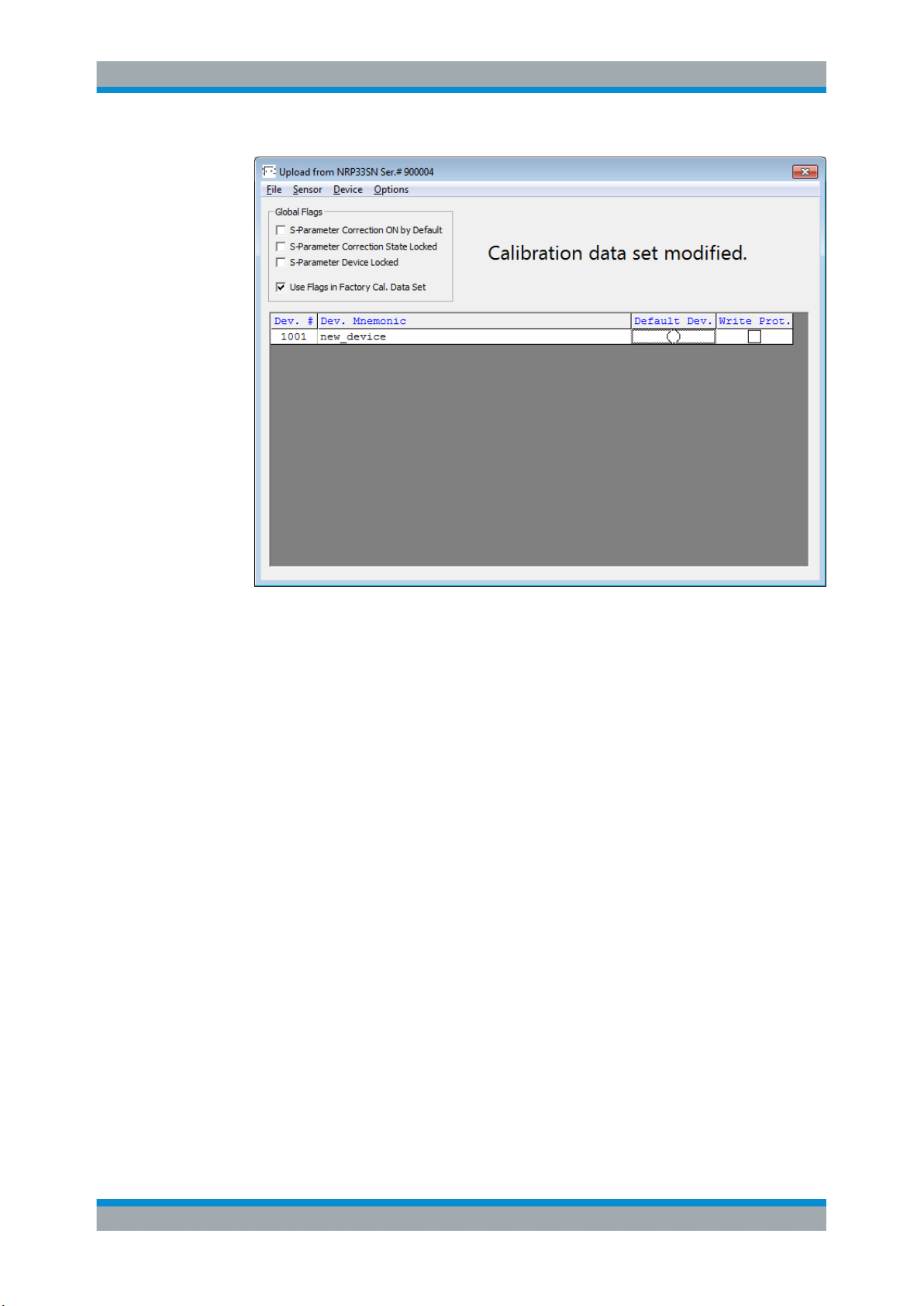
R&S®NRPxxTWG
Remote Control Commands
Configuring Basic Measurement Parameters
6. Create a backup of the calibration data set before making any changes.
Select "File" > "Save Calibration Data".
A dialog opens where you can select the location to save the calibration data.
To change the S-parameter data
1. In the device table, double-click an entry. See also "Device table" on page 72.
2. Select "File" > "Import S2P".
3. Select the *.S2P file you want to import, and confirm with "Open".
The data from the selected file is loaded in the device table.
All uncertainties are set to zero.
74User Manual 1178.8371.02 ─ 04
Page 75
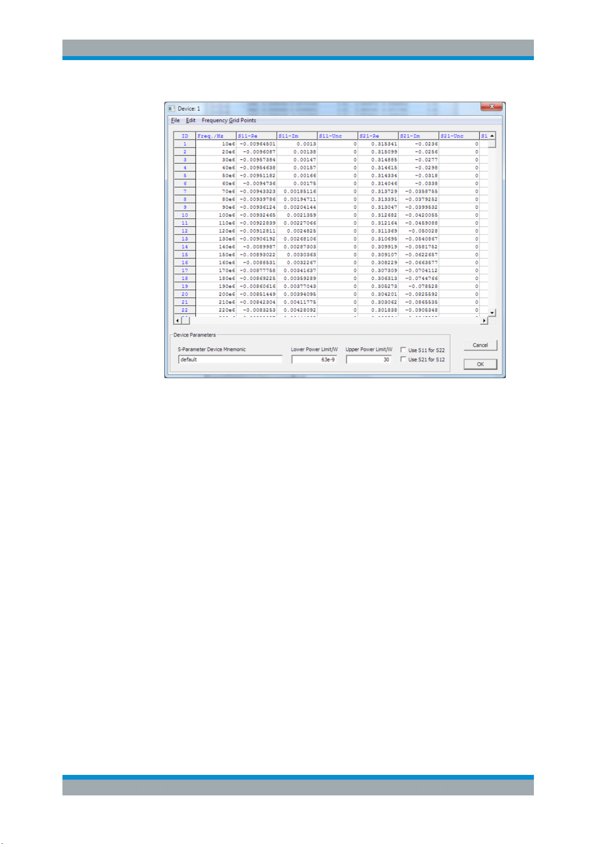
R&S®NRPxxTWG
Remote Control Commands
Configuring Basic Measurement Parameters
4. If needed, load uncertainty data. See "To load an uncertainty parameter file"
on page 75.
5. Check the entries in the "S-Parameter Device Mnemonic", "Lower Power Limit/W"
and "Upper Power Limit/W" fields and change them, if necessary.
For example, the lower and upper power limits are deduced from the power limits
of the sensor itself and the minimum attenuation of the S-parameter device. If the
"Upper Power Limit/W" entry is higher than the power dissipation rating of the
attenuator, reduce it accordingly.
6. Click "OK" to apply the changes.
If you want to discard the change, click "Cancel".
To load an uncertainty parameter file
1. In the device table, double-click an entry. See also "Device table" on page 72.
2. Select "File" > "Import uncertainties".
3. Select the file you want to import, and confirm with "Open".
The data from the selected file is loaded in the device table.
75User Manual 1178.8371.02 ─ 04
Page 76
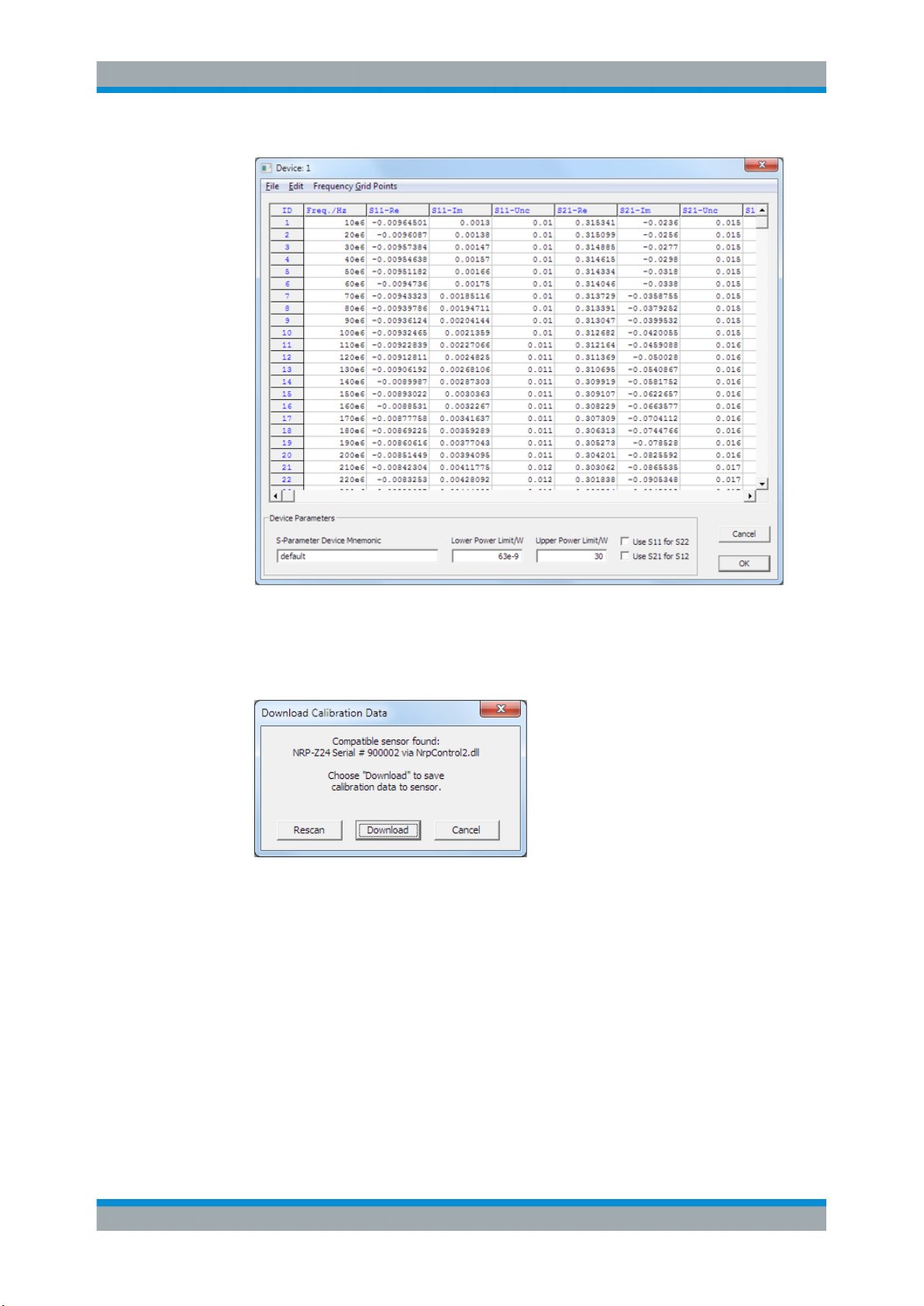
R&S®NRPxxTWG
Remote Control Commands
Configuring Basic Measurement Parameters
To save the calibration data to the sensor
1. Select "Sensor" > "Save Calibration Data".
The "Download Calibration Data" dialog opens.
2. Confirm that the correct power sensor is selected by clicking "Download".
After a successful transfer of the data to the power sensor, a confirmation message
is displayed.
The sensor can be used with the new S-parameter data.
S2P Measurement Data Files
S2P files are human-readable text files that contain header information and the complex S-parameters of the device under test in columns. This chapter briefly describes
the format of the S2P file.
An S2P measurement data file has the following structure (square brackets indicate
that the enclosed content is optional):
76User Manual 1178.8371.02 ─ 04
Page 77

R&S®NRPxxTWG
Remote Control Commands
Configuring Basic Measurement Parameters
●
Option line
The option line has the format #[<frequency unit>][<parameter>][<format>][<R n>],
where:
– #
Identifies the option line.
– <frequency unit>
Possible values are Hz, kHz, MHz or GHz. If a frequency unit is not specified,
GHz is implicitly assumed.
– <parameter> For S-parameter files. If a parameter is not specified, S is implic-
itly assumed.
– <format>
Possible values are MA (linear magnitude and phase in degree), DB (magnitude in dB, phase in degree) or RI (real and imaginary part). If a format is not
specified, MA is implicitly assumed.
– <R n>
R is optional and followed by the reference impedance in Ω. If no entry is
made, R50 is implicitly assumed.
The option line therefore reads:
# [HZ | KHZ | MHZ | GHZ] [S] [MA | DB | RI] [R 50].
●
Measurement frequencies
The measurement frequencies are listed in ascending order and are specified as
follows:
s11( fi) s21( fi) s12 ( fi) s22 ( fi)
f
i
where fi is the i-th frequency and sjk( fi) is the display format as specified in the
option line:
– | sjk( fi)| arg sjk( fi)
Display format for linear magnitude and phase in degree (MA)
– 20.lg| sjk( fi)| arg sjk( fi)
Display format for magnitude in dB and phase in degree (DB)
– Re| sjk( fi)| Im| sjk( fi)|
Display format for real and imaginary part (RI)
●
Comments
Any line starting with an exclamation mark (!) is interpreted as a comment line.
Uncertainty Data Files
An uncertainty data file has the following structure (square brackets indicate that the
enclosed content is optional):
●
Option line
The option line has the format #[<frequency unit>]<parameter>[<format>][<R n>],
where:
– #
Identifies the option line.
– <frequency unit>
Possible values are Hz, kHz, MHz or GHz. If a frequency unit is not specified,
GHz is implicitly assumed.
77User Manual 1178.8371.02 ─ 04
Page 78
R&S®NRPxxTWG
Remote Control Commands
Calibrating/Zeroing the Power Sensor
– <parameter>
U must be specified for uncertainty data files. If a parameter is not specified, S
is implicitly assumed and as a result an error message is triggered.
– <format>
This value is ignored in uncertainty measurement files. The entry is therefore
irrelevant.
– <R n>
R is optional and followed by the reference impedance in Ω. If no entry is
made, R50 is implicitly assumed.
The option line therefore reads:
# [HZ | KHZ | MHZ | GHZ] U [MA | DB | RI] [R 50].
●
Measurement frequencies
The measurement frequencies are listed in ascending order and are specified as
follows:
unc[s11( fi)] unc[s21( fi)] unc[s12 ( fi)] unc[s22 ( fi)]
f
i
where fi is the i-th frequency and unc[ sjk( fi)] is the uncertainty of the S-parameters
that is forwarded as follows:
– As extended absolute uncertainty ( k = 2 ) for the magnitude of reflection
parameters s11 and s
22
– As extended uncertainties ( k = 2 ) in dB for the magnitude of transmission
●
Comments
parameters s21 and s
12
Any line starting with an exclamation mark (!) is interpreted as a comment line.
7.9 Calibrating/Zeroing the Power Sensor
Zeroing removes offset voltages from the analog circuitry of the sensors, so that there
are only low powers displayed when there is no power applied. The zeroing process
may take more than 8 seconds to complete.
Zeroing is recommended if:
●
The temperature has varied by more than 5 K.
●
The sensor has been replaced.
●
No zeroing was performed in the last 24 hours.
●
Signals of very low power are to be measured, for instance, if the expected measured value is less than 10 dB above the lower measurement range limit.
Turn off all test signals before zeroing. An active test signal during zeroing causes an
error.
Remote commands:
CALibration:DATA............................................................................................................ 79
CALibration:DATA:LENGth?..............................................................................................79
CALibration:TEST?.......................................................................................................... 79
78User Manual 1178.8371.02 ─ 04
Page 79
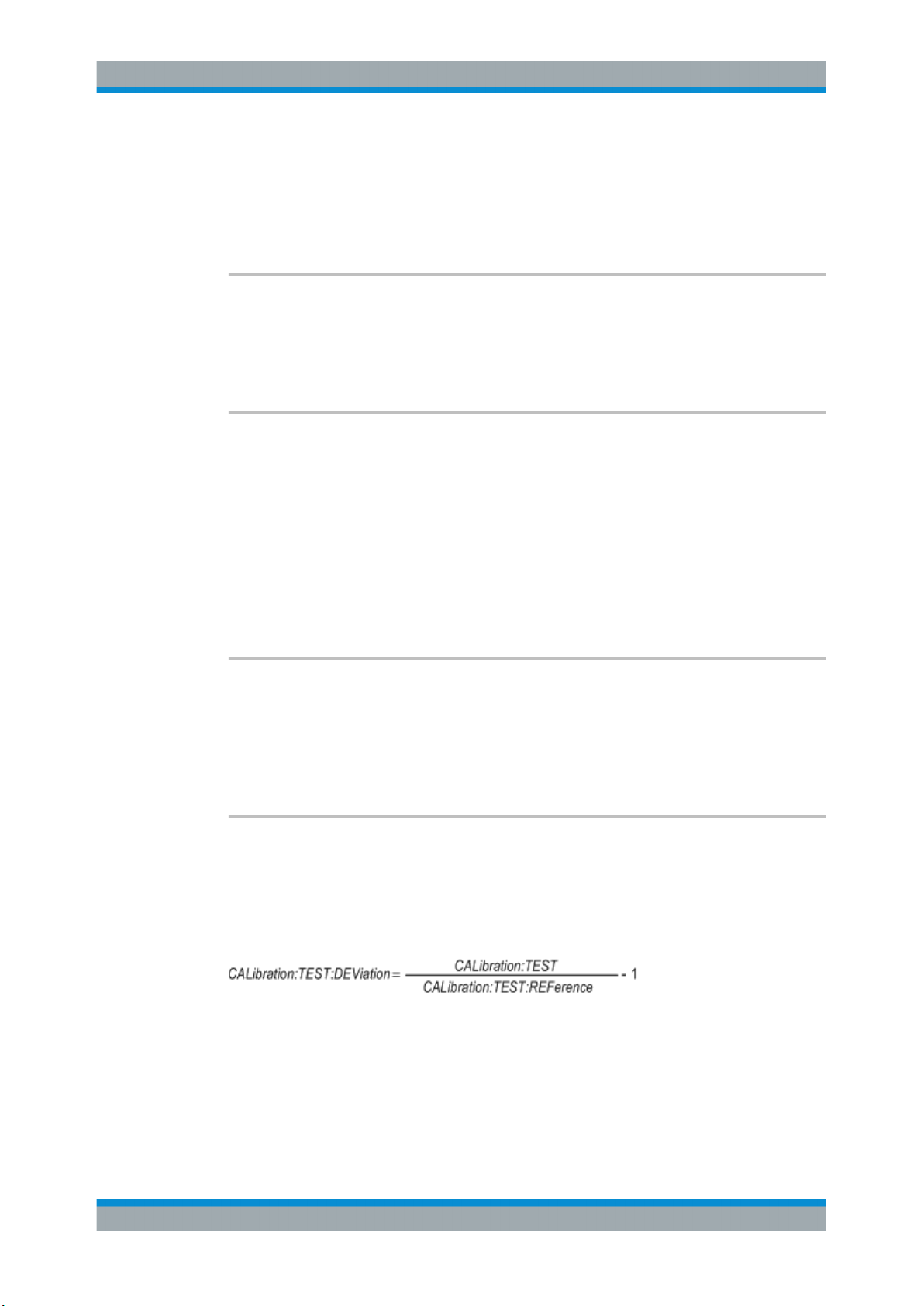
R&S®NRPxxTWG
Remote Control Commands
Calibrating/Zeroing the Power Sensor
CALibration:TEST:DEViation?........................................................................................... 79
CALibration:TEST:REFerence?......................................................................................... 80
CALibration:USER:DATA.................................................................................................. 80
CALibration:USER:DATA:LENGth?....................................................................................80
CALibration<Channel>:ZERO:AUTO..................................................................................80
CALibration:DATA <caldata>
Writes a binary calibration data set in the memory of the sensor.
Parameters:
<caldata> <block_data>
CALibration:DATA:LENGth?
Queries the length in bytes of the calibration data set currently stored in the flash memory. Programs that read out the calibration data set can use this information to determine the capacity of the buffer memory required.
Example:
CAL:DATA:LENG?
Query
57392
Response
Usage: Query only
CALibration:TEST?
The thermal sensors are equipped with an additional test heater. This query returns the
power difference in W between the states when the external heater is switched on and
when it is switched off.
Usage:
Query only
CALibration:TEST:DEViation?
Determines the power difference in W between the state when the external heater is
switched on and when it is switched off.
The relative deviation of the power difference from the reference value stored during
calibration is output which is calculated as follows:
Usage:
Query only
79User Manual 1178.8371.02 ─ 04
Page 80
R&S®NRPxxTWG
Remote Control Commands
Calibrating/Zeroing the Power Sensor
CALibration:TEST:REFerence?
During the calibration process, the power difference in W between the state when the
external heater is switched on and when it is switched off is determined and stored in
the calibration data set. This query returns the value stored at the time of calibration.
Usage: Query only
CALibration:USER:DATA <caldata>
Accesses the user calibration data block.
Parameters:
<caldata> <block_data>
CALibration:USER:DATA:LENGth?
Queries the length of the user calibration data block.
Usage:
CALibration<Channel>:ZERO:AUTO <state>
Performs zero calibration.
Turn off all test signals before zeroing. An active test signal during zeroing causes an
error.
While zero calibration is in progress, no queries or other setting commands are
allowed, since the command is synchronous. Any communication attempt can run into
a timeout.
After zero calibration, query the static error queue (SYSTem:SERRor?). The following
responses are possible:
0
●
No error, the zero calibration was successful.
-240
●
Warning, zero calibration failed. See also the example.
Suffix:
<Channel>
Parameters:
<state> ONCE
Query only
.
1...4
Measurement channel if more than one channel is available.
Only valid parameter for this command.
0
Return value if no calibration is in progress.
*RST: OFF
80User Manual 1178.8371.02 ─ 04
Page 81
R&S®NRPxxTWG
Remote Control Commands
Configuring the System
Example:
*CLS
CAL1:ZERO:AUTO ONCE
Performs zeroing. Takes several seconds.
SYST:SERR?
Query
-240
Response: Warning; Zero Calibration failed; Results Degrading.
7.10 Testing the Power Sensor
The selftest allows a test of the internal circuitry of the sensor.
Do not apply a signal to the sensor while the selftest is running. If the selftest is carried
out with a signal being present, error messages can erroneously be output for the test
steps Offset Voltages and/or Noise Voltages.
TEST:SENSor? [<Item>]
Triggers a selftest of the sensor. In contrast to *TST?, this command returns detailed
information that you can use for troubleshooting.
Query parameters:
<Item> String
Usage: Query only
7.11 Configuring the System
The SYSTem subsystem contains a series of commands for general functions that do
not directly affect the measurement.
The SYSTem:COMMunicate:NETWork:... commands are only available for the
R&S NRP LAN power sensors.
Remote commands:
SYSTem:COMMunicate:NETWork:RESTart........................................................................ 82
SYSTem:COMMunicate:NETWork:RESet...........................................................................82
SYSTem:COMMunicate:NETWork:STATus?....................................................................... 83
SYSTem:COMMunicate:NETWork[:COMMon]:DOMain........................................................83
SYSTem:COMMunicate:NETWork[:COMMon]:HOSTname...................................................83
SYSTem:COMMunicate:NETWork:IPADdress..................................................................... 84
SYSTem:COMMunicate:NETWork:IPADdress:GATeway.......................................................84
SYSTem:COMMunicate:NETWork:IPADdress:INFO?...........................................................84
SYSTem:COMMunicate:NETWork:IPADdress:MODE.......................................................... 84
81User Manual 1178.8371.02 ─ 04
Page 82
R&S®NRPxxTWG
Remote Control Commands
Configuring the System
SYSTem:COMMunicate:NETWork:IPADdress:SUBNet:MASK.............................................. 85
SYSTem:DFPRint<Channel>?...........................................................................................85
SYSTem:ERRor:ALL?.......................................................................................................85
SYSTem:ERRor:CODE:ALL?............................................................................................ 85
SYSTem:ERRor:CODE[:NEXT]?........................................................................................86
SYSTem:ERRor:COUNt?..................................................................................................86
SYSTem:ERRor[:NEXT]?..................................................................................................86
SYSTem:FWUPdate.........................................................................................................87
SYSTem:FWUPdate:STATus?...........................................................................................87
SYSTem:HELP:HEADers?................................................................................................ 87
SYSTem:HELP:SYNTax?..................................................................................................87
SYSTem:HELP:SYNTax:ALL?........................................................................................... 88
SYSTem:INFO?............................................................................................................... 88
SYSTem:INITialize........................................................................................................... 89
SYSTem:LANGuage.........................................................................................................89
SYSTem:LED:COLor........................................................................................................89
SYSTem:LED:MODE........................................................................................................90
SYSTem:MINPower?........................................................................................................90
SYSTem:PARameters?.....................................................................................................90
SYSTem:PARameters:DELTa?.......................................................................................... 90
SYSTem:PRESet............................................................................................................. 91
SYSTem:REBoot..............................................................................................................91
SYSTem:RESTart.............................................................................................................91
SYSTem:RUTime.............................................................................................................91
SYSTem:SERRor?........................................................................................................... 91
SYSTem:SERRor:LIST:ALL?.............................................................................................92
SYSTem:SERRor:LIST[:NEXT]?........................................................................................92
SYSTem:SUTime.............................................................................................................92
SYSTem:TLEVels?...........................................................................................................92
SYSTem:TRANsaction:BEGin........................................................................................... 92
SYSTem:TRANsaction:END..............................................................................................93
SYSTem[:SENSor]:NAME.................................................................................................93
SYSTem:VERSion?..........................................................................................................93
SYSTem:COMMunicate:NETWork:RESTart
Effective only for the R&S NRP LAN power sensors.
Restarts the network connection to the DUT, that means terminates the connection and
sets it up again.
Example:
SYST:COMM:NETW:REST
Usage: Event
SYSTem:COMMunicate:NETWork:RESet
Effective only for the R&S NRP LAN power sensors.
Resets the LAN network settings to the default values.
Usage:
Event
82User Manual 1178.8371.02 ─ 04
Page 83
R&S®NRPxxTWG
Remote Control Commands
Configuring the System
SYSTem:COMMunicate:NETWork:STATus?
Effective only for the R&S NRP LAN power sensors.
Queries the network configuration state.
Example:
Usage: Query only
SYSTem:COMMunicate:NETWork[:COMMon]:DOMain
Effective only for the R&S NRP LAN power sensors.
Sets the domain of the network.
Parameters:
<domain>
Example:
SYSTem:COMMunicate:NETWork[:COMMon]:HOSTname <hostname>
Effective only for the R&S NRP LAN power sensors.
Sets the individual hostname of the sensor.
SYST:COMM:NETW:STAT?
Query
UP
Response: The network is active.
<domain>
SYST:COMM:NETW:COMM:DOM 'ABC.DE'
Sets ABC.DE as domain of the network.
In a LAN that uses a DNS server (domain name system server), you can access each
connected instrument using a unique hostname instead of its IP address. The DNS
server translates the hostname to the IP address. Using a hostname is especially useful if a DHCP server is used, as a new IP address can be assigned each time the
instrument is restarted.
The sensor performs the change of the hostname immediately after the command is
sent. For this purpose, the sensor restarts its connection to the network, which can
take several seconds. During this time, you cannot address the sensor. After the
restart, you can only address the sensor using the newly set hostname.
Note: It is recommended that you do not change the default hostname to avoid problems with the network connection. However, if you change the hostname, be sure to
use a unique name.
Parameters:
<hostname>
Example:
SYST:COMM:NETW:COMM:HOST
'powersensor-2nd-floor'
Sets powersensor-2nd-floor as new hostname.
83User Manual 1178.8371.02 ─ 04
Page 84
R&S®NRPxxTWG
Remote Control Commands
Configuring the System
SYSTem:COMMunicate:NETWork:IPADdress <ipaddress>
Effective only:
●
For the R&S NRP LAN power sensors.
●
If SYSTem:COMMunicate:NETWork:IPADdress:MODE is set to STATic.
Sets the IP address of the sensor.
Parameters:
<ipaddress>
Example:
SYSTem:COMMunicate:NETWork:IPADdress:GATeway <gateway>
Effective only:
●
For the R&S NRP LAN power sensors.
●
If SYSTem:COMMunicate:NETWork:IPADdress:MODE is set to STATic.
Sets the IP address of the default gateway.
Parameters:
<gateway>
Example:
SYSTem:COMMunicate:NETWork:IPADdress:INFO?
Effective only for the R&S NRP LAN power sensors.
Queries the network status information.
Usage:
SYST:COMM:NETW:IPAD '192.168.10.29'
Sets 192.168.10.29 as IP address.
SYST:COMM:NETW:IPAD:GAT '192.168.10.254'
Sets 192.168.10.254 as IP address of the default gateway.
Query only
SYSTem:COMMunicate:NETWork:IPADdress:MODE <mode>
Effective only for the R&S NRP LAN power sensors.
Sets whether the IP address is assigned automatically or manually.
Parameters:
<mode> AUTO | STATic
AUTO
Assigns the IP address automatically, provided the network supports DHCP.
STATic
Enables assigning the IP address manually.
*RST: AUTO
84User Manual 1178.8371.02 ─ 04
Page 85
R&S®NRPxxTWG
Remote Control Commands
Configuring the System
Example:
SYSTem:COMMunicate:NETWork:IPADdress:SUBNet:MASK <netmask>
Effective only:
●
For the R&S NRP LAN power sensors.
●
If SYSTem:COMMunicate:NETWork:IPADdress:MODE is set to STATic.
Sets the subnet mask.
Parameters:
<netmask>
Example:
SYSTem:DFPRint<Channel>?
Reads the footprint file of the sensor.
Suffix:
<Channel>
SYST:COMM:NETW:IPAD:MODE AUTO
The IP address is assigned automatically.
SYST:COMM:NETW:IPAD:SUBN:MASK '255.255.255.0'
Sets 255.255.255.0 as subnet mask.
.
1...4
Measurement channel if more than one channel is available.
Usage: Query only
SYSTem:ERRor:ALL?
Queries all unread entries in the error/event queue and removes them from the queue.
The response is a comma-separated list in first out order, each entry consisting of the
error number and a short description of the error.
Positive error numbers are instrument-dependent. Negative error numbers are
reserved by the SCPI standard.
Example:
Usage: Query only
SYSTem:ERRor:CODE:ALL?
Queries all unread entries in the error/event queue and removes them from the queue.
Only the error numbers are returned.
SYST:ERR:ALL?
Query
0,"No error"
Response
85User Manual 1178.8371.02 ─ 04
Page 86
R&S®NRPxxTWG
Remote Control Commands
Configuring the System
Example:
Usage: Query only
SYSTem:ERRor:CODE[:NEXT]?
Queries the oldest entry in the error queue and then deletes it. Only the error number
is returned.
Example:
Usage: Query only
SYSTem:ERRor:COUNt?
Queries the number of entries in the error queue.
SYST:ERR:CODE:ALL?
Query
0
Response: No errors have occurred since the error queue was
last read out.
SYST:ERR:CODE?
Query
0
Response: No errors have occurred since the error queue was
last read out.
Example:
Usage: Query only
SYSTem:ERRor[:NEXT]?
Queries the error/event queue for the oldest entry and removes it from the queue. The
response consists of an error number and a short description of the error.
Positive error numbers are instrument-dependent. Negative error numbers are
reserved by the SCPI standard.
Example:
Usage: Query only
SYST:ERR:COUN?
Query
1
Response: One error has occurred since the error queue was
last read out.
SYST:ERR?
Query
0, 'no error'
Response: No errors have occurred since the error queue was
last read out.
86User Manual 1178.8371.02 ─ 04
Page 87
R&S®NRPxxTWG
Remote Control Commands
Configuring the System
SYSTem:FWUPdate <fwudata>
Loads new operating firmware into the power sensor. Rohde & Schwarz provides the
update file. For further details, see Chapter 6, "Firmware Update", on page 31.
If you want to integrate a firmware update function in an application, see the example
given in Chapter 6.2.2, "Using Remote Control", on page 33.
Setting parameters:
<fwudata> <block_data>
Definite length arbitrary block data containing the direct copy of
the binary *.rsu file in the following format:
#
Single digit indicating how many digits follow to specify the size
of the binary file.
Number that specifies the size of the binary file.
Binary data
0x0a as appended delimiter for line feed
Usage: Setting only
SYSTem:FWUPdate:STATus?
Reads the result of the firmware update performed using SYSTem:FWUPdate
on page 87.
While a firmware update is in progress, the LED of the sensor flashes in bright white
color. When the firmware update is completed, you can read the result.
The result of the query is a readable string.
Example:
Usage: Query only
SYSTem:HELP:HEADers? [<Item>]
Returns a list of all SCPI commands supported by the sensor.
Query parameters:
<Item> <block_data>
Usage: Query only
SYST:FWUP:STAT?
Query
"Success"
Response
SYSTem:HELP:SYNTax? [<Item>]
Queries the relevant parameter information for the specified SCPI command.
Query parameters:
<Item>
87User Manual 1178.8371.02 ─ 04
Page 88

R&S®NRPxxTWG
Remote Control Commands
Configuring the System
Example:
Usage: Query only
SYSTem:HELP:SYNTax:ALL?
Queries the implemented SCPI commands and their parameters. Returns the result as
a block data.
Usage: Query only
SYSTem:INFO? [<item>]
Queries information about the system.
If queried without parameters, the command returns all available information in the
form of a list of strings separated by commas.
If you want to query specific information, add a query parameter.
Query parameters:
<item> "<string>" with the following values:
SYST:HELP:SYNT? 'sens:aver:coun'
Manufacturer
Type
Stock Number
Serial
SW Build
MAC Address
Hostname
IP Address
Domain
Subnetmask
Gateway
Mode
Status
Sensor Name
Technology
Function
MinPower
MaxPower
MinFreq
MaxFreq
Resolution
Impedance
Coupling
88User Manual 1178.8371.02 ─ 04
Page 89
R&S®NRPxxTWG
Remote Control Commands
Configuring the System
Uptime
Cal. Misc.
Cal. Abs.
Cal. Refl.
Cal. Temp.
Cal. Lin.
Cal. S-Para.
Cal. S-Para. (User)
SPD Mnemonic
Cal. Due Date
Certificate No
Limit
TestLimit
TestLimit pd
Usage:
SYSTem:INITialize
Sets the sensor to the standard state, i.e. the default settings for all test parameters
are loaded in the same way as with *RST. The sensor then outputs a complete list of
all supported commands and parameters. With the command, the remote-control software can automatically adapt to the features of different types of sensors with different
functionality.
Usage:
SYSTem:LANGuage <language>
Selects an emulation of a different command set.
Parameters:
<language> SCPI
SYSTem:LED:COLor <color>
Query only
Event
*RST: SCPI
Sets the color and the flash code of the system status LED, if the operating mode of
the LED is set to USER (SYSTem:LED:MODE).
Parameters:
<color> Hexadecimal code described as
0x0krrggbb
with
k = 0: steady on; k = 1: slowly flashing; k = 2: fast flashing
rr = red
gg = green
89User Manual 1178.8371.02 ─ 04
Page 90
R&S®NRPxxTWG
Remote Control Commands
Configuring the System
bb = blue
Range: 0x00 to 0x02FFFFFF
*RST: 0x00A0A0A0
Example:
SYSTem:LED:MODE <mode>
Sets whether the color of the system status LED is controlled by the sensor firmware or
by the user settings.
For more information, see SYSTem:LED:COLor.
Parameters:
<mode> USER | SENSor
SYSTem:MINPower?
SYST:LED:MODE USER
Sets the system status LED operating mode to user.
SYST:LED:COL #H01a00000
The LED flashes slowly in red.
SYSTem:LED:MODE SENSor
Sets the system status LED operating mode back to the sensor
internal settings.
*RST: SENSor
Queries the lower power measurement limit.
This value changes if [SENSe<Sensor>:]CORRection:SPDevice:STATe is set to
ON. The lower measurement limit refers to the sensor or to the combination of a sensor
and the components connected ahead of it.
Use this query to determine a useful resolution for the result display near the lower
measurement limit.
Usage:
SYSTem:PARameters?
Lists all commands with default values, limits and ranges.
Usage:
SYSTem:PARameters:DELTa?
Lists all commands that differ from the defined default status set by *RST on page 39.
The commands are output with default values, limits and ranges.
Usage:
Query only
Query only
Query only
90User Manual 1178.8371.02 ─ 04
Page 91
R&S®NRPxxTWG
Remote Control Commands
Configuring the System
SYSTem:PRESet
Triggers a sensor reset.
The command essentially corresponds to the *RST command, with the exception that
the settings of the following commands are persistently held:
INITiate:CONTinuous
SENSe:AVERage:TCONtrol
Usage: Event
SYSTem:REBoot
Reboots the sensor.
Usage:
SYSTem:RESTart
Restarts the firmware of the R&S NRPxxTWG.
Usage:
SYSTem:RUTime <update_time>
Effective only in the NRP legacy mode.
Sets the result update time. That is the maximum rate in which the power sensor can
output measurement results. Relevant only in continuous measurement mode
(INITiate:CONTinuous ON).
Parameters:
<update_time> Range: 0.0 to 10.0
SYSTem:SERRor?
Event
Event
*RST: 0.1
Default unit: Seconds
Queries the next static error, if available. Static errors are more severe than normal
error conditions, which can be queried using SYSTem:ERRor[:NEXT]?.
Normal errors result from, for example, unknown commands or syntax errors and generally affect a single parameter or setting. Static errors, as a rule, prevent the execution
of normal measurements.
Usage:
Query only
91User Manual 1178.8371.02 ─ 04
Page 92
R&S®NRPxxTWG
Remote Control Commands
Configuring the System
SYSTem:SERRor:LIST:ALL?
Returns a list of all static errors that have occurred but have already been resolved.
For example, an overload of a short duration.
Example:
Usage: Query only
SYSTem:SERRor:LIST[:NEXT]?
Queries the list of all static errors that have occurred but have already been resolved
for the oldest entry and removes it from the queue. The response consists of an error
number and a short description of the error.
Example:
Usage: Query only
SYST:SERR:LIST:ALL?
Response: 0,"reported at uptime:2942; notice;
auto-averaging exceeded maximum time;
Notification",0,"removed at uptime:2944;
notice; auto-averaging exceeded maximum time;
Notification".
SYST:SERR:LIST?
Query
0,"reported at uptime:2942; notice;
auto-averaging exceeded maximum time;
Notification"
Response
SYSTem:SUTime <update_time>
Effective only in the NRP legacy mode.
Sets the status update time. That is the maximum rate in which the power sensor can
output measurement results. Relevant only in continuous measurement mode
(INITiate:CONTinuousON).
Parameters:
<update_time> Range: 0.0 to 10.0
*RST: 10e-3
Default unit: Seconds
SYSTem:TLEVels?
Queries the possible power test levels of the sensor.
Usage:
SYSTem:TRANsaction:BEGin
Starts a series of settings.
Query only
92User Manual 1178.8371.02 ─ 04
Page 93
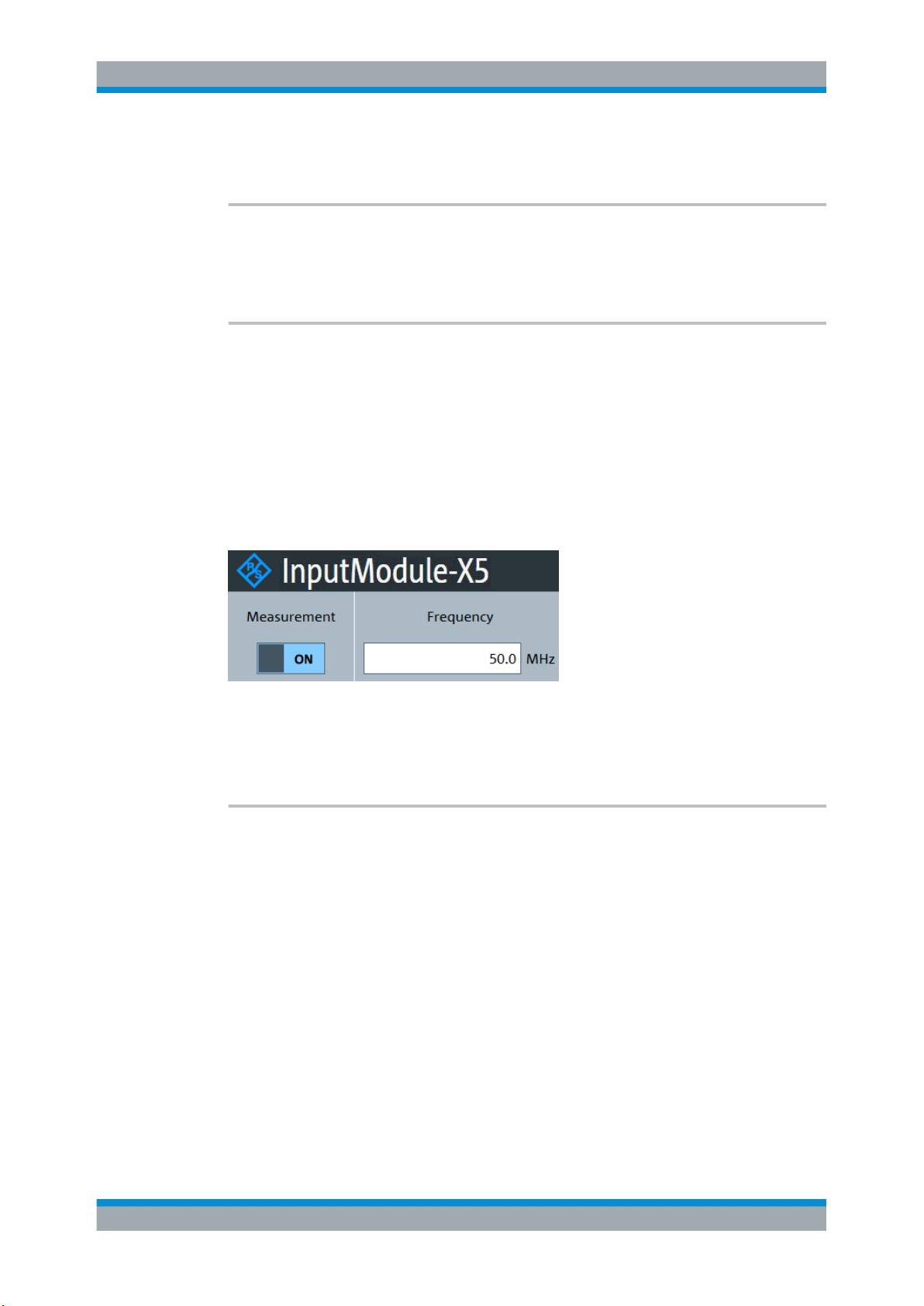
R&S®NRPxxTWG
Remote Control Commands
Using the Status Register
Usage: Event
SYSTem:TRANsaction:END
Ends a series of settings.
Usage: Event
SYSTem[:SENSor]:NAME <sensorname>
Sets the name of the sensor according to your requirements. The specified name is
displayed in the web user interface of the network sensors.
The sensor name that you specify here is independent from the hostname of the sensor. However, if the sensor name is not specified, it defaults to the hostname.
Example:
SYST:NAME "InputModule-X5"
Results in a display as shown in Figure 7-7.
Figure 7-7: Sensor Name
Parameters:
<sensorname>
SYSTem:VERSion?
Queries the SCPI version that the command set of the sensor complies with.
Example:
Usage: Query only
SYST:VERS?
Query
1999.0
Response: SCPI version from 1999.
7.12 Using the Status Register
Further information:
●
Chapter 9.3, "Status Reporting System", on page 107
93User Manual 1178.8371.02 ─ 04
Page 94
R&S®NRPxxTWG
7.12.1 General Status Register Commands
Remote Control Commands
Using the Status Register
Contents:
● General Status Register Commands...................................................................... 94
● Reading Out the CONDition Part............................................................................ 94
● Reading Out the EVENt Part...................................................................................95
● Controlling the ENABle Part....................................................................................95
● Controlling the Negative Transition Part................................................................. 95
● Controlling the Positive Transition Part...................................................................96
STATus:PRESet...............................................................................................................94
STATus:QUEue[:NEXT]?.................................................................................................. 94
STATus:PRESet
Resets the edge detectors and ENABle parts of all registers to a defined value.
Usage:
STATus:QUEue[:NEXT]?
Queries the most recent error queue entry and deletes it.
Positive error numbers indicate sensor specific errors. Negative error numbers are
error messages defined by SCPI.
If the error queue is empty, the error number 0, "No error", is returned.
Usage:
Event
Query only
7.12.2 Reading Out the CONDition Part
Further information:
●
Chapter 9.3.2, "Structure of a SCPI Status Register", on page 108
STATus:DEVice:CONDition?
STATus:OPERation:CALibrating:CONDition?
STATus:OPERation:CONDition?
STATus:OPERation:LLFail:CONDition?
STATus:OPERation:MEASuring:CONDition?
STATus:OPERation:SENSe:CONDition?
STATus:OPERation:TRIGger:CONDition?
STATus:OPERation:ULFail:CONDition?
STATus:QUEStionable:CALibration:CONDition?
STATus:QUEStionable:CONDition?
STATus:QUEStionable:POWer:CONDition?
STATus:QUEStionable:WINDow:CONDition?
Usage:
Query only
94User Manual 1178.8371.02 ─ 04
Page 95
R&S®NRPxxTWG
7.12.3 Reading Out the EVENt Part
Remote Control Commands
Using the Status Register
Further information:
●
Chapter 9.3.2, "Structure of a SCPI Status Register", on page 108
STATus:DEVice[:EVENt]?
STATus:OPERation:CALibrating[:SUMMary][:EVENt]?
STATus:OPERation[:EVENt]?
STATus:OPERation:LLFail[:SUMMary][:EVENt]?
STATus:OPERation:MEASuring[:SUMMary][:EVENt]?
STATus:OPERation:SENSe[:SUMMary][:EVENt]?
STATus:OPERation:TRIGger[:SUMMary][:EVENt]?
STATus:OPERation:ULFail[:SUMMary][:EVENt]?
STATus:QUEStionable:CALibration[:SUMMary][:EVENt]?
STATus:QUEStionable[:EVENt]?
STATus:QUEStionable:POWer[:SUMMary][:EVENt]?
STATus:QUEStionable:WINDow[:SUMMary][:EVENt]?
Usage:
Query only
7.12.4 Controlling the ENABle Part
Further information:
●
Chapter 9.3.2, "Structure of a SCPI Status Register", on page 108
STATus:DEVice:ENABle <value>
STATus:OPERation:CALibrating:ENABle <value>
STATus:OPERation:ENABle <value>
STATus:OPERation:LLFail:ENABle <value>
STATus:OPERation:MEASuring:ENABle <value>
STATus:OPERation:SENSe:ENABle <value>
STATus:OPERation:TRIGger:ENABle <value>
STATus:OPERation:ULFail:ENABle <value>
STATus:QUEStionable:CALibration:ENABle <value>
STATus:QUEStionable:ENABle <value>
STATus:QUEStionable:POWer:ENABle <value>
STATus:QUEStionable:WINDow:ENABle <value>
Parameters:
<value> *RST: 0
7.12.5 Controlling the Negative Transition Part
Further information:
●
Chapter 9.3.2, "Structure of a SCPI Status Register", on page 108
STATus:DEVice:NTRansition <value>
STATus:OPERation:CALibrating:NTRansition <value>
STATus:OPERation:NTRansition <value>
95User Manual 1178.8371.02 ─ 04
Page 96
R&S®NRPxxTWG
7.12.6 Controlling the Positive Transition Part
Remote Control Commands
Using the Status Register
STATus:OPERation:LLFail:NTRansition <value>
STATus:OPERation:MEASuring:NTRansition <value>
STATus:OPERation:SENSe:NTRansition <value>
STATus:OPERation:TRIGger:NTRansition <value>
STATus:OPERation:ULFail:NTRansition <value>
STATus:QUEStionable:CALibration:NTRansition <value>
STATus:QUEStionable:NTRansition <value>
STATus:QUEStionable:POWer:NTRansition <value>
STATus:QUEStionable:WINDow:NTRansition <value>
Parameters:
<value> *RST: 0
Further information:
●
Chapter 9.3.2, "Structure of a SCPI Status Register", on page 108
STATus:DEVice:PTRansition <value>
STATus:OPERation:CALibrating:PTRansition <value>
STATus:OPERation:PTRansition <value>
STATus:OPERation:LLFail:PTRansition <value>
STATus:OPERation:MEASuring:PTRansition <value>
STATus:OPERation:SENSe:PTRansition <value>
STATus:OPERation:TRIGger:PTRansition <value>
STATus:OPERation:ULFail:PTRansition <value>
STATus:QUEStionable:CALibration:PTRansition <value>
STATus:QUEStionable:PTRansition <value>
STATus:QUEStionable:POWer:PTRansition <value>
STATus:QUEStionable:WINDow:PTRansition <value>
Parameters:
<value> *RST: 65535
96User Manual 1178.8371.02 ─ 04
Page 97

R&S®NRPxxTWG
8 Performing Measurement Tasks - Program-
8.1 Performing the Simplest Measurement
Performing Measurement Tasks - Programming Examples
Performing a Buffered Continuous Average Measurement
ming Examples
If you install the optional software development kit (SDK) of the R&S NRP Toolkit, programming examples are provided. See Chapter 5.1, "R&S NRP Toolkit", on page 19.
Under Windows, these examples are installed under:
C:\ProgramData\Rohde-Schwarz\NRP-Toolkit-SDK\examples
Programming example for performing measurement tasks with the series power sensors are given in the following chapter.
The simplest way to obtain a result is to use the following sequence of commands:
*RST
INITiate
FETCh?
The *RST sets the Continuous Average mode.
INITiate initiates the measurement.
After *RST, the trigger system is set to TRIGger:SOURce IMMediate so that the
trigger system state changes to the measuring state via the waiting for trigger state.
After the measurement has been completed, FETCh? delivers the result to the output
queue from which it can be fetched.
8.2 Performing a Buffered Continuous Average Measurement
This example, written in pseudo code, shows how to setup and execute a buffered
continuous average measurement.
//Select whether using
// 'BUS Trigger' --> true
// or 'EXT Trigger' --> false
bool bUseBUSTrigger = true;
// Use the first NRP series sensor which is found
if ( VI_SUCCESS == SENSOR.openFirstNrpSensor( "USB?::0X0AAD::?*::INSTR" ) )
{
//Start with a clean state
SENSOR.write( "*RST" );
97User Manual 1178.8371.02 ─ 04
Page 98

R&S®NRPxxTWG
Performing Measurement Tasks - Programming Examples
Performing a Buffered Continuous Average Measurement
// Auto Averaging OFF and set Average Count = 4
SENSOR.write( "SENS:AVER:COUN:AUTO OFF" );
SENSOR.write( "SENS:AVER:COUN 4" );
// Select the trigger source
if ( bUseBUSTrigger )
{
// We want to use '*TRG' to trigger a single physical measurement
SENSOR.write( "TRIG:SOUR BUS" );
}
else
{
// We get trigger pulses on the external input (SMB-type connector)
SENSOR.write( "TRIG:SOUR EXT2" );
}
// Auto-Trigger OFF
SENSOR.write( "TRIG:ATR:STAT OFF" );
// Configure a buffered measurement
// Buffer size is randomly selected to 17
SENSOR.write( "SENS:BUFF:SIZE 17" );
SENSOR.write( "SENS:BUFF:STAT ON" );
SENSOR.write( "TRIG:COUN 17" );
// Read out all errors / Clear error queue
SENSOR.query( "SYST:ERR:ALL?", szBuf, sizeof( szBuf ) );
printf( szBuf );
// Start a 'single' buffered measurement
// Since 17 trigger-counts have been configured,
// the 'single' buffered measurement, which becomes
// initiated by INIT:IMM, is not over until
// 17 physical measurements have been triggered
SENSOR.write( "INIT:IMM" );
// The end of a physical measurement can be recognized
// by a transistion to 'NOT MEASURING' which is a
// negative transistion on bit 1
SENSOR.write( "STAT:OPER:MEAS:NTR 2" );
SENSOR.write( "STAT:OPER:MEAS:PTR 0" );
// Collect 17 physical measurements
for ( int i = 0; i < 17; i++ )
{
// As a pre-condition: clear the event register by reading it
int iDummy;
SENSOR.query( "STAT:OPER:MEAS:EVEN?", &iDummy );
98User Manual 1178.8371.02 ─ 04
Page 99

R&S®NRPxxTWG
Performing Measurement Tasks - Programming Examples
Performing a Buffered Continuous Average Measurement
// Trigger a single physical measurement; either by '*TRG'
// command or by an externally supplied pulse on the SMB-type connector
if ( bUseBUSTrigger )
SENSOR.write( "*TRG" );
// Wait until the measurement is done
int iMeasEvent = 0;
while ( iMeasEvent != 2 )
{
SENSOR.query( "STAT:OPER:MEAS:EVEN?", &iMeasEvent );
iMeasEvent &= 2;
}
printf( "Triggered!\n" );
}
// All 17 physical measurement have been executed.
// That means, buffer is full and can be read
SENSOR.query( "FETCH?", szBuf, sizeof( szBuf ) );
printf( szBuf );
}
99User Manual 1178.8371.02 ─ 04
Page 100
R&S®NRPxxTWG
9 Remote Control Basics
9.1 Remote Control Interfaces and Protocols
Remote Control Basics
Remote Control Interfaces and Protocols
● Remote Control Interfaces and Protocols............................................................. 100
● SCPI Command Structure.....................................................................................101
● Status Reporting System...................................................................................... 107
For remote control, communication between the R&S NRPxxTWG power sensors and
the controlling host is established based on various interfaces and protocols.
Depending on the sensor type, the power sensors support different interfaces for
remote control.
●
R&S NRPxxTWG power sensors are always accessed using USB.
Table 9-1 describes the protocols that are supported for each interface.
Table 9-1: Remote control interfaces and protocols
Interface Supported by
USB All
power
sensors
(*) VISA is a standardized software interface library providing input and output functions to communicate with instruments. A VISA
installation on the controller is a prerequisite for remote control over USBTMC and LAN (when using VXI-11 or HiSLIP protocol)
interfaces.
Protocols, VISA*) address string and Library
●
USBTMC
USB::<vendor ID>::<product ID>::<serial number>[::INSTR]
VISA
●
NRP legacy protocol
9.1.1 USB Interface
For remote control using USB connection, the computer and the power sensors must
be connected via the USB interface. A USB connection requires the VISA library to be
installed. VISA detects and configures the R&S power sensors automatically when the
USB connection is established. Apart from the USBTMC driver (which comes with the
installation of the R&S NRP Toolkit), you do not have to install a separate driver.
USB Test & Measurement Class Specification (USBTMC) is a protocol that is built on
top of USB for communication with USB devices. It defines class code information of
the sensor, that identifies its functionality to load the respective device driver. Using
VISA library, it supports service request, triggers and other operations that are commonly found in GPIB devices.
Besides USBTMC, the NRP legacy protocol is available to ensure the compatibility of
the R&S NRPxxTWG power sensors with the R&S NRP‑Z series of power sensors.
The usage of this protocol is not recommended for new applications.
The resource string represents an addressing scheme that is used to establish a communication session with the sensor. It is based on the sensor address and some instrument- and vendor-specific information.
100User Manual 1178.8371.02 ─ 04
 Loading...