

Page 1
®
R&S
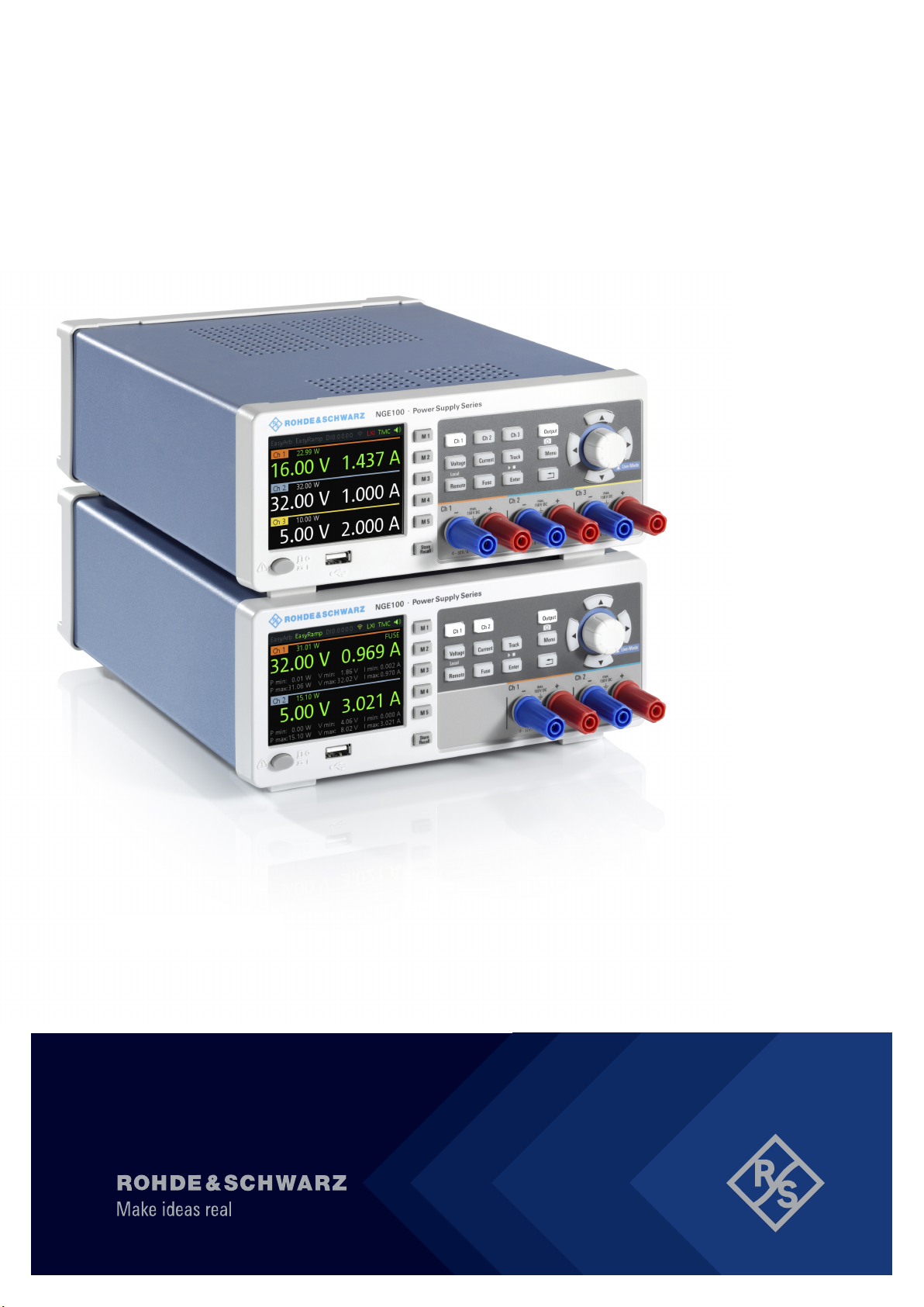
NGE100B
Power Supply
Getting Started
(Æ1=U2)
5601133702
Version 08
Page 2

This manual describes the following R&S®NGE100B models and options:
●
R&S®NGE102B 2-Channel PSU (5601.3800.02)
●
R&S®NGE103B 3-Channel PSU (5601.3800.03)
The contents of this manual correspond to firmware version 1.50 or higher.
© 2022 Rohde & Schwarz GmbH & Co. KG
Muehldorfstr. 15, 81671 Muenchen, Germany
Phone: +49 89 41 29 - 0
Email: [email protected]
Internet: www.rohde-schwarz.com
Subject to change – data without tolerance limits is not binding.
R&S® is a registered trademark of Rohde & Schwarz GmbH & Co. KG.
Trade names are trademarks of the owners.
5601.1337.02 | Version 08 | R&S®NGE100B
Throughout this manual, products from Rohde & Schwarz are indicated without the ® symbol, e.g.
R&S®NGE100B is indicated as R&S NGE100B.
Page 3

R&S®NGE100B
Contents
1 Safety information................................................................. 5
2 Korea certification class A....................................................6
3 Documentation overview...................................................... 7
3.1 Manuals..................................................................................................7
3.2 Data sheet..............................................................................................7
3.3 Calibration certificate........................................................................... 8
3.4 Release notes, open source acknowledgment.................................. 8
4 Welcome to R&S NGE100B...................................................9
Contents
5 Putting into operation......................................................... 10
5.1 Safety................................................................................................... 11
5.2 Intended operation..............................................................................13
5.3 Unpacking and checking the instrument..........................................15
5.4 Setting up the instrument.................................................................. 16
5.4.1 Bench operation....................................................................................16
5.4.2 Rack mounting...................................................................................... 17
6 Instrument tour.................................................................... 18
6.1 Overview of controls.......................................................................... 18
6.1.1 Front panel............................................................................................18
6.1.2 Rear panel............................................................................................ 20
6.2 Switching on the instrument..............................................................22
7 Trying out the instrument................................................... 24
7.1 Selecting the channels....................................................................... 24
7.2 Setting the output voltage and current limit.................................... 24
3Getting Started 5601.1337.02 ─ 08
Page 4

R&S®NGE100B
7.3 Activating the channels output......................................................... 25
7.4 Storing/Recalling of instrument settings..........................................25
Contents
8 Maintenance and support................................................... 26
8.1 Maintenance........................................................................................ 26
8.2 Contacting customer support............................................................26
Index..................................................................................... 28
4Getting Started 5601.1337.02 ─ 08
Page 5

R&S®NGE100B
Safety information
1 Safety information
The product documentation helps you use the R&S NGE100B safely and efficiently. Follow the instructions provided here and in the printed "Basic Safety
Instructions". Keep the product documentation nearby and offer it to other users.
Intended use
The R&S NGE100B is intended for the development, production and verification
of electronic components and devices in industrial, administrative, and laboratory
environments. Use the R&S NGE100B only for its designated purpose. Observe
the operating conditions and performance limits stated in the data sheet.
Where do I find safety information?
Safety information is part of the product documentation. It warns you about the
potential dangers and gives instructions how to prevent personal injuries or damage caused by dangerous situations. Safety information is provided as follows:
●
The printed "Basic Safety Instructions" provide safety information in many languages and are delivered with the R&S NGE100B.
●
Throughout the documentation, safety instructions are provided when you
need to take care during setup or operation.
5Getting Started 5601.1337.02 ─ 08
Page 6

R&S®NGE100B
Korea certification class A
2 Korea certification class A
이 기기는 업무용(A급) 전자파 적합기기로서 판매자 또는 사용자는 이 점을 주의하
시기 바라며, 가정외의 지역에서 사용하는 것을 목적으로 합니다.
6Getting Started 5601.1337.02 ─ 08
Page 7

R&S®NGE100B
Documentation overview
Data sheet
3 Documentation overview
This section provides an overview of the R&S NGE100B user documentation.
3.1 Manuals
You find the documents on the R&S NGE100B product page at:
www.rohde-schwarz.com/product/nge100b
Getting started
Introduces the R&S NGE100B power supply series and describes how to set up
and start working with the instrument. The printed document is delivered with the
instrument.
User manual
Contains the description of all instrument modes and functions. It also provides
an introduction to remote control, a complete description of the remote control
commands with programming examples, and information on maintenance and
instrument interfaces. Includes the contents of the getting started manual.
The online version of the user manual provides the complete contents for immediate display on the internet.
Basic safety instructions
Contains safety instructions, operating conditions and further important information. The printed document is delivered with the instrument.
3.2 Data sheet
The datasheet contains the technical specifications of the R&S NGE100B power
supply series. It also lists all options with their order numbers and accessories.
See www.rohde-schwarz.com/brochure-datasheet/nge100b
7Getting Started 5601.1337.02 ─ 08
Page 8

R&S®NGE100B
Release notes, open source acknowledgment
Documentation overview
3.3 Calibration certificate
The document is available on https://gloris.rohde-schwarz.com/calcert. You need
the device ID of your instrument, which you can find on a label on the rear panel.
3.4 Release notes, open source acknowledgment
The release notes list new features, improvements and known issues of the current firmware version, and describe the firmware installation. The open source
acknowledgment document provides verbatim license texts of the used open
source software. It can also be downloaded from the instrument.
See www.rohde-schwarz.com/firmware/nge100b.
8Getting Started 5601.1337.02 ─ 08
Page 9

R&S®NGE100B
Welcome to R&S NGE100B
4 Welcome to R&S NGE100B
The two or three-channel power supply series are based on a classical transformer concept with high efficiency electronic pre-regulators and secondary linear
regulators. This concept allows the instrument to achieve the high output power
within a minimum space, high efficiency and lowest residual ripple.
The R&S NGE100B power supply series feature galvanically isolated, floating
overload and short-circuit proof outputs with adjustable power ratings. The outputs can be connected in series or in parallel, thus making high currents and voltages available.
Multi-purpose protection functions are available for each channel which you can
set separately, such as overcurrent protection (FUSE), overvoltage protection
(OVP), overpower protection (OPP) and overtemperature protection (OTP). If
such a limit is reached, the affected output channel is automatically turned off and
an indicator message (FUSE, OVP, OPP or OTP) is displayed. The overcurrent
protection can be linked to other channel (FuseLink function). In this case, all
linked channels are turned off when the set channel reaches its limit.
The EasyArb function allows channel 1 (Ch 1) to have freely definable voltage
and current sequences with a timeframe as short as 10 ms. It allows you to vary
the voltage or current limit during a test sequence, for example to simulate different charging conditions of a battery. With EasyRamp function, the R&S NGE100B
provides the operating condition to simulate the continuous rise of the supply voltage within a defined timeframe of 10 ms to 10 s.
Four data lines of the digital I/O interface are mutually independent and can be
used as trigger input or trigger output separately. Various trigger conditions (e.g.
fuse tripped, voltage, current, indicator messages) can be used to turn off, on or
invert the output state when the trigger condition is met.
All R&S NGE100B power supply series are equipped with a color LCD display
(320 x 240 pixels resolution). The R&S NGE100B comes with a USB interface
and optional LAN (LXI) interface.
This user manual contains a description of the functionalities that the instrument
provides. The latest version is available for download at the product homepage
(http://www.rohde-schwarz.com/product/nge100b).
9Getting Started 5601.1337.02 ─ 08
Page 10
R&S®NGE100B
Putting into operation
5 Putting into operation
This chapter describes the steps to set up the R&S NGE100B for the first time.
Risk of injury and instrument damage
The instrument must be used in an appropriate manner to prevent electric
shock, fire, personal injury, or damage.
●
Do not open the instrument casing
●
Read and observe the "Basic Safety Instructions" delivered as a printed
brochure with the instrument. Note that the basic safety instructions also
contain information on operating conditions that prevent damage to the
instrument
In addition, read and observe the safety instructions in the following sections. Notice that the data sheet may specify additional operating conditions.
Risk of instrument damage during operation
An unsuitable operating site or test setup can cause damage to the instrument and the connected devices. Ensure the following operating conditions
before you switch on the instrument:
●
The instrument is dry and shows no sign of condensation
●
The instrument is positioned as described in Chapter 5.4.1, "Bench
operation", on page 16
●
The ambient temperature does not exceed the range specified in the
data sheet
●
Voltage levels at the input connectors are all within the specified ranges
●
Voltage outputs are correctly connected and not overloaded
10Getting Started 5601.1337.02 ─ 08
Page 11
R&S®NGE100B
Risk of radio interference
This is a class A product. In a domestic environment, this product may
cause radio interference in which case the user may be required to take
adequate measures.
EMI impact on measurement results
Electromagnetic interference (EMI) may affect the measurement results.
To suppress the generated EMI:
●
Use suitable shielded cables of high quality, for example, LAN cables
●
Note the EMC classification in the data sheet
Putting into operation
Safety
● Safety.............................................................................................................. 11
● Intended operation.......................................................................................... 13
● Unpacking and checking the instrument......................................................... 15
● Setting up the instrument................................................................................ 16
5.1 Safety
Recommendations on secure operation
The R&S NGE100B is designed to operate at local workplaces or in
secured networks (LAN). It should not be accessible from the internet,
because of a potential security risk, e.g. attackers could misuse or damage
your device.
Please always install the latest firmware.
It is highly recommended that you work closely with your IT department or
system administrator to ensure compliance with your company policies
when connecting devices to your company's network.
This instrument was built in compliance with DIN EN 61010-1 (VDE 0411 part 1),
safety regulations for electrical instruments, control units and Iaboratory equip-
11Getting Started 5601.1337.02 ─ 08
Page 12
R&S®NGE100B
ment. It has been tested and shipped from the plant in safe condition. It is also in
compliance with the regulations of the European standard EN 61010-1 and the
international standard IEC 61010-1.
To maintain this condition and ensure safe operation, you must observe all
instructions and warnings given in this user manual. Casing, chassis and all measuring ports are connected to a protective earth conductor. The instrument is
designed in compliance with the regulations of protection class I.
For safety reasons, the instrument may only be operated with authorized safety
sockets. The power cord must be plugged in before signal circuits may be connected.
Never use the product if the power cable is damaged. Check regularly that the
power cables are in perfect condition. Choose suitable protective measures and
installation types to ensure that the power cord cannot be damaged and that no
harm is caused by tripping hazards or from electric shock, for instance.
Putting into operation
Safety
Risk of electric shock
It is prohibited to disconnect the earthed protective connection inside or outside of the instrument!
If it is assumed that a safe operation is no longer possible, the instrument must be
shut down and secured against any unintended operation.
Safe operation can no longer be assumed as follows:
●
Instrument shows visible damage
●
Instrument includes loose parts
●
Instrument no longer functions properly
– After an extended period of storage under unfavorable conditions (e.g. out-
doors or in damp rooms)
– After rough handling during transport (e.g. packaging that does not meet
the minimum requirements by post office, railway or forwarding agency)
12Getting Started 5601.1337.02 ─ 08
Page 13
R&S®NGE100B
Exceeding the low voltage protection
Use insulated wires and not bare wires for the terminal connection.
For the series connection of all output voltages, it is possible to exceed the
low voltage protection of 42 V. Please note that in this case any contact with
live components is life-threatening. It is assumed that only qualified and
trained personnel service the power supplies and the connected loads.
Before switching on the product, it must be ensured that the nominal voltage setting on the product matches the nominal voltage of the AC supply network. If it is
necessary to set a different voltage, the power fuse of the product must be
changed accordingly.
Putting into operation
Intended operation
5.2 Intended operation
The instrument is intended only for use by personnel familiar with the potential
risks of measuring electrical quantities.
For safety reasons, the instrument may only be connected to properly installed
safety socket outlets. Separating the ground is prohibited.
The power plug must be inserted before signal circuits may be connected.
Use only the power cord included in the delivery package. See "Delivery
package" on page 15.
Before each measurement, measuring cables must be inspected for damage and replaced if necessary. Damaged or worn components can damage
the instrument or cause injury.
The product may be operated only under the operating conditions and in the positions specified by the manufacturer, without the product's ventilation being
obstructed. If the manufacturer’s specifications are not observed, this can result
in electric shock, fire and/or serious personal injury, and in some cases, death.
13Getting Started 5601.1337.02 ─ 08
Page 14
R&S®NGE100B
Putting into operation
Intended operation
Provide adequate airflow
Do not block the air intake at the front and side of the instrument or the exhaust at
the rear. Install the instrument on a location that allows sufficient space for air circulation at the air intake and exhaust. Recommended spacing to non-heat producing surface is at least 2.5 inches (63.5 mm) from the ventilation holes.
Applicable local or national safety regulations and rules for the prevention of accidents must be observed in all work performed.
The instrument is designed for use in the following sectors: Industrial, residential,
business and commercial areas and small businesses.
The instrument is designed for indoor use only. Before each measurement, you
need to verify at a known source if the instrument functions properly.
To disconnect from the mains, the low-heat device socket on the back panel
has to be unplugged.
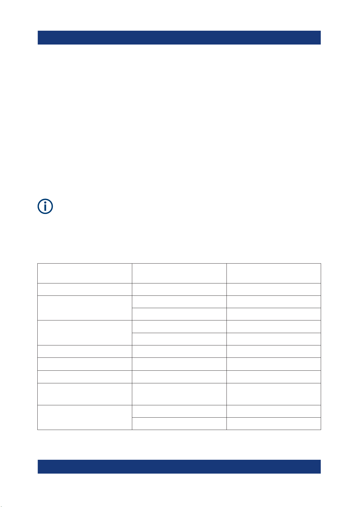
See Table 5-1 for the general data on the instrument specification. For more infor-
mation, see the instrument product brochure (PN: 5214.8748.12).
Table 5-1: General data on instrument specification
Mains nominal voltage AC 115 V / 230 V (±10 %) 50 Hz /
60 Hz
Power consumption Maximum input power 180 W
Mains fuses
(fuse size: 5 mm x 20 mm)
Temperature Operating temperature range 0 °C to + 40 °C
Humidity Non-condensing 5 % to 80 %
Display
Rack mount capability ½ 19 " R&S HZC95 option
Dimensions W x H x D 222 mm x 88 mm x 280 mm
115 V AC IEC 60127-2/5 T 5 A 250 V
230 V AC IEC 60127-2/5 T 2.5 A 250 V
Storage temperature range - 20 °C to + 70 °C
3.5 " (QVGA)
(8.74 in x 3.46 in x 11.02 in)
Weight R&S NGE102B 4.9 kg (10.80 lb)
R&S NGE103B 5.0 kg (11.02 lb)
14Getting Started 5601.1337.02 ─ 08
Page 15
R&S®NGE100B
Unpacking and checking the instrument
Putting into operation
5.3 Unpacking and checking the instrument
Check the equipment for completeness using the delivery note and package contents list for the various items. Check the instrument for any damage and loose
parts. If there is any damage, immediately contact the carrier who delivered the
instrument.
Packing material
Retain the original packing material. If the instrument needs to be transported or shipped at a later date, you can use the material to protect the control
elements and connectors.
Risk of damage during transportation and shipment
Insufficient protection against mechanical and electrostatic effects during
transportation and shipment can damage the instrument.
●
Always ensure that sufficient mechanical and electrostatic protections
are provided
●
When shipping an instrument, the original packaging should be used. If
you do not have the original packaging, use sufficient padding to prevent the instrument from moving around inside the box. Pack the instrument in antistatic wrap to protect it from electrostatic charging
●
Secure the instrument to prevent any movement and other mechanical
effects during transportation
Delivery package
The package contents contain the following items:
●
R&S NGE100B power supply preloaded with two 230 V fuses
●
Four power cables
●
Two 115 V fuses (replace the preloaded fuses with these fuses depending on
the mains voltage, see Chapter 6.2, "Switching on the instrument",
on page 22 for more information)
●
One 5-pin plug (P/N: 3643.6463.00) for digital I/O port connections
●
One Getting Started manual
15Getting Started 5601.1337.02 ─ 08
Page 16
R&S®NGE100B
●
One document folder containing Basic Safety instructions guide and CE certificate
Putting into operation
Setting up the instrument
5.4 Setting up the instrument
The R&S NGE100B is designed for benchtop and rackmount.
5.4.1 Bench operation
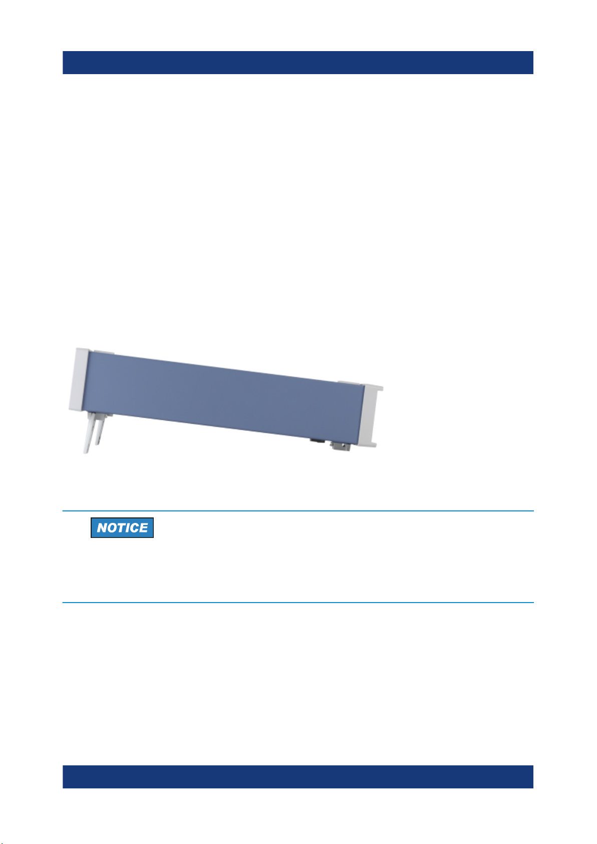
On a benchtop, the R&S NGE100B can either lie flat or stand on its feet. As
shown in Figure 5-1, feet on the bottom can be folded out to set the instrument in
an inclined position.
Figure 5-1: Operating positions
Positioning of instrument
The instrument must be positioned in a manner that allows the user to disconnect the unit from the mains at any time and without restrictions.
16Getting Started 5601.1337.02 ─ 08
Page 17
R&S®NGE100B
Risk of injury if feet are folded out
The feet can fold in if they are not folded out completely or if the instrument
is shifted. Collapsing feet can cause injury or damage the instrument.
●
Fold the feet completely in or out to ensure stability of the instrument.
Never shift the instrument when the feet are folded out.
●
When the feet are folded out, do not work under the instrument or place
anything underneath.
●
The feet can break if they are overloaded. The overall load on the folded-out feet must not exceed 250 N.
5.4.2 Rack mounting
Putting into operation
Setting up the instrument
The instrument can be installed in a 19" rack-mount using a rack adapter kit.
Ambient temperature
Operate R&S NGE100B power supply in an area where the ambient temperature is within +0 °C to +40 °C. The R&S NGE100B power supply is fancooled and must be installed with sufficient space along the sides to allow
proper air circulation. Ensure that fan openings are unobstructed and airflow vents are unimpeded.
Operating the instrument with insufficient airflow or outside the allowable
ambient temperature can disrupt the operation and even cause damage.
17Getting Started 5601.1337.02 ─ 08
Page 18
R&S®NGE100B
Instrument tour
Overview of controls
6 Instrument tour
This chapter provides an overview of all the controls available in the R&S
NGE100B models and steps to switch on the instrument for the first time.
6.1 Overview of controls
6.1.1 Front panel
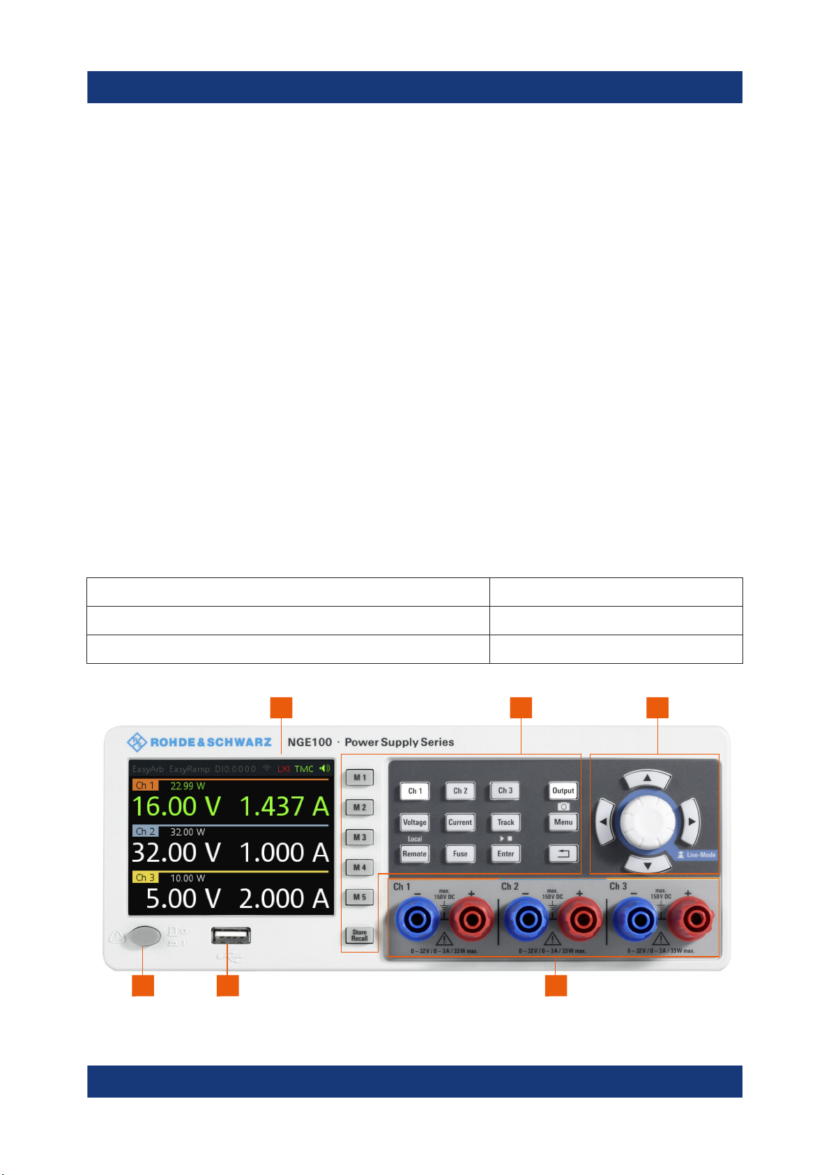
The front panel of the R&S NGE100B is as shown in Figure 6-1. The function
keys and navigation controls are located at the right side of the display. The various connectors are located below the display and function keys.
The following power supply models are available:
Table 6-1: Power supply models
Models Number of output channels
R&S NGE102B (0 V - 32 V/3 A) 2 (maximum 66 W)
R&S NGE103B (0 V - 32 V/3 A) 3 (maximum 100 W)
1 2 3
Figure 6-1: Front panel of R&S NGE100B with 3 channels
456
18Getting Started 5601.1337.02 ─ 08
Page 19

R&S®NGE100B
Instrument tour
Overview of controls
1 = Display
2 = Function keys
3 = Rotary knob and arrow keys
4 = Output channels (see Table 6-1)
5 = USB connector
6 = Power key
Display (1)
The display is a color LCD screen. Depending on the instrument models, up to
three channels are shown on the screen. The respective measurement settings
and functions are displayed in the individual channel section. There is a status
bar above the channel section to indicate the function used and operation mode
of the instrument.
For a detailed description on-screen layout, see section "Screen Layout" in the
User Manual.
Function keys (2)
Function keys are means of input for manual operation of the instrument functions. When a function key is pressed, all the related keys are also illuminated.
For detailed description on function keys, see section "Function Keys" in the User
Manual.
Rotary knob and arrow keys (3)
Rotary knob and arrow keys are means of navigation and adjustment. When
pressed or rotated, they perform tasks like navigation around the screen, adjustment of parameter values or confirmation of entries.
For detailed description on rotary knob and arrow keys, see section "Navigation
Controls" in the User Manual.
Output channels (4)
Depending on the instrument models, up to three output channels are available
for output of power to the connected load. See Table 6-1.
USB connector (5)
USB Type-A connector is provided for connecting a USB flash drive to perform
firmware update and store screen captures.
The USB flash drive file system supports FAT32 only.
19Getting Started 5601.1337.02 ─ 08
Page 20
R&S®NGE100B
Instrument tour
Overview of controls
Power key (6)
The [Power] key switches the instrument on and off.
6.1.2 Rear panel
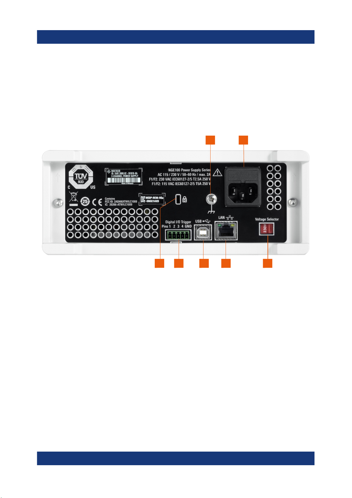
Figure 6-2 shows the rear panel of the R&S NGE100B with its connectors.
7 8
910111213
Figure 6-2: Rear panel of R&S NGE100B
7 = Ground terminal
8 = AC inlet with fuse holder
9 = Voltage selector
10 = Ethernet (LAN) connector
11 = USB connector
12 = Digital I/O connector
13 = Kensington lock
Ground terminal (7)
M4 screw provides connection to earth ground through the instrument ground/
chassis.
20Getting Started 5601.1337.02 ─ 08
Page 21
R&S®NGE100B
Instrument tour
Overview of controls
AC inlet with fuse holder (8)
Main supply cord
Do not use detachable mains supply cord with inadequate rating.
For safety reasons, the instrument can only be operated with authorized safety
sockets.
The power cable must be plugged in before signal circuits can be connected.
Never use the product if the power cable is damaged. See Chapter 6.2, "Switch-
ing on the instrument", on page 22 for more information.
Voltage selector (9)
Setting voltage selector
The voltage selector is located at the bottom of the R&S NGE100B.
On your first power-on connection, a yellow label sticker is attached over
the AC inlet. Before peeling off the yellow label sticker, make sure the correct fuse rating is used for the mains voltage.
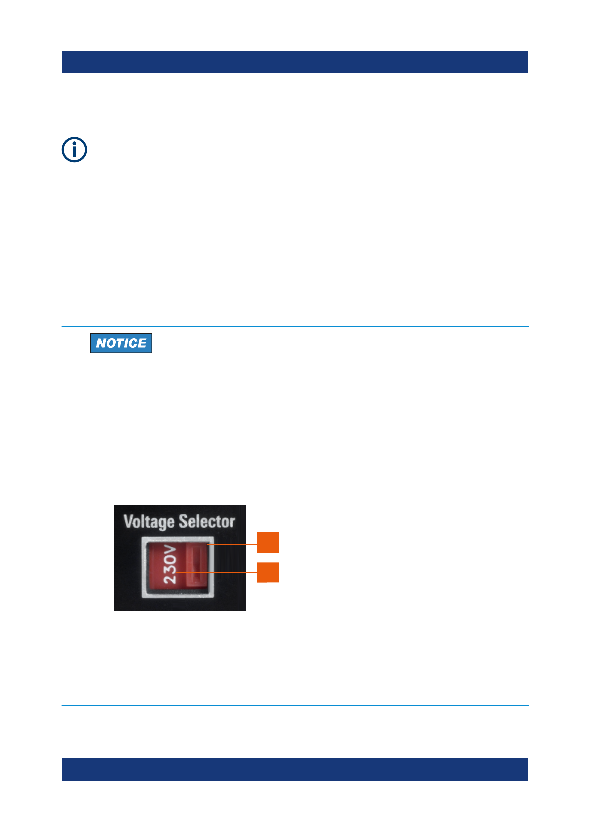
To set the correct fuse rating, slide the selector according to the voltage
selector label.
1
2
Figure 6-3: Voltage selector
1 = Voltage selector
2 = Voltage selector label
21Getting Started 5601.1337.02 ─ 08
Page 22

R&S®NGE100B
Switching on the instrument
The voltage selector selects the mains voltage between 115 V and 230 V. See
Table 5-1 for the fuse rating.
Ethernet connector (10)
This connector is used for establishing remote control via SCPI or LXI. See section "Ethernet Setup" in the user manual for more information on the connection
setup.
The Ethernet option R&S NGE-K101 must be installed for this function to be
available in the instrument.
USB connector (11)
The USB connector is a Type-B connector for remote control operation via USB
TMC or USB VCP.
Instrument tour
Digital I/O connector (12)
The Digital I/O connector is a 5-pin terminal block for external trigger input or output.
Measurement control can be achieved by means of an external input signal or as
an output signal to trigger other instruments for some measurements.
The Digital Trigger I/O option (R&S NGE-K103) must be installed for this function
to be available in the instrument.
Kensington security slot (13)
A Kensington lock can be anchored to the R&S NGE100B power supply housing
to secure it to a workstation mechanically.
6.2 Switching on the instrument
Before switching on the instrument, check that all the instructions in the “Basic
Safety Instruction” brochure and safety measures in previous sections are
observed.
Also, check if the value on the voltage selector corresponds to the mains voltage
(115 V or 230 V).
22Getting Started 5601.1337.02 ─ 08
Page 23

R&S®NGE100B
Switching on the instrument
To change the power fuse / mains voltage setting:
1. Peel off the yellow label sticker on the AC inlet.
2. Pull out the fuse holder which is located directly on top of the socket.
3. Remove the preloaded fuses from the fuse holder.
4. Check the rating on the caps of both fuses that you want to change.
For more information, see "Setting voltage selector" on page 21.
5. Once verified, insert the fuses into each groove of the fuse holder.
6. Return the fuse holder to its position in the panel.
To switch on the instrument:
1. Connect the power cable to the AC power connector on the rear panel of the
R&S NGE100B.
Instrument tour
2. Connect the power cable to the socket outlet.
3. Press [Power] key on the front panel.
The instrument performs a system check, boots the operating system and
starts the R&S NGE100B firmware.
By default, all output channels are turned off when the instrument is switched
on to prevent connected loads from being damaged unintentionally.
During startup, the R&S NGE100B is loaded with the last saved instrument
settings from memory location "M1" and auto saved parameters. See "Store
and Recall" in the User Manual.
To switch off instrument:
1. Press [Power] key.
2. Disconnect the AC power cable from the socket outlet.
23Getting Started 5601.1337.02 ─ 08
Page 24

R&S®NGE100B
Setting the output voltage and current limit
Trying out the instrument
7 Trying out the instrument
This chapter describes some basic functions that you can perform with the R&S
NGE100B.
7.1 Selecting the channels
To select a channel, press the corresponding channel key. The key illuminates.
7.2 Setting the output voltage and current limit
To set the output voltage and current limit via Live-Mode:
1. Long press the rotary knob to enter into editing mode.
By default, the voltage at channel 1 is selected.
2. Use arrow keys to select the desired parameter (voltage or current).
3. Rotate the rotary knob to adjust value.
4. To exit Live-Mode, press the rotary knob.
Alternatively:
1. Press [Voltage] or [Current] key on the front panel.
2. Press the desired channel key to activate the respective voltage or current
limit setting of that channel. The value on the respective channel becomes
editable and is positioned by a blue cursor.
3. Press the [Left] or [Right] arrow key to move the cursor.
4. Press the [Up]/[Down] arrow key or turn the rotary knob to change the value.
The new value registers immediately.
24Getting Started 5601.1337.02 ─ 08
Page 25

R&S®NGE100B
Storing/Recalling of instrument settings
Trying out the instrument
7.3 Activating the channels output
The output voltages can be switched on or off regardless of the operating mode
of the instrument.
To activate the channel output, press the [Output] key on the front panel followed
by the desired channel key or vice versa.
Depending on the instrument operating mode, the display font color changes to
green in CV (constant voltage) mode and red in CC (constant current) mode.
7.4 Storing/Recalling of instrument settings
The instrument settings can be stored in the instrument memory by long pressing
the [Store Recall] key followed by the desired memory location key ([M1] to [M5]).
The previous saved settings are overwritten.
To retrieve the settings, press [Store Recall] key and select the desired memory
location key ([M1] to [M5]).
25Getting Started 5601.1337.02 ─ 08
Page 26
R&S®NGE100B
Maintenance and support
Contacting customer support
8 Maintenance and support
8.1 Maintenance
Regular maintenance improves the life span of the instrument, the following chapter provides information on instrument maintenance.
Cleaning
Before cleaning the instrument, ensure that it has been switched off and the
power cable is disconnected.
Clean the outer case of the instrument at regular intervals, using a soft, lint-free
dust cloth.
Instrument damage caused by cleaning agents
Use a dry, lint-free cloth to clean the product. When cleaning, keep in mind
that the casing is not waterproof. Do not use any liquids for cleaning.
Cleaning agents, solvents (thinners, acetone), acids and bases can damage the front panel labeling, plastic parts and display.
The display may only be cleaned with an appropriate glass cleaner. Rub the display with a dry, clean and lint-free cloth. Do not allow cleaning fluid to enter the
instrument.
8.2 Contacting customer support
Technical support – where and when you need it
For quick, expert help with any Rohde & Schwarz product, contact our customer
support center. A team of highly qualified engineers provides support and works
with you to find a solution to your query on any aspect of the operation, programming or applications of Rohde & Schwarz products.
26Getting Started 5601.1337.02 ─ 08
Page 27
R&S®NGE100B
Maintenance and support
Contacting customer support
Contact information
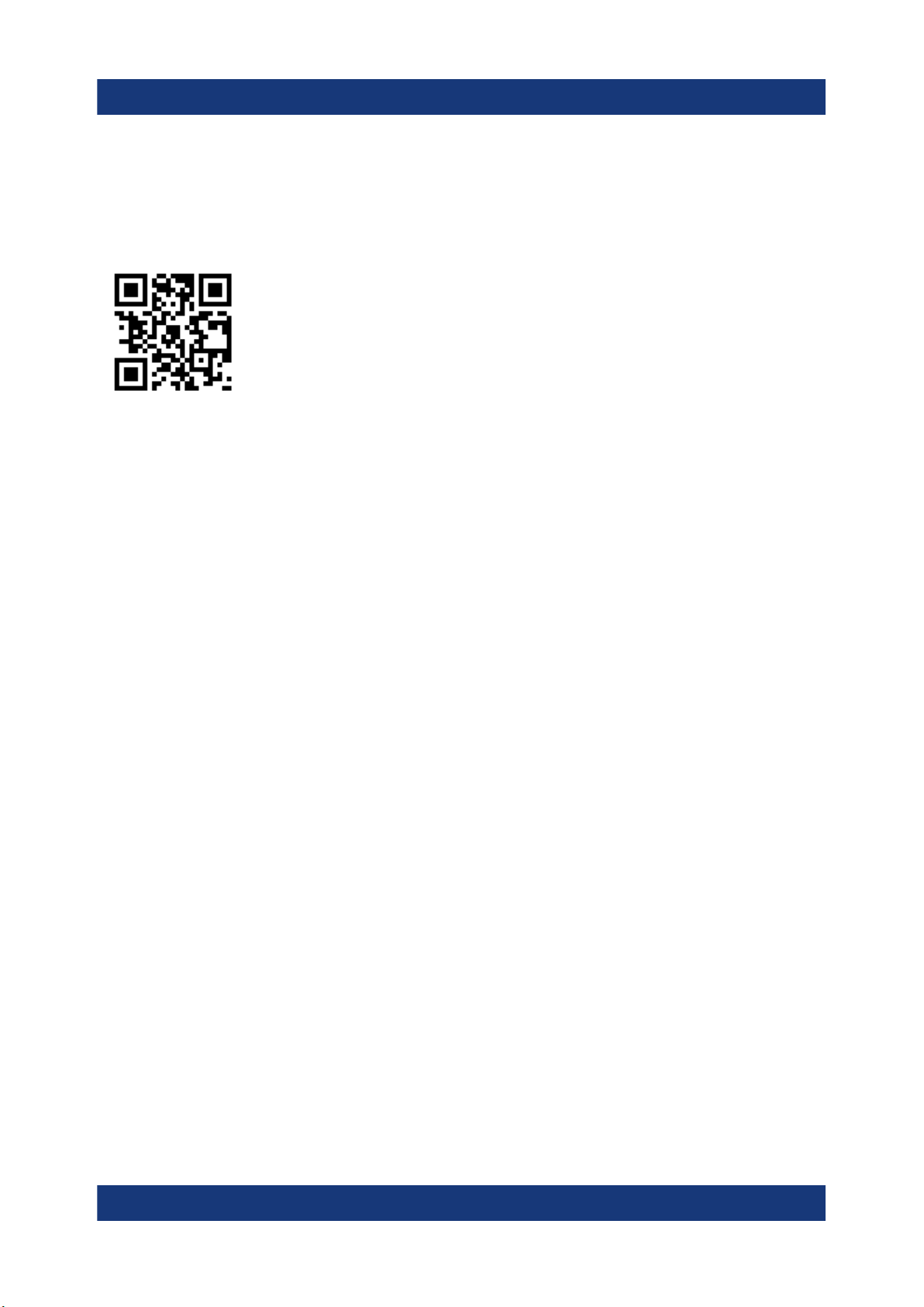
Contact our customer support center at www.rohde-schwarz.com/support, or fol-
low this QR code:
Figure 8-1: QR code to the Rohde & Schwarz support page
27Getting Started 5601.1337.02 ─ 08
Page 28

R&S®NGE100B
Index
Index
C
Calibration certificate .................................8
Controls ................................................... 18
Customer support ....................................26
D
Data sheet ................................................. 7
Documentation overview ........................... 7
F
Front panel
Display ................................................ 18
Function keys ......................................18
Output channels ..................................18
Power key ........................................... 18
Rotary knob and arrow keys ............... 18
USB connector ....................................18
G
Getting started ...........................................7
I
Setting up the instrument
Bench operation ..................................16
Rack mounting ....................................16
Switching off the instrument .................... 22
Switching on the instrument .................... 22
T
Trying out the instrument
Activating the channels output ............24
Selecting the channels ........................24
Setting the output voltage and Current
limit ..................................................... 24
Storing/Recalling of instrument settings
............................................................ 24
U
Unpacking and checking the instrument . 15
User manual .............................................. 7
Intended use ..............................................5
M
Maintenance
Cleaning ..............................................26
O
Open source acknowledgment (OSA) .......8
P
Package contents ....................................15
R
Rear panel
AC inlet with fuse holder ..................... 20
Digital I/O connector ........................... 20
Ethernet connector ............................. 20
USB connector ....................................20
Voltage selector .................................. 20
Release notes ........................................... 8
S
Safety information ..................................... 5
Safety instructions ..................................... 7
28Getting Started 5601.1337.02 ─ 08
 Loading...