

Page 1
¸HMC8015
Power Analyzer
User Manual
*5800532402*
5800532402
User Manual
Version 01
Test & Measurement
Page 2
General Information Regarding the CE Marking
General Information Regarding the CE Marking
General Information Regarding the CE Marking
All ROHDE & SCHWARZ measuring instruments comply
with the regulations of the EMC directive. The ROHDE &
SCHWARZ conformity evaluation is based on applicable
professional and product standards. In cases where
multiple limit values can be used, ROHDE & SCHWARZ
will apply the stricter standard of the two. With regard to
interference emission, the limit values for businesses and
commercial operations including the small business sector
are applied (Class 1B). For the susceptibility to interference
emissions, the applicable limit values for the industrial sector are used. The signal and data cables that must be connected to the device during operation will necessarily affect
the compliance with the acceptance limits to some extent.
However, the cables used for this purpose will vary, depending on the application. For operation of the device, the following information and conditions should therefore be observed
with regard to interference emission and susceptibility:
1. Data Cables
All connections between measuring instruments or their
interfaces and external devices (printers, computers, etc.)
must always be implemented with adequately shielded
cables. Unless the user manual species a shorter maximum
cable length, the data cable (input/output, signal/control) may
not exceed a total length of 3 m, and may not be located
outdoors. If the device interface allows the connection of
more than one cable, only one may be connected at a time.
Data cables in general should always be double-shielded
cable. For the IEEE bus cable, the double-shielded cable
HZ72 is recommended and can be ordered from ROHDE &
SCHWARZ.
2. Signal Cables
Signal cables used for signal transmission between the
measurement point and the measuring device should generally be kept as short as possible. Unless a shorter maximum
cable length is specied, the signal cables (input/output,
signal/control) may not exceed a total length of 1 m, and may
not be located outdoors. All signal cables must be shielded
(RG58/U coaxial cable). Care must be taken to achieve a
proper ground connection. For signal generators, doubleshielded coaxial cables (RG223/U, RG214/U) must always be
used.
General Information
3. Impact on the Equipment
In the presence of strong high-frequency electric or
magnetic elds, unwanted signal components may enter
the equipment, despite careful setup of the connected
cables and lines. With ROHDE & SCHWARZ measuring
instruments, this will neither be destructive nor lead to the
shutdown of the equipment. As a result of such external
conditions, the displayed values and readings may show
minor deviations with respect to the applicable instrument
specications in individual cases.
Regarding the
CE Marking
2
2
Page 3

Content
General Information Regarding the CE Marking .... 2
1 Important Information ...................4
1.1 Symbols ...................................4
1.2 Unpacking ..................................4
1.3 Instrument Setup ............................4
1.4 Safet y .....................................4
1.5 Intended Use ...............................4
1.6 Ambient Conditions ..........................5
1.7 Warranty and Repair ..........................5
1.8 Maintenance ................................5
1.9 CAT II ......................................6
1.10 Supply Voltage ..............................6
1.11 Limit Values .................................6
1.12 Batteries and Accumulators/Cells ...............6
1.13 Product Disposal .............................7
2 Instrument Controls and Indicators .........8
3 Options/Upgrade Vouchers ............... 9
4 Connecting a Device under Test .......... 10
4.1 Connecting a Device under Test via Adapter ......10
4.2 Connecting a Device under Test Directly .........11
4.3 Sensor Menu ...............................12
5 Setting Parameters ..................... 13
5.1 Using the Instrument for the First Time ..........13
5.2 Screen Display Description ...................13
5.3 Multifunction Softkeys .......................14
5.4 Conguring the Operating Mode from a List of
Measuring Parameter Options (“Cells”) ..........14
5.5 Readout Display ............................14
5.6 Selecting the Measuring Range ................15
6 Instrument Functions ................... 16
6.1 Measurement Parameters ....................16
6.2 Display Modes (VIEW Menu) ..................16
6.3 Crest Factor ................................19
6.4 Energy Counter (Integrator Values) .............19
6.5 Invert Function .............................20
6.6 Acquisition Mode ...........................20
6.7 Peak Hold .................................21
6.8 Limits .....................................21
6.9 Analog / Digital Inputs and Outputs .............21
7 Data Logging .........................23
8 Documenting, Saving and Retrieving ....... 25
8.1 Device Settings .............................25
9 General Settings ....................... 26
9.1 Updates (Instrument Firmware) ................26
9.2 Interface Setup .............................26
9.3 General Settings (Misc). ......................26
10 Remot Operation ......................28
10.1 USB VCP ..................................28
10.2 USB TMC .................................28
10.3 Ethernet ...................................30
10.4 IEEE 488.2 / GPIB ...........................32
11 Technical Data ........................33
12 Appendix ............................34
12.1 List of gures ..............................34
12. 2 Glos sar y ..................................34
Content
Content
3
3
Page 4
Important Information
Important Information
1 Important
Information
1.1 Symbols
must follow the instructions and warnings contained in
this manual carefully. The enclosure, chassis and all
measuring terminals are connected to protective ground
lead. The device complies with protection class II.
Disabling or separating the intended safety ground
connection, either inside or outside the device, is not
permitted!
(1) (2) (3) (4)
(5) (6) (7)
Symbol 1: CAUTION: General hazard –
Observe product documentation
Symbol 2: Danger of electric shock
Symbol 3: Earth (ground)
Symbol 4: Protective conductor terminal
Symbol 5: ON (supply voltage)
Symbol 6: OFF (supply voltage)
Symbol 7: Ground terminal
1.2 Un packing
When unpacking, check the package contents for completeness (measuring instrument, power cord, product CD,
any optional accessories). After you have nished unpacking, check the equipment for any visible shipping-related
damage or other mechanical problems. For any damage
occured during transport and shipping, contact the carrier
and supplier immediately. Do not use the equipment if it is
damaged.
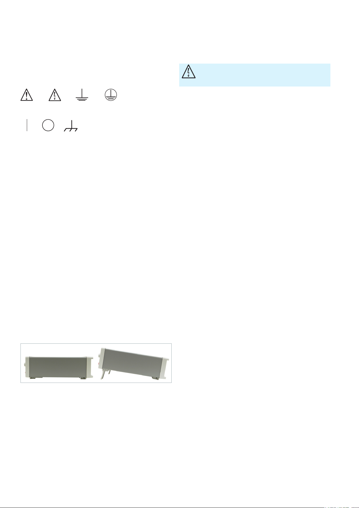
1.3 Instrument Setup
As shown in the picture below, the instrument may be
set up at a slight angle by using small extension legs that
unfold from its feet. Ensure that the extension legs are
completely unfolded to ensure secure footing.
Fig. 1.1: Operating positions.
Position the instrument so the power switch is not obstructed at any time.
1.4 Safety
This instrument is designed in accordance with EN
61010-1 (VDE 0411 Part 1), Safety Requirements for
Electrical Equipment for Measurement, Control and
Laboratory Use, and left the factory in perfect condition. It
thus also meets the requirements of European Standard
EN 61010-1 and the international standard IEC 61010-1. To
maintain this condition and ensure safe operation, the user
All exposed metal parts have been tested against the AC
power leads with a test voltage of 2200 VDC. The instru-
ment complies with overvoltage category CAT II (600V). To
ensure safe operation, the instrument may only be operated from a properly grounded power outlet. Plug in the
power cord before connecting any signal circuits. Never
use the product if the power cable is damaged. Check the
power cable on a regular basis to ensure that it is in proper
operating condition. Take appropriate safety measures and
carefully lay the power cable to ensure that the cable will
not be damaged and that no one can be hurt by, for example, tripping over the cable or suffering an electric shock.
Any time there is reason to believe that safe operation is
no longer possible, the instrument must be taken out of
service and secured against inadvertent use.
Safe operation is not possible:
❙ If the instrument shows visible damage
❙ If the instrument is no longer working
❙ Following long-term storage under unfavorable conditions
(e.g. outdoors or in damp rooms)
❙ After severe transport stress (e.g. in packaging that does
not meet the minimum conditions for shipping by post,
rail or truck)
Prior to switching on the product, always ensure that the
nominal voltage set on the product matches the nominal
voltage of the mains supply. If a different voltage is to be
set, the mains fuse of the product may have to be changed
accordingly.
1.5 Intended Use
This instrument is only intended to be used by persons
who are familiar with the risks associated with measuring
electrical quantities. The instrument may only be operated with a properly grounded power outlet. Never use a
“cheater plug” or other means to defeat or disconnect the
protective ground lead. The power plug must be connected before any signal circuits are connected. The product may be operated only under the operating conditions
and in the positions specied by the manufacturer, without
the product's ventilation being obstructed. If the manufac-
turer's specications are not observed, this can result in
electric shock, re and/or serious personal injury or death.
Applicable local or national safety regulations and rules for
the prevention of accidents must be observed in all work
performed.
4
4
Page 5
Important Information
Important Information
The instrument is intended for use in the following areas:
❙ Industrial
❙ Residential
❙ Business and commercial
❙ Small business
The measuring device is to be used only with authentic ROHDE &
SCHWARZ test accessories, signal cables and power cords. Never
use power cords with insufcient ratings. Before starting each
measurement, the signal cables should be checked for damage and
replaced if necessary. Damaged or worn components may damage
the equipment or cause injury.
The instrument may only be used indoors. Before each
measurement, check the instrument for proper operation
using a known signal source or sample.
To disconnect from the power supply, the rear uncooled IEC plug
must be removed.
1.6 Ambient Conditions
The permissible operating temperature is +5 °C to +40 °C
(connector contamination level 2). The maximum permissible relative humidity (non-condensing) is 80 %. During
storage or transport, the permissible temperature range
is –25 °C to +60 °C. If condensation has formed during
transport or storage, the equipment should be allowed to
acclimatize to ambient levels for about two hours before
use. The instrument is intended for use in clean, dry areas.
It may not be operated in dusty or damp conditions, an
explosion hazard area, or in the vicinity of aggressive
chemicals. The instrument can be positioned as needed,
but sufcient air circulation must always be ensured. For
prolonged operation, a horizontal or slightly angled operating position (extension legs) is preferable.
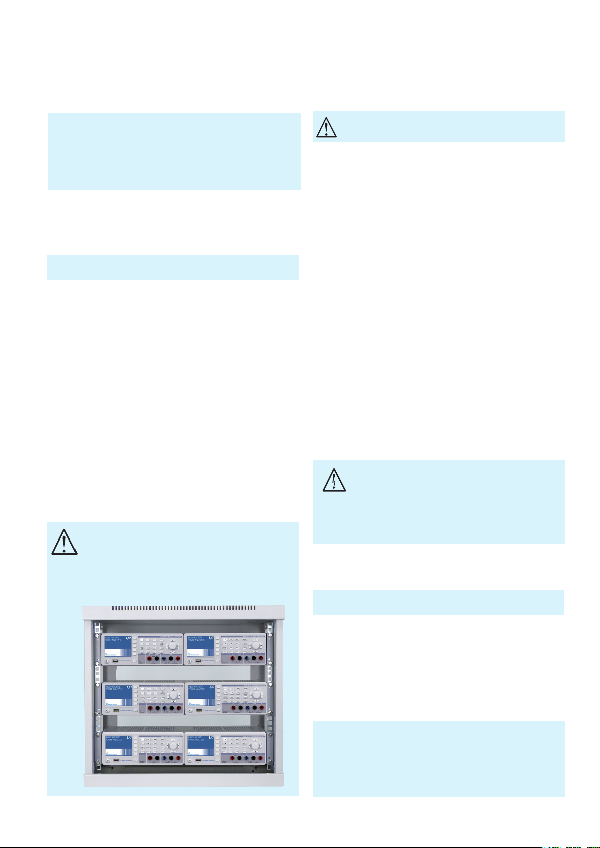
When installing one or more R&S®HMC8015 units in a 19inch rack, make sure that there is enough space around
its periphery to ensure sufcient cooling (see gure).
Recommended minimum clearance: 1 height unit (HU)
The instrument may be operated at an altitude of up to
2000 m. The specications and tolerances apply after
a warm-up time of at least 60 minutes, at an ambient
temperature of 23 °C (± 2 °C). All values stated without
tolerances are typical values for an average unit.
The ventilation openings must not be
covered!
1.7 Warranty and Repair
ROHDE & SCHWARZ equipment is subject to strict quality
control. Before leaving the production line, each device
is subjected to a 10-hour “burn-in test”. This is followed
by an extensive functional test and quality inspection, in
which all operating modes and compliance with speci-
cations are checked. These tests are carried out using
equipment that is calibrated traceable to national standards. The statutory warranty provisions of the country in
which the ROHDE & SCHWARZ product was purchased
are applicable. In the event of any complaints, please
contact the dealer from whom you purchased the ROHDE
& SCHWARZ product.
All adjustments, parts replacements, maintenance and
repairs must be carried out by authorized ROHDE &
SCHWARZ specialists. Only original parts may be used
for replacing safety-relevant parts (e.g. mains switches,
mains transformers, fuses). After each replacement of
safety-relevant parts, a safety check (visual inspection, PG
conductor test, insulation resistance test, leakage current
measurement, functional testing) must be performed. This
helps ensure the continued safety of the product.
The product may only be opened by authorized,
specially trained personnel. Before any work is
performed on the product or before the product is
opened, it must be disconnected from the supply
voltage. Otherwise, personnel will be exposed to the
risk of an electric shock.
1.8 Maintenance
The outside of the instrument should be cleaned regularly with a
soft, lint-free dust cloth.
The display may only be cleaned with water or a suitable glass cleaner (not with alcohol or solvents), followed
by wiping with a clean, dry, lint-free cloth. Never allow
cleaning liquid to enter into the equipment. Other cleaning
products may dissolve the labels or mar the plastic surface
and painted or varnished surfaces.
Before cleaning the instrument, make sure that it is turned off
and disconnected from any power supply (e.g. AC power grid or
battery).
No part of the equipment should be cleaned with chemical solvents such as alcohol, acetone or paint thinners!
5
5
Page 6
Important Information
Important Information
1.9 CAT II
This instrument is intended for measurements on circuits that are or are not connected directly to the normal
(low-voltage) AC power grid. The device complies with
measurement category CAT II; the input voltage must not
exceed 600 V
in a CAT II application.
RMS
The following information relates exclusively to user
safety. Other aspects, e.g. the maximum permissible
input voltage, are specied in the technical data sheets
and must also be observed. Indirect measurements on
the power grid may be performed by means of appropriate transducers (e.g. current probes) that meet or exceed
the requirements of the protection class applicable to the
measurement task. When measuring, the transducer’s
measurement category – as specied by the manufacturer
– must be observed.
Measurement categories
The measurement categories relate to transients superimposed on the AC line voltage. Transients are short, very
fast (steep) voltage and current changes that may occur
either periodically or non-periodically. The amplitude of
possible transients increases as the distance to the source
of the low-voltage network decreases.
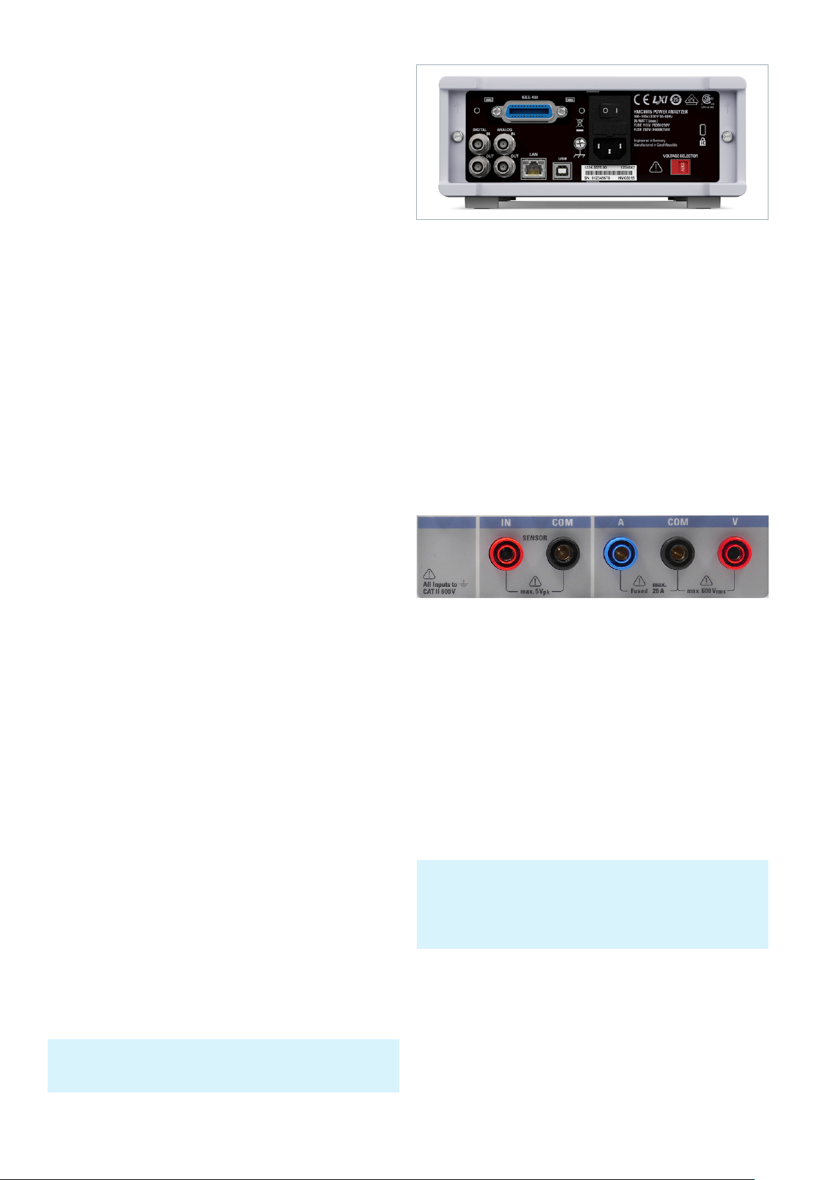
Fig. 1.2: Rear panel with supply voltage selector and connections.
The measuring circuit is equipped with a current overow
fuse against excess current that cannot be serviced or
replaced by the user.
1.11 Limit Values
The R&S HMC8015 is equipped with an overload protection circuit. The overload protection circuit is used to
prevent damage to the unit, and to protect against possible
electrical shock. The limit values of the unit must not be
exceeded. The front panel of the R&S HMC8015 species
the protection limit values in order to ensure safe operation of the unit. These protection limits must be strictly
observed:
❙ Measurement category IV: Measurements at the
source of the low-voltage network (e.g. on electricity
meters).
❙ Measurement category III: Measurements in a building
network (e.g. distribution panels, circuit breakers,
permanently installed electrical outlets, stationary
motors, etc.).
❙ Measurement category II: Measurements on circuits
directly connected to the low-voltage power grid (e.g.
household appliances, power tools, etc.)
❙ 0 (Devices with no measurement category rating): Other
circuits that are not directly connected to the power grid.
1.10 Supply Voltage
Before turning on this device, please check that the available supply voltage (115 V or 230 V ±10 %, 50 Hz to 60 Hz)
matches the specications on the supply voltage selector
switch of the device. If this is not the case, the supply volt-
age must be adjusted using the switch. The mains voltage
selector switch is located on the rear panel of the unit.
The unit has a main power fuse, which is located on
the rear panel of the unit for uncooled IEC connectors.
Depending on the supply voltage setting, a fuse of the correct type must be installed.
❙ At the 115 V setting: F630L250V
❙ At the 230 V setting: F400L250V
If the equipment must be left unattended for a long period of
time, it must be switched off at the power switch for safety
reasons.
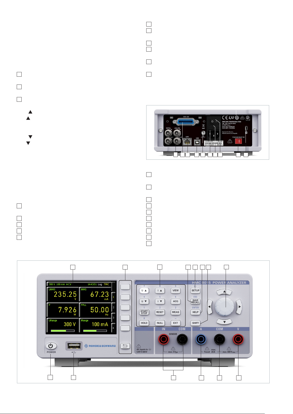
Fig. 1.3: Connections on the front panel.
Voltage input: 600 V
RMS
Current input: 20 A
Max. voltage
between COM and IN: 5 V
Peak
Connection to power supply:
115 V / 230 V, selectable with the voltage selector on
the rear panel of the unit
Frequency: 50 -60 Hz
Power consumption: 35 W maximum, 15 W typical
1.12 Batteries and Accumulators/Cells
If the information regarding batteries and accumulators/cells
is ignored or not sufciently observed, this may lead to explosion, re and serious personal injury or death. The handling of
batteries and accumulators based on alkaline electrolytes must
conform to EN 62133.
1. Cells must not be taken apart, opened or crushed.
2. Cells or batteries must not be exposed to heat or re.
Storage in direct sunlight must be avoided. Keep cells
and batteries clean and dry. Clean soiled connectors
using a dry, clean cloth.
6
6
Page 7

3. Cells or batteries must not be short-circuited. Cells or
batteries must not be stored loose in a box or drawer
where they can short-circuit each other, or where they
can be short-circuited by other conductive materials.
Cells and batteries must not be removed from their
original packaging until they are ready to be used.
4. Keep cells and batteries out of the reach of children. If
a cell or battery has been swallowed, seek immediate
medical care.
5. Cells and batteries must not be subjected to any mechanical impacts that are stronger than permitted.
6. If a cell develops a leak, the uid must not come into
contact with the skin or eyes. If contact occurs, wash
the affected area with plenty of water and seek medical
aid.
7. Cells or batteries that are not properly replaced or
charged pose a risk of explosion. To ensure that the
product remains safe to use, always replace cells or
batteries with the matching type.
Important Information
Important Information
8. Cells and batteries must be recycled and kept separate from regular household waste. Accumulators or
batteries that contain either lead, mercury or cadmium
are hazardous waste. Observe the national regulations
regarding waste disposal and recycling.
1.13 Product Disposal
Fig. 1.4: Product labeling in accordance
with EN 50419.
The German Electrical and Electronic Equipment Act (ElektroG) implements the following EC directives:
❙ 2002/96/EC (WEEE) for electrical and electronic
equipment waste and
❙ 2002/95/EC on the Restriction of Use of Hazardous
Substances in electrical and electronic equipment (RoHS
directive)
At the end of the lifecycle of this product, it may not be
disposed of with normal household waste. Moreover,
disposal via the municipal collection points for electrical
equipment waste is also not permissible. Rohde & Schwarz
GmbH & Co. KG fully assumes the manufacturer’s obligations to take back and dispose as set forth by the ElektroG,
to ensure environmentally sound disposal or recycling of
the materials used.
Please contact your local service representative in order to
dispose of the product.
7
7
Page 8
Instrument Controls and Indicators
Instrument Controls and Indicators
2 Instrument Con-
trols and Indicators
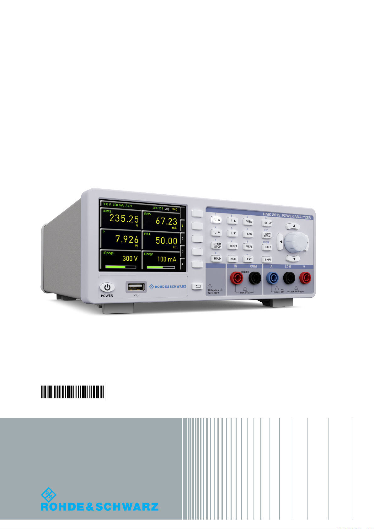
¸HMC8015 front panel
1
Display – 3.5" TFT color display with QVGA resolution
(320 pixels x 240 pixels)
2
Interactive softkeys – Direct access to all relevant func-
tions
3
Function Keys – Operates as a numeric keypad using
SHIFT function
U – Increases voltage range manually
I – Increases current range manually
VIEW – Switches between graphical and numeric dis-
play
U – Decreases voltage range manually
I – Decreases current range manually
ACQ – Data acquisition menu for recording data
START / STOP – Starts/stops the energy counter
RESET – Resets peak values / energy counter
MEAS – Logging function / energy counter / limit val-
ues
HOLD – Stops the update of measurement values
NULL – Sets the current display values as zero refer-
ence values
EXT – Sensor menu and additional functions
4
SAVE/RECALL – Saves and recalls/uploads device set-
tings
5
SETUP – Gives access to general device settings
6
HELP – Integrated help screen
7
SHIFT – Activates the numeric keypad
8
Universal rotary control knob with arrow keys – Sets
the parameters cells (editing keys)
V jack – Input for voltage measurement
9
COM jack – Shared measuring input for voltage and
10
current measurement
A jack – Input for current measurement
11
IN/COM jacks – Sensor input for external shunts or cur-
12
rent probes
USB port – USB host port for USB ash drives when
13
saving parameters
POWER – ON/OFF for standby mode
14
¸HMC8015 rear panel
15
Fig. 2.2: ¸HMC8015 rear panel.
15
Digital / Analog IN/OUT – Digital / analog inputs and
19181716
20 21 2422
23
outputs for Pass/Fail sorting and limit values
16
IEEE-488 (GPIB) interface (optional) – Installation avail-
able at factory only
17
Ethernet (LAN) interface
18
USB interface
19
Ground terminal
20
Uncooled IEC plug
21
Fuse
22
Power switch
Supply voltage selector switch (115V or 230V)
23
24
Kensington lock
1
14
Fig. 2.1: ¸HMC8015 front panel.
8
8
13
2
3
12
4
5 6 7
11
8
10
9
Page 9
3 Options/Upgrade
Vouchers
The R&S®HMC8015 has available options that increase the
application scope of the instrument. Options and upgrade
vouchers can be combined. The following options (or upgrade vouchers) are available for the R&S®HMC8015 power
analyzer:
Options/Upgrade Vouchers
Options/Upgrade Vouchers
Description ¸HMC8 015
Advanced Analysis ¸HOC151 ¸HVC151
Advanced IO ¸HOC152 ¸HVC152
Table 3.1: Overview of ¸HMC8015 options/upgrade vouchers
options
1)
¸HMC8 015
upgrade vouchers
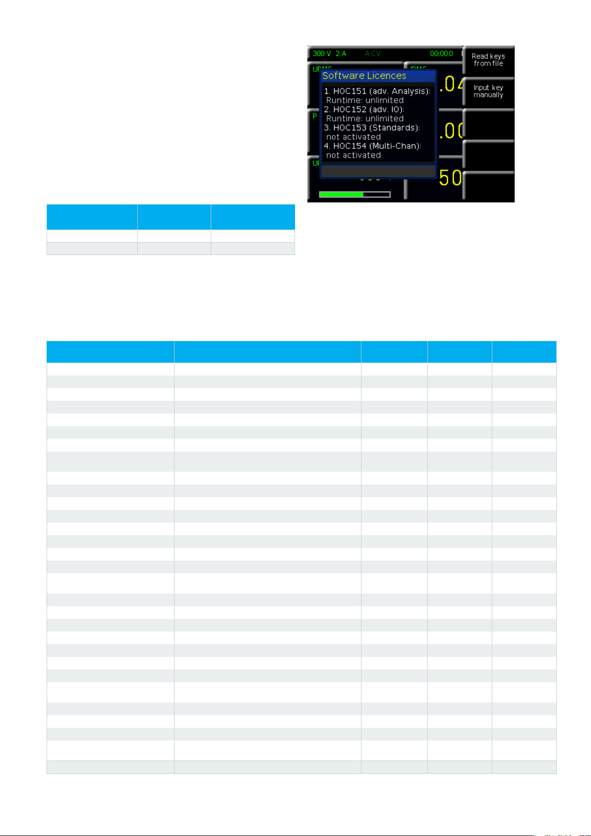
Fig. 3.1: Upgrade menu.
2)
The R&S®HOC151 Advanced Analysis option or
R&S®HOC152 Advanced IO function can both be purchased from the factory with an R&S®HMC8015. In contrast, the R&S®HV151 Advanced Analysis upgrade voucher
1) Only when ordered in combination with a ¸HMC8015 base unit
2) Subsequent activation of ¸HMC8015 options via upgrade voucher
Function Description
P Active power (W) ●
S Apparent power (VA) ●
Q Reactive power (var) ●
PF Power factor lambda (λ) ●
PHI Phase shift (φ) ●
FU Frequency value for the voltage (Hz) ●
FI Frequency value for the current (Hz) ●
FPLL
URMS True root mean square (RMS) voltage (U
UAVG Average voltage ●
IRMS True root mean square (RMS) current (I
IAVG Average current ●
UTHD Total harmonic distortion U ●
ITHD Total harmonic distortion I ●
WHM, WHP, WH, AHM, AHP, AH Energy counter (integrator values) ●
Logging Data recording (comma-separated values CSV) ●
USB, Ethernet
(GPIB optional – HMC8015- G)
UPPeak Maximum voltage (U
UMPeak Minimum voltage (U
IPPeak Maximum current (I
IMPeak Minimum current (I
PPPeak Maximum power (P
PMPeak Minimum power (P
HARMONICS mode Bar graph of 50 harmonics ●
WAVEFORM mode
TRENDCHART mode Current or voltage displayed as signal prole ●
INRUSH mode Triggered display of a signal prole (single shot) ●
Sensor input Input jack for current probe / external shunt ●
DIN / AIN
Limit value / PASS-FAIL Displays limit values ●
Table 3.2: Feature overview: options/upgrade vouchers
Frequency and phase locked loop recording frequency (Hz)
Remote interfaces ●
) ●
+pk
) ●
–pk
) ●
+pk
) ●
–pk
) ●
+pk
) ●
–pk
Displays the waveform (for one cycle of voltage, current or power data)
Digital / analog inputs and outputs (Bayonet Neill –
Concelman BNC)
or R&S®HV152 Advanced IO upgrade voucher enable a
subsequent upgrade via a license key. The installed options or upgrade vouchers can be looked up under “Device
R&S®HMC8015
) ●
RMS
) ●
RMS
base unit
●
¸HOC151
¸HVC151
●
¸HOC152
¸HVC152
●
9
9
Page 10
Options/Upgrade Vouchers
Options/Upgrade Vouchers
Information” in the SETUP menu. Table 3.2 shows an overview of the most important optional features. For com-
plete specications, please visit the ROHDE & SCHWARZ
homepage.
To generate a license key, go to http://voucherrs.hameg.
com and enter the voucher code. The license key (SERI-
ALNUMBER.hlk) is an ASCII le and can be opened using
a le editor. The key is listed in the le in plain text. Enable
the option in the instrument by either reading the key in
automatically or entering it manually. The fastest and easiest method is to read the key in automatically from a USB
ash drive. To do this, save the license le to a USB ash
drive and then insert the ash drive into the USB port on
the instrument front panel. Press the SETUP button and
then softkey LICENSE to open the menu for reading in
options and upgrade vouchers. Press softkey READ KEYS
FROM FILE to open the File Manager. Use the rotary con-
trol knob to select the license le, then press softkey LOAD
to load the key. The license key is loaded and the option is
available after the instrument has been restarted.
Alternatively, the license key can be entered manually. To
do this, press softkey INPUT KEY MANUALLY. This opens
an input window where the license key can be typed in
manually. Once the key has been entered, conrm by
pressing softkey ACCEPT. Restart the instrument to enable
the option.
4 Connecting a
Device under Test
4.1 Connecting a Device under Test via Adapter
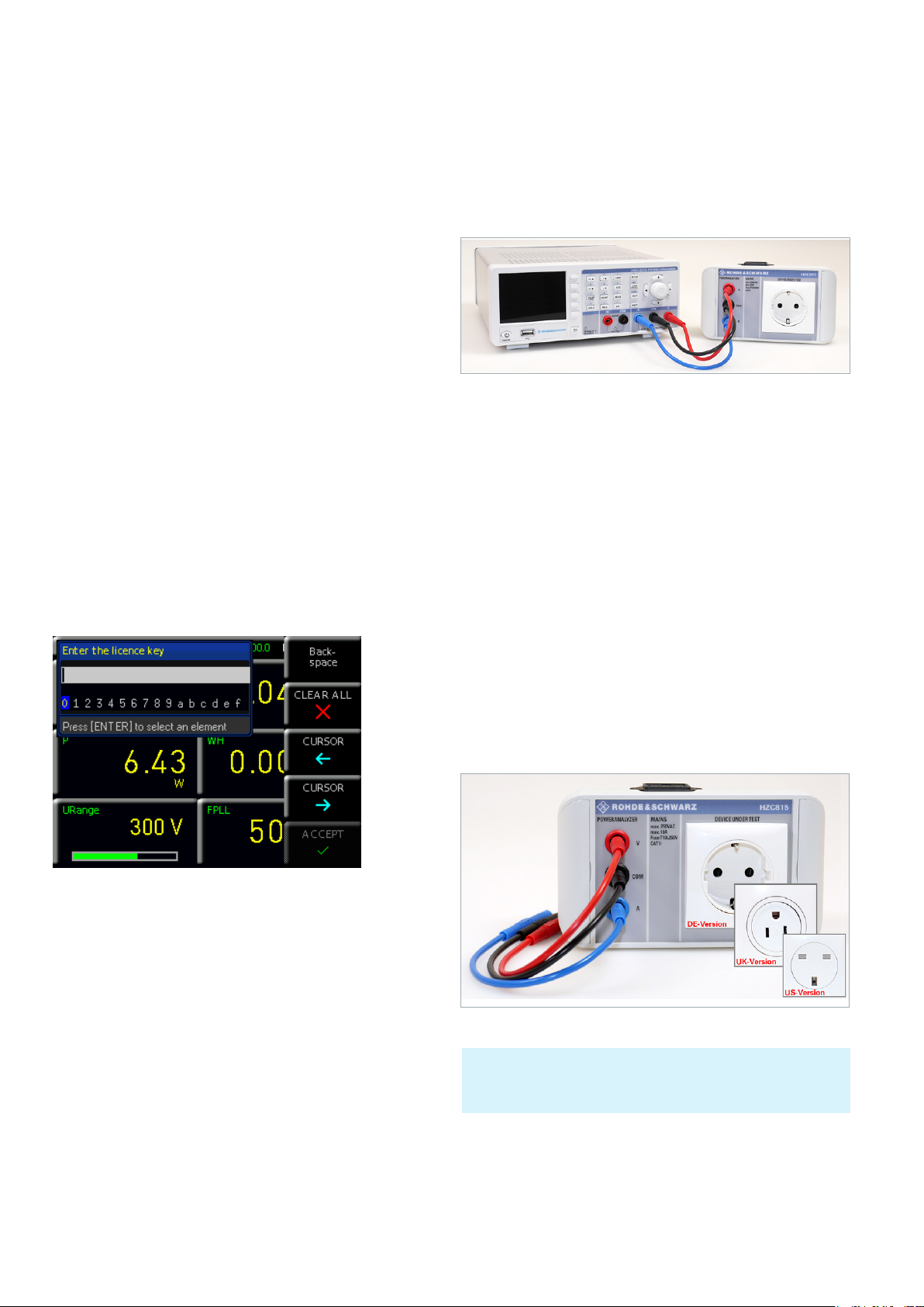
Fig. 4.1: Connecting HZC815 DE version to ¸HMC8015.
A device under test (DUT) can easily and securely be
connected to the ¸HMC8015 using the optional
HZC815 socket adapter. In this case, the cables enclosed
with the HZC815 (length = 25 cm) are connected to the
¸HMC8015 socket on the front panel. The connection
of the socket adapter to the ¸HMC8015 front panel is
determined by the color of the HZC815 accessory cables.
The cables on the socket adapter represent an extension
of contacts for a standard AC outlet with grounded safety
sockets and are used for measuring a DUT. Power is supplied to the HZC815 socket adapter through the uncooled
IEC plug on the top of the adapter and a power cord.
Fig. 3.2: Manually entering the license key.
There are 3 different types of HZC815 available ex factory:
❙ HZC815-DE: DE version; EU socket adapter (230V)
❙ HZC815-UK: UK version; UK socket adapter (230V)
❙ HZC815-US: US version; US socket adapter (115V)
Fig. 4.2: HZC815 DE, UK and US version plug adapters.
The HZC815 standard AC grounded safety outlet system is
only approved for a 10 A continuous load. A load of 20 A would
destroy the adapter.
10
10
On the sides of the HZC815 adapter, special faceplates
hide mounting screws. The socket adapter can be permanently mounted with these mounting screws if so desired.
Page 11
4.2.1 Internal Jack Wiring
Options/Upgrade Vouchers
Options/Upgrade Vouchers
Fig. 4.3: HZC815 DE version plug adapter with mounting screws.
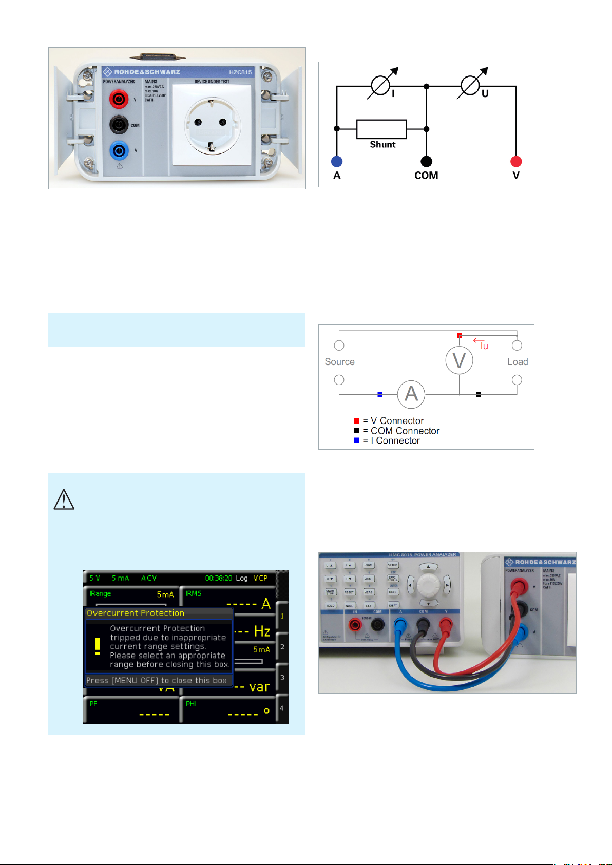
4.2 Connecting a Device under Test Directly
The ¸HMC8015 can measure voltages up to 600 V
and currents up to 20 A
. In these cases, a device under
RMS
RMS
test (DUT) can be directly connected to the power analyzer
using the 4 mm safety jacks on the front panel.
Before the start of each measurement, the signal cables to be used
must be checked for damage and wear.
Voltages are measured using the red V jack; currents are
measured using the blue A jack. The black COM jack acts
here as the shared measuring input for voltage and current
measurement.
If the maximum values for current and voltage are exceeded, the ¸HMC8015 power analyzer is automatically switched off.
If the safety warning “Overcurrent Protection” appears
on the screen, then more than 2 A were supplied in the
low current range. The unit switches itself off in order
to protect the internal shunt. In this case, switch to the
automatic range selection (AUTO) or a higher range (>
500 mA) manually.
Fig. 4.4: Internal wiring of A, V and COM jacks.
The 4 mm A, V and COM safety jacks on the front panel
are not electrically isolated and separate from each other,
and therefore offer several methods for measuring a DUT:
❙ Voltage-based measurement
❙ Current-based measurement
❙ Measurements via external shunt / current probe
4.2.2 Voltage-Based Measurement
Fig. 4.5: Voltage-based measurement.
Voltage-based measurement is typically used with high
currents, since the voltage drop at the shunt increases as
the current increases. The voltage U is correctly measured
at the load.
Fig. 4.6: Voltage-based measurement, wiring example.
4.2.3 Current-Based Measurement
Current-based measurement is preferred with low currents
and high voltages, because it prevents current owing
through the voltage measuring jack from going through
the shunt, which would falsify the reading. With this measurement type, the current reading must be inverted (IN-
11
11
Page 12
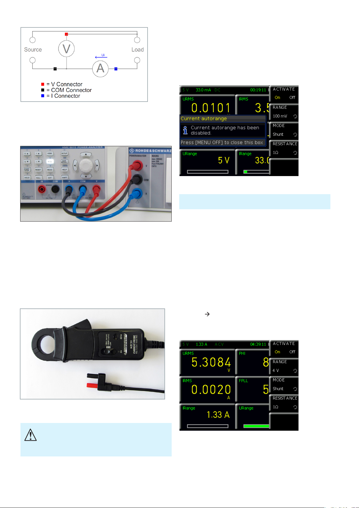
Options/Upgrade Vouchers
Options/Upgrade Vouchers
Fig. 4.7: Current-based measurement.
VERT) using the ACQ menu and softkey menu CURRENT.
In addition, the I and COM cables need to be reversed (see
Fig. 4.8).
4.3 Sensor Menu
The Sensor conguration menu is opened via the EXT
menu and the softkey menu SENSOR. Press softkey
ACTIVATE to activate (ON) or deactivate (OFF) the sensor
measurement. When the sensor measurement is activated
(ON), the automatic current measurement (AUTO) is deactivated (if it was activated previously).
Fig. 4.10: Sensor menu.
Fig. 4.8: Current-based measurement, wiring example.
4.2.4 Measurements with an External Shunt or
Clamp-on Current Probe
The 4 mm safety jacks IN and COM are used for making
measurements with an external shunt or clamp-on current
probe. Safety plugs connect the shunt or clamp-on probe
directly to the jacks. Accessories such as HZC50 or HZC51
can be used for the clamp-on probe.
The softkey ACTIVATE activates the sensor inputs IN and COM
on the instrument front panel (hardware switch).
Use the softkey RANGE and the rotary control knob to
select the maximum measuring range for the measured
voltage. The available settings are 100mV, 1V and 4V. As
a rule, the 100mV range is appropriate for measurements
on shunts, while 1V and 4V are used for measurements
with a current probe. This setting is referenced to the peak
value.
Example for shunt:
Set RESISTANCE to 1Ω.
Set RANGE to 4V.
Convert as follows:
1V = 1A 4V divided by CF3 = 1.33A.
Use the cell conguration to display this power range as
IRANGE on the screen.
Fig. 4.9: HZC51 Clamp-on current probe.
The connection of a clamp-on probe through a BNC adapter
is not allowed, since depending on the polarity of the volt-
age, the measuring voltage may be present across the BNC
plug coupling.
12
12
Fig. 4.11: Example of a sensor.
Use softkey MODE and the rotary control knob to select
the sensor mode. The available modes are SHUNT (to
connect an external shunt) and CLAMP (to connect a
current probe, e.g. HZC50 / HZC51). The Sensor menu
Page 13

changes dynamically to match the selected sensor mode.
In sensor mode SHUNT, softkey RESISTANCE is used to
enter the value of the externally connected shunt in ohms.
Select the value using the rotary control knob or press the
SHIFT button to input the value numerically. If you entered
the value numerically, press the appropriate unit on the
softkey menu to conrm the value. Once the shunt value
is entered, all measured values (current, power and values
derived from these) can be calculated correctly and displayed. Manual calculations are no longer necessary. The
data from the external shunt is converted to the correct
measured values internally.
Setting Parameters
Setting Parameters
5 Setting Parameters
5.1 Using the Instrument for the First Time
Pay particular attention to the safety instructions indicated
above when using the instrument for the rst time!
After connecting the uncooled IEC power cable and
operating the power switch on the rear panel, the unit can
be switched on by pressing the POWER button on the
front panel. A help screen appears automatically. If you do
not want to see the help screen, it can be hidden with the
HIDE function. With the HIDE FOREVER softkey, the help
screen feature will be disabled and no longer automatically
displayed after restarting. After doing this, the help function can only be opened using the HELP button.
Whenever the power analyzer is switched on, it is in the
same mode as when it was last shut down. All device
settings are stored in nonvolatile memory (NVM) and
retrieved when restarting.
Fig. 4.12: Sensor mode.
In sensor mode CLAMP, softkey RATIO and the rotary con-
trol knob are used to dene a conversion factor. This factor
denes how many millivolts the sensor transmits when
a current of 1A is applied. Once the factor is entered, all
measured values (current, power and values derived from
these) can be calculated correctly and displayed. Manual
calculations are no longer necessary. Available factors are
1mV/A, 10mV/A and a user-dened value (USER). The
conversion factors 1mV/A and 10mV/A are appropriate for
the current probes HZO50 and HZO51, for example. If you
are using a current probe from a different manufacturer,
use the rotary control knob to select the factor or use the
SHIFT button to input the factor numerically.
5.2 Screen Display Description
1 2 3 4 6
7
8
9
1
Voltage measuring range
2
Current measuring range
3
Operating mode
4
Time displayed as function of the operating mode
5
Logging enabled (yellow) / disabled (white)
6
Type of interface: GPIB / TMC / VCP / LAN
7
Cell function
8
Measuring parameter cell with reading
9
Measuring range and modulation shown as bar
5
graphs (URange / IRange function)
10
Softkey menu 1 to 4 used to congure the meas-
uring parameter cell / display toggles between six and
10 measurement values
10
Fig. 5.1: Screen display description.
13
13
Page 14

Setting Parameters
Setting Parameters
Fig. 5.2: Help function.
5.3 Multifunction Softkeys
The menu eld that appears on the screen can be manipulated using the softkeys on the right side of the screen.
After a menu is activated by using the function keys on the
front panel, control and conguration of the menu functions is done by using the softkeys. If a device function is
not available within a specic setting (e.g. if an option or
upgrade voucher is not installed), then the corresponding
softkey is disabled and the caption is grayed out. Close a
menu or jump back one menu level using the softkey
at the very bottom. In addition, the Quick Menu and the
softkeys 1 to 4 can be used to congure the display of the
measuring parameter cells. If the softkey of the already
active conguration page is pressed again, it is possible
to toggle between a display of six and 10 parameter cells.
Each cell can be fully customized. Up to four conguration
menus are available.
5.4 ConguringtheOperatingModefromaListof
Measuring Parameter Options (“Cells”)
The individual functions and operating modes of the
power meter can be selected using the buttons on the
front panel. To select a device function, the corresponding
function key is pressed. The white LED inside the key is lit
as an indication that the function is active. The editing of
a cell is activated by pressing on the rotary control knob
or one of the arrow keys. The rst cell on the top left is
highlighted in blue. The relevant parameter cell can then
be selected using the rotary control knob or the arrow
keys. Once a parameter cell is selected, the parameter list
can be opened by pressing the rotary control knob again.
When a measuring parameter has been selected, it can be
conrmed by pressing the rotary control knob, or after 20
seconds without input, the unit will automatically return to
the previous screen (see Section 9.3.5 Key Fallback Time).
5.5 Readout Display
The R&S®HMC8015 power analyzer has a TFT color display. The screen is divided into two sections. The rst section is the status bar, in which the currently active modules
and interface information are displayed. Table 3.2 presents
a general overview of the power meter’s split screen with
all possible function displays and their descriptions.
Fig. 5.4: Readout display with six active cells.
The eld of cells is variable and dependent on the operating mode. In NUMERIC mode (set by default), typical
numeric measurement values, such as power, voltage, current etc., are displayed. By contrast, in HARMONICS mode
(HVC151 option required), the harmonics of the signals are
displayed as bar graphs. Each mode has its own menu
structures, which can be congured by using the softkeys.
By default, the display consists of either six or 10 cells with
four different conguration pages.
Fig. 5.3: Selecting the measurement function.
14
14
Fig. 5.5: Readout display with 10 active cells.
With the HOLD function, the current measurement results
are paused and shown on the display. Therefore when
the HOLD button is pressed (button is lit), the particular
measurement values are frozen on the display. The data
recording is then running in the background. If the HOLD
button is pressed again (LED turned off), the function is
deactivated.
Page 15

Setting Parameters
Setting Parameters
Using the NULL button, the current readings are taken as
reference values and any deviation from them is shown
on the display. If the NULL function is activated, the LED
inside the button is lit. To deactivate the NULL function,
press the button again (LED turned off).
If the device shows only dashes “---” on the display, the
¸HMC8015 could not determine a valid frequency. This can
occur, for example, when the AC function was selected and the
signal amplitude is too small or when the measuring range has
been set too high.
5.6 Selecting the Measuring Range
The individual functions and operating modes of the
R&S®HMC8015 unit can be selected using the buttons on
the front panel. Basic functions, such as voltage or current
measuring range, can be selected through the corresponding function keys. Using the U, I, U and I keys, the
measuring range can be increased or decreased manually.
U or I switches to the next higher, U or I to the
next lower voltage or current measuring range.
In automatic range selection mode, this leads to a switch
to the next higher range if the signal readings exceed
120% of the current measuring range. The unit switches
to the next lower range if 0.6s have elapsed since the last
range change and the RMS reading is within 95% of the
next smaller measuring range.
Moreover, by using the ACQ menu, the automatic measuring range selection (AUTORANGE) for current or voltage
can be activated (ON) or deactivated (OFF) in the VOLTAGE
or CURRENT softkey menu. The manual range selection is
automatically disabled when using AUTORANGE.
In the case of manual range selection, if the applied value is too
large, the display will show the message “OL” (overload).
Fig. 5.6: Example of measuring range display.
Push long the U , I , U and I keys to activate the automatic
measurement range mode.
Using the URANGE or IRANGE measurement parameters,
the modulation of the selected measuring range can be
graphically displayed (bar graph) on the screen. If the measuring range is manually adjusted with the U, I, U
and I keys, the bar graph is changed accordingly. A red
measuring range bar indicates that the measuring range of
the incoming signal is too small.
Fig. 5.7: Selecting the measurement function.
If, at crest factor 3, the instrument is in a current measuring
range less than 200 mA and automatic current range selection
is activated, then the data acquisition hardware automatically
switches to the highest current measuring range for any large
overcurrent (e.g. 2 A).
15
15
Page 16

Instrument Functions
Instrument Functions
6 Instrument
Functions
6.1 Measurement Parameters
Fig. 6.1: R&S®HMC8015 readout display.
In NUMERIC mode, the instrument screen provides an
overview of the measurement values. The numeric values
displayed on the instrument screen are instantaneous val-
Fig. 6.2: Option / upgrade voucher info box.
ues that are constantly updated. If an instrument function
is grayed out in the menu, the purchase of an option/upgrade voucher is required in order to unlock this feature. If
the softkey of the grayed-out function is pressed, then an
info box appears on the screen with the required option/
upgrade voucher (see Chapter 3).
6.2 Display Modes (VIEW Menu)
R&S®HMC8015 base unit
P Active power (W)
S Apparent power (VA)
Q Reactive power (var)
PF Power factor lambda (λ)
PHI Phase shift (φ)
FU Frequency value for the voltage (Hz)
FI Frequency value for the current (Hz)
FPLL Frequency and phase locked loop recording frequency (Hz)
URMS True root mean square (RMS) voltage (U
UAVG Average voltage
IRMS True root mean square (RMS) current (I
IAVG Average current
UTHD Total harmonic distortion U
ITHD Total harmonic distortion I
Wh+ Positive watt hours
Wh– Negative watt hours
Wh Sum of positive and negative watt hours
Ah+ Positive ampere hours
Ah– Negative ampere hours
Ah Sum of positive and negative ampere hours
R&S®HMC8015 base unit + HOC151 option /HVC151 voucher
UPPeak Maximum voltage (U
UMPeak Minimum voltage (U
IPPeak Maximum current (I
IMPeak Minimum current (I
PPPeak Maximum power (P
PMPeak Minimum power (P
R&S®HMC8015 base unit + HOC152 option /HVC152 voucher
DIN Digital input value (digital IN)
AIN Analog input value (analog IN)
Limit N Limit display
Table 6.1: Overview of measurement functions
–pk
–pk
+pk
+pk
–pk
+pk
)
)
)
)
)
)
RMS
RMS
)
)
Fig. 6.3: VIEW menu.
The R&S®HMC8015 power analyzer includes ve different display modes for the display of measurement results;
these can be enabled by activating options/upgrade
vouchers. The display modes can be selected using the
VIEW menu. The following display modes are available:
❙ Numeric mode: (default display)
Numeric display, toggles between six and ten
measurement parameters presented as cells with four
different conguration pages; this provides a quick
overview of the individual, congurable measurement
value cells.
❙ Harmonics mode:
Bar graph of the rst 50 harmonics; this represents the
density of voltage / current as a percentage, absolute
value or as a list. HARMONICS mode is only available in
conjunction with the HOC151 option or the HVC151
upgrade voucher.
❙ Waveform mode:
Displays the waveform (for one cycle of voltage, current
or power data). WAVEFORM mode is only available in
conjunction with the HOC151 option or the HVC151
upgrade voucher.
16
16
Page 17

Instrument Functions
Instrument Functions
❙ Trendchart mode:
Current or voltage displayed as a signal prole (similar to
the roll mode in an oscilloscope). TRENDCHART mode is
only available in conjunction with the HOC151 option or
the HVC151 upgrade voucher.
❙ Inrush mode:
Triggered display of a signal prole (single shot); INRUSH
mode is only available in conjunction with the HOC151
option or the HVC151 upgrade voucher.
6.2.1 Harmonics Mode
Fig. 6.4: Logarithmic readout display in Harmonics mode.
FFT is used to calculate the RMS value and phase angle of
the harmonics. This includes a calculation of the rst 50
harmonics (100kHz max.). Instead of the total RMS value,
the display shows the voltage level or the current level of
the individual harmonics selected using the cursor. The
cursor, which appears in the form of a small triangle under
the indicator bar, is moved using the rotary control knob.
The voltage levels (softkey SOURCE U – Quick Menu U)
are displayed as blue bars and the current levels (softkey
SOURCE I – Quick Menu I) as blue bars. Using SCALING
(Quick Menu A or %), it is possible to select a scaling factor for the signal in the Y-axis with reference to the fundamental (ABS or %). The measurement diagram is displayed
logarithmically on the screen so that even the smallest
signal details are visible.
key NUMBER (Quick Menu #) and the rotary control knob
can be used to display the number of harmonics included
in the FFT calculation. The softkey SUBSET (Quick Menu E
or O) can be used to dene what harmonics are to be used
in the calculation (EVEN, ODD or all). The voltage U or
current I or both can be selected as the source for the FFT
calculation (softkey SOURCE).
The FFT is calculated continuously. Settings made using softkeys
affect only the display of values on the screen.
Pressing the bottommost softkey closes the HARMONICS menu and opens a Quick Menu while the mode
remains active. This permits convenient control of the
harmonics settings via the Quick Menu. Pressing the VIEW
button and then selecting display mode NUMERIC closes
Harmonics mode and returns to the default display mode.
6.2.2 Waveform Mode
The WAVEFORM display mode can be used to display
the voltage, current and power simultaneously as a trace
on the screen (hardware-based triggering). Exactly one
signal period is displayed in the measurement diagram and
automatically scaled to the measuring range nal value.
Softkeys U, I and P are used to display or hide the traces
for voltage (blue), current (red) and power (green). In addition, softkey R (Readouts) can be used to display statistical
values, including U
RMS
, I
, FPLL (= trigger frequency)
RMS
and P (power).
Fig. 6.5: Tabular display in Harmonics mode.
The softkey VIEW SELECT (Quick Menu B or T) can be
used to switch the harmonics display between a bar graph
(BAR) or a table (TAB). Unlike the bar graph, the tabular
display includes both the magnitude and phase. The soft-
Fig. 6.6: Quick Menu in Waveform mode.
Pressing the bottommost softkey closes the WAVEFORM menu and opens a Quick Menu while the mode
remains active. This permits convenient control of the settings via the Quick Menu. Pressing the VIEW button and
then selecting display mode NUMERIC closes Waveform
mode and returns to the default display mode.
6.2.3 Trendchart Mode
TRENDCHART display mode is used to view two selected
values over time. Softkeys SRC 1 (Source 1 – Quick Menu
1) and SRC 2 (Source 2 – Quick Menu 2) are used to select
the values (sources). The following measurement functions
are available as sources:
17
17
Page 18

Instrument Functions
Instrument Functions
Fig. 6.7: Trendchart mode. Fig. 6.8: Inrush mode.
Acquisition of the trend is restarted any time the measurement function is changed. The trace scaling is set
automatically on the screen and cannot be changed. The
softkey TIME BASE can be used to select the temporal
resolution per scale division. The available values are 1s/
Div, 10s/Div, 1m/Div or 10m/Div. The existing trace data
is deleted any time the temporal resolution is changed.
The softkey CLEAR deletes the trace data from the screen
and starts a new acquisition. VISIBLE is used to activate
Source 1 and Source 2 (yellow) or to deactivate them
(white).
Function Description
P Active power (W)
S Apparent power (VA)
Q Reactive power (var)
PF Power factor lambda (λ)
PHI Phase shift (φ)
FU Frequency value for the voltage (Hz)
FI Frequency value for the current (Hz)
FPLL
URMS True root mean square (RMS) voltage (U
UAVG Average voltage
IRMS True root mean square (RMS) current (I
IAVG Average current
UTHD Total harmonic distortion U
ITHD Total harmonic distortion I
DIN Digital input value (digital IN)
AIN Analog input value (analog IN)
Table 6.2: Overview of SOURCE measurement functions in Trendchart mode
Frequency and phase locked loop recording frequency (Hz)
)
RMS
)
RMS
Pressing the bottommost softkey closes the TRENDCHART menu and opens a Quick Menu while the mode
remains active. This permits convenient control of the settings via the Quick Menu. Pressing the VIEW button and
then selecting display mode NUMERIC closes Trendchart
mode and returns to the default display mode.
6.2.4 Inrush Mode
INRUSH display mode uses an internal hardware buffer to
trigger acquisition of a rare event and to output it to the
display (similar to the single shot function found on oscilloscopes). This might be used to acquire inrush currents
on loads, for example. After an event occurs, the current
and voltage trends are acquired. The trend display starts at
the right-hand side of the screen. The softkeys VOLTAGE
(Quick Menu U) and CURRENT (Quick Menu I) are used to
activate (ON) and deactivate (OFF) the voltage and current
traces, respectively. Under SETTINGS, the trigger is set
to one of these two values, or it can be selected manually. A threshold (softkey LEVEL) can also be set, as well
as the offset between the rising and falling edges (softkey
SLOPE). At the full sampling rate, the acquisition runs for
16ms (softkey ACQ. TIME). The sampling rate can also be
varied to permit acquisition of signal sequences of over a
minute (see Table 6.3).
Sampling rate Acquisition time
500.00 ksample 16ms
250.00 ksample 32ms
125.00 ksample 65ms
62.50 ksample 130ms
31.25 ksample 260ms
15.63 ksample 520ms
7.81 ksample 1s
3.91 ksample 2s
1.95 ksample 4 s
976.56 sample 8s
488.28 sample 16s
244.14 sample 33s
122.07 sample 67s
Table 6.3: Overview of sampling rates
The trace display does not update dynamically. Instead, it
must be updated manually by pressing softkey ACTIVATE
(ON) (Quick Menu A). The trace is updated each time the
button is pressed (single shot). The Inrush display cannot
be zoomed. A maximum of 8000 measurement values
each for current and voltage can be acquired.
Pressing the bottommost softkey closes the INRUSH
menu and opens a Quick Menu while the mode remains
active. This permits convenient control of the settings
via the Quick Menu. Pressing the VIEW button and then
selecting display mode NUMERIC closes Inrush mode and
returns to the default display mode.
18
18
Page 19

Instrument Functions
Instrument Functions
6.3 Crest Factor
The crest factor (also known as peak factor) describes the
factor by which a signal’s amplitude (peak value) is greater
than the rms-calculated effective value. This is important
for the measurement of pulse-shaped sizes. For pure si-
nusoidal wave types, the following ratio applies: √2=1.414.
The accuracy of the calculated effective value remains
the same as long as the peak value stays within the peak
range. A crest factor of 1.8 or higher indicates a strong
distortion from the waveform. To evaluate the waveform
distortion of non-linear electric loads, the Waveform or
TRENDCHART mode can be used.
Example:
If a battery is charged with 4AH and discharged with
3AH, the display will show AHP = 4, AH– = –3 and the
total AH = 1 (i.e. 4 + (–3) = 1).
The Integrator menu can be opened by pressing the softkey INTEGRATOR in the MEAS menu. The relevant integrator mode is then selected using the softkey MODE and the
rotary control knob.
6.4.1 Manual Integrator Mode (Default)
Fig. 6.9: Sample conguration for crest factor 6.
From the ACQ menu, the crest factor can be varied between 3 and 6 by using the softkey CREST FACT in the
VOLTAGE or the CURRENT softkey menu. When changing
the crest factor, the measuring range is adjusted automatically. A crest factor of 5 or higher is used e.g. for sinusoidal
waveforms with spikes (see example in Fig. 6.4) and is
also required for standby measurements according to IEC
62018.
6.4 Energy Counter (Integrator Values)
The power analyzer makes it possible to display integrator values (WHP, WHM, AHP, AHM) on the screen. These
values are also activated via the measuring parameter cell.
In this way, the energy use of electronic devices under test
(DUT) can be recorded where power consumption is not
constant. WHP / AHP represent the power / current in the
positive direction and WHM / AHM in the negative direction. WH / AH correspond to the sum of the watt-hour/
ampere-hour positive and negative portions, respectively.
Fig. 6.11: MANUAL integrator menu.
The manual integrator mode is pre-selected by default.
Using the START softkey, or directly using the START/
STOP button on the front panel of the instrument, the
energy counter can be started as soon as it has been
activated (ON) using the ACTIVATE softkey. Pressing either
the softkey START or the START/STOP button on the front
panel once more will stop the energy counter. The RESET
softkey or the RESET button on the front panel will reset
the integrator values.
6.4.2 Span Integrator Mode
A start time (START TIME) and an integration time span
(DURATION) can be set using the SPAN integrator mode.
Once the energy counter has been activated (ON) via the
ACTIVATE softkey, the counter will automatically start at
the preset start time and then automatically stop after the
integration time span (DURATION) has elapsed. The time
span for the integration can be set using the rotary control
knob or, by using the SET TO CURR. softkey, the current
system time can be applied and adjusted accordingly.
Fig. 6.10: Readout display with integrator output values. Fig. 6.12: Span integration mode selection menu.
19
19
Page 20

Instrument Functions
Instrument Functions
Initiating the start separately by using the START/STOP
button on the front panel is not required. The RESET
button on the front panel will reset the integrator values.
The maximum duration for running the energy counter is 96
hours (DURATION).
Fig. 6.13: Setting the integration duration.
Fig. 6.14: Inversion.
blue A jack. In order to record and display the current correctly with this type of wiring, the current direction must
be inverted in the ACQ menu using the CURRENT softkey
menu and the INVERT softkey. When the INVERT function is activated, it is displayed as a green box around the
measuring range displayed in the status bar.
6.4.3 Duration Integrator Mode
The DURATION integrator mode denes how long the
energy counter is active. Using the START softkey, or
directly using the START/STOP button on the front panel of
the instrument, the energy counter can be started as soon
as it has been activated (ON) using the ACTIVATE softkey.
After the integration time (DURATION) has elapsed, the
energy counter is automatically stopped. The time display
in the status bar is replaced with the integration time. The
time span for the integration can be set using the rotary
control knob or, by using the SET TO CURR. softkey, the
current system time can be applied and adjusted accordingly. If the integration time is expired, a new integrator
measurement can only be started via START button, if the
integrator values were reset with RESET softkey.
6.4.4 External Integrator Mode
(only with the HOC152 option/HVC152 voucher)
Using the external integrator mode (EXTERN), the energy
counter can be started and stopped by an external pulse
at the digital inputs on the rear panel. Once activated
(ON) using the ACTIVATE softkey, the energy counter is
automatically started by a “high” signal and automatically
stopped by a “low” signal. Initiating the start / stop separately by using the START/STOP button on the front panel
is not required.
6.5 Invert Function
The power analyzer also records the sign of the measured current with AC, for the correct calculation of the
exact input or output of power and energy, for example.
Depending on the external wiring (e.g. with the HZC815
adapter) the voltage or the current is measured inverted.
For current-based measurements, the wires going to the
jacks A and COM on the front panel must be swapped
(see Section 4.2.3). When using the HZC815 measuring
adapter, the blue cable must therefore be inserted into the
black COM jack, and the black cable is inserted into the
6.6 Acquisition Mode
Fig. 6.15: Selecting the data acquisition mode.
The acquisition of current and voltage is performed simultaneously and so can be compared with a two-channel
oscilloscope (16 bit). The sampling frequency is 500
ksample/s. The values displayed on the screen are updated
10 times per second. In the ACQ menu, the data acquisition mode can be selected by using the MODE softkey
menu, followed by the MODE softkey. The following settings can be selected:
❙ AUTO: Automatic selection of the data acquisition mode
(default); automatic detection of an incoming signal.
❙ DC: For measuring pure DC loads; in contrast to the AC
mode, there is no synchronization with the signal period,
instead synchronization is over a certain period of time
(error is displayed if AC signal is applied).
❙ AC: Average value of a voltage / current period
(synchronization with the signal period).
❙ EXTERN: Specifying a signal period via the external BNC
connector DIGITAL IN (only available in conjunction with
option HOC152 / upgrade voucher HVC152); e.g. used
with a fuzzy signal which must be ltered externally.
20
20
Page 21

Instrument Functions
Instrument Functions
6.6.1 Frequency Filter
The power analyzer R&S®HMC8015 features the following
lter settings which can be adjusted in the ACQ menu using the softkey menu MODE (for AUTO and AC only):
❙ Frequencylter:
Reliable acquisition of the zero crossings for the precise
determination of the signal period.
❙ Digitallter:
Automatic, adaptive averaging of the lter setting for
several periods to increase accuracy; ideal for highly
uctuating values (values become more stable).
❙ BWL:
Classic low-pass lter (1 kHz) as bandwidth limit (BWL), in
order to produce a clean, HF-adjusted signal.
Fig. 6.16: Filters arranged as a chain.
6.6.2 Frequency Source
Use the phase locked loop source frequency synchronization (PLL SRC) softkey to set the reference variable for the
fundamental frequency (VOLTAGE/CURRENT). The fundamental frequency of each period is the reference for the
measured harmonics of the reading. Voltage (VOLTAGE) is
selected as the reference variable by default. The CURRENT setting makes sense for signals with a very small or
an irregular current trace. Using the EXTERN function, the
frequency can be set via the digital input located on the
rear panel (only available in conjunction with the HOC152
option or the HVC152 upgrade voucher).
Function Description
P Active power (W)
S Apparent power (VA)
Q Reactive power (var)
PF Power factor lambda (λ)
PHI Phase shift (φ)
FU Frequency value for the voltage (Hz)
FI Frequency value for the current (Hz)
FPLL
URMS True root mean square (RMS) voltage (U
UAVG Average voltage
IRMS True root mean square (RMS) current (I
IAVG Average current
UTHD Total harmonic distortion U
ITHD Total harmonic distortion I
Table 6.4: Overview of LIMIT measurement functions
Frequency and phase locked loop recording frequency (Hz)
)
RMS
)
RMS
dene maximum and minimum limit values. Similar to the
measuring range modulation, a bar is used to display the
limit values. This two-part bar indicates the modulation of
the limit from –100% (minimum modulation) to +100%
(maximum modulation). It is also possible to link the limit
function with the ANALOG OUT or DIGITAL OUT (EXT
menu). See Section 6.9.
6.7 Peak Hold
The PEAK HOLD displays maximum peak values, ensuring
a stable readout display for loads. The sampling frequency
is 500 ksample/s. The PEAK HOLD function is activated
(ON) or deactivated (OFF) in the ACQ menu by selecting
softkey menu PEAK HOLD and softkey ACTIVATE.
If “OL” (Overload) appears on the display, the peak values must be
reset on the display using softkey RESET
6.8 Limits
In the MEAS menu, the softkey menu LIMIT can be used
to dene up to six limit values. Once up to six limit values (LIM1 to LIM6) are selected in the cell conguration,
they can be activated (ON) or deactivated (OFF) using the
softkey ACTIVATE. The softkey SOURCE and the rotary
control knob can be used to select the measurement function for the source. Table 6.4 shows the possible measurement functions. The softkeys HIGH and LOW are used to
If the measuring instrument displays only dashes “-----” on the
display, either the limit function is not activated or an error oc-
curred (e.g. limit value LOW ≥ limit value HIGH).
Fig. 6.17: LIMIT menu.
6.9 Analog / Digital Inputs and Outputs
On the R&S®HMC8015 rear panel, there are four BNC
connectors that can be used as analog or digital inputs
and outputs (Digital / Analog IN/OUT). The connectors are
available for limit values and Pass/Fail sorting, for example.
Fig. 6.18: BNC connectors Digital / Analog IN/OUT.
21
21
Page 22

Instrument Functions
Instrument Functions
6.9.1 Analog IN
The ANALOG IN can be activated (ON) or deactivated
(OFF) in the EXT menu by selecting softkey menu ANALOG IN and softkey ACTIVATE. In addition, the AIN
function in the cell conguration can be used to display
the measured value of the analog input signal on the
screen.
Fig. 6.19: ANALOG OUT menu.
6.9.2 Analog OUT
The ANALOG OUT can be activated (ON) or deactivated
(OFF) in the EXT menu by selecting softkey menu ANALOG OUT and softkey ACTIVATE. The external mode is
selected by using softkey MODE and the rotary control
knob. The following modes can be selected:
❙ Voltage:
Minimum modulation at the output corresponds to 0V
and maximum modulation corresponds to the measuring
range.
❙ Current:
Minimum modulation at the output corresponds to 0V
and maximum modulation corresponds to the measuring
range.
❙ Power:
Minimum modulation at the output corresponds to 0W
and maximum modulation corresponds to the maximum
current and voltage measuring ranges.
❙ Limit:
The limit module is connected to the analog output. The
output modulation is represented as a percentage %.
–100% corresponds to minimum modulation at the
output (≙ –5V) and +100% corresponds to maximum
modulation (≙ +5V). The limit value (LIM1 to LIM6) is
selected using softkey LIMIT NO and the rotary control
knob.
❙ Frequency:
The power analyzer measures the frequency at the
DIGITAL IN.
❙ PWM:
The power analyzer measures the relationship between
High and Low.
❙ State:
The power analyzer measures the High and Low levels.
Fig. 6.20: DIGITAL IN menu.
The softkey INVERT is used to invert the signal applied at
DIGITAL IN. This makes sense in STATE mode, for example.
6.9.4 Digital OUT
The DIGITAL OUT can be activated (ON) or deactivated
(OFF) in the EXT menu by selecting softkey menu DIGITAL
OUT and softkey ACTIVATE. The external mode is selected
by using softkey MODE and the rotary control knob. The
following modes can be selected:
❙ Limit:
The limit module is connected to the digital output. The
High level at the output corresponds to logical True and
the Low level corresponds to False.
❙ FPLL:
The output is controlled by an FPGA and always outputs
the frequency of the selected source.
6.9.3 Digital IN
The DIGITAL IN can be activated (ON) or deactivated (OFF)
in the EXT menu by selecting softkey menu DIGITAL IN
and softkey ACTIVATE. In addition, the DIN function in the
cell conguration can be used to display the measured
value of the digital input signal on the screen. The different modes can be selected using softkey MODE and the
rotary control knob:
22
22
Page 23

7 Data Logging
Data Logging
Data Logging
function should start. Using the DURATION softkey menu,
the recording duration for the readings is dened.
The maximum logging duration is 96 hours (DURATION).
Using the MEAS button and the LOGGING softkey menu,
the data acquisition can be started and various settings
can be selected. Using the ACTIVATE softkey, data acquisition and storage can be activated (ON) or deactivated
(OFF). Using the STORAGE softkey menu, the type of stor-
age device can be selected (Internal / USB ash drive), as
well as the le name (File Name) and the le format (CSV
/ TXT). Using the LOG PAGE softkey, the active measuring parameter cells menu (Quick Menu 1 to 4 on the main
screen) can be selected. If LOG PAGE 1 is selected, only
the readings from the rst measuring parameter cell menu
(Quick Menu 1 on the main screen) are recorded. If LOG
PAGE 2 is selected, only the readings from the second
measuring parameter cell menu (Quick Menu 2 on the
main screen) are recorded, and so on.
Using the INTERVAL softkey and the rotary control knob,
a measuring interval can be set. The measuring interval is
the time between readings. If, for example, the INTERVAL
function is set to 5, then a reading is taken every 5 s. The
MODE softkey menu offers various logging modes. Select
the UNLIMITED function if you intend to make an innitely
long data record. The limiting factor here is the size of the
internal memory (512 kbyte max.) or that of the connected
USB ash drive (4 Gbyte max., FAT/FAT32 formatting). If
the COUNT function is active, the number of recorded
events can be set with the COUNT softkey and the rotary
control knob. If, for example, an interval of 5 s and a count
of 5 are set, then 5 readings will be recorded at intervals
of 5 s. If the DURATION function is activated, the recording duration for the readings can be adjusted with the DURATION softkey and the rotary control knob. If the SPAN
function is activated, a logging time span can be dened.
Use the softkey menu START to dene when the logging
External USB hard drives (or USB extensions) are not supported.
Only USB ash drives with FAT/FAT32 formatting (4Gbyte max.)
are recognized by the R&S®HMC8015.
Using the SPAN function, a start time (START TIME) and
a logging time span (DURATION) can be set. Once the
logging function has been activated (ON) via the ACTIVATE
softkey, the data acquisition will automatically start at the
preset start time and then automatically stop after the logging time span (DURATION) has elapsed. The time span
for the logging can be set using the rotary control knob
or, by using the SET TO CURR. TIME softkey, the current
system time can be applied and adjusted accordingly.
The log function is active if the color of the LOG display in the
status bar has changed to green, or inactive if it is white.
Fig. 7.2: Setting the integration duration.
Using the CSV softkey menu, the structure of the CSV le
can be congured. This is used to dene the decimal separa-
tor (DEC.SEP.) as well as the line separator (FIELD DELIM.).
Data saved in a CSV le can be opened with Microsoft
Excel, for example, and displayed as graphical charts (see
example in Fig. 7.1).
Gaps in the logging may occur under the following circumstances:
❙ High load caused by SCPI commands over the interface
❙ Use of a “slow” USB ash drive
❙ Sector in le system is sized too large
Fig. 7.1: Graphical log le analysis in Excel.
23
23
Page 24

Data Logging
Data Logging
7.1.1 Example of Data Format in a Log File
#Device;HMC8015
#Device Name;PM
#Format;LOG
#Date;2000 -01-01
#Version;00.021-02.430-03.730
#Serial No.;012345678
#Mode;Count
#Logging Interval[s];1.000
#Specied Logging Count;1800
#Specied Logging Time[s];-----
#Start Time;04:49:33
#Stop Time;04:49:37
#Actual Count;4
URMS[V];IRMS[A];P[W];FU[Hz];EMPTY;EMPTY;S[VA];Q[var
];LAMBDA[];UTHD[%];Timestamp
231. 27E+00;45.0E-03;6.63E+00;50.0E+00;nan;nan;10.38 E+
00;7.98E+00;639E-03;2E+00;04:49:33:000
231.38E+00;45.0E-03;6.64E+00;50.0E+00;nan;nan;10.38E
+00;7.98E+00;639E-03;2E+00;04:49:34:000
231.35E+00;45.0E-03;6.63E+00;50.0E+00;nan;nan;10.38E
+00;7.98E+00;639E-03;2E+00;04:49:35:000
231.38E+0 0;44.9E- 03;6.63E+00;50.0E+00;nan;nan;10.38E
+00;7.99E+00;639E-03;2E+00;04:49:36:000
the time stamp can be adjusted by rst selecting the time
stamp values and then clicking the right mouse button for
“Format Cells”. Then, using the “User Dened” function,
the formatting can be congured manually with the key-
board in the “type” section as follows:
hh:mm:ss,000
After conrming with the OK button, the user-dened
custom formatting is saved, and the time stamp values are
displayed in the selected format. By doing this, even the
smallest millisecond values can be read easily.
Fig. 7.4: Excel Import Wizard (Text Import Wizard).
If the CSV le contains “NaN” (not a number), then either the corresponding measuring parameter cell was empty (EMPTY), or the
reading could not be displayed due to the chosen settings.
7.1.2 Data Formatting in Excel/Import Wizard
If a CSV log le is opened with Excel, the measurement
data is displayed correctly. However, we recommend that
you change the formatting of the time stamp (Timestamp)
manually. After opening the CSV le, the formatting of
It is also possible to use the Import Wizard in Excel. After
starting Excel, rst select the relevant CSV le by clicking
on the tab “Data” > “From Text”. After selecting the le
and conrming with the “Import” button, the Import Wiz-
ard is started. This Text Import Wizard can also be used
to format the CSV le as needed. For example, the “Start
import on line” function can be congured in a way that
only the readings are imported without the header (e.g. 18,
see Fig. 7.4).
Fig. 7.3: User-dened customization of time stamp formatting in Excel.
24
24
Page 25

8 Documenting,
Saving and
Retrieving
Documenting,Saving and Retrieving
Documenting,Saving and Retrieving
8.2 Screenshots
The most important method of storing data for documentation purposes is the screenshot. A screenshot is an
image le that shows the current screen contents at the
moment it is captured to a le. However, screenshots can
only be saved to a USB ash drive. When a USB ash drive
is connected, directories can also be changed, created or
deleted. The choice of the target directory is conrmed
with ACCEPT.
The R&S®HMC8015 power analyzer allows the user to save
all screen displays and user settings. Internal memory is
used to store device settings. This type of data can also
be saved to any USB ash drive connected to the unit.
However, screen captures can only be saved to a USB
ash drive. The main menu for the saving and recalling/
uploading of functions is opened by pressing the SAVE/
RECALL button.
8.1 Device Settings
Using the DEVICE SETTINGS softkey menu, the currently
active device settings can be saved, and previously saved
settings can be retrieved/uploaded.
Pressing the SAVE softkey will open the Save to Memory
menu. Using the STORAGE softkey, a possible location
(INTERNAL or FRONT) is selected for the device settings
to be stored. After selecting the desired storage location
and pressing the ACCEPT softkey, the File System Man-
ager is opened. The le name (FILE NAME) can be
adjusted to the currently active setting or changed entirely
(the default name is SET). Use the COMMENT softkey to
add a comment that will appear in the footer of the File
Manager if the le has been selected. Device settings are
stored in HDS format (binary). The format cannot be
changed. The settings are saved using the SAVE command.
The name of the le (FILE NAME) can be adjusted to the
currently active setting or changed entirely (the default
name is SCR).
The selected le format for the graphic le then determines the color depth and the type of compression. There
is no difference in the quality of these formats with respect
to the instrument graphics. The following le formats can
be selected from the softkey menu FORMAT:
❙ BMP = Windows Bitmap Format
❙ PNG = Portable Network Graphic
Using the COLOR MODE softkey and the rotary control
knob, the user can choose between GRAYS CALE and
COLOR. In GR AYSC ALE, the colors are converted to
grayscale, while saving in COLOR saves the image as
displayed on the screen. Pressing the softkey SAVE
triggers an immediate saving of the current screen to the
preset location and using the preset name and format.
A screenshot will be saved (depending on the menu setting) on
a connected USB ash drive by holding down the SAVE/RECALL
button.
Device settings from an old rmware version cannot be loaded
with a new rmware version.
To upload les containing saved settings, the LOAD softkey menu is opened by pressing the corresponding softkey. This will open the File Manager, in which the desired
le can be selected using the rotary control knob. Once
the storage location and the settings le are selected, the
le is uploaded by pressing the LOAD softkey. To remove
settings les that are no longer needed, the corresponding
le is selected with the rotary control knob and removed
using the REMOVE FILE softkey. When a USB ash drive is
connected, directories can be changed or deleted as well.
The menu item DEFAULT SET TINGS provides the ability to
upload and return to the factory default settings.
25
25
Page 26

General Settings
General Settings
9 General Settings
Important basic settings such as general or interface settings can be set using the SETUP button. Use the
button to go back one level.
9.1 Updates (Instrument Firmware)
The rmware is compressed into a ZIP le. When the
ZIP le is downloaded, it is decompressed into the root
directory of a USB ash drive. Once the USB ash drive
is connected to the USB port of the instrument, press the
SETUP button. Using the UPDATE softkey, the update
menu opens and the currently installed rmware version is
displayed together with its version number, date and build
information.
When the FIRMWARE softkey is pressed, a search for the
corresponding le is started on the USB ash drive, and
all information of the new rmware to be installed from
the ash drive is displayed. If the rmware on the device is
already identical to the most current version, then the
version number from the USB ash drive is displayed in
red, otherwise the version number is displayed in green.
In the latter case, the update should be started by pressing the EXECUTE softkey.
Fig. 9.2: Setup menu.
9.3 General Settings (Misc)
9.3.1 Device Info
Using this softkey, it is possible to access device information, such as serial number, software version etc. In
addition, the remaining available internal memory is
displayed.
Fig. 9.1: Firmware update menu.
9.2 Interface Setup
Using the INTERFACE softkey menu, settings for the following can be created:
❙ VCP (virtual COM port)
❙ USB TMC
❙ Ethernet (IP address, subnet mask etc.) and
❙ IEEE-488 GPIB interfaces (GPIB address)
The interface to be used for communications is selected
with the corresponding softkey. The necessary interface
parameters are congured under the softkey menu item
for parameters. See Chapter 10 for more information about
the available interfaces.
Fig. 9.3: Instrument information.
9.3.2 Date & Time
Using the DATE & TIME softkey, it is possible to set the
time of day and the date, which are then used to create a
date and time stamp on printer output or in saved datasets. The date and time can always be reset by the user.
The settings for date and time may be congured using
the rotary control knob. The corresponding softkey menu
item is active if it is highlighted in yellow. The date or time
parameters can be transferred by using the SAVE command.
9.3.3 Sound
The power analyzer provides the option for issuing a signal
in the event of failure (or even as a test). This option can be
activated (ON) or deactivated (OFF) using the ERROR BEEP
or CTRL BEEP softkeys. The corresponding softkey menu
item is active if it is highlighted in yellow.
26
26
Page 27

9.3.4 Display
Using the DISPLAY softkey menu and the BACKLIGHT
softkey, the screen intensity (i.e. brightness and contrast)
can be varied between 10% to 100% using the rotary
control knob. Using the CONTRAST and BRIGHTNESS
softkeys, screen contrast and brightness can each be set
between 10% and 100%. The GRID INTENS. sofkey is
used to set the intensity of the display grid for graphical
displays. This menu item is only available in conjunction
with the HOC151 option or the HVC151 upgrade voucher.
The corresponding softkey menu item is active if it is highlighted in yellow.
9.3.5 Key Brightness (KEY)
With the KEY BRIGHT softkey, the button brightness can
be varied from 10% to 100% using the rotary control
knob. You can use the FALLBACK softkey to set the key
fallback time to 5 s, 10 s or 20 s. Once the fallback time is
set, the settings window will be closed automatically after
the set time. In addition, the automatic return to the previous level can also be deactivated (OFF). The corresponding
softkey menu item is active if it is highlighted in yellow.
General Settings
General Settings
9.3.6 Device Name
The device name can be edited in this menu. A keypad is
opened by pressing the DEVICE NAME softkey. Characters
can be selected using the rotary control knob. The respec-
tive character is then conrmed by using the ENTER
button (SHIFT). The entered device name is nally conrmed by using the ACCEPT softkey.
Fig. 9.4: Entering the instrument name.
9.3.7 CSV
Using the CSV softkey menu, the structure of the CSV
le can be congured. This is used to dene the decimal
separator (DEC.SEP.) as well as the line separator (FIELD
DELIM.).
27
27
Page 28

Remote Operation
Remote Operation
10 Remote Operation
The USB VCP driver can only be installed on a PC if the following
prerequisites are met:
The R&S®HMC8015 comes with standard Ethernet and
USB interfaces.
In addition to a LAN interface, the R&S®HMC8015 has a
To enable communications, the selected interface and the associated settings in the device must exactly match those on the PC.
USB device port. For this interface, the user can choose
whether the device is to be addressed via a virtual COM
port (VCP) or via the USB TMC class. A GPIB interface is
available as option from the factory (R&S®HMC8015-G).
The GPIB interface has a dedicated slot on the rear panel.
Fig. 10.1: Rear panel.
10.1 USB VCP
The available USB VCP drivers have been fully tested and are
available for Windows XP™, VISTA™, Windows 7™, Windows 8™
and Windows 10™ (32 bit and 64 bit).
When using the classic Virtual COM Port (VCP) variant,
the user can, after installing the corresponding Windows
driver for a terminal program, communicate with the
R&S®HMC unit using SCPI commands. The latest USB
VCP driver can be downloaded free of charge from the
ROHDE&SCHWARZ website <www.rohde-schwarz.
com> in the downloads section, and decompressed into
an appropriate directory. If a driver for the R&S®HMC compact series has not yet been installed on the computer,
the operating system responds with the message “Found
New Hardware” once the connection between the device
and the PC has been established. In addition, the “Found
1. R&S®HMC8015 with USB VCP interface enabled
2. A PC with the Windows XP™, VISTA™, Windows 7™, Win-
dows 8™ or Windows 10™ (32 bit or 64 bit) operating system
3. Administrator privileges are required for installing the driver.
If an error message is displayed citing a write error, this is
generally caused by not having the required access credentials for the installation of the driver. In this case, contact your
IT department to obtain the necessary privileges.
New Hardware Wizard” is displayed. If this occurs ,the
USB driver must be installed. For more information about
USB VCP driver installation, see the installation instruc-
tions in the driver le.
In addition, the free HMExplorer software can be used.
This Windows application offers the ability to create
screenshots for the R&S®HMC8015 in addition to having a
terminal program function.
10.2 USB TMC
The modern alternative to a Virtual COM Port (VCP) for
external control is using the USB TMC procedure. TMC
stands for “Test & Measurement Class” which means that
once Virtual Instrument Software Architecture (VISA)
drivers have been installed, the connected device can be
detected without specialized Windows drivers, and used
directly in the corresponding environments. The structure
of the TMC procedure is modeled on the GPIB interface.
Therefore, the great advantage of the USB TMC is that, by
querying special registers, it can be determined whether
commands were correctly processed and have been
completed. By contrast, when communicating using VCP,
testing and polling mechanisms in the control software are
needed for this purpose, which may lead to a considerable
workload on the device interface. This problem is solved
when using the USB TMC by using the TMC status registers, similar to a GPIB interface hardware-based solution
through corresponding control lines.
Communications via USB TMC are not supported by the HMExplorer software.
10.2.1 USBTMCConguration
The R&S®HMC8015 power analyzer assumes a generic
USB device driver when it is operated in USB TMC mode.
The USB Test & Measurement Class (USB TMC) is a protocol that enables GPIB-like communications using USB
interfaces and represents a unique device class within the
USB specication. The USB TMC protocol supports service queries, triggers and other GPIB-specic instructions.
The driver is included in the NI Virtual Instrument Software
Architecture (VISA) package and can be downloaded from
<http://www.ni.com/downloads/ni-drivers/>.
Fig. 10.2: USB VCP settings.
28
28
Page 29

First, the NI-VISA driver must be installed on your Windows system. To do this, download the latest version
of the NI-VISA driver package. Decompress the driver
package you just downloaded and follow the installation
instructions.
Here is an example for NI-VISA version 5.4.1:
Remote Operation
Remote Operation
Fig. 10.5: Installing NI-VISA application locally.
After successfully installing the NI-VISA driver, you can
now switch your R&S®HMC8015 to the USB TMC interface. To do so, please access the SETUP menu of your
R&S®HMC8015 and select “Interface”.
Fig. 10.3: NI-VISA 5.4.1.
Start the installation with “Next” and follow the installation
instructions.
Fig. 10.4: NI-VISA installation guide.
For this step, select “NI-VISA xxx All applications installed locally”.
Fig. 10.6: Setup menu.
Then, using the softkey, switch to “USB TMC”.
Fig. 10.7: Interface menu.
The top of the screen now shows “TMC” as the selected
interface type.
29
29
Page 30

Remote Operation
Remote Operation
Fig. 10.8: TMC display on the screen.
Finally, establish the connection between the power
supply unit and your Windows PC with a USB interface
cable (type A – B). When used for the rst time, the operating system reports back with the message “Found New
Hardware”. After successful conguration, the window
“Device Driver Installation” appears with the message
“USB Test and Measurement Device (IVI), use now
enabled”.
Fig. 10.9: Device driver installation.
Open the Windows Device Manager. The device is now
listed under “USB Test and Measurement Devices > USB
Test and Measurement Device (IVI)”.
10.3.1 Internet Protocol (IP) Networks
In order for two or more network elements to communicate with each other through a network (e.g. measuring
instruments, hosts/PCs, etc.), a number of basic connections must be observed, to facilitate the correct and undisturbed execution of the data transmission in networks.
Each network element within a network must be assigned
an IP address in order for them to exchange data. IP addresses are represented (in the IP version 4 or IPv4) in the
form of four decimal numbers separated by periods (e.g.
192.168.15.1). Each decimal number represents a binary
number of 8 bits (or one byte). IP addresses are divided
into public and private address ranges. Public IP addresses
are routed through the Internet and are provided by an
Internet Service Provider (ISP). Network elements which
have a public IP address can be reached via the Internet as
well as exchange data over the Internet directly. Private IP
addresses are not routed through the Internet and are reserved for private networks. Network elements which have
a private IP address cannot be reached via the Internet and
cannot exchange data over the Internet directly.
In order for network elements with private IP addresses
to exchange data over the Internet, a router that performs
IP network address translation (NAT) must connect them
to the Internet. Using this router, which has a private IP
address (the LAN IP address) and a public IP address (the
WAN IP address), the network elements are connected
to the Internet and can exchange data. In cases where
network elements only ever exchange data through a local
area network (without connection to the Internet), it is best
to use private IP addresses. Choose a private IP address for
the device and also a private IP address for the host (PC)
used to control the device. If you later connect your private
network through a router to the Internet, you can keep the
previously used private IP addresses for use on your local
network.
Fig. 10.10: Display in the device manager.
10.3 Ethernet
For direct connection to a host (PC) or indirect connection using a switch, a double-shielded network cable (e.g.
CAT.5, CAT.5e, CAT.5+, CAT.6 or CAT.7) is required, with
RJ-45 connectors on both ends. Either a straight or a
crossover cable may be used for the network cable.
30
30
As with any IP address range, the rst IP address denotes
the network and the last IP address is used as a broadcast
IP address, therefore these two IP addresses must be subtracted from the “number of possible host addresses” (see
Table 10.1: Private IP address ranges).
In addition to the classication of IP addresses into public
and private address ranges, IP addresses are further
divided into classes (Class: A, B, C, D, E). The private IP address ranges described above would fall within categories
A, B, and C. The classication of IP addresses is important
for the allocation of public IP address ranges, and depends
mainly on the size of a local area network (i.e. maximum
number of hosts on the network), when it is connecting to
the Internet (see Table 10.2: Classes of IP addresses).
IP addresses can be allocated as permanent (static) or
variable (dynamic). If permanent IP addresses are assigned
in a network, an IP address must be set manually for each
network element. If variable IP addresses are automatically
(dynamically) assigned to the connected network elements, the task of allocating the IP addresses then requires
Page 31

Remote Operation
Remote Operation
a Dynamic Host Conguration Protocol (DHCP) server.
When using a DHCP server, a range of IP addresses can
be preset for the automatic allocation of the IP addresses.
DHCP servers are typically already integrated into routers.
If however a network element (device) is directly connected via a network cable to a host (PC), no IP addresses
can be allocated automatically to the measuring device
and the host (PC), because in this case, there is no available network with a DHCP server. They must therefore be
specied manually on the device and the host (PC).
With the help of subnet masks, IP addresses are broken
up into the network portion and the host portion, simi-
lar to a phone number being broken up into area prex
(international country code and local area code) and phone
number (subscriber number). Subnet masks have the
same form as IP addresses. They are represented in the
form of four decimal numbers separated by periods (e.g.
255.255.255.0). As with the IP addresses, each decimal
number represents a binary number of 8 bits (or one byte).
The subnet mask manages the separation of an IP address into the network portion and the host portion (e.g.
the IP address 192.168.10.10 is split up by the subnet mask
255.255.255.0 into a network part 192.168.10.0 and a host
part 0.0.0.10). The allocation is achieved by the conversion of both IP address and subnet mask into binary form,
followed by a bitwise logical AND operation between IP
address and subnet mask. The result is the network portion of the IP address.
elements (e.g. measuring devices, hosts/PCs etc.) can be
simultaneously operated in such a network when using this
subnet mask.
Very often, a network will have a default gateway. In most
local networks, this gateway is identical to the router used
for the Internet (DSL router, ISDN router etc). Using this
(gateway) router, a connection can be made to another
network. This makes it possible to reach network elements
which are not in the same (local area) network, or network
elements from the local network can exchange data with
network elements from other networks. In order to enable
network-wide data exchange, the IP address of the default
gateway must also be set. In local networks, the rst IP address within a network is generally used for this (gateway)
router. Routers which are used as a gateway in a local area
network often have an IP address with a “1” as the last
digit of the IP address (e.g. 192.168.10.1).
10.3.2 Ethernet Settings
PC and device must be in the same network, otherwise a connection is not possible.
The network interface card comes with a USB inter-
face and an Ethernet interface. The conguration of
the required parameters is managed directly by the
R&S®HMC8015 after “Ethernet” has been selected as the
interface, and the PARAMETER softkey has been pressed.
By contrast, the host portion of the IP address is formed
by a bitwise logical NAND operation between IP address
and subnet mask. By using subnet masks to achieve a
variable (dynamic) allocation of IP addresses into network
portion and host portion, the user can specify IP address
ranges for large as well as small networks individually. This
allows the user to operate both large and small IP networks
and, if necessary, connect them through a router to the
Internet. In smaller local area networks, the subnet mask of
255.255.255.0 is generally used. In this case, the network
portion (the rst three of the four decimal numbers) and
the host part (the last decimal number) can be identied
without much mathematical effort, and up to 254 network
Fig. 10.11: Ethernet settings.
Address range IPv4 subnet mask(s) CIDR notation Number of available host addresses
10.0.0.0 to 10.255.255.255 255.0.0.0 10.0.0.0/8 224 − 2 = 16 777 214
172.16.0.0 to 172.31.255.255 255.240.0.0 172.16.0.0/12 220 − 2 = 1 048 574
192.168.0.0 to 192.168.255.255 255.255.0.0
Table 10.1: Private IP address ranges
Classes Address range
A 0.0.0.1 to 127.255.255.255 8 bit 24 bit 126 16.777.214
B 128.0.0.1 to 191.255.255.255 16 bit 16 bit 16.384 65.534
C 192.0.0.1 to 223.255.255.255 24 bit 8 bit 2.097.151 254
D 224.0.0.1 to 239.255.255.255 Reserved for multicast applications
E 240.0.0.1 to 255.255.255.255 Reserved for special applications
Table 10.2: IP address classes
255.255.255.0
Network portion
192.168.0.0/16
192.168.0.0/24
Host portion
216 − 2 = 65 534
8
2
− 2 = 254
Max. number of networks
Max. number of
hosts per network
31
31
Page 32

Remote Operation
Remote Operation
A complete parameter conguration may be performed,
including the allocation of a xed IP address. Alternatively,
a dynamic assignment of IP addresses is possible through
activation of the DHCP function. Contact your IT manager
for more information regarding the correct settings.
Once the device has an IP address, it can be reached with
a web browser using this IP, since the Ethernet interface
has an embedded web server. When the IP address is entered in the browser address bar (http://xxx.xxx.xxx.xxx),
a window will appear with details on the device type and
serial number.
If DHCP is used and the R&S®HMC8015 cannot obtain an IP
address (e.g. if no Ethernet cable is plugged in or the network
does not support DHCP), it takes up to three minutes for a “time
out” message to be returned, thereby clearing the interface for
another conguration.
10.3.3 LXI
LAN eXtensions for Instrumentation (LAN LXI) is a device
platform for measuring instruments and test equipment
that is based on standard Ethernet technology. LXI as a
LAN-based successor to GPIB is intended to combine the
advantages of Ethernet with the simplicity and ease of use
of GPIB.
The R&S®HMC8015 is LXI certied and complies with
Version 1.4 (LXI Core 2011). Advanced features are not supported. The LXI certication central components are the Interchangeable Virtual Instrument (IVI) device drivers. These
IVI.net drivers are based on Microsoft’s .NET Framework
4. LabView and LabWindows/CVI drivers that were created
based on LabWindows/CVI 2012 are also available.
❙ Displaying the Ethernet settings (Settings)
Fig. 10.13: Ethernet settings
❙ Password assignment (Security)
Fig. 10.14: Password setting
❙ SCPI Terminal
10.3.4 Web Server
The Ethernet interface comes with a web server that can
be used with any web browser (e.g. Internet Explorer). The
web server supports the following features:
❙ Displaying the device data (Device information)
Fig. 10.12: Display of the device information
Fig. 10.15: SCPI terminal
10.4 IEEE 488.2 / GPIB
In addition to the GPIB features already made available
by USB TMC, the R&S®HMC8015 is also available with an
option that includes a GPIB interface (R&S®HMC8015-G).
This solution may be attractive for those customers who
already have an existing GPIB environment. In this way,
a new R&S®HMC8015 model can replace any existing
outdated equipment with minimal conversion effort. The
conguration of the required parameters is managed by
the R&S®HMC8015 once “IEEE488” has been selected
as the interface, and the PARAMETER softkey has been
pressed.
The optional IEEE 488 (GPIB) interface can only be installed at
the factory, since the unit must be opened and the warranty seal
would have to be broken.
32
32
Page 33

11 Technical Data
Power Analyzer R&S®HMC8015
Range configuration
CF3 CF6 Peak
voltage 5 V
15 V
30 V
60 V
150 V
300 V
600 V
2.5 V
7.5 V
15 V
30 V
75 V
150 V
300 V
±15 V
±45 V
±90 V
±180 V
±450 V
±900 V
±1800 V
current (500mΩ) 5 mA
10 mA
20 mA
50 mA
100 mA
200 mA
2.5 mA
5 mA
10 mA
25 mA
50 mA
100 mA
±15 mA
±30 mA
±60 mA
±150 mA
±300 mA
±600 mA
current (10mΩ) 0.5 A
1 A
2 A
5 A
10 A
20 A
0.25 A
0.5 A
1 A
2.5 A
5 A
10 A
±1.5 A
±3 A
±6 A
±15 A
±30 A
±60 A
sensor 0.033 V
0.33 V
1.33 V
0.0165 V
0.165 V
0.665 V
±0.1 V
±1 V
±4 V
Measurement accuracy (± reading in % ± peak range in %)
Frequency Voltage Current / Sensor Active Power
DC
f < 45 Hz
45 Hz < f < 66 Hz
66 Hz < f < 1 kHz
1 kHz < f < 10 kHz
10 kHz < f < 100 kHz
0.05 + 0.05
0.05 + 0.05
0.05 + 0.05
0.05 + 0.1
(0.1 + 0.02 *F) + 0.1
(0.1 + 0.04 *F) + 0.1
0.05 + 0.05
0.05 + 0.05
0.05 + 0.05
0.05 + 0.1
(0.1 + 0.03 *F) + 0.1
(0.1 + 0.04 *F) + 0.2
0.05 + 0.05
0.075 + 0.075
0.05 + 0.05
0.075 + 0.075
(0.1 + 0.07 *F) + 0.1
(0.1 + 0.07 *F) + 0.1
voltage, current: F = frequency in kHz
sensor input: F = frequency in kHz *2
Additional errors
Power factor < 1 ±(0.2 + 0.2 *F)%, only for active power
Common mode error ±0.01 % of peak range
Technical Data
All specifications valid for a temperature range between 20 °C and 30 °C at 80% relative humidity after 60 minutes warm-up
BasicSpecications
Measurement method simultaneous voltage and current sampling
Analog bandwidth DC to 100 kHz
Frequency accuracy 0.1 % of reading
A/D converter resolution 16 bit (voltage), 16 bit (current)
Basic accuracy 0.05 % of reading
Display resolution 5 digits
Sampling frequency 500 kHz
Filters
Analog signal filter
Digital filter
Frequency filter
1 kHz
automatic adaptiv filter
500 Hz (independent from signal filters)
Additional rear panel inputs / outputs (BNC)
Analog input ±10 V
p
Analog input accuracy 0.5 % of reading
Analog output ±5 V
p
Digital input
Low level
High level
0 V to 2 V
3 V to 24 V
Digital output 5 V TTL (up to 100 mA source/sink)
Voltage input
impedance 2 MΩ
PLL synchronisation
sources U, I, external
GeneralSpecications
Display
Type 8.9 cm (3.5“) TFT (Farbe)
Resolution 320 x 240 Pixel (QVGA)
Power supply 100 V
ac
to 115 Vac / 230 Vac @ 50-60 Hz
Power consumption 35 W max, 15 W typ.
Operating temperature 5° C to 40° C
Storage temperature -25° C to 60° C
Standards CAN/CSA-C22.2 NO. 61010-1, UL 61010-1,
DIN EN 61010-1, DIN EN 61326-1,
DIN EN 55011
Common mode voltage CAT II, 600 V
rms
Dimensions 222 x 88 x 280 mm
Weight ca 3.250 kg
Warm-up time 60 minutes
Specifications apply to sine wave as input, PF = 1, voltage to earth = 0V,
analog signal filter deactivated, digital filter activited and are valid above
1% of range.
Technical Data
Technical Data
33
33
Page 34

Appendix
Appendix
12 Appendix
12.1 Listofgures
Fig. 1.1: Operating positions. ......................4
Fig. 1.2: Rear panel with supply voltage selector and
connections. ............................6
Fig. 1.3: Connections on the front panel. .............6
Fig. 1.4: Product labeling in accordance with EN 50419. 7
Fig. 2.1: ¸HMC8015 front panel. ................8
Fig. 2.2: ¸HMC8015 rear panel. .................8
Fig. 3.1: Upgrade menu. ..........................9
Fig. 3.2: Manually entering the license key. ..........10
Fig. 4.1: Connecting HZC815 DE version to
¸HMC8015. .........................10
Fig. 4.2: HZC815 DE, UK and US version plug adapters. 10
Fig. 4.3: HZC815 DE version plug adapter with mounting
screws. ...............................11
Fig. 4.4: Internal wiring of A, V and COM jacks. ......11
Fig. 4.5: Voltage-based measurement. .............11
Fig. 4.6: Voltage-based measurement, wiring example. 11
Fig. 4.7: Current-based measurement. ..............12
Fig. 4.8: Current-based measurement, wiring example. 12
Fig. 4.9: HZC51 Clamp-on current probe. ...........12
Fig. 4.10: Sensor menu. ..........................12
Fig. 4.11: Example of a sensor. .....................12
Fig. 4.12: Sensor mode. ..........................13
Fig. 5.1: Screen display description. ................13
Fig. 5.2: Help function. ..........................14
Fig. 5.3: Selecting the measurement function. .......14
Fig. 5.4: Readout display with six active cells. ........14
Fig. 5.5: Readout display with 10 active cells. ........14
Fig. 5.6: Example of measuring range display.. . . . . . . . 15
Fig. 5.7: Selecting the measurement function. .......15
Fig. 6.1: R&S®HMC8015 readout display. ............16
Fig. 6.2: Option / upgrade voucher info box. .........16
Fig. 6.3: VIEW menu. ...........................16
Fig. 6.4: Logarithmic readout display in Harmonics
mode. ................................17
Fig. 6.5: Tabular display in Harmonics mode. ........17
Fig. 6.6: Quick Menu in Waveform mode. ...........17
Fig. 6.7: Trendchart mode. .......................18
Fig. 6.8: Inrush mode. ...........................18
Fig. 6.9: Sample conguration for crest factor 6. ......19
Fig. 6.10: Readout display with integrator output values. 19
Fig. 6.11: MANUAL integrator menu. ................19
Fig. 6.12: Span integration mode selection menu. .....19
Fig. 6.13: Setting the integration duration. ...........20
Fig. 6.14: Inversion. ..............................20
Fig. 6.15: Selecting the data acquisition mode. ........20
Fig. 6.16: Filters arranged as a chain. ................21
Fig. 6.17: Limit menu. ............................21
Fig. 6.18: BNC connectors Digital / Analog IN/OUT. ....21
Fig. 6.19: ANALOG OUT menu. ....................22
Fig. 6.20: DIGITAL IN menu. .......................22
Fig. 7.1: Graphical log le analysis in Excel. ..........23
Fig. 7.2: Setting the integration duration. ...........23
Fig. 7.3: User-dened customization of time stamp for-
matting in Excel. ........................24
Fig. 7.4: Excel Import Wizard (Text Import Wizard). ...24
Fig. 9.1: Firmware update menu. ..................26
Fig. 9.2: Setup menu. ...........................26
Fig. 9.3: Instrument information. ..................26
Fig. 9.4: Entering the instrument name. .............27
Fig. 10.1: Rear panel. ............................28
Fig. 10.2: USB VCP settings. .......................28
Fig. 10.3: NI-VISA 5.4.1. ..........................29
Fig. 10.4: NI-VISA installation guide. ................29
Fig. 10.5: Installing NI-VISA application locally. ........29
Fig. 10.6: Setup menu. ...........................29
Fig. 10.7: Interface menu. .........................29
Fig. 10.8: TMC display on the screen. ...............30
Fig. 10.9: Device driver installation. .................30
Fig. 10.10: Display in the device manager. .............30
Fig. 10.11: Ethernet settings. .......................31
Fig. 10.12: Display of the device information ...........32
Fig. 10.13: Ethernet settings ........................32
Fig. 10.14: Password setting ........................32
Fig. 10.15: SCPI terminal ...........................32
12.2 Glossary
A
Active power: 9, 16, 18, 21
Analog In: 13
Apparent power: 9, 16, 18, 21
Average current: 9, 16, 18, 21
Average voltage: 9, 16, 18, 21
D
Data acquisition: 23
DC voltage: 4
Device settings: 25
E
Energy counter: 9
F
File manager: 10
Frequency value for the current: 9, 16, 18, 21
Frequency value for the voltage: 9, 16, 18, 21
G
GPIB: 32
H
HARMONICS mode: 9, 14
HDS format: 25
Help: 5
I
INRUSH mode: 9
K
Key fallback time: 27
34
34
Page 35

L
License key: 9, 10
Limits: 6
Logging: 8, 9, 13, 23, 24
M
Maintenance: 5
Measurement category: 5, 6
Measuring interval: 23
P
Phase shift: 9, 16, 18, 21
Portable Network Graphic: 25
Power factor lambda: 9, 16, 18, 21
Product disposal: 7
R
Reactive power: 9, 16, 18, 21
Repair: 5
S
Safety class: 4, 5
Screenshots: 25
Appendix
Appendix
T
Total harmonic distortion: 9, 16, 18, 21
TRENDCHART mode: 9
U
USB: 8
W
Warranty: 5
WAVEFORM mode: 9
Windows Bitmap Format: 25
35
35
Page 36

Appendix
Appendix
36
36
Page 37

Appendix
Appendix
37
37
Page 38

Appendix
Appendix
38
38
Page 39

Appendix
Appendix
39
39
Page 40

© 2015 Rohde & Schwarz GmbH & Co. KG
Mühldorfstr. 15, 81671 München, Germany
Phone: +49 89 41 29 - 0
Fax: +49 89 41 29 12 164
Email: info@rohde-schwarz.com
Internet: www.rohde-schwarz.com
Customer Support: www.customersupport.rohde-schwarz.com
Service www.service.rohde-schwarz.com
Subject to change – Data without tolerance limits is not binding.
R&S® is a registered trademark of Rohde & Schwarz GmbH & Co. KG.
Trade names are trademarks of the owners.
5800.5324.02 │ Version 01 │R&S®HMC8015
The following abbreviations are used throughout this manual: R&S®HMC8015 is abbreviated as R&S HMC8015.
 Loading...