

Page 1
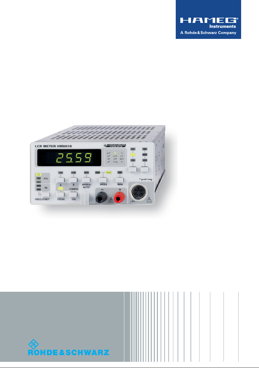
HM8018
LCR-Meter
Benutzerhandbuch
User Manual
*5800454002*
5800454002
Version 02
Test & Measurement
Benutzerhandbuch / User Manual
Page 2

Allgemeine Hinweise zur CE-Kennzeichnung
Allgemeine Hinweise zur CEKennzeichnung
HAMEG Messgeräte erfüllen die Bestimmungen
der EMV Richtlinie. Bei der Konformitätsprüfung
KONFORMITÄTSERKLÄRUNG
HAMEG Instruments GmbH
Industriestraße 6
D-63533 Mainhausen
Die HAMEG Instruments GmbH bescheinigt die
Konformität für das Produkt
Bezeichnung: LCR-Meter
Typ: HM 8018
mit: HM8001-2
mit den Bestimmungen des Rates der
Europäischen Union zur Angleichung der
Rechtsvorschriften der Mitgliedstaaten
z betreffend elektrische Betriebsmittel
zur Verwendung innerhalb bestimmter
Spannungsgrenzen (2006/95/EG) [LVD]
z über die elektromagnetische Verträglichkeit
(2004/108/ EG) [EMCD]
z über die Beschränkung der Verwendung
bestimmter gefährlicher Stoffe in Elektround Elektronikgeräten (2011/65/EG) [RoHS]
übereinstimmt.
Die Übereinstimmung mit LVD und EMCD wird
nachgewiesen durch die Einhaltung folgender
Normen:
EN 61326-1: 07/2013
EN 55011: 11/2014
EN 61010: 04/ 2015
EN 61000-4-2: 12/2009
EN 61000-4-3: 04/2011
EN 61000-4-4: 04/2013
EN 61000-4-5: 03/2015
EN 61000-4-6: 08/2014
EN 61000-4- 8: 11/2010
EN 61000-4-11: 02/2005
Bei der Beurteilung der elektromagnetischen
Verträglichkeit wurden die Störaussendungsgrenzwerte für Geräte der Klasse B sowie
die Störfestigkeit für Betrieb in industriellen
Bereichen zugrunde gelegt.
Datum 21.9.2015
Unterschrift
Holger Asmussen
General Manager
2
Änderungen vorbehalten
werden von HAMEG die gültigen Fachgrund- bzw.
Produktnormen zu Grunde gelegt. Sind unterschiedliche Grenzwerte möglich, werden von HAMEG die härteren Prüfbedingungen angewendet.
Für die Störaussendung werden die Grenzwerte
für den Geschäfts- und Gewerbebereich sowie für
Kleinbetriebe angewandt (Klasse 1B). Bezüglich
der Störfestigkeit nden die für den Industriebereich geltenden Grenzwerte Anwendung.
Die am Messgerät notwendigerweise angeschlos-
senen Mess- und Datenleitungen beeinussen
die Einhaltung der vorgegebenen Grenzwerte in
erheblicher Weise. Die verwendeten Leitungen
sind jedoch je nach Anwendungsbereich unter-
schiedlich. Im praktischen Messbetrieb sind daher
in Bezug auf Störaussendung bzw. Störfestigkeit
folgende Hinweise und Randbedingungen unbedingt zu beachten:
1. Datenleitungen
Die Verbindung von Messgeräten bzw. ihren
Schnittstellen mit externen Geräten (Druckern,
Rechnern, etc.) darf nur mit ausreichend abgeschirmten Leitungen erfolgen. Sofern die Bedienungsanleitung nicht eine geringere maximale
Leitungslänge vorschreibt, dürfen Datenleitungen (Eingang/Ausgang, Signal/Steuerung) eine
Länge von 3 Metern nicht erreichen und sich
nicht außerhalb von Gebäuden benden. Ist an
einem Geräteinterface der Anschluss mehrerer
Schnittstellenkabel möglich, so darf jeweils nur
eines angeschlossen sein.
Bei Datenleitungen ist generell auf doppelt abgeschirmtes Verbindungskabel zu achten. Als
IEEE-Bus Kabel ist das von HAMEG beziehbare
doppelt geschirmte Kabel HZ72 geeignet.
2. Signalleitungen
Messleitungen zur Signalübertragung zwischen
Messstelle und Messgerät sollten generell so kurz
wie möglich gehalten werden. Falls keine geringere Länge vorgeschrieben ist, dürfen Signalleitungen (Eingang/Ausgang, Signal/Steuerung) eine
Länge von 3 Metern nicht erreichen und sich nicht
außerhalb von Gebäuden benden. Alle Signalleitungen sind grundsätzlich als abgeschirmte
Leitungen (Koaxialkabel - RG58/U) zu verwenden.
Page 3

Inhaltsverzeichnis
Für eine korrekte Masseverbindung muss Sorge
getragen werden. Bei Signalgeneratoren müssen
doppelt abgeschirmte Koaxialkabel (RG223/U,
RG214/U) verwendet werden.
3. Auswirkungen auf die Geräte
Beim Vorliegen starker hochfrequenter elektrischer oder magnetischer Felder kann es
trotz sorgfältigen Messaufbaues über die angeschlossenen Kabel und Leitungen zu Einspeisung unerwünschter Signalanteile in das Gerät
kommen. Dies führt bei HAMEG Geräten nicht
zu einer Zerstörung oder Außerbetriebsetzung.
Geringfügige Abweichungen der Anzeige – und
Messwerte über die vorgegebenen Spezikationen
hinaus können durch die äußeren Umstände in
Einzelfällen jedoch auftreten.
HAMEG Instruments GmbH
English 14
Deutsch
Allgemeine Hinweise
zur CE-Kennzeichnung 2
LCR-Meter HM8018 4
Technische Daten 5
Wichtige Hinweise 6
Sicherheit 6
Verwendete Symbole 6
Gewährleistung und Reparatur 6
Servicehinweise und Wartung 6
Betriebsbedingungen 7
Inbetriebnahme des Moduls 7
Bedienungselemente HM8018 8
Bedienung des HM8018 9
Messfrequenz 9
Messspannung 9
Messbereiche 10
Die Messbereichsautomatik 10
Die manuelle Messbereichswahl 10
Polarisation (Bias) 11
Auswahl der Messfunktion 11
Die Auto-Messfunktion 11
Mathematische Funktionen 11
Anschließen von Bauteilen 12
Leerlauf/Kurzschluss-Abgleich 12
Speichern der Konguraion 12
Einstellen der Netzfrequenz 12
Messgenauigkeit 13
Änderungen vorbehalten
3
Page 4
Messfunktionen: L, C, R, Θ, Q, D, |Z|
Grundgenauigkeit 0,2 %
5 Messfrequenzen: 100 Hz, 120 Hz, 1 kHz, 10kHz, 25 kHz
Maximale Auflösung: 0,001 Ω, 0,001 pF, 0,01 μH
2- und 4-Draht Messung
Parallel- und Serienmodus
Vorspannung für Elektrolytkondensatoren zuschaltbar
Grundgerät HM8001-2 erforderlich
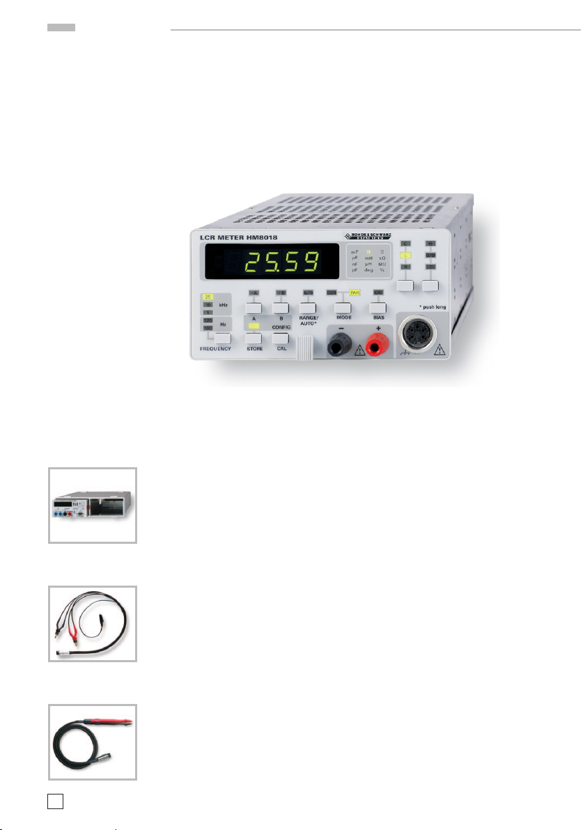
LCR-Meter HM8018
HM8 018
LCR-Meter
HM8018
Grundgerät HM8001-2
Option HZ18 Kelvin-Messleitung
Option HZ19 SMDMesspinzette
4
Änderungen vorbehalten
Messfunktionen: L, C, R, Θ, Q, D |Z|
Grundgenauigkeit 0,2 %
5 Messfrequenzen: 100 Hz, 120 Hz, 1 kHz, 10 kHz, 25 kHz
Maxim ale Auösung : 0 ,001 Ω, 0,001 pF, 0,01 µH
2- und 4-Draht Messung
Parallel- und Serienmodus
Vorspannung für Elektrolytkondensatoren zuschaltbar
Grundgerät HM8001-2 erforderlich
Page 5

Technische Daten
LCR-METER HM8018
bei 23 °C nach einer Aufwärmzeit von 30 Minuten
Messfunktionen und -bedingungen
Messbare Kenngrößen: R, L, C, Θ, Q/D, |Z|
Schaltungsart: seriell, parallel
Messart: 2-Draht, 4-Draht
Messbereiche: R: 0,001 Ω ... 99,9 MΩ
C: 0,001 pF ... 99,9 mF
L: 0,01 µH ... 9999 H
Q: 0,0001 ... 99,9
D: 0,0001 ... 9,9999
Θ
: -180,00° ... +180,00°
Grundgenauigkeit: 0,2 %
Messfrequenzen: 100 Hz, 120 Hz, 1 kHz, 10 kHz,
25 kHz
Frequenzgenauigkeit: ±100 ppm
(außer 120 Hz: 120.2 Hz
Messspannung: 0,5 V
±10% (Leerl auf)
eff
±100 ppm)
Messrate: 2 Messungen/Sekunde
Messbereichswahl: automatisch, manuell
DC Bias Spannung: 1 V ±10%
Nullpunkt: Leerlauf- und Kurzschluss-
abgleich
Abgleichbedingungen: Kurzschluss:R <10 Ω
Z <15 Ω
Leerlauf: Z >10 kΩ
Messgenauigkeit
mit D‹0,1 bzw. Q›10:
(A
= 1 für D<0,1) L: Ae = Af x Ad (1 + Lx/L
d
Z: A
R: A
mit D ≥0,1: A
C: Ae = Af x Ad (1 + Cx/C
= Af (1 + Zx/Z
e
= Af x Ad (1 + Rx/R
e
= √ 1 + D
e
max
2
x
+ Z
max
max
max
+ C
+ L
min/Zx
+ R
min/Cx
min/Lx
min/Rx
mit den Parametern: Cx, Lx, Zx, Rx = Messwert
A
= 0,2% bei f = 100 Hz, 120 Hz, 1 kHz
f
A
= 0,3% bei f = 10 kHz
f
A
= 0,5% bei f = 25 kHz
f
Parameter Auto Range
C
160 µF/f (f in kHz)
max
C
53 pF/f (f in kHz)
min
L
480 H/f (f in kHz)
max
L
0,16 mH/f (f in kHz)
min
Z
, R
3 MΩ
max
max
Z
, R
0,5 Ω
min
min
Genauigkeit des
Verlustfaktors:
Genauigkeit des
Gütefaktors:
Genauigkeit des
Phasenwinkels:
A
De = ± ——
Q
Qe = ————
180 A
Θ =
e
100
2
x
1 ± Qx · D
—— · ——
π
· D
e
100
e
e
Anzeige
5-stellige 7-Segment LED-Anzeige mit Vorzeichen
Anzeigearten:
Messwert
Verhältnis
Offset }
rel. Offset
Berechnung erfolgt
aus Messwert und
gespeichertem Referenzwert
Verschiedenes
Die Eingänge sind kurzschlussfest und kurzzeitig
überspannungsfest bis 100 V
bei einer maximalen
DC
Energieaufnahme von 1 J.
Eine Gerätekonguration kann gespeichert werden.
Arbeitstemperatur: +5 °C ... +40 °C
Lagertemperatur: –20 °C ... +70 °C
max. rel. Luftfeuchtigkeit: 5%... 80% (ohne Kondensation)
Versorgung (von Grundgerät):
+5 V/300 mA
+5,2 V/50 mA
-5,2 V/50 mA
(
∑ = 2 W)
Gehäuse (ohne 22 pol. Flachstecker):
(B x H x T) 135 x 68 x 228 mm
Gewicht: ca. 500 g
)
)
)
)
Im Lieferumfang enthalten:
LCR-Meter HM8018, Bedienungsanleitung
Optionales Zubehör:
HZ10S Silikon-Messleitung
HZ10R Silikon-Messleitung
HZ10B Silikon-Messleitung
HZ17 Kelvin-Messleitung (4-Draht)
mit Prüfspitze
HZ18 Kelvin-Messleitung (4-Draht)
mit Krokodilklemmen
HZ19 Kelvin-Messleitung (4-Draht)
mit SMD-Messpinzette
Änderungen vorbehalten
5
Page 6
Wichtige Hinweise
Wichtige Hinweise
HAMEG Module sind normaler weise nur in
Verbindung mit dem Grundgerät HM 8001-2 ver-
wendbar. Für den Einbau in andere Systeme ist
darauf zu achten, dass die Module nur mit den
in den technischen Daten spezi zierten Versorgungsspannungen betrieben werden. Nach dem
Auspacken sollte das Gerät auf mechanische Beschädigungen und lose Teile im Innern überprüft
werden. Falls ein Transportschaden vorliegt, ist
sofor t de r Lieferant zu informier en. Da s Ge rät dar f
dann nicht in Betrieb gesetzt werden.
Sicherheit
Diese s Gerät ist g emäß VDE 0 411 Teil 1, Sicherhe its bestim mungen für elektrische Mess-, Steuer-,
Regel- und Laborgeräte, gebaut und geprüft und
hat das Werk in sicherheits technisch einwand-
freiem Zustand verlassen. Es entspricht damit
auch den Bestimmungen der europäischen Norm
EN 61010-1 bzw. der internationalen Norm IEC
1010-1. Den Bestimmungen der Schutz klasse I
entsprechend sind alle Gehäuse- und Chassisteile
mit dem Netzschutzleiter verbunden (für Module
gilt dies nur in Verbindung mit dem Grundgerät).
Modul und Grundgerät dürfen nur an vor schrift smäßigen Schutz kontakt-Steckdosen betrieben
werden. Das Auftrennen der Schutzkontaktverbindung innerhalb oder außerhalb der Einheit ist
unzulässig.
Wenn anzunehmen ist, dass ein gefahrloser Betrieb nicht mehr möglich ist, so ist das Gerät außer
Betrieb zu setzen und gegen unabsichtlichen
Betrieb zu sichern.
Diese Annahme ist berechtigt,
– wenn das Gerät sichtbare Beschädigungen
aufweist
– wenn das Gerät lose Teile enthält,
– wenn das Gerät nicht mehr arbeitet,
– nach längerer Lagerung unter ungünstigen
Verhältnissen (z.B. im Freien oder in feuchten
Räumen).
Beim Öffnen oder Schließen des Gehäuses muss
das Gerät von allen Spannungsquellen getrennt
sein. Wenn danach eine Messung oder ein Abgleich am geöffneten Gerät unter Spannung
6
Änderungen vorbehalten
unvermeidlich ist, so darf dies nur durch eine
Fachkraft geschehen, die mit den damit verbun-
denen Gefahren vertraut ist.
Verwendete Symbole
Achtung –
Bedienungsanleitung beachten
Vorsicht Hochspannung
Erdanschluss
Gewährleistung und Reparatur
Unsere Geräte unterliegen einer strengen Quali-
tätskontrolle. Jedes Gerät durchläuft vor dem
Verlassen der Produktion einen 10-stündigen
„Bur n in -Test“. Ansc hl ießend erfolg t ein umfangreicher Funktions- und Qualitätstest, bei dem alle
Betriebsar ten und die Einhaltung der technischen
Daten geprüft werden. Die Prüfung erfolgt mit
Prüfmitteln, die auf nationale Normale rückführ-
bar kalibriert sind. Es gelten die gesetzlichen
Gewährleistungsbestimmungen des Landes, in
de m das Pr odukt er wor ben wurde . Be i Bean sta ndungen wenden Sie sich bitte an den Händler, bei
dem Sie das Produkt er worben haben.
Das Produkt darf nur von dafür
autorisiertem Fachpersonal geöffnet
werden. Vor Arbeiten am Produkt oder
Öffnen des Produkts ist dieses von der
Versorgungsspannung zu trennen,
sonst besteht das Risiko eines elektri-
schen Schlages.
Abgleich, Auswechseln von Teilen, Wartung und
Reparatur darf nur von autorisier ten Fachkräften
ausgeführt werden. Werden sicherheitsrelevante
Teile (z.B. Netzschalter, Netztrafos oder Siche-
rungen) ausgewechselt, so dürfen diese nur
durch Originalteile ersetzt werden. Nach jedem
Austausch von sicherheitsrelevanten Teilen ist
eine Sicherheitsprüfung durchzuführen (Sichtprüfung, Schutzleiter test, Isolationswider stands-,
Ableitstrommessung, Funktionstest). Damit wird
sichergestellt, dass die Sicherheit des Produkts
erhalten bleibt.
Page 7

Wichtige Hinweise
Servicehinweise und Wartung
Verschiedene wichtige Eigenschaften der Messgeräte sollten in gewissen Zeitabständen genau
überprüft werden. Dazu dienen die im Funktionstest des Manuals gegebenen Hinweise.
Löst man die beiden Schrauben am GehäuseRückdeckel des Grundgerätes HM 8001-2, kann
der Gehäusemantel nach hinten abgezogen
werden.
Beim späteren Schließen des Gerätes ist darauf
zu achten, dass sich der Gehäusemantel an allen
Seiten richtig unter den Rand des Front- und
Rückdeckels schiebt. Durch Lösen der beiden
Schrauben an der Modul-Rückseite, lassen sich
beide Chassisdeckel entfernen. Beim späteren
Schließen müssen die Führungsnuten richtig in
das Frontchassis einrasten.
Betriebsbedingungen
Die zulässige Umgebungstemperatur während
des Betriebes reicht von +5 °C...+40 °C. Während
der Lagerung oder des Transports darf die Tem-
peratur zwischen –20 °C und +70 °C betragen. Hat
sich während des Transports oder der Lagerung
Kondenswasser gebildet, muss das Gerät ca.
2 Stunden akklimatisiert werden, bevor es in
Betrieb genommen wird. Die Geräte sind zum
Gebrauch in sauberen, trockenen Räumen be-
stimmt. Sie dürfen nicht bei besonders großem
Staub- bzw. Feuchtigkeitsgehalt der Luft, bei Ex-
plosionsgefahr sowie bei aggres siver chemischer
Einwirkung betrieben werden. Die Betriebslage
ist beliebig. Eine ausreichende Luftzirkulation
(Konvektionskühlung) ist jedoch zu gewährleisten.
Bei Dauerbetrieb ist folglich eine horizontale
oder schräge Betriebslage (Aufstellbügel) zu
bevorzugen. Die Lüftungslöcher dürfen nicht
abgedeckt sein.
Einschieben der Module. Diese können nach
Belieben in der rechten oder linken Einschub-
öffnung betrieben werden. Vor dem Einschieben
oder bei einem Modulw echsel ist das Grundgerät
auszuschalten. Der rote Tastenknopf POWER
(Mitte Frontrahmen HM 8001-2) steht dann heraus, wobei ein kleiner Kreis (o) auf der oberen
Tasten schmalseite sichtbar wird. Falls die auf
der Rückseite bendlichen BNC-Buchsen nicht
benut zt we rden, sollte ma n evt l. ange sch lossene
BNC-Kabel aus Sicherheits gründen entfernen.
Zur sicheren Verbindung mit den Betriebsspannungen müssen die Module bis zum Anschlag
ei nge schob en werden. Sola nge di es nicht de r Fa ll
ist, besteht keine Schutzleiterverbindung zum
Gehäuse des Modules (Büschelstecker oberhalb
der Steckerleiste im Grund gerät). In diesem
Fall darf kein Mess-Signal an die Buchsen des
Modules gelegt werden.
Allgemein gilt: Vor dem Anlegen des MessSignales muss das Modul eingeschaltet und
funkt ionst üchti g se in. Is t ein Fehl er am Me ssgerät erkennbar, dürfen keine weiteren Messungen
durchgeführt werden. Vor dem Ausschalten des
Moduls oder bei einem Modulwechsel ist vorher
das Gerät vom Mess kreis zu trennen.
Inbetriebnahme des Moduls
Vor Anschluss des Grundgerätes ist darauf zu
achten, dass die auf der Rückseite eingestellte
Netzspannung mit dem Anschlusswert des
Netzes übereinstimmt. Die Verbindung zwischen
Schutzleiteranschluss HM 8001-2 und dem
Netz-Schutzleiter ist vor jeglichen anderen Verbindungen herzustellen (Netzstecker HM 8001-2
also zuerst anschließen). Die Inbetriebnahme
beschränkt sich dann im Wesentlichen auf das
Änderungen vorbehalten
7
Page 8
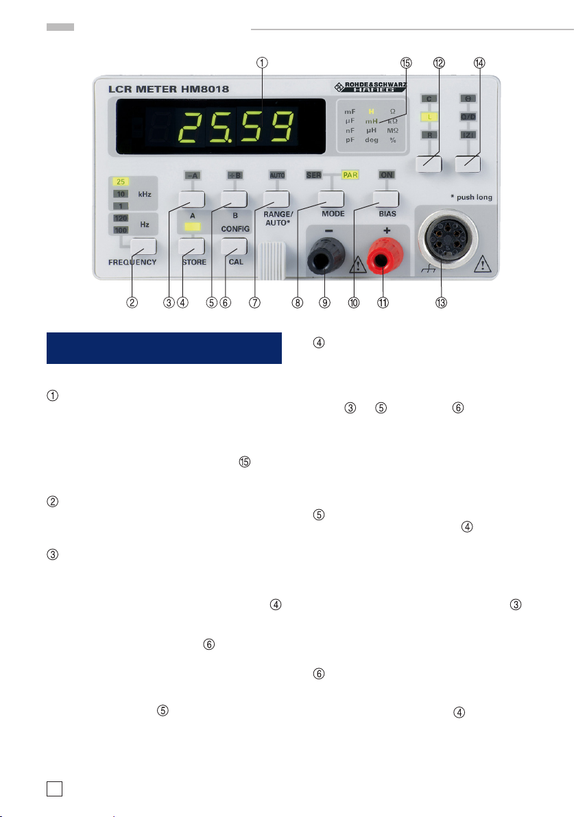
Bedienungselemente
Bedienungselemente HM8018
Display ( 7-Segment LEDs)
Die digitale Messwertanzeige gibt den Mess-
we r t mi t einer Au ösung vo n 5 Stel len wi eder.
Der Messwert wird komma- und vorzeichen-
richtig angezeigt. Die Einheit des Messwerts
wird von einer LED im Einheitenfeld
zeigt. Bei Overow zeigt das Display ----- an.
FREQUENCY (Taste)
Auswahl der Messfrequenz: 100 Hz, 120 Hz,
1 kHz, 10 kHz, 25 kHz
A (Taste) und –A (LED)
Durch Drücken der Taste A wird der ak-
tuelle Messwert im Speicher A (flüchtig)
gespeichert, wenn sich das HM8018 im
Speicherbetrieb befindet (STORE-LED
leuchtet). Der Messwert kann auch im nicht-
üchtigen Speicher abgelegt werden (siehe
Beschreibung der CAL-Taste
LED –A , be ndet sich da s Messg erä t im Rel a-
ti vmod us, d. h. im Disp lay wird die Di ffe ren z vo n
aktue llem Mess wert – Mes swert im S peicher A
angezeigt. Leuchten sowohl die LED –A als
auch die LED ÷B
, so zeigt das Display
100 * (aktueller Messwert – Messwert im
Speicher A) / Messwert in Speicher B
Relativmodus wird durch erneutes Drücken
de r Tas te A verl ass en und die LE D –A erli scht.
8
Änderungen vorbehalten
ange-
). Leuchtet di e
an. Der
S TORE (Tas te)
Nach Drücken der STORE-Taste leuchtet die
ob erhalb de r Tas te bendl ich e LE D au f und das
Messgerät bendet sich im Speicherbetrieb.
Anschließend wird durch Betätige n der Tasten
, ÷B oder CONF IG der ak tuelle Mes-
–A
swer t im Speicher A , B oder die Eins tellungen
im Kongurationsspeicher abgelegt. Im Display erscheint kurz Sto.A, Sto.b oder Sto.C.
Wird e ine andere Taste gedrückt, v erlässt man
den Speicher-Modus. Die STORE-LED erlischt
nach Verlassen der Speicherbetriebs.
B (Taste) und ÷B (LED)
Im Speicherbetrieb (LED
durch Drücken der Taste B der aktuelle Messwert im Speicher B (flüchtiger Speicher)
abgelegt. In der Standard-Betriebsart leuchtet
die LED ÷B nach dem Betätigen auf und im
Display wird das Verhältnis
bzw.
100*(Messwert - A)/B
aktiviert ist) angezeigt. Durch erneutes Drücken der Taste B wird dieser Modus ver lassen
und die LED ÷B erlischt.
CAL/CONFIG (Taste)
In d er normalen Betriebsart wir d mit der CAL-
Taste das Abgleichmenu aktiviert. Im Speicherbetrieb (STORE-LED
die aktuellen Einstellungen durch Drücken der
CONFIG-Taste gespeichert (nicht-üchtig).
Diese Einstellungen werden nach dem Ein-
schalten geladen.
leuchtet) wird
100*Messwert/B
(wenn -A auch
leuchtet) werden
Page 9
Bedienung des HM8018
instrument measures impedance that is out of its current range,
the instrument switches one range up or one range down and
makes a new measurement. If this measurement is within the
validity domain of this new range the instrument will display the
value, if not, the range change process will be repeated. There is
a built in hysteresis in the order of 10% to prevent multiple range
changes when a component is on the limit of range boundary.
The chart below gives the limits of range changes.
voltage at the component terminals
for the different ranges
0,5
1,E-01 1,E+00 1,E+01 1,E+02 1,E+03 1,E+04 1,E+05 1,E+06 1,E+07 1,E+08
Remarks: when measuring certain types of inductors it may
occurs that the HM8018-2 switches indefinitely between two
ranges. This due to the fact that generally the inductor value
depends of the current going through, the HM8018-2 will
gives different values from one range to an other because the
source resistance changes. This variation from one range to
another may be higher than the automatic mode hysteresis
that creates irresolution. So it is necessary to switch on
manual mode to fix the range.
R ANGE/AUTO* (Tas te)
Bereichswahltaste und Taste zur Aktivierung
der Messbereichsautomatik. In der manuellen
Betriebsart (AUTO LED ist aus) erfolgt die Umschaltung in den nächst höheren Messbereich
durch (mehrmaliges) Betätigen dieser Taste. Der
aktuelle Messbereich Ran. X (X = 1...6) erscheint
kurz in der Anzeige. Wird die Taste lange ge-
drückt, wechselt das HM8018 in die automatische
Messbereichswahl und die AUTO-LED leuchtet.
Wird bei aktivierter Messbereichsautomatik die
AUTO-Taste erneut gedrückt, wechselt das Gerät
in die manuelle Betriebsart, wobei der aktuelle
Messbereich übernommen und kurz im Display
anzeigt wird.
MODE (Taste)
Mit dieser Taste wird zwischen Par allel- bzw.
Serienmodus umgeschaltet.
–/+ (Buchsen)
Eingangsbuchsen (4 mm Bananenbuchsen)
zum Anschluss der Messkabel (2-DrahtMessung)
BIAS (Taste) und ON (LED)
Durch Betätigen der BIAS-Taste wird eine
Vorspannung von 1 V
der Ausgangsspan-
DC
nung überlagert. Bei aktivierter Bias-Funktion
leuchtet die ON-LED. Bei polarisierten Kon-
densatoren sollte diese Funktion aktiviert
werden, um eine Verpolung aufgrund der
Sinusspannung zu vermeiden. Wird die BIAS-
Taste erneut betätigt, wird die Bias-Funktion
deaktiviert und die BIAS-LED erlischt.
FUNCTION (Taste)
Mit dieser Taste werden die Hauptmessfunk-
tionen des HM8018 ausgewählt. Im seriellen
Modus werden je nach gewählter Messfunk-
, Ls oder Rs im Display angezeigt, im
tion C
s
parallelen Modus C
, Lp oder Rp.
p
Kelvin-Eingang (5polige Diodenbuchse)
Anschluss des 4-Draht-Messkabels HZ18
FUNCTION (Taste)
Mit dieser Taste werden die Sondermessfunk-
tionen des HM8018 ausgewählt: Phasenwinkel
Θ
(-180°...+180°), Impedanz |Z|, Verlustfaktor
D und Gütefaktor Q. Bei aktivierter Kapa-
zitätsmessung wird der Verlustfaktor, bei
Widerstands- bzw. Induktivitätsmessung der
Gütefaktor angezeigt.
Einheitenfeld (LEDs)
Anzeige der aktuellen Einheit
Bedienung des HM8018
Messfrequenz
Das LCR Meter HM8018 verfügt über 5 Messfrequenzen
mit einer Genauigkeit von ±0,01%. Die Testfrequenz wird
durch mehrmaliges Drücken der Taste FREQUENCY
ausgewählt. Die entsprechende LED leuchtet. Bei
einem Frequenzwechsel kann es zu einem Wechsel
des Modells (seriell bzw. parallel) kommen, wenn
sich das Gerät im AUTO-Modus bendet und wenn die
Impedanz den Schwellwert von 1000 Ω überschreitet.
Bei hohen Impedanzen und einer Netzfrequenz von
50 Hz kann es bei einer Testfrequenz von 120 Hz zu einer
instabilen Messwertanzeige aufgrund von Frequenzun
terdrückungen kommen. Dies gilt auch für eine Testfrequenz von 100 Hz bei einer Netzfrequenz von 60 Hz.
Abhängig von der Netzfrequenz ist die Messfrequenz
entsprechend der folgenden Tabelle zu wählen:
Netzfrequenz
50 Hz
Netzfrequenz
60 Hz
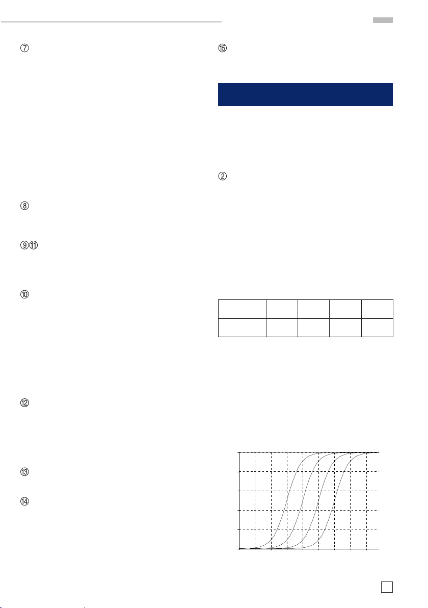
Messspannung
Das HM8018 erzeugt eine Sinusspannung von
0,5 V
eff
beträgt ±5% bei Frequenzen <10 kHz und ±10%
bei 25 kHz. Diese Spannung wird an den Prüing
durch eine Quellenwiderstand angelegt, wobei
die Spannung an den Bauteilanschlüssen immer
0,4
0,3
0,2
Spannung (V)
0,1
0
100 Hz 1 kHz 10 kHz 25 kHz
120 Hz 1 kHz 10 kHz 25 kHz
(unbelastet). Die Genauigkeit der Amplitude
Spannung an den Bauteilanschlüssen in den
verschiedenen Messbereichen
R1,R2
R3 R4
Impedanz
Änderungen vorbehalten
-
R5,R6
9
Page 10

Bedienung des HM8018
<0,5 V ist. Der Ausgangswiderstand ist abhängig
vom Messbereich. Der Graph zeigt dieSpannung
an den Bauteilanschlüssen in Abhängigkeit von
Impedanz und Messbereich (R1: Bereich 15 Ω...
R6: Bereich 100 MΩ).
Messbereiche
Das HM8018 verfügt über 6 Messbereiche (R1R6), die manuell oder automatisch ausgewählt
werden können. In den einzelnen Bereichen ist
der Ausgangswiderstand etwa genauso groß wie
der halbe Bereichsendwert. Jedoch in den beiden
Berei che R1 un d R6 ist der jeweili ge Ausg angswide rstand so gr oß wi e in den Bere ichen R2 und R5.
Achtung:
Die Messbereiche von Kapazität und Induktivität
sind abhängig von der Messfrequenz. Große
Kapazitäten bzw. kleine Induktivitäten werden in
niedrigen Bereichen und kleine Kapazitäten bzw.
große Induktivitäten in den hohen Messbereichen
gemessen. Die unten stehende Tabelle zeigt den
Messbereich bezogen auf den Bauteiltyp und die
Messfrequenz.
Be-
Ausgangs-
reich
Wider-
stand
R1 100 Ω 1mΩ –
R2 100 Ω 15 Ω –
R3 1 kΩ 330Ω –
R4 10 kΩ 3,3 kΩ –
R5 100 kΩ 33 kΩ –
R6 100 kΩ 3 30 k Ω -
Wider-
stand
15Ω
330Ω
3,3 kΩ
33 kΩ
330 kΩ
100MΩ
Induk-
tivität
(H)
0,01 µH –
2,4/f
2,4 /f –
52,5/f
52,5 /f –
525/f
525/f –
5252/f
5252/f –
52520/f
52520/f
9999
Kapazität
99,9 mF –
10,6/f mF
10,6/ f mF –
482/f µF
48 2/f µ F –
48,2/f µF
48, 2/f µ F –
4,82/f µF
4,8 2/f µ F –
0,48/f µF
0,4 8/f µ F –
0,001 pF
f = Messfrequenz in Hz
Die Messbereichsautomatik
Bei aktivier ter Messbereichsautomatik wählt das
HM8018 den für eine präzise Mes sung geeigneten
Messbereich. Misst das LCR-Meter eine Impedanz, die größer als der aktuelle Messbereich
ist, schaltet es in den nächst höheren oder niedrigeren Messb ereich und füh rt eine neue M essung
durch. Ist dieses Messergebnis innerhalb des
gültigen Bereichs des neues Messbereichs, zeigt
das Messgerät den Wert an. Ist das Ergebnis außerhalb des Bereichs, er folgt wieder ein Bereichs-
10
Änderungen vorbehalten
wechsel. Die Hy sterese von etwa 10 % verhinder t
mehrfaches Bereichsumschalten, wenn sich der
Messwert in der Nähe des Bereichsendwerts
bendet. Die folgende Tabelle zeigt die Grenzen
für den Bereichswechsel:
Bereichs-
wechsel
1 to 2
2 to 3
3 to 4
4 to 5
5 to 6
|Z|
|Z| > 15 Ω
|Z| > 330 Ω
|Z| > 3,3 kΩ
|Z| > 33 kΩ
|Z| > 330 kΩ
Bereichs-
wechsel
2 to 1
3 to 2
4 to 3
5 to 4
6 to 5
|Z|
|Z| < 13,5 Ω
|Z| < 300 Ω
|Z| < 3 kΩ
|Z| < 30 kΩ
|Z| < 300 kΩ
Hinweis:
Bei der Messung bestimmter Induktivitäten kann
es vorkommen, dass das HM8018 fortwährend
den Messbereich wechselt. Dies beruht auf
der Tatsache, dass sich die Induktivität mit der
Frequenz ändert. Deshalb misst das LCR-Meter
unterschiedliche Werte in den verschiedenen
Messbereichen, da sich der Quellenwiderstand
ändert.Diese Veränderung des Messwerts kann in
den verschiedenen Bereichen größer sein als die
Hysterese im Auto-Mode, was zu kontinuierlichen
Br eichsums chalten führ t. De shalb ist es notwe ndig, in die manuelle Betriebsart zu wechseln.
Die manuelle Messbereichswahl
Wenn mehr ere ähnliche B auteile zu messen sind,
können die Messungen beschleunigt werden,
wenn man, statt im Auto-Modus, im manuellen
Betrieb misst.
Drücken Sie nach der Messung des 1. Bauteils
die AUTO-Taste. Der aktuelle Messbereich wird
übernommen und kurz im Display angezeigt.
Es besteht die Möglichkeit, diese Einstellung zu
speichern. Drücken Sie zuerst die STORE-Taste
und anschließend die CONFIG-Taste. Wenn die
Impedanz des Bauteils größer als der 50fache
Nominalwert des Bereichs ist, zeigt das Display
OFL an. Ein Bereichswechsel ist not wendig. Dies
gilt nicht für den 15 Ω-Bereich, bei dem ein Bereichswechsel bei etwa 18 Ω erfolgt.
Der manuelle Modus sollte hauptsächlich bei
hochgenauen Messungen benutzt werden. Um
Messinstabilität und andere Unsicherheiten zu
vermeiden, sollte möglichst im automatischen
Modus gemessen werde.
Page 11

Bedienung des HM8018
Polarisation (Bias)
Es besteht die Möglichkeit, dem Messsignal eine
Gleichspannung (Bias) zu überlagern. Elektrolyt-
und Tantalkondensatoren benötigen eine positive
Biasspannung für eine korrekte Messung, auch
wenn das Messsignal nicht groß genug ist, um
die Bauteile zerstören. Die interne Vorspannung
) erlaubt die Messungen möglichst reali-
(1 V
DC
tätsnah durchzuführen. Die interne Biasspannung
ermöglicht außerdem Messungen an Halbleitern.
Um die BIAS-Funktion zu aktivieren ist die BIAS-
Taste zu drücken. Die darüber bendliche ONLED leuchtet auf. Wird die Taste ein weiteres Mal
gedrückt, wird die Bias-Spannung deaktiviert und
die LED erlischt.
Der zu testende Kondensator muss mit der
richtigen Polarität angeschlossen werden, d.h.
der positive Pol des Kondesators wird an die rote
Buchse angeschlossen. Die Biasspannung funktioniert nur bei der Kapazitätsmessung
Auswahl der Messfunktion
Die gewünschte Messfunktion wird durch Drücken
der Tasten
werden die Hauptmessfunktionen (R,L,C) aus-
gewählt, mit der Taste
tionen (Q, D, Impedanz und Phase).
und ausgewählt. Mit der Taste
die Sekundärmessfunk-
Q = 500
D = 0,002
D = Q = 1
|Z| = 1000
D = Q = 1
Q = 500
D = 0,002
Mathematische Funktionen
Ω
D = 500
Q = 0,002
R
D = 500
Q = 0,002
Um den Ver lus tfakto r zu mess en. muss zuer st die
Kapazitätsmessung ausgewählt werden, sonst
wird der Gütefaktor angezeigt.
Die Auto-Messfunktion
Das HM8018 kann in den meisten Fällen den
Bauteiltyp bestimmen. Es gibt 3 verschiedene
Automatismen: die automatische Impedanzbereichswahl (siehe Kapitel Messbereichsautomatik), die automatische Wahl der Schaltunsgart
(seriell/parallel) und die Auto-Messfunktion.
Diese drei Automatismen sind aktiv, sobald sich
das HM8081 im Auto-Modus (AUTO-LED leuch-
tet) bendet. Die einzelnen Automatismen können durch Tastendruck deaktiviert werden. Die
manuelle Messbereichswahl schaltet alle drei
Automatismen aus. Bendet sich das HM8018
im Auto-Modus, ist die Messfunktion abhängig
von der Impedanz des Bauteils. Die folgende
Skizze zeigt, wie das LCR-Meter die Messf unktion
auswählt.
Neben der Anzeige von Standardparametern wie
Widerstand, Induktivität oder Kapazität kann das
HM8018 den Offset und das Verhältnis anzeigen.
Diese Funktionen können nur mit den Standardmessfunktionen benutzt werden. Offset und Verhältnis beziehen sich auf den im entsprechenden
Speicher A bzw. B hinterlegten Messwert.
Vorgehensweise bei der Offset-Messung:
1. Das Referenz-Bauteil an das HM8018 anschließen.
2. Durch Drücken der STORE-Taste und an-
schließend der Taste A wird der momentane
Messwer t im Speicher A abgelegt. Im Display
erscheint kurz Sto.A.
3. Durch Drücken der Taste A leuchtet die LED –A
auf. Der im Display angezeigte Wert ist dann
die Differenz
Messwert - Speicher A
.
Eine Messung des Verhältnisses ist möglich, indem man die Taste –A bei der oben beschrieb enen
Vorgehensweise durch die Taste ÷B ersetzt.
Änderungen vorbehalten
11
Page 12

Bedienung des HM8018
Vorgehensweise bei der Messung des prozentualen Offsets:
1. Das Referenz-Bauteil an das HM8018 anschließen.
2. Durch Drücken der STORE-Taste und an-
schließend der Taste A wird der momentane
Messwer t im Speicher A abgelegt. Im Display
erscheint kurz Sto.A.
3. Durch Drücken der STORE-Taste und an-
schließend der Taste B wird der momentane
Mess wert im Sp eicher B abgel egt. Im Displ ay
erscheint kurz Sto.B.
4. Durch Drücken der Tasten A und B leuchteten
die LEDs –A und ÷B auf. Angezeigt wird dann
100*(Messwert-Speicher A) / Speicher B
mit einer Auösung von 0,01 %.
Der Anzeigeumfang bei der Verhältnismessung
beträgt -100.00% ... +999.99%.
in %
Anschließen von Bauteilen
Es gibt zwei Möglichkeiten, Bauteile an den
HM8018 anzuschließen. Für schnelle Messungen
können die 4 mm Bananenbuchsen benutzt
werden. Das Bauteil wird dann entweder über
Messkabel angeschlossen oder direkt an den
Buchs en, die dazu aufg edreht werd en können, be-
fe sti gt. Diese 2-Dr aht-M ess ung ist je doch nicht so
genau wie die 4-Draht-Messung. Für hochgenaue
Messungen sollte die HZ18 Kelvin-Messleitung
verwendet werden. Diese Messleitung verwendet
eine Kelvin-Verbindung, die parasitäre Impe-
danzen minimiert. Nach einer Veränderung der
Messanordnung muss ein Open/Short-Abgleich
durchgeführt werden. Dies ist ebenfalls bei einer
Änderung der Messfrequenz notwendig.
Bauteils erfolgen, z.B. sollte die Anordnung der
Kabel nicht verändert werden. Außerdem sollte
die Messkabel frei liegen, d.h. es solten sich
weder Hände noch metallsiche Gegenstände in
de r Nähe bende n, die die Me ssu ng beei nuss en
könnten.
Vorgehensweise beim Leerlauf/KurzschlussAbgleich:
1. Drücken der CAL-Taste. Das Display zeigt
OP.-Sh. an und die LEDs –A und AUTO blinken.
2. Um den Short-Abgleich durchzuführen, drückt
man die AU TO-Taste, wobei die Messleitungen
kurzgeschlossen sein müssen
3. Um den Open-Abgleich durchzuführen, drückt
man die -A-Taste, wobei die Enden der Mess-
leitungen offen sein müssen.
Der Abgleich selbst dauert ein paar Sekunden
und bei erfolgreichem Abgleich erscheint im
Displ ay die Meldung PASS, bei nicht erfolgreichem
Abgleich FAIL. Der Short-Abgleich ist gültig für
Impedanzen bis zu 15 Ω und Widerstände bis
10 Ω. Der Open-Abgleich ist gültig für Impedanzen
größer 10 kΩ.
Speichern der Konguration
Wird b eim Einschalten die CAL-Taste gedr ückt
bis im Display dEFLT angezeigt wird, wird die
Werkseinstellung geladen. Dies beeinusst jedoch nicht die gespeicherten Abgleichwerte. Die
aktuellen Einstellungen können durch Drücken
der STORE-Taste
FI G-Taste
abgelegt werden.
und anschließend der CON-
in einem nicht-üchtigen Speicher
Achtung:
Während einer Messung, vor allem von hohen
Im pedan zen, sollten der Pr üing nicht mit Händ en
oder and eren Dingen in B erührun g kommen, da da-
durch das Messergebnis verfälscht werden kann.
Leerlauf/Kurzschluss-Abgleich
Um parasitäre Impedanzen aufgrund der Verbin-
dungen zum Prüing zu kompensieren, wird ein
Open/Short-Abgleich durchgeführt. Damit können
Messkabel und andere parasitäre kapazitive Im-
pedanzen kompensiert werden. Der Abgleich wird
nur für die aktuelle Messfrequenz durchgeführt.
Der Open/Short-Abgleich sollte unter den gleichen Bedingungen wie die spätere Messung des
12
Änderungen vorbehalten
Werkseinstellung
AUTO ON
Frequenz 1 kHz
BIAS OFF
Schaltungsart AUTO
Messbereich AUTO
Anzeige L /C/R (AUTO)
Speicher A 0.0
Speicher B 1.0
Einstellen der Netzfrequenz
Der Dual Slope A/D-Wandler des HM8018 muss
entsprechend der Netzfrequenz eingestellt werden, um eine gute Netzfrequenzunterdrückung
zu gewährleisten.
Page 13

1. Während dem Einschalten die FREUQENCY-
Taste drücken, bis im Display 50.-60 er-
scheint.
2. Um 50 Hz auszuwählen drückt man die Taste
A und für 60 Hz die AUTO-Taste. Der Dezimal-
punkt steht rechts neben der ausgewählten
Frequenz.
3. Durch Drücken der STORE-Taste wird die
ausgewählte Frequenz im nicht-üchtigen
Speicher abgelegt und das HM8018 wechselt
in den Messmodus. Bei Drücken einer anderen Taste wird wechselt das Messgerät ohne
Übernahme der Änderung in den Messmodus.
Messgenauigkeit
(mit Ad = 1 für D < 0,1 bzw. Q > 10)
= Af x Ad (1 + Cx/C
C : A
e
= Af x Ad1 + Lx/L
L : A
e
= Af (1 + Zx/Z
Z : A
e
= Af x Ad1 + Rx/R
R : A
e
A
= 0,2% bei f = 100 Hz, 120 Hz und 1 kHz
f
= 0,3% bei f = 10 kHz
A
f
= 0,5% bei f = 25 kHz
A
f
Parameter Auto Range
C
max
C
min
L
max
L
min
Z
, R
max
max
Z
, R
min
min
≥ 0,1 erhält man für die Genauigkeit:
Bei D
x
Ae= 1 + D
x
max
2
+ C
max
+ L
max
+ Z
min/Zx
+ R
max
160 µF/f
53 pF/f
480 H/f
0.16 mH/f
3 MΩ
0,5 Ω
min/Cx
min/Lx
)
min/Rx
)
)
)
Bedienung des HM8018
Genauigkeit des Verlustfaktors:
A
De = ± ——
100
e
Genauigkeit des Gütefaktors:
Q
Qe = ————
2
· D
x
1 ± Qx · D
e
e
Genauigkeit des Phasenwinkel
180 A
Θ =
—— · ——
π
e
100
Änderungen vorbehalten
13
Page 14

General information regarding the CE marking
DECLARATION OF CONFORMITY
HAMEG Instruments GmbH
Industriestraße 6
D-63533 Mainhausen
The HAMEG Instruments GmbH herewith
declares conformity of the product
Product name: LCR-Meter
Typ e: HM8018
with: HM8001-2
complies with the provisions of the Directive
of the Council of the European Union on the
approximation of the laws of the Member
States
z relating to electrical equipment for use
within dened voltage limits (2006/95/EC)
[LVD]
z relating to electromagnetic compatibility
(2004/108/EC) [EMCD]
z relating to restriction of the use of
hazardous substances in electrical and
electronic equipment (2011/65/EC) [RoHS].
General information regarding the
CE marking
HAMEG instruments fulll the regulations of the
EMC directive. The conformity test made by HAMEG is based on the actual generic and product
standards. In cases where different limit values
are applicable, HAMEG applies the strictest
standard. For emission the limits for residential,
commercial and light industry are applied. Regarding the immunity (susceptibility) the limits
for industrial environment have been used.
The measuring and data lines of the instrument
have much inuence on emission and immunity
and therefore on meeting the acceptance limits.
For different applications the lines and/or cables
used may be different. For measurement operation the following hints and conditions regarding
emission and immunity should be observed:
1. Data cables
For the connection between instruments resp.
their interfaces and external devices, (computer,
printer etc.) sufciently screened cables must
be used.
Conformity with LVD and EMCD is proven by
compliance with the following standards:
EN 61326-1: 07/2013
EN 55011: 11/2014
EN 61010: 04/ 2015
EN 61000-4-2: 12/2009
EN 61000-4-3: 04/2011
EN 61000-4-4: 04/2013
EN 61000-4-5: 03/2015
EN 61000-4-6: 08/2014
EN 61000-4- 8: 11/2010
EN 61000-4-11: 02/2005
For the assessment of electromagnetic
compatibility, the limits of radio interference
for Class B equipment as well as the immunity
to interference for operation in industry have
been used as a basis.
Date 21.9.2015
Signature
Holger Asmussen
General Manager
14
Subject to change without notice
Maximum cable length of data lines must not exceed 3 m. The manual may specify shorter lengths.
If several interface connectors are provided only
one of them may be used at any time.
Basically interconnections must have a double
screening. For IEEE-bus purposes the double
screened cable HZ72 from HAMEG is suitable.
2. Signal cables
Basically test leads for signal interconnection
between test point and instrument should be
as short as possible. Without instruction in the
manual for a shorter length, signal lines must be
less than 3 meters long.
Signal lines must be screened (coaxial cable RG58/U). A proper ground connection is required.
In combination with signal generators double
screened cables (RG223/U, RG214/U) must be used.
3. Inuence on measuring instruments.
In the presence of strong high frequency electric
or magnetic elds, even with careful setup of the
measuring equipment an inuence can not be
excluded.
Page 15

Content
This will not cause damage or put the instrument
out of operation. Small deviations of the measuring value (reading) exceeding the instrument‘s
specications may result from such conditions
in some cases.
HAMEG Instruments GmbH
Deutsch 2
English
General information regarding
CE-marking 14
LCR Meter HM8018 16
Specications 17
Important hints 18
Safety 18
Operating conditions 18
Warranty and Repair 18
Maintenance 19
Operation of the module 19
Control elements 20
Operation of the HM8018 21
Frequency 21
Test voltage 21
Measuring range 22
Auto-ranging 22
Manual range 22
Polarisation (Bias) 23
Measuring function selection 23
Auto-measurement function 23
Calculation functions 23
Component to test connexion 24
Open/short compensation 24
To perform an open or short calibration: 24
Default settings 24
Factory default parameters 24
Mains frequency setting 24
Subject to change without notice
15
Page 16

Measurement functions: L, C, R, Θ, Q, D, |Z|
Basic accuracy 0.2 %
5 measurement frequencies: 100 Hz, 120Hz, 1 kHz, 10kHz, 25 kHz
Max. Resolution: 0.001 Ω, 0.001 pF, 0.01 μH
2- and 4-wire measurement
Measurement of series and parallel components
Bias voltage for electrolyt capacitors
Mainframe HM8001-2 required for operation
LCR-Meter HM8018
HM8 018
LCR-Meter
HM8018
Mainframe HM8001-2
Option HZ18 Kelvin test lead
Option HZ19 SMD Test
Tweezers
16
Subject to change without notice
Measurement functions: L, C, R, Θ, Q, D, |Z|
Basic accuracy 0.2%
5 measurement frequencies: 100 Hz, 120 Hz, 1 kHz, 10 kHz, 25 kHz
Max. Resolution: 0.001 Ω, 0.001 pF, 0.01 µH
2- and 4-wire measurement
Measurement of serial and parallel components
Bias voltage for electrolyt capacitors
Mainframe HM8001-2 required for operation
Page 17

LCR-METER HM8018
Valid at 23 degrees C after a 30 minute warm-up period
Display
Measuring modes: R, L, C, Θ, Q/D, |Z|
Equivalent circuits: serial, parallel
Measuring method: 2-wire, 4-wire
Measuring ranges: R: 0.001 Ω ... 99,9 MΩ
C: 0.001 pF ... 99,9 mF
L: 0.01 µH ... 9999 H
Q: 0.0001 ... 99,9
D: 0.0001 ... 9,9999
Θ
: -180.00° ... +180.00°
Basic accuracy: 0,2 %
Measuring frequencies: 100 Hz, 120 Hz, 1 kHz, 10 kHz,
25 kHz
Freq. accuracy: ±100 ppm
Measuring voltage: 0.5 V
(except 120 Hz: 120.2 Hz ±100 ppm)
±10% (unloaded)
rms
Measuring rate: 2 measurements/second
Range changing: automatic, manual
DC Bias voltage: 1 V ±10%
Zero setting: Open/short circuit compensation
Compensation limits: Short: R <10 Ω
Z <15 Ω
Open: Z >10 kΩ
Measurement accuracy
with D‹0.1 or Q›10:
(A
= 1 if D<0,1) L: Ae = Af x Ad (1 + Lx/L
d
Z: A
R: A
with D ≥0 ,1: A
C: Ae = Af x Ad (1 + Cx/C
= Af (1 + Zx/Z
e
= Af x Ad (1 + Rx/R
e
= √ 1 + D
e
max
2
x
+ Z
max
max
max
+ C
+ L
min/Zx
+ R
min/Cx
min/Lx
)
min/Rx
)
)
)
with he parameters: Cx, Lx, Zx, Rx = measurement value
A
= 0.2% at f = 100 Hz, 120 Hz, 1 kHz
f
A
= 0.3% at f = 10 kHz
f
A
= 0.5% at f = 25 kHz
f
Parameter Auto Range
C
160 µF/f (f in kHz)
max
C
53 pF/f (f in kHz)
min
L
480 H/f (f in kHz)
max
L
0,16 mH/f (f in kHz)
min
Z
, R
3 MΩ
max
max
Z
, R
0,5 Ω
min
min
Dissipation factor
accuracy:
Quality factor
accuracy:
Phase angle
accuracy:
A
De = ± ——
Q
Qe = ————
180 A
Θ =
e
100
2
x
1 ± Qx · D
—— · ——
π
· D
e
100
e
e
Display
5-digits 7 segment LEDs with sign
Display parameters:
Value
% value
Deviation }
% Offset
Calculation from measurement
value and reference value
stored
Miscellaneous
The inputs are short-circuit-proof and overvoltage
protected up to 100 V
with a maximum energy
DC
consumption of 1J.
One conguration can be saved.
Operating temperature: +5 °C to +40 °C
Storage temperature: -20 °C to +70 °C
Max. relative humidity: 5%... 80% (without condensation)
Supply voltages (from HM8001-2):
+5 V/300 mA
+5.2 V/50 mA
-5.2 V/50 mA
(
∑ = 2 W)
Dimensions (without connector):
(W x H x D) 135 x 68 x 228 mm
Weight: approx. 500 g
Included in delivery:
LCR Meter HM8018, Operating manual
Optional accessories:
HZ10S 5 x silicone test lead
(measurement connection in black)
HZ10R 5 x silicone test lead
(measurement connection in red)
HZ10B 5 x silicone test lead
(measurement connection in blue)
HZ17 Kelvin test lead (4wire) with probe tips
HZ18 Kelvin test lead (4wire) with gold
plated contacts
HZ19 Kelvin test lead (4wire) with
SMD-Test-tweezers
Subject to change without notice
17
Page 18

TRIPLE POWER SUPPLY HM 8040-3
HAMEG
VOLTAGE
CURRENT CURRENTVOLTAGE
FUSE
ON/OFF
FUSE
ON/OFF
PUSH LONG
OUTPUT
Important hints
Important hints
The operator is requested to carefully reading the
following instructions and those of the mainfr ame
HM8001-2, to avoid any
operating errors and mistakes and in order to b eco-
me acquaint with the module.
After unpacking the module, check for any me-
chanical damage or loose parts inside. Should
there be any transportation damage, inform the
supplier immediately and do not put the module
into operation. This plug-in module is primarily
intended for use in conjunction with the Mainframe HM8001-2. When incorporating it into other
sys tems, the module should only b e operated with
the specied supply voltages.
Safety
The istrument must be disconnected an d secured
against unintentional operation if there is any
suggestion that safe operation is not possible.
This may occur:
– if the instrument shows visible damage,
– if the instrument has loose parts.
– if the instrument does not function,
– after long storage under unfavourable
circumstances (e.g. outdoors or in moist
environments),
– after excessive transportation stress (e.g. in
poor packaging).
When removing or replacing the metal case, the
instrument must be completely disconnected
from the mains supply. If any measurement or
calibration procedures are necessary on the
opened-up instr ument, thes e must only be ca rried
out by qualied personnel acquainted with the
danger involved.
Symbols marked on equipment:
ATTENTION refer to manual.
DANGER High voltage.
Protective ground (earth) terminal.
This instrument has been designed and tested in
accor dance with IEC Publication 1010-1, Safety
require ments for electrical equipment for measu-
rement, control, and laboratory use. It corres-
ponds as well to the the CENELEC regulations EN
61010-1. Al l ca se and chas sis parts ar e conn ected
to the safety earth conductor. Corresponding to
Safety Class 1 regulations (three-conductor AC
power cable). Without an isolating transformer,
the ins trument's po wer cable mus t be plugged into
an approved three-contact electrical outlet, which
meets International Electrotechnical Commission
(IEC) safety standards.
Warning!
Any interruption of the protective conductor
inside or outside the instrument or discon-
nection of the protective earth terminal is
likely to render the instrument dangerous.
Intentional interruption is prohibited.
18
Subject to change without notice
Operating conditions
The ambient temperature range during operation
should be between +5 °C and +40 °C and should
not exceed –20 °C or +70 °C during transport or
storage. The operational position is optional, how-
ever, the ventilation holes on the HM8001-2 and
on the plug-in modules must not be obstructed.
Warranty and Repair
Our instruments are subject to strict qualit y contr ols. Pr ior to le aving the manufa ctu ring si te , ea ch
in str ument un der goes a 10-hou r burn -in te st. Th is
is followed by extensive functional quality testing
to examine all operating modes and to guarantee
compliance with the specied technical data. The
testing is performed with testing equipment that
is calibrated to national standards. The statutor y
warranty provisio ns shall be gove rned by the la ws
of the cou ntr y in which th e pr oduct was purc has ed.
Page 19

Important hints
In case of any complaints, please contact your
supplier.
The product may only be opened by
authorized and qualied personnel.
Prior to working on the product or
before the product is opened, it must
be disconnected from the AC supply
network. Otherwise, personnel will
be exposed to the risk of an electric
shock.
Any adjustments, replacements of parts, maintenance and repair may be carried out only by
authorized technical personnel. Only original
parts may be used for replacing par ts relevant to
safe ty (e.g. power sw itch es, powe r tr ansform er s,
fuses). A safety test must always be performed
after parts relevant to safety have been replaced
(visual inspection, PE conductor test, insulation
resistance measurement, leakage current mea-
surement, functional test). This helps ensure the
continued safety of the product.
Maintenance
The most impor tant characteristics of the instruments should be per iodically c hecked according to
the instructions provided in the sections “Opera-
tional check and “Alignment procedcure. To obtain
the normal operating temperature, the mainframe
with in serted module should b e turned on at least
60 minu tes before starting the test. The specied
al ignme nt proc edure should be stri ctl y ob ser ved.
When removing the case detach mains/line cord
and any other connected cables from case of the
mainframe HM8001-2. Remove both screws on
rear panel and, holding case rmly in place, pull
ch ass is forwa rd out of case. When later re pla cing
the case, care should be taken to ensure that
it properly ts under the edges of the front and
rear frames. After removal of the two screws at
the rear of the module, both chassis covers can
be lifted. When re closi ng the modu le, ca re shou ld
be taken that the guides engage cor rectly with the
front chassis.
practically of inserting the module into the right
or left opening of the mainframe. The following
pre-cautions should be observed:
Before exchanging the module, the mainframe
must be switched off. A small circle (o) is now
revealed on the red power button in the front
centre of the mainframe.
If the BNC sockets at the rear panel of the
HM80 01-2 unit wer e in use before, the BNC cable s
should be disconnected from the basic unit for
safety reasons. Slide in the new module until the
end position is reached.
Before being locked in place, the cabinet of the
instr ument is not connected to the pr otective earth
terminal (banana plug above the mainframe mul-
ti point co nnector). In th is case , no test sign al must
be applied to the input terminals of the module.
Generally, the HM8001-2 set must be turned on
and in ful l operating c ondition, before applying any
te st sign al. If a fa ilure of th e me asuring equi pment
is detected, no further measurements should
be performed. Before switching off the unit or
exchanging a module, the instrument must be
disconnected from the test circuit.
Operation of the module
Provided that all hints given in the operating
instructions of the HM8001-2 Mainframe were
followed especially for the selection of the correct mains voltage start of operation consists
Subject to change without notice
19
Page 20

Control elements
Control elements
Digital display (7-segment LEDs)
The measurement value is displayed with a
resolution of 5 digit.The most adapted unit is
displayed in the area
cation is displayed by -----.
FREQUENCY (pushbutton)
Measuring frequency selection:
100 Hz, 120 Hz, 1 kHz, 10 kHz, 25 kHz
A (pushbutton) and -A (LED)
A llows to save the curr ent measurement value
in memor y (volat ile memor y) of the instr ument
if the instrument is in storage mode (STORE
LED is on). The measurement value can be
saved in non-volatile memory (see the de-
scription of the CAL button). In relative mode
(-A LED is on), the instrument displays the
relative valu e
÷B LED are on,
relative mode is left by pushing the button A
again.
STORE (pushbutton)
By depressing this key the LED indicator
located above it lights up and the instrument
is in storage mode. Then you can press the
following keys A, B or CONFIG in order to
20
Subject to change without notice
Measurement-A
100* (Measurement-A)/B
. Any overow indi-
, or, if the -A and
. Th e
save the measurement value in memory A, B
or the settings in the conguration memory.
The display will shortly show STO. A, STO. B
or STO.C.If you press any other key the storage
mode will be left. The LED Indicator turns off
in both cases.
B (pushbutton) and ÷B (LED)
In storage mode (STORE LED lights) the
current measurement value will be stored in
memor y B (volatile memory) if the button B is
pu shed. T he me asure ment valu e can be saved
in non-volatile memory (s ee the description of
th e CA L bu tto n) . In relat ive mo de (LED ÷B is on)
the instrument displays the percentage
Measurement/B
if the LEDs -A and ÷B are active. The relative
mode is left by pushing the button B again.
CAL (pushbutton)
In n ormal mode, this button allows to pe rform
Open/Short circuit calibration with respectively the keys
current settings conguration in non-volatile
memor y if the instrument is in storage mode
(STORE LED lighted up).
RANGE/AUTO* (pushbutton)
In manual mode (AUTO LED is off) this key
allows to select the impedance range of the
instrument. A message RNG. X (X = 1...6) is
eetingly displayed at every press of the key to
or
100* (Measurement-A)/B
and . Allows saving the
100*
Page 21

indicate the new range. A long press on this key
instrument measures impedance that is out of its current range,
the instrument switches one range up or one range down and
makes a new measurement. If this measurement is within the
validity domain of this new range the instrument will display the
value, if not, the range change process will be repeated. There is
a built in hysteresis in the order of 10% to prevent multiple range
changes when a component is on the limit of range boundary.
The chart below gives the limits of range changes.
Remarks: when measuring certain types of inductors it may
occurs that the HM8018-2 switches indefinitely between two
ranges. This due to the fact that generally the inductor value
depends of the current going through, the HM8018-2 will
gives different values from one range to an other because the
source resistance changes. This variation from one range to
another may be higher than the automatic mode hysteresis
that creates irresolution. So it is necessary to switch on
manual mode to fix the range.
switches the instrument to autorange mode.
Then the AUTO LED is lighted up. If this key is
pressed during the instrument is in the autorange mode it will cause a hold of the current
range which will be eeting displayed.
MODE (pushbutton)
This key allows selection of the serial or pa-
rallel mode for parameters calculation.
–/+ Connection terminals
( 4 mm banana socket)
Terminals to connect the components to test.
BIAS (pushbutton) and ON (LED)
Press this key to apply a 1 V
the terminals
. If the BIAS function is
bias voltage to
DC
activated the ON LED lights up. This function
is recommended for polarized capacitors
measurements in order to avoid polarity inversionbecause of the alternating measuring
voltage. If the BIAS button is pushed again
the BIAS function will be deactivated (the LED
turns off).
Operation of the HM8018
Frequency
The HM 8018 of fe rs ve di ffe rent test freq uenci es:
100 Hz, 120 Hz, 1 kHz, 10 kHz, 25 kHz. The frequency
ac cur acy is ±0.01%. The test freq uency is sele cted
by pressing several times the FREQUENCY key
until the corresponding indicator lights up. A
change of the frequency can introduce a model
change (serial to parallel or parallel to serial),
if the instrument is in automatic mode and if the
impedance measurement exceeds the 1000 Ω
threshold.
For high impedances and with 50 Hz mains
frequency and 120 Hz test frequency, there may
occur a small instability in measurement due to
a bad mains frequency rejection. It is the same
for a 60 Hz mains frequency, when a 100 Hz test
frequency is selected. According to the mains
frequency, the test frequency will have to be set
as shown in the chart below:
FUNCTION (pushbutton)
This key allows the selection of the main
function of the instrument. If series mode is
selected this key gives access to the following
parameters C
instrument displays the value of C
, Lp and Rs. In par allel mo de the
p
, Lp or Rp.
p
Kelvin input (5 pole diode socket)
Terminal for connection of the 4 wire Kelvin
Test Leads HZ18
FUNCTION (pushbutton)
This key allow s the selection of the secondary
functions of the instrument. It gives access
to: phase angle measurement (
Θ =-180 ° to
+180°), impedance module, quality factor or
dissipation factor. In the last two last cases
the dissipation factor will be displayed, if the
capacitance measuremetn is activated. The
quality factor will be displayed on the other
cases.
UNIT AREA
Display of the current unit.
Mains
50 Hz
Mains
60 Hz
100 Hz 1 kHz 10 kHz 25 kHz
120 Hz 1 kHz 10 kHz 25 kHz
Test voltage
The HM8018 generates a 0.5 V
(u nl oad ed). The le vel accu rac y is ±5% for fr equen cies up to 10 kHz, and ±10% for 25 kHz. The voltage
is applied to the component to test by a source
voltage at the component terminals
for the different ranges
0,5
0,4
0,3
Voltage (V)
0,2
0,1
0
1,E-01 1,E+00 1,E+01 1,E+02 1,E+03 1,E+04 1,E+05 1,E+06 1,E+07 1,E+08
R1,R2
Component impedan ce
Subject to change without notice
rms
R3 R4
sine test voltage
R5,R6
21
Page 22

Operation of the HM8018
resistance, thus the voltage at the component
terminals will be always below 0.5 V. The source
resistance is as a function of the impedance ran-
ge. The graph shows the voltage evolution at the
component terminals as function of its impedance
and the measuring range (R1 range 15 Ω, R6 range
10 0 M Ω).
Measuring range
The HM8018 offers 6 impedance ranges (R1-R6).
The measuring range can be selected either
manually or automatically. Each range has a
source resistance approximately equal to half of
the impedance of the cur re nt rang e. The extreme
ranges R1 and R6 use the source resistances of
the R2 and R5 ranges.
Note: The measuring ranges determine the impedance ranges (and not capacitance or inductance
value ranges), the ranges of capacitance and
inductance depend upon the test frequency. The
high capacitance values as the low inductance
values will be measured on a low impedance
range, whereas the low capacitance values as
the high inductance values will be measured on
the higher ranges.
The chart below gives the measurement range
according to the component type and the fre-
quency range.
Range R
source
R1 100 Ω 1mΩ –
R2 100 Ω 15 Ω –
R3 1 kΩ 330Ω –
R4 10 kΩ 3.3 kΩ –
R5 100 kΩ 33 kΩ –
R6 100 kΩ 330 kΩ –
Resi-
stance
15Ω
330Ω
3.3 kΩ
33 kΩ
330 kΩ
100 MΩ
Induc-
tance (H)
0.01 µH –
2.4/f
2 . 4/f –
52.5/f
5 2 .5 / f –
525/f
525/f –
5252/f
5252/f –
52520/f
52520/f
9999
Capaci-
tance
99.9 mF –
10.6/f mF
10.6/f mF –
482/f µF
48 2/f µ F –
48.2/f µF
48.2/f µF –
4.82/f µF
4.82/f µF –
0.48/f µF
0.48/f µF –
0.001 pF
f is the test frequency (Hz)
Auto-ranging
In normal operation the HM8018 selects the most
appropriate range for an accurate measurement.
When th e instrument m easures impedance that it
is out of it s current r ange, the inst rument swi tches
one range up or one r ange down and makes a new
22
Subject to change without notice
measurement. If this measurement is within the
validity domain of this new range the instrument
will display the value. If not, the range change
process will be repeated. There is a built in hy-
steresis in the order of 10% to prevent multiple
range changes if a component is on the limit of
range boundary. The chart below gives the limits
of range changes.
Range
Change
1 to 2
2 to 3
3 to 4
4 to 5
5 to 6
|Z|
|Z| > 15 Ω
|Z| > 330 Ω
|Z| > 3.3 kΩ
|Z| > 33 kΩ
|Z| > 330 kΩ
Range
Change
2 to 1
3 to 2
4 to 3
5 to 4
6 to 5
|Z|
|Z| < 13.5 Ω
|Z| < 300 Ω
|Z| < 3 kΩ
|Z| < 30 kΩ
|Z| < 300 kΩ
Remarks:
If certain types of inductors are measured it may
occur that the HM8018 switches indenitely between two ranges. Due to the fact that generally
the inductor value depends of the current going
through, the HM8018 will give different values
from one range to an other because the source
resis tan ce change s. This vari ation fr om one ra nge
to another may be higher than the autom atic mode
hysteresis that creates irresolution. So it is nece ssary to sw itch to manu al mod e to x th e range
Manual range
When an important quantity of similar components
has to be tested, the automatic mode process
duration time can be avoided. While a component
is measured in automatic mode, press the AUTO
bu tto n. The cu rre nt rang e (sel ected by the in str ument) is hold and displayed for a shor t time. It is
possible to save the conguration settings for a
further use by pressing the STORE button and
then CONFIG key. If the impedance of the component is higher than 50 times the nominal value
for the range (given by R source resistance), the
message OFL is disp layed. Th en you must chan ge
the range. This not applies to the 15 Ω range for
which overtaking is obtained for an impedance of
approx. 18 Ω. As far the higher range R6 allows
measurements up to 99.9 MΩ.
The manual range m ode, thus, is to be reser ved to
precise cases. To avoid measurement instability
and additional uncertainty the instrument should
be ever working in automatic range mode.
Page 23

Operation of the HM8018
Polarisation (Bias)
A DC bias voltage can be superposed to the test
signal. Electrolytic and tantalum capacitors need
a positive bias voltage for acc urate measur ement,
although the test voltage of the HM8018 is not
high enough to damage the components. The
intern al 1 V
bias voltage allows to perform
DC
me asurements as clos e as po ssi ble to re ality. Th e
internal bias voltage in additi on allows per forming
measurements on semiconductors junctions. To
activate the bias voltage, press the BIAS button
. The ON LED indicator will light up. Pressing
this key a second time disables the bias voltage.
However, make certain that the capacitor being
tested is connected with the correct polarity, DC
volta ge posi ti ve po le is appl ied on th e red terminal.
The bias voltage works only when the instrument
on capacitance measurement mode.
Measuring function selection
The desired test function is selected by push but-
and . The push button gives access
tons
to the main parameter (R , L or C), The push but ton
allows a secondary parameter measurement
(Q/D, impedance or phase).
In order to measure D parameter the instrument
needs at rst to be set to capacitance measurement mode, on the other way, Q parameter will
be displayed.
Auto-measurement function
The HM8018 is able to automatically determine
the component type in most cases. 3 different
automatisms exist: the automatic impedance
range selection (see the section Auto-ranging),
the automatic mode (series/parallel) selection
and the automatic function selection. These three
automatisms are simultaneously activated when
the instrument is set in automatic mode with the
AUTO ke y
mode that disables their respective automatism.
The manual range selection disables the three
automatisms.
When the instrument is on automatic mode the
function choice depends on the impedance mo-
dule, phase angle as well as the quality factor.
The following diagram shows the choice made by
the instrument.
. Th en the user ca n chan ge func tion or
jX
Q = 500
D = 0,002
Q = 500
D = 0,002
D = Q = 1
|Z| = 1000
D = Q = 1
Ω
D = 500
Q = 0,002
R
D = 500
Q = 0,002
Calculation functions
Apar t from displaying normal values as resistance, inductance or capacitance, the HM8018
can display relative deviations and percentages.
It is not possible to use these calculation modes
fo r other fu nctio ns than th e thre e prev ious va lues.
The deviations and percentages are displayed in
relation to the two stored values A and B.
The procedure to obtain relative measurement
is as follows:
1) Connect the component corresponding to the
reference value.
2) Store the value (memory A) by pressing the
STORE key and then button A.
3) Press button A. The A LED lights up and the
display shows the value
A direc t percentage measureme nt is possible, it is
only to use the ÷B key instead of the –A key in the
previous procedure. Then the instrument displays
the value
100*Measure/B
Subject to change without notice
Measure – A
in %.
.
23
Page 24

Operation of the HM8018
To obtain a deviation in % proceed as follows:
1) Connect the component corresponding to the
reference value.
2) Store the value (memory A) by pressing on the
STORE key, then press the A key.
3) Store the same value (memory B) by pressing
on the STORE key then press the B key.
4) Press the A key then the B key. The -A and ÷B
LED in dicator s light up. The di splay show s the
100*(Measure – A)/B
value
resolution.
In any case the percentage result can not exceed
the -100.00% / +999.99% limits.
in %, with a 0.01%
Component to test connexion
The components to test can be connected in two
different ways to the HM8018. Two 4 mm banana
jacks are avail able for a quick measurement. The
tested object is either plugged in or xed below
the screw type terminals. However this quick
me thod is not alway s ac cur at e en ough. To per for m
high accuracy measurement it is recommended
to use the HZ18 Kelvin Test Leads offered in our
acces sories range. This probe use s a Kelvin connexion which minimizes the parasitic impedances.
After changing the connection conguration it is
necessary to perform an open/short calibration.
This point also is valid when changing frequency
from the extreme ranges.
REMARK: When a measurement is in progress,
espec ially for high imp edances, kee p your hands or
any other object away from the test connector because th e meas ureme nt accurac y ma y be af fected .
Open/short compensation
The parasitic impedance compensation from the
connection system to the device to test is perfor-
me d by an op en and shor t ca librati on. Th is allows
cables and other parasitic capacitance impedance
compensation. Calibration is performed for the
cu rre nt freq uency. It is be tter to pe rfo rm the open /
short calibration in the same conditions like the
component measurement will be made, trying to
do not change th e lead positi ons. In othe r re spects
keep any objects away from the test connection, as
your hand s or me tallic parts which coul d in uenc e
measurement.
24
Subject to change without notice
To perform an open or shor t calibration:
– Press on the CAL key. The display indicates
OP.-Sh. The leds –A and AUTO are blinking.
– Pre ss the AU TO key to star t the shor t circuited
calibration; the measuring cables have to be
conected
– Press the –A key to start the open circuit
calibration; the measuring cables have to be
disconected
The process lasts few seconds, then the PASS
message is displayed if the process has been
succes sful, in the opposite ca se the FAIL message
will be displayed. Short circuit calibration is valid
if the impeda nce is be low 15Ω and if the resistanc e
is below 10Ω. Open ci rcuit calibr ation is valid if th e
impedance above 10kΩ.
Default settings
To press on the CAL key at power on, until the
dEFLT message appears allows to initiate the
instrument with the factory default conguration.
This function will not modify the calibration para-
me ters. The current co ngur ati on may be sa ved in
a non-volatile memory by pressing on the STORE
key then on the CONFIG key.
Factory default parameters:
AUTO ON
Frequency 1kHz
Bias OFF
Equivalent circuit AUTO
Impedance range AUTO
Display L/C/R (AUTO)
Memory A 0.0
Memory B 1.0
Mains frequency setting
The HM8018 includes a dual slope A /D converter
which needs to be set according to the mains
frequency in order to obtain a good frequency
rejection.
Pres s on the FREQUE NCY key
the message 50.-60 appears.
Then press on the -A key
on the AU TO key
point is placed on the right position of the active
frequency.
Press on the STORE key to save the frequency in
a non-volatile memory, or any other key to exit
without saving.
for a 60 Hz ma in s. Th e de cimal
at power on until
for a 50 Hz mains, or
Page 25

Measurement accuracy
(with Ad = 1 if D < 0,1 or Q > 10)
= Af x Ad (1 + Cx/C
C : A
e
= Af x Ad1 + Lx/L
L : A
e
= Af (1 + Zx/Z
Z : A
e
= Af x Ad1 + Rx/R
R : A
e
A
= 0,2% for f = 100 Hz, 120 Hz and 1 kHz
f
= 0,3% for f = 10 kHz
A
f
= 0,5% for f = 25 kHz
A
f
Parameter Range Auto
C
max
C
min
L
max
L
min
Z
, R
max
max
, R
Z
min
min
≥ 0,1 accuracy becomes
With D
x
max
+ C
max
+ L
max
+ Z
min/Zx
+ R
max
160 µF/f
53 pF/f
480 H/f
0.16 mH/f
3 MΩ
0,5 Ω
min/Cx
min/Lx
)
min/Rx
)
)
)
Ae= 1 + D
2
x
Dissipation factor accuracy :
A
De = ± ——
100
e
Quality factor accuracy :
2
Q
Qe = ————
· D
x
1 ± Qx · D
Phase angle accuracy :
180 A
Θ =
—— · ——
π
e
100
e
e
Subject to change without notice
25
Page 26

Operation of the HM8018
26
Subject to change without notice
Page 27

Subject to change without notice
27
Page 28

© 2015 Rohde & Schwarz GmbH & Co. KG
Mühldorfstr. 15, 81671 München, Germany
Phone: +49 89 41 29 - 0
Fax: +49 89 41 29 12 164
E-mail: info@rohde-schwarz.com
Internet: www.rohde-schwarz.com
Customer Support: www.customersupport.rohde-schwarz.com
Service: www.service.rohde-schwarz.com
Subject to change – Data without tolerance limits is not binding.
®
is a registered trademark of Rohde & Schwarz GmbH & Co. KG.
R&S
Trade names are trademarks of the owners.
5800.4540.02 │ Version 02 │HM8018
 Loading...