

Rohde & Schwarz FSP31 1164.4391.31, FSP40 1164.4391.40, FSP30 1164.4391.30, FSP13 1164.4391.13, FSP7 1164.4391.07 User Manual
...Page 1
Quick Start Guide
Spectrum Analyzer
R&S
1164.4391.03
R&S
1164.4391.07
R&S
1164.4391.13
Printed in the Federal
Republic of Germany
FSP3
FSP7
FSP13
R&S
1164.4391.30/.39
R&S
1164.4391.31
R&S
1164.4391.40
FSP30
FSP31
FSP40
1164.4556.62-01-
Test and Measurement Division
Page 2

R&S® is a registered trademark of Rohde & Schwarz GmbH & Co. KG
Trade names are trademarks of the owners
Page 3

R&S FSP Contents
Contents
Safety Instructions
Certificate of Quality
Support Center Adress
List of R&S Representatives
1 Front and Rear View..............................................................................1.1
Front view....................................................................................................................1.2
Function Keys on the Front Panel............................................................................. 1.4
Rear View ....................................................................................................................1.6
Spectrum Analyzers Connections............................................................................. 1.8
Front Panel of the Instrument...................................................................................1.8
Rear Panel of the Instrument..................................................................................1.10
2 Putting into Operation........................................................................... 2.1
Putting into Operation................................................................................................ 2.2
Unpacking the Instrument.........................................................................................2.2
Setting Up the Instrument.........................................................................................2.3
Installation in a 19" rack............................................................................................2.3
Connecting the Instrument to the AC Power Supply.................................................2.4
Switching on the R&S FSP.......................................................................................2.4
Functional Test.........................................................................................................2.5
Switching Off the R&S FSP......................................................................................2.5
Connecting Peripheral Devices.................................................................................2.6
Connecting an External Keyboard............................................................................2.6
Connecting a Mouse.................................................................................................2.6
Connecting an External Monitor...............................................................................2.7
Connecting a Printer.................................................................................................2.7
Connecting USB Devices (e.g. a Power Meter)........................................................2.8
Connecting External Generators ............................................................................2.10
Connecting the R&S FSP to the Generator..................................................2.11
Configuring the Generator on the R&S FSP.................................................2.12
Activating the Generator Configuration and Setting the Output Level...........2.13
Using an External Generator as a Tracking Generator .................................2.14
R&S FSP Setup.........................................................................................................2.15
Selecting the Frequency Reference.......................................................................2.15
Setting the Date and Time......................................................................................2.15
1164.4556.62 3 E-1
Page 4

Contents R&S FSP
Setting the IEC Bus Interface.................................................................................2.16
IEC Bus Address.......................................................................................... 2.16
IEC Bus Language.......................................................................................2.17
ID Response String......................................................................................2.18
Setting the Screen Colours....................................................................................2.18
Automatically Switching Off the Internal Screen ....................................................2.19
Selecting and Configuring Printers.........................................................................2.20
Selecting Alternative Printer Configurations.................................................2.22
Selecting Printer Colours..............................................................................2.22
Installing Plug&Play Printers.................................................................................. 2.23
Installing Non-Plug&Play Printers..........................................................................2.23
Configuring the LAN Interface (only with Op R&S FSP-B16)...............................2.24
Connecting the Instrument to the Network.............................................................2.24
Configuring the Network Card................................................................................ 2.24
Installation von Treibern............................................................................... 2.24
Configuring the Interface.............................................................................. 2.25
Configuring Existing Network Protocols (TCP/IP Protocol) ..........................2.26
Installing Additional Network Protocols and Services...................................2.29
Operating System Properties .................................................................................. 2.30
Properties Specific to Windows XP........................................................................2.30
Windows-XP Service Packs.........................................................................2.31
Opening the Windows XP Start Menu..........................................................2.31
Windows XP Software Approved for the Instrument.....................................2.31
3 Firmware-Update and Installation of Firmware Options.....................3.1
Firmware Update........................................................................................................3.2
Activating Firmware Options ....................................................................................3.3
4 Brief Introduction...................................................................................4.1
Diagram Layout..........................................................................................................4.2
Displays in the Diagram Area.........................................................................4.3
Setting Parameters.....................................................................................................4.7
The Keypad..............................................................................................................4.7
The Rotary Knob and Cursor Keys..........................................................................4.8
Editing Numeric Parameters....................................................................................4.8
Editing Alphanumeric Parameters............................................................................4.9
Help Line Editor Type 1:................................................................................. 4.9
Help Line Editor Type 2:............................................................................... 4.10
1164.4556.62 4 E-1
Page 5

R&S FSP Contents
5 Introduction ...........................................................................................5.1
Measuring a Sinusoidal Signal..................................................................................5.2
Measuring the Level and Frequency with Markers...................................................5.2
Procedure.......................................................................................................5.2
Increasing the Frequency Resolution .............................................................5.3
Setting the Reference Level............................................................................5.4
Measuring the Signal Frequency using the Frequency Counter...............................5.5
Measuring Harmonics of Sinusoidal Signals...........................................................5.7
Measuring the Suppression of the First and Second Harmonic of an Input
Signal ..............................................................................................................5.7
Reducing Noise ..............................................................................................5.8
Measuring Signal Spectra with Multiple Signals....................................................5.11
Separating Signals by Selecting the Resolution Bandwidth ...................................5.11
Separating Two Signals with a Level of –30 dBm each at a Frequency
Spacing of 30 kHz.........................................................................................5.11
Measuring the Modulation Depth of an AM-Modulated Carrier in the
Frequency Domain .......................................................................................5.15
Measurements in the Time Domain.........................................................................5.16
Measuring the Power Characteristic.......................................................................5.16
Example –Measuring the Power of a GSM Burst During the
Activation Phase.........................................................................5.16
Measuring the Power Characteristic of Burst Signals.............................................5.18
Example - Measuring the Edges of a GSM Burst with High Time Resolution...5.18
Measuring the Signal-to-Noise Ratio of Burst Signals............................................5.20
Example - Signal-to-Noise Ratio of a GSM Signal........................................5.20
Measurement of AM-Modulated Signals.................................................................5.23
Example 1 – Displaying the AF of an AM-Modulated Signal in the
Time Domain ..........................................................................5.23
Measurement of FM-Modulated Signals.................................................................5.25
Example - Display of the AF of an FM-Modulated Carrier.............................5.25
Storing and Loading Instrument Settings..............................................................5.28
Storing an Instrument Configuration (without Traces) ............................................5.28
Storing Traces ..............................................................................................5.29
Loading an Instrument Configuration......................................................................5.30
Automatic Loading of a Data Record during Booting....................................5.31
Printing Out the Measurement Results...................................................................5.32
Selecting the Colour Setting for the Printout........................................................... 5.32
Additional Measurement Examples ........................................................................5.33
1164.4556.62 5 E-1
Page 6

Contents R&S FSP
6 Brief Introduction to Remote Control...................................................6.1
Basic Steps in IEC Bus Programming...................................................................... 6.2
Linking the IEC Bus Library for Visual Basic............................................................6.2
Initialization and Default State..................................................................................6.3
Creating Global Variables ..............................................................................6.3
Initializing the Controller.................................................................................6.3
Initializing the Instrument................................................................................6.3
Switching the Screen Display On and Off ......................................................6.4
Configuring the Power Save Function for the Display....................................6.4
Sending Simple Instrument Setting Commands.......................................................6.5
Switching to Manual Operation................................................................................6.5
Reading Out Instrument Settings.............................................................................6.6
Marker Positioning and Readout..............................................................................6.6
Command Synchronization......................................................................................6.7
Reading Output Buffers..................................................................................6.7
Reading Error Messages................................................................................6.8
Detailed Programming Examples............................................................................. 6.9
Default Setting of the R&S FSP...............................................................................6.9
Setting the IEC Bus Status Registers.............................................................6.9
Making Default Settings for Measurements..................................................6.10
Using Markers and Delta Markers..........................................................................6.11
Marker Search Functions, Restricting the Search Range.............................6.11
Frequency Counting.....................................................................................6.13
Working with a Fixed Reference Point (Reference Fixed)............................ 6.14
Measuring Noise and Phase Noise..............................................................6.15
Reading Out Trace Data........................................................................................6.16
Storing and Loading Instrument Settings...............................................................6.18
Storing Instrument Settings.......................................................................... 6.18
Loading Instrument Settings......................................................................... 6.19
Setting the Data Record for Startup Recall ..................................................6.19
Configuring and Starting a Printout........................................................................6.20
1164.4556.62 6 E-1
Page 7

R&S FSP Contents
Appendix
Appendix A: Printer Interface...................................................................................A.1
Installing Non-Plug&Play Printers............................................................................ A.1
Local Printer................................................................................................... A.1
Network Printer..............................................................................................A.6
Appendix B: LAN-Interface.......................................................................................B.1
Installing Non-Plug&Play Printers..................................................................B.1
Configuration Examples................................................................................. B.4
Subsequent Changes to the Network Configuration
(computer name, domain, workgroup, etc).................................................... B.5
Operating the Instrument without a Network............................................................B.7
Operating the Instrument on the Network................................................................ B.7
Creating Users...............................................................................B.7
Changing the User Password........................................................................ B.9
NOVELL Network only: Configure NOVELL Client...................................... B.11
Logging on to the Network...........................................................................B.12
Deactivating the Automatic Login Mechanism.............................................B.12
Reactivating the Automatic Login Mechanism.............................................B.12
Using Network Drives.................................................................................. B.12
Printing on a Network Printer....................................................................... B.15
Sharing Directories (only with Microsoft Networks)...................................... B.19
Remote Monitoring of the R&S FSP with XP Remote Desktop.............................B.22
Introduction..................................................................................................B.22
Configuring the R&S FSP for Use of Remote Desktop................................B.22
Configuring the Controller............................................................................ B.25
Connection Setup with the R&S FSP........................................................... B.28
Interrupting and Restoring the Remote Desktop Connection with the
R&S FSP .....................................................................................................B.31
Deactivating the R&S FSP from the Controller............................................ B.31
RSIB Protocol...........................................................................................................B.31
Appendix C: External Generator Control.................................................................C.1
List of Generator Types Supported by the R&S FSP...............................................C.1
1164.4556.62 7 E-1
Page 8

Page 9
Before putting the product into operation for
the first time, make sure to read the following
Safety Instructions
Rohde & Schwarz makes every effort to keep the safety standard of its products up to
date and to offer its customers the highest possible degree of safety. Our products
and the auxiliary equipment required for them are designed and tested in accordance
with the relevant safety standards. Compliance with these standards is continuously
monitored by our quality assurance system. This product has been designed and
tested in accordance with the EC Certificate of Conformity and has left the
manufacturer’s plant in a condition fully complying with safety standards. To maintain
this condition and to ensure safe operation, observe all instructions and warnings
provided in this manual. If you have any questions regarding these safety instructions,
Rohde & Schwarz will be happy to answer them.
Furthermore, it is your responsibility to use the product in an appropriate manner. This
product is designed for use solely in industrial and laboratory environments or in the
field and must not be used in any way that may cause personal injury or property
damage. You are responsible if the product is used for an intention other than its
designated purpose or in disregard of the manufacturer's instructions. The
manufacturer shall assume no responsibility for such use of the product.
The product is used for its designated purpose if it is used in accordance with its
operating manual and within its performance limits (see data sheet, documentation,
the following safety instructions). Using the products requires technical skills and
knowledge of English. It is therefore essential that the products be used exclusively by
skilled and specialized staff or thoroughly trained personnel with the required skills. If
personal safety gear is required for using Rohde & Schwarz products, this will be
indicated at the appropriate place in the product documentation.
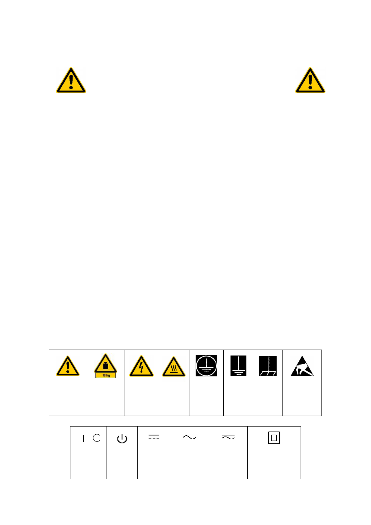
Symbols and safety labels
operating
instructions
Observe
indication for
units >18 kg
Supply
voltage
ON/OFF
Weight
indication
Standby
Danger of
electric
shock
Direct
current
(DC)
Warning!
Hot
surface
Alternating
current (AC)
PE
terminal
Ground
Direct/altern
ating current
(DC/AC)
double/reinforced
Ground
terminal
Device fully
protected by
insulation
Attention!
Electrostatic
sensitive
devices
1171.0000.52-01.00 Sheet 1
Page 10

Safety Instructions
Observing the safety instructions will help prevent personal injury or damage of any
kind caused by dangerous situations. Therefore, carefully read through and adhere to
the following safety instructions before putting the product into operation. It is also
absolutely essential to observe the additional safety instructions on personal safety
that appear in other parts of the documentation. In these safety instructions, the word
"product" refers to all merchandise sold and distributed by Rohde & Schwarz,
including instruments, systems and all accessories.
Tags and their meaning
DANGER This tag indicates a safety hazard with a high potential of
risk for the user that can result in death or serious injuries.
WARNING This tag indicates a safety hazard with a medium potential of
risk for the user that can result in death or serious injuries.
CAUTION This tag indicates a safety hazard with a low potential of risk
for the user that can result in slight or minor injuries.
ATTENTION This tag indicates the possibility of incorrect use that can
cause damage to the product.
NOTE This tag indicates a situation where the user should pay
special attention to operating the product but which does not
lead to damage.
Basic safety instructions
1. The product may be operated only
under the operating conditions and
in the positions specified by the
manufacturer. Its ventilation must
not be obstructed during operation.
Unless otherwise specified, the
following requirements apply to
Rohde & Schwarz products:
IP protection 2X, pollution severity
2, overvoltage category 2, use only
in enclosed spaces, max. operation
altitude max. 2000 m.
2. Applicable local or national safety
regulations and rules for the
prevention of accidents must be
observed in all work performed. The
product may be opened only by
authorized, specially trained
personnel.
Prior to performing any work on the
product or opening the product, the
instrument must be disconnected
from the supply network. Any
adjustments, replacements of parts,
maintenance or repair must be
carried out only by technical
personnel authorized by Rohde &
Schwarz. Only original parts may be
used for replacing parts relevant to
safety (e.g. power switches, power
transformers, fuses). A safety test
must always be performed after
parts relevant to safety have been
replaced (visual inspection, PE
conductor test, insulation resistance
measurement, leakage current
measurement, functional test).
1171.0000.52-01.00 Sheet 2
Page 11

Safety Instructions
3. As with all industrially manufactured
goods, the use of substances that
induce an allergic reaction
(allergens) such as aluminum
cannot be generally excluded. If you
develop an allergic reaction (such
as a skin rash, frequent sneezing,
red eyes or respiratory difficulties),
consult a physician immediately to
determine the cause.
4. Depending on the function, certain
products such as RF radio
equipment can produce an elevated
level of electromagnetic radiation.
Considering that unborn life requires
increased protection, pregnant
women should be protected by
appropriate measures. Persons with
pacemakers may also be
endangered by electromagnetic
radiation. The employer is required
to assess workplaces where there is
a special risk of exposure to
radiation and, if necessary, take
measures to avert the danger.
5. Operating the products requires
special training and intense
concentration. Disabled persons
should not use the products unless
it is made certain that their disability
has no adverse effects while they
are operating the products.
6. Prior to switching on the product, it
must be ensured that the nominal
voltage setting on the product
matches the nominal voltage of the
AC supply network. If a different
voltage is to be set, the power fuse
of the product may have to be
changed accordingly.
7. In the case of products of safety
class I with movable power cord and
connector, operation is permitted
only on sockets with earthing
contact and protective earth
connection.
8. Intentionally breaking the protective
earth connection either in the feed
line or in the product itself is not
permitted. Doing so can result in the
danger of an electric shock from the
product. If extension cords or
connector strips are implemented,
they must be checked on a regular
basis to ensure that they are safe to
use.
9. If the product has no power switch
for disconnection from the AC
supply, the plug of the connecting
cable is regarded as the
disconnecting device. In such
cases, it must be ensured that the
power plug is easily reachable and
accessible at all times (length of
connecting cable approx. 2 m).
Functional or electronic switches
are not suitable for providing
disconnection from the AC supply. If
products without power switches are
integrated in racks or systems, a
disconnecting device must be
provided at the system level.
10. Never use the product if the power
cable is damaged. By taking
appropriate safety measures and
carefully laying the power cable,
ensure that the cable cannot be
damaged and that no one can be
hurt by e.g. tripping over the cable
or suffering an electric shock.
11. The product may be operated only
from TN/TT supply networks fused
with max. 16 A.
12. Do not insert the plug into sockets
that are dusty or dirty. Insert the
plug firmly and all the way into the
socket. Otherwise this can result in
sparks, fire and/or injuries.
13. Do not overload any sockets,
extension cords or connector strips;
doing so can cause fire or electric
shocks.
1171.0000.52-01.00 Sheet 3
Page 12

Safety Instructions
14. For measurements in circuits with
voltages V
> 30 V, suitable
rms
measures (e.g. appropriate
measuring equipment, fusing,
current limiting, electrical
separation, insulation) should be
taken to avoid any hazards.
15. Ensure that the connections with
information technology equipment
comply with IEC950/EN60950.
16. Never remove the cover or part of
the housing while you are operating
the product. This will expose circuits
and components and can lead to
injuries, fire or damage to the
product.
17. If a product is to be permanently
installed, the connection between
the PE terminal on site and the
product's PE conductor must be
made first before any other
connection is made. The product
may be installed and connected
only by a skilled electrician.
18. For permanently installed
equipment without built-in fuses,
circuit breakers or similar protective
devices, the supply circuit must be
fused in such a way that suitable
protection is provided for users and
products.
19. Do not insert any objects into the
openings in the housing that are not
designed for this purpose. Never
pour any liquids onto or into the
housing. This can cause short
circuits inside the product and/or
electric shocks, fire or injuries.
20. Use suitable overvoltage protection
to ensure that no overvoltage (such
as that caused by a thunderstorm)
can reach the product. Otherwise
the operating personnel will be
endangered by electric shocks.
21. Rohde & Schwarz products are not
protected against penetration of
water, unless otherwise specified
(see also safety instruction 1.). If
this is not taken into account, there
exists the danger of electric shock
or damage to the product, which
can also lead to personal injury.
22. Never use the product under
conditions in which condensation
has formed or can form in or on the
product, e.g. if the product was
moved from a cold to a warm
environment.
23. Do not close any slots or openings
on the product, since they are
necessary for ventilation and
prevent the product from
overheating. Do not place the
product on soft surfaces such as
sofas or rugs or inside a closed
housing, unless this is well
ventilated.
24. Do not place the product on heatgenerating devices such as
radiators or fan heaters. The
temperature of the environment
must not exceed the maximum
temperature specified in the data
sheet.
25. Batteries and storage batteries must
not be exposed to high
temperatures or fire. Keep batteries
and storage batteries away from
children. If batteries or storage
batteries are improperly replaced,
this can cause an explosion
(warning: lithium cells). Replace the
battery or storage battery only with
the matching Rohde & Schwarz
type (see spare parts list). Batteries
and storage batteries are hazardous
waste. Dispose of them only in
specially marked containers.
Observe local regulations regarding
waste disposal. Do not short-circuit
batteries or storage batteries.
1171.0000.52-01.00 Sheet 4
Page 13

Safety Instructions
26. Please be aware that in the event of
a fire, toxic gases that may be
hazardous to your health may
escape from the product.
27. Please be aware of the weight of
the product. Be careful when
moving it; otherwise you may injure
your back or other parts of your
body.
28. Do not place the product on
surfaces, vehicles, cabinets or
tables that for reasons of weight or
stability are unsuitable for this
purpose. Always follow the
manufacturer's installation
instructions when installing the
product and fastening it to objects or
structures (e.g. walls and shelves).
29. If you use the product in a vehicle, it
is the sole responsibility of the driver
to drive the vehicle safely.
Adequately secure the product in
the vehicle to prevent injuries or
other damage in the event of an
accident. Never use the product in a
moving vehicle if doing so could
distract the driver of the vehicle. The
driver is always responsible for the
safety of the vehicle; the
manufacturer assumes no
responsibility for accidents or
collisions.
30. If a laser product (e.g. a CD/DVD
drive) is integrated in a Rohde &
Schwarz product, do not use any
other settings or functions than
those described in the documentation. Otherwise this may be
hazardous to your health, since the
laser beam can cause irreversible
damage to your eyes. Never try to
take such products apart, and never
look into the laser beam.
1171.0000.52-01.00 Sheet 5
Page 14

Informaciones de seguridad
Por favor lea imprescindiblemente antes de
la primera puesta en funcionamiento las
siguientes informaciones de seguridad
Informaciones de seguridad
Es el principio de Rohde&Schwarz de tener a sus productos siempre al día con los
estandards de seguridad y de ofrecer a sus clientes el máximo grado de seguridad.
Nuestros productos y todos los equipos adicionales son siempre fabricados y
examinados según las normas de seguridad vigentes. Nuestra sección de gestión de
la seguridad de calidad controla constantemente que sean cumplidas estas normas.
Este producto ha sido fabricado y examinado según el comprobante de conformidad
adjunto según las normas de la CE y ha salido de nuestra planta en estado impecable
según los estandards técnicos de seguridad. Para poder preservar este estado y
garantizar un funcionamiento libre de peligros, deberá el usuario atenerse a todas las
informaciones, informaciones de seguridad y notas de alerta. Rohde&Schwarz está
siempre a su disposición en caso de que tengan preguntas referentes a estas
informaciones de seguridad.
Además queda en la responsabilidad del usuario utilizar el producto en la forma
debida. Este producto solamente fue elaborado para ser utilizado en la indústria y el
laboratorio o para fines de campo y de ninguna manera deberá ser utilizado de modo
que alguna persona/cosa pueda ser dañada. El uso del producto fuera de sus fines
definidos o despreciando las informaciones de seguridad del fabricante queda en la
responsabilidad del usuario. El fabricante no se hace en ninguna forma responsable
de consecuencias a causa del maluso del producto.
Se parte del uso correcto del producto para los fines definidos si el producto es
utilizado dentro de las instrucciones del correspondiente manual del uso y dentro del
margen de rendimiento definido (ver hoja de datos, documentación, informaciones de
seguridad que siguen). El uso de los productos hace necesarios conocimientos
profundos y el conocimeinto del idioma inglés. Por eso se deberá tener en cuenta de
exclusivamente autorizar para el uso de los productos a personas péritas o
debidamente minuciosamente instruidas con los conocimientos citados. Si fuera
necesaria indumentaria de seguridad para el uso de productos de R&S, encontrará la
información debida en la documentación del producto en el capítulo correspondiente.
1171.0000.52-01.00 página 1
Page 15
Informaciones de seguridad
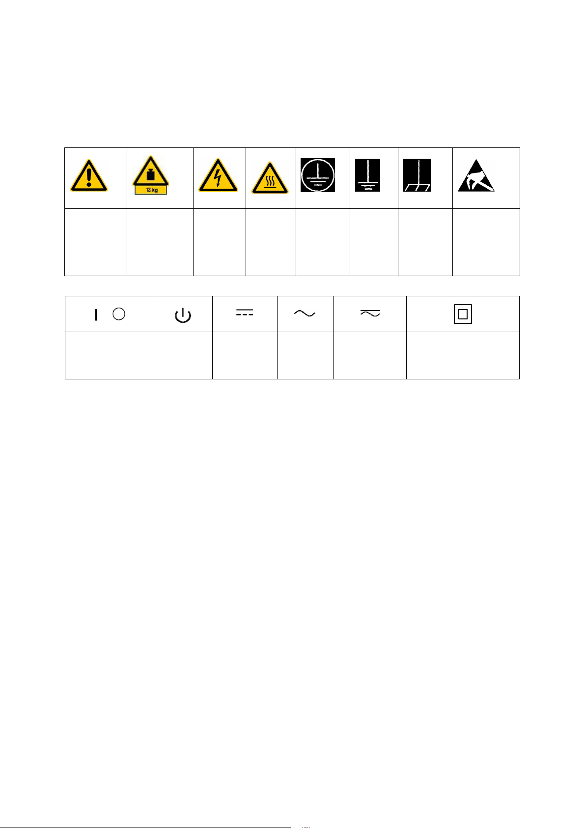
Símbolos y definiciones de seguridad
Ver manual
de
instrucciones
del uso
Informaciones
para
maquinaria
con uns peso
de > 18kg
Peligro de
golpe de
corriente
¡Cuidado!
Superficie
caliente
Conexión
a
conductor
protector
Conexión
a tierra
Conexión
a masa
conductora
¡Cuidado!
Elementos de
construción
con peligro de
carga
electroestática
potencia EN
MARCHA/PARADA
Indicación
Stand-by
Corriente
continua DC
Corriente
alterna AC
Corriente
continua/alterna
DC/AC
El aparato está protegido
en su totalidad por un
aislamiento de doble
refuerzo
Tener en cuenta las informaciones de seguridad sirve para tratar de evitar daños y
peligros de toda clase. Es necesario de que se lean las siguientes informaciones de
seguridad concienzudamente y se tengan en cuenta debidamente antes de la puesta
en funcionamiento del producto. También deberán ser tenidas en cuenta las
informaciones para la protección de personas que encontrarán en otro capítulo de
esta documentación y que también son obligatorias de seguir. En las informaciones
de seguridad actuales hemos juntado todos los objetos vendidos por Rohde&Schwarz
bajo la denominación de „producto“, entre ellos también aparatos, instalaciones así
como toda clase de accesorios.
Palabras de señal y su significado
PELIGRO Indica un punto de peligro con gran potencial de riesgo para el
ususario.Punto de peligro que puede llevar hasta la muerte o
graves heridas.
ADVERTENCIA Indica un punto de peligro con un protencial de riesgo mediano para
el usuario. Punto de peligro que puede llevar hasta la muerte o
graves heridas .
CUIDADO Indica un punto de peligro con un protencial de riesgo pequeño para
el usuario. Punto de peligro que puede llevar hasta heridas leves o
pequeñas
ATENCIÓN Indica la posibilidad de utilizar mal el producto y a consecuencia
dañarlo.
INFORMACIÓN Indica una situación en la que deberían seguirse las instrucciones
en el uso del producto, pero que no consecuentemente deben de
llevar a un daño del mismo.
1171.0000.52-01.00 página 2
Page 16

Informaciones de seguridad
Informaciones de seguridad elementales
1. El producto solamente debe ser
utilizado según lo indicado por el
fabricante referente a la situación
y posición de funcionamiento sin
que se obstruya la ventilación. Si
no se convino de otra manera, es
para los productos R&S válido lo
que sigue:
modo de protección IP 2X, grado
de suciedad 2, categoría de
sobrecarga eléctrica 2, utilizar
solamente en estancias interiores,
utilización hasta 2000 m sobre el
nivel del mar.
2. En todos los trabajos deberán ser
tenidas en cuenta las normas
locales de seguridad de trabajo y
de prevención de accidentes. El
producto solamente debe de ser
abierto por personal périto
autorizado. Antes de efectuar
trabajos en el producto o abrirlo
deberá este ser desconectado de
la corriente. El ajuste, el cambio
de partes, la manutención y la
reparación deberán ser solamente
efectuadas por electricistas
autorizados por R&S.Si se
reponen partes con importancia
para los aspectos de seguridad
(por ejemplo el enchufe, los
transformadores o los fusibles),
solamente podrán ser sustituidos
por partes originales.Despues de
cada recambio de partes
elementales para la seguridad
deberá ser efectuado un control
de seguridad (control a primera
vista, control de conductor
protector, medición de resistencia
de aislamiento, medición de
medición de la corriente
conductora, control de
funcionamiento).
3. Como en todo producto de
fabricación industrial no puede ser
excluido en general de que se
produzcan al usarlo elementos
que puedan generar alergias, los
llamados elementos alergénicos
(por ejemplo el aluminio). Si se
producieran en el trato con
productos R&S reacciones
alérgicas, como por ejemplo
urticaria, estornudos frecuentes,
irritación de la conjuntiva o
dificultades al respirar, se deberá
consultar inmediatamente a un
médico para averigurar los
motivos de estas reacciones.
4. Ciertos productos, como por
ejemplo las instalaciones de
radiación HF, pueden a causa de
su función natural, emitir una
radiación electromagnética
aumentada. En vista a la
protección de la vida en desarrollo
deberían ser protegidas personas
embarazadas debidamente.
También las personas con un
bypass pueden correr peligro a
causa de la radiación
electromagnética. El empresario
está comprometido a valorar y
señalar areas de trabajo en las
que se corra un riesgo de
exposición a radiaciones
aumentadas de riesgo aumentado
para evitar riesgos.
5. La utilización de los productos
requiere instrucciones especiales
y una alta concentracion en el
manejo. Personas minusválidas
solamente deberán utilizar estos
productos si está por seguro de
que a causa de su handicap no
podrá surgir ninguna restricción
en el manejo del producto.
1171.0000.52-01.00 página 3
Page 17

Informaciones de seguridad
6. Antes de la puesta en marcha del
producto se deberá tener por
seguro de que la tensión
preseleccionada en el producto
equivalga a la del la red de
distribución. Si es necesario
cambiar la preselección de la
tensión también se deberán en
caso dabo cambiar los fusibles
correspondientes del prodcuto.
7. Productos de la clase de
seguridad I con alimentación
móvil y enchufe individual de
producto solamente deberán ser
conectados para el
funcionamiento a tomas de
corriente de contacto de
seguridad y con conductor
protector conectado.
8. Queda prohibida toda clase de
interrupción intencionada del
conductor protector, tanto en la
toma de corriente como en el
mismo producto ya que puede
tener como consecuencia el
peligro de golpe de corriente por
el producto. Si se utilizaran cables
o enchufes de extensión se
deberá poner al seguro, que es
controlado su estado técnico de
seguridad.
instalaciones, se deberá instalar el
interruptor al nivel de la
instalación.
10. No utilice nunca el producto si
está dañado el cable eléctrico.
Asegure a través de las medidas
de protección y de instalación
adecuadas de que el cable de
eléctrico no pueda ser dañado o
de que nadie pueda ser dañado
por él, por ejemplo al tropezar o
por un golpe de corriente.
11. Solamente está permitido el
funcionamiento en redes de
distribución TN/TT aseguradas
con fusibles de como máximo 16
A.
12. Nunca conecte el enchufe en
tomas de corriente sucias o llenas
de polvo. Introduzca el enchufe
por completo y fuertemente en la
toma de corriente. Si no tiene en
consideración estas indicaciones
se arriesga a que se originen
chispas, fuego y/o heridas.
13. No sobrecargue las tomas de
corriente, los cables de extensión
o los enchufes de extensión ya
que esto pudiera causar fuego o
golpes de corriente.
9. Si el producto no está equipado
con un interruptor para
desconectarlo de la red, se
deberá considerar el enchufe del
cable de distribución como
interruptor. En estos casos deberá
asegurar de que el enchufe sea
de fácil acceso y nabejo (medida
del cable de distribución
aproximadamente 2 m). Los
interruptores de función o
electrónicos no son aptos para la
el corte de la red eléctrica. Si los
productos sin interruptor están
14. En las mediciones en circuitos de
corriente con una tensión de
entrada de Ueff > 30 V se deberá
tomar las precauciones debidas
para impedir cualquier peligro (por
ejemplo medios de medición
adecuados, seguros, limitación de
tensión, corte protector,
aislamiento etc.).
15. En caso de conexión con
aparatos de la técnica informática
se deberá tener en cuenta que
estos cumplan los requisitos de la
EC950/EN60950.
integrados en construciones o
1171.0000.52-01.00 página 4
Page 18

Informaciones de seguridad
16. Nunca abra la tapa o parte de ella
si el producto está en
funcionamiento. Esto pone a
descubierto los cables y
componentes eléctricos y puede
causar heridas, fuego o daños en
el producto.
17. Si un producto es instalado
fijamente en un lugar, se deberá
primero conectar el conductor
protector fijo con el conductor
protector del aparato antes de
hacer cualquier otra conexión. La
instalación y la conexión deberán
ser efecutadas por un electricista
especializado.
18. En caso de que los productos que
son instalados fijamente en un
lugar sean sin protector
implementado, autointerruptor o
similares objetos de protección,
deberá la toma de corriente estar
protegida de manera que los
productos o los usuarios estén
suficientemente protegidos.
también punto 1. Si no se tiene en
cuenta esto se arriesga el peligro
de golpe de corriente o de daños
en el producto lo cual también
puede llevar al peligro de
personas.
22. No utilice el producto bajo
condiciones en las que pueda
producirse y se hayan producido
líquidos de condensación en o
dentro del producto como por
ejemplo cuando se desplaza el
producto de un lugar frío a un
lugar caliente.
23. Por favor no cierre ninguna ranura
u orificio del producto, ya que
estas son necesarias para la
ventilación e impiden que el
producto se caliente demasiado.
No pongan el producto encima de
materiales blandos como por
ejemplo sofás o alfombras o
dentro de una caja cerrada, si
esta no está suficientemente
ventilada.
19. Por favor, no introduzca ningún
objeto que no esté destinado a
ello en los orificios de la caja del
aparato. No vierta nunca ninguna
clase de líquidos sobre o en la
caja. Esto puede producir corto
circuitos en el producto y/o puede
causar golpes de corriente, fuego
heridas.
20. Asegúrese con la protección
adecuada de que no pueda
originarse en el producto una
sobrecarga por ejemplo a causa
de una tormenta. Si no se verá el
personal que lo utilice expuesto al
peligro de un golpe de corriente.
21. Los productos R&S no están
protegidos contra el agua si no es
que exista otra indicación, ver
24. No ponga el producto sobre
aparatos que produzcan calor,
como por ejemplo radiadores o
calentadores. La temperatura
ambiental no debe superar la
temperatura máxima especificada
en la hoja de datos.
25. Baterías y acumuladores no
deben de ser expuestos a
temperaturas altas o al fuego.
Guardar baterías y acumuladores
fuera del alcance de los niños. Si
las baterías o los acumuladores
no son cambiados con la debida
atención existirá peligro de
explosión (atención celulas de
Litio). Cambiar las baterías o los
acumuladores solamente por los
del tipo R&S correspondiente (ver
lista de piezas de recambio).
1171.0000.52-01.00 página 5
Page 19

Informaciones de seguridad
Baterías y acumuladores son
deshechos problemáticos. Por
favor tirenlos en los recipientes
especiales para este fín. Por favor
tengan en cuenta las
prescripciones nacionales de cada
país referente al tratamiento de
deshechos. Nunca sometan a las
baterías o acumuladores a un
corto circuito.
26. Tengan en consideración de que
en caso de un incendio pueden
escaparse gases tóxicos del
producto, que pueden causar
daños a la salud.
27. Por favor tengan en cuenta el
peso del producto. Muevanlo
cuidadosamente ya que el peso
puede causar lesiones de la
espalda u otros daños físicos.
28. No sitúe el producto encima de
superficies, vehículos, estantes o
mesas, que por sus
características de peso o de
estabilidad no sean aptas para él.
Siga siempre las instrucciones de
instalación del fabricante cuando
instale y asegure el producto en
objetos o estructuras (por ejemplo
paredes y estantes).
29. Si llega a utilizar el producto
dentro de un vehículo, queda en
la responsabilidad absoluta del
conductor que conducir el
vehículo de manera segura.
Asegure el producto dentro del
vehículo debidamente para evitar
en caso de un accidente las
lesiones u otra clase de daños.
No utilice nunca el producto
dentro de un vehículo en
movimiento si esto pudiera
distraer al conductor. Siempre
queda en la responsabilidad
absoluta del conductor la
seguridad del vehículo y el
fabricante no asumirá ninguna
clase de responsabilidad por
accidentes o colisiones.
30. Dado el caso de que esté
integrado und producto de laser
en un producto R&S (por ejemplo
CD/DVD-ROM) no utilice otras
instalaciones o funciones que las
descritas en la documentación.
De otra manera pondrá en peligro
su salud, ya que el rayo laser
puede dañar irreversiblemente
sus ojos. Nunca trate de
descomponer estos productos.
Nunca mire dentro del rayo laser.
1171.0000.52-01.00 página 6
Page 20
Safety Instructions
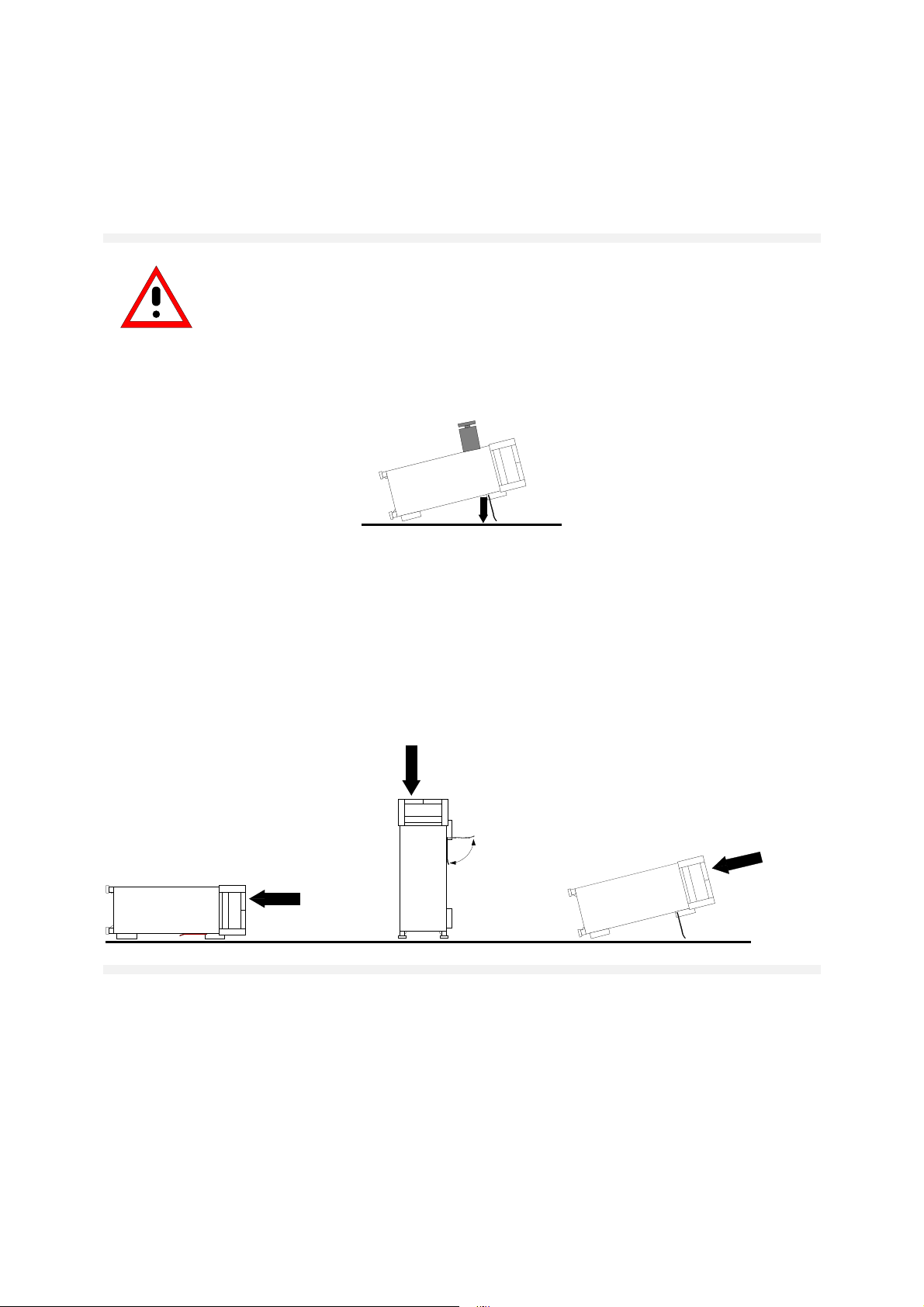
Safety instructions for instruments with fold-out feet
Warning!
The feet must be fully folded in or folded out. Only then can instrument
stability and reliable operation be ensured.
The total uniform load on the folded-out feet must not exceed 500 N
(combined weight of instrument and equipment stacked on top).
<500N
Additional equipment placed on the instrument must be protected
against slipping.
When the instrument is shifted with the feet folded out, the feet might
fold in. Thus, to avoid injury, the instrument must not be moved with
the feet folded out.
095.1000 Bl.15
Page 21

Quality Certificate
Dear Customer,
Thank you for purchasing a Rohde & Schwarz product. This product was created
using state-of-the-art production methods. It was developed, produced and tested in
accordance with our Quality Management System rules.
The Rohde & Schwarz Quality Management System has been certified in accordance
with ISO 9001, ISO 14001 and other standards.
095.1000 Bl.15
Page 22

Page 23

Telephone: +49 (0)180 512 42 42
Fax: +49 89 41 29 137 77
E-mail: CustomerSupport@rohde-schwarz.com
If you have any questions regarding this Rohde & Schwarz
instrument, please call our Support Center hotline at Rohde
& Schwarz Vertriebs-GmbH.
Our team will work with you to find a solution.
The hotline hours are 8:00 a.m. to 5:00 p.m. CET, Monday
through Friday.
If you wish to contact us outside normal business hours,
please leave a voice message or send us a fax or e-mail. We
will get in contact with you as soon as possible.
To keep your instrument up to date, please
subscribe for your personal newsletter at:
http://www.rohde-schwarz.com/www/response.nsf/newsletterpreselection.
You will receive information about the Rohde &
Schwarz products of your choice, firmware
expansions, new drivers and application
descriptions.
1007.8684.14-02.00
Page 24

Page 25

1 Front and Rear View
1164.4556.62 1.1 E-1
Page 26
Front view FSP
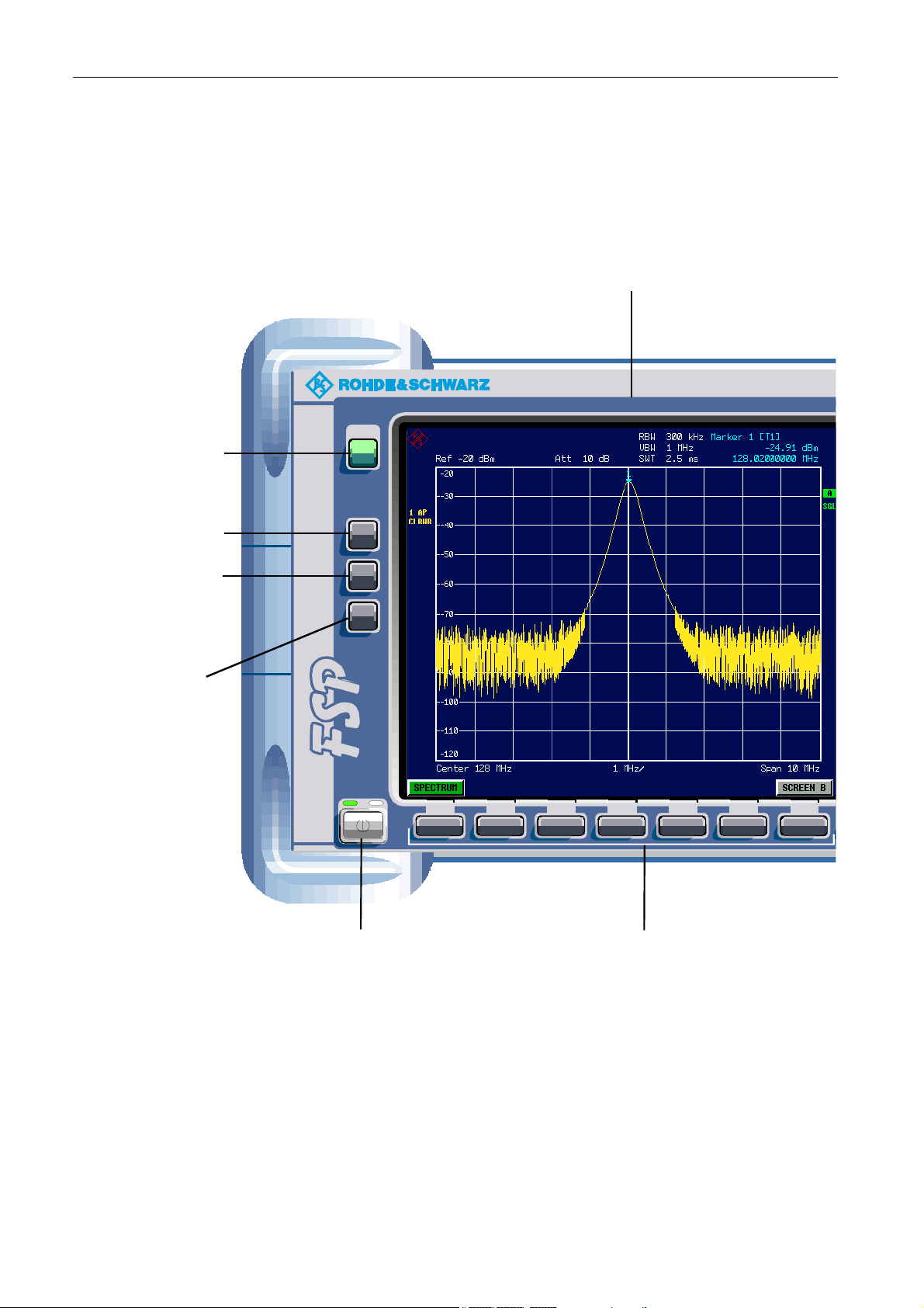
Front view
Screen
Preset key
Calibration
key (selfalignment)
Setup key
(default
settings)
HCopy key
(screen
printout)
PRESET
CAL
SETUP
HCOPY
SPECTRUM ANALYZER 9 kHz ... 30 GHzFSP
..
On/standby switch
Hotkeys
Fig. 1-1 Front view
1164.4556.62 1.2 E-1
Page 27
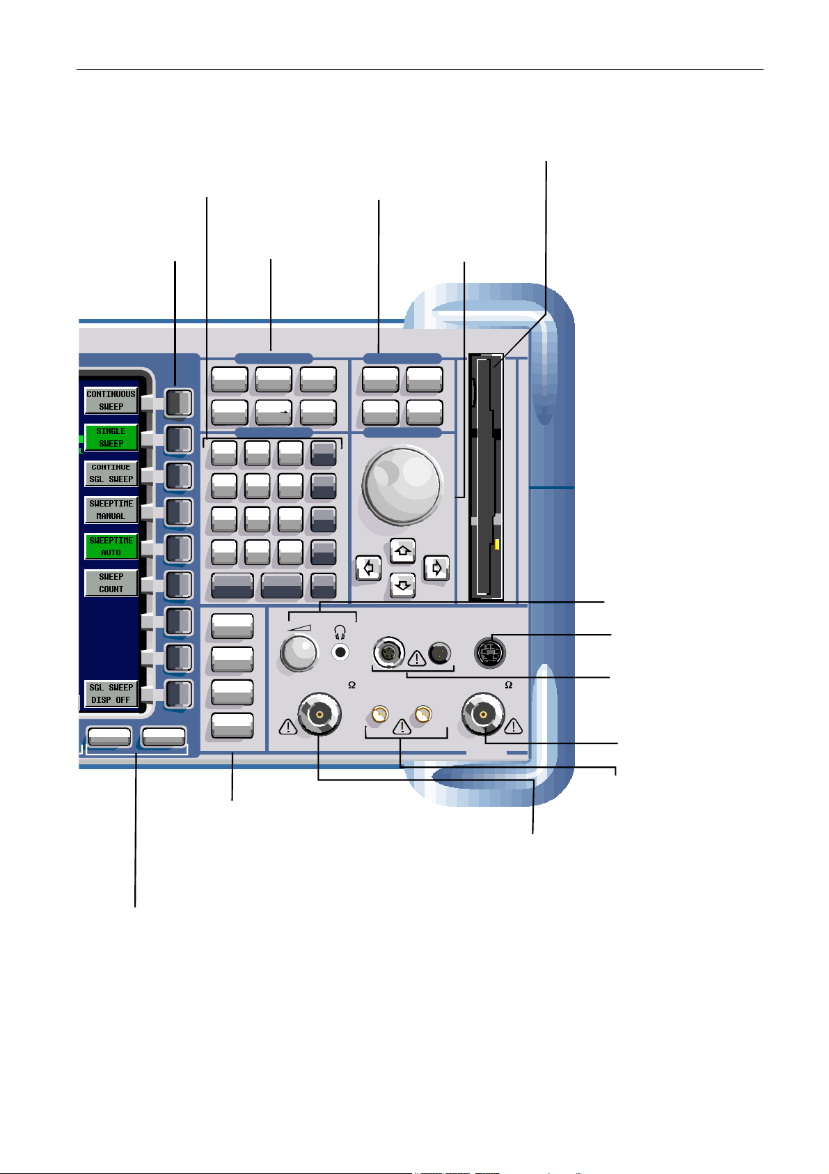
FSP Front view
r
Numeric keypad,
units and
entry keys
Function keys
for frequency,
Softkeys
level and markers
FREQ
MKR
7
4
123
measurement functions
CONTROL
SPAN
MKR
DATA
89
56
Function keys for
bandwidth, sweep,
trigger and
with Enter function
and cursor keys
SWEEP
AMPT
MKR
FCTN
GHz
-dBm
MHz
kHz
dBm
dB
s
V
ms
mV
µs
µV
BW SWEEP
MEAS
TRIG
VARIATION
3.5" disk drive;
1.44 MByte
Rotary knob
1164.4391.30
0
ESC
CANCEL
TRACE
LINES
DISP
PREV NEXT
FILE
TRACE Select and activate
traces and detectors
LINES Set limit lines
DISP Configure display
FILE Save and recall instrument data
Configuration of memory media and data
Previous key, next key
(softkey side menus)
.
ENTER
Hz
-
dB..
BACK
AF OUTPUT
GEN OUTPUT 50
MAX 0V DC
ns
nV
LO O UT / IF IN IF IN
KEYBOARDPROBE POWER
RF INPUT 50EXT MIXER
MAX +30 dBm / 0V DC
MADE IN GERMANY
AF output with
volume control
(option B3)
Keyboard
(PS/2-keyboard)
Probe Power c
(voltage supply for
measurement
accessories)
RF input (female
N connector, 50 Ω )
External mixer (LO output,
IF input, option B21)
Generator output
(tracking generator, female
Ω,
N connector, 50
option B9)
onnecto
1164.4556.62 1.3 E-1
Page 28

Front view FSP
Function Keys on the Front Panel
Funktion key Assigned functions
ON / STANDBY Switches the instrument on and off.
PRESET Resets the instrument to the default state.
Sets the center frequency as well as the start and stop frequencies for
FREQ
SPAN Sets the frequency span to be analyzed.
AMPT
MKR
the frequency band under consideration. This key is also used to set the
frequency offset and the signal track function.
Sets the reference level, the displayed dynamic range, the RF
attenuation and the unit for the level display. This key is also used to set
the level offset and the input impedance.
Sets and positions the absolute and relative measurement markers
(markers and delta markers). In addition, the following measurement
functions are assigned under this key:
• Frequency counter (SIGNAL COUNT)
• Fixed reference point for relative measurement markers
(REFERENCE FIXED)
• Enlargement of the measurement area (MARKER ZOOM)
MKR->
MKR FCTN
BW
SWEEP
Used for search functions of the measurement markers
(maximum/minimum of the trace).
Assigns the marker frequency to the center frequency, and the marker
level to the reference level.
Restricts the search area (SEARCH LIMITS) and characterizes the
maximum points and minimum points (PEAK EXCURSION).
Provides additional analysis functions of the measurement markers:
• Noise marker (NOISE MEAS)
• Phase noise (PHASE NOISE)
• n dB down function
• Peak list
• AM/FM audio demodulation (with option R&S FSP-B3)
Sets resolution bandwidth, video bandwidth and the two ratios
"resolution bandwidth/video bandwidth" and "span/resolution
bandwidth" in the case of automatic coupling.
Sets the sweep time and the number of measurement points.
Selects continuous measurement or single measurement.
1164.4556.62 1.4 E-1
Page 29

FSP Front view
Funktion key Assigned functions
Used to perform complex measurement functions:
• Measurement of time domain power (TIME DOM POWER)
• Measurement of channel and adjacent channel power (CHANNEL
POWER / ACP)
• Measurement of multicarrier adjacent channel power (MULT CARR
ACP)
MEAS
• Occupied bandwidth (OCCUPIED PWR BANDW)
• Signal statistics: amplitude probability distribution (APD) and
cumulative complementary distribution function (CCDF)
• Carrier to noise spacing (C/N, C/No)
• AM modulation depth (MODULATION DEPTH)
• Third-order intercept point (TOI)
TRIG
TRACE
LINES
DISP
FILE
CAL
SETUP
Sets trigger source, trigger threshold, trigger delay, and gate
configuration in the case of gated sweep.
Configures measured data acquisition (CLR/WRITE; AVERAGE,
MAXHOLD; MINHOLD, VIEW). Configures the analysis of the
measurement data (DETECTOR) and the mathematical linking of traces
(TRACE MATH).
Configures display lines and limit lines.
Configures the screen layout (one/two diagrams) and the diagram
contents. This key can also be used to configure the screen colors.
Provides the functions for storing/loading instrument settings and for
managing stored files.
Used to perform instrument self-calibration.
Used to set or display the following the default settings of the
instrument:
• Reference frequency, noise source, preamplifier, level correction
values (TRANSDUCER), date, time, IEC bus, RS-232-C interface,
LAN interface
• Firmware update and enabling of options
• Information about instrument configuration (SYSTEM INFO) incl.
firmware version, module data and system error messages
• Service support functions
HCOPY
Configures the screen printout, and selects and configures the printer.
1164.4556.62 1.5 E-1
Page 30
Rear view FSP
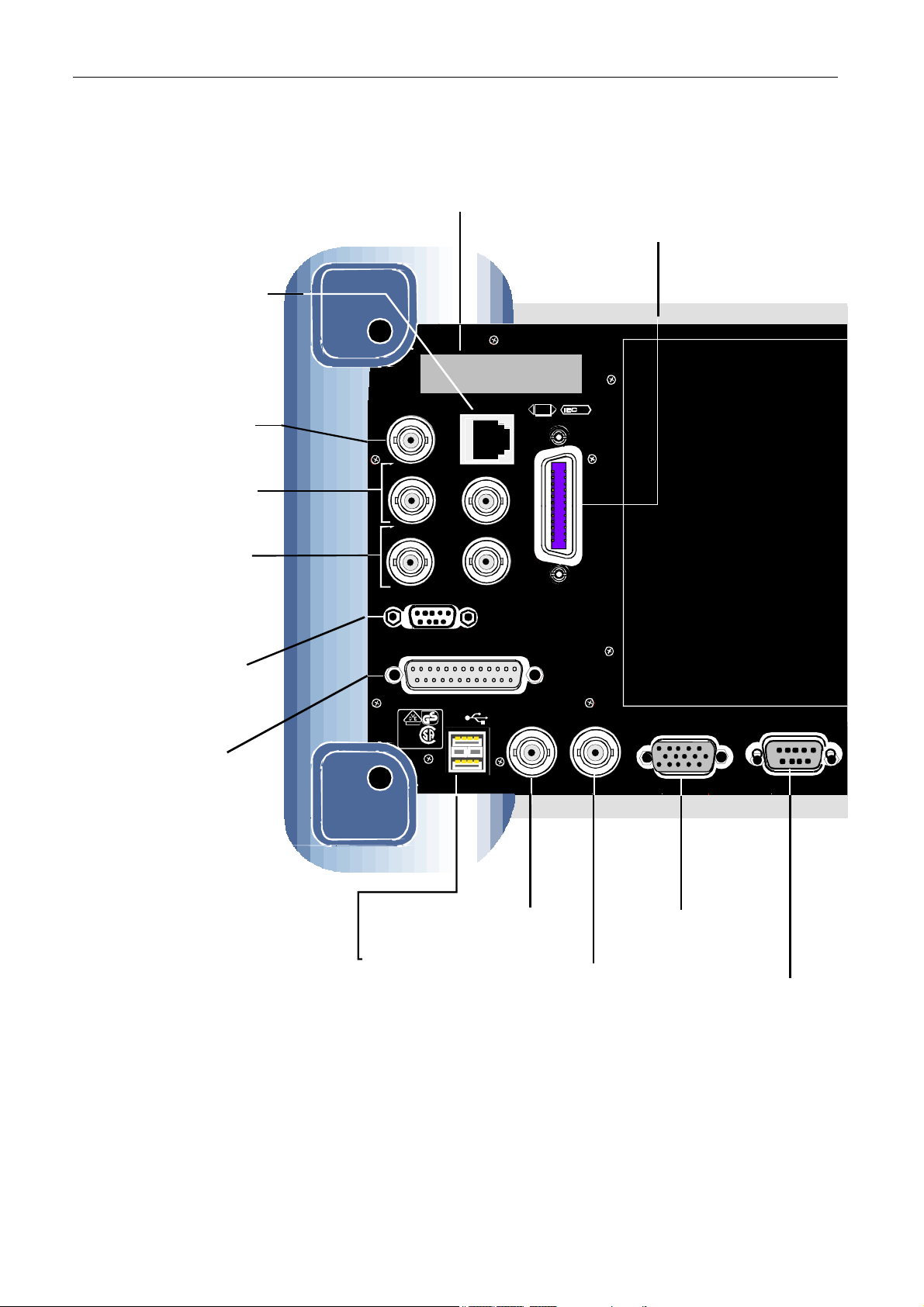
Rear View
LAN interface
10BaseT/100BaseT
(option B16)
CCVS IN/OUT
(switchable CCVS
input/output, option B6)
TG I IN / TG Q IN
( (I/Q inputs for tracking
generator, option B9)
REF IN
(input for external
reference (10 MHz))
REF OUT
(output for internal
reference (10 MHz))
AUX CONTROL
(control of external
generators, option B10)
Trigger port
(option B28)
Cover plate
20.4 - MHz OUT
TG I IN
REF IN REF OUT
AUX CONTROL
TRIGGER PORT
USB
LR 114 196
C®US
LAN
TG Q IN
I / Q DATA OUT
SCPI
EXT TRIG /
NOISE
GATE IN
IEC bus 2
(control of external
generators, option B10)
625
IEC 2
NOISE
SOURCE
MONITOR COM
Double USB interface
(USB 1.1)
Trigger/
gate interface
Noise Source
voltage supply
(28 V)
VGA interface
for external monitor
COM interface
(RS232-C)
Fig. 1-2 Rear view
1164.4556.62 1.6 E-1
Page 31

R&S FSP Rear view
AC power supply connector with on/off switch
100 - 24 0 VAC
3.1 - 1.3 A
LPT
LPT-
printer interface
625
SCPI
IEC bus for remote control
of instrument
1164.4556.62 1.7 E-1
Page 32

Spektrum Analyzers Connection R&S FSP
Spectrum Analyzers Connections
Front Panel of the Instrument
RF INPUT
The RF input is to be connected to the DUT via a cable equipped with a male N connector.
Be sure not to overload the input.
The maximum continuous power at the RF input is 30 dBm (1 W).
In the case of the FSP3 and FSP7, the RF input is AC-coupled. However, an
input DC voltage of 50 V must never be exceeded.
On the FSP13, FSP30 and FSP40, the RF input is DC-coupled. DC voltage
must not be applied at the input.
In both cases, noncompliance will destroy the input mixers.
Connections for External Mixers (EXT MIXER
External mixers can be connected at the LO OUT/IF IN and IF IN female connectors.
Two-port mixers can simply be connected to the LO OUT / IF IN female connector. In the
case of three-port mixers, the LO input of the mixer must be connected to the LO OUT / IF
IN female connector, and the IF output of the mixer to the IF IN female connector.
Connect the remaining mixer connector to the DUT.
The female connector is available only with the external mixer option (R&S FSP-B21).
Tracking Generator Output (GEN OUTPUT 50
The output of the tracking generator is to be connected to the DUT via a cable equipped
with a male N connector.
Note: In the case of DUTs with sensitive HF characteristics with regard to matching
(VSWR) at the input, insert a 20 dB attenuator between the DUT and the
tracking generator.
The female connector is available only with the tracking generator option (R&S FSP-B9).
))))
Ω)
Ω)
Ω)Ω)
AF OUTPUT
Headphones equipped with a miniature jack plug can be connected at the AF OUTPUT
female connector.
The internal impedance is 10 Ω. The output voltage can be set by using the volume control
to the left of the female connector. If a plug is connected, the internal loudspeaker will
automatically be switched off.
1164.4556.62 1.8 E-1
Page 33

R&S FSP Spectrum Analyzers Connections
The female connector and volume control are available only with the audio demodulator
option (FSP-B3).
PROBE POWER
To allow you to connect transducers from other manufacturers, the R&S FSP provides two
PROBE POWER supply connectors.
The left-hand connector supplies the ±10 V supply voltages and ground, making it suitable
for attaching R&S transducers.
The right-hand connector supplies the +15 V and –12.6 V supply voltages and ground. This
connector is suitable for supplying high-impedance probes from Agilent.
KEYBOARD
The front panel provides a PS/2 KEYBOARD female connector for connecting a keyboard.
Either keyboard PSP-Z1 (order no. 1091.4000.02, German) or PSP-Z2 (order no.
1091.4100.02, English) is recommended. These units contain not only a PC keyboard but
also a trackball for mouse control.
1164.4556.62 1.9E-1
Page 34

Spektrum Analyzers Connection R&S FSP
t
Rear Panel of the Instrument
AC Power Supply Connection and Main Power Switch
An AC power supply connector and main power switch are located in a unit on the rear
panel of the instrument.
Main power switch function:
Position I
Position O Switching the instrument off disconnects the entire instrument from the AC
Note: The main power switch also interrupts the power supply of the OCXO located
After being switched on, the instrument will be either in STANDBY mode or in
operation depending on the setting of the ON/STANDBY switch on the fron
panel of the instrument.
power supply.
in the instrument. When you switch the instrument back on, be sure to comply
with the extended warmup phase specified in the data sheet.
IEC Bus Interface
The instrument comes with an IEC bus interface in compliance with IEEE488. A controller for
remote control can be connected via this interface. Use a shielded cable to set up the connection.
Printer Interface (LPT)
The 25-pin female LPT connector on the rear panel of the R&S FSP is provided for
connecting a printer. The interface is compatible with the CENTRONICS interface.
RS-232-C Interface (COM)
The instrument comes with an RS-232-C interface. The interface can be manually activated
and configured for remote control by defining the parameters in the COM PORT table, which
is accessed from the SETUP-GENERAL SETUP menu.
R&S FSP Monitor Connection (MONITOR)
The 15-pin VGA monitor connection is used to display the screen contents on an external
screen. The procedure for putting the external monitor into operation is described in the
section "Connecting an External Monitor".
Noise Source Control (NOISE SOURCE)
The NOISE SOURCE female connector is used to switch an external noise source on and
off in order, for example, to measure the noise figure of DUTs.
Conventional noise sources require a voltage of +28 V in order to be switched on. They are
switched off at 0 V. The female connector supplies these switching voltages. The output supports
a maximum load of 100 mA.
1164.4556.62 1.10 E-1
Page 35

R&S FSP Spectrum Analyzers Connections
)
Input for External Trigger (EXT TRIG/GATE IN)
The EXT TRIG/GATE IN female connector is used to control the measurement by means of
an external signal.
The voltage levels are TTL levels (low <0.7 V; high >1.4 V). The typ. input impedance is 10 kΩ.
USB Interface (USB
Der R&S FSP provides a USB female connector for connecting two USB devices (USB 1.1).
Note: Passive USB connecting cables mu st not exceed 1 m in length.
Trigger Port (Option R&S FSP-B28)
The 25-pin trigger port female connector (option B28) provides a signal at pin 21 that signals
that the analyzer is ready to receive a trigger pulse. This signal takes into consideration the
analyzer's internal waiting and settling times.
In addition, the following pins are assigned: pin 13 +5 V, pin 25 +12 V, and GND at pin 12
and pin 24. The remaining pins are not assigned.
Pin 1 is located at the upper left of the female connector, and pin 25 at the lower right.
Aux Control (Option R&S FSP-B10)
If option B10 (external generator control) is built in, the R&S FSP provides a female
connector that allows measurement data acquisition to be synchronized with the output
signal of a Rohde & Schwarz generator.
Reference Input and Output (REF IN und REF OUT)
The REF IN female connector is used as an input for a 10 MHz reference signal. The
required input level is ≥0 dBm. The REF OUT female connector provides the internal 10
MHz reference signal with a 10 dBm output level for other devices.
The SETUP menu is used to select between the internal and external references.
If an external reference is used for operation, the external reference signal from REF IN is
looped through to REF OUT.
TG I / AM IN; TG Q / FM IN (Option R&S FSP-B9)
The two female connectors TG I /AM IN and TG Q /FM IN are used to modulate the
tracking generator (option R&S FSP-B9) by means of an external signal.
The input voltage range is ±0.5 V; the input impedance is 50 Ω.
1164.4556.62 1.11E-1
Page 36

Spektrum Analyzers Connection R&S FSP
20.4 MHz IF Output (20.4 MHz OUT)
The 20.4 MHz IF signal of the R&S FSP is provided at the 20.4 MHz OUT female BNC connector.
For resolution bandwidths between 100 kHz and 10 MHz, the bandwidth corresponds to the
selected bandwidth. For bandwidths ≤100 kHz, the bandwidth of the output is equal to 2.6 *
resolution bandwidth, where the minimum value is 2.6 kHz (non-FFT). In the analyzer mode, the
level at the IF output in the case of a signal at the reference level is 0 dBm if the resolution
bandwidth is ≥100 kHz; if the resolution bandwidth is <100 kHz, the level is -10 dBm (for mixer
levels ≥ -60 dBm).
Note: If the option R&S FSP-B6 is installed, this output is replaced by the CCVS IN/ OUT
female connector.
CCVS Output and Input (CCVS IN/OUT, Option R&S FSP-B6)
The CCVS IN/OUT female BNC connector is a switchable CCVS input/output. If TV
triggering is activated and triggering occurs in response to the internal demodulator signal
(CCVS INT), the demodulated TV signal is provided for operating an CCVS monitors. If
triggering occurs in response to an externally supplied CCVS signal (CCVS EXT), the
female connector serves as an input.
LAN Interface (Option B16)
The optional LAN interface can be used to connect to a local network. The assignment of
the RJ-45 connector supports twisted-pair category 5 UTP/STP cables in a star
configuration (UTP stands for “unshielded twisted pair”, and STP for “shielded twisted pair”).
Second IEC Bus Interface IEC2 (Option R&S FSP-B10)
When equipped with option B10 (external generator control), the instrument provides a
second IEC bus interface for using external generators.
Note: The R&S FSP remote control is not supported via the IEC2 interface.
1164.4556.62 1.12 E-1
Page 37

2 Putting into Operation
1164.4556.62 2.1 E-1
Page 38

Putting into Operation R&S FSP
Putting into Operation
This section describes how to put the instrument into operation.
Caution!
Before putting the instrument into operation, make sure that the following
requirements have been met:
• The air vents are not blocked.
• No signal voltage levels exceeding the permitted limits are present at the
inputs.
• The instrument's outputs are neither overloaded nor incorrectly connected.
Not complying with these requir ements can r esult in dam age to the i nstrum ent.
Unpacking the Instrument
Remove protective caps
Ø Remove the instrument from its packaging and check the
shipment against the packing list to ensure that all items are
included. Check the list of accessories for separate articles.
Ø Remove the two protective covers on the f ront and rear panels
of the R&S FSP and carefully check the instrument for any
damage.
Ø If you find any damage, immediately notify the shipping
company. In this case, do not discard the box and packaging
material.
Ø Retain the original packaging in the event that you need to
move or ship the R&S FSP in the future in order to avoid any
damage to the operating elements and connections. Rohde &
Schwarz will accept claims as covered in the warranty only if
the instrument is shipped with adequate packaging.
1164.4556.62 2.2 E-1
Page 39

R&S FSP P utti ng into Operation
Setting Up the Instrument
The instrument is intended for indoor use. Note the following in this regard:
• The ambient temperature must comply with the r ange speci fied in the data sheet.
• Air inflow and outflow via the air vents on the rear panel and through the lateral perforations
must not be obstructed. Clearance from walls must be at least 10 cm.
• The mounting surface must be even.
Note: To protect DUTs against electrostatic discharge in the event of contact, use
proper protective equipment:
Wrist strap with cord
Building g round
Ground conne ction
of operation al site
Heel strap
Floor mat
Installation in a 19" rack
The instrument can be installed in a 19" rack by using a rack adapter (see data sheet for
order number). The installation instructions are included with the adapter.
Caution!
When the instrument is installed in a rack, m ake sure that the vents for air
inflow on the side panel and the air outlets on the rear panel are not
obstructed.
1164.4556.62 2.3 E-1
Page 40

Putting into Operation R&S FSP
Connecting the Instrument to the AC Power Supply
The FSP is equipped with a mechanism for detecting AC power voltage and automatically sets
itself to use the available AC power voltage (range: AC voltage 100 V to 240 V; 50 Hz to 400
Hz). The AC power connector i s located on the rear panel of the instrument.
Ø Connect the R&S FSP to the AC power supply, using the
I
o
AC power
connector
power cable that is supplied.
Since the instrument is assembled in line with the
specifications for safety class EN61010, it may only be
connected to an outlet that has a ground contact.
Switching on the R&S FSP
Ø Press the power switch on the real panel to change it to position I.
Ø Press the ON/STANDBY switch on the front panel. The green LED will light up.
Caution!
Do not switch off the instrument while it is booting.
Switching it off prematurely can lead to serious data changes on
the instrument's hard disk
After being switched on, the R&S FSP displays the following information:
Rohde & Schwarz GmbH & Co. KG
Analyzer BIOS Vx.y
A selftest of the computer hardware will be carried out. Windows XP then starts, and
the measurement screen will automatically appear with the settings that were present
when the instrument was last switched off.
Note: If you want the instrument to automatically load different settings when it is
switched on, define the required configuration in the FILE - STARTUP
RECALL menu.
1164.4556.62 2.4 E-1
Page 41

R&S FSP P utti ng into Operation
Functional Test
Note: The functional test should only be performed when the operating temperature
is reached (approx. 15 minutes after the instrument is switched on).
Ø Call self- alignment with the CAL key, CAL TOTAL softkey. Once the system correction
values have been calculated successfully, the message "Calibration Passed" will appear.
Ø Start the selftest with the SETUP key, SERVICE – SELFTEST softkeys. Once the
instrument modules have been checked successfully, the message "Selftest Passed" will
appear.
Once both steps have been completed successfully, the instrument will be ready for
operation.
Note: The selftest does not need to be repeated every time the instrument is
switched on. It is necessary only when instrument malfunction is suspected.
Switching Off the R&S FSP
Ø Press the ON / STANDBY switch on the front panel.
The R&S FSP will store the current settings on the hard disk and then shut down the
software. Once the operation has been completed, the power supply unit will be switched
to STANDBY and the yellow LED will come on.
Warnin
In standby mode, the AC supply voltage is still present on the
instrument.
Ø To completely disconnect the instrument from the AC power supply, change the power
switch on the rear panel to position O.
Notes: 1. The main power switch on the rear panel also interrupts the power supply
of the OCXO inside the instrument. W hen you switch the instrument back
on, be sure to adhere to the extended warm-up phase.
2. If you switch off the instrument by using the power switch or by
disconnecting the power supply connector, it is not possible to save the
current instrument settings on the hard disk. In this case, the last settings
that were stored on the hard disk will be loaded when you switch the
instrument back on.
g:
1164.4556.62 2.5 E-1
Page 42

Connecting Peripheral Devices R&S FSP
Connecting Peripheral Devices
Connecting an External Keyboard
Caution:
Do not connect the keyboard unless the instrument is switched off
(STANDBY). Otherwise, proper functioning cannot be ensured due to
interactions with the firmware.
An external PC keyboard can be connected to the 6-pin PS/2 KEYBOARD connector on the
front panel of the R&S FSP or to the USB interface on the rear panel.
KEYBOARD
The keyboard simplifies instrument operation and the entry of comments, file names, etc.
Keyboards and mouse devices that conform to USB Standard 1.1 are suitable for
connection to the USB interface.
After being connected, the keyboard is automatically detected. The default keyboard
language setting is US English. Special settings such as refresh rate, etc, can be made in
the Windows XP KEYBOARD menu by selecting START - SETTINGS - CONTROL PANEL
- KEYBOARD.
USB
Connecting a Mouse
To simplify Windows XP operation, the R&S FSP allows you to connect a mouse to the
USB interface on the rear panel.
USB
Mouse devices from Microsoft and Logitech are supported.
Note: If you use a keyboard that contains a trackball for mouse operations,
connecting an external mouse in addition may lead to malfunctions.
1164.4556.62 2.6 E-1
Page 43

R&S FSP Connecting Peripheral Devices
After being connected, the mouse is automatically detected. Special settings such as
mouse cursor speed, etc, can be made in the Windows XP MOUSE menu by selecting
START - SETTINGS - CONTROL PANEL – MOUSE.
Connecting an External Monitor
Caution:
Do not connect a monitor unless the instrument is switched off (STANDBY).
Otherwise, you run the risk of damaging the monitor.
Do not change the screen driver ("Display Type") or the screen configuration,
as doing so can cause the instrument to malfunction.
You can connect an external monitor at the MONITOR connector on the instrument's rear
panel.
MONITOR
After you connect an external monitor, you must restart the instrument so that it will detect
the monitor. The measurement display will then appear on both the external screen and on
the instrument. No further settings are necessary.
Connecting a Printer
A printer can be connected during operation.
The R&S FSP allows you to create two different printer configurations for printing out a
hardcopy of the screen and you can toggle between them by pressing a button. The
DEVICES table in the HCOPY menu lists the available installed printers.
The interfaces for connecting a printer are located on the rear panel.
USB
LPT
1164.4556.62 2.7 E-1
Page 44

Connecting Peripheral Devices R&S FSP
Connecting USB Devices (e.g. a Pow er Meter)
The USB interface on the rear panel of the R&S FSP allows you to connect up to two USB
devices directly to the analyzer. This number can be increased as necessary by inserting
USB hubs.
Due to the large number of available USB devices, there is almost no limit to the
expansions that are possible with the R&S FSP. The following list shows various USB
devices that can be useful for the R&S FSP:
• Power Sensor R&S NRP-Z11 or R&S NRP-Z21
(requires Adapter Cable R&S NRP-Z4)
• Pendrive (memory stick) for easy transfer of data to/from a PC
(e.g. firmware updates)
• CD-ROM drives for easy installation of firmware applications
• PC keyboard for entering comments, file names, etc
• Mouse for easy operation of Windows dialog boxes
• Printer for printing out measurement results
• Modem for remote control of the R&S FSP over large distances
Installing USB devices is easy under Windows XP, because all USB devices are plug&play.
All USB devices can be connected to or disconnected from the R&S FSP during operation.
After a device is connected to the USB interface of the R&S FSP, Windows XP
automatically searches for a suitable device driver.
If Windows XP does not find a suitable driver, it will prompt you to specify a directory that
contains the driver software. If the driver software is on a CD, connect a USB CD-ROM
drive to the R&S FSP before proceeding.
When a USB device is subsequently disconnected from the R&S FSP, Windows XP
immediately detects the change in hardware configuration and deactivates the
corresponding driver.
1164.4556.62 2.8 E-1
Page 45

R&S FSP Connecting Peripheral Devices
Example:
Connect a pendrive (memory stick) to the R&S FSP:
1. When you connect the pendrive at the USB interface, Windows XP detects the new
hardware:
2. Windows XP installs the corresponding driver.
If installation is successful, Windows XP informs you that the device is ready to use:
3. The pendrive is made available as a new drive and is displayed under Windows Explorer:
The pendrive can be used like a normal drive to load or store data.
4. If you no longer need the pendrive or if you want to transfer files to another computer,
simply disconnect the pendrive. Windows XP will automatically deactivate the driver.
If the drive is still selected in Explorer, an error message will appear indicating that the
drive is no longer available.
1164.4556.62 2.9 E-1
Page 46

Connecting Peripheral Devices R&S FSP
Connecting External Generators
The option External Generator Control R&S FSP-B10 allows you to operate a number of
commercially available generators as a tracking generator on the R&S FSP. When suitable
generators are used, the R&S FSP thus allows scalar network analysis to be performed also
outside the freqency range of the internal tracking generator. Appendix C provides a list of
generators supported by the option R&S FSP-B10.
The following figure shows the test setup:
TTL (optional)
GPIB
AUX /
TRIGGER
BLANK
MARKER
IEC-BUS
GEN OUTPUT
Reference Frequency
REF
PRESET
CAL
SETUP
HCOPY
REF IN
SPECTRUM ANAL YZER 9kHz . . . 3GH z..FSP
.
IEC2
PREV
NEXT
FREQ
SPAN
MKR
MKR
789
45
12
0
.
ESC
ENTER
CANCEL
TRACE
LINES
DISP
FILE
6
3
-
GEN OUTPUT 50
MAX 0V DC
AUX
CONTROL
1093.4495. 03
AMPT
BW SWEEP
MKR
MEAS TRIG
FCTN
GHz
s
V
-dBm
ms
MHz
dBm
mV
µs
kHz
µV
dB
ns
Hz
nV
dB..
BACK
AF OUTPUT
KEYBOARDPROBE POWER
ΩΩΩΩ
RF INPUT
EXT MIXER
MAX +30 dBm / 50V DC
MADE IN GERMANY
RF INPUT
50
ΩΩΩΩ
DUT
The generator is controlled via the – optional – second IEC bus interface of the R&S FSP
(= IEC2, supplied together with the option). With some Rohde & Schwarz generators, it is
also controlled via the TTL synchronization interface that is contained in the AUX
CONTROL interface of the R&S FSP.
Notes: 1. Using the TTL interface allows you to attain significantly higher speeds
than possible with a pure IEC bus control, because the frequency
switching mechanism of the R&S FSP is directly coupled to the frequency
switching mechanism of the generator.
2. To increase measurement accuracy, use a shared reference frequency to
operate the R&S FSP and the generator. If no independent 10 MHz
reference frequency is available, connect the reference output of the
generator to the reference input of the R&S FSP and use SETUP –
REFERENCE EXT to configure the R&S FSP to implement the external
reference.
1164.4556.62 2.10 E-1
Page 47

R&S FSP Connecting Peripheral Devices
Connecting the R&S FSP to the Generator
To couple the frequency setting and level setting of the generator to the R&S FSP, set up
the following connections:
1. Connect the IEC bus (GPIB) interface of the generator to the IEC2 connector on the rear
panel of the analyzer.
2. (Optional:) Connect the TTL interface of the generator and the R&S FSP.
Ø Alternative 1 (R&S SMR, R&S SMU):
Connect the AUX CONTROL connector of the analyzer to the corresponding AUX
connector on the rear panel of the generator (the connection cable is supplied together
with the option R&S FSP-B10).
Ø Alternative 2 (R&S SME, R&S SMP, R&S SMIQ):
Connect the AUX CONTROL connector of the analyzer to the TRIGGER, MARKER
and BLANK connectors on the rear panel of the generator (the connection cable is
also supplied together with the option R&S FSP-B10). Note the labelling o n the
TRIGGER, MARKER and BLANK lines.
Ø Alternative 3 (R&S SML, R&S SMG/SMGU, R&S SMH/SMHU, R&S SMX/SMY,
generators from other manufacturers):
No TTL connection possible.
The generator type determines which one of the possible connections is suitable for the
generator. For more information, refer to the operating manual for the generator.
3. Connect the reference frequency output of the generator to the reference frequency input
(REF IN) of the analyzer.
Alternative:
Connect the reference frequency inputs of the two instruments to an external frequency
standard.
1164.4556.62 2.11 E-1
Page 48

Connecting Peripheral Devices R&S FSP
Configuring the Generator on the R&S FSP
To configure the generator, press the NETWORK hotkey located in the hotkey bar at the
lower edge of the screen.
Now complete the following steps:
1. Press the EXT SOURCE softkey. The submenu for configuring generators will open
2. Select and configure the generator:
Ø Press the SELECT GENERATOR softkey.
The table containing the generator settings will open. The selection bar will be located
in the row SRC 1 under the column TYPE.
Ø Press the ENTER key.
The list of available generators will open.
Ø Using the rotary knob, select the desired generator and activate ENTER by pressing
the rotary knob.
The generator list will close, and the selected generator will then appear in the
SELECT GENERATOR table. Simultaneously, the limits for frequency and output
power which you can set on the generator will appear in the F MIN, F MAX, P MIN and
P MAX fields.
Ø Using the key, move the selection bar to the IFC column and press the ENTER key.
The list of available control interfaces will appear.
Ø If the TTL interfaces from the R&S FSP and generator are connected, select TTL by
using the rotary knob and then activate it by pressing the rotary knob.
Ø If no TTL interface is provided or if the TTL interfaces are not connected, select GPIB
by using the rotary knob and then activate it by pressing the rotary knob.
Ø Using the key, move the selection bar to the GPIB ADDR column and press the
ENTER key.
The entry field for the IEC bus address of the generator will open.
Ø Enter the IEC bus address of the generator and confirm with ENTER.
The specified address will be added to the table.
3. Select the reference frequency for the generator:
Ø If you want to operate the generator using its internal reference, change the GEN REF
softkey to the state INT.
Ø If you want to operate the generator using an external reference, change the GEN
REF softkey to the state EXT.
This concludes the procedure for defining the default setting for the generator.
1164.4556.62 2.12 E-1
Page 49

R&S FSP Connecting Peripheral Devices
Note: A second generator configuration can be inserted in advance by repeating the
settings in the line SRC 2. This makes it easy to switch from one generator
type to another.
Activa ting the Generator Configuration and Setting the Output
Level
To select the active generator configuration, press the FREQUENCY SWEEP softkey. The
FREQUENCY SWEEP table will open, and the selection bar will be located under the
STATE column in the SRC 1 row.
Ø If you want to use the SRC 1 generator configuration, insert a checkmark in the field by
pressing the ENTER key.
Ø If you want to use the SRC 2 generator configuration, move the selection bar to the lower
line of the table by using the key. Then activate the generator configuration by
pressing the ENTER key and set the checkmark in line 2 under the STATE column.
Ø Using the key, move the selection bar to the POWER [dBm] column and press the
ENTER key.
Ø Enter the desired output power and confirm with the dBm key. The power you entered will
appear in the table.
Note: You can also change the output power of the generator by using the SOURCE
POWER key located in the NETWORK menu.
The remaining columns of the table are used to configure frequency-converting
measurements. For more information, refer to the section "Option External Generator
Control R&S FSP-B10" in the operating manual.
This concludes the procedure for configuring the generator.
1164.4556.62 2.13 E-1
Page 50

Connecting Peripheral Devices R&S FSP
Using an External Generator as a Tracking Generator
To activate the external generator as a tracking generator, do the following:
Ø Switch on the external generator.
Ø Press the NETWORK hotkey on the R&S FSP.
Ø Press the EXT SOURCE softkey.
Tracking generator operation using an external generator will be activated. The external
generator will switch to remote control operation and can be used like an internal tracking
generator. For more information about measurements with an external tracking generator,
refer to the section "Option External Generator Control R&S FSP-B10" in the operating
manual.
Test setup:
Ø Press the NETWORK hotkey on the R&S FSP.
Ø Press the EXT SOURCE softkey.
Ø Change the EXT SRC softkey to OFF by pressing it.
Note: When you switch off tracking generator operation using an external
generator, control on the IEC bus IEC2 is automatically released and the
generator is returned to LOCAL mode.
1164.4556.62 2.14 E-1
Page 51

R&S FSP Setup
R&S FSP Setup
Selecting the Frequency Reference
You can switch the reference signal for frequency processing of the R&S FSP between the
internal reference and an external reference signal at 10 MHz as follows:
Ø Press the SETUP key.
The SETUP menu will open.
Ø Press the REFERENCE INT/EXT softkey until it is in the desired state.
Note: If the r eference signal is m issi ng when switchover to the exter nal reference
occurs, the message "EXREF" will appear after a few moments, indicating
that synchronization has not taken place.
When switchover to an internal reference occurs, note that the external
reference signal is removed in or der to avoid any i nteractions wi th the internal
reference signal.
IEC bus command: ROSC:SOUR INT
Setting the Date and Time
Ø Press the SETUP key.
The SETUP menu will open.
Ø Press the GENERAL SETUP sof tkey.
The submenu with general settings will open.
The TIME+DATE softkey activates the TIME AND DATE table for entering the time and
date for the internal realtime clock.
Entering the time
Hours and minutes can be entered independently of each other in the entry field:
TIME
TIME
IEC bus command: SYST:TIME 12,30
1164.4556.62 2.15 E-1
12
30
:
Page 52

Setup R&S FSP
Entering the date
The day, month and year can be entered independently of each other in the entry field:
DATE
11
DATE
To select the month, use the units key to open a list containing the month names. You
can then select the month from the list.
IEC bus command: SYST:DATE 2002,03,11
Mar
2004
Setting the IEC Bus Interface
Ø Press the SETUP key.
The SETUP menu will open.
Ø Press the GENERAL SETUP sof tkey.
The submenu with general settings will open.
Ø Press the GPIB softkey.
The submenu for setting the parameters of the remote control interface will open.
IEC Bus Adress
Ø Press the GPIB ADDRESS softkey.
The entry field for the IEC bus address will open.
The setting range is from 0 to 30. The default address is 20 if SCPI is selected as the
IEC bus language or 18 if an 85xx emulation is selected.
IEC bus command: SYST:COMM:GPIB:ADDR 20
1164.4556.62 2.16 E-1
Page 53

R&S FSP Setup
IEC Bus Language
Ø Press the GPIB LANGUAGE softkey.
The list of available remote control languages will open.
The following languages are available:
• SCPI
• 8560E, 8561E, 8562E, 8563E, 8564E, 8565E
• 8566A, 8566B, 8568A, 8568B
• 8594E
Notes: If "856x" is selected, command recognition uses syntax rul es different from
those than when "SCPI" is selected. Correspondingly, correct detecti on of
SCPI commands is not ensured i n this m ode.
When the selection is changed, the following settings are changed:
SCPI:
• The instrument will perform a PRESET.
856xA/B, 856xE, 8594E:
• The instrument will perform a PRESET.
The following instrument settings will then be changed:
Model # of Trace
Points
8566A/B 1001 2 GHz 22 GHz 0 dBm DC (FSU)
8568A/B 1001 0 Hz 1.5 GHz 0 dBm AC
8560E 601 0 Hz 2.9 GHz 0 dBm AC
8561E 601 0 Hz 6.5 GHz 0 dBm AC
8562E 601 0 Hz 13.2 GHz 0 dBm AC
8563E 601 0 Hz 26.5 GHz 0 dBm AC
8564E 601 0 Hz 40 GHz 0 dBm AC
8565E 601 0 Hz 50 GHz 0 dBm AC
8594E 401 0 Hz 3 GHz 0 dBm AC
Start Freq. Stop Freq. Ref Level Input
AC (FSP)
Notes regarding the selection of 856x for the R&S FSP:
Coupling
• The # of trace points is not switched over until the state changes to REMOTE. In the
case of switchover to manual operation (LOCAL key) , the num ber of sweep points i s
always changed to 501.
• If necessary, the stop frequency specified i n the table is r estricted to the corr esponding
frequency range of the R&S FSP begrenz t.
IEC bus command: SYST:LANG "SCPI" | "8560E" |
"8561E" | "8562E" | "8563E" |
"8564E" | "8565E" | "8566A" |
"8566B" | "8568A" | "8568B" |
"8594E"
1164.4556.62 2.17 E-1
Page 54

Setup R&S FSP
ID Response String
Ø The ID STRING FACTORY softkey selects the default response to the command *IDN?.
IEC bus command: --
Ø The ID STRING USER softkey opens the editor for entering a user-defined response to
the command *IDN?. The max. length of the output string is 36 characters.
IEC bus command: --
Setting the Screen Colours
Ø Press the DISP key.
The DISPLAY menu will open.
Ø Press the CONFIG DISPLAY softkey.
The submenu for configuring the screen will open.
Ø The DEFAULT COLORS 1 and 2 softkeys set the default setting for brightness, tint and
colour saturation of all screen objects. The colour schemes are selected in such a
manner that all screen elements will be optimally visible regardless whether viewed from
above or below. In the instrument's default setting, DEFAULT COLORS 1 is active.
IEC bus command: DISP:CMAP:DEF1
DISP:CMAP:DEF2
The procedure for setting screen colours and brightness is as follows:
Ø Press the NEXT key.
The side menu for changing the screen colours will open.
The SELECT OBJECT softkey activates the selection of screen elements for which the
colour setting needs to be changed. Once this selection is made, the PREDEFINED
COLORS, BRIGHTNESS, TINT and SATURATION softkeys can be used to change the
overall colour or the brightness, tint and colour saturation of the selected element.
SELE CT DISPLAY O BJ ECT
Background
Grid
Function field + status field + data entry text
Function field LED on
Function field LED warn
Enhancement label text
Status field background
Trace 1
Trace 2
Trace 3
Marker
Lines
The BRIGHTNESS softkey activates entry of the brightness of the selected graphics
element.
The entry value is between 0% and 100%.
IEC bus command: DISP:CMAP5:HSL <hue>,<sat>,<lum>
1164.4556.62 2.18 E-1
Page 55

R&S FSP Setup
The TINT softkey activates entry of the tint for the selected graphics element. The
percent value that is entered refers to a continuous colour spectrum that ranges from red
(0%) to blue (100%).
IEC bus command: DISP:CMAP5:HSL <hue>,<sat>,<lum>
The SATURATION softkey activates entry of the colour saturati on of the selected element.
The entry value is between 0% and 100%.
IEC bus command: DISP:CMAP5:HSL <hue>,<sat>,<lum>
Ø The PREDEFINED COLORS softkey opens a list for selecting predefined colours for the
screen objects:
COLOR
BLACK
BLUE
BROWN
GREEN
CYAN
RED
MAGENTA
YELLOW
IEC bus command: DISP:CMAP1 ... 26:PDEF <color>
Automatically Switching Off the Internal Screen
The R&S FSP provides a feature for automatically switching off the screen after a userdefined period of time. The background lighting will be disabled if no entries are made from
the front panel after the selected response time (key, softkey or hardkey and rotary knob).
To activate automatic switch-off:
Ø Press the DISP key.
Ø Press the CONFIG DISPLAY softkey.
Ø Press the DISPLAY PWR SAVE softkey.
The softkey will have a colour background, indicating that the power save mode
is active. At the same time, the input window for the response time will open.
Ø Enter the desired response time in minutes and confirm the entry with the ENTER key.
The screen will be disabled (turn dark) after the selected period of time.
To deactivate automatic switch-off:
Ø Press the DISP key.
Ø Press the CONFIG DISPLAY softkey.
Ø Press the DISPLAY PWR SAVE softkey twice.
The colour background of the softkey will disappear.
The power save mode is now switched off.
1164.4556.62 2.19 E-1
Page 56

Setup R&S FSP
Selecting and Configuring Printers
Ø Press the HCOPY key.
The HARDCOPY menu will open.
Ø Press the DEVICE SETUP softkey.
The dialog box for selecting the file format and printer will open:
Ø You can select a connected printer (including a preconfigured network printer) by
positioning the selection bar on the Printer entry by turning the rotary knob and then
confirming the selection by pressing the rotary knob or the ENTER key.
After you confirm the selection, the entries Name, Print to File and Orientation will be
made available and can also be accessed with the rotary knob.
Ø To select the printer type, open the selection list by pressing the rotary knob or the
ENTER key after you access the Name field.
1164.4556.62 2.20 E-1
Page 57

R&S FSP Setup
From the selection list, you can now select the printer you want (in the example, this is
"Cannon Bubble-Jet BJC800 (A4)" ) by using the rotary knob again and then confirming
your selection with ENTER or by pressing the rotary knob. The selection list will then
disappear and the entry cursor will return to the Name field.
Ø You can also redirect the output to a file rather than to a printer. To do this, select the
field Print to File by using the rotary knob and then mark the appropriate selection box or
cancel the marking by pressing either the rotary knob or the ENTER key:
Ø You can select orientation for paper printout by using the Orientation field. To open the
selection list, press the rotary knob or ENTER:
From the selection list, you can now select the orientation you want ("Portrait" in the
preceding figure) by using the rotary knob again and then confirm with ENTER or by
pressing the rotary knob. The selection list will then close and the entry cursor will return
to the Orientation field.
You can now close the dialog box by pressing the ESC key or by selecting and
confirming the Close button.
1164.4556.62 2.21 E-1
Page 58

Setup R&S FSP
Selecting Alternative Printer Configurations
The analyzer can support two independent hardcopy settings. This allows you to quickly
switch between output to a file and a printer.
Ø To make a selection, use the DEVICE 1 / 2 softkey, which simultaneously shows the
associated setting when the "DEVICE SETUP" dialog box is open.
IEC bus command: --
Selecting Printer Colours
Ø The COLORS softkey opens the submenu for selecting the colours for the printout. To make
it easier for you to select colours, the selected hardcopy colour combination is display ed on
screen when you access the menu. When you exit the menu, the system switches back to
the previous colour combination.
Ø The COLOR ON OFF softkey switches from colour output to black-and-white printout. In
this case, all background colours will be printed out in white and all colour lines in black.
This allows you to improve contrast on the printout. The basic setting is COLOR ON.
IEC bus command: HCOP:DEV:COL ON
Ø The SCREEN COLORS softkey selects the current screen colours for the printout.
Note: The background will always be printed out in white and the grid in black.
IEC bus command: HCOP:CMAP:DEF1
Ø The OPTIMIZED COLORS softkey selects an optimized colour setting for the printout in
order to improve colour clarity on the printout.
With this selection, trace 1 will be printed out in blu e, trace 2 in black, trace 3 in green
and the markers in turquoise.
The other colours correspond to the screen colours of the DISP – CONFIG DISPLAY -
DEFAULT COLORS 1 softkey.
Note: The background will always be printed out in white and the grid in black.
IEC bus command: HCOP:CMAP:DEF2
Ø The USER DEFINED softkey opens a submenu for user-defined colour selection (see
the USER DEFINED COLORS submenu).
The procedure for making the settings is similar to that for setting the screen colours.
IEC bus command: HCOP:CMAP:DEF3
1164.4556.62 2.22 E-1
Page 59

R&S FSP Setup
Installing Plug&Play Printers
Plug&play printers can easily be installed under Windows XP:
After you connect and switch on a printer, Windows XP automatically detects the printer and
installs the associated driver, provided that the driver is contained in the Windows XP
installation.
If Windows XP does not find the printer driver, it will prompt you to enter a path for the
associated installation files. In addition to the preinstalled drivers, a number of additional
printer drivers are found in the D:\I386 directory.
Note: When you install printer drivers that are not preinstalled on the instrument, the
installation process will prompt you to sp ecify the path containing the new driver.
This can be a disk in drive A. Alternatively, the driver can also be loaded from a
memory stick or USB C D-R OM driv e (see the section "C onnecting USB Devi ces").
Installing Non-Plug&Play Printers
The procedure for installing non-plug&play printers is described in the appendix.
1164.4556.62 2.23 E-1
Page 60

Configuring the LAN Interface R&S FSP
Configuring the LAN Interface
(only with Option R&S FSP-B16)
The instrument can be connected to an Ethernet LAN (local area network) using the LAN
interface connector on the rear panel. This makes it possible to transfer data over the
network and to use network printers. In addition, the instrument can be remote-controlled
via the network. The network card can be operated with a 10 MHz Ethernet IEEE 802.3 or a
100 MHz Ethernet IEEE 802.3u interface.
Connecting the Instrument to the Network
Caution:
Before connecting the instrument to the network, consult your network
administrator, particularly in the case of large LAN installations. Connection
errors may affect the entire network.
Connect a conventional RJ-45 cable (not supplied) to the rear panel of the instrument and a
network hub of the required LAN segment. Since the RJ-45 involves star configuration
rather than bus cabling, no special measures need to be taken.
Setting up the connection does not cause any problems on the network. Likewise,
disconnecting the instrument from the network does not cause any problems as long as no
data traffic to and from the instrument is in progress.
Configuring the Network Card
Installation von Treibern
Under Windows XP, network card drivers do not need to be installed separately if the option
FSP-B16 has been factory-installed. All you need to do is connect the network cable to the
"LAN-Interface" connector on the instrument rear panel. Windows XP automatically detects
the network connection and activates the required drivers.
1164.4556.62 2.24 E-1
Page 61

R&S FSP Configuring the LAN Interface
Configuring the Interface
To configure the interface, do the following:
Ø Press the SETUP key.
The SETUP menu will open.
Ø Press the GENERAL SETUP softkey.
The submenu with all general settings will open.
Ø Press the CONFIGURE NETWORK softkey.
The dialog box with the network settings will open.
This softkey allows y ou to chang e the exi sting netw ork configur ation depending on the selection
of the affected registration cards (see section "Configuring Previously Installed Network
Protocols " in the section "Option FSP-B16 – LAN Interface").
IEC bus command: -
Note: Before you can configure network support, a PC keyboard with a trackball (or
an additional mouse rather than a trackball) must be connected.
1164.4556.62 2.25 E-1
Page 62

Configuring the LAN Interface R&S FSP
Configuring Existing Network Protocols (TCP/IP Protocol)
When you receive the instrument, the TCP/IP network protocol is already preinstalled with
IP address 10.0.0.10 and subnet mask 255.255.255.0 The steps that are necessary in order
to change this configuration and install additional network protocols are described in this
and the following sections.
Ø Open the Windows XP Start menu by pressing the Windows key or CTRL-ESC.
Ø Click Settings - Network Connections - Local Area Connection.
The Local Area Connection Status dialog box will open.
1164.4556.62 2.26 E-1
Page 63

R&S FSP Configuring the LAN Interface
Note: Windows XP automatically appends numbers to the name Local Area
Connection Status (e.g. Local Area Connection Status 8) if the configuration is
set up using the New Connection wizard. These numbers are not important in
the following configuration steps and are therefore omitted.
Ø Click the Properties button.
The window with the available network protocols will open.
Ø Click the network protocol you want (TCP/IP in the example).
Ø Click the Properties button.
The dialog box with the settings for the selected network protocol will open.
If the IP address will automatically be requested from a DHCP server, select Obtain an IP
address automatically.
Note: Your network administrator will know whether your network has a DHCP
server.
Ø Click OK. Windows will store the configuration.
Ø If you want to enter a predefined IP address (because, for example, the network does not
have a DHCP server), select Use the following IP address.
1164.4556.62 2.27 E-1
Page 64

Configuring the LAN Interface R&S FSP
Ø Select IP address and enter the IP address.
Ø Then select Subnet mask and enter the required mask.
Note: Your network administrator will know which IP addresses and subnet masks
are suitable for your network.
Ø Click OK.
Windows will check the entered settings for correctness and then store the configuration.
If you have entered an invalid IP address or subnet mask, an error message will appear that
also asks you whether you want to enter a different address or mask:
Ø Click Yes.
The dialog box for entering the TCP/IP parameters will open again.
If all settings are correct, you will be prompted to restart the instrument if required by the
changes.
1164.4556.62 2.28 E-1
Page 65

R&S FSP Configuring the LAN Interface
Ø Click Yes.
Windows will restart the system.
Installing Additional Network Protocols and Services
The procedure for installing additional network protocols and services is provided in the
appendix.
1164.4556.62 2.29 E-1
Page 66

Operating System Properties R&S FSP
Operating System Properties
Properties Specific to Windows XP
The instrument contains the Windows XP Embedded operating system. To ensure that the
instrument software functions properly, certain rules must be adhered to when using the
operating system.
Caution:
The drivers and programs used in the instrument under Windows XP have
been adapted to the instrument. To avoid impairments to instrument
function, use only the settings described in the operating manual and this
manual.
Only update software approved by Rohde & Schwarz may be used to
modify existing instrument software.
Likewise, only programs approved by Rohde & Schwarz for use on the
instrument may be run on the instrument.
Login
Windows XP requires that users identify themselves by entering a user name and password
in a login window. The instrument already includes a factory-installed autologin function, i.e.
login is carred out automatically in the background. The predefined user name is
"instrument" and the password is also "instrument" (lowercase).
Administrator ID
The ID used by the instrument to perform autologin has administrator rights.
1164.4556.62 2.30 E-1
Page 67

R&S FSP Operating System Properties
Windows-XP Service Packs
The Windows XP Embedded operating system on the instrument is supplied with preinstalled XP Embedded service packs that are necessary and suitable for operating the
instrument.
Caution:
To prevent malfunctions, only service packs approved by Rohde &
Schwarz may be loaded on the instrument. Malfunctions may necessitate
instrument repair in worst cases.
You should be particularly careful not to use service packs from Windows
XP Home Edition or Professional Edition because they are not compatible
with Windows XP Embedded.
Opening the Windows XP Start Menu
You can open the Windows XP Start menu by pressing the Windows key ( ) or the key
combination <CTRL> <ESC>. From the start menu, you can navigate to the submenus by
using the mouse or the cursor keys. To return to the measurement screen, activate the
"R&S Analyzer Interface" button in the Start bar.
Windows XP Software Approved for the Instrument
The driver software that is used and the system settings of W indows XP have been finetuned to support the measurement functions of the R&S FSP. Thus, flawless instrument
function is ensured only if software and hardware approved or offered by Rohde & Schwarz
are used.
Using other software or hardware may cause the functions of the R&S FSP to perform
improperly or fail.
The following program packages have been successfully tested for compatibility with the
measurement instrument software:
• R&S FS-K3 – Software for measuring noise factor and gain
• R&S FS-K4 – Software for measuring phase noise
• R&S Power Viewer (virtual power meter for displaying results of the Power Sensor R&S
NRP-Z11 and Z21)
• Windows XP Remote Desktop
• FileShredder – For reliable deletion of files on the hard disk
• Symantec Norton AntiVirus – Virus-protection software
• McAfee Virusscan
1164.4556.62 2.31 E-1
Page 68

Page 69

3 Firmware-Update and Installation of
Firmware Options
1164.4556.62 3.1 E-1
Page 70

Firmware Update R&S FSP
Firmware Update
You can install a new firmware version by using the built-in disk drive, a memory stick, a USB
CD-ROM or a LAN. The firmware update kit contains several disks whose contents must be
stored in separate directories (D isk1 to D isk< n> ) when a memory stick or LAN is used. Start the
installation program from the SETUP menu.
Ø Press the SETUP key.
The SETUP menu will open.
Ø Press the NEXT key.
The side menu will open.
Ø Press the FIRMWARE UPDATE softkey.
The subdirectory for installing or deinstalling new firmware versions will open.
Press the UPDATE PATH softkey (only in the case of firmware updates via a memory
stick, CD-ROM or LAN). The entry field for the path with the set of update disks will open.
Enter the drive name and directory and confirm with <ENTER>.
Example: The disk contents are stored on a memory stick in the "Update" directory and
in the "Disk1" to "Disk<n>" subdirectories. After you insert the memory stick, it
will be detected as drive "E:".
In this case, the required path specification is "E:\UPDATE".
Ø To start the installation program, press the FIRMWARE UPDATE softkey in the
submenu. The installation program will then guide you through the remainder of the
update procedure.
IEC bus command: "SYST:FIRM:UPD 'E:\UPDATE'"
Ø To restore the prev ious firmw are v ersion, pr ess the RESTORE FIRM WARE softkey.
IEC bus command: --
1164.4556.62 3.2 E-1
Page 71

R&S FSP Aktivating of Firmware Options
Activating Firmware Options
Firmware options are enabled by entering license keys via the following operating
sequence:
Ø Press the SETUP key.
The SETUP menu will open.
Ø Press the GENERAL SETUP sof tkey.
Ø Press the OPTIONS softkey.
The OPTIONS menu will open. Options already available are listed in a table that is
displayed when the submenu is opened.
Ø Press the INSTALL OPTION softkey.
The field for entering the license key for the firmware option now appears.
After you enter a valid license key, OPTION KEY OK will appear in the message line and
the option will be entered in the FIRMWARE OPTIONS table.
If you enter an invalid license key, the message OPTION KEY INVALID will appear in the
message line.
Ø The REMOVE OPTION softkey deletes all existing firmware options. To prevent unintentional
deletion, the system asks you to confirm that you really want to perform this operation.
1164.4556.62 3.3 E-1
Page 72

Page 73

4 Brief Introduction
1164.4556.62 4.1 E-1
Page 74

Diagram Layout R&S FSP
Diagram Layout
Status
information
Trace-info
Logo
title /date
This is a screen title (20 chars)
26.Jun 99 22:57
-10 Offset 10 dB
UNCAL
1 AM
1 Pk
VIEW
VIEW
1-2
1-2
2 SA
2 SA
VIEW
VIEW
3 AV
3 MI
VIEW
VIEW
LOUNL
Hardware-
Ref -10 dBm ATT 10 dB
LIMIT CHECK FAIL
-20
-30
-40
-50
-60
TRG -60dB m
LINE Test FAIL
settings M
RBW 300 kHz Marker 1 [T1]
UBW 1 MHz -19.62 dBm
SWT 2,5 ms 130.00000000 MHz
arker/Deltamarker
Delta 2 [T1]
-42.80 dB
1.00000000 MHz
Delta 3 [T1]
-42.84 dB
-1.00000000 MHz
Delta 4 [T1]
-61.49 dB
-2.56000000 MHz
Test
-90
Level axis labelling
-100
-110
Center 130 MHz 1 MHz/ Span 10 MHz
Frequency
axis
labelling
Fig. 4-1 Screen layout of the R&S FSP during analyzer operation
Dirty flag
A
SGL
GAT
Enhancement
TRG
labels
LVL
FRQ
75ΩΩΩΩ
1164.4556.62 4.2 E-1
Page 75

R&S FSP Diagr am Layout
Displays in the Diagram Area
Hardware settings
Ref
Offset
Att
EATT
RBW
VBW
SWT
Marker /
Delta
Display of the reference level.
Display of the reference level offset.
Display of the RF attenuation that has been set.
Display of the set RF attenuation when an electronic attenuator is used
(only with option Electronic Attenuator, B25).
Display of the resolution bandwidth that has been set.
If the bandwidth does not correspond to the value for automatic coupling,
a green asterisk "*" will appear in front of the field.
Display of the video bandwidth that has been set.
If the bandwidth does not correspond to the value for automatic coupling,
a green asterisk "*" will appear in front of the field.
Display of the sweep time that has been set (SWEEP TIME).
If the sweep time does not correspond to the value for automatic coupling,
an asterisk "*" will appear in front of the field. The color of the asterisk will
turn to red if the sweep time is set below the value for automatic coupling.
In this case, the sweep time must be increased.
Contains the x and y axis positions of the last marker or delta marker that
was set as well as its index. The value in the square brackets after the
index indicates the trace to which the marker is assigned as well as the
active measurement function.
LIMIT
CHECK
The measurement functions of the markers are indicated with the following
abbreviations:
• FXD Reference fixed marker active
• PHN Phase noise measurement active
• CNT Frequency counter active
• TRK Signal track active
• NOI Noise measurement active
• MOD Measurement of the AM modulation depth active
• TOI TOI measurement active
Display of the results of the limit check.
1164.4556.62 4.3 E-1
Page 76

Diagram Layout R&S FSP
Status displays
The status displays on the left side of the diagram indicate any irregularities (e.g. UNCA L).
UNCAL
OVLD
IFOVL
LOUNL
EXREF
OVEN
"UNCAL" indicates that one of the following conditions is present:
• Correction data has been switched off (menu CAL, CAL CORR OFF).
Þ Switch on the correction CAL CORR ON or PRESET.
• No valid correction values are available. This occurs, for example, if a firmware
update is performed followed by a cold start of the instrument.
Þ Record the correction data.
"OVLD" indicates an overload of the input mixer.
Þ Increase the RF attenuation.
"IFOVL“ indicates an overload of the IF signal path after the input mixer.
Þ Increase the reference level.
"LOUNL" indicates that an error was detected in the instrument's frequency
processing hardware.
“EXREF” is displayed if the instrument was set to an external reference but no
signal was detected on the reference input.
"OVEN“ indicates that the OCXO reference frequency (option B4) has not yet
reached its operating temperature. The message usually disappears a few
minutes after power-on.
1164.4556.62 4.4 E-1
Page 77

R&S FSP Diagr am Layout
Trace information
Trace #
1 PK *
CLRWR
1-2
Trace
Difference
Detector
auto /
manual
Trace
Mode
Trace # = Trace number (1 to 3)
Detector = Selected detector:
AP: AUTOPEAK detector
PK: MAX PEAK detector
MI: MIN PEAK detector
SA: SAMPLE detector
AV: AVERAGE detector
RM: RMS detector
QP: QUASIPEAK detector
auto /
manual = The selected detector does not
match the one for automatic
coupling.
Trace
Mode = Display of the sweep mode:
CLRWR: CLEAR/WRITE
MAXH: MAX HOLD
MINH: MIN HOLD
AVG: AVERAGE
VIEW: VIEW
TraceMathematik = Indicates that the trace
difference function is activated.
1 - 2 Trace 1 - Trace 2
1 - 3: Trace 1 - Trace 3
1164.4556.62 4.5 E-1
Page 78

Diagram Layout R&S FSP
Enhancement labels:
The enhancement labels on the right-hand side of the measurement diagram indicate that
the user chose instrument settings that affect the measurement results even though this is
not immediately apparent from the display of the measured values.
*
A / B
SGL
GAT
TRG
LVL
FRQ
The current instrument setting does not match the one during which the displayed
traces were recorded. This occurs in the following cases:
• The instrument setting is changed while a measurement is in progress.
• The instrument setting is changed in the SINGLE SWEEP mode after the end of
the sweep, and a new sweep is not started.
• The instrument setting is changed after a trace has been set to VIEW.
The display remains on screen until the user eliminates the cause. In some cases,
this involves starting a new sweep (SINGLE SWEEP mode) or switching the
affected trace to BLANK.
Designation for screen A / B. If screen A / B is activated for entering measurement
parameters, the label background will be in color.
The sweep is set to SINGLE SWEEP.
The frequency sweep is controlled via the EXT TRIG/GATE connector.
Instrument triggering is not free running (≠ FREE RUN).
A level offset ≠ 0 dB is set.
A frequency offset ≠ 0 Hz is set.
TDF
PRN
75 ΩΩΩΩ The input impedance of the instrument is set to 75 Ω.
EXT
PA
A TRANSDUCER FACTOR is activated.
Printer output is active.
The instrument is configured for operation with an external reference.
The RF PREAMPLIFIER is switched on (opti on B25).
1164.4556.62 4.6 E-1
Page 79

R&S FSP Setting Parameters
Setting Parameters
The Keypad
The keypad is used to enter numeric parameters. It contains the
s
89
7
4
56
12
0
.
ESC
CANCEL
ENTER
OK
GHz
V
-dBm
MHz
ms
mV
mV
dBm
kHz
3
dB
following keys:
• Numeric keys 0...9
µs
• Decimal point
µV
Inserts a decimal point "." at the cursor position.
Hz
dB..
BACK
ns
nV
• Sign key
Changes the sign of a numeric parameter.
-
In the case of an alphanumeric parameter, inserts a "-" at the
cursor position.
• Unit keys (GHz/-dBm MHz/dBm, kHz/ dB and Hz/dB)
These keys add the selected unit to the entered numeric value
and complete the entry.
In the case of level entries (e.g. in dB) or dimensionless values,
all units have the value "1" as mulitplying factor. Thus, they have
the same function as an ENTER key. The same is true for an
alphanumeric entry.
In addition, the unit keys open and close selection fields in tables
(subtables).
• BACK key
– If a numeric entry has already been started, this key deletes
the character to the left of the cursor.
– If an entry has been completed or not yet started, this key
toggles between the currently and previously valid value
(UNDO function).
• ESC/CANCEL key
– Closes the entry field if an entry has been started or has not
yet been made. The original value is retained.
– Closes the entry field if an entry has been completed.
– Closes the "System Messages" window.
• ENTER key
– Concludes the entry of dimensionless entries. The new value
is accepted.
Note: With frequency entries, the ENTER key corresponds to the
Hz key. With time data, it corresponds to the µs(kHz) key.
1164.4556.62 4.7 E-1
Page 80

Setting Parameters R&S FSP
Y
A
T
r
The Rotary Knob and Cursor Keys
The rotary knob and cursor keys are located next to the keypad.
The rotary knob has several functions:
• Increments (clockwise direction) or decrements (counterclockwise
direction) the instrument parameter at a defined step width in the case
of a numeric entry.
• Shifts the selection bar horizontally or vertically within tables as long
as an entry field is not open. The cursor keys are used to change the
direction of motion (horizontal/vertical).
• Selects the individual letters when the alphanumeric editor is used.
• Shifts markers, limit lines, etc on the screen.
• When it is pressed, it concludes an entry.
Within a table, the cursor keys move the selection bar to the desired
position.
Within the alphanumeric editor, the or. cursor keys move the
cursor to the desired position.
The or. cursor keys do the following:
• Increase or decrease the instrument parameter in the case of numeric
entries.
• Switch between the editing line and the character selection in the case
of alphanumeric entries.
Editing Numeric Parameters
Numeric values are always entered in a data entry field that automatically appears after the
parameter is selected.
itle line with paramete
START FREQUENC
10.2457535 GHz
ST
RT FREQUENCY OUT OF RANGE
designation
Editing line with parameter
value and unit
Status and error messages
The title line shows the name of the instrument parameter that was selected. The entry is
performed in the editing line. After the entry field is opened, it will contain the currently valid
parameter value and its unit. The optional third and fourth lines show status and error
messages which always refer to the current entry.
1164.4556.62 4.8 E-1
Page 81

R&S FSP Setting Parameters
V
W
m
Editing Alphanumeric Parameters
If an external keyboard is not available, the character selection field is automatically opened
for entering alphanumeric parameters. Two models of the alphanumeric editor are available.
Alphanumeric Editor Type 1:
CALIBRATION FILE
C:\MEASDATA\STANDARD.CAL
Entry (editing) line
Message line
BCDEFGHIJKLMNOPQRSTU
A
abcdefghijkl
nopqrstuvwxyzäöüß,;<>|@µ²³^°1234567890
XYZÄÖÜ!?"$%/(){[]}\+*#~'-_=.:
Character selection
field
The or cursor keys switch between the editing line and the character selection field.
Entering the text
Ø Select the parameter.
Data entry is automatically activated after the data entry field is opened. The cursor is
now located at the start of the previous entry in the editing line.
Ø Using the cursor key, place the cursor in the character selection field.
The cursor now marks the first letter of the editor.
Ø Using the or cursor keys or the rotary knob, place the cursor on the character that
you want to enter in the editing line.
Ø Press either the ENTER key or the rotary knob.
The character will be added to the editing line.
Correcting the entry
Ø Using the
cursor key, place the cursor in the editing line.
Ø Using the and cursor keys or the rotary knob, place the cursor after the character
you want to delete.
Ø Press the BACK key.
The entry to the left of the cursor will be deleted.
Correcting the entry
Ø Using the
key, place the cursor in the editing line.
Ø Press one of the unit keys or the rotary knob.
The data entry field will close, and the new entry will be accepted by the instrument.
Cancelling the entry
Ø Press the ESC key.
The data entry field will close, and the previous entry will be retained.
1164.4556.62 4.9 E-1
Page 82

Setting Parameters R&S FSP
Alphanumeric Editor Type 2:
The entry area consists of two parts:
• The editing line
• The character selection field
The or cursor keys switch between the editing line and the character selection field.
Entering the text
Ø Select a parameter.
Data entry is automatically activated after the data entry field is opened. In tables, the
character selection field is accessed by using the cursor key.
The cursor is now located at the start of the existing entry in the editing line.
Ø Using the cursor key, place the cursor in the character selection field.
The cursor now marks the first character of the editor.
Ø Using the or cursor keys or the rotary knob, place the cursor on the character that
you want to enter in the editing line.
Ø Press the ENTER key or the rotary knob.
The character will be added to the editing line.
Correcting the entry ( alternative 1)
Ø Using the rotary knob, go to the << character in the character selection field.
Ø By pressing the rotary knob on << and >>, place the cursor after the character you want
to delete.
Ø Using the rotary knob, select the BACK field and press the rotary knob.
The entry to the left of the cursor in the editing line will be deleted.
Correcting the entry (alternative 2)
Ø Using the cursor key, place the cursor in the editing line.
Ø Using the and cursor keys or the rotary knob, place the cursor after the character
you want to delete.
Ø Press the BACK key.
The entry to the left of the cursor will be deleted.
Completing the entry (alternative 1)
Ø Using the rotary knob, select the EXIT field and then press the rotar y knob.
The data entry field will close, and the new entry will be accepted by the instrument.
1164.4556.62 4.10 E-1
Page 83

R&S FSP Setting Parameters
Completing the entry (alternative 2)
Ø Using the cursor key, place the cursor by the editing line.
Ø Press one of the unit keys or the rotary knob.
The data entry field will close, and the new entry will be accepted by the instrument.
Cancelling the entry
Ø Press the ESC key.
The data entry field will close, and the previous entry will be retained.
1164.4556.62 4.11 E-1
Page 84

Page 85

5 Introduction
This section provides a brief introduction on operating the Spectrum Analyzer R&S FSP. A
more detailed discussion of the basic operating steps, e.g. selecting menus and setting
parameters, plus measurement examples are provided in chapters 2, 3 and 4 of the
operating manual.
1164.4556.62 5.1 E-1
Page 86

Measuring a Sinusoidal Signal R&S FSP
Measuring a Sinusoidal Signal
One of the most common measurement tasks that can be handled by using a spectrum
analyzer is determining the level and frequency of a signal. When measuring an unknown
signal, you can usually start with the PRESET setting.
Note: If levels higher than +30 dBm (=1 W) are expected or are possible, a power
attenuator must be inserted before the RF input of the analyzer. If this is not
done, signal levels exceeding 30 dBm can damage the RF attenuator or the
input mixer. The total power of all signals that are present must be taken into
account.
In the following examples, a signal generator is used as a signal source.
Test setup:
Connect the RF output of the signal generator to the RF input of R&S FSP.
Settings on the signal generator:
Frequency: 128 MHz
Level: -30 dBm
Measuring the Level and Frequency with Markers
The level and frequency of a sinusoidal signal can be measured easily by using the marker
function. The R&S FSP always displays its amplitude and frequency at the marker position.
The frequency measurement uncertainty is determined by the reference frequency of the
R&S FSP, the resolution of the marker frequency display and the resolution of the screen.
Procedure
1. Reset the instrument.
Ø Press the PRESET key
2. Connect the signal to be measured to the RF INPUT analyzer input on the
instrument front panel.
3. Set the center frequency to 128 MHz.
Ø Press the FREQ key.
The entry field for the center frequency appears on screen.
Ø Using the numeric keypad in the input field, enter 128 and confirm the entry with the
MHz key.
1164.4556.62 5.2 E-1
Page 87

R&S FSP Measuring a Sinusoidal Signal
4. Reduce the frequency span (SPAN) to 1 MHz.
Ø Press the SPAN key.
Ø Using the numeric keypad in the input field, enter 1 and confirm the entry with the MHz
key.
Note: When the frequency span is defined, the resolution bandwidth (RES BW), the
video bandwidth (VIDEO BW) and the sweep time (SWEEP TIME) are
automatically reset, because these functions are l inked in the PRESET setti ng.
5. Measure the level and frequency using the marker and read the results from the
screen.
Ø Press the MKR key.
The marker is activated and automatically jumps to the maximum of the trace.
Note: When a marker is initially acti vated, it autom atical ly perfor m s the PEAK SEARCH
function (as shown in the example).
If a marker was already active, you have to press the PEAK key in the M KR->
menu in order to set the currently acti ve mar ker to the m axim um of the displ ayed
signal.
The level and frequency values measured by the marker are displayed in the marker
field at the top edge of the screen. They can be taken as the measurement result.
The field header indicates the number of the marker (MARKER 1) and the trace on
which the marker is located ([T1] = Trace 1).
Increasing the Frequency Resolution
The frequency resolution of the marker is predefined by the the pixel resolution of the trace.
A trace uses 501 pixels, i.e. when the frequency span is 1 MHz, each pixel corresponds to a
span of approx. 2 kHz. This corresponds to a maximum uncertainty of 1 kHz.
You can increase the pixel resolution of the trace by reducing the frequency span.
1. Reduce the frequency span (SPAN) to 10 kHz.
Ø Press the SPAN key.
Ø Using the numeric keypad, enter 10 in the entry field and confirm the entry with the
kHz key.
The generator signal is measured using a span of 10 kHz. The pixel resolution of the
trace is now approx. 20 Hz (10 kHz span / 501 pixels) , i.e. the precision of the marker
frequency display increases to approx. ±10 Hz.
1164.4556.62 5.3 E-1
Page 88

Measuring a Sinusoidal Signal R&S FSP
Setting the Reference Level
With spectrum analyzers, the reference level (REF LEVEL) is the level at the upper limit of
the diagram. To achieve the widest dynamic range possible for a spectrum measurement,
use the entire level span of the spectrum analyzer. In other words, the highest level that
occurs in the spectrum must be located at the top edge of the diagram (=reference level) or
immediately below it.
Note: If the reference level that is selected is less than the highest signal that occurs
in the spectrum, the signal path in the R&S FSP will be overloaded.
In this case, the message IFOVL will appear on the left-hand edge of the diagram.
In the preset setting, the value of the reference level is -20 dBm. If the input signal is -30 dBm,
the reference level can be reduced by 20 dB w ithout causing the sig nal path to be ov erloaded.
1. Reduce the reference level by 10 dB.
Ø Press the AMPT key.
The AMPT menu will appear in the softkey bar. The REF LEVEL softkey will be
highlighted in red to indicate that it is activated for data entry. The entry field for the
reference level is also opened and displays a value of -20 dBm.
Ø Using the numeric keypad, enter 30 and confirm the entry with the -dBm key.
The reference level is now set to -30 dBm. The maximum of the trace is near the
maximum of the measurement diagram. However, the increase in the displayed noise is
not substantial. Thus, the distance between the signal maximum and the noise display
(=dynamic range) has increased.
2. Setting the marker level equal to the reference level
The marker can also be used to shift the maximum value of the trace directly to the top
edge of the diagram. If the marker is located at the maximum level of the trace (as in this
example), the reference level can be moved to the marker level as follows:
Ø Press the MKRÞ key.
Ø Press the REF LVL = MKR LVL softkey.
The reference level will be set equal to the measured level where the marker is
located.
Thus, setting the reference level is reduced to two keystrokes.
1164.4556.62 5.4 E-1
Page 89

R&S FSP Measuring a Sinusoidal Signal
Measuring the Signal Frequency using the Frequen cy Counter
The built-in frequency counter makes it possible to measure the frequency more precisely
than measuring it with the marker. The frequency sweep is stopped at the marker, and the
R&S FSP measures the frequency of the signal at the marker position.
In the following example, the frequency of the generator at 128 MHz is shown by using the
marker.
1. Set the spectrum analyzer to the default state.
Ø Press the PRESET key.
The R&S FSP is in the default state.
2. Set the center frequency and the span.
Ø Press the FREQ key and enter 128 MHz.
The center frequency of the R&S FSP is set to 128 MHz.
Ø Press the SPAN softkey and enter 1 MHz.
The frequency span of the R&S FSPs set to 1 MHz.
3. Activate the marker
Ø Press the MKR key.
The marker is activated and set to the signal maximum. The level and the frequency of
the marker are displayed in the marker information field.
4. Activate the frequency counter.
Ø Press the SIGNAL COUNT softkey in the marker menu.
The result of frequency counting is displayed in the selected resolution (1 kHz in the
default state) in the marker field at the top edge of the screen.
5. Set the resolution of the frequency counter to 1 Hz.
Ø Go to the right-hand side menu of the marker menu (press the NEXT key.).
Ø Press the CNT RESOL 1 Hz softkey.
1164.4556.62 5.5 E-1
Page 90

Measuring a Sinusoidal Signal R&S FSP
Fig. 5-1 Measurement of the frequency with the frequency counter
Note: Obtaining a correct result when measur ing the frequency wi th the internal
frequency counter requires that an RF sinusoidal si gnal or a spectral line be
present. The marker must be l ocated mor e than 25 dB above the noise l evel
to ensure that the specified measurement accur acy is adhered to.
Tip: For bandwidths between 300 kHz and 10 MHz, the time for measuring the
frequency is inversely proportional to the selected resolution, i.e. a
resolution of 1 Hz requires a gate time of 1 second for the counter.
For digital bandwidths of less than 300 kHz, the time for measuring the
frequency is always approx. 30 ms and is not affected by the resolution
that is set.
Thus, when measuring the frequency of a sinusoidal carrier that has high
resolution, set the resolution bandwidth to 100 kHz or less.
1164.4556.62 5.6 E-1
Page 91

R&S FSP Measuring Harmonics of Sinusoidal Signals
Measuring Harmonics of Sinusoidal Signals
Measuring the harmonics of a signal is a very common task that can be optimally perf ormed
by using a spectrum analyzer.
In the following example, the generator signal with 128 MHz and -30 dBm is used again.
Measuring the Suppression of the First and Second Harmonic of an Input Signal
1. Spektrumanalysator in den Grundzustand setzen.
Ø Press the PRESET key.
The R&S FSP is now in the default state.
2. Set the start frequency to 100 MHz and the stop frequency to 400 MHz.
Ø Press the FREQ key.
Ø Press the START softkey drücken and enter 100 MHz eingeben.
Ø Press the STOP softkey and enter 400 MHz.
The R&S FSP displays the fundamental and the first and second harmonics of the
input signal.
3. For maximum sensitivity, set the RF attenuation to 0 dB.
Ø Press the AMPT key.
Ø Press the RF ATTEN MANUAL softkey and enter 0 dB.
4. To average (suppress) the noise, reduce the video bandwidth.
Ø Press the BW key.
Ø Press the COUPLING RATIO softkey.
Ø Using the cursor keys, select RBW/VBW NOISE [10].
The video bandwidth (VBW) will now always be set to less than the resolution bandwidth
(RBW) by a factor of 10.
5. Activate the marker.
Ø Press the MKR key.
Marker 1 will be activated and positioned to the signal maximum (fundamental at 128 MHz).
The level and frequency of the marker will be displayed in the marker information field.
1164.4556.62 5.7 E-1
Page 92

Measuring Harmonics of Sinusoidal Signals R&S FSP
6. Activate the delta marker and measure the harmonic suppression.
Ø Press the MARKER 2 softkey in the marker menu.
Marker 2 will be activated as the delta marker (Delta 2 [T1]). It automatically appears
on the largest harmonic of the signal. The frequency offset and level offset from
marker 1 are displayed in the marker field at the top edge of the screen.
Ø Press the MARKER 3 softkey in the marker menu.
Marker 3 is activated as the delta mar ker (Del ta 3 [T1]). It automatically appears on the nex t
largest harmonic of the signal. The frequency offset and level offset from marker 1 on the
fundamental are displayed in the marker field at the top edg e of the screen. (see Fig. 5- 3)
Fig. 5-3 Measuring the harmonic suppression of the internal reference generator.
Markers delta 2 [T1] and delta 3 [T1] show the offset of the first and second
harmonics from the fundamental.
Reducing Noise
The spectrum analyzer offers three means of effectively differentiating the harmonics of a
signal from the noise:
• Reducing the video bandwidth
• Averaging the trace
• Reducing the resolution bandwidth
Reducing the video bandwidth and averaging the traces cause the noise from the analyzer
or the DUT to be reduced, depending on which component is larger. Both averaging
methods reduce the measurement uncertainty particularly in the case of small signal-tonoise ratios, because the measurement signal is also separated from the noise.
1164.4556.62 5.8 E-1
Page 93

R&S FSP Measuring Harmonics of Sinusoidal Signals
1. Reducing the noise by reducing the video bandwidth.
Ø Press the BW key.
Ø Press the VIDEO BW MANUA L softkey.
Ø Using the rotary knob (turning it counterclockwise), reduce the video bandwidth to 10
kHz (for example), or enter 10 kHz.
This clearly smooths the noise, and the sweep time will increase to 25 ms. In other
words, the measurement will clearly take more time. The video bandwidth that is
shown in the display is marked with an asterisk (*VBW) to indicate that it is no longer
coupled to the resolution bandwidth (see Fig. 5-4).
Fig. 5-4 Suppression of noise during harmonics measurement by reducing video
bandwidth
2. Recouple the video bandwidth to the resolution bandwidth.
Ø Press the BW key.
3. Reduce the noise by averaging the curve.
Ø Press the TRACE key.
Ø Press the AVERAGE softkey.
The noise component of the trace will be smoothed by averaging 10 successive
traces.
4. Switch off trace averaging.
Ø Press the CLEAR/WRITE softkey.
1164.4556.62 5.9 E-1
Page 94

Measuring Harmonics of Sinusoidal Signals R&S FSP
5. Reduce the noise by reducing the measurement bandwidth.
The noise is reduced in proportion to the bandwi dth by r educi ng the r esoluti on bandwidth,
i.e. reducing the resolution bandw idth by a factor of 10 also reduces the noise by a factor
of 10 (which corresponds to 10 dB). The amplitude of sinusoidal sig nal s is not affected by
reducing the resolution bandwi dth.
6. Set the resolution bandwidth to 10 kHz.
Ø Press the BW key.
Ø Press the RES BW MANUAL softkey and enter 10 kHz.
The noise decreases by approx. 25 dB with respect to the previous setting. Since the
video bandwidth is coupled to the resolution bandwidth, it is reduced to 1 kHz in
proportion to the resolution bandwidth. This causes the sweep time to increase to 60
seconds.
7. Reset the resolution bandwidth (couple it to the span)
Ø Press the RES BW AUTO softkey.
1164.4556.62 5.10 E-1
Page 95

R&S FSP Measuring Signal Spectra with Multiple Signals
Measuring Signal Spectra with Multiple Signals
Separating Signals by Selecting the Resolution Bandwidth
A basic feature of a spectrum analyzer is being able to separate the spectral components of
a mixture of signals. The resolution at which the individual components can be separated is
determined by the resolution bandwidth. Selecting a resolution bandwidth that is too large
may make it impossible to distinguish between spectral components, i.e they will appear as
a single component.
An RF sinusoidal signal will be shown on the spectrum analyzer screen by means of the
passband characteristic of the resolution filter (RBW) that has been set. Its specified
bandwidth is the 3 dB bandwidth of the filter.
Two signals with the same amplitiude can be resolved if the resolution bandwidth is smaller
than or equal to the frequency spacing of the signal. If the resolution bandwidth is equal to
the frequency spacing, the spectrum display screen will show a level drop of 3 dB precisely
in the center of the two signals. Decreasing the resolution bandwidth makes the level drop
larger, which thus makes the individual signals clearer.
The tradeoff for higher spectral resolution at a narrower bandwidth is longer sweep times at
the same span. Reducing the resolution bandwidth by a factor of 3 increases the sweep
time by a factor of 9.
Separating Two Signals with a Level of –30 dBm each at a
Frequency Spacing of 30 kHz
Test setup:
Signal
Generator 1
Coupler R&S FSP
Signal
Generator 2
Setting the signal generators:
Level Frequency
Signal generator 1 -30 dBm 100,00 MHz
Signal generator 2 -30 dBm 100,03 MHz
1164.4556.62 5.11 E-1
Page 96

Measuring Signal Spectra with Multiple Signals R&S FSP
Operating steps on the R&S FSP:
1. Set the spectrum analyzer to the default state.
Ø Die Taste PRESET drücken.
The R&SFSP is now in the default state.
2. Set the center frequency t o 100.015 MHz and t he frequency span (SPAN) to 300 kHz.
Ø Press the FREQ key and enter 100.015 MHz.
Ø Press the FREQ key and enter 100.015 MHz.
3. Set the resolution bandwidth to 30 kHz and the video bandwidth to 1 kHz.
Ø Press the BW key.
Ø Press the RES BW MANUAL softkey and enter 30 kHz.
Ø Press the VIDEO BW MANUA L softkey and enter 1 kHz.
Ø The two signals can be clearly distinguished by a 3 dB level drop in the center of the
screen.
Note: The video bandwidth is set to 1 kHz in order to m ake the l evel drop in the center
of the two signals clearly visible. At larger video bandwidths, the video vol tage
that results from envelope detection is not suffici ently suppressed. Thi s produces
additional voltages, which are visible i n the trace, in the tr ansition ar ea between
the two signals.
Fig. 5-9 Measurement of two equally-sized RF sinusoidal signals with the resolution
bandwidth which corresponds to the frequency spacing of the signals.
1164.4556.62 5.12 E-1
Page 97

R&S FSP Measuring Signal Spectra with Multiple Signals
Note: The level drop is located exactly in the center of the screen only i f the generator
frequencies exactly match the frequency display of the R&S FSP. To achieve
exact matching, the frequencies of the generators and the R&S FSP m ust be
synchronized.
4. Set the resolution bandwidth to 100 kHz.
Ø Press the RES BW MANUAL softkey and enter 100 kHz.
It is no longer possible to clearly distinguish the two generator signals.
Fig. 5-10 Measurement of two equally-sized RF sinusoidal signals with a resolution
bandwidth which is larger than their frequency spacing.
The resolution bandwidth (RBW) can be reduced again by turning the rotary knob
counterclockwise, thus yielding a higher frequency resolution.
1164.4556.62 5.13 E-1
Page 98

Measuring Signal Spectra with Multiple Signals R&S FSP
5. Set the resolution bandwidth to 1 kHz.
Ø Turn the rotary knob counterclockwise until the bandwidth indicates 1 kHz.
The two generator signals are shown with high resolution. However, the sweep time
becomes noticeably longer (600 ms), since it increases at a rate of 1/RBW2. At smaller
bandwidths (10 dB per a bandwidth factor of 10), the noise display decreases
simultaneously.
Fig. 5-11 Measurement of two RF equally-sized sinusoidal signals with a resolution
bandwidth (1 kHz) which is clearly smaller than their frequency spacing.
6. Activate the FFT bandwidths.
Ø Using the FILTER TYPE softkey in the selection list, set the filter type to FFT.
IF filtering is now performed using the FFT algorithm. The sweep time decreases
significantly from 600 ms to 15 ms (a factor of 40). The display update rate also
increases by almost the same ratio.
1164.4556.62 5.14 E-1
Page 99

R&S FSP Measuring Signal Spectra with Multiple Signals
Measuring the Modulation Depth of an AM-Modulated Carrier in
the Frequency Domain
In the frequency range (scan) displ ay, the AM side bands can be resolved with a narrow bandwidth
and measured separately. The modulation depth of a carrier modulated with a sinusoidal signal
can then be measured. Since the dynamic range of a spectrum analyzer is very large, extremely
small modulation depths can also be measured precisely . For this purpose, the R&S FSP provides
measurement routines that directly output the modulati on depth numericall y in %.
Test setup:
Signal
Generator
R&S FSP
Settings on the signal generator (e.g. R&S SMIQ):
Frequency: 100 MHz
Level: -30 dBm
Modulation: 50 % AM, 1 kHz AF
Measurement with the R&S FSP:
1. Set the spectrum analyzer to the default state.
Ø Press the PRESET key.
The R&S FSP is now in the default state.
2. Set the center frequency to 100 MHz and span to 5 Hz.
Ø Press the FREQ key and enter 100 MHz.
Ø Press the SPAN key and enter 5 kHz.
3. Activate the marker function for measuring the AM modulation depth.
Ø Press the MEAS key.
Ø Press the MODULATION DEPTH softkey.
The R&S FSP automatically sets a marker to the carr ier sig nal in the center of the diagr am
and one delta marker each to the upper and lower AM sidebands. The R&S FSP calculates
the AM modulation depth from the level differences of the delta markers to the main mar ker
and outputs the numeric value in the marker information field.
Fig. 5-15 Measurement of the AM modulation depth. The modulation depth shown is
MDEPTH. The frequency of the AF signal can be obtained from the frequency
display of the delta marker.
1164.4556.62 5.15 E-1
Page 100

Measurements in the Time Domain R&S FSP
Measurements in the Time Domain
In the case of radio transmission systems that use the TDMA method (e.g. GSM or IS136),
transmission quality is determined not only by spectral characteristics but also by
characteristics in the time domain. However, a timeslot is assigned to each user since
several users share the same frequency. Smooth operation is ensured only if all users
adhere exactly to their assigned timeslots.
Both the power during the send phase as well as the timing and duration of the TDMA burst
and rise and fall times of the burst are important.
Measuring the Power Characteristic
For measuring power in the time domain, the R&S FSP offers easy-to-use functions that
measure the power over a predefined time.
Example – Measuring the Power of a GSM Burst During the
Activation Phase.
Test setup:
Signal
Generator
Settings on the signal generator (e.g. R&S SMIQ):
Frequency: 100 MHz
Level: 0 dBm
Modulation: GSM, one timeslot activated
Measurement with the R&S FSP:
1. Set the spectrum analyzer to the default state.
Ø Press the PRESET key.
The R&S FSP is now in the default state.
R&S FSP
2. Set the center frequency to 100 MHz, the span to 0 Hz and the resolution bandwidth
to 1 MHz.
Ø Press the FREQ key and enter 100 MHz.
Ø Press the SPAN key and enter 0 Hz, or press the ZEROSPAN softkey.
3.
Set the reference level of the R& S FSP to 10 dBm (= level of the signal generator
Ø Press the AMPT key and enter 10 dBm.
1164.4556.62 5.16 E-1
+10 dB).
 Loading...