

The
BROADCASTER
Instruction Guide
RØDE STUDIO CONDENSER MICROPHONES

BROADCASTER
Serial Number: ……………………
Checked by: ………………………
Date: ………………………………
Thank you for purchasing the RØDE
BROADCASTER.
To achieve the best performance, and to obtain a
lifetime of service, we urge you to spend a few
minutes reading this manual.
You have joined thousands of other satisfied
customers world-wide who choose and
recommend RØDE above any other make,
regardless of price.
As a RØDE customer, you are very important to
us. We have a world-wide distributor and dealer
network. If however, you cannot get the
assistance or advice you need, please do not
hesitate to contact me directly.
Company History
RØDE is the main manufacturing division of
Freedman Electronics. Freedman Electronics was
founded by Henry and Astrid Freedman in 1966
after emigrating from Sweden where Henry’s long
and illustrious audio career began.
The company is based in Sydney Australia,
home of the 2000 Olympic games. Electronics
design, testing and manufacturing is performed at
this facility. The Engineering of the metal work is
performed at a dedicated C.N.C. facility located
250 km from the city.
We hope you are and will continue to be satisfied
with your purchase.
Peter Freedman
RØDE Australia
SPECIFICATIONS;
• 1” Gold Sputtered Pressure
Gradient Transducer
• Frequency Response: 20 Hz –20 kHz
• Noise: 14dB (A)
• Sensitivity: 18 mV/Pa
• Max SPL: 135dB
• Low Cut Filter: @ 75Hz 6dB/octave
• Output Impedance: 200 ohms
• Power Requirement: +48V DC Phantom
• Current Consumption: 5 mA
Features:
• True Large Diaphragm Condenser
Capsule
• On-Air Indicator
• Ultra Low-Noise
• Cardioid Polar Pattern with high 180
rejection
• Voice Tailored Low Cut Filter
• Internal Pop Filter
• Internally Shock-Mounted Capsule
• Rugged Stainless Steel Body
o
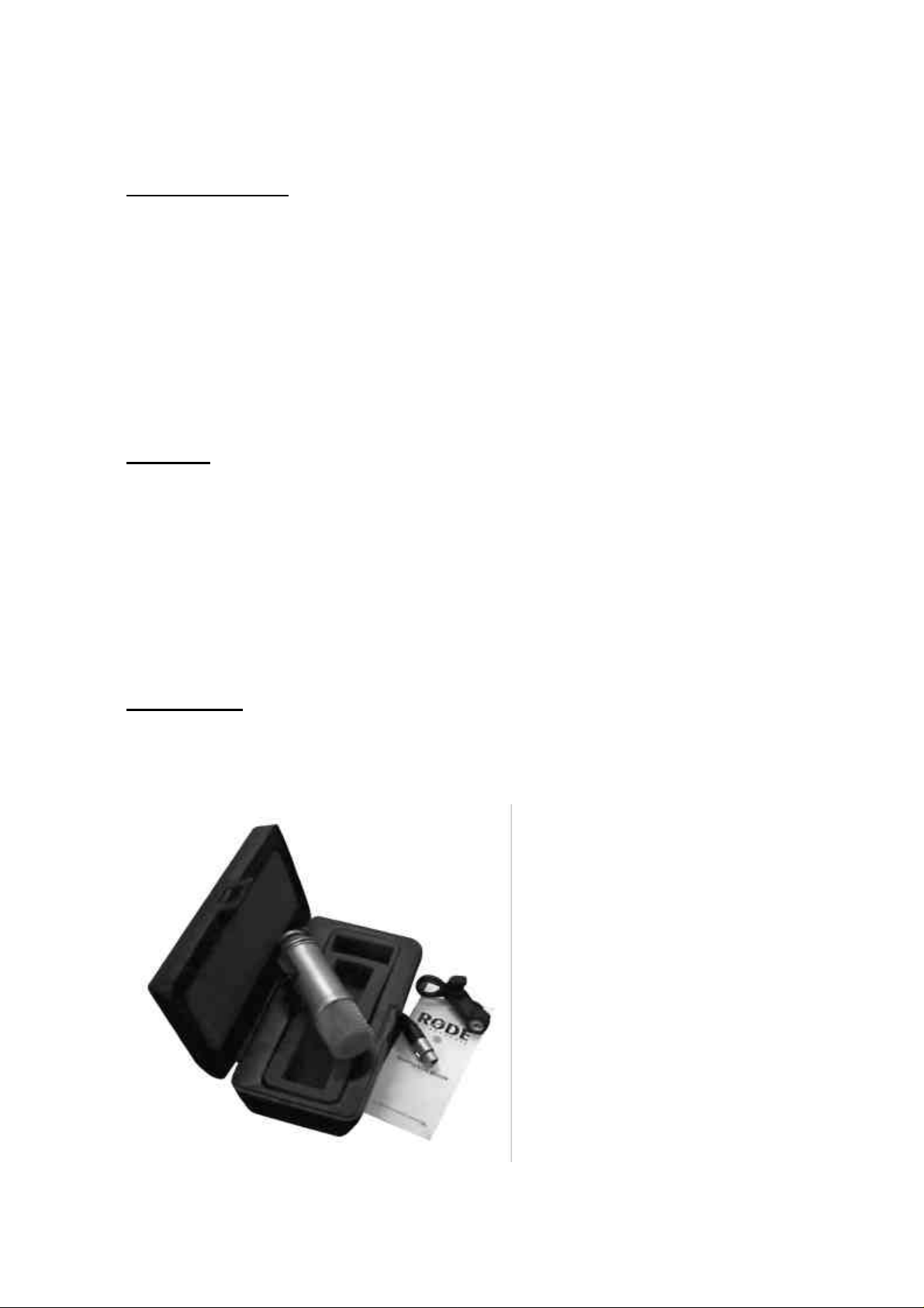
Accessories:
• BM1 Microphone Holder
• Custom High Impact Carry Case
• 5 Pin Plug

1. You will need a power supply to operate the
BROADCASTER. For optimum results, this
should be a 48V D.C. Phantom.
Most professional consoles have an internal
48V supply, or you can purchase one
separately. Make sure the power supply you
use is a professional unit that is operating
correctly. Damage caused by connecting the
BROADCASTER to a faulty power supply is
not covered by the guarantee.
2. The BROADCASTER comes complete with a
Micro-phone Mount (BM 1) and this must be
used to attach the BROADCASTER to a ‘stable’
microphone stand.
3. When first connecting the BROADCASTER
we suggest that you have the Gain control
adjusted to FULL attenuation (OFF).
4. Please make all cable connections before
applying power to the microphone. Never
remove the microphone cable while the power
is connected.
5. Check that you have the BROADCASTER
correctly connected. You can connect the
microphone directly to the mixer (without an
external supply) if 48V is available on the mixer.
Always use a balanced microphone cable and
be sure that the cable is a wired Pin 1 screen,
Pin 2+ Pin 3-, and 4 and 5 to switch the OnAir indicator if used (refer to Wiring Diagram).
We suggest you purchase a cable with goldplated plugs, as contact resistance due to
corrosion is a major cause of problems in all
sound systems.
6. Switch on the Power Supply/Mixer. The
Microphone will take a few seconds to
stabilize. Adjust the mixer gain so that the
Peak Programme light on the console
‘flashes’ on the ‘peaks’ of the sound source
(Voice). Be sure to do this at the same SPL
(volume) and distance you (or the announcer)
will work at. The BROADCASTER is now
ready for use.

7. Microphone technique, or how to get the
sound you want, requires experimentation.
Moving closer to the microphone increases the
perceived ‘warmth’ and ‘bass’ (Proximity
Effect). Try to get the sound you want by
placing either reflective or absorbent panels at
various angles adjacent to the source.
Changing the acoustic properties of the space
the microphone is in, is our recommended initial
approach for obtaining the best sound quality.
The BROADCASTER ‘ON-AIR’ INDICATOR:
While the BROADCASTERS’ output connection
and On-Air Indicator control is a very simple
operation to perform, we suggest that unless you
are familiar with cable connections and audio
installations in general, that you have an
Audio/Electronics Technician perform this task to
assure optimum performance.
The On-Air Indicator L.E.D. is switched either On
or Off by applying an open or closed circuit
across Pins 4 and 5 of the output connector.
When ‘open circuit’ (no connections across Pins 4
and 5), the L.E.D. is active. If you do not wish to
switch the L.E.D. via a console or separate mute
button, then the L.E.D. will be active continuously
whenever the microphone has P48V (Phantom
Power) applied.
Most professional consoles have switches that
provide both open circuit or short circuit outputs.
These are usually called ‘Channel On” or
‘Channel Mute’ controls and actually mute the
audio signal as well as providing external
contacts. These external contacts are usually
used to mute audio monitors and switch On-Air
lights at the same time as microphones become
active. These contacts can also be used to
activate the BROADCASTERS’ ‘On-Air’ indicator.
Remember, the L.E.D. does not interfere with the
audio circuit, and has no other function than that
of an indicator. The microphone does not mute
itself! The indicator is simply that; an indicator of
the status of what another device is doing.
(Console Muting).
A 5 Pin female connector is supplied, and you
can use a four-core screened (Quad) microphone
cable which is readily available from most
professional audio suppliers, or you can use any
cable which is a two-core screened plus 2 extra
control wires if the L.E.D is to be switched.

Some tips that may be helpful:
1. Condenser microphones do not like moisture!
The BROADCASTER, like all studio
microphones should be kept dry at all times.
The BROADCASTER is a precision
transducer and should be cared for as such.
Dropping or knocking the microphone can
damage it and so please ensure that the
microphone is securely fixed to a dedicated
microphone stand using the BM1 Mount
supplied.
*After every use, the BROADCASTER should be
removed from its stand, wiped down with a dry
soft cloth, and placed in its case. Be sure to place
the moisture-absorbent crystals (small pouch) at
the head of the microphone. The crystals will
absorb any moisture present. Eventually, this
pack needs to be dried. When the crystals have
turned pink, the pack should be placed in an oven
set to between 100-150oC. They will be activated
when they turn blue.
Note: There are no user serviceable parts inside
this microphone, and so there will never be a
reason for you to dismantle it. All service that
requires dismantling must be performed by a
qualified RØDE service agent to protect your
warranty.

Warranty Service:
All RØDE products are warrantied for one year
from date of purchase and the warranty card
should be used to register that purchase.
The warranty covers parts and labour that may be
required to repair the microphone during the
warranty period. The warranty excludes defects
caused by normal wear and tear, modification,
shipping damage, or failure to use the
microphone as per the instruction guide.
If you experience any problem, or have any
questions regarding your RØDE microphone,
first, contact the Dealer who sold it to you. If the
microphone requires Factory authorised service,
return will be organised by that Dealer. We have
an extensive Distributor/Dealer network, but if you
have difficulty getting the advice or assistance
you require, do not hesitate to contact us directly.
International: Tel: 61 -2 8765 9333
Fax: 61 -2 8765 9444
Australia: Tel: (02) 8765 9333
Fax: (02) 8765 9444
USA: Tel: 310-328-7456
Fax: 310-328-7180
e-mail information: info@rodemicrophones.com
www.rodemicrophones.com
or contact your local RØDE Distributor
 Loading...