


VIDEOMIC PRO
INSTRUCTION MANUAL
www.rodemic.com

INTRODUCTION |
CONTENTS |
Thank you for investing in the RØDE VideoMic Pro.
When RØDE released the original VideoMic in 2004 it was the only mic of its kind on the market. Just like many great innovations it was born from a personal need. At the time MiniDV cameras were the latest technology, offering consumers and independent filmmakers unprecedented freedom and creativity for their video, but neglecting audio quality. I went shopping for a solution but found that the only offerings were either cheap inferior quality or high cost shotgun microphones not designed to integrate easily with the cameras.
Thus the VideoMic was born. Almost a decade later its broadcast audio quality, integrated shock mounting and accessible price tag has made it the world’s largest selling microphone for consumer cameras.
However in this time there have been numerous innovations in video cameras, from hard drive, solid state and network cameras, through to high definition Digital SLR and onwards to large sensor video cameras. The technology has gotten larger but of course the form factor much smaller, thus the decision to create the high performance, yet conveniently compact VideoMic Pro.
Creating a high performance microphone as lightweight and manageable as the VideoMic Pro was quite a technical challenge. Other companies have attempted and failed, simply because a directional microphone depends on the length of the microphone barrel to reject the surrounding ambient noise that you don’t want to pick up.
Leveraging the technology developed alongside our award winning NTG1, NTG2 and NTG3 shotgun microphones we’ve finally realised a professional microphone with a much smaller form factor.
Please take the time to visit www.rodemic.com and register your mic for a full ten year warranty.
Peter Freedman
RØDE Microphones
Sydney, Australia
INTRODUCTION
SPECIFICATIONS
FEATURES
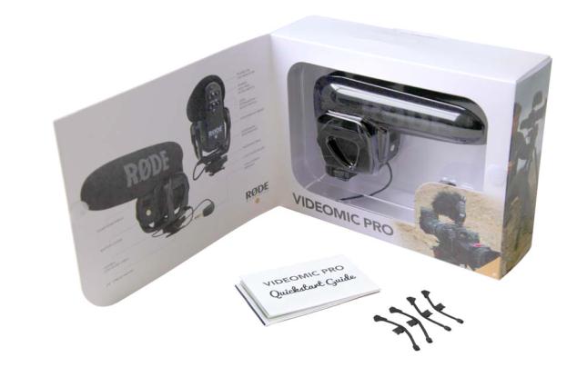
WHAT’S IN THE BOX
VIDEOMIC PRO STRUCTURE
SETUP AND USE
Installing the battery Mounting and connecting VideoMic Pro controls Replacing shock mount bands
Recording Tips
OPTIONAL ACCESSORIES
SAFETY / CARE INSTRUCTIONS
TROUBLESHOOTING / FAQ
PRODUCT WARRANTY
SUPPORT AND SERVICE
2.
3.
4.
4.
5.
6.
7.
8.
10.
12.
13.
15.
16.
18.
18.
2.

SPECIFICATIONS |
|
|
|
|
|
|
|
|
|
Acoustic Principle: |
Line gradient |
FREQUENCY RESPONSE |
|
|
|||||
|
|
|
|
|
|
|
|
||
Polar Pattern |
Super Cardioid |
|
|
|
|
|
|
|
|
Frequency Range: |
40 Hz ~ 20 000 Hz |
|
|
10 |
|
|
|
|
|
(High Pass Filter) |
@ 80 Hz / 12 dB /octave |
V./Pa |
|
0 |
|
|
|
|
|
-10 |
|
|
|
|
|
||||
Frequency Range: |
Selectable HPF |
|
|
|
|
|
|
|
|
|
3 position switch |
1 |
-20 |
|
|
|
|
|
|
Variable Level: |
re |
|
|
|
|
|
|||
(-10 dB, 0 dB, +20 dB) |
-30 |
|
|
|
|
|
|||
|
dB |
|
|
|
|
|
|||
|
|
|
|
|
|
|
|||
Output Impedence |
200 |
-40 |
|
|
|
|
|
||
|
|
|
|
|
|
||||
Signal to Noise Ratio: |
74 dB |
|
|
20 Hz |
100 |
1000 |
10 000 |
20 000 |
|
Equivalent Noise: |
20 dBA SPL |
|
|
|
|
|
|
|
|
(A-weighted as per IEC651) |
|
|
|
|
|
|
|
|
|
|
|
|
|
|
|
|
|
|
|
Maximum SPL: |
134 dB |
POLAR PATTERN |
|
|
|
||||
|
+6.9 dBu |
|
|
|
|||||
Maximum Output: |
|
|
|
|
|
|
|
|
|
(@ 1% THD into 1K load) |
|
|
|
|
|
|
|
|
|
|
|
|
|
|
|
0˚ |
|
|
|
|
|
+5.0 |
|
|
|
|
|
||
|
|
|
|
|
|
|
|
||
Sensitivity: |
-38 dB re 1V/Pa |
|
0.0 |
|
|
|
|
|
|
(12.6mV @ 94 dB SPL) |
|
|
|
|
-2.0 |
|
|
||
|
-2.0 |
|
|
|
|
|
|||
|
± 2 dB @ 1kHz |
|
-4.0 |
|
|
|
|
|
|
|
|
-6.0 |
|
|
|
|
|
|
|
|
|
|
-8.0 |
|
|
|
-10.0 |
|
|
Dynamic Range: |
114 dB SPL (as per IEC651) |
-10.0 |
|
|
|
|
|
||
-12.0 |
|
|
|
|
|
|
|||
|
|
-14.0 |
|
|
|
|
|
|
|
|
9V alkaline battery |
-16.0 |
|
|
|
|
|
|
|
Power requirements: |
-18.0 |
|
|
|
-20.0 |
|
|
||
-20.0 |
|
|
|
|
|
||||
(Current 7.8mA) |
-22.0 |
|
|
|
|
|
|||
|
|
|
|
|
|
|
|||
|
|
-24.0 |
-25.0 |
90˚ |
|
|
270˚ |
|
|
|
|
|
|
|
|
|
|||
|
3.5 Stereo mini jack plug |
dB rel. 1V/Pa |
|
|
|
|
|
||
|
|
|
|
|
|
|
|
|
|
Output Connection: |
(dual mono) |
|
|
|
|
|
|
|
|
Tip – left channel |
|
|
|
|
|
|
|
|
|
|
|
|
|
|
|
|
|
|
|
|
Ring – right channel |
Frequency: |
|
|
|
|
|
||
Battery Life: |
> 70 hours |
|
500 Hz: |
|
|
|
|
|
|
1000 Hz: |
|
|
|
|
|
||||
Weight (No Battery): |
86g (3oz) |
2000 Hz: |
|
|
|
|
|
||
8000 Hz: |
|
|
180˚ |
|
|
||||
|
43mm x 150mm x 95mm |
14000 Hz: |
|
|
|
|
|||
Dimension (W x L x H): |
|
|
|
|
|
|
|
|
|
(1.69” x 6” x 3.74”) |
|
|
|
|
|
|
|
|
|
|
|
|
|
|
|
|
|
|
|
3.
FEATURES |
WHAT’S IN THE BOX |
COMPACT SHOTGUN MICROPHONE
•Compact, lightweight body
•Broadcast recording quality
•Condenser microphone
•Integrated shock mount provides isolation from handling / mechanical noise
•Integrated foam windshield
•3.5mm stereo mini jack output (dual mono)
•Rugged construction
DETAILED CONTROL
•Two step high-pass filter (0, 80 Hz)
•Three position level control (-10dB, 0dB, +20dB)
•LED on / off power indicator
•Integrated billeted metal camera shoe mount with 3/8” thread for easy boompole mounting
HIGH QUALITY PERFORMANCE
•9V battery powered – over 70 hours use (alkaline)
•Low noise circuitry
•Flexible and lightweight cable to minimise handling noise and ensure isolation
•Australian designed and manufactured
•10 Year Warranty*
*Online product registration required.
•VideoMic Pro
•Spare shock mount bands (4 pieces)
•VideoMic Pro quick start guide
•Moisture absorbent crystals
4.
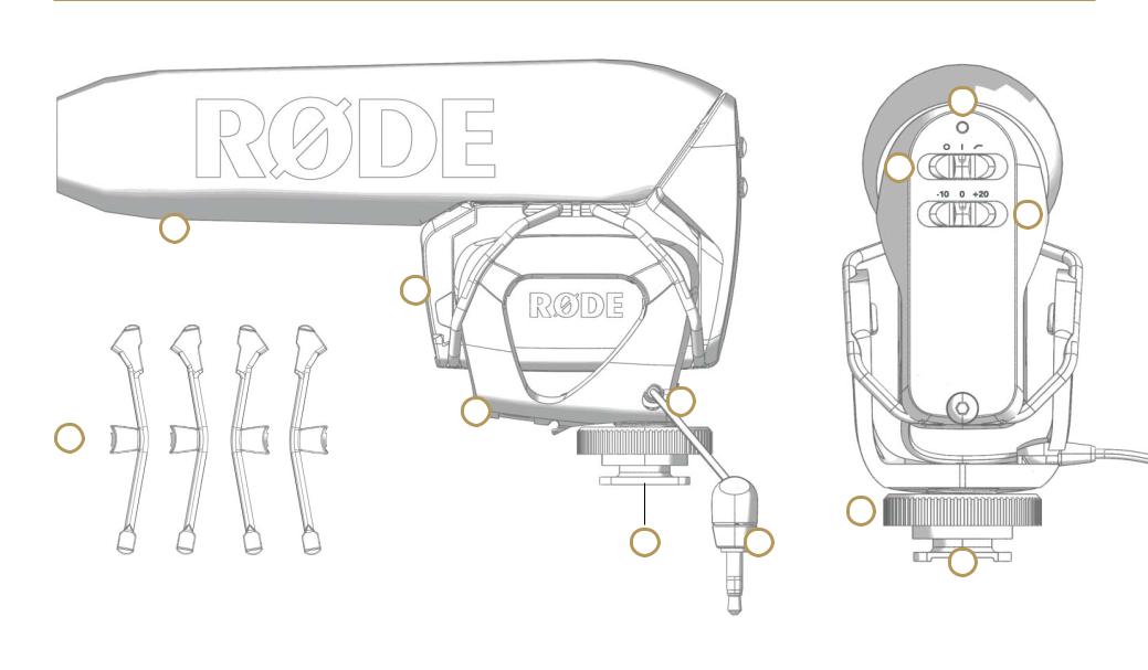
VIDEOMIC PRO STRUCTURE
6
4
5
1
7
2 |
11 |
|
3
9
10 12
8
1. |
Foam windshield |
8. |
Billeted metal |
2. |
Shock mount cradle |
|
camera shoe mount |
3. |
Shock mount band |
9. |
Fastening ring |
4. |
Power / High Pass Filter switch |
10. |
3/8” thread mount |
5. |
Level attenuation / boost switch |
11. |
Signal output cable |
6. |
Power on / off LED indicator |
12. |
3.5mm stereo mini jack |
7.Battery cover
5.

SETUP AND USE
INSTALLING THE BATTERY
Before you can record with your VideoMic Pro, you will need to install a standard 9V battery (ANS1:1604A or IEC:6LR61).
RØDE recommends using a high quality lithium or alkaline battery to achieve the best possible battery life.
To install the battery, open the battery cover that is located on the front of the VideoMic Pro, just under the windshield foam.
To remove the cover, hold the sides of the cover with your thumb and third finger, and push up on the indentation with your index finger, then pivot the bottom of the cover away.
Push up on the indentation with your index finger then pivot the bottom of the cover away
Insert the battery with the negative terminal (-) on top as shown in the next diagram. The correct battery orientation is also shown on the inside of the battery cover. If the battery orientation is incorrect the cover will not close fully.
Insert the battery with the negative terminal on top
Replace the cover by first hooking the top clips in, then press the bottom clips into place. The cover will push the battery against its spring terminal during installation.
6.
 Loading...