


 Loading...
Stratix 8000 Ethernet
Managed Switches
Hardware User Manual
Catalog Numbers 1783-MS06T, 1783-MS10T,
1783-MX08T, 1783-MX08F

Important User Information
Solid state equipment has operational characteristics differing from those of electromechanical equipment. Safety Guidelines for the Application, Installation and Maintenance of Solid State Controls (publication SGI-1.1 available from your local Rockwell Automation sales office or online at http://literature.rockwellautomation.com) describes some important differences between solid state equipment and hardwired electromechanical devices. Because of this difference, and also because of the wide variety of uses for solid state equipment, all persons responsible for applying this equipment must satisfy themselves that each intended application of this equipment is acceptable.
In no event will Rockwell Automation, Inc. be responsible or liable for indirect or consequential damages resulting from the use or application of this equipment.
The examples and diagrams in this manual are included solely for illustrative purposes. Because of the many variables and requirements associated with any particular installation, Rockwell Automation, Inc. cannot assume responsibility or liability for actual use based on the examples and diagrams.
No patent liability is assumed by Rockwell Automation, Inc. with respect to use of information, circuits, equipment, or software described in this manual.
Reproduction of the contents of this manual, in whole or in part, without written permission of Rockwell Automation, Inc., is prohibited.
Throughout this manual, when necessary, we use notes to make you aware of safety considerations.
WARNING
Identifies information about practices or circumstances that can cause an explosion in a hazardous environment, which may lead to personal injury or death, property damage, or economic loss.
|
IMPORTANT |
|
Identifies information that is critical for successful application and understanding of the product. |
|||||
|
|
|
||||||
|
|
|
|
|
|
|
|
|
|
|
|
|
|
|
|
|
|
|
|
|
|
|
|
|
|
Identifies information about practices or circumstances that can lead to personal injury or death, |
|
ATTENTION |
|||||||
|
property damage, or economic loss. Attentions help you identify a hazard, avoid a hazard, and |
|||||||
|
|
|
|
|
|
|
|
|
|
|
|
|
|
|
|
|
recognize the consequence |
|
|
|
|
|
|
|||
|
|
|
|
|
|
|
||
|
|
|
|
|
|
|||
|
|
|
|
|
|
|
|
Labels may be on or inside the equipment, for example, a drive or motor, to alert people that |
SHOCK HAZARD |
||||||||
|
|
|
|
|
|
|
|
dangerous voltage may be present. |
|
|
|
|
|
||||
|
|
|
|
|
|
|
||
|
|
|
||||||
|
|
|
|
|
|
|
|
Labels may be on or inside the equipment, for example, a drive or motor, to alert people that |
|
BURN HAZARD |
|||||||
|
|
|
|
|
|
|
|
surfaces may reach dangerous temperatures. |
|
|
|
|
|
|
|
|
|
|
|
|
|
|
|
|
|
|
Allen-Bradley, Rockwell Automation, RSLinx, RSLogix 5000, Stratix 8000, and TechConnect are trademarks of Rockwell Automation, Inc.
Trademarks not belonging to Rockwell Automation are property of their respective companies.

Preface
About This Publication
Who Should Use This
Publication
This publication describes the physical and performance characteristics of the Stratix 8000 Ethernet Managed Switches. In addition, this publication provides the following:
•Detailed installation information
•How to use the switch
•Troubleshooting information
This guide does not describe system messages that you might receive or how to configure your switch. For this information, see the Additional Resources section on page 6.
This guide is for the person installing Stratix 8000 Ethernet Managed Switches. We assume that you are familiar with the concepts and terminology of the Ethernet protocol and local area networking.
Publication 1783-UM002C-EN-P - April 2009 |
5 |

Preface
Additional Resources
These documents contain additional information concerning this Rockwell Automation product.
Resource |
Description |
|
|
Stratix 8000 Ethernet Managed Switches |
Describes how to get started installing and |
Installation Instructions, publication |
configuring the switch. |
1783-IN005 |
|
|
|
Stratix 8000 Ethernet Managed Switches |
Provides detailed information on configuring |
Software User Manual, publication |
and managing your switches. |
1783-UM003 |
|
|
|
Stratix 8000 Ethernet Managed Switches |
Lists enhancements and anomalies |
Release Notes, publication 1783-RN002 |
associated with the software release. |
|
|
Device Manager online help (provided with |
Provides context-sensitive information on |
the switch) |
configuring and using the switch, including |
|
system messages. |
|
|
Industrial Automation Wiring and |
Provides general guidelines for installing a |
Grounding Guidelines, publication |
Rockwell Automation industrial system. |
1770-4.1 |
|
|
|
Product Certifications website, |
Provides declarations of conformity, |
http://ab.com |
certificates, and other certification details. |
|
|
You can view or download publications at http://literature.rockwellautomation.com. To order paper copies of technical documentation, contact your local Rockwell Automation distributor or sales representative.
6 |
Publication 1783-UM002C-EN-P - April 2009 |

|
|
Table of Contents |
|
Preface |
|
|
About This Publication . . . . . . . . . . . . . . . . . . . . . |
. . . . . . . . . . . . . . . . . 5 |
|
Who Should Use This Publication . . . . . . . . . . . . |
. . . . . . . . . . . . . . . . . 5 |
|
Additional Resources . . . . . . . . . . . . . . . . . . . . . . . |
. . . . . . . . . . . . . . . . . 6 |
|
Chapter 1 |
|
Start |
About the Switches . . . . . . . . . . . . . . . . . . . . . . . . |
. . . . . . . . . . . . . . . . . 8 |
|
Power and Relay Connector . . . . . . . . . . . . . . . . . |
. . . . . . . . . . . . . . . . 11 |
|
Console Port. . . . . . . . . . . . . . . . . . . . . . . . . . . . . . |
. . . . . . . . . . . . . . . . 12 |
|
Dual-Purpose Uplink Ports . . . . . . . . . . . . . . . . . . |
. . . . . . . . . . . . . . . . 12 |
|
10/100 Ports. . . . . . . . . . . . . . . . . . . . . . . . . . . . . . |
. . . . . . . . . . . . . . . . 13 |
|
100BASE-FX Ports . . . . . . . . . . . . . . . . . . . . . . . . |
. . . . . . . . . . . . . . . . 13 |
|
Rear Panel. . . . . . . . . . . . . . . . . . . . . . . . . . . . . . . . |
. . . . . . . . . . . . . . . . 13 |
|
Cabling . . . . . . . . . . . . . . . . . . . . . . . . . . . . . . . . . . |
. . . . . . . . . . . . . . . . 14 |
|
Auto-MDIX Feature . . . . . . . . . . . . . . . . . . . . |
. . . . . . . . . . . . . . . . 14 |
|
Status Indicators . . . . . . . . . . . . . . . . . . . . . . . . . . . |
. . . . . . . . . . . . . . . . 15 |
|
Switch and Port Status Indicators . . . . . . . . . . |
. . . . . . . . . . . . . . . . 15 |
|
Dual-purpose Port Status Indicators . . . . . . . |
. . . . . . . . . . . . . . . . 17 |
|
Expansion Module Status Indicators . . . . . . . |
. . . . . . . . . . . . . . . . 18 |
|
CompactFlash Memory Card. . . . . . . . . . . . . . . . . |
. . . . . . . . . . . . . . . . 19 |
|
Chapter 2 |
|
Install the Switch |
Installation Guidelines . . . . . . . . . . . . . . . . . . . . . . |
. . . . . . . . . . . . . . . . 24 |
|
Environment and Enclosure Guidelines . . . . |
. . . . . . . . . . . . . . . . 24 |
|
Before You Begin. . . . . . . . . . . . . . . . . . . . . . . . . . |
. . . . . . . . . . . . . . . . 24 |
|
Place the Switch . . . . . . . . . . . . . . . . . . . . . . . . |
. . . . . . . . . . . . . . . . 25 |
|
Verify Package Contents . . . . . . . . . . . . . . . . . . . . |
. . . . . . . . . . . . . . . . 26 |
|
Add Modules to the Switch . . . . . . . . . . . . . . . . . . |
. . . . . . . . . . . . . . . . 26 |
|
Expansion Module Configurations . . . . . . . . . |
. . . . . . . . . . . . . . . . 26 |
|
Install the Switch . . . . . . . . . . . . . . . . . . . . . . . . . . |
. . . . . . . . . . . . . . . . 29 |
|
Attach Expansion Modules (optional) . . . . . . |
. . . . . . . . . . . . . . . . 29 |
|
Mount the Switch. . . . . . . . . . . . . . . . . . . . . . . |
. . . . . . . . . . . . . . . . 32 |
|
Install the SFP Module (optional). . . . . . . . . . |
. . . . . . . . . . . . . . . . 37 |
|
Ground the Switch. . . . . . . . . . . . . . . . . . . . . . |
. . . . . . . . . . . . . . . . 38 |
|
Wire the DC Power Source. . . . . . . . . . . . . . . |
. . . . . . . . . . . . . . . . 40 |
|
Attach the Power and Relay Connector . . . . . |
. . . . . . . . . . . . . . . . 42 |
|
Wire the External Alarms (Optional) . . . . . . . |
. . . . . . . . . . . . . . . . 44 |
|
Install or Remove the CompactFlash Card. . . . . . |
. . . . . . . . . . . . . . . . 47 |
|
Set Up the Switch Initially with Express Setup. . . |
. . . . . . . . . . . . . . . . 48 |
|
Configure and Manage the Switch. . . . . . . . . . . . . |
. . . . . . . . . . . . . . . . 53 |
|
Use the Device Manager Web Interface. . . . . |
. . . . . . . . . . . . . . . . 53 |
|
Use RSLogix 5000 Software . . . . . . . . . . . . . . |
. . . . . . . . . . . . . . . . 54 |
|
Download Cisco Network Assistant. . . . . . . . |
. . . . . . . . . . . . . . . . 56 |
|
Use the Command-Line Interface. . . . . . . . . . |
. . . . . . . . . . . . . . . . 57 |
|
Use SNMP Management Applications . . . . . . |
. . . . . . . . . . . . . . . . 57 |
Publication 1783-UM002C-EN-P - April 2009 |
3 |

|
Reset the Switch to Factory Defaults . . . . . . . . . . . . . . . . . . . . . . . . . . |
58 |
|
Connect to the Switch Ports . . . . . . . . . . . . . . . . . . . . . . . . . . . . . . . . . |
58 |
|
Connect to 10/100 Copper Ports . . . . . . . . . . . . . . . . . . . . . . . . . . |
59 |
|
Connect to Dual-purpose Uplink (10/100/1000 and SFP Fiber) |
|
|
Ports . . . . . . . . . . . . . . . . . . . . . . . . . . . . . . . . . . . . . . . . . . . . . . . . . |
59 |
|
Connect to 100BaseFX Ports . . . . . . . . . . . . . . . . . . . . . . . . . . . . . |
61 |
|
Verify Port Connectivity . . . . . . . . . . . . . . . . . . . . . . . . . . . . . . . . . . . . |
61 |
|
Verify Switch Operation . . . . . . . . . . . . . . . . . . . . . . . . . . . . . . . . . . . . |
62 |
|
Connect a Computer or a Terminal to the Console Port. . . . . . . . . . . |
62 |
|
Run a Power-on Self-test (POST) . . . . . . . . . . . . . . . . . . . . . . . . . . . . . |
63 |
|
Verify POST Results . . . . . . . . . . . . . . . . . . . . . . . . . . . . . . . . . . . . . . . |
63 |
|
Disconnect Power . . . . . . . . . . . . . . . . . . . . . . . . . . . . . . . . . . . . . . . . . |
64 |
|
Install and Remove SFP Modules . . . . . . . . . . . . . . . . . . . . . . . . . . . . . |
64 |
|
Install SFP Modules into SFP Module Slots . . . . . . . . . . . . . . . . . |
64 |
|
Remove SFP Modules from SFP Module Slots . . . . . . . . . . . . . . . |
65 |
|
Connect to SFP Modules. . . . . . . . . . . . . . . . . . . . . . . . . . . . . . . . . . . . |
67 |
|
Chapter 3 |
|
Troubleshoot the Switch |
Obtain Troubleshooting Information . . . . . . . . . . . . . . . . . . . . . . . . . . |
69 |
|
Verify Switch POST Results . . . . . . . . . . . . . . . . . . . . . . . . . . . . . . . . . |
69 |
|
View POST Results With a Terminal . . . . . . . . . . . . . . . . . . . . . . . |
70 |
|
Verify Switch Status Indicators . . . . . . . . . . . . . . . . . . . . . . . . . . . . . . . |
70 |
|
Verify Switch Connections . . . . . . . . . . . . . . . . . . . . . . . . . . . . . . . . . . |
70 |
|
Bad or Damaged Cable . . . . . . . . . . . . . . . . . . . . . . . . . . . . . . . . . . |
70 |
|
Ethernet and Fiber Cables. . . . . . . . . . . . . . . . . . . . . . . . . . . . . . . . |
71 |
|
Link Status . . . . . . . . . . . . . . . . . . . . . . . . . . . . . . . . . . . . . . . . . . . . |
72 |
|
Transceiver Issues . . . . . . . . . . . . . . . . . . . . . . . . . . . . . . . . . . . . . . |
72 |
|
Port and Interface Settings . . . . . . . . . . . . . . . . . . . . . . . . . . . . . . . |
73 |
|
Verify Switch Performance . . . . . . . . . . . . . . . . . . . . . . . . . . . . . . . . . . |
73 |
|
Speed, Duplex, and Autonegotiation . . . . . . . . . . . . . . . . . . . . . . . |
73 |
|
Autonegotiation and Network Interface Cards (NICs) . . . . . . . . . |
74 |
|
Cabling Distance . . . . . . . . . . . . . . . . . . . . . . . . . . . . . . . . . . . . . . . |
74 |
|
Obtain Configurtion Information . . . . . . . . . . . . . . . . . . . . . . . . . . . . . |
74 |
|
Chapter 4 |
|
Cable and Connectors |
10/100 and 10/100/1000 Ports . . . . . . . . . . . . . . . . . . . . . . . . . . . . . . |
75 |
|
Connect to 10BASE-T- and 100BASE-TX-Compatible Devices. 76 |
|
|
100BASE-FX Ports . . . . . . . . . . . . . . . . . . . . . . . . . . . . . . . . . . . . . . . . |
78 |
|
SFP Module Ports . . . . . . . . . . . . . . . . . . . . . . . . . . . . . . . . . . . . . . . . . |
78 |
|
Dual-purpose Ports . . . . . . . . . . . . . . . . . . . . . . . . . . . . . . . . . . . . . . . . |
79 |
|
Console Port. . . . . . . . . . . . . . . . . . . . . . . . . . . . . . . . . . . . . . . . . . . . . . |
79 |
|
Cable and Adapter Specifications . . . . . . . . . . . . . . . . . . . . . . . . . . . . . |
80 |
|
SFP Module Cable Specifications . . . . . . . . . . . . . . . . . . . . . . . . . . |
80 |
|
Adapter Pinouts . . . . . . . . . . . . . . . . . . . . . . . . . . . . . . . . . . . . . . . . . . . |
80 |
Index |
|
|
4 |
Publication 1783-UM002C-EN-P - April 2009 |

Chapter 1
Start
This chapter provides a functional overview of the switches and covers these topics.
Topic |
Page |
|
|
About the Switches |
8 |
|
|
Power and Relay Connector |
11 |
|
|
Console Port |
12 |
|
|
Dual-Purpose Uplink Ports |
12 |
|
|
10/100 Ports |
13 |
|
|
100BASE-FX Ports |
13 |
|
|
Rear Panel |
13 |
|
|
Cabling |
14 |
|
|
Status Indicators |
15 |
|
|
CompactFlash Memory Card |
19 |
|
|
Publication 1783-UM002C-EN-P - April 2009 |
7 |

Chapter 1
About the Switches
The Stratix 8000 Ethernet Managed Switches provide a rugged, easy-to-use, secure switching infrastructure for harsh environments. You can connect these switches to network devices such as servers, routers, and other switches. In industrial environments you can connect any Ethernet-enabled industrial communication devices including programmable logic controllers (PLCs), human-machine interfaces (HMIs), drives, sensors, and I/O.
You can mount the switches on a DIN rail in an industrial enclosure, on a wall, or panel.
Available Switches, Expansion Modules, and SFP Modules
Catalog Number |
|
Description |
|||
|
|
|
|
|
|
Switches |
|
|
|
|
|
|
|
|
|
|
|
1783-MS06T |
|
4 10/100BASE-T Ethernet ports and 2 dual-purpose ports, each with a 10/100/1000BASE-T copper port |
|||
|
|
and an SFP (small form-factor pluggable) module slot |
|||
|
|
|
|
|
|
1783-MS10T |
|
8 10/100BASE-T Ethernet ports and 2 dual-purpose ports, each with a 10/100/1000BASE-T copper port |
|||
|
|
and an SFP (small form-factor pluggable) module slot |
|||
|
|
|
|
|
|
Expansion Modules |
|
|
|
|
|
|
|
|
|
|
|
1783-MX08T |
|
Expansion module with 8 10/100BASE-T copper Ethernet ports |
|||
|
|
|
|
|
|
1783-MX08F |
|
Expansion module with 8 100BASE-FX fiber optic Ethernet ports |
|||
|
|
|
|
|
|
SFP Modules |
|
|
|
|
|
|
|
|
|
|
|
1783-SFP100FX |
|
100BASE-FX multi-mode fiber transceiver |
|||
|
|
|
|
|
|
1783-SFP1GSX |
|
1000BASE-SX multi-mode fiber transceiver |
|||
|
|
|
|
|
|
1783-SFP100LX |
|
100BASE-LX single-mode fiber transceiver |
|||
|
|
|
|
|
|
1783-SFP1GLX |
|
1000BASE-LX single-mode fiber transceiver |
|||
|
|
|
|
|
|
Required Components |
|
|
|
|
|
|
|
|
|
|
|
Catalog Number |
|
Description |
|||
|
|
|
|
|
|
1606-XL series (recommended) |
|
Class 2, 24V DC output power supplies |
|||
1606-XLP series (recommended) |
|
|
|
|
|
Or equivalent |
|
|
|
|
|
|
|
|
|
|
|
Spare Components |
|
|
|
|
|
|
|
|
|
|
|
Catalog Number |
|
|
Description |
||
|
|
|
|
|
|
1783-MCF |
|
|
CompactFlash card |
||
|
|
|
|
|
|
|
|
|
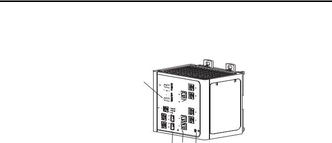
The switch front panel contains the ports, the status indicators, and the power |
||
|
|
|
and relay connectors. The following figures show the 1783-MS10T switch and |
||
|
|
|
expansion module front panels. |
||
8 |
Publication 1783-UM002C-EN-P - April 2009 |
Chapter 1
1783-MS10T Switch


|
. |
1Power and relay connectors
2Console port
3Dual-purpose ports
410/100 ports
5Protective ground connection
Publication 1783-UM002C-EN-P - April 2009 |
9 |
Chapter 1
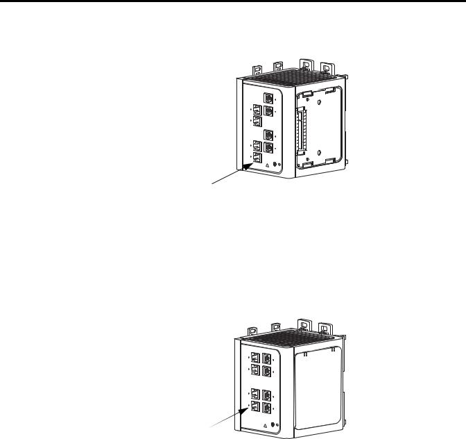
1783-MX08T Switch Copper Expansion Module (side cover removed)
1 |
|
31827-M |
|
||
|
|
1 10/100 ports
1783-MX08F Switch Fiber Expansion Module
1
31828-M
1 100BASE-FX ports
10 |
Publication 1783-UM002C-EN-P - April 2009 |
Chapter 1
Power and Relay Connector You connect the DC power and alarm signals to the switch through two front panel connectors. One connector provides primary DC power (supply A) and
the major alarm signal, and a second connector (supply B) provides secondary power and the minor alarm signal. The two connectors are physically identical and are in the upper left side of the front panel, as shown in the figure below.
The switch accessory pack includes the mating power and relay connectors. These connectors provide screw terminals for terminating the DC power and alarm wire and plug into the power and relay receptacles on the front panel. The positive DC power connection is labeled V, and the return is the adjacent connection labeled RT, as shown in the figure below.
V |
RT |
A |
A |
|
|||
|
|
||
|
|
|
|
|
|
|
31783-M |
The switch can operate with a single power source or with dual power sources. When both power sources are operational, the switch draws power from the DC source with the higher voltage. If one of the two power sources fail, the other continues to power the switch.
WARNING
When you connect or disconnect the power and relay connector with power applied, an electrical arc can occur. This could cause an explosion in hazardous area installations. Be sure that power is removed from the switch and alarm circuit. Be sure that power cannot be accidentally turned on or verify that the area is nonhazardous before proceeding.
Failure to securely tighten the power and relay connector captive screws can result in an electrical arc if the connector is accidentally removed.
The power and relay connectors also provide an interface for two independent alarm relays: the major alarm and the minor alarm. The relays can be activated for environmental, power supply, and port status alarm conditions and can be configured to indicate an alarm with either open or closed contacts. The relay itself is normally open, so under power failure conditions, the contacts are open. From the Command Line Interface (CLI), you can associate any alarm condition with one alarm relay or with both relays.
Alarm relays often control an external alarm device, such as a bell or a light. To connect an external alarm device to the relay, you must connect two relay contact wires to complete an electrical circuit. Both alarm terminals on the power and relay connector are labeled A. You can connect them without regard to polarity.
Publication 1783-UM002C-EN-P - April 2009 |
11 |

Chapter 1
Console Port
See the Stratix 8000 Ethernet Managed Switches Software User Manual, publication 1783-UM003A, for more information on alarm configuration..
For more information about the power and relay connector, see Chapter 4, Cable and Connectors.
For configuring, monitoring, and managing the switch, you can connect a switch to a computer through the console port and the supplied RJ45-to-DB-9 adapter cable. If you want to connect a switch to a terminal, you need to provide an RJ45-to-DB-25 female DTE adapter. For console-port and adapter-pinout information, see the Two Twisted-pair Straight-through Cable Schematic on page 76.
WARNING
If you connect or disconnect the console cable with power applied to the switch or any device on the network, an electrical arc can occur. This could cause an explosion in hazardous location installations. Be sure that power is removed or the area is nonhazardous before proceeding.
To verify switch operation, perform POST on the switch in a nonhazardous location before installation.
Dual-Purpose Uplink Ports The two dual-purpose uplink ports may each be configured for RJ45 (copper) or SFP (fiber) media types. Only one of these connections in each of the
dual-purpose ports can be active at a time. If both ports are connected, the SFP module port has priority.
You can set the copper RJ45 ports to operate at 10, 100, or 1000 Mb/s in full-duplex or half-duplex mode. You can configure them as fixed 10, 100, or 1000 Mb/s (Gigabit) Ethernet ports and can configure the duplex setting.
You can use approved Gigabit (or 100 Mbps) Ethernet SFP modules to establish fiber-optic connections to other switches. These transceiver modules are field-replaceable, providing the uplink interfaces when inserted in an SFP module slot. You use fiber-optic cables with LC connectors to connect to a fiber-optic SFP module. These ports operate in the full duplex mode only.
12 |
Publication 1783-UM002C-EN-P - April 2009 |
Chapter 1
10/100 Ports
100BASE-FX Ports
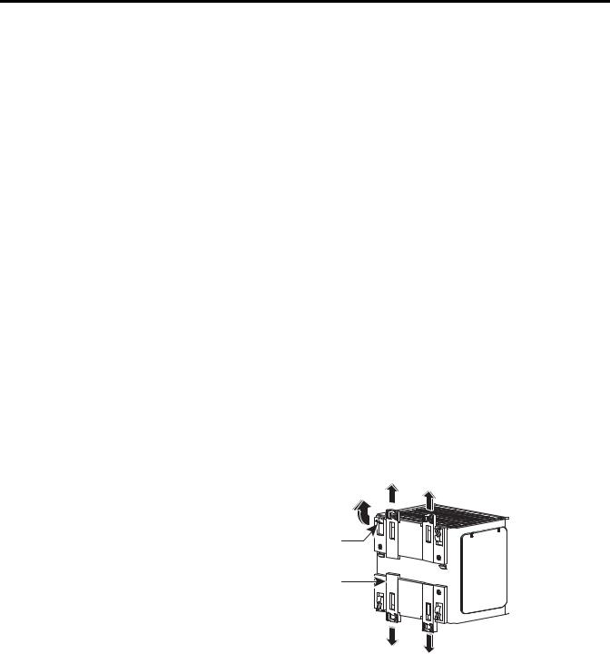
Rear Panel
You can set the 10/100 ports to operate at 10 or 100 Mb/s in full-duplex or half-duplex mode. You can also set these ports for speed and duplex autonegotiation in compliance with IEEE 802.3-2002. (The default setting is autonegotiate.)
When set for autonegotiation, the port senses the speed and duplex settings of the attached device. If the connected device also supports autonegotiation, the switch port negotiates the best connection (that is, the fastest line speed that both devices support and full-duplex transmission if the attached device supports it) and configures itself accordingly. In all cases, the attached device must be within 100 m (328 ft.) of the switch.
The IEEE 802.3-2002 100BASE-FX ports (on the 1783-MX08F expansion module) provide full-duplex 100 Mb/s connectivity over multimode fiber (MMF) cables. These ports use a built-in, small-form-factor fixed (SFF) fiber-optic transceiver module that accepts a dual LC connector. The cable can be up to 2 km (1.24 miles) in length.
The rear panel of the switches and expansion modules have latches for installation on either a DIN rail or a wall, as shown in the following figure. The latches slide outward to position the switch over the DIN rail and slide inward to secure the switch to a DIN rail. The feet must be extended when mounting the switch on heavy-duty (35 x 15mm) DIN rail or they may be extended for improved ventilation when wall mounting.
Foot
Latch
31777-M
Publication 1783-UM002C-EN-P - April 2009 |
13 |

Chapter 1
Cabling
100BASE-TX traffic requires Category 5 cable. 10BASE-T traffic can use Category 3 or Category 4 cables.
When connecting the switch to workstations, servers, and routers, straight-through cables are normally used. However, the automatic medium-dependent interface crossover (auto-MDIX) feature of the switch is enabled by default and will automatically re-configure the ports to use either straight-through or crossover cable type.
Auto-MDIX Feature
The Auto-MDIX feature is enabled by default. When the auto-MDIX feature is enabled, the switch detects the required cable type (straight-through or crossover) for copper Ethernet connections and configures the interfaces accordingly.
You can use the command-line interface (CLI) to disable the auto-MDIX feature. See the online help for more information.
14 |
Publication 1783-UM002C-EN-P - April 2009 |

Chapter 1
Status Indicators
The switches and expansion modules have these status indicators.
Switch and Port Status Indicators
V |
 RT
RT
A |
A |
EIP Mod Status Indicator 


EIP Net Status Indicator
Setup Status Indicator
|
|
PWR B Status Indicator |
PWR A Status |
Port Status Indicator |
|
|
|
Indicator |
|||
|
|
|
|
||
|
|
|
|
Dual-purpose Port |
|
|
|
|
|
Status Indicator |
31793-M |
|
|
|
|
|
|
Indicator |
State |
|
Description |
|
|
|
|
|
|
||
EIP Mod |
Off |
|
No power. Check the power supply and cabling. |
||
(EtherNet/IP module status) |
|
|
|
|
|
Solid green |
|
The switch is operating properly. |
|
||
|
|
|
|
||
|
Flashing green |
|
The switch has not been configured as a managed switch (for example, |
||
|
|
|
Express Setup was not performed, no IP address, no password). The |
||
|
|
|
switch is operating as an unmanaged switch. |
||
|
|
|
|
||
|
Flashing red |
|
A recoverable minor fault, such as an incorrect configuration, has |
||
|
|
|
occurred. |
|
|
|
|
|
|
||
|
Solid red |
|
A non-recoverable major fault has occurred. Cycle power. If the |
||
|
|
|
problem persists, contact Rockwell Automation Technical Support. |
||
|
|
|
|
||
|
Flashing green/red |
|
The switch is performing a power-on self-test (POST). |
||
|
|
|
|
|
|
EIP Net |
Off |
|
No power or no IP address. |
|
|
(EtherNet/IP network |
|
|
• Check the power supply and cabling. |
|
|
status) |
|
|
|
||
|
|
|
• Make sure switch is properly configured. |
||
|
|
|
|
||
|
Solid green |
|
The device has at least one established EtherNet/IP connection. |
||
|
|
|
|
||
|
Flashing green |
|
No EtherNet/IP connection yet, but the switch has obtained an IP |
||
|
|
|
address. |
|
|
|
|
|
|
|
|
|
Flashing red |
|
EtherNet/IP connection has timed out. |
|
|
|
|
|
|
||
|
Solid red |
|
Duplicate IP address. The switch has detected that its IP address is |
||
|
|
|
already in use. |
|
|
|
|
|
|
||
|
Flashing green/red |
|
The switch is performing a power-on self-test (POST). |
||
|
|
|
|
|
|
Publication 1783-UM002C-EN-P - April 2009 |
15 |

Chapter 1
Indicator |
State |
Description |
|
|
|
|
|
Setup |
Off |
Switch is configured as a managed switch. |
|
|
|
|
|
|
Solid green |
Switch is in initial setup. |
|
|
|
|
|
|
Flashing green |
Switch is in one of the following states; |
|
|
|
• initial setup |
|
|
|
• recovery |
|
|
|
• initial setup incomplete |
|
|
|
|
|
|
Solid red |
Switch failed to start initial setup or recovery because there is no |
|
|
|
available switch port to which to connect the management station. |
|
|
|
Disconnect a device from a switch port, and press the Express Setup |
|
|
|
button. |
|
|
|
|
|
PWR A and PWR B |
Off |
Power is not present on the circuit, or power is not applied to the |
|
(see PWR A and PWR B |
|
system. |
|
Status Indicators, below) |
|
|
|
Solid green |
Power is present on the associated circuit. |
||
|
|||
|
|
|
|
Port |
Off |
No link. |
|
|
|
|
|
|
Solid green |
Link present. |
|
|
|
|
|
|
Flashing green |
Activity. Port is sending or receiving data. |
|
|
|
|
|
|
Flashing amber |
A link blocked by spanning tree violation is sending or receiving data. |
|
|
|
|
|
|
Alternating green/amber |
Link fault. Error frames can affect connectivity, and errors such as |
|
|
|
excessive collisions, CRC errors, and alignment and jabber errors are |
|
|
|
monitored for a link-fault indication (RJ45 connection only). |
|
|
|
|
|
|
Solid amber |
Port is not forwarding. Port was disabled by management, an address |
|
|
|
violation, or spanning tree violation. |
|
|
|
After a port is reconfigured, the port status indicator can remain amber |
|
|
|
for up to 30 seconds while spanning tree checks the network for |
|
|
|
possible loops. |
|
|
|
|
PWR A and PWR B Status Indicators
If the switch has dual power sources (for redundancy), the switch draws power from the power source with the higher voltage. If one of the DC power sources fails, the alternate DC power source powers the switch.
If |
The Status Indicator Color Is |
Power is present on the PWR A or PWR B |
Green |
input |
|
Power is not present on the PWR or PWR B input
Red when power is not present, if switch is configured for dual input power.
Off if the switch is not configured for dual-input power.
16 |
Publication 1783-UM002C-EN-P - April 2009 |

Chapter 1
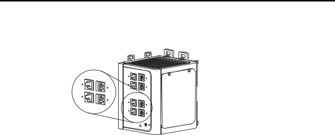
Dual-purpose Port Status Indicators
The status indicators on a dual-purpose port, as shown in the following figure, show whether the RJ45 connector or an SFP module is active. The port can be configured as either a 10/100/1000 port through the RJ45 connector or as an SFP module, but not both. The status indicators show which port is being used, and current port activity.
|
|
RJ45 Port In-use and Activity |
|
|
Status Indicator |
|
RJ45 Port |
SFP Module Port |
|
|
SFP Module Port In-use and Activity Status Indicator |
|
|
|
State |
Description |
|
|
|
|
Off |
No link. |
|
|
|
|
Solid green |
Link present. |
|
|
|
|
Flashing green |
Activity. Port is sending or receiving data. |
|
|
|
|
Flashing amber |
A link blocked by spanning tree is sending or receiving data. |
|
|
|
|
Alternating |
Link fault. Error frames can affect connectivity, and errors such as excessive collisions, CRC errors, and alignment and |
|
green/amber |
jabber errors are monitored for a link-fault indication (RJ45 connection only). |
|
|
|
|
Solid amber |
Port is not forwarding. Port was disabled by management, an address violation, or spanning tree violation. |
|
|
After a port is reconfigured, the port status indicator can remain amber for up to 30 seconds while spanning tree |
|
|
checks the network for possible loops. |
|
|
|
|
Publication 1783-UM002C-EN-P - April 2009 |
17 |
Chapter 1
Expansion Module Status Indicators
|
|
|
|
|
|
|
|
|
|
|
|
|
|
|
|
|
|
|
|
|
|
|
|
State |
Description |
||||
|
|
|
|
|
|
Off |
No link. |
||||
|
|
|
|
|
|
Solid green |
Link present. |
||||
|
|
|
|
|
|
Flashing green |
Activity. Port is sending or receiving data. |
||||
|
|
|
|
|
|
Flashing amber |
A link blocked by spanning tree is sending or receiving data. |
||||
|
|
|
|
|
|
Alternating |
Link fault. Error frames can affect connectivity, and errors such as excessive collisions, CRC errors, and alignment and |
||||
green/amber |
jabber errors are monitored for a link-fault indication (RJ45 connection only). |
||||
|
|
|
|
|
|
Solid amber |
Port is not forwarding. Port was disabled by management, an address violation, or spanning tree violation. |
||||
|
After a port is reconfigured, the port status indicator can remain amber for up to 30 seconds while spanning tree checks |
||||
|
the network for possible loops. |
||||
|
|
|
|
|
|
18 |
Publication 1783-UM002C-EN-P - April 2009 |

Chapter 1
CompactFlash Memory
Card
The switch supports a CompactFlash memory card that makes it possible to replace the switch without reconfiguring the switch. The slot for the CompactFlash memory card is on the bottom of the switch as shown in the following figure.
V |
 A RT
A RT

A |
31792-M
Although the switch is shipped with the CompactFlash memory card installed, you can insert or remove the CompactFlash memory card by grasping the tab on the card and either inserting it or removing it from the slot at the bottom of the switch.
TIP |
Refer to Install or Remove the CompactFlash Card on page 47. |
|
for more information on inserting and removing the |
||
|
||
|
||
|
CompactFlash memory card. |
Publication 1783-UM002C-EN-P - April 2009 |
19 |

Chapter 1
Notes:
20 |
Publication 1783-UM002C-EN-P - April 2009 |
Chapter 2
Install the Switch
This chapter describes how to install your switch, interpret the power-on self-test (POST), and connect the switch to other devices.
Read these topics, and perform the procedures in this order.
Topic |
Page |
|
|
Installation Guidelines |
24 |
|
|
Before You Begin |
24 |
|
|
Verify Package Contents |
26 |
|
|
Add Modules to the Switch |
26 |
|
|
Install the Switch |
29 |
|
|
Install or Remove the CompactFlash Card |
47 |
|
|
Set Up the Switch Initially with Express Setup |
48 |
|
|
Configure and Manage the Switch |
53 |
|
|
Reset the Switch to Factory Defaults |
58 |
|
|
Connect to the Switch Ports |
58 |
|
|
Verify Port Connectivity |
61 |
|
|
Verify Switch Operation |
62 |
|
|
Connect a Computer or a Terminal to the Console Port |
62 |
|
|
Run a Power-on Self-test (POST) |
63 |
|
|
Verify POST Results |
63 |
|
|
Verify POST Results |
63 |
|
|
Disconnect Power |
64 |
|
|
Install and Remove SFP Modules |
64 |
|
|
Connect to SFP Modules |
67 |
|
|
Publication 1783-UM002C-EN-P - April 2009 |
21 |

Chapter 2
WARNING
This equipment is intended to be grounded. Ensure that the host is connected to earth ground during normal use.
Before working on equipment that is connected to power lines, remove jewelry (including rings, necklaces, and watches). Metal objects will heat up when connected to power and ground and can cause serious burns or weld the metal object to the terminals.
Do not stack the chassis on any other equipment. If the chassis falls, it can cause severe bodily injury and equipment damage.
An exposed wire lead from a DC-input power source can conduct harmful levels of electricity. Be sure that no exposed portion of the DC-input power source wire extends from the power and relay connector.
Ultimate disposal of this product should be handled according to all national laws and regulations.
Do not work on the system or connect or disconnect cables during periods of lightning activity.
Before performing any of the following procedures, ensure that power is removed from the DC circuit.
Read the installation instructions before you connect the system to its power source.
This product relies on the building’s installation for short-circuit (overcurrent) protection. Ensure that the protective device is rated not greater than 5A.
This unit is intended for installation in restricted access areas. A restricted access area can be accessed only through the use of a special tool, lock and key, or other means of security.
A readily accessible two-poled disconnect device must be incorporated in the fixed wiring.
This equipment must be grounded. Never defeat the ground conductor or operate the equipment in the absence of a suitably installed ground conductor. Contact the appropriate electrical inspection authority or an electrician if you are uncertain that suitable grounding is available.
This unit might have more than one power supply connection. All connections must be removed to de-energize the unit.
Only trained and qualified personnel should be allowed to install, replace, or service this equipment. Ultimate disposal of this product should be handled according to all national laws and regulations.
For connections outside the building where the equipment is installed, the following ports must be connected through an approved network termination unit with integral circuit protection: 10/100/1000 Ethernet
When installing or replacing the unit, the ground connection must always be made first and disconnected last.
To prevent the system from overheating, do not operate it in an area that exceeds the maximum recommended ambient temperature of 167 °F (75 °C).
This equipment is supplied as “open type” equipment. It must be mounted within an enclosure that is suitably designed for those specific environmental conditions that will be present and appropriately designed to prevent personal injury resulting from accessibility to live parts. The interior of the enclosure must be accessible only by the use of a tool.
The enclosure must meet IP 54 or NEMA type 4 minimum enclosure rating standards.
22 |
Publication 1783-UM002C-EN-P - April 2009 |

Chapter 2
WARNING
This equipment is intended to be grounded to comply with emission and immunity requirements. Ensure that the switch functional ground lug is connected to earth ground during normal use.
When used in a Class I, Division 2, hazardous location, this equipment must be mounted in a suitable enclosure with proper wiring method, for all power, input and output wiring, that complies with the governing electrical codes and in accordance with the authority having jurisdiction over Class I, Division 2 installations.
Use twisted-pair supply wires suitable for 30 °C (86 °F) above surrounding ambient temperature outside the enclosure.
This equipment is intended for use in a Pollution Degree 2 industrial environment, in overvoltage Category II applications (as defined in IEC publication 60664-1), and at altitudes up to 2000 m (6,561.68 ft) without derating.
Installation of the equipment must comply with local and national electrical codes.
To prevent airflow restriction, allow clearance around the ventilation openings to be at least 105 mm (4.13 in.).
ATTENTION |
This equipment is only suitable for use in Class I, Division 2, |
|||
Groups A, B, C, D, or non hazardous locations. |
||||
|
|
|
||
|
|
|
||
|
|
|
Connect the unit only to a Class 2 DC power source. |
|
|
|
|
|
|
|
|
|
|
|
|
|
|
|
|
Publication 1783-UM002C-EN-P - April 2009 |
23 |

Chapter 2
Installation Guidelines
Before You Begin
When determining where to place the switch, observe these guidelines.
Environment and Enclosure Guidelines
Review these environmental guidelines before installation.
•This equipment is intended for use in a Pollution Degree 2 industrial environment, in overvoltage Category II applications (as defined in IEC publication 60664-1), at altitudes up to 3 km (9842 ft) without derating.
•This equipment is considered Group 1, Class A industrial equipment, according to IEC/CISPR Publication 11. Without appropriate precautions, there may be potential difficulties ensuring electromagnetic compatibility in other environments due to conducted as well as radiated disturbance.
•This equipment is supplied as open-type equipment. It must be mounted within an enclosure that is suitably designed for those specific environmental conditions that will be present and appropriately designed to prevent personal injury resulting from accessibility to live parts. The enclosure must have suitable flame-retardant properties to prevent or minimize the spread of flame, complying with a flame-spread rating of 5VA, V2, V1, V0 (or equivalent) if nonmetallic. The interior of the enclosure must be accessible only by the use of a tool.
Keep these points in mind when installing the switch.
•Proper ESD protection is required whenever you handle this equipment. Installation and maintenance personnel should be properly grounded by using ground straps to eliminate the risk of ESD damage to the switch.
•Do not touch connectors or pins on component boards. Do not touch circuit components inside the switch. When not in use, store the equipment in appropriate static-safe packaging.
•Personnel responsible for the application of safety-related Programmable Electronic Systems (PES) shall be aware of the safety requirements in the application of the system and shall be trained in using the system.
•Unless panel-mounted, this product is grounded through the DIN rail to chassis ground. Use zinc-plated yellow-chromate steel DIN rail to assure proper grounding. The use of other DIN rail materials (such as aluminum, plastic, and so on.) that can corrode, oxidize, or are poor conductors, can result in improper or intermittent grounding. Secure the DIN rail to the mounting surface approximately every 200 mm (7.8 in.), and use end-anchors appropriately.
24 |
Publication 1783-UM002C-EN-P - April 2009 |

Chapter 2
Place the Switch
When determining where to place the switch, observe these guidelines
•Before attaching the switch to the network, first verify that the switch is operational by powering it on and running POST. Follow the procedures in the Verify Switch Operation section on page 62.
•For 10/100 ports and 10/100/1000 ports, the cable length from a switch to an attached device cannot exceed 100 m (328 ft).
•For 100BASE-FX fiber-optic ports, the cable length from a switch to an attached device cannot exceed 2 km (6562 ft).
•Operating environment is within the ranges listed in the Stratix 8000 Ethernet Managed Switch Installation Instructions, publication 1783-IN005.
•Clearance to front and rear panels meet these conditions:
–Front-panel status indicators can be easily read.
–Access to ports is sufficient for unrestricted cabling.
–Front-panel direct current (DC) power and relay connector is within reach of the connection to the DC power source.
•Airflow around the switch and through the vents is unrestricted. To prevent the switch from overheating, provide the following minimum clearances:
–Top and bottom: 105 mm (4.13 in.)
–Exposed side (not connected to the module): 90 mm (3.54 in.)
–Front: 65 mm (2.56 in.)
•Temperature surrounding the unit does not exceed 75 °C (167 °F)
ATTENTION |
When the switch is installed in an industrial enclosure, the |
|||
temperature within the enclosure is greater than normal room |
||||
|
|
|
||
|
|
|
||
|
|
|
temperature outside the enclosure. |
|
|
|
|
The temperature inside the enclosure cannot exceed 75 oC |
|
|
|
|
||
|
|
|
||
(167 oF), the maximum ambient enclosure temperature of the switch.
•Cabling is away from sources of electrical noise, such as radios, power lines, and fluorescent lighting fixtures.
Publication 1783-UM002C-EN-P - April 2009 |
25 |

Chapter 2
Verify Package Contents |
Carefully remove the contents from the shipping container, and check each |
|
|
item for damage. If any item is missing or damaged, contact your Rockwell |
|
|
Automation representative for assistance. |
|
|
The switch is shipped with these items. |
|
|
• Stratix 8000 Ethernet Managed Switches Installation Instructions, |
|
|
publication 1783-IN005. |
|
|
• Two power and relay connectors |
|
|
• RJ45 to DB-9 console port adapter cable |
|
|
• CompactFlash card |
|
|
|
|
|
|
To connect the switch functional ground, you need a ring terminal lug |
|
IMPORTANT |
|
|
|
(such as Thomas & Bett part number 10RCR or equivalent). |
|
|
|
|
If you want to connect a terminal to the switch console port, you need to |
|
|
provide an RJ45-to-DB-25 female DTE adapter. For multimode (MM) |
|
|
connections, you can connect a 100BASE-FX port to a port on a target device |
|
|
by using dual-LC connector. |
|
|
The switch expansion modules are optional, and do not ship with the switch. |
|
|
You need to order these separately. |
|
Add Modules to the Switch |
The switches can operate as standalone devices with four or eight Fast |
|
|
Ethernet ports, respectively. To increase the number of Fast Ethernet ports by |
|
8 or 16, you can connect the optional expansion modules. Depending on the mix of switches and expansion modules, you can have up to 24 Fast Ethernet ports. The expansion modules cannot operate as standalone devices.
Expansion Module Configurations
To increase the number of ports, add one or two expansion modules to the switch. If you are installing only one module, it can be either an 1783-MX08T copper expansion module, or a 1783-MX08F fiber expansion module. If you are installing two modules, the first must be an 1783-MX08T copper expansion module, and the second can be either an 1783-MX08T copper expansion module, or a 1783-MX08F fiber expansion module. You cannot add two 1783-MX08F fiber expansion modules.
26 |
Publication 1783-UM002C-EN-P - April 2009 |

Chapter 2
|
|
|
|
The following table lists some port combinations using switch and expansion |
|
|
|
|
|
modules. |
|
Switch and Expansion Module Port Combinations |
|||||
|
|
|
|
|
|
|
|
Port Type |
|
Switch and Expansion Modules Combination |
|
|
100FE |
|
100FX |
|
|
|
|
|
|
||
|
(copper) |
|
(fiber optic) |
|
|
|
|
|
|
|
|
4 |
|
|
|
one 1783-MS06T switch |
|
|
|
|
|
|
|
8 |
|
|
|
one 1783-MS10T switch |
|
|
|
|
|
|
|
4 |
|
8 |
|
one 1783-MS06T switch |
|
|
|
|
|
|
one 1783-MX08F expansion module |
|
|
|
|
|
|
12 |
|
|
|
one 1783-MS06T switch |
|
|
|
|
|
|
one 1783-MX08T expansion module |
|
|
|
|
|
|
8 |
|
8 |
|
one 1783-MS10T switch |
|
|
|
|
|
|
one 1783-MX08F expansion module |
|
|
|
|
|
|
16 |
|
|
|
one 1783-MS10T switch |
|
|
|
|
|
|
one 1783-MX08T expansion module |
|
|
|
|
|
|
12 |
|
8 |
|
one 1783-MS06T switch |
|
|
|
|
|
|
one 1783-MX08T expansion module |
|
|
|
|
|
one 1783-MX08F expansion module |
|
|
|
|
|
|
20 |
|
|
|
one 1783-MS06T switch |
|
|
|
|
|
|
two 1783-MX08T expansion modules |
|
|
|
|
|
|
16 |
|
8 |
|
one 1783-MS10T switch |
|
|
|
|
|
|
one 1783-MX08T expansion module |
|
|
|
|
|
one 1783-MX08F expansion module |
|
|
|
|
|
|
24 |
|
|
|
one 1783-MS10T switch |
|
|
|
|
|
|
two 1783-MX08T expansion modules |
|
|
|
|
|
|
|
|
|
|
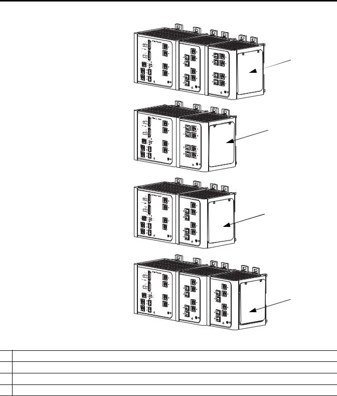
The following figure displays example combinations of the 1783-MS06T |
|
|
|
|
|
switch and expansion modules. The same combinations of expansion modules |
|
|
|
|
|
can be used with a 1783-MS10T switch. |
|
Publication 1783-UM002C-EN-P - April 2009 |
27 |
Chapter 2
1
2
3
1 

4
11783-MS06T switch with 1783-MX08T and 1783-MX08F expansion modules (12 copper and 8 fiber optic ports)
21783-MS06T switch with one 1783-MX08F expansion module (4 copper and 8 fiber optic ports)
31783-MS06T switch with one 1783-MX08T expansion modules (12 copper ports)
41783-MS06T switch with two 1783-MX08T expansion modules (20 copper ports)
28 |
Publication 1783-UM002C-EN-P - April 2009 |
Loading...