

Page 1

ICS Regent
®
PD-6019
DC Guarded Digital Output Modules
24 VDC, 48 VDC and 120 VDC
(T3461A, T3462A and T3468A)
Issue 1,
DC Guarded output modules provide Guarded switching of
user-supplied DC voltages to a maximum of eight field loads.
These
dual-redundant design ensures that no single fault within the
module will inadvertently apply power to an output.
Extensive fault detection and redundant critical circuits
ensure that each module operates in a fail-safe manner.
modules are called Guarded because each module's
March, 06
Features
·
Eight Guarded output circuits configured as two sepa
powered groups of four circuits each.
·
Fault tolerant operation when connected in parallel with
an
·
Hot-replaceable.
·
100% self-testing of all critical circuits.
·
Individual front panel indicators on each module show active
and fault, shutdown state, blown fuse, and output on/off status
(logic side).
·
2500 volt minimum electrical isolation between field and logic
circuits.
·
TÜV certified, Risk Class 5.
Two Guard
obtain fault tolerant control of power to loads. In this parallel
module configuration, either module can be removed and
replaced while the other Guarded module continues to control
the loads without interruption.
other module of the same type.
ed output modules can be connected in parallel to
rately
Industrial Control Services
1
Page 2
DC Guarded Digital Output Modules (T3461A, 62A, 68A)
Module Operation
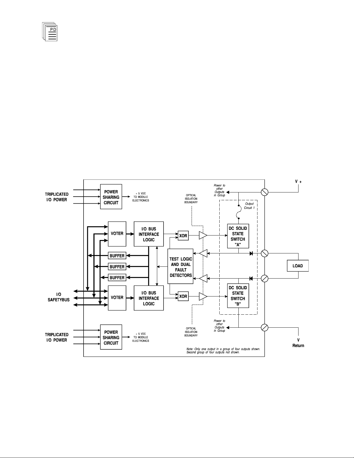
A block diagram of a typical monitored Guarded output
module is shown in Figure 1.
The processor modules send triplicated write data commands
over the I/O Safetybus to the Guarded output module.
Onboard the Guarded output modules the triplicated data are
routed to two independent voter and I/O Safetybus logic
sections. Each section independently votes the triplicated
data and operates one of the two field effect transistor (FET)
output control switches. The two FETs are connected in series
with the load.
2
Figure 1. Block Diagram of a DC Guarded Output Module.
When both circuits are on, current will flow through the
output and energize a field load. If e
will not flow through the output and the load will be de
Industrial Control Services
ither switch is off, current
-
Page 3

(T3461A, 62A, 68A) DC Guarded Digital Output Modules
Case
Commanded
Output St
ate
Switch
Failed
State
Actual
Output
to Load
Remarks
1 On
On On
Continued correct control.
Automatic testing detects
stuck-on switch. If output is
subsequently commanded
off, output will turn off.
2 On
Off Off
Fail-safe output. Automatic
testing detects stuck-off
switch.
3 Off
On
Off
Continued correct control.
Automatic testing detects
stuck-off switch. If output is
subsequently commanded
on, output will turn on.
4 Off
Off Off
Fail-safe output. Automatic
testing detects stuck-off
switch. If ou
tput is subse
quently commanded on,
output will remain off.
energized. This combination of series output switches and
independent drive signals produces fail-safe activation of the
load. Single failures can only affect one of the output drive
signals or switches. A single failure will result in either
continued correct control or a fail-safe output as shown in
Table 1.
Table 1. Output States After Switch Failure.
PD-6019
Mar-06
To achieve fault tolerance, two Guarded output modules are
used with their outputs connected in parallel. This
configuration provides for continued correct control even
when one output switch fails off (cases two and four in Table
1
). The module failure is automatically detected and the
module can be removed and replaced without interrupting
output control.
Testing and Diagnostics
The voter and I/O bus interface logic o
f the Guarded output
modules is automatically tested by the processor modules.
Discrepant data are sent through one of three legs of the I/O
Safetybus to determine whether the module’s voters are able
to outvote the incorrect data. A failure to return the correct
3
Page 4

DC Guarded Digital Output Modules (T3461A, 62A, 68A)
majority-voted result to the processors produces an I/O
module error indication at the processor modules and a
module fault indication at the I/O module.
Each type of module has a unique identification code that is
read by the controller. This c
ode lets the controller know
which type of module is installed in each I/O chassis slot and
how to address that module and its points specifically. If a
module is removed, or is replaced with a module of a different
type, the processor modules will indicate an I/O module error.
Loopback logic tests periodically write data to the module and
then read it back to determine whether the module’s I/O bus
interface logic is functioning correctly.
Fuses are checked for continuity. Blown fuse detection is
independent of load connection or the output circuit’s on/off
state.
To detect a failure in the redundant logic drive circuits, each
pair of output switches is checked for state discrepancies. If a
discrepancy is detected, a module fault is indicated. These
state comparison tests allow for normal variances in FET
switching times.
Approximately once every second each FET on the module is
tested for its ability to change its current state. During
testing, the output state is changed; outputs that are on are
turned off and outputs that are off are turned on. The testing
time is nominally 0.75 milliseconds, and is insufficient to
affect the state of most field loads.
Testing of the output switches is non-overlapping, i.e. no turn
on pulse is applied to the load unless one of the switches is
shorted. Also, in a dual module configuration, no turn-off
pulse is applied to the load unless the asynchronous test
pulses between the dual modules overlap, a output switch is
open, or a module is removed. In any case, the nomi
nal test
pulse duration of 0.75 milliseconds is insufficient to disturb
field outputs.
Output circuit test results are not affected by the presence or
absence of a load. Output FET current leakage greater than 2
mA is detected as a shorted FET.
4
Industrial Control Services
Page 5

(T3461A, 62A, 68A) DC Guarded Digital Output Modules
Note:
When an output switch failure or blown fuse is detected a
module fault condition is alarmed, resulting in an I/O module
error indication at the processor modules and a module fault
indication on the I/O module.
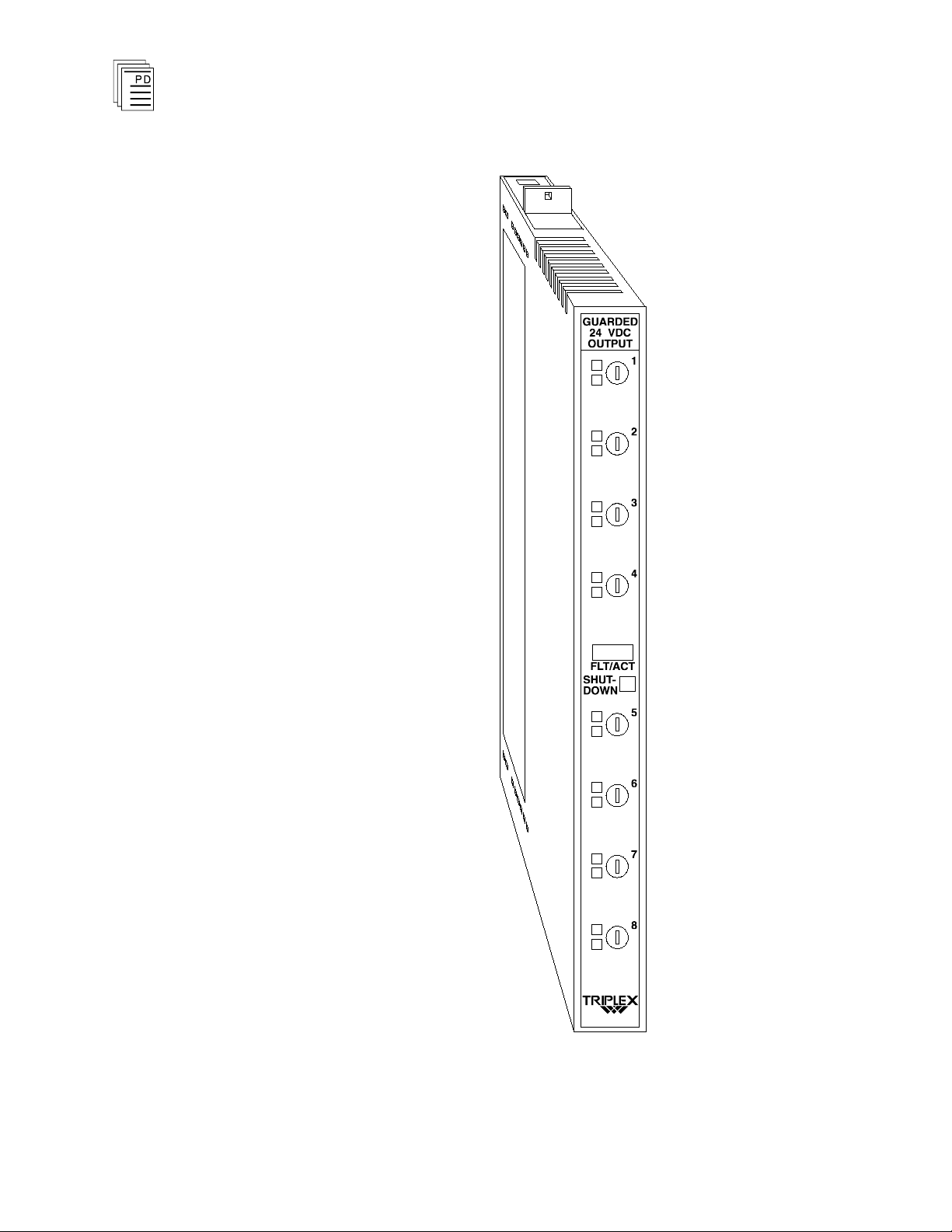
Front Panel
Figure 2 shows
output modules. The front panel of each module contains a
module active and fault status indicator, a shutdown
indicator, as well as output fuses, output status indicators, and
blown fuse indicators for each output circuit.
Active/Fault Status Indicator
These green and red LEDs indicate the overall health of the
module and its field circuits. During normal operation, the
green ACTIVE indicator flashes at the controller’s scan rate.
If a module fault is detected the red FAULT indicator turns
on and the green ACTIVE indicator turns off.
Shutdown Indicator
Upon loss of communications with the controller, output
modules enter either a shutdown or hold fault mode. If the I/O
unit is set to shutdown, the red SHUTDOWN indicator will
turn on when communications with the controller are lost. If
the I/O unit is set to hold, the SHUTDOWN indicator will
always be off (see page 13, Fault Mode Jumper).
the physical features of the DC Guarded
PD-6019
Mar-06
When the module is installed in the I/O chassis or
power (from the I/O power supply modules) is first applied to
the module, it will be in the shutdown mode until the first
output scan, regardless of the fault mode jumper settings.
Also, removing two I/O transceiver modules, two I/O power
supply modules, or two power legs will cause the module to be
in the shutdown mode.
Output Status Indicators
The output status indicators are yellow LEDs, located on the
front of the module. The state of the output circuit is sensed
on the field-side of the c
isolated to drive the logic-side LEDs. These indicators are on
when the load is energized.
5
ircuit and this status is optically
when logic
Page 6
DC Guarded Digital Output Modules (T3461A, 62A, 68A)
6
Figure 2. A DC Guarded Output Module.
Industrial Control Services
Page 7

(T3461A, 62A, 68A) DC Guarded Digital Output Modules
Applicatio
Blown Fuse Indicators
The red BLOWN FUSE indicators switch on when the
adjacent front panel fuse opens. If all four fuses in a group
have opened, all of the BLOWN FUSE indicators will switch
off and the condition will be annunciated by the module’s
FAULT indicator, which will be on.
n
Guarded digital output modules provide a suitable interface to
safety-critical output devices. These safety-critical devices
typically include solenoids, actuators, or other process
interlock outputs. Guarded output modules can be used for
fail-safe or fault tolerant operation.
Fail-Safe Configuration
As shown in Figure 3, fail-safe configuration uses a single
Guarded module. In this configuration, the worst case failure
will cause the output to fail to the off state.
In a fail-s
outputs.
Fault Tolerant Configuration
For fault tolerant operation, two Guarded modules are
connected in parallel as shown in Figure 4. In this
configuration, operation continues even if one module fails.
afe configuration, removing the module disables all
Figure 3. Fail-Safe Configuration.
PD-6019
Mar-06
7
Page 8

DC Guarded Digital Output Modules (T3461A, 62A, 68A)
In the fault tolerant configuration, a failed module can be
removed and replaced without interrupting operation of the
loads.
Figure 4. Fault Tolerant Configuration.
Fault Tolerant Configuration with Redundant Actuators
When redundant actuators are installed in the field, the level
of fault protection can be extended to include the field wiring
and actuators. Each actuator should be connected to an
individual guarded output module as shown in Figure 5.
In this configuration continuous operation can be maintained
even if a module, field wiring or load fault occu
rs.
8
Industrial Control Services
Page 9

(T3461A, 62A, 68A) DC Guarded Digital Output Modules
Figure 5. Fault Tolerant Configuration with Redundant
Field Wiring
Actuators.
Field wiring terminal blocks on the I/O chassis are used to
connect power sources and loads to the module. The terminal
blocks are located directly above and below the slot where the
module is installed. Each terminal block consists of ten #6
wire clamp screw terminals capable of holding two 12 AWG
wires.
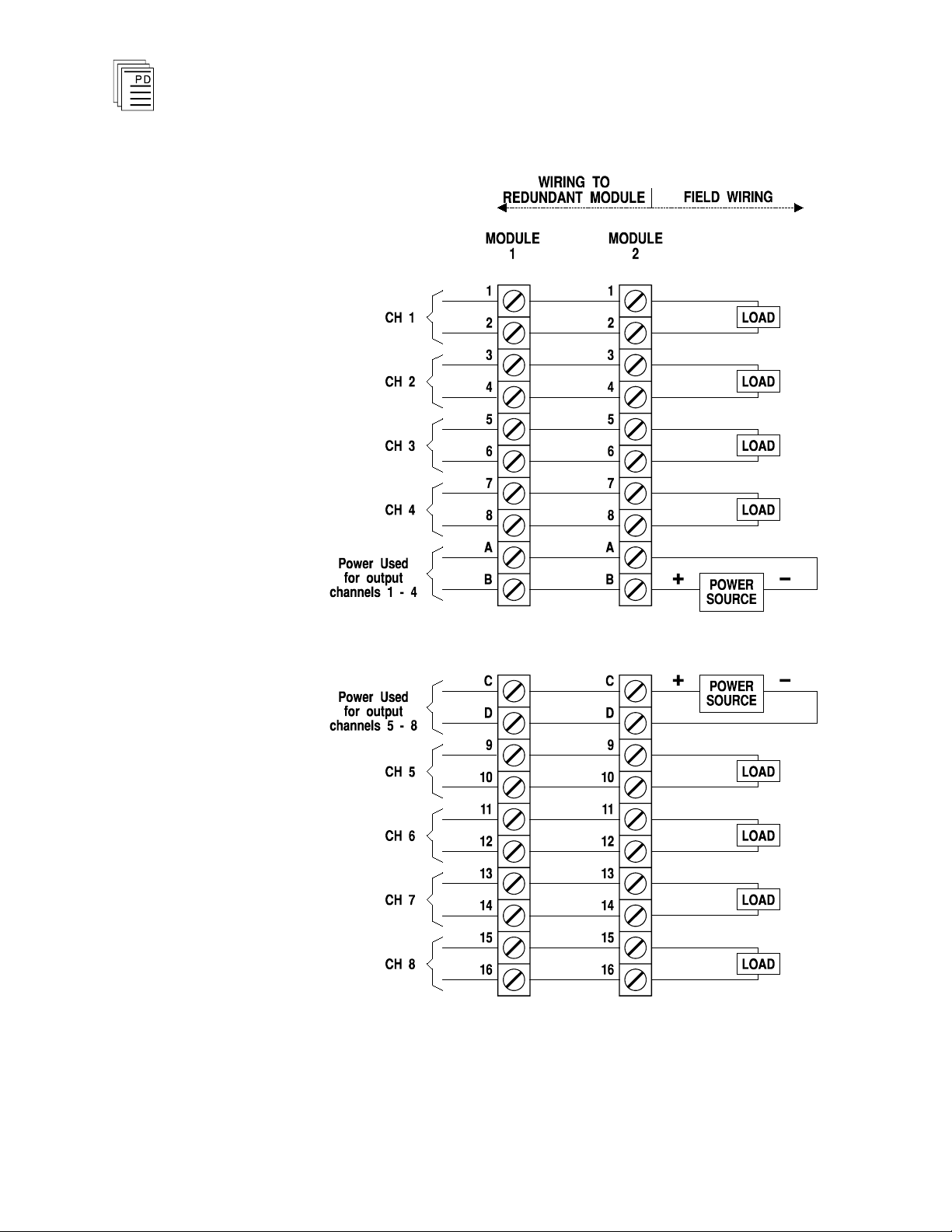
Each module has separate power terminals for each output
group (group 1: channels 1-4, group 2: channels 5-8). The two
groups are electrically isolated from each other (2500 volts
minimum). Figure 6 shows the proper field wiring for a single
module and Figure 7 shows the field wiring for fault tolerant
modules connected in parallel.
PD-6019
Mar-06
Two terminals are provided for connecting to each output load
device. When connected as shown in the field wiring
diagrams, each side of the output load is connected to the
9
Page 10

DC Guarded Digital Output Modules (T3461A, 62A, 68A)
Important!
module. In this way, the two FETs of each output circuit are
connected in series with the load: one on the positive side and
one on the negative side of the load.
The output loads must not connect to the field power supply
return out in the field. Such connection will bypass the
negative-side FET in the Guarded output and defeat the
purpose of the two series FETs for fail-safe or fault tolerant
control.
Output circuit testing requires the presence of field power on
terminals A/B and C/D. If output power is d
output testing fails and a module fault is indicated.
isconnected,
10
Industrial Control Services
Page 11

(T3461A, 62A, 68A) DC Guarded Digital Output Modules
PD-6019
Mar-06
Figure 6. Fail-Safe Field Wiring.
11
Page 12
DC Guarded Digital Output Modules (T3461A, 62A, 68A)
12
Figure 7. Fault Tolerant Field Wiring.
Industrial Control Services
Page 13

(T3461A, 62A, 68A) DC Guarded Digital Output Modules
Module
Upper
Connector
Lower
Connector
T3461A
13
2
T3462A
13
6
T3468A
13
4
Fault Mode Jumper
The fault mode jumper is located behind the ID switch cover
in the lower left-hand corner of each I/O chassis. The position
of the fault mode jumper determines the module's response to
system level faults. The fault mode jumper’s position will
cause all output modules in the I/O chassis to either shutdown
(turn off all outputs) or to hold (hold the last state) after a
system level failure occurs. An example of a system level
failure is the failure of two processor modules.
Keying
The I/O chassis can be physically keyed to prevent accidental
damage caused by inserting a module into a slot wired for a
different module type. Figure 8 illustrates how the slot keys
are installed on the I/O chassis slot field wiring connectors.
The
listed in Table 2.
slot key positions for the DC Guarded output modules are
Table 2. Slot Key Positions.
PD-6019
Mar-06
13
Page 14

DC Guarded Digital Output Modules (T3461A, 62A, 68A)
14
Figure 8. Installing Slot Keys.
Configuration
Each output module is configured using the
W
INTERPRET
I/O
Configuration Editor. In the editor you will perform the three
steps described below to configure the output module.
Industrial Control Services
Page 15

(T3461A, 62A, 68A) DC Guarded Digital Output Modules
1) Set the
Module Type:
Position the cursor on the module slot you wish to define.
Choose Set Module Type from the Edit Menu and select
the relay output module from the list.
2) Edit the Module Definition:
Choose Edit Module Definition from the Edit Menu. A
dialog box will open where you can define the output point
definitions.
Figure 9. DC Guarded Output Module Definition.
3) Edit each point:
Choose Edit from the Module Definition dialog box to
define a name and description for each output point.
the Digital Output Point dialog, enter names and values
for the configuration fields as described below.
Figure 10. Defining a Guarded Digital Output Point.
In
PD-6019
Mar-06
15
Page 16

DC Guarded Digital Output Modules (T3461A, 62A, 68A)
Name
Also called the tag name, this is the name used in the
application program to reference the output point. The name
can be up to 12 characters long.
Description
This 40-character field provides a place to describe the output
point definition. The description is used to help document
your system (it does not affect application program operation).
Comm Protect
Marking the Comm Protect check box protects the point from
changes by communications functions such as data write,
forcing, and load initial value when Comm Protect is enabled.
Initial Value
The initial value for the output is loaded to the Regent when
you load the I/O configuration and also when you load the
application program that controls the output.
Final Value
The final value for the output is loaded to the Regent when
the application program that controls the output i
s deleted.
Unless special circumstances exist, you should always enter
zero, so that the output is turned off when you delete the
application program that controls it.
Output Module Definition
In addition to configuring output point definitions, you can
configure an output module definition to represent the
combined state of all eight output points. The module
definition represents the eight output point definitions as
signed, 16-bit integers. In this format, the eight outputs are
the least significant bits with output point 1 as the LSB. The
eight most significant bits are always zero.
Programming
Outputs are controlled by writing application programs that
solve for output values. For example, placing an output tag
name on a coil in ladder logic will cause the output to turn on
when there is power flow to the coil in the ladder logic rung.
16
Industrial Control Services
Page 17

(T3461A, 62A, 68A) DC Guarded Digital Output Modules
To program fault tolerant outputs two output coils driven by
the same control logic are used as shown in Figure 11.
Maintenance
Figure 11. Programming Fault Tolerant Outputs.
In this illustration A, B, C, D represent various logic elements
used to drive the outputs; XV103A represents the output on
one Guarded output module; and XV103B represents the
output on the other Guarded output module.
No periodic maintenance or calibration is required for this
module.
Fuses can be removed and replaced without removing the
module from the I/O chassis. Turning the fuse holder one
quarter turn from its lo
extending the fuse and allowing it to be removed.
To prevent damage to the module, replacement fuses must be
of the same rating and type (see Specifications, below).
-
cked position releases the fuse holder,
Safety Considerations
The DC Guarded output modules are TÜV certified to Risk
Class 5 for safety critical outputs. The modules are approved
for de-energize to trip safety critical outputs in single or dual
module configurations.
The modules are also approved for energize to
critical outputs in dual module configuration
outputs are dynamically transitioned at a period not greater
that six months (to verify the signal wiring and load device
PD-6019
Mar-06
integrity).
trip safety
only
if the
17
Page 18

DC Guarded Digital Output Modules (T3461A, 62A, 68A)
Safetybus Power
0.85 load units
Number of Outputs
Eight circuits divided into
two groups of four circuits
each
T3461A
T3462A
T3468A
Voltage Range
18 to 30 VDC
38 to 58 VDC
95 to 150 VDC
Load Current
(0 to 40° C)
derating (at 60°
C)
1 amp
0.5 amp
0.5 amp
0.25 amp
0.5 amp
0.25 amp
(130 VDC)
0.1 amp
(150 VDC)
Minimum Load
0 mA
0 mA
0 mA
On State Drop
2.5 V,
maximum
2.5 V,
maximum
2.5 V,
maximum
Surge Current
3 amps for
20 msec
3 amps for
20 msec
3 amps for
20 msec
Output Leakage
1 mA,
maximum
1 mA,
maximum
1 mA,
maximum
Fusing
(front mounted)
One 2 amp,
250 V, fast
acting (3AB),
rectifier type,
per output
One 2 amp,
250 V, fast
acting (3AB),
rectifier type,
per output
One 2 amp, 250
V, fast acting
(3AB), rectifier
type, per
output
T
urn-On Delay
1 msec
1 msec
1 msec
Turn-Off Delay
1 msec
1 msec
1 msec
Output Test
Duration
1 msec,
maximum
1 msec,
maximum
1 msec,
maximum
Heat Dissipation
25 Watts,
87 BTUs/hour
18 Watts,
61 BTUs/hour
25 Watts,
85 BTUs/hour
Over Voltage
Protection
70 VDC,
continuous
110 VDC,
continuous
190 VDC,
continuous
Specifications
18
Industrial Control Services
Page 19

(T3461A, 62A, 68A) DC Guarded Digital Output Modules
Isolation
2500 volts minimum (field
wiring to control logic)
2500 volts minimum (output
group 1-4 to output group
5-8)
Operating Temperature
0°
to 60° C
(32° to 140° F)
Storage Temperature
-40°
to 85° C
(-40°
to 185° F)
Operating Humidity
0 to 95% relative humidity,
non-condensing
Vibration
10 to 55 Hz:
±0.15mm
Shock
Operating:
15 g, ½ sine wave, 11 msec
Electromagnetic
Interference
•
IEC 801 Part 2 - Electrostatic
Discharges
•
IEC 801 Part 3 - Radiated
Electromagnetic Fields
•
ANSI/IEEE C37.90 - Surge
Withstand Capability
Level 3: Contact discharge of
6 kV
Level 3: 10 V/M, 27 MHz 500 MHz
2.5 kV damped 1 MHz sine
wave,
4 kV bi-directional impulse,
10 nsec rise time, fast
transient
Safety
Certified to DIN V VDE
0801 for Risk Class 5. Also
designed to meet UL 508 and
CSA 22.2, No. 142-M1981
Dimensions
Height:
Width:
Depth:
12.6" (320 mm)
1.27" (32 mm)
10.12" (257 mm)
Weight
3.5 lbs (1.6 kg)
PD-6019
Mar-06
19
Page 20

DC Guarded Digital Output Modules (T3461A, 62A, 68A)
20
Industrial Control Services
 Loading...