

Page 1

ICS Regent
®
PD-6021
AC Guarded Digital Output Module
110 VAC
(T3464)
Issue 1,
AC Guarded digital output modules provide guarded
switching of user-supplied 110 AC voltages to a maximum of
sixteen field loads. These modules are called Guarded
because no single fault within a module will inadvertently
apply power to an output. Extensive fault detection and
critical redundant circuits ensure that the module operates in
a fail-safe manner.
Features
March, 06
·
Sixteen Guarded output circuits configured as two separately
powered groups of eight circuits each.
·
Fault tolerant operation when connected in parallel with
another module of the same type.
·
Hot-replace
·
100% self-test of all critical circuits.
·
Zero-cross load switching.
·
Individual front panel indicators on each module show
active/fault and output on/off status (field side). A diagnostic
message display provides additional status indicators.
·
Fuses accessible from front panel.
·
2500 volt minimum electrical isolation between field and l
circuits.
·
TÜV certified, Risk Class 5, see Safety Considerations.
Two Guarded output modules can be connected in parallel to
obtain fault tolerant control of power to loads. In this parallel
module configuration, either module can be removed and
able.
ogic
Industrial Control Services
1
Page 2
AC Guarded Digital Output Module
replaced while the other Guarded module continues to control
the loads without interruption.
(T3464)
Module Operation
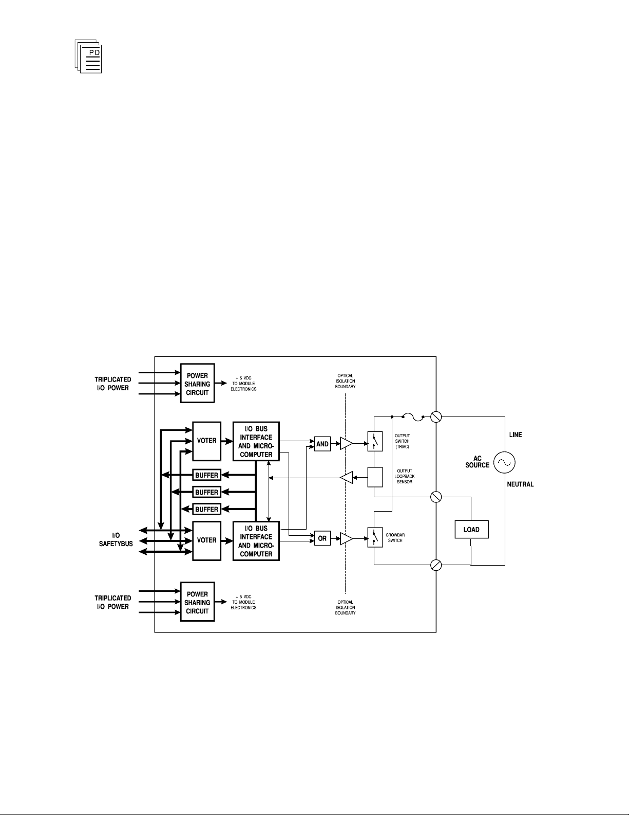
A block diagram of a typical AC Guarded digital output
module is shown in Figure 1.
The processor modules send triplicated write data commands
over the I/O Safetybus to the Guarded output module.
Onboard the Guarded output modules the triplicated data are
routed to two independent voter and microcomputer sections.
Each section independently votes the triplicated data to
generate a logic output drive signal. The two logic drive
signals are ANDed to control the output TRIAC.
2
Figure 1. Block Diagram of the AC Guarded Output Module.
The TRIAC will normally be energized only when both
microcomputer sections command the output to be on. If
either microcomputer section commands the output to be off,
Industrial Control Services
Page 3

(T3464)
AC Guarded Digital Output Module
the TRIAC will be de-energized. If the TRIAC itself fails
shorted when commanded off, either microcomputer section
can trigger an internal crowbar switch that disables the
output by blowing the fuse for that circuit.
The combination of dual independent drive signals, a TRIAC,
and a crowbar circuit provides fail-safe activation of the load
devices. No s
ingle failure can prevent the output from being
turned off when commanded. Single failures result in either
continued correct control or a fail-safe output as shown in
Table 1.
To achieve fault tolerance, two Guarded output modules are
used with their outputs connected in parallel. This
configuration provides for continued correct control even
when an output TRIAC fails open (class 2 and 5 in Table 1).
The module failure is automatically detected and th
e failed
module can be removed and replaced without interrupting
output control.
PD-6021
Mar-06
3
Page 4

Case
Commanded
Output State
Single
Failure
Actual
Output
to Load
Remarks
1 On
TRIAC
short
On
Continued correct control.
Automatic testing of crowbar
circuit ensures that output will be
able to switch off. If output is
subsequently commanded off,
crowbar switch is energized to
blow fuse and turn off output
(fuse blows 200 msec after
output is commanded off).
2 On
TRIAC
open
Off
Fail-safe output. Automatic
testing detects failed TRIAC.
3 On
Crowbar
fault
On
Continued correct control.
Automatic testing detects failed
crowbar circuit. If output is
subsequently commanded off,
TRIAC will turn off.
4
Off
TRIAC
short
200
msec
bump
A one-time, 200 msec maximum
on-state bump occurs when the
TRIAC shorts. Automatic testing
detects shorted TRIAC and
crowbar switch is activated to
blow fuse. This one-time bump
may not be suitable for certain
energize-to-trip applicatio
ns.
5
Off
TRIAC
open
Off
Fail-safe output. Automatic
testing detects failed TRIAC. If
output is subsequently
commanded on, output will
remain off.
6
Off
Crowbar
fault
Off
Continued correct control.
Automatic testing detects failed
crowbar circuit. If output is
subsequently commanded on,
TRIAC will turn on.
AC Guarded Digital Output Module
(T3464)
Table 1. Output States After Switch Failure.
4
Testing and Diagnostics
The voter and I/O bus interface logic of the Guarded output
modules is automatically tested by the processor modules.
Discrepant data are sent through one of three legs of
the I/O
Safetybus to determine whether the module’s voters are able
to outvote the incorrect data. A failure to return the correct
majority-voted result to the processors produces an I/O
Industrial Control Services
Page 5

(T3464)
AC Guarded Digital Output Module
module error indication at the processor modules and a
module fault indication at the I/O module.
Each type of module has a unique identification code that is
read by the controller. This code lets the controller know
which type of module is installed in each I/O chassis slot and
how to address that module and its points
specifically. If a
module is removed, or is replaced with a module of a different
type, the processor modules will indicate an I/O module error.
Loopback logic tests periodically write data to the module and
then read it back to determine whether the module’s I/O bus
interface logic is functioning correctly.
Fuses are periodically checked for continuity. Blown fuse
detection is independent of load connection or output circuit’s
on/off state.
Incoming AC field power is checked for proper frequency,
stabili
ty, and phase. Tests that depend on AC power timing
information, such as turn-on testing, will not execute if the AC
power is unacceptable. However, crowbar switch activation is
not dependent on these power conditions.
Approximately every 2 seconds, output circuits commanded to
be off are tested for their ability to turn on. Three test pulses
are applied on successive AC voltage phase zero crossings to
verify the output switch's ability to conduct bi-directional
current flow. The pulses are limited to 5
0 volts with a
maximum duration of 1 millisecond. This energy is
insufficient to drive most field loads.
Output TRIACs commanded to be on (output switch closed)
are not tested for their ability to turn off. Instead, the crowbar
circuit is periodically tested for its ability to turn on. If a
TRIAC fails to tuns off when commanded, either
microcomputer can energize the crowbar switch and remove
power from the load by blowing the fuse for that circuit. In
this way, an output’s inability to turn off is not discovered
until the switch is commanded to turn off. The result is a
maximum time to switch off a shorted output (blow the fuse) of
200 milliseconds.
Outputs commanded to be on are occasionally tested for open
load and open circuit (faulty output switch) conditions. If load
current is below the minimum requirements, the module tests
PD-6021
Mar-06
5
Page 6

AC Guarded Digital Output Module
the output switch's ability to conduct current (through an
internal dummy load). If current is conducted, the fault is in
the load. If no current is conducted, the fault is
switch circuit. Healthy outputs commanded to be on but not
wired to an external load will always cause an open load
condition to be displayed.
(T3464)
in the output
Front Panel
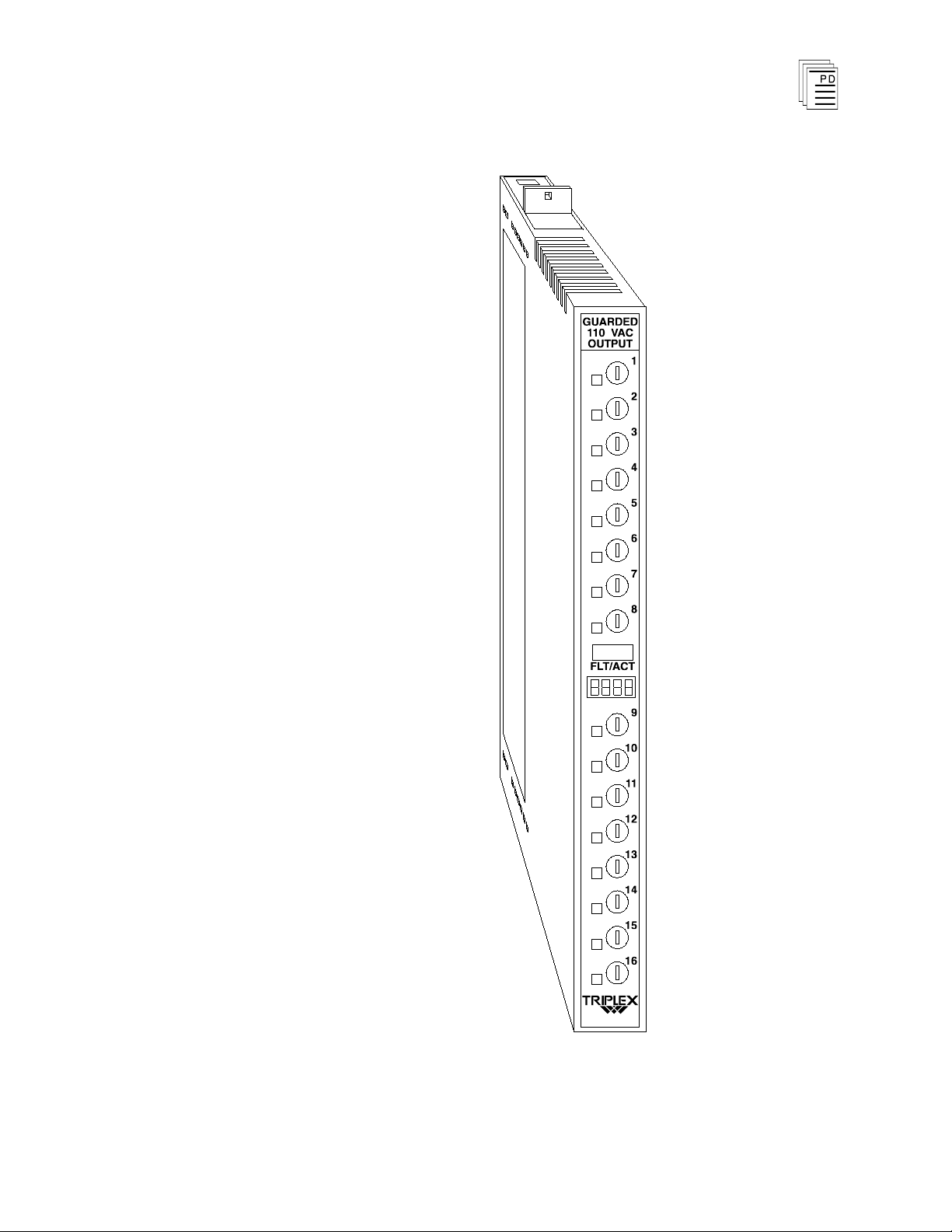
Figure 2 shows the physical features of the AC Guarded
output modules. The front panel contains an active and fault
status indicator, a diagnostic message display, as well as
status indicators and fuses for each output circuit.
Active/Fault Status Indicator
These green and red LEDs indicate the overall health o
f the
module and its field circuits. During normal operation, the
green ACTIVE indicator flashes at the controller’s scan rate.
If a module fault occurs the red FAULT indicator turns on
and the green ACTIVE indicator turns off.
Output Status Indicators
The output status indicators are yellow LEDs, located on the
field side of the output circuit, in parallel with the load. These
indicators are on when the load is energized.
6
Industrial Control Services
Page 7
(T3464)
AC Guarded Digital Output Module
PD-6021
Mar-06
Figure 2. AC Guarded Output Mod
7
ule.
Page 8

Note:
AC Guarded Digital Output Module
(T3464)
Diagnostic Message Display
This four-digit display provides additional fault diagnostics
(such as blown fuse, AC power problems, wiring faults, etc.). If
one or more fault conditions are present, the fault messages
are displayed in rotation for approximately one second each.
These fault messages are self-clearing (which means, for
example, that replacing a blown fuse will clear the blown fuse
message). However, the module’s FAULT indicator can only
be cleared by a voted reset.
Indicator messages are described in the section Maintenance,
beginning on page 18.
Shutdown Indication
Upon loss of communications with the controller, output
modules enter either a shutdown or hold fault mode. If the I/O
unit is set to shutdown, the diagnostic message display will
show Shud when communications with the controller are lost.
If the I/O unit is set to hold, diagnostic message display will
not display this message (see page 14, Fault Mode Jumper).
Application
When the module is installed in the I/O chassis or when logic
power (from the I/O power supply modules) is first applied to
the module, it will be in the shutdown mode until the first
output scan, regardless of the fault mode jumper settings.
Also, removing two I/O transceiver modules, two I/O power
supply modules, or two power legs will cause the module to be
in the shutdown mode.
Each module has separate power terminals for switch groups
1-8 and groups 9-16. The two groups are electrically isolated
from each o
difference between separate power sources cannot be
guaranteed to be less than one degree, both groups should be
wired to the same AC circuit. The microcomputers monitor
this phase difference to validate timing data derived from the
AC power.
When a crowbar circuit blows a fuse, approximately 16
additional amps of current flows through both the line and
neutral circuits until the fuse opens. Normally, only a small
ther by a minimum of 2500 volts. If the phase
8
Industrial Control Services
Page 9

(T3464)
AC Guarded Digital Output Module
current flows through the neutral wire, so it
is important to
size both the line and neutral wiring to enable them to handle
this fault current.
Modules report a open load fault when an output is
commanded on and no user load is connected. All output
circuits in service must have load connections for proper
diagnostic operation. Unused outputs can be left unconnected
so long as they are never commanded to be on. These modules
do not test for load faults when an output circuit is
commanded off.
Blown fuse detection is independent of user load connec
tion or
output circuit on/off state. However; when operating in a fault
tolerant configuration, the module will report an “OC” (open
circuit) fault instead of a “BF” (blown fuse) fault if both
outputs are on and only one of the two outputs has a blown
fuse.
The module should not be used in applications where a one
-
time 200 millisecond load bump (turn-on) cannot be tolerated.
Fail-Safe Configuration
As shown in Figure 3, the fail-safe configuration uses a single
Guarded module.
will cause the output to fail to the off state.
In this configuration, the worst case failure
In a fail-safe configuration, removing the module disables all
outputs.
PD-6021
Mar-06
Figure 3. Fail-Safe Configuration.
9
Page 10

AC Guarded Digital Output Module
(T3464)
Fault Tolerant Configuration
For fault tolerant operation, two Guarded modules are
connected in parallel as shown in Figure 4. In this
configuration, operation continues even if one module fails.
In the fault tolerant configuration, a failed module can be
removed and replaced without interrupting operation of the
loads.
Figure 4. Fault Tolerant Configuration.
Fault Tolerant Configuration with Redundant Actuators
When redundant actuators are installed in the field, the level
of fault protection can be extended to include the field wiring
and actuators. Each actuator should be connected to an
individual guarded output module as shown in Figure 5.
In this configuration continuous operation can be maintained
even if a module, field wiring or load fault occurs.
10
Industrial Control Services
Page 11

(T3464)
AC Guarded Digital Output Module
Figure 5. Fault Tolerant Configuration with Redundant
Field Wiring
Actuators.
Field wiring terminal blocks on the I/O chassis are used to
connect power sources and loads to the module. The terminal
blocks are located directly above and below the slot where the
module is installed. Each terminal block consists of ten #6
wire clamp screw terminals capable of holding two 12-AWG
wires.
Each module has separate power line and neutral terminals
for each output group (group 1: channels 1-8, group 2:
channels 9-16). The two groups are electrically isolated from
each other (2500 volts minimum). Figure 6 shows the proper
field wiring for a single module and Figure 7 shows the field
wiring for fault tolerant modules connected in parallel.
PD-6021
Mar-06
11
Page 12

AC Guarded Digital Output Module
(T3464)
12
Figure 6. Fail-Sa
fe Field Wiring.
Industrial Control Services
Page 13

(T3464)
AC Guarded Digital Output Module
PD-6021
Mar-06
Figure 7. Fault Tolerant Field Wiring.
13
Page 14

Module
Upper
Connector
Lower
Connector
T3464
17
3
AC Guarded Digital Output Module
(T3464)
Fault Mode Jumper
The fault mode jumper is located behind the ID switch cover
in the lower left-hand corner of each I/O chassis. The position
of the fault mode jumper determines the module's response to
system level faults. The fault mode jumper’s position will
cause all output modules in the I/O chassis to either shutdown
(turn off all outputs) or to hold (hold the last state) after a
system level f
failure is the failure of two processor modules.
Keying
The I/O chassis can be physically keyed to prevent accidental
damage caused by inserting a module into a slot wired for a
different module type. Figure 8 illustrates how the slot keys
are installed on the I/O chassis slot field wiring connectors.
The slot key positions for the AC Guarded output module are
listed in Table 2.
ailure occurs. An example of a system level
Table 2. Slot Key Positions.
14
Industrial Control Services
Page 15

(T3464)
AC Guarded Digital Output Module
PD-6021
Mar-06
Figure 8. Installing Slot Keys.
Configuration
Each output module is configured using the
W
INTERPRET
Configuration Editor. In the editor you will perform the three
steps described below to configure the output module.
I/O
15
Page 16

AC Guarded Digital Output Module
(T3464)
1) Set the Module Type:
Position the cursor on the module slot you wish to define.
Choose Set Module Type from the Edit Menu and select
the relay output module from the list.
2) Edit the Module Definition:
Choose Edit Module Definition from the Edit Menu. A
dialog box will open where you can define the output point
definitions.
Figure 9. AC Guarded Output Module Definition.
3) Edit each point:
Choose Edit from the Module Definition dialog box to
define a name and description for each output point. In
the Digital Output Point dialog, enter names and values
for the configuration fields as described below.
Figure 10. Defining a Guarded Digital
Output Point.
16
Industrial Control Services
Page 17

(T3464)
AC Guarded Digital Output Module
Name
Also called the tag name, this is the name used in the
application program to reference the output point. The name
can be up to 12 characters long.
Description
This 40-character field provides a place to describe the output
point definition. The description is used to help document
your system (it does not affect application program operation).
Comm Protect
Marking the Comm Protect check box protects the point from
changes by communications functions such as data write,
forcing, and load initial value when Comm Protect is enabled.
Initial Value
The initial value for the output is loaded to the Regent when
you load the I/O configuration and also when you load the
application program that controls the output.
Final Value
The final value for the output is loaded to the Regent when
the application program that controls the output is deleted.
Unless special circumstances exist, you should always enter
zero, so that the output is turned off when you delete the
application program that control
Output Module Definition
s it.
In addition to configuring output point definitions, you can
configure an output module definition to represent the
combined state of all 16 output points. The module definition
represents the 16 output point definitions as signed, 16-bit
integers. In this format, output 1 is the least significant bit
(LSB) and output point 16 is the most significant bit (MSB).
Programming
Outputs are controlled by writing application programs that
solve for output values. For example, placing an output tag
name on a coil in ladder logic will cause the output to turn on
when there is power flow to the coil in the ladder logic rung.
PD-6021
Mar-06
17
Page 18

AC Guarded Digital Output Module
To program fault tolerant outputs two output coils driven by
the same control logic are used as shown in Figure 11.
(T3464)
Maintenance
Figure 11. Programming Fault Tolerant Outputs.
In this illustration A, B, C, D represent various logic elements
used to drive the outputs; XV103A represents the output on
on
e Guarded output module; and XV103B represents the
output on the other Guarded output module.
No periodic maintenance or calibration is required for this
module.
Fuses can be removed and replaced without removing the
module from the I/O chassis. Turning the fuse holder one
quarter turn from its locked position releases the fuse holder,
extending the fuse and allowing it to be removed.
To prevent damage to the module, replacement fuses must be
of the same rating and type (see Specifications, bel
Diagnostic Messages
-
ow).
18
When the module is first inserted into an I/O chassis or when
system power is applied, the display will go through the
initialization sequence shown in Table 3.
Industrial Control Services
Page 19

(T3464)
Step Display
Description
1
8.8.8.8.
Display test. Displayed for 1 second.
2
AFO
RAM test. Displayed for 1 second. If this test
fails, the testing stops and the AFO message
remains on.
3
PF
PROM test. Displayed briefly. If this test fails
,
the testing stops and the PF message remains
on.
4
. . . . .
Normal display mode. Decimal points blink to
indicate processor activity.
5
- -
.
-
Decimal point number three should be
illuminated constantly after about 15 seconds.
This indicates the AC power source is stable
and output circuits are being tested.
AC Guarded Digital Output Module
The diagnostic messages displayed as the module operates are
used together with the module’s active and fault indicators.
A red FAULT indication on the module together with a
diagnostic message can be caused by either a power, wiring, or
load problem or by a module fault or failure.
Table 3. Initialization Sequence.
A red FAULT indication
without
a diagnostic message display
can indicate either a failed module or a fault that has already
been corrected. If the fault has been corrected, the diagnostic
message display will clear itself; however the module’s FAULT
indicator must be cleared by a voted reset. If the FAULT
indicator does not clear after a voted reset it is because the
module itself has failed and must be replaced.
PD-6021
Mar-06
19
Page 20

Display
Description
AC
AC quality problem (i.e. frequency is out of tolerance, frequency
is unstable, or phase difference between output groups 1-8 and
9-16).
AC.ab
AC power failure at field terminals A/B (output group 1-8).
AC.cd
AC power failure at field terminals C/D (output group 9-16).
Shud
Outputs are shut down (off). Caused by the loss of controller
communications or the module is not configured in the system.
Hold
Outputs are held at last stat
e. Caused by the loss of controller
communications.
BFnn
Blown fuse on output nn.
OLnn
Open load on output nn. Displayed only when output is on.
OCnn
Open circuit on output nn. Switch is not able to close.
SCnn
Short circuit on output nn. Switch is not able to open. The
crowbar switch was activated to blow the fuse. Blown fuse
message is suppressed.
Safetybus Power
1.5 load units
Number of Inputs
16 circuits divided into two
groups of eight
Voltage Range
90 to 130 VAC
Frequency Range
47 to 63 Hz
Phase Difference
1º maximum between group
1-8 and group 9-16
AC Guarded Digital Output Module
Ta
ble 4. Operating Diagnostic Messages.
(T3464)
Safety Considerations
Specifications
Although the AC Guarded output modules provide extensive
diagnostics and testing features, they have only been TÜV
certified to Risk Class 5 as non-interfering. For safety
systems that require TÜV approved equipment, the T3484
Monitored Guarded output module is recommended.
20
Industrial Control Services
Page 21

(T3464)
Load Current (maximum)
1 amp maximum per output
0°
to 40° C, derated linearly
to 0.5 amp at 60° C
16 amps maximum per
module at 0° C, derated
linearly to 8 amps at 60° C
Load Current (minimum)
Guarded mode:
Fault tolerant mode:
50 mA
150 mA
Line Current
Load current plus 16 amps
transient during crowbar
actuation
Neutral Current
16 amps maximum transient
during crowbar actuation
On State Drop
1.6 V, maximum
Surge Current
10 amps for 20 msec
Output Leakage
Guarded mode:
Fault tole
rant mode:
5 mA maximum at 60 Hz
10 mA maximum at 60 Hz
Fusing
One 2 A, 250 V, fast acting
(3AG) per output, front panel
mounted
Turn-On Delay
1 AC cycle maximum
Turn-Off Delay
1.5 AC cycle maximum
Over Voltage Protection
160 VAC, continuous
Load Bump
(Turn-on)
70 V peak for 1.1 msec,
3
pulses, repeating once per
2 seconds.
130 VAC for 200 msec, one
time for shorted output
circuit
Heat Dissipation
33 Watts, 111 BTUs/hour
AC Guarded Digital Output Module
PD-6021
Mar-06
21
Page 22

Isolation
2500 volts minimum (field
wiring to control logic)
2500 volts minimum
(output
group 1-8 to output group
9-16)
Operating Temperature
0°
to 60° C
(32° to 140° F)
Storage Temperature
-40°
to 85° C
(-40°
to 185° F)
Operating Humidity
0 to 95% relative humidity,
non-condensing
Vibration
10 to 55 Hz:
±0.15mm
Shock
Operating:
15 g, ½ sine wave, 11 msec
Electromagnetic
Interference
•
IEC 801 Part 2 - Electrostatic
Discharges
•
IEC 801 Part 3 - Radiated
Electromagnetic Fields
•
ANSI/IEEE C37.90 - Surge
Withstand Capability
Level 3: Contact discharge of
6 kV
Level 3: 10 V/M, 27 MHz 500 MHz
1 kV damped 1 MHz sine
wave
Safety
Certified to DIN V VDE
0801 for Risk Class 5, non
interfering. Also designed to
meet UL 508 and CSA 22.2,
No. 142-M1981
Dimensions
Height:
Width:
Depth:
12.6" (320 mm)
1.27" (32 mm)
10.12" (257 mm)
Weight
5.0 lbs (2.3 kg)
AC Guarded Digital Output Module
(T3464)
22
Industrial Control Services
 Loading...