

Page 1

ICS Regent
®
PD-6018
AC Isolated Digital Output Module
110 VAC
(T3454)
Issue 1,
The AC isolated digital output module provides control of
eight isolated user output loads. One type of module is
available to interface to outputs powered from isolated 110
VAC field power supplies. Each module's triplicated I/O
Safetybus interface ensures that no Regent system failure can
incorrectly apply power to an output, and that no failure in
the module can affect the operation of the Regent system or
other I/O modules in the system.
March, 06
Features
·
Eight isolated 110 VAC output circuits.
·
Hot-replaceable.
·
Automatic self-testing of triplicated I/O Safetybus circuits and
many simplex logic circuits.
·
2 amp output circuits.
·
Zero-cross load switching.
·
Individual front panel indicators on each module show active
and fault, shutdown, blown fuse, and output on/off status (logic
side).
·
2500 volt minimum e
circuits.
·
TÜV certified, Risk Class 5, non-interfering.
Module Operation
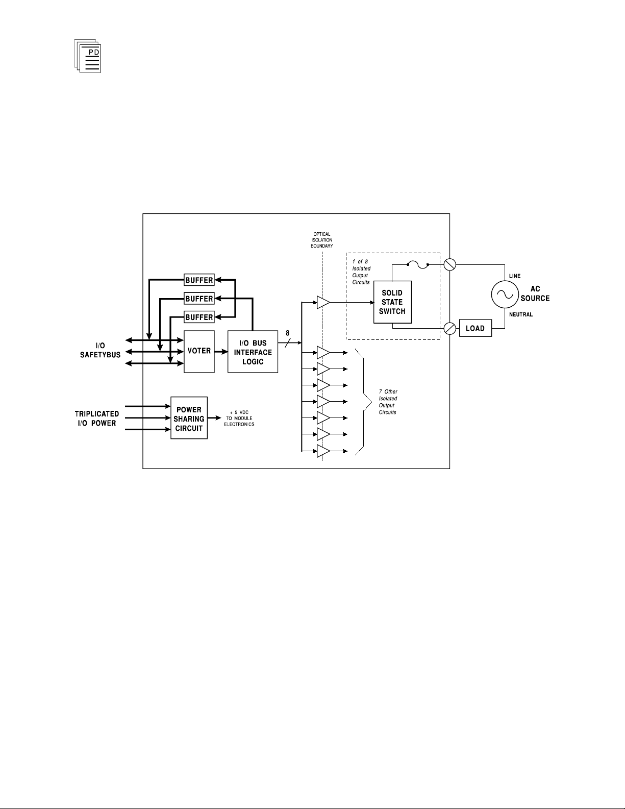
A block diagram of a typical 110 VAC isolated digital output
module is shown in Figure 1.
lectrical isolation between field and logic
Industrial Control Services
1
Page 2
AC Isolated Digital Output Module
The processor modules send triplicated write data commands
to the output module over the I/O Safetybus. The processors’
addressing data and data write commands are voted by the
module (preventing I/O Safetybus failures upstream from the
mo
dule from affecting module operation). The voted result is
then passed to the I/O bus interface logic.
(T3454)
2
Figure 1. Block Diagram of 110 VAC Isolated Digital Output Module.
The voted output data from the I/O bus interface logic is then
used to drive the output circuits. Zero crossing turn-on
TRIAC drivers are used to convert the logic level output drive
signals to switch 110 VAC power to load devices.
When the output is logically turned on, the field d
evice is
energized, and when the output is logically turned off, the
field device is de-energized.
Optical isolation between the module’s logic and field circuits
provides logic-to-field isolation
— protecting the output
module from field signal over voltages, transients, and other
electrical disturbances. It also provides a safety barrier
between the primary field voltages and user accessible
circuits. Additionally each output is isolated from the other
Industrial Control Services
Page 3

(T3454)
AC Isolated Digital Output Module
outputs, to operate load devices powered from isol
power supplies.
Each output is individually fused to protect the circuits from
short circuit conditions in output wiring and field devices.
Testing and Diagnostics
Each module’s voter circuits are periodically tested by the
processor modules. Discrepant data are sent through one of
three legs of the I/O Safetybus to determine whether the
module’s voter is able to outvote the incorrect data. A failure
to return the correct majority-voted result to the processors
produces an I/O module error indication at the processor
modules and a module fault indication at the I/O module.
Each type of module has a unique identification code that is
read by the controller. This code lets the controller know
which type of module is installed in each I/O chassis slot and
how to address that module and its points specifically. If a
module is removed, or is replaced with a module of a different
type, the processor modules will indicate an I/O module error.
ated field
Loopback logic tests periodically write data to the mo
then read it back to determine whether the module’s I/O bus
interface logic is functioning correctly.
Fuses are continually checked for continuity. Field power and
the minimum load (see Specifications, page 13) must be
connected to each output in order to detect a blown fuse.
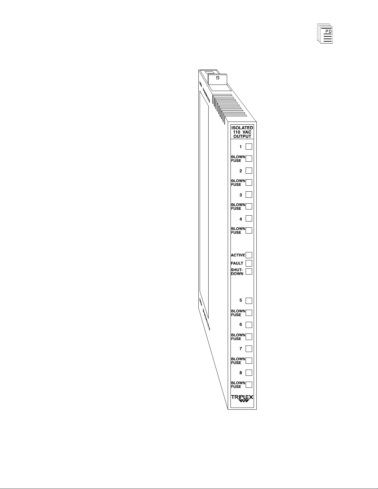
Front Panel Indicators
The 110 VAC isolated digital output module is shown in
Figure 2. The front panel contains the active and fault status
indicators, shutdown indicator
fuse indicators for each output circuit.
Active and Fault Status Indicators
These green and red LEDs indicate the overall health of the
module. During normal operation, the green ACTIVE
indicator flashes at the controller’s scan rate. If a module
fault is detected the red FAULT indicator turns on and the
green indicator turns off.
, and output status and blown
dule and
PD-6018
Mar-06
3
Page 4

Note:
AC Isolated Digital Output Module
(T3454)
Shutdown Indicator
Upon loss of communications with the controller, output
modules enter either a shutdown or hold fault mode. If the I/O
asse
mbly is set to shutdown, the red SHUTDOWN indicator
will turn on when communications with the controller are lost.
If the I/O assembly is set to hold, the SHUTDOWN indicator
will always be off (see page 8, Fault Mode Jumper).
When the module is installed in the I/O chassis or when logic
power (from the I/O power supply modules) is first applied to
the module, it will be in the shutdown mode until the first
output scan, regardless of the fault mode jumper settings.
Also, removi
ng two I/O transceiver modules, two I/O power
supply modules, or two power legs will cause the module to be
in the shutdown mode.
Output Status Indicators
The output status indicators are yellow LEDs, located on the
logic side of the output. There are 8 output status indicators
— one for each output. These indicators are lit when the
output TRIAC is energized to turn on the load.
Blown Fuse Indicators
The red BLOWN FUSE indicators turn on when the
associated output’s internal fuse opens. A blown fu
cause the module’s FAULT indicator to turn on.
se will also
The module must be connected to a load and field power must
be present to detect a blown fuse. Refer to Maintenance, page
12
, for fuse replacement instructions.
4
Industrial Control Services
Page 5
(T3454)
AC Isolated Digital Output Module
PD-6018
Mar-06
Figure 2. 110 VAC Isolated Digital Output Module.
5
Page 6

AC Isolated Digital Output Module
(T3454)
Application
Simplex Configuration
Isolated digital output modules provide a suitable interface to
non-critical output devices. These non-critical devices
typically include status alarms or other field devices that are
not used for primary safety shutdown purposes. Although
much of the circuitry on the digital output module is
automatically tested, some logic circuits and the field-side
output switch are simplex and non-tested. This simplex
configuration is illustrated in Figure 3. For safety-critical
outputs requiring fail-safe or fault tolerant output
configurations, Guarded digital output modules should be
used.
6
Figure 3. Simplex Digital Output Configuration.
Field Wiring
Field wiring terminal blocks on the I/O chassis are used to
connect power sources and loads to the module. The terminal
blocks are located directly above and below the slot where the
module is installed. Each terminal block consists of ten #6
wire clamp screw terminals capable of holding two 12 AWG
wires.
Each output has two terminals for connecting to an isolated
power source and to the output load. E
electrically isolated from the others by a minimum of 2500
volts. Figure 4 shows the proper field wiring connections for
the isolated digital output module.
ach output is
Industrial Control Services
Page 7

(T3454)
AC Isolated Digital Output Module
PD-6018
Mar-06
Figure 4. Module Wiring.
7
Page 8

Module
Upper
Connector
Lower
Connector
T3454
16
2
AC Isolated Digital Output Module
(T3454)
Fault Mode Jumper
The fault mode jumper is located behind the ID switch cover
in the lower left-hand corner of each I/O chassis. The position
of the fault mode jumper determines the module's response to
system level faults. The fault
cause all output modules in the I/O chassis to either shutdown
(turn off all outputs) or to hold (hold the last state) after a
system level failure occurs. An example of a system level
failure is the failure of two processor modules.
Keying
The I/O chassis can be physically keyed to prevent accidental
damage caused by inserting a module into a slot wired for a
different module type. Figure 5 illustrates how the slot keys
are installed on the I/O chassis
The slot key positions for the AC isolated digital output
module are listed in Table 1.
mode jumper’s position will
slot field wiring connectors.
Table 1. Slot Key Positions.
8
Industrial Control Services
Page 9

(T3454)
AC Isolated Digital Output Module
PD-6018
Mar-06
Figure 5. Installing Slot Keys.
Configuration
Each output module is configured using the
W
INTERPRET
I/O
Configuration Editor. In the editor you will perform the three
steps described below to config
9
ure the output module.
Page 10

AC Isolated Digital Output Module
(T3454)
1) Set the Module Type:
Position the cursor on the module slot you wish to define.
Choose Set Module Type from the Edit Menu and select
the appropriate digital output module from the list.
2) Edit the Module Definition:
Choose Edit Module Definition from the Edit Menu. A
dialog box will open where you can define the output point
definitions.
Figure 6. Digital Output Module Definition.
3) Edit each point:
Choose Edit from the Module Definition dialog box to
define a name and description for each output point. In
the Digital Output Point dialog, enter names and values
for the configuration fields as described below.
Figure 7. Defining a Digital Output Point.
10
Industrial Control Services
Page 11

(T3454)
AC Isolated Digital Output Module
Name
Also called the tag name, this is the name used in the
application program to reference the output point. The name
can be up to 12 characters long.
Description
This 40-character field provides a place to describe the output
point definition. The description is used to help document
your system (it does not affect application program operation).
Comm Protect
Marking the Comm Protect check box protects the point from
changes by communications functions such as data write,
forcing, and load initial value when Comm Protect is enabled.
Initial Value
The initial value for the output is loaded to the Regent when
you load the I/O configuration and also when you load the
application program that controls the output.
Final Value
The final value for the output is loaded to the Regent
when
the application program that controls the output is deleted.
Unless special circumstances exist, you should always enter
zero, so that the output is turned off when you delete the
application program that controls it.
Output Module Definition
In addition to configuring output point definitions, you can
configure an output module definition to represent the
combined state of all eight output points. The module
definition represents the eight output point definitions as
signed, 16-bit integers. In
this format, the eight outputs are
the least significant bits with output point 1 as the LSB. The
eight most significant bits are always zero.
Programming
Outputs are controlled by writing application programs that
solve for output values. For example, placing an output tag
name on a coil in ladder logic will cause the output to turn on
when there is power flow to the coil in the ladder logic rung.
You can also reference the logic state of the output in your
PD-6018
Mar-06
11
Page 12

AC Isolated Digital Output Module
(T3454)
Maintenance
control logic by using a contact element (or
with the output point name.
similar element)
No periodic maintenance or calibration is required for this
module.
Fuses for each output are located within the module. To
replace a blown fuse the output module must be removed from
the I/O chassis and opened. To open the output module,
remove four screws from the side of the module’s clamshell.
Remove the blown fuse from its retaining clips (on the circuit
board) and replace it.
To prevent damage to the module, replacement fuses must be
of
the same rating and type (see Specifications, below).
To prevent electrostatic damage to sensitive module circuits,
maintenance personnel should always use the proper anti
static work areas and grounding straps when handling or
working with circuit boards.
-
Safety Considerations
The AC isolated digital output module is TÜV certified as
non-interfering, and can be used in a safety system for
simplex non-safety critical outputs. For safety critical
outputs, guarded output modules should be used (model
T3484 or T3485 are recommended).
12
Industrial Control Services
Page 13

(T3454)
Safetybus Power
0.75 load units
Number of Outputs
8 circuits, individually
isolated
Voltage Range
90 to 130 VAC
Frequency Range
47 to 63 Hz
Load Current
2 amps maximum per output
0°
to 60° C
16 amps maximum per
module 0° to 40° C, derated
linearly to 12 amps at 60° C
Minimum Load
50 mA
On S
tate Drop
2.0 volts maximum
Surge Current
15 amps, 20 msec
Output Leakage
2.5 mA maximum
Fusing
One 3 A, 250 V, fast-acting
(3AG) per output, located
inside module
Turn-On Delay
½ AC cycle, maximum
Turn-Off Delay
½ AC cycle, maximum
Heat Dissipation
32 Watts, 107 BTUs/hour
Over Voltage Protection
275 VAC, continuous
Isolation
2500 volts minimum (field
wiring to control logic)
2500 volts minimum
(channel to channel)
Operating Temperature
0°
to 60° C
(32° to 140° F)
Storage Temperature
-40°
to 85° C
(-40°
to 185° F)
AC Isolated Digital Output Module
Specifications
PD-6018
Mar-06
13
Page 14

Operating Humidity
0 to 95% relative humidity,
non-condensing
Vibration
10 to 55 Hz:
±0.15mm
Shock
Operating:
15 g, ½ sine wave, 11 msec
Electromagnetic
Interference
•
IEC 801 Part 2 - Electrostatic
Disc
harges
•
IEC 801 Part 3 - Radiated
Electromagnetic Fields
•
ANSI/IEEE C37.90 - Surge
Withstand Capability
Level 3: Contact discharge of
6 kV
Level 3: 10 V/M, 27 MHz 500 MHz
1 kV damped 1 MHz sine
wave
Safety
Certified to DIN V VDE
0801 (non-interfering) and
designed to meet UL 508 and
CSA 22.2, No. 142-M1981
Dimensions
Height:
Width:
Depth:
12.6" (320 mm)
1.27" (32 mm)
10.12" (257 mm)
Weight
4.0 lbs (1.8 kg)
AC Isolated Digital Output Module
(T3454)
14
Industrial Control Services
 Loading...