

Page 1
Reference Manual
Rockwell Automation Library of Process Objects:
PowerFlex 6000 Drive (P_PF6000)
IMPORTANT
This manual applies to the Rockwell Automation Library of Process Objects version 3.5 or earlier.
For Rockwell Automation Library of Process Objects version 5.0, see
• PROCES-RM200
For Rockwell Automation Library of Process Objects version 4.0 or later, use the following manuals:
• PROCES-RM013 contains logic instructions
• PROCES-RM014 contains display elements
Page 2
Important User Information
IMPORTANT
Read this document and the documents listed in the additional resources section about installation, configuration, and
operation of this equipment before you install, configure, operate, or maintain this product. Users are required to
familiarize themselves with installation and wiring instructions in addition to requirements of all applicable codes, laws,
and standards.
Activities including installation, adjustments, putting into service, use, assembly, disassembly, and maintenance are required
to be carried out by suitably trained personnel in accordance with applicable code of practice.
If this equipment is used in a manner not specified by the manufacturer, the protection provided by the equipment may be
impaired.
In no event will Rockwell Automation, Inc. be responsible or liable for indirect or consequential damages resulting from the
use or application of this equipment.
The examples and diagrams in this manual are included solely for illustrative purposes. Because of the many variables and
requirements associated with any particular installation, Rockwell Automation, Inc. cannot assume responsibility or
liability for actual use based on the examples and diagrams.
No patent liability is assumed by Rockwell Automation, Inc. with respect to use of information, circuits, equipment, or
software described in this manual.
Reproduction of the contents of this manual, in whole or in part, without written permission of Rockwell Automation,
Inc., is prohibited.
Throughout this manual, when necessary, we use notes to make you aware of safety considerations.
WARNING: Identifies information about practices or circumstances that can cause an explosion in a hazardous environment,
which may lead to personal injury or death, property damage, or economic loss.
ATTENTION: Identifies information about practices or circumstances that can lead to personal injury or death, property
damage, or economic loss. Attentions help you identify a hazard, avoid a hazard, and recognize the consequence.
Identifies information that is critical for successful application and understanding of the product.
Labels may also be on or inside the equipment to provide specific precautions.
SHOCK HAZARD: Labels may be on or inside the equipment, for example, a drive or motor, to alert people that dangerous
voltage may be present.
BURN HAZARD: Labels may be on or inside the equipment, for example, a drive or motor, to alert people that surfaces may
reach dangerous temperatures.
ARC FLASH HAZARD: Labels may be on or inside the equipment, for example, a motor control center, to alert people to
potential Arc Flash. Arc Flash will cause severe injury or death. Wear proper Personal Protective Equipment (PPE). Follow ALL
Regulatory requirements for safe work practices and for Personal Protective Equipment (PPE).
Allen-Bradley, ControlLogix, FactoryTalk, Logix5000, PlantPAx, PowerFlex, Rockwell Automation, Rockwell Software, RSL ogix, and Studio 5000 Log ix Designer are trademarks of Rockwell Automation, Inc.
Trademarks not belonging to Rockwell Automation are property of their respective companies.
Page 3

Table of Contents
Preface
Software Compatibility . . . . . . . . . . . . . . . . . . . . . . . . . . . . . . . . . . . . . . . . . 5
Additional Resources . . . . . . . . . . . . . . . . . . . . . . . . . . . . . . . . . . . . . . . . . . . 5
PowerFlex 6000 Drive (P_PF6000) Guidelines . . . . . . . . . . . . . . . . . . . . . . . . . . . . . . . . . . . . . . . . . . . . . . . . . . . . . 7
Functional Description . . . . . . . . . . . . . . . . . . . . . . . . . . . . . . . . . . . . . . . . . 8
Required Files. . . . . . . . . . . . . . . . . . . . . . . . . . . . . . . . . . . . . . . . . . . . . . . . . . 9
Controller File . . . . . . . . . . . . . . . . . . . . . . . . . . . . . . . . . . . . . . . . . . . . . 9
Visualization Files . . . . . . . . . . . . . . . . . . . . . . . . . . . . . . . . . . . . . . . . . . 9
Controller Code . . . . . . . . . . . . . . . . . . . . . . . . . . . . . . . . . . . . . . . . . . . . . . 12
PowerFlex Drive InOut Structure. . . . . . . . . . . . . . . . . . . . . . . . . . . 12
PowerFlex 6000 Drive Input Structure . . . . . . . . . . . . . . . . . . . . . . 14
PowerFlex 6000 Drive Output Structure . . . . . . . . . . . . . . . . . . . . 19
PowerFlex 6000 Drive Local Configuration Tags. . . . . . . . . . . . . 23
Operations . . . . . . . . . . . . . . . . . . . . . . . . . . . . . . . . . . . . . . . . . . . . . . . . . . . 25
Modes . . . . . . . . . . . . . . . . . . . . . . . . . . . . . . . . . . . . . . . . . . . . . . . . . . . . 25
Alarms. . . . . . . . . . . . . . . . . . . . . . . . . . . . . . . . . . . . . . . . . . . . . . . . . . . . 26
Simulation . . . . . . . . . . . . . . . . . . . . . . . . . . . . . . . . . . . . . . . . . . . . . . . . 27
Execution. . . . . . . . . . . . . . . . . . . . . . . . . . . . . . . . . . . . . . . . . . . . . . . . . 27
Programming Example . . . . . . . . . . . . . . . . . . . . . . . . . . . . . . . . . . . . . . . . 28
Display Elements. . . . . . . . . . . . . . . . . . . . . . . . . . . . . . . . . . . . . . . . . . . . . . 31
State Indicators . . . . . . . . . . . . . . . . . . . . . . . . . . . . . . . . . . . . . . . . . . . 34
Status/Quality Indicators . . . . . . . . . . . . . . . . . . . . . . . . . . . . . . . . . . 34
Mode Indicators. . . . . . . . . . . . . . . . . . . . . . . . . . . . . . . . . . . . . . . . . . . 36
Alarm Indicators . . . . . . . . . . . . . . . . . . . . . . . . . . . . . . . . . . . . . . . . . . 37
Maintenance Bypass Indicator . . . . . . . . . . . . . . . . . . . . . . . . . . . . . . 37
Using Display Elements . . . . . . . . . . . . . . . . . . . . . . . . . . . . . . . . . . . . 38
Quick Display . . . . . . . . . . . . . . . . . . . . . . . . . . . . . . . . . . . . . . . . . . . . . . . . 39
Faceplate . . . . . . . . . . . . . . . . . . . . . . . . . . . . . . . . . . . . . . . . . . . . . . . . . . . . . 40
Operator Tab . . . . . . . . . . . . . . . . . . . . . . . . . . . . . . . . . . . . . . . . . . . . . 40
Maintenance Tab. . . . . . . . . . . . . . . . . . . . . . . . . . . . . . . . . . . . . . . . . . 45
Engineering Tab. . . . . . . . . . . . . . . . . . . . . . . . . . . . . . . . . . . . . . . . . . . 49
Diagnostics Tab . . . . . . . . . . . . . . . . . . . . . . . . . . . . . . . . . . . . . . . . . . . 56
Trends Tab . . . . . . . . . . . . . . . . . . . . . . . . . . . . . . . . . . . . . . . . . . . . . . . 57
Alarms Tab . . . . . . . . . . . . . . . . . . . . . . . . . . . . . . . . . . . . . . . . . . . . . . . 58
PowerFlex Drive Faceplate Help . . . . . . . . . . . . . . . . . . . . . . . . . . . . 60
Rockwell Automation Publication SYSLIB-RM057A-EN-P - January 2017 3
Page 4

Table of Contents
Notes:
4 Rockwell Automation Publication SYSLIB-RM057A-EN-P - January 2017
Page 5

Preface
This manual describes the Add-On Instruction that controls and monitors a
PowerFlex® 6000 Medium Voltage Variable Frequency Drive.
Software Compatibility
Additional Resources
For the latest compatible software information and to download the Rockwell
Automation® Library of Process Objects, see the Product Compatibility and
Download Center at
http://www.rockwellautomation.com/rockwellautomation/support/pcdc.page
For general library considerations, see Rockwell Automation Library of Process
Objects, publication PROCES-RM002
.
These documents contain additional information concerning related products
from Rockwell Automation.
Table 1 - Additional Resources
Resource Description
PlantPAx® Distributed Control System Selection Guide,
publication PROCES-SG001
PlantPAx Distributed Control System Reference Manual,
publication PROCES-RM001
Rockwell Automation Library of Process Objects,
publication PROCES-RM002
FactoryTalk® View Machine Edition User Manual,
publication VIEWME-UM004
FactoryTalk View Site Edition User Manual,
publication VIEWSE-UM006
PowerFlex 6000 Medium Voltage Variable Frequency Drive
Parameter Manual, publication 6000-TD004
Rockwell Automation Library of Process Objects: Common
Alarm Block (P_Alarm) Reference Manual, publication
SYSLIB-RM002
Rockwell Automation Library of Process Objects: Interlocks
with First Out and Bypass (P_Intlk) Reference Manual,
publication SYSLIB-RM004
Rockwell Automation Library of Process Objects: Common
Mode Block (P_Mode) Reference Manual, publication
SYSLIB-RM005
Rockwell Automation Library of Process Objects: Permissives
with Bypass (P_Perm) Reference Manual, publication
SYSLIB-RM007
Provides information to assist with equipment
procurement for your PlantPAx system.
Provides characterized recommendations for
implementing your PlantPAx system.
Provides general considerations for the PlantPAx system
library of process objects.
Provides details on how to use this software package for
creating an automation application.
Provides details on how to use this software package for
developing and running human-machine interface
(HMI) applications that can involve multiple users and
servers, distributed over a network.
Provides details regarding functions, parameters, and
troubleshooting information for medium voltage
PowerFlex 6000 drives.
Details how to monitor an input condition to raise an
alarm. Information includes acknowledging, resetting,
inhibiting, and disabling an alarm. Generally the
P_Alarm faceplate is accessible from the Alarms tab.
Explains how to collect (sum up) the interlock
conditions that stop or de-energize a running or
energized piece of equipment or prevent it from
starting or being energized.
Explains how to choose the Mode (owner) of an
instruction or control strategy. The Mode instruction is
usually embedded within other instructions to extend
their functionality.
Details how to collect permissive conditions to start a
piece of equipment.
.
Rockwell Automation Publication SYSLIB-RM057A-EN-P - January 2017 5
Page 6

Preface
Table 1 - Additional Resources
Resource Description
Rockwell Automation Library of Process Objects: Restart
Inhibit for Large Motor (P_ResInh) Reference Manual,
publication SYSLIB-RM009
Rockwell Automation Library of Process Objects: Run Time
and Starts (P_RunTime) Reference Manual, publication
SYSLIB-RM010
Explains how to protect a large motor from damage
caused by repeated starts.
Explains how to accumulate the total run time and
count of starts for a motor or other equipment.
6 Rockwell Automation Publication SYSLIB-RM057A-EN-P - January 2017
Page 7
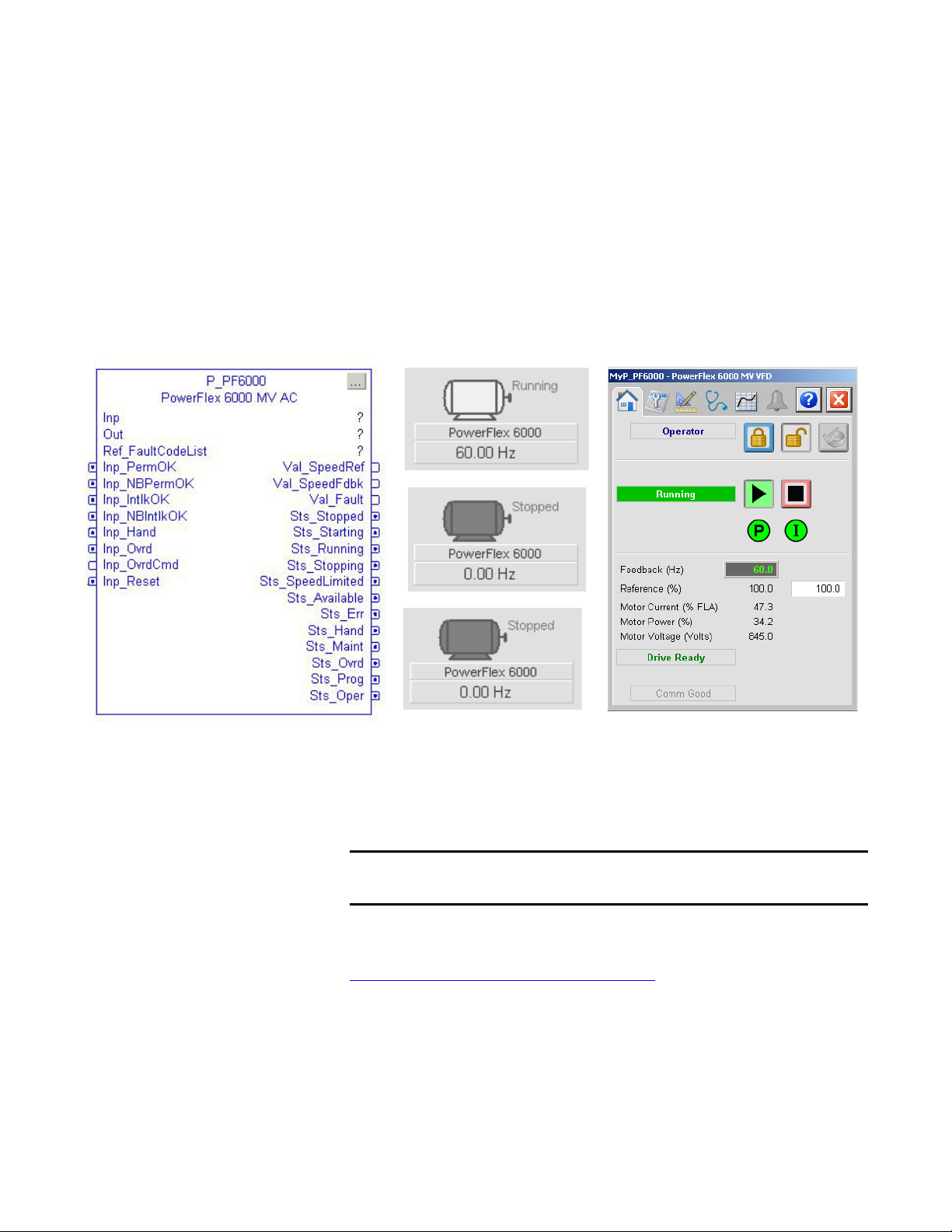
PowerFlex 6000 Drive (P_PF6000)
Add-On Instruction FaceplateGlobal Objects
IMPORTANT
The P_PF6000 (PowerFlex 6000 drive) object is used to operate one
variable-speed motor by using a PowerFlex 6000 medium voltage variable
frequency AC drive. The drive operates via an add-on EtherNet/IP interface.
The Add-On Instruction controls the drive in various modes and monitors fault
conditions. The global objects and faceplate that is shown are examples of the
graphical interface tools for this instruction.
Guidelines
This instruction operates a motor connected to a PowerFlex 6000 variable
frequency AC drive, which is communicating with the controller over an
EtherNet/IP network.
The PowerFlex 6000 drive has specific parameter read/write functionality. For
details, see Knowledgebase Answer ID 1008677 at
https://www.rockwellautomation.custhelp.com
Do not use this instruction in these situations:
• You need to operate a single-speed motor (running and stopped only). Use
• You need to operate a two-speed motor (fast, slow, and stopped only). Use
Rockwell Automation Publication SYSLIB-RM057A-EN-P - January 2017 7
The drive interface is designed to work with the Studio 5000 Logix Designer®
application, Version 20 and later.
.
the P_Motor instruction instead.
the P_Motor2Spd instruction instead.
Page 8

PowerFlex 6000 Drive (P_PF6000)
• You need to operate a simple reversing motor (forward, reverse, and
stopped only). Use the P_MotorRev instruction instead.
• You need to operate a motor with multiple discrete speeds. You need
specific logic for this motor. The P_PF6000 instruction is designed for
motors with continuously variable (analog) speed, not multiple discrete
speed selections. You can use the P_D4SD or P_nPos instruction for
motors with multiple discrete speeds.
• You are using a drive other than the PowerFlex 6000 drive. Instead, use
these Add-On Instructions:
– P_PF52x for the PowerFlex 523 or PowerFlex 525 drive on an
EtherNet/IP network
– P_PF753 for the PowerFlex drive with 20-COMM-E EtherNet/IP
Interface
– P_PF755 for the PowerFlex AC variable frequency drive
– P_PF7000 for the PowerFlex 7000 medium voltage AC variable
frequency drive with 20-COMM-E EtherNet/IP interface.
– P_VSD for third-party drives, drives on other networks, or via
hardwired I/O
Functional Description
The P_PF6000 instruction provides the following capabilities:
• Ownership of the drive through the standard P_Mode Add-On
Instruction and modes.
• Ability to start and stop the drive and motor, control the drive speed (via
speed reference), and monitor the drive run status and speed feedback to
verify whether the drive is running or stopped. Provides alarms and drive
shutdown for Fail to Start and Fail to Stop if the feedback does not follow
the commanded state within a configured amount of time.
• Reading from the drive, the instruction displays drive faults, general drive
status data, and a number of operating parameters.
• Ability to read fault data from the drive and provide descriptive text with
fault codes.
• Indication of Warning or Alarm status as received from the drive.
• Input and alarm for a drive fault condition and an output to send a drive
fault reset to the drive. Provide a configurable time to pulse the drive fault
reset output when a reset command is received.
• Permissives (bypassable and non-bypassable) that are conditions that
enable a drive start and Interlocks (bypassable and non-bypassable) that are
conditions that stop the drive and help prevent starting. Provide an alarm
when an Interlock stops the drive. Provide maintenance the capability to
bypass the bypassable Permissives and Interlocks.
8 Rockwell Automation Publication SYSLIB-RM057A-EN-P - January 2017
Page 9

PowerFlex 6000 Drive (P_PF6000)
IMPORTANT
• Maintenance personnel can disable (soft lock out) the drive. This
capability is not a substitute for hard lockout/tagout (LOTO) procedures.
• Monitor an I/O fault input and a communication watchdog timer, and
alarm on an I/O or communication failure. The failure condition can
optionally de-energize the outputs to the drive, requiring a reset.
• In Override mode, provide an override state input that determines if the
override is to run or stop the drive (default = stop), and, if the drive is to
run, an override speed reference and direction.
• The instruction provides simulation capability. Outputs to the drive are
kept de-energized, but the object can be manipulated as if a working drive
were present, including a basic ramp-up of speed feedback value on
starting and ramp-down on stopping. The simulated ramp-up-to-speed
time is configurable. This capability is often used for activities such as
system testing and operator training.
Required Files
Add-On Instructions are reusable code objects that contain encapsulated logic
that can streamline implementing your system. This functionality lets you create
your own instruction set for programming logic as a supplement to the
instruction set provided natively in the ControlLogix® firmware. An Add-On
Instruction is defined once in each controller project, and can be instantiated
multiple times in your application code as needed.
Controller File
The P_PF6000_3_5-00_RUNG.L5X rung import must be imported into the
controller project to be used in the controller configuration. The service release
number (boldfaced) can change as service revisions are created.
Visualization Files
This Add-On Instruction has associated visualization files that provide a
common user interface. These files can be downloaded from the Product
Compatibility and Download Center at
http://www.rockwellautomation.com/rockwellautomation/support/pcdc.page
The visualization file dependencies require Process Library content imports to
occur in a specific order as reflected in the following tables:
• Images
• Global Objects
• Standard Displays
• HMI Tags
• Macros
.
Images are external graphic files that can be used in displays. They must be
imported for FactoryTalk View software to make use of them.
Rockwell Automation Publication SYSLIB-RM057A-EN-P - January 2017 9
Page 10
PowerFlex 6000 Drive (P_PF6000)
When PNG files are imported, they are renamed by FactoryTalk View software
with a .bmp file extension, but retain a .png format.
Table 2 - Visualization Files: Images (.png)
FactoryTalk View SE Software FactoryTalk View ME Software Description
All .png files in the images folder All .png files in the images folder These are the common icons that are used in the global
objects and standard displays for all Process Objects.
The Global Object files (.ggfx file type) in the following table are Process Library
display elements that are created once and referenced multiple times on multiple
displays in an application. When changes are made to a Global Object, all
instances in the application are automatically updated.
Table 3 - Visualization Files: Global Objects (.ggfx)
FactoryTalk View SE Software FactoryTalk View ME Software Description
(RA-BAS) Common Faceplate Objects (RA-BAS-ME) Common Faceplate Objects Global objects used on process object faceplates.
(RA-BAS) P_VSD Graphics Library (RA-BAS-ME) P_VSD Graphics Library Drive global object device symbols used to build
(RA-BAS) Process Alarm Objects (RA-BAS-ME) Process Alarm Objects Global objects used for managing alarms on process
(RA-BAS) Process Diagnostic Objects (RA-BAS-ME) Process Diagnostic Objects Diagnostic global objects used on process
(RA-BAS) Process Faceplate Motor Objects (RA-BAS-ME) Process Faceplate Motor Objects Motor global objects used on process object faceplates.
(RA-BAS) Process Help Objects (RA-BAS-ME) Process Help Objects Global objects used for all process objects help displays.
(RA-BAS) Process Interlock Objects (RA-BAS-ME) Process Interlock Objects Global objects used for managing interlocks and
(RA-BAS) Process Mode Objects (RA-BAS-ME) Process Mode Objects Global objects used for managing modes on process
process graphics.
object faceplates.
object faceplates.
permissives on process object faceplates.
object faceplates.
The Standard Display files (.gfx file type) in the following table are the Process
Library displays that you see at runtime.
Table 4 - Visualization Files: Standard Displays (.gfx)
FactoryTalk View SE Software FactoryTalk View ME Software Description
(RA-BAS) Common-AnalogEdit N/A Faceplate used for analog input data entry. The FactoryTalk
(RA-BAS) P_Alarm-Faceplate (RA-BAS-ME) P_Alarm-Faceplate The faceplate that is used for the object
(RA-BAS) P_Alarm-Help (RA-BAS-ME) P_Alarm-Help Alarm Help information that is accessed from the
(RA-BAS) P_Mode-Config (RA-BAS-ME) P_Mode-Config The Configuration Display used to configure the
(RA-BAS) P_Mode-Help (RA-BAS-ME) P_Mode-Help Mode Help information that is accessed from the
(RA-BAS) P_PF6000-Faceplate (RA-BAS-ME) P_PF6000-Faceplate The faceplate display that is used for the object
(RA-BAS) P_PF6000-Quick (RA-BAS-ME) P_PF6000-Quick The Quick display that is used for the object
(RA-BAS) Process Motor Family-Help (RA-BAS-ME) Process Motor Family-Help The Help display for Motor objects
View ME faceplates use the native analog input data entry
so no file is required.
P_AIarm faceplate.
P_Mode object.
Help faceplate.
10 Rockwell Automation Publication SYSLIB-RM057A-EN-P - January 2017
Page 11

Table 4 - Visualization Files: Standard Displays (.gfx)
FactoryTalk View SE Software FactoryTalk View ME Software Description
(RA-BAS) P_Intlk-Faceplate (RA-BAS-ME) P_Intlk-Faceplate Optional
The interlock faceplate used for the object.
Use this file if your Discrete Output has an associated
P_Intlk object and you enable navigation to its faceplate
from the Discrete Output faceplate.
(RA-BAS) P_Perm-Faceplate (RA-BAS-ME) P_Perm-Faceplate Optional
Permissive faceplate that is used for the object
Use this file if your object has an associated P_Perm object
and you enable navigation to the P_Perm faceplate from
the object faceplate.
(RA-BAS) P_ResInh-Faceplate (RA-BAS-ME) P_ResInh-Faceplate Optional
Restart/inhibit faceplate display that is used for the object
Use this file if your object has an associated P_ResInh
object and you enable navigation to the P_ResInh
faceplate from the object faceplate.
(RA-BAS) P_RunTime-Faceplate (RA-BAS-ME) P_RunTime-Faceplate Optional
RunTime faceplate display that is used for the object
Use this file if your object has an associated P_RunTime
object and you enable navigation to the P_RunTime
faceplate from the object faceplate.
(RA-BAS) Process Interlock Family-Help (RA-BAS-ME) Process Interlock Family-Help Optional
Interlock/permissives help display that is used for
the object
Use this file if you use the P_Intlk or P_Perm faceplate.
PowerFlex 6000 Drive (P_PF6000)
HMI Tags are created in a FactoryTalk View ME application to support tab
switching on Process Library faceplates. The HMI tags can be imported via the
comma-separated values file (.csv file type) in the following table.
Table 5 - Visualization Files: HMI Tags (.csv)
FactoryTalk View SE Software FactoryTalk View ME Software Description
N/A FTVME_PlantPAxLib_Tags_3_5_xx.csv
where xx = the service release number.
These tags must be imported into the
FactoryTalk View ME project to support switching tabs on
any Process Object faceplate.
Rockwell Automation Publication SYSLIB-RM057A-EN-P - January 2017 11
Page 12
PowerFlex 6000 Drive (P_PF6000)
TIP
Controller Code
This section describes the parameter references for this Add-On Instruction.
PowerFlex Drive InOut Structure
InOut parameters are used to link the Add-On Instruction to external tags that
contain necessary data for the instruction to operate. These external tags must be
of the data type shown.
Table 6 - P_PF6000 Drive InOut Parameters
Tag Name Data Type Description
Inp P_PF6000_Inp PowerFlex 6000 input assembly.
Out P_PF6000_Out PowerFlex 6000 output assembly.
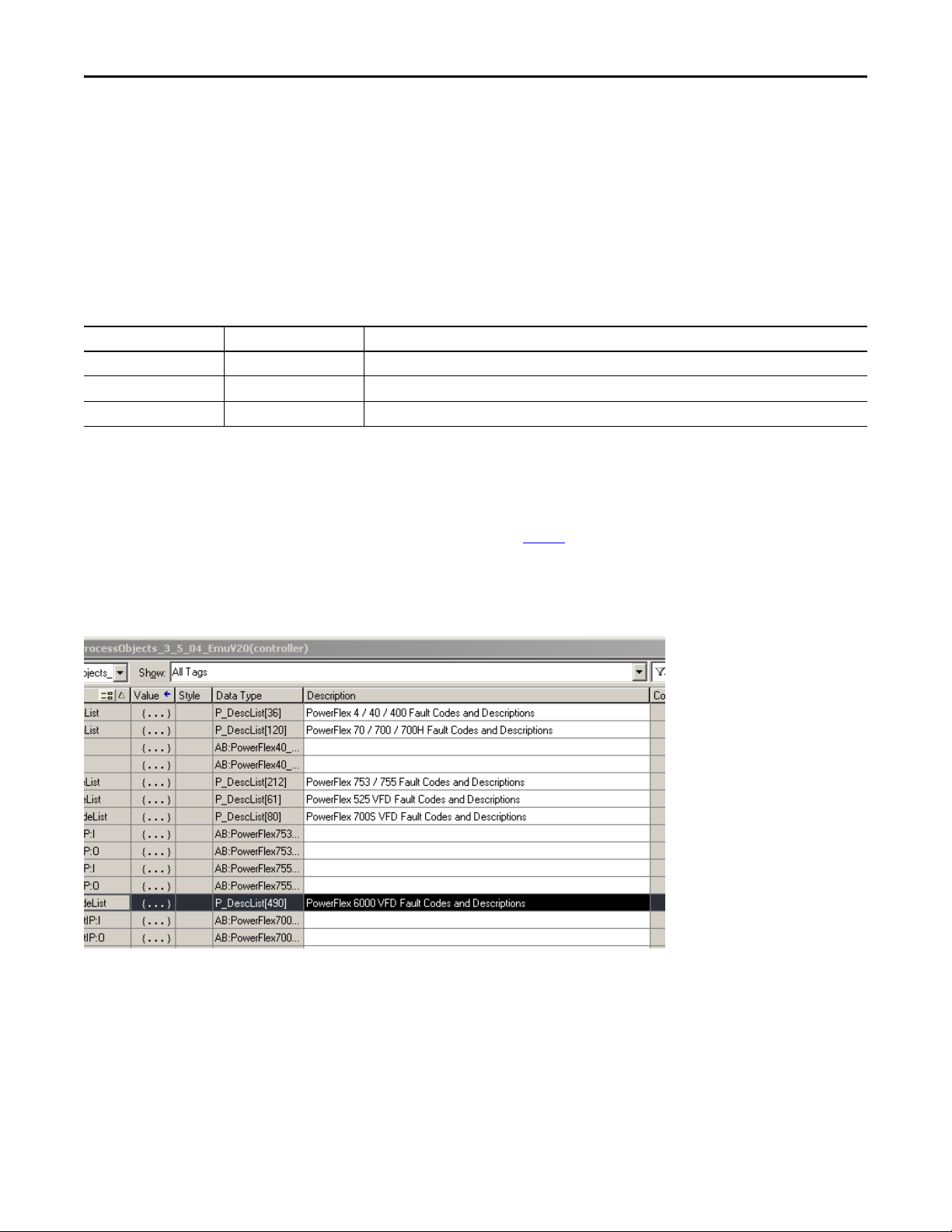
Ref_FaultCodeList P_DescList Tag containing list of fault codes (DINT) and descriptions (STRING_40).
The user-defined data types (UDTs) and the Array tag containing the list of
PowerFlex 6000 fault codes and descriptions are included in the RUNG import
that brings in the P_PF6000 Add-On Instruction. See the programming
example on page 28
for details.
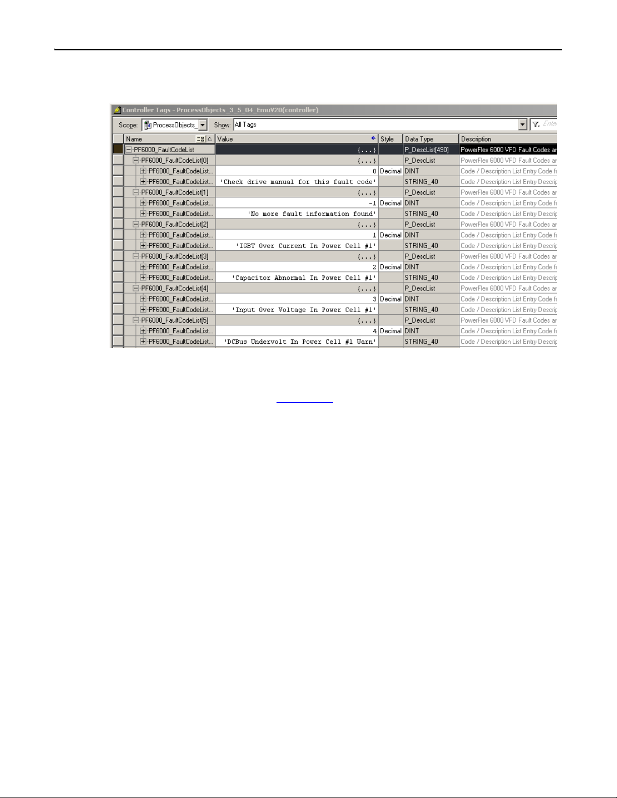
The figure shows the drive fault table tags that are in each template.
Make sure the tag 'PF6000_FaultCodeList' is entered in the P_PF6000
Ref_FaultCodeList parameter.
12 Rockwell Automation Publication SYSLIB-RM057A-EN-P - January 2017
Page 13
PowerFlex 6000 Drive (P_PF6000)
Each fault code list provides pre-configured fault codes and descriptions for a
given drive family.
For a complete list of fault codes, refer to the PowerFlex 6000 Medium Voltage
Variable Frequency Drive Firmware, Parameters, and Troubleshooting Manual,
publication 6000-TD004
.
Rockwell Automation Publication SYSLIB-RM057A-EN-P - January 2017 13
Page 14

PowerFlex 6000 Drive (P_PF6000)
Table 7 - P_PF6000 Drive Input Parameters
PowerFlex 6000 Drive Input Structure
Input parameters include the following:
• Input data elements (Inp_) are typically used to connect field inputs from
I/O modules or signals from other objects.
• Configuration data elements (Cfg_) are used to set configurable
capabilities and features of the instruction.
• Command data elements (PCmd_, OCmd_, MCmd_) are used by
program logic, operators, and maintenance personnel to request
instruction actions.
• Setting data elements (PSet_, OSet_, MSet_) are used by program logic,
operators, and maintenance personnel to establish runtime setpoints,
thresholds, and so forth. Set_ data elements (without a leading P, O, or M)
establish runtime settings regardless of role or mode.
Input Parameter Data
Type
EnableIn BOOL 1 Ladder Diagram:
Inp_PermOK BOOL 1 1 = Permissives OK, drive can start.
Inp_NBPermOK BOOL 1 1 = Non-bypassable permissives OK, drive can start.
Inp_IntlkOK BOOL 1 1 = Interlocks OK, drive can start/run.
Inp_NBIntlkOK BOOL 1 1 = Non-bypassable interlocks OK, drive can start/run.
Inp_Sim BOOL 0 Simulation input. When set to 1, the instruction keeps outputs de-energized
Inp_Hand BOOL 0 1 = Request to acquire Hand mode.
Inp_Ovrd BOOL Mode.Inp_Ovrd 0 1 =Request to acquire Override mode.
Inp_OvrdCmd SINT 0 Override mode command:
Inp_OvrdSpeed REAL 0.0 Value to set speed reference in Override mode (SpeedRef engineering units).
Inp_Reset BOOL 0 1 = Reset drive fault conditions and latched alarms.
Cfg_AllowLocal BOOL 0 1 =Allow Local Star t/Stop without alarm.
Cfg_HasPermObj BOOL 0 1 = Tells HMI a P_Perm is connected to Inp_Perm.
Cfg_HasIntlkObj BOOL 0 1 =T ells HMI a P_Intlk is connected to Inp_Intlk.
Cfg_HasResInhObj BOOL 0 1 = Tells HMI a P_ResInh Restart Inhibit is connected.
Cfg_HasRunTimeObj BOOL 0 1 =T ells HMI a P_RunTime is connected.
Alias For Default Description
If the rung-in condition is true, the instruction’s Logic routine executes. If the
rung-in condition is false, the instruction’s EnableInFalse routine executes.
Function Block Diagram:
If true, or not connected, the instruction’s Logic routine executes. If the parameter
is exposed as a pin and wired, and the pin is false, the instruction’s EnableInFalse
routine executes.
Structured Text:
No effect. The instruction’s Logic routine executes.
(zero) and simulates a working drive. When set to 0, the instruction operates the
drive normally.
0 = Release Hand mode.
0 = Release Override mode.
0 = None
1 = Stop
2 = Start
0= Start/Stop from HMI/Program only.
14 Rockwell Automation Publication SYSLIB-RM057A-EN-P - January 2017
Page 15
Table 7 - P_PF6000 Drive Input Parameters
PowerFlex 6000 Drive (P_PF6000)
Input Parameter Data
Type
Cfg_SetTrack BOOL 1 1 = PSets track OSets in Operator, OSets track PSets in Program.
Cfg_SetTrackOvrdHand BOOL 0 1 = Program/Operator settings track Override/Hand speed reference.
Cfg_PCmdClear BOOL Mode.Cfg_PCmdClear 1 When this parameter is 1, program commands are cleared once they are acted
Cfg_ProgDefault BOOL Mode.Cfg_ProgDefault 0 This parameter defines the default mode. When this parameter is 1, the mode
Cfg_OperStopPrio BOOL 0 1 = OCmd_Stop available in any mode.
Cfg_OCmdResets BOOL 0 1 = New Operator drive command resets fault.
Cfg_OvrdPermIntlk BOOL 0 1 = Override ignores bypassable permissives/interlocks.
Cfg_ShedOnFailToStart BOOL 1 1 = Stop motor and alarm on Fail to Start.
Cfg_ShedOnIOFault BOOL 1 1 = Stop motor and alarm on I/O Fault.
Cfg_SimScaleEU BOOL 0 1 = In simulation, scale Speed Ref EU to Speed Fdbk EU.
Cfg_SimScaleRaw BOOL 0 1 = In simulation, scale Speed Ref EU to raw, then raw to Speed Fdbk EU.
Cfg_HasFailToStartAlm BOOL FailToStart.Cfg_Exists 0 These parameters determine whether the corresponding alarm exists and is
Cfg_HasFailToStopAlm FailToStop.Cfg_Exists
Cfg_HasIntlkTripAlm IntlkTrip.Cfg_Exists
Cfg_HasDriveFaultAlm DriveFault.Cfg_Exists
Cfg_HasIOFaultAlm IOFault.Cfg_Exists
Cfg_FailToStar tResetReqd BOOL FailToStart.Cfg_ResetReqd 0 These parameters determine whether a reset is required to clear the alarm status.
Cfg_FailToStopResetReqd FailToStop.Cfg_ResetReqd
Cfg_IntlkTripResetReqd IntlkTrip.Cfg_ResetReqd
Cfg_DriveFaultResetReqd DriveFault.Cfg_ResetReqd
Cfg_IOFaultResetReqd IOFault.Cfg_ResetReqd
Cfg_FailToStartAckReqd BOOL FailToStart.Cfg_AckReqd 1 These parameters determine whether an acknowledgement is required for an
Cfg_FailToStopAckReqd FailToStop.Cfg_AckReqd
Cfg_IntlkTripAckReqd IntlkTrip.Cfg_AckReqd
Cfg_DriveFaultAckReqd DriveFault.Cfg_AckReqd
Cfg_IOFaultAckReqd IOFault.Cfg_AckReqd
Alias For Default Description
0 = No tracking.
upon. When set to 0, program commands remain set until cleared by the
application program logic.
IMPORTANT: Clearing this parameter online can cause unintended program
command execution.
defaults to Program if no mode is being requested. When this parameter is 0, the
mode defaults to Operator if no mode is being requested.
IMPORTANT: Changing this parameter online can cause unintended mode
changes.
0 = OCmd_Stop only in Operator and Maintenance modes.
0 = Reset required to clear fault.
0 = Always use permissives/interlocks.
0 = Alarm only on Fail to Start.
IMPORTANT: If a condition is configured to shed the device to the Off state on a
fault, a reset is required to clear the shed fault to command the drive to a state
other than Off.
0 = Alarm only on I/O Fault.
IMPORTANT: If a condition is configured to shed the device to the Off state on a
fault, a reset is required to clear the shed fault to command the drive to a state
other than Off.
checked or if the alarm does not exist and is not used. When these parameter are
1, the corresponding alarm exists.
When these parameters are 1, the alarm is latched ON when the alarm occurs.
After the alarm condition returns to normal, a reset is required to clear the alarm
status (for example, PCmd_Reset, OCmd_Reset, or Inp_Reset are required to
clear Alm_FailtoStart after the alarm is set and the value returns to normal).
When these parameter are 0, no reset is required and the alarm status is cleared
when the alarm condition returns to normal.
IMPORTANT: If the reset clears the alarm, it also acknowledges the alarm.
alarm. When these parameters are 1, the acknowledge (ack) bit is cleared when
the alarm occurs. An acknowledge command (for example,
PCmd_FailtoStartAck) are required to acknowledge the alarm. When set to 0, the
Acknowledge bit is set when an alarm occurs indicating an acknowledged alarm
and no acknowledge command is required.
Rockwell Automation Publication SYSLIB-RM057A-EN-P - January 2017 15
Page 16

PowerFlex 6000 Drive (P_PF6000)
Table 7 - P_PF6000 Drive Input Parameters
Input Parameter Data
Cfg_FailToStar tSeverity INT FailToStart.Cfg_Severity 1000 These parameters determine the severity of each alarm that gauges the color and
Cfg_FailToStopSeverity FailToStop.Cfg_Severity 1000
Cfg_IntlkTripSeverity IntlkTrip.Cfg_Severity 500
Cfg_DriveFaultSeverity DriveFault.Cfg_Severity 1000
Cfg_IOFaultSeverity IOFault.Cfg_Severity 1000
Cfg_MinSpdRef REAL 0.0 Minimum speed reference in engineering units (for limiting).
Cfg_MaxSpdRef REAL 60.0 Maximum speed reference in engineering units (for limiting).
Cfg_SpeedRefEUMin REAL 0.0 Speed reference minimum in Engineering units (for scaling).
Cfg_SpeedRefEUMax REAL 60.0 Speed reference maximum in engineering units (for scaling).
Cfg_SpeedFdbkEUMin REAL 0.0 Speed feedback minimum in engineering units (for scaling).
Cfg_SpeedFdbkEUMax REAL 60.0 Speed feedback maximum in engineering units (for scaling).
Cfg_SimRampT DINT 10 Time to ramp speed feedback when in simulation (seconds).
Cfg_FailToStar tT DINT 15 Time after start to get run feedback before fault (seconds).
Cfg_FailToStopT DINT 15 Time after stop to drop run feedback before fault (seconds).
Cfg_ResetPulseT DINT 2 Time to pulse Out_Reset to clear drive fault.
Cfg_WatchdogT DINT 5 Communication Watchdog Timeout time (sec).
Cfg_OperKeep SINT 2#0000_0000 Operator keeps control in Program mode:
Cfg_ProgKeep SINT 2#0000_0000 Program keeps control in Operator mode:
PSet_SpeedRef REAL 0.0 Program setting of speed reference (engineering units).
PSet_Owner DINT 0 Program Owner Request ID (nonzero) or Release (zero).
OSet_SpeedRef REAL 0.0 Operator setting of speed reference (engineering units).
PCmd_Start
PCmd_Stop
PCmd_Fwd
PCmd_Acq BOOL Mode.PCmd_Acq 0 When Cfg_PCmdClear is 1:
PCmd_Rel Mode.PCmd_Rel
Type
BOOL 0 When Cfg_PCmdClear is 1:
Alias For Default Description
symbol that are used to indicate alarm status on the faceplate and global object.
The following are valid values:
1…250 = Low
251…500 = Medium
501…750 = High
751…1000 = Urgent
IMPORTANT: These severity priorities drive only the indication on the global
object and faceplate. The Alarm and Events definition severity drives the color
and symbol that is used on the alarm banner. The definition severity also provides
an alarm summary and the value returned by the FactoryTalk Alarm and Events
software display commands.
Bit .0 = Reference
Bit .1 = Start/stop
Bit .0 = Reference
Bit .1 = Start/stop
• Set PCmd_Start to 1 to start the Drive
• Set PCmd_Stop to 1 to stop the motor
• These parameters are reset automatically
When Cfg_PCmdClear is 0:
• Set PCmd_Start to 1 to start the drive
• Set PCmd_Start to 0 to stop the driver
• PCmd_Stop is not used
• These parameters do not reset automatically
• Set PCmd_Acq to 1 to Acquire
• Set PCmd_Rel to 1 to Re lease
• These parameters reset automatically
When Cfg_PCmdClear is 0:
• Set PCmd_Acq to 1 to Acquire
• Set PCmd_Acq to 0 to Release
• PCmd_Rel is not used
• These parameters do not reset automatically
16 Rockwell Automation Publication SYSLIB-RM057A-EN-P - January 2017
Page 17

Table 7 - P_PF6000 Drive Input Parameters
PowerFlex 6000 Drive (P_PF6000)
Input Parameter Data
Type
PCmd_Lock BOOL Mode.PCmd_Lock 0 When Cfg_PCmdClear is 1:
PCmd_Unlock Mode.PCmd_Unlock
PCmd_Reset BOOL 0 • Set PCmd_Reset to 1 to reset all alarms requiring reset
PCmd_FailToStar tAck BOOL FailToStart.PCmd_Ack 0 • Set PCmd_<Alarm>Ack to 1 to Acknowledge alarm
PCmd_FailToStopAck FailToStop.PCmd_Ack
PCmd_IntlkTripAck IntlkTrip.PCmd_Ack
PCmd_DriveFaultAck DriveFault.PCmd_Ack
PCmd_IOFaultAck IOFault.PCmd_Ack
PCmd_FailToStar tSuppress BOOL FailToStart.PCmd_Suppress 0 When Cfg_PCmdClear is 1:
PCmd_FailToStopSuppress FailToStop.PCmd_Suppress
PCmd_IntlkTripSuppress IntlkTrip.PCmd_Suppress
PCmd_DriveFaultSuppress DriveFault.PCmd_Suppress
PCmd_IOFaultSuppress IOFault.PCmd_Suppress
PCmd_FailToStar tUnsuppress BOOL FailToStart.PCmd_Unsuppress 0
PCmd_FailToStopUnsuppress FailToStop.PCmd_Unsuppress
PCmd_IntlkTripUnsuppress IntlkTrip.PCmd_Unsuppress
PCmd_DriveFaultUnsuppress DriveFault.PCmd_Unsuppress
PCmd_IOFaultUnsuppress IOFault.PCmd_Unsuppress
PCmd_FailToStartUnshelve BOOL FailToStart.PCmd_Unshelve 0 • Set PCmd_<Alarm>Unshelve to 1 to Unshelve alarm
PCmd_FailToStopUnshelve FailToStop.PCmd_Unshelve
PCmd_IntlkTripUnshelve IntlkTrip.PCmd_Unshelve
PCmd_DriveFaultUnshelve DriveFault.PCmd_Unshelve
PCmd_IOFaultUnshelve IOFault.PCmd_Unshelve
OCmd_Start BOOL 0 Operator command to start drive.
OCmd_Stop BOOL 0 Operator command to stop drive.
OCmd_Bypass BOOL 0 Operator command to bypass all bypassable interlocks and permissives.
OCmd_Check BOOL 0 Operator command to check (not bypass) all interlocks and permissives.
MCmd_Disable BOOL 0 Maintenance command to disable drive.
MCmd_Enable BOOL 0 Maintenance command to enable (permit to run) drive.
MCmd_Acq BOOL Mode.MCmd_Acq 0 Ma intenance Command to Acquire Ownership (Op erator/Program/Overload to
MCmd_Rel BOOL Mode.MCmd_Rel 0 Maintenance Command to Release Ownership (Maintenance to Operator/
OCmd_AcqLock BOOL Mode.OCmd_AcqLock 0 Operator Command to Acquire (Program to Operator)/Lock Ownership.
Alias For Default Description
• Set PCmd_Lock to 1 to Lock
• Set PCmd_Unlock to 1 to Unlock
• These parameters are reset automatically
• When Cfg_PCmdClear is 0:
• Set PCmd_Lock to 1 to Lock
• Set PCmd_Lock to 0 to Unlock
• PCmd_Unlock is not used
• These parameters do not reset automatically
• This parameter is always reset automatically
• These parameters are reset automatically
• Set PCmd_<Alarm>Suppress to 1 to sup press alarm
• Set PCmd_<Alarm>Unsuppress to 1 to unsuppress alarm
• These parameters reset automatically
When Cfg_PCmdClear is 0:
• Set PCmd_<Alarm>Suppress to 1 to sup press alarm
• Set PCmd_<Alarm>Suppress to 0 to unsuppress alarm
• PCmd_<Alarm>Unsuppress is not used
• These Parameters do not reset automatically
• These parameters are reset automatically
Maintenance).
Program/Overload).
Rockwell Automation Publication SYSLIB-RM057A-EN-P - January 2017 17
Page 18

PowerFlex 6000 Drive (P_PF6000)
Table 7 - P_PF6000 Drive Input Parameters
Input Parameter Data
Type
OCmd_Unlock BOOL Mode.OCmd_UnlockRel 0 Operator Command to Unlock/Release (Operator to Program) Ownership
OCmd_Reset BOOL 0 Operator command to reset all alarms requiring reset.
OCmd_ResetAckAll BOOL 0 Operator command to acknowledge and reset all alarms and latched shed
Alias For Default Description
conditions.
18 Rockwell Automation Publication SYSLIB-RM057A-EN-P - January 2017
Page 19

Table 8 - P_PF6000 Drive Output Parameters
PowerFlex 6000 Drive (P_PF6000)
PowerFlex 6000 Drive Output Structure
Output parameters include the following:
• Value data elements (Val_) are numeric outputs of the instruction for
use by the HMI. Values can also be used by other application logic or
software packages.
• Source and Quality data elements (SrcQ_) are outputs of the instruction
used by the HMI to indicate PV source and quality.
• Status data elements (Sts_) are bit outputs of the instruction for use by the
HMI. Status bits can also be used by other application logic.
• Error data elements (Err_) are outputs of the instruction that indicate a
particular configuration error. If any Err_ bit is set then the Sts_Err
configuration error summary status is set and the Invalid Configuration
indicator is displayed on the HMI.
• Not Ready data elements (Nrdy_) are bit outputs of the instruction for use
by the HMI for displaying the Device Not Ready indicator. Status bits can
also be used by other application logic.
• Alarm data elements (Alm_) are outputs of the instruction that indicate a
particular alarm has occurred.
• Acknowledge data elements (Ack_) are outputs of the instruction that
indicate the corresponding alarm has been acknowledged.
• Ready data elements (Rdy_) are bit outputs of the instruction used
by the HMI to enable or disable Command buttons and Setting
entry fields.
Output Parameter Data Type Alias For Description
EnableOut BOOL Enable output: The EnableOut signal is not manipulated by this instruction. Its output state
Val_SpeedRef REAL Speed reference (target, in engineering units) to drive.
Val_SpeedFdbk REAL Speed feedback (actual, in engineering units) from drive.
Val_SpeedRefRaw REAL Copy of speed reference output (in raw units) for faceplate.
Val_SpeedFdbkRaw REAL Copy of speed feedback input (in raw units) for faceplate.
Val_SpeedRefEUMin REAL Minimum of speed reference = MIN (Cfg_SpeedFdbkEUMin, Cfg_SpeedFdbkEUMax).
Val_SpeedRefEUMax REAL Maximum of speed re ference = MAX (C fg_SpeedFdbkEUMin, Cfg_SpeedFdbkEUMax).
Val_SpeedFdbkEUMin REAL Minimum of speed feedback = MIN (Cfg_SpeedFdbkEUMin, Cfg_SpeedFdbkEUMax).
Val_SpeedFdbkEUMax REAL Maximum of speed feedback = MAX (Cfg_SpeedFdbkEUMin, Cfg_SpeedFdbkEUMax).
Val_MotorCurrent REAL Drive output current (amps).
Val_MotorCurrentPct REAL Motor current (% full load amps).
Val_MotorVoltage REAL Motor voltage (volts).
Val_Outpu tPower REAL Drive output power (k W).
Val_MotorPowerPct REAL Motor power (% rated power).
always reflects EnableIn input state.
Rockwell Automation Publication SYSLIB-RM057A-EN-P - January 2017 19
Page 20

PowerFlex 6000 Drive (P_PF6000)
Table 8 - P_PF6000 Drive Output Parameters
Output Parameter Data Type Alias For Description
SrcQ_IO SINT I/O signal source and quality.
SrcQ Final drive source and quality.
GOOD 0 = I/O live and confirmed good quality
1 = I/O live and assumed good quality
2 = No feedback configured, assumed good quality
TEST 8 = Device simulated
9 = Device loopback simulation
10 = Manually entered value
UNCERTAIN 16 = Live input, off-specification
17 = Value substituted at device/bus
18 = Value substituted by maintenance (Has and not Use)
19 = Shed, using last good value
20 = Shed, using replacement value
BAD 32 = Signal failure (out-of-range, NaN, invalid combination)
33 = I/O channel fault
34 = I/O module fault
35 = Bad I/O configuration (for example, scaling parameters)
Val_Cmd SINT Device command:
Val_Fdbk SINT Device feedback:
Val_Sts SINT Device confirmed status:
Val_Fault SINT Device fault status:
Val_Mode SINT Mode.Val The current mode is shown with status bits and also as an enumeration ‘Val_Mode’ as follows:
Val_Owner DINT Current object owner ID (0 = not owned).
0 = None
1 = Stop
2 = Start
0 = Stopped
1 = Running
0 = None
1 = Stopped
2 = Running
6 = Stopping
7 = Starting
33 = Disabled
0 = None
16 = Fail to Start
17 = Fail to Stop
18 = Drive Fault
32 = I/O Fault
34 = Configuration error
0 = No mode
1 = Hand
2 = Maintenance
3 = Override
4 = Program (locked)
5 = Operator (locked)
6 = Program (unlocked, Operator is default)
7 = Operator (unlocked, Program is default)
8 = Program (unlocked, Program is default)
9 = Operator (unlocked, Operator is default)
20 Rockwell Automation Publication SYSLIB-RM057A-EN-P - January 2017
Page 21

PowerFlex 6000 Drive (P_PF6000)
Table 8 - P_PF6000 Drive Output Parameters
Output Parameter Data Type Alias For Description
Val_Notify SINT Current alarm level and acknowledgement (enumeration):
0 = No alarm
1 = Alarm cleared: a reset or acknowledge is required
2 = Low (acknowledged)
3 = Low (unacknowledged)
4 = Medium (acknowledged)
5 = Medium (unacknowledged)
6 = High (acknowledged)
7 = High (unacknowledged)
8 = Urgent (acknowledged)
9 = Urgent (unacknowledged)
Sts_Stopped BOOL 1 = Drive requested to stop and is confirmed stopped.
Sts_Starting BOOL 1 = Drive requested to run and awaiting run feedback.
Sts_Running BOOL 1 = Drive requested to run and is confirmed running.
Sts_Stopping BOOL 1 = Drive requested to stop and awaiting stopped feedback.
Sts_NotReady BOOL 1 = Drive is not ready to run.
Sts_WatchdogTO BOOL 1 = Drive communication watchdog timed out (communication fail).
Sts_SpeedLimited BOOL 1 = Speed reference setting exceeds configured maximum/minimum limit.
Sts_LogicSts INT Logic status word from drive input assembly (see drive manual for bit assignments).
Sts_Available BOOL 1 = Drive available for control by automation (program).
Sts_Bypass BOOL 1 = Bypassable interlocks and permissives are bypassed.
Sts_BypActive BOOL 1 = Bypassing active (bypassed or maintenance).
Sts_Disabled BOOL 1 = Drive is disabled.
Sts_NotRdy BOOL 1 = Motor is not ready to run (independent of mode). - Check interlocks and permissives.
Nrdy_Disabled BOOL 1 = Device not ready due to the following:
Nrdy_CfgErr
Nrdy_Intlk
Nrdy_Perm
Nrdy_OperPrio
Nrdy_Fail
Nrdy_IOFault
Nrdy_Trip
Nrdy_DriveNR
Nrdy_NoMode
Sts_MaintByp BOOL 1 = Maintenance bypass is active, display icon.
Sts_AlmInh BOOL 1 = Alarm is shelved, disabled, or suppressed, display icon.
Sts_Err BOOL 1 = Error in configuration: See detail bits for reason.
Err_Timer BOOL 1 = Error in configuration: Invalid check or reset pulse time (use 0…2,147,483).
Err_Sim BOOL 1 = Error in configuration: Simulation timer preset (use 0…2,147,483).
Err_Alarm BOOL 1 = Error in configuration: Alarm minimum On time or severity.
Err_FdbkEU BOOL 1 = Error in configuration: Speed Fdbk EU Min = Max.
Err_RefLim BOOL 1 = Error in configuration: Speed Ref Limit Min > Max.
• Device disabled by Maintenance
• Configuration error
• Interlock not OK
• Permissive not OK
• Operator state 0 priority command requires reset
• Device failure (shed requires reset),
• I/O Fault (shed requires reset)
• Device tripped (Drive fault)
• Drive not ready
• Device logic disabled/no mode.
Rockwell Automation Publication SYSLIB-RM057A-EN-P - January 2017 21
Page 22

PowerFlex 6000 Drive (P_PF6000)
Table 8 - P_PF6000 Drive Output Parameters
Output Parameter Data Type Alias For Description
Err_RefEU BOOL 1 = Error in configuration: Speed Ref EU Min = Max.
Sts_Hand BOOL Mode.Sts_Hand 1 = Mode is Hand (supersedes Maintenance, Override, Program, Operator).
Sts_Maint BOOL Mode.Sts_Maint 1 = Mode is Maintenance (supersedes Override, Program, Operator).
Sts_Ovrd BOOL Mode.Sts_Ovrd 1 = Mode is Override (supersedes Program, Operator).
Sts_Prog BOOL Mode.Sts_Prog 1 = Mode is Program (auto).
Sts_Oper BOOL Mode.Sts_Oper 1 = Mode is Operator (manual).
Sts_ProgOperLock BOOL Mode.Sts_ProgOperLock 1 = Program or Operator has requested mode lock.
Sts_NoMode BOOL Mode.Sts_NoMode 1 = No mode (disabled because EnableIn is false).
Sts_MAcqRcvd BOOL Mode.Sts_MAcqRcvd 1=Maintenance Acquire command received this scan
Sts_FailToStar t BOOL FailToStart.Inp 1 = Drive failed to start.
Sts_FailToStop FailToStop.Inp 1 = Drive failed to stop.
Sts_IntlkTrip IntlkTrip.Inp 1 = Drive was stopped by an interlock not OK (one-shot).
Sts_DriveFault DriveFault.Inp 1 = Drive Fault (see drive display or manual).
Sts_IOFault IOFault.Inp I/O Communication fault status:
0 = OK
1 = Bad
Ack_FailToStart BOOL FailToStart.Ack 1 = Fail to Start, Fail to Stop, Interlock Trip, Drive Fault, or I/O Fault alarm has been
Ack_FailToStop FailToStop.Ack
Ack_IntlkTrip IntlkTrip.Ack
Ack_DriveFault DriveFault.Ack
Ack_IOFault IOFault.Ack
Alm_FailToStart BOOL FailToStart.Alm 1 = Drive failed to start alarm.
Alm_FailToStop FailToStop.Alm 1 = Drive failed to stop alarm.
Alm_IntlkTrip IntlkTrip.Alm 1 = Alarm: Drive stopped by an interlock not OK.
Alm_Drive Fault Dr iveFa ult.A lm 1 = Al arm: Driv e Faul t (se e dri ve di spla y or m anual) .
Alm_IOFault IOFault.Alm 1 = I/O Fault alarm.
Sts_FailToStartDisabled BOOL FailToStart.Disabled 1 = Fail to Start, Fail to Stop, Interlock Trip, Drive Fault, or I/O Fault alarm has been disabled (by
Sts_FailToStopDisabled FailToStop.Disabled
Sts_IntlkTripDisabled IntlkTrip.Disabled
Sts_DriveFaultDisabled DriveFault.Disabled
Sts_IOFaultDisabled IOFault.Disabled
Sts_FailToStartSuppressed BOOL FailToStart.Suppressed 1 = Fail to Start, Fail to Stop, Interlock Trip, Drive Fault, or I/O Fault alarm has been suppressed
Sts_FailToStopSuppressed FailToStop.Suppressed
Sts_IntlkTripSuppressed IntlkTrip.Suppressed
Sts_DriveFaultSuppressed DriveFault.Suppressed
Sts_IOFaultSuppressed IOFault.Suppressed
acknowledged.
Maintenance).
by Program.
22 Rockwell Automation Publication SYSLIB-RM057A-EN-P - January 2017
Page 23

PowerFlex 6000 Drive (P_PF6000)
Table 8 - P_PF6000 Drive Output Parameters
Output Parameter Data Type Alias For Description
Sts_FailToStartShelved BOOL FailToStart.Shelved 1 = Fail to Start, Fail to Stop, Interlock Trip, Drive Fault, or I/O Fault alarm has been shelved (by
Sts_FailToStopShelved FailToStop.Shelved
Sts_IntlkTripShelved IntlkTrip.Shelved
Sts_Dr iveFaultShelved DriveFaul t.Shelved
Sts _IO Faul tSh elv ed IO Faul t.S hel ved
Rdy_Start BOOL 1 = Ready to receive OCmd for Start, Stop, Bypass, or Check (enables HMI button).
Rdy_Stop
Rdy_Bypass
Rdy_Check
Rdy_Disable BOOL 1 = Ready to receive MCmd Disable or Enable (enables HMI button).
Rdy_Enable
Rdy_Reset BOOL 1 = Ready to receive OCmd_Reset (enables HMI button).
Rdy_ResetAckAll BOOL 1 = At least one alarm or latched shed condition requires reset or acknowledgement.
Rdy_SpeedRef BOOL 1 = Ready to receive OSet_SpeedRef (enables data entry field).
P_PF6000 BOOL Unique parameter name for auto-discovery.
Operator).
PowerFlex 6000 Drive Local Configuration Tags
Configuration parameters that are arrayed, string, or structure data types cannot
be configured as parameters for Add-On Instructions. Configuration parameters
of these types appear as local tags to the Add-On Instruction. Local tags can be
configured through the HMI faceplates or in Studio 5000 Logix Designer
application by opening the Instruction Logic of the Add-On Instruction instance
and then opening the Data Monitor on a local tag. These parameters cannot be
modified by using controller logic or Logix Designer application export/import
functionality.
Table 9 - Local Configuration Tags
Tag Name Data Type Default Description
Cfg_Desc STRING_40 'PowerFlex 6000
Varia ble Fr eque ncy
Drive'
Cfg_Label STRING_20 'Motor Speed Control' Label for graphic symbol displayed on HMI. This string appears on the graphic symbol.
Cfg_SpeedFdbkEU STRING_8 'Hz' Speed feedback engineering units for display on HMI.
Cfg_SpeedRefEU STRING_8 Speed reference engineering units for display on HMI.
Cfg_Tag STRING_20 'P_PF6000' Tagname for display on HMI. This string is shown in the title bar of the faceplate.
Val_ Fault Code D INT[10] {…} Fa ult co de nu mbers fo r active faults in drive (-1 = no fault).
Val_FaultCode[0] DINT 0
Val_ Faul tCod e[1 ]
Val_ Faul tCod e[2 ]
Val_ Faul tCod e[3 ]
Description for display on HMI. This string is shown in the title bar of the faceplate.
Rockwell Automation Publication SYSLIB-RM057A-EN-P - January 2017 23
Page 24

PowerFlex 6000 Drive (P_PF6000)
Table 9 - Local Configuration Tags
Val_FaultCode[4] DINT 0 Fault code numbers for active faults in the drive (-1 = no fault).
Val_ Faul tCod e[5 ]
Val_ Faul tCod e[6 ]
Val_ Faul tCod e[7 ]
Val_ Faul tCod e[8 ]
Val_ Faul tCod e[9 ]
Val_FaultDesc STRING_40[10] {…} Description of the drive fault (given Fault Code).
Val_FaultDesc[0] STRING_40
Val_ Faul tDe sc[1 ]
Val_ Faul tDe sc[2 ]
Val_ Faul tDe sc[3 ]
Val_ Faul tDe sc[4 ]
Val_ Faul tDe sc[5 ]
Val_ Faul tDe sc[6 ]
Val_ Faul tDe sc[7 ]
Val_ Faul tDe sc[8 ]
Val_ Faul tDe sc[9 ]
24 Rockwell Automation Publication SYSLIB-RM057A-EN-P - January 2017
Page 25

PowerFlex 6000 Drive (P_PF6000)
IMPORTANT
Operations
This section describes the primary operations for Add-On Instructions.
Modes
This instruction uses the following standard modes, which are implemented by
using an embedded P_Mode Add-On Instruction.
Mode Description
Operator The Operator owns control of the device. Operator commands (OCmd_) and Operator settings
(OSet_) from the HMI are accepted.
Program Program logic owns control of the device. Program commands (PCmd_) and Program settings
(PSet_) are accepted.
Override Priority logic owns control of the device and supersedes Operator and Program control. Override
Inputs (Inp_OvrdCmd and other Inp_OvrdXxxx values) are accepted. If so configured,
bypassable interlocks and permissives are bypassed.
Maintenance Maintenance owns control of the device and supersedes Operator, Program, and Override
control. Operator commands and settings from the HMI are accepted. Bypassable interlocks and
permissives are bypassed, and device timeout checks are not processed.
Hand Hardwired logic or other logic outside the instruction owns control of the device. The instruction
tracks the state of the device for bumpless transfer back to one of the other modes.
No Mode The device is disabled and has no owner because the EnableIn input is false. The main
instruction Logic routine is not being scanned. See Execution sec tion for more information on
EnableInFalse processing.
Instructions with Cfg_OperKeep and Cfg_ProgKeep keep some aspects of the
device operation with the operator or program regardless of whether the main
mode is Program or Operator mode.
See Rockwell Automation Library of Process Objects: Common Mode Block
(P_Mode) Reference Manual, publication SYSLIB-RM005
, for more
information.
Rockwell Automation Publication SYSLIB-RM057A-EN-P - January 2017 25
Page 26

PowerFlex 6000 Drive (P_PF6000)
Alarms
This instruction uses the following alarms, which are implemented by using
embedded P_Alarm and P_Gate Add-On Instructions.
Alarm Name P_Alarm Name P_Gate Name Description
Drive Fault DriveFault None Raised when the drive detects a fault and sets its
Faulted status bit. Check the Fault Code and
description to determine the cause. Issuing a Reset of
this object causes a Clear Fault command to be sent to
the drive in an attempt to clear the fault.
Fail to Start FailToStart None Raised when the drive has and is using run feedback,
an attempt is made to start the drive, and the run
feedback does not indicate that the drive is running
within the configured time. If Fail to Start is
configured as a shed fault, the drive is stopped and a
reset is required to start the drive.
Fail to Stop FailToStop None Raised when the drive has and is using run feedback,
an attempt is made to stop the drive, and the run
feedback does not indicate that the drive stopped
within the configured time.
Interlock Trip IntlkTrip None Raised when the drive is running and an interlock ’not
OK’ condition causes the drive to stop.
If interlocks are not bypassed, a bypassable inter lock
or a non-bypassable interlock 'not OK' condition
initiates an interlock trip. If interlocks are bypassed,
only a non-bypassable interlock 'not OK' condition
initiates an interlock trip.
I/O Fault IOFault None Raised when the Inp_IOFault input is true. This input
is used to indicate to the instruc tion that a
communication failure has occurred for its I/O. If the
I/O Fault is configured as a shed fault, the drive is
stopped and not per mitted to start until reset.
Parameters of the P_Alarm object can be accessed by using the following
convention: [P_Alarm Name].[P_Alarm Parameter].
See Rockwell Automation Library of Process Objects: Common Alarm Block
(P_Alarm) Reference Manual, publication SYSLIB-RM002
, for more
information.
26 Rockwell Automation Publication SYSLIB-RM057A-EN-P - January 2017
Page 27
PowerFlex 6000 Drive (P_PF6000)
Simulation
Simulation in P_PF6000 de-energizes the outputs, ignores inputs, and provides
the feedback of a working drive. It lets you operate the Add-On Instruction as if a
working drive, even if no drive is physically present.
You must set the Inp_Sim parameter in the controller to ‘1’ to enable simulation.
The Simulation icon is displayed at the bottom left of the Operator
faceplate indicating the device is in simulation.
You can also use Cfg_SimRampT to set the time (in seconds) to ramp the speed
feedback.
When you have finished in simulation, set the Inp_Sim parameter in the
controller to ‘0’ to return to normal operation.
Execution
The following table explains the handling of instruction execution conditions.
Condition Description
EnableIn False (false rung) Processing for EnableIn False (false rung) is handled the
Powerup (prescan, first scan) Processing of modes and alarms on Prescan and Powerup
Postscan (SFC Transition) No SFC Postscan logic is provided.
same a s if the dri ve were Disa bled by Comm and. The drive
outputs are de-energized and the drive is shown as
disabled on the HMI.
is handled by the embedded P_Mode and P_Alarm
Add-On Instructions. See their specifications for details.
On Powerup, the drive is treated as if it had been
Commanded to Stop.
See the Logix5000™ Controllers Add-On Instructions Programming Manual,
publication 1756-PM010
, for more information.
Rockwell Automation Publication SYSLIB-RM057A-EN-P - January 2017 27
Page 28

PowerFlex 6000 Drive (P_PF6000)
Bits used by Add-On Instruction.
Bits not used by
Add-On Instruction and
available for use.
Programming Example
This example uses the P_PF6000 instruction to control the motor of a planetary
mixer in a concrete batch plant.
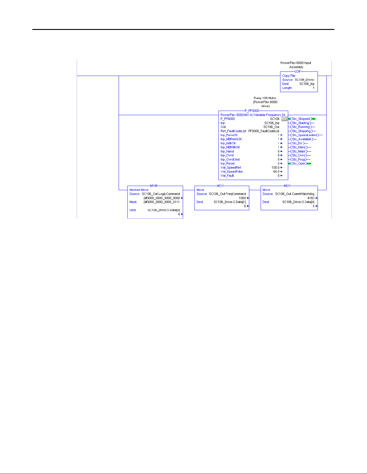
In the drive command word, the Add-On Instruction uses bits .0...3. The
instruction does not use the rest of the bits in the 'Out' reference parameter in the
InOut structure. These unused bit are available for your application to use.
Follow these steps to import the P_PF6000 rung into your project.
1. On the Controller Organizer, add your PowerFlex drive to the I/O
Configuration and name the drive.
2. Under Tasks, click in front of Main Task.
3. Double-click Main_Routine to open this ladder logic routine.
4. Right-click one of the rungs and choose Import rungs.
28 Rockwell Automation Publication SYSLIB-RM057A-EN-P - January 2017
Page 29
PowerFlex 6000 Drive (P_PF6000)
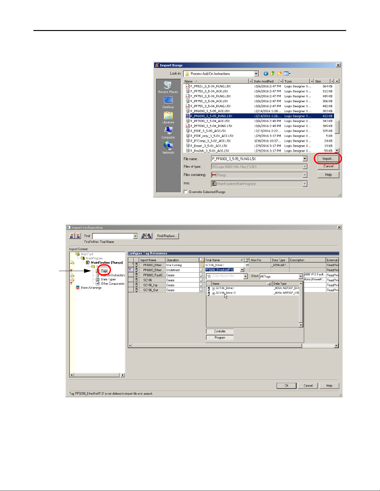
5. On the Import rungs dialog box, select the P_PF6000 instruction and
click Import.
During the import process, you can name the tags for the routine in the
Import Configuration dialog box.
6. Click Tags in the Import Content tree and type the names of the variables
that match your process and the drive name in the Final Name column.
Rockwell Automation Publication SYSLIB-RM057A-EN-P - January 2017 29
Page 30
PowerFlex 6000 Drive (P_PF6000)
Your ladder logic routine now looks like the example. Observe that the tag
names and your drive's name are automatically placed in the instruction.
30 Rockwell Automation Publication SYSLIB-RM057A-EN-P - January 2017
Page 31
PowerFlex 6000 Drive (P_PF6000)
Display Elements
The P_PF6000 instruction uses the same HMI display elements that are used for
the Variable Speed Drive (P_VSD) instruction.
A display element (global object) is created once and can be referenced multiple
times on multiple displays in an application. When changes are made to the
original (base) object, the instantiated copies (reference objects) are
automatically updated. Use of global objects, with tag structures in the
ControlLogix system, aid consistency and save engineering time.
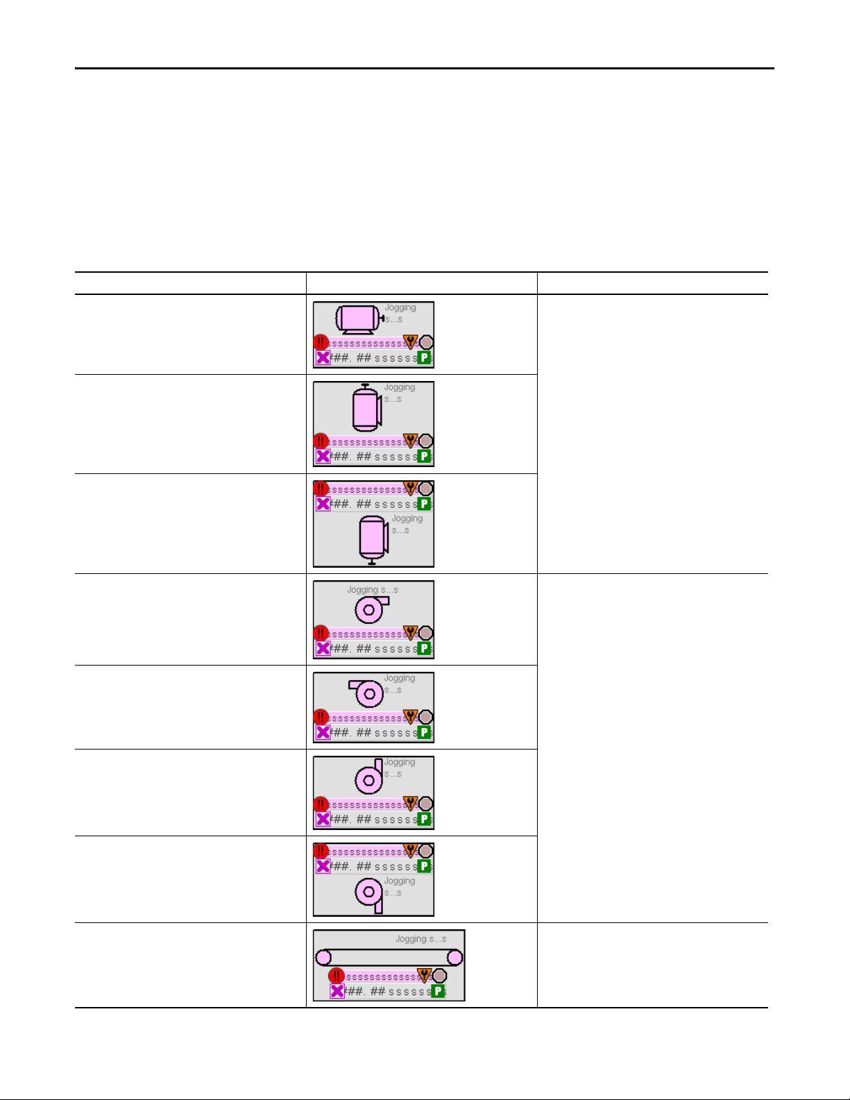
Table 10 - P_PF6000 Drive Display Elements Description
Display Element Name Display Element Description
GO_P_VSD_R These display elements show the different
GO_P_VSD_U
GO_P_VSD_D
motor positions.
GO_P_VSD_Blower_R These display elements show the different
GO_P_VSD_Blower_L
GO_P_VSD_Blower_U
GO_P_VSD_Blower_D
GO_P_VSD_Conveyer_R This display element illustrates a conveyer.
blower positions.
Rockwell Automation Publication SYSLIB-RM057A-EN-P - January 2017 31
Page 32

PowerFlex 6000 Drive (P_PF6000)
Table 10 - P_PF6000 Drive Display Elements Description
Display Element Name Display Element Description
GO_P_VSD_Inline_U These display elements show the different
GO_P_VSD_Inline_R
GO_P_VSD_Inline_L
GO_P_VSD_Inline_D
inline motor positions.
GO_P_VSD_Pump_R These display elements show the different
GO_P_VSD_Pump_L
GO_P_VSD_Pump_U
GO_P_VSD_Agitator_D This display element illustrates an agitator.
GO_P_VSD_Mixer_U This display elements shows a mixer.
pump positions.
32 Rockwell Automation Publication SYSLIB-RM057A-EN-P - January 2017
Page 33

PowerFlex 6000 Drive (P_PF6000)
Alarm Border
Status/Quality Indicator
Label
State Text
Mode Indicator
Engineering Units TextSpeed Feedback Display
Alarm Indicator
Status/Quality Indicator
Maintenance Bypass Indicator
Table 10 - P_PF6000 Drive Display Elements Description
Display Element Name Display Element Description
GO_P_VSD_RPump_U This display element shows a rotary gear pump.
GO_P_VSD_Fan_D This display element shows a fan.
Common attributes of the P_PF6000 global objects include the following:
• Graphical representation of the driven equipment
• Speed feedback display with engineering units
• Status/quality indicators
• Mode indicator
• Maintenance Bypass indicator
• State
• Label
• Color changing alarm border that blinks on unacknowledged alarm
• Alarm indicator that changes color with the severity of an alarm
Rockwell Automation Publication SYSLIB-RM057A-EN-P - January 2017 33
Page 34

PowerFlex 6000 Drive (P_PF6000)
State Indicators
The State Indicator text changes and the display element color changes
depending on the state of the drive.
Color State
Blue Stopping
Dark gray Stopped
Light blue Jogging
Blue Starting
White Runn ing
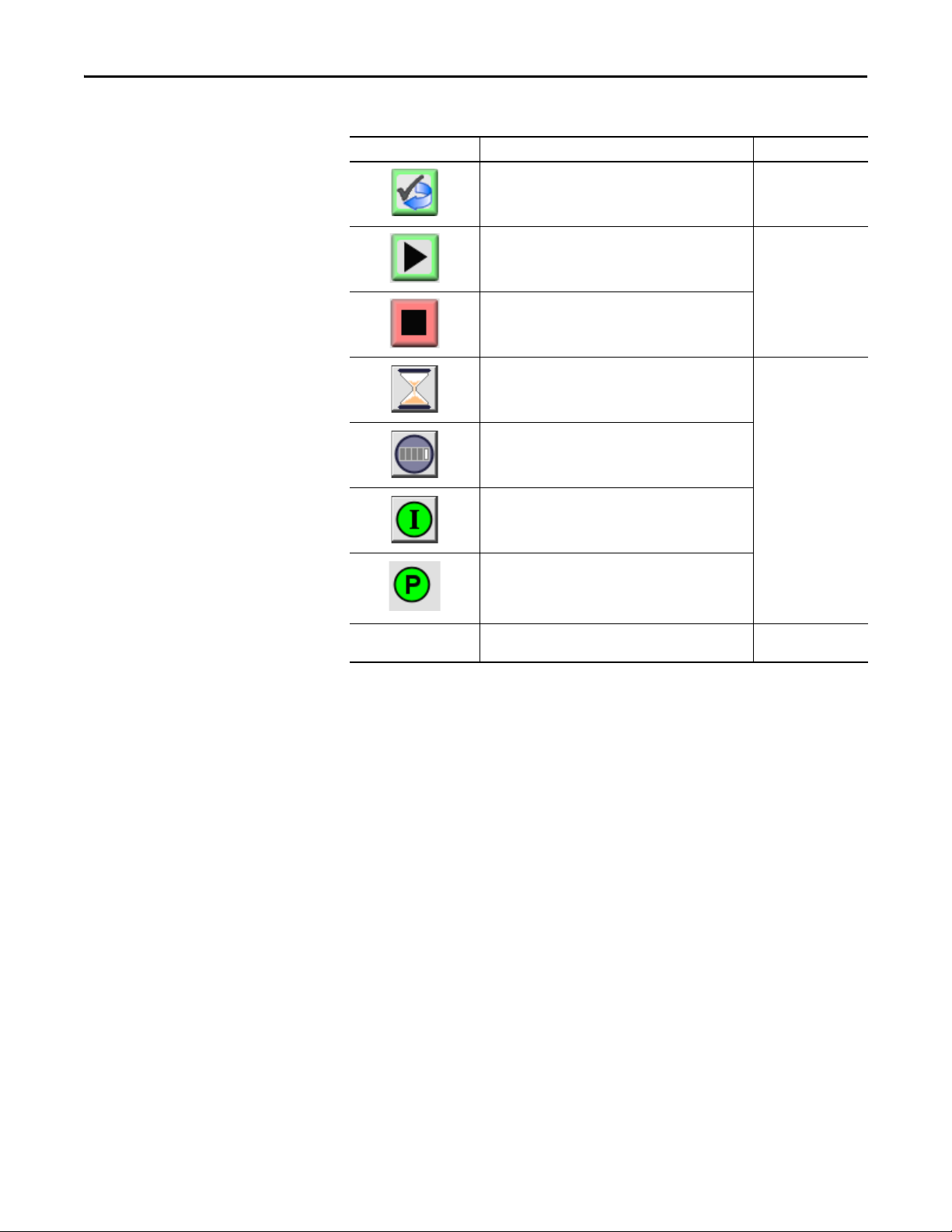
Status/Quality Indicators
One of these symbols appears on the graphic symbol when the described
condition is true.
Graphic Symbol Description
Invalid configuration.
Data quality bad/failure.
Data Quality degraded: uncertain, test, simulation, substitution, or out of specification.
The input or device has been disabled.
Device not ready to operate.
Speed reference limited to minimum/maximum.
Motor is at target speed.
Drive is accelerating.
Drive is decelerating.
34 Rockwell Automation Publication SYSLIB-RM057A-EN-P - January 2017
Page 35

PowerFlex 6000 Drive (P_PF6000)
TIP
TIP
When the Invalid Configuration indicator appears, you can find what
configuration setting is invalid by following the indicators. Click the graphic
symbol to open the faceplate. The Invalid Configuration indicator appears next
to the appropriate tab at the top of the faceplate to guide you in finding the
configuration error. Once you navigate to the tab, the misconfigured item is
flagged with this indicator or appears in a magenta box.
For the PowerFlex 6000 Drive Instruction, the Invalid Configuration Indicator
appears under the following conditions:
• The Fail to Start check time, Fail to Stop check time, Reset Pulse time,
or Maximum Jog time is set to a value less than zero or greater than
2,147,483 seconds.
• The Speed Scaled EU Minimum and EU Maximum scaling parameters are
set to the same value.
• The Maximum Speed Reference clamp value is less than the Minimum
Speed Reference clamp value, or either clamp value is less than zero.
• The Simulated Speed Ramp Time is set to a value less than zero or greater
than 2,147,483 seconds.
• An Alarm Minimum On Time is set to a value less than zero or greater
than 2,147,483 seconds.
• Alarm Severity is set to a value less than 1 or greater than 1000.
When the Not Ready indicator appears, you can find what condition is
preventing operation by following the indicators. Click the graphic symbol to
open the faceplate. The Not Ready indicator appears next to the appropriate
tab at the top of the faceplate to guide you in finding the condition. When you
navigate to the tab, the condition preventing operation is flagged.
For the PowerFlex 6000 Drive Instruction, the Device Not Ready indicator
appears under the following conditions:
• Device has been disabled by Maintenance.
• There is a configuration error.
• An Interlock or Permissive is not OK.
• Operator state 0 priority command requires reset.
• There has been a device failure or I/O Fault and Shed requires reset.
• Device has tripped and generated a Drive Fault.
• Drive is not ready.
• Device logic is disabled or there is no mode.
Rockwell Automation Publication SYSLIB-RM057A-EN-P - January 2017 35
Page 36

PowerFlex 6000 Drive (P_PF6000)
TIP
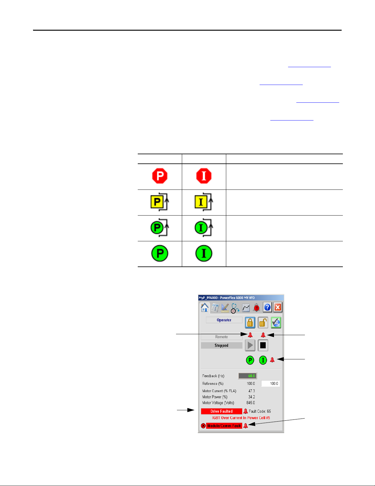
Mode Indicators
One of these symbols appears on the right side of the graphic symbol to indicate
the mode of the object instruction.
Graphic Symbol Description
Transparent Operator mode (if the default mode is Operator and the current mode is Operator, the mode
indicator is transparent).
Operator mode (if the default mode is Program).
Operator mode locked.
Transparent Program mode (if the default mode is Program and the current mode is Program, the mode
indicator is transparent).
Program mode (if the default mode is Operator).
Program mode locked.
Override mode
Maintenance mode.
Hand mode
No mode.
The images provided for the Operator and Program default modes are
transparent; therefore, no mode indicators are visible if the device is in its
default mode. This behavior can be changed by replacing the image files for
these mode indicators with images that are not transparent.
See Rockwell Automation Library of Process Objects: Common Mode Block
(P_Mode) Reference Manual, publication SYSLIB-RM005
information.
36 Rockwell Automation Publication SYSLIB-RM057A-EN-P - January 2017
, for more
Page 37

PowerFlex 6000 Drive (P_PF6000)
TIP
Alarm Indicators
One of these symbols appears on the left side of the label to indicate the described
alarm condition. The alarm border and label background blink if
acknowledgement of an alarm condition is required. Once the alarm is
acknowledged, the alarm border and label background remain the color that
corresponds to the severity of the alarm.
Symbol Border and Label Background Description
No change in color Alarm Inhibit: an alarm is suppressed by the Program,
disabled by Maintenance, or shelved by the Operator.
White Return to normal (no alarm condition), but a previous
Blue Low severity alarm.
Yel low Me diu m se ver ity ala rm.
Red High severity alarm.
Magenta Urgent severity alarm.
No symbol No change in color No alarm or alarm inhibit condition, and all alarms
alarm has not been acknowledged.
are acknowledged.
See Rockwell Automation Library of Process Objects: Common Alarm Block
(P_Alarm) Reference Manual, publication SYSLIB-RM002
, for more
information.
Maintenance Bypass Indicator
This symbol appears to the right of the label to indicate that a maintenance
bypass has been activated.
Graphic Symbol Description
A maintenance bypass is active.
No symbol displayed No maintenance bypass is active.
When the Maintenance Bypass Indicator appears, you can find what condition
was bypassed by following the indicators. Click the graphic symbol to open the
faceplate. The Maintenance Bypass Indicator appears next to the appropriate
tab at the top of the faceplate to guide you in finding the bypass. Once you
navigate to the tab, the bypassed item is flagged with this indicator.
For the PowerFlex 6000 Drive Instruction, the Maintenance Bypass Indicator
appears when the bypassable interlocks and permissives have been bypassed.
Rockwell Automation Publication SYSLIB-RM057A-EN-P - January 2017 37
Page 38

PowerFlex 6000 Drive (P_PF6000)
TIP
Using Display Elements
The global objects for P_PF6000 can be found in the global object file
(RA-BAS) P_VSD Graphics Library.ggfx. Follow these steps to use a
global object.
1. Copy the global object from the global object file and paste it in the
display file.
2. In the display, right-click the global object and choose Global Object
Parameter Values.
The Global Object Parameter Values dialog box appears.
3. Type the tag or value in the Value column as specified in the Description
column.
You can click the ellipsis (. . .) to browse and select a tag.
Values for items marked ‘(optional)’ can be left blank.
38 Rockwell Automation Publication SYSLIB-RM057A-EN-P - January 2017
Page 39

PowerFlex 6000 Drive (P_PF6000)
Click to navigate to full faceplate.
4. Click OK.
The global object parameters are as follows.
Parameter Required Description
#102 Y Object tag to point to the name of the associated object Add-On Instruction
#103 Y Path used for display navigation features to other objects. Include program
#120 N Additional parameter to pass to the display command to open the faceplate.
#121 N Additional parameter to pass to the display command to open the faceplate.
#122 Y These are the options for the global objec t display:
in the controller.
scope if tag is a program scope tag.
Typ ica lly us ed t o de fin e position for the faceplate.
if defining X and Y coordinate, separate parameters so that X is defined by
#120 and Y is defined by #121. This lets the same parameters be used in
subsequent display commands originating from the faceplate.
0 = Always show faceplate
1 = Show Quick Display for users without Maintenance access (Code C)
2 = Always show Quick Display
Quick Display
The Quick Display screen provides a means for operators to perform simple
interactions with the P_PF6000 instruction instance. From the Quick Display,
you can navigate to the faceplate for full access for operation, maintenance, and
configuration.
Rockwell Automation Publication SYSLIB-RM057A-EN-P - January 2017 39
Page 40

PowerFlex 6000 Drive (P_PF6000)
Operator
Maintenance
Engineering
Diagnostics
Tre nd s
Alarms
Help
Exit
Faceplate
The P_PF6000 faceplate consists of six tabs and each tab consists of one or more
pages.
The title bar of each faceplate contains the value of local configuration tags
Cfg_Tag and Cfg_Desc.
The Operator tab is displayed when the faceplate is initially opened. Click the
appropriate icon at the top of the faceplate to access a specific tab.
The faceplate provides the means for operators, maintenance personnel,
engineers, and others to interact with the P_PF6000 instruction instance,
including viewing its status and values and manipulating it through its commands
and settings. When a given input is restricted via FactoryTalk View security, the
required user security code letter is shown in the tables that follow.
Operator Tab
The Faceplate initially opens to the Operator (‘Home’) tab. From here, an
operator can monitor the device status and manually operate the device when it is
in Operator mode.
The Operator tab shows the following information:
• Current mode (Operator, Program, Override, Maintenance, or Hand)
• Requested mode indicator (appears only if the Operator or Program mode
has been superseded by another mode.)
• Input Source and Quality indicator (See 'SrcQ' in the Output parameters
for details).
table on page 20
• Drive Motion State (Accelerating, Decelerating, or At Speed)
• Drive Ready indicator (Drive Ready, Drive Not Ready, or Drive Faulted)
• Actual Speed and requested speed
• Output current and output power
• Torque current
40 Rockwell Automation Publication SYSLIB-RM057A-EN-P - January 2017
Page 41

PowerFlex 6000 Drive (P_PF6000)
Reset and Acknowledge
All Alarms Button
Mode Indicator
Drive State
Interlock Navigation
Button
Permi ssive N avigati on
Button
Drive Start Command Button
Drive Stop Command Button
Operator Mode Request/Lock
and Release/Unlock Buttons
Reference
Drive Ready Indicator
Input Source and Quality Icon
The following table shows the functions that are included on the Operator tab.
Table 11 - Operator Tab Description
Function Action Security
Click to release Operator mode lock. Manual Device
Click to lock in Operator mode.
Click to request Program mode.
Operation
(Code B)
Click to request Operator mode.
Rockwell Automation Publication SYSLIB-RM057A-EN-P - January 2017 41
Page 42
PowerFlex 6000 Drive (P_PF6000)
Table 11 - Operator Tab Description
Function Action Security
Click to reset and acknowledge all alarms. Acknowledge Alarms
(Code F)
Click to start the drive. Normal Operation of
Click to stop the drive.
Click to open the Restart Inhibit faceplate. None
Click to open the Run Time faceplate.
Click to open the Interlocks faceplate.
Click to open the Permissive faceplate.
Reference (Hz) Type the desired speed in engineering units. Normal Operation of
Devi ces (Code A)
Devi ces (Code A)
If the object is configured to have permissive and interlock objects (for example,
Cfg_HasIntlkObj is true), the permissive and interlock indicators become
buttons. These buttons open the faceplates of the source objects used as a
permissive or interlock (often this is a P_Intlk interlock or P_Perm permissive
object). If the object is not configured in this way, the permissive/interlock icons
are indicators only.
The Operator tab also has a button to open the Restart Inhibit faceplate if the
drive is configured to use the P_ResInh object (Cfg_HasResInh = 1). When the
object is not configured to have an P_ResInh instruction, the Restart Inhibit
button is not displayed.
The Operator tab also has a button to open the Run Time faceplate if the drive is
configured to use the P_RunTime object (Cfg_HasRunTime = 1). When the
object is not configured to have an P_RunTime instruction, the Run Time
button is not displayed.
42 Rockwell Automation Publication SYSLIB-RM057A-EN-P - January 2017
Page 43
PowerFlex 6000 Drive (P_PF6000)
Fail to Stop
Alarm
Fail to Star t
Alarm
I/O Fault Alarm
Drive Fault
Alarm
Interlock Trip
Alarm
See these publication for more information:
• Rockwell Automation Library of Process Objects: Interlock with First Out
and Bypass (P_Intlk) Reference Manual, publication SYSLIB-RM004
• Rockwell Automation Library of Process Objects: Permissives with Bypass
(P_Perm) Reference Manual, publication SYSLIB-RM007
• Rockwell Automation Library of Process Objects: Restart Inhibit for
Large Motor (P_ResInh) Reference Manual, publication SYSLIB-RM009
• Rockwell Automation Library of Process Objects: RunTime and Starts
(P_RunTime) Reference Manual, publication SYSLIB-RM010
.
One of these symbols appears to indicate the described Interlock or
Permissive condition.
Permissive Symbol Interlock Symbol Description
One or more conditions not OK
Non-bypassed conditions OK
.
All conditions OK, bypass active
All conditions OK
Alarm indicators appear on the Operator tab when the corresponding
alarm occurs.
Rockwell Automation Publication SYSLIB-RM057A-EN-P - January 2017 43
Page 44

PowerFlex 6000 Drive (P_PF6000)
The following table shows the alarm status on the Operator tab.
Table 12 - Operator Tab Alarm Status
Graphic Symbol Alarm Status
In alarm (active alarm)
In alarm and acknowledged
Out of alarm but not acknowledged
Alarm suppressed (by Program)
Alarm disabled (by Maintenance)
Alarm Shelved (by Operator)
44 Rockwell Automation Publication SYSLIB-RM057A-EN-P - January 2017
Page 45

PowerFlex 6000 Drive (P_PF6000)
Mode Indicator
Maintenance Mode Enable
and Release Buttons
Requested Modes Indicator
Maintenance Mode Enable
and Disable Drive Buttons
Drive Maintenance Data
Enable and Bypass
Bypassable Interlocks and
Permissives Buttons
Drive Enabled/Disabled
Indicator
Interlocks and Permissives
Bypassed Indicator
Maintenance Tab
Maintenance personnel use the information and controls on the Maintenance tab
to make adjustments to device parameters, troubleshoot and temporarily work
around device problems, and disable the device for routine maintenance.
Maintenance Tab Page 1
Page 1 of the Maintenance tab shows the following information:
• Current mode (Operator, Program, or Maintenance).
• Requested modes Indicator - This display highlights all modes that have
been requested. The leftmost highlighted mode is the active mode.
The following table shows the functions on the Maintenance tab.
Table 13 - M aintenan ce Tab Desc ription
Function Ac tion Security Configuration Parameters
Click for Maintenance mode. Equipment
Click to release Maintenance mode.
Rockwell Automation Publication SYSLIB-RM057A-EN-P - January 2017 45
Maintenance
(Code C)
None
Page 46
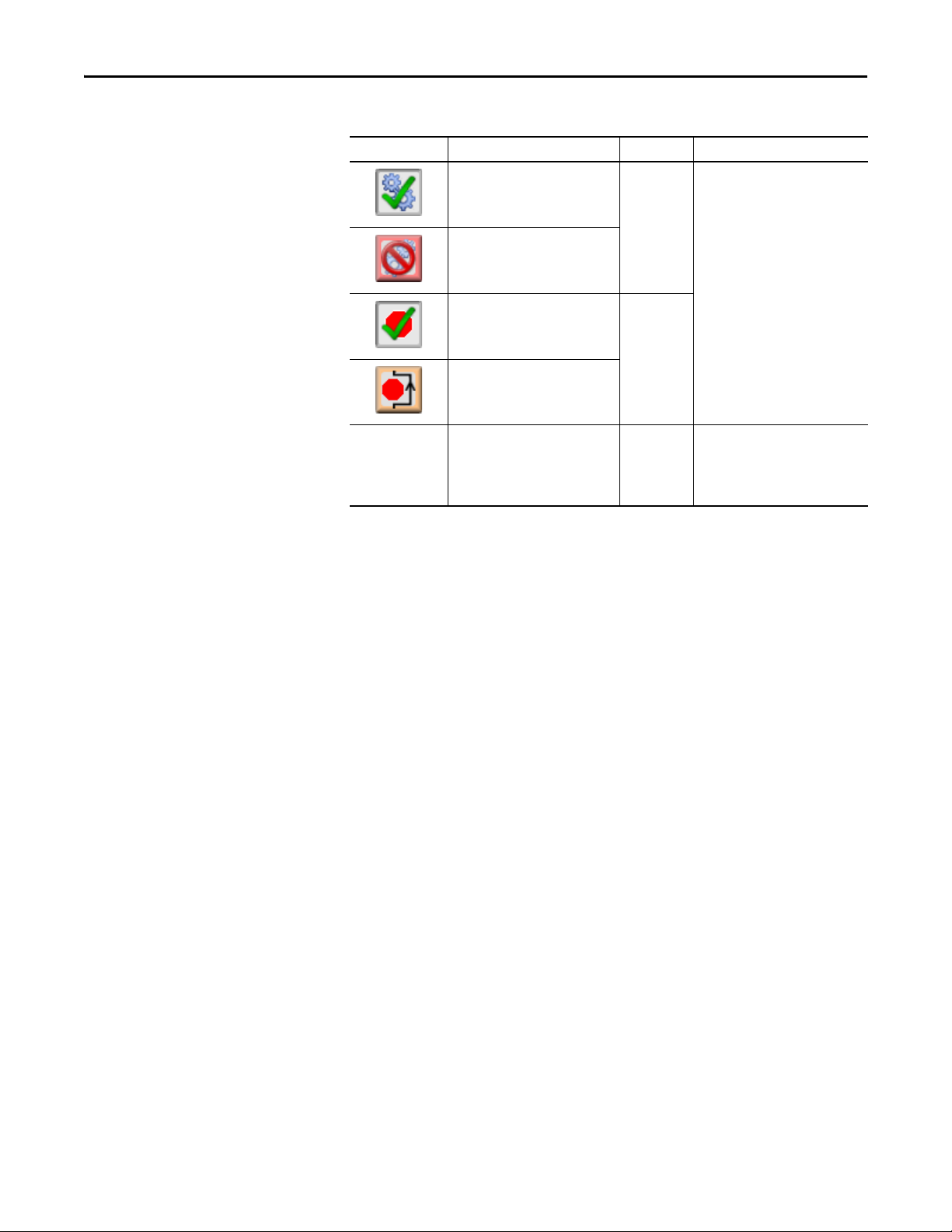
PowerFlex 6000 Drive (P_PF6000)
Table 13 - M aintenan ce Tab Desc ription
Function Ac tion Security Configuration Parameters
Click to enable drive. Equipment
Maintenance
(Code C)
Click to disable drive.
None
In Override Mode,
bypass inter locks
and Permissives
that can be
bypassed
Click to enable checking of all
interlocks and permissives.
Click to bypass checking of
bypassable interlocks and
permissives.
Check to have the bypassable
interlocks and permissives bypassed
in Override mode.
Disable
Alarms
Bypass
Permissives
and Interlocks
(Code H)
Engineering
Confi guration
(Code E)
Cfg_OvrdPermIntlk
46 Rockwell Automation Publication SYSLIB-RM057A-EN-P - January 2017
Page 47
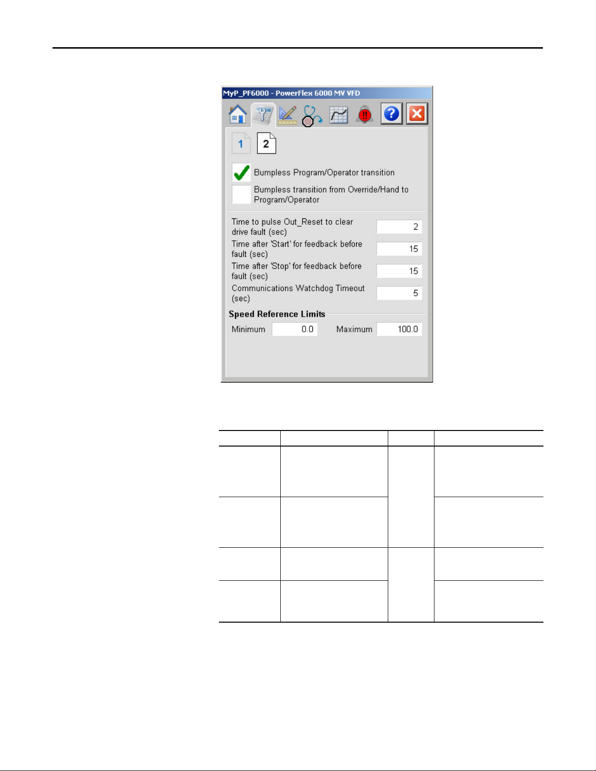
Maintenance Tab Page 2
PowerFlex 6000 Drive (P_PF6000)
The following table shows the functions on the Maintenance tab page 2.
Table 14 - Maintenance Tab Page 2 Description
Function Ac tion Security Configuration Parameters
Bumpless Program/
Operator transition
Bumpless transition
from Override/Hand
to Program/
Operator
Time to p ulse
Out_Reset to clear
drive fault (sec)
Time after ‘Start’ for
feedback before
fault (sec)
Check to have program settings, such
as Speed Reference, track operator
settings in Operator mode, and have
operator settings track Program
Settings in Program mode.
Check to have the Program and
Operator Speed Reference track the
Override Speed Reference in Override
mode or the actual speed in Hand
mode.
Type the amount of time to hold
Out_Reset true to reset a drive fault
when a reset command is received.
Type the amount of time to allow for
the drive’s run feedback to confirm
that the drive has started before
raising a Fail to Start alarm.
Equipme nt
Maintenance
(Code C)
Confi guration
& Tuning
Maintenance
(Code D)
Cfg_SetTrack
Cfg_SetTrackOvrdHand
Cfg_ResetPulseT
Cfg_FailToStartT
Rockwell Automation Publication SYSLIB-RM057A-EN-P - January 2017 47
Page 48

PowerFlex 6000 Drive (P_PF6000)
Table 14 - Maintenance Tab Page 2 Description
Function Ac tion Security Configuration Parameters
Time after ‘Stop’ for
feedback before
fault (sec)
Communications
Watc hdog Time out
(sec)
Speed Reference
Limits (Minimum
and Maximum)
Type the amount of time to allow for
the drive’s run feedback to confirm
that the drive has stopped before
raising a Fail to Stop alarm.
Type the maximum time (in seconds)
to allow to detect a communication
timeout.
Typ e th e cl ampi ng limits for the
speed reference. If a speed reference
outside this range is entered, the
speed is clamped at these limits and
Sts_SpeedLimited is asser ted.
Confi guration
and Tuning
Maintenance
(Code D)
Cfg_FailToStopT
Cfg_WatchdogT
• Cfg_MaxSpdRef
• Cfg_MinSpdRef
48 Rockwell Automation Publication SYSLIB-RM057A-EN-P - January 2017
Page 49

PowerFlex 6000 Drive (P_PF6000)
Feedback Engineering
Range
Speed Reference
Engineering Range
Engineering Tab
The Engineering tab provides access to device configuration parameters and
ranges, options for device and I/O setup, displayed text, and
faceplate-to-faceplate navigation settings, and for initial system commissioning
or later system changes.
The Engineering tab is divided into four pages.
Engineering Tab Page 1
Page 1 of the Engineering tab lets you can configure the speed scaling for
the drive.
The following table lists the functions on the Engineering tab page 1.
Table 15 - Engineering Tab 1 Description
Function Action Security Configuration Parameters
Scaled
(maximum)
Scaled
(minimum)
Rockwell Automation Publication SYSLIB-RM057A-EN-P - January 2017 49
Type an engineering unit value for
the maximum feedback from
the drive.
Type an engineering unit value for
the minimum speed feedback from
the drive. (This value is usually zero.)
Engineering
Confi guration
(Code E)
Cfg_SpeedFdbkEUMax
Cfg_SpeedFdbkEUMIN
Page 50

PowerFlex 6000 Drive (P_PF6000)
IMPORTANT
Table 15 - Engineering Tab 1 Description
Function Action Security Configuration Parameters
EU
(maximum)
EU
(minimum)
Type an engineering unit value for
the speed reference maximum sent
to the drive.)
Type an engineering unit value for
the speed reference maximum sent
to the drive.)
Engineering
Confi guration
(Code E)
Cfg_SpeedRefEUMax
Cfg_SpeedRefEUMin
Mode Configuration Display
This display lets you select the default mode for the object by selecting the
appropriate mode.
If no mode is being requested, changing the default mode changes the mode
of the instruction.
You must have FactoryTalk View security code E to select the default mode on
this display.
50 Rockwell Automation Publication SYSLIB-RM057A-EN-P - January 2017
Page 51

Engineering Tab Page 2
PowerFlex 6000 Drive (P_PF6000)
The following table lists the functions on the Engineering tab page 2.
Table 16 - Engineering Tab Page 2 Description
Function Action Security Configuration Parameters
Click to navigate to the Mode
Configuration display.
Description Type the device description to show
Label Type the label to show on the Graphic
Tag Type the tag name to show on the
Clear Program
commands upon
receipt
on the faceplate title bar.
Symbol.
faceplate title bar and in the Tooltip.
IMPORTANT: Pausing the mouse
over these fields displays a tool tip
with the configured Logix tag/path.
Check to use Edge-triggered Program
Commands (default).
Clear the checkbox to use
Level-triggered Program Commands.
None See Mode Configuration display on
Engineering
Confi guration
(Code E)
page 50
Cfg_Desc
Cfg_Label
Cfg_Tag
Cfg_PCmdClear
Rockwell Automation Publication SYSLIB-RM057A-EN-P - January 2017 51
Page 52

PowerFlex 6000 Drive (P_PF6000)
Table 16 - Engineering Tab Page 2 Description
Function Action Security Configuration Parameters
Operator command
resets fault
Enable navigation
to permissive object
Enable navigation
to interlock object
Check to permit the Operator Start or
Stop command to reset any previous
faults (I/O Fault, Fail to Start, Fail to
Stop, Interlock Trip), then start or
stop the motor.
Clear this checkbox if a reset is
required to clear faults.
Check if a permissive object is
connected to Inp_Perm. The
Permissive indicator becomes a
button that opens the Permissive
faceplate.
IMPORTANT: The name of the
Permissive object in the controller
must be the object name with the
suffix ‘_Perm’. For example, if your
P_PF6000 object has the name ‘Drive
123’, then its Permissive object must
be named ‘Drive 123_Perm’.
Check if an interlock object is
connected to Inp_Intlk. The Interlock
indicator becomes a button that
opens the Interlock faceplate.
Engineering
Confi guration
(Code E)
Cfg_OCmdResets
Cfg_HasPermObj
Cfg_HasIntlkObj
Enable navigation
to restart inhibit
object
Enable navigation
to run time object
IMPORTANT: The name of the
Interlock object in the controller must
be the object name with the suffix
‘_Intlk’. For example, if your
P_PF6000 object has the name ‘Drive
123’, then its Interlock object must be
named ‘Drive 123_Intlk’.
Check if a restart inhibit object is
connected. The button that opens the
Restart Inhibit faceplate appears.
IMPORTANT: The name of the
Restart Inhibit object in the controller
must be the object name with the
suffix ‘_ResInh’. For example, if your
P_PF6000 object has the name ‘Drive
123’, then its Restart Inhibit objec t
must be named ‘Drive 123_ResInh’.
Check if a runtime object is
connected. The button that opens the
Run Time faceplate appears.
IMPORTANT: The name of the Run
Time object in the controller must be
the object name with the suffix
‘_RunTime’. For example, if your
P_PF6000 object has the name ‘Drive
123’, then its Run Time object must
be named ‘Drive 123_RunTime’.
Cfg_HasResInhObj
Cfg_HasResInhObj
52 Rockwell Automation Publication SYSLIB-RM057A-EN-P - January 2017
Page 53

Engineering Tab Page 3
PowerFlex 6000 Drive (P_PF6000)
The following table shows the functions on the Engineering tab page 3.
Table 17 - Engineering Tab Page 3 Description
Function Ac tion Sec urity Configuration Parameters
Stop Drive:
On I/O Fault
Stop Drive:
On Fail to Start
Stop Drive:
On Interlock Trip
Check to stop the drive if an I/O Fault
is detected.
Clear the box to show only the I/O Fault
Status/Alarm and not stop the drive if
an I/O Fault is detected.
This occurs when the bit is:
• ‘On’ indicates a motor fail to start is
detected, the motor is stopped. A
reset is required before another
start c an be attempted.
• ‘Off ’indicates a motor fail to start is
detected, the instruction sets only
the Sts_FailToStart status (and the
Alm_FailToStart alarm, if so
configured). The outputs are not
changed, so the instruction
continues to start the motor.
The motor always stops on an interlock
trip. This item cannot be unchecked. It
is displayed as a reminder that the
Interlock Trip function always trips
the motor.
Engineering
Configuration
(Code E )
Cfg_ShedOnIOFault
Cfg_ShedOnFailToStart
None
Rockwell Automation Publication SYSLIB-RM057A-EN-P - January 2017 53
Page 54

PowerFlex 6000 Drive (P_PF6000)
Table 17 - Engineering Tab Page 3 Description
Function Ac tion Sec urity Configuration Parameters
Speed Reference Operator Keeps
Control in Progr am
Mode
Speed Reference Program Keeps
Control in Operator
Mode
‘Start’ & ‘Stop’
Commands Operator Keeps
Control in Progr am
Mode
‘Start’ & ‘Stop’
Commands Program Keeps
Control in Operator
Mode
Check to keep control of the drive
Speed Reference with the Operator,
even if the instruction is in Program
mode.
Clear this box to have control of the
drive Speed Reference follow the
Instruction mode.
Check to keep control of the drive
Speed Reference with the Program,
even if the instruction is in Operator
mode.
Clear this box to have control of the
drive Speed Reference follow the
Instruction mode.
Check to keep the drive Start, Stop, and
Jog (if used) commands with the
Operator, even if the instruction is in
Program mode.
Clear this box to have control of
the drive Start and Stop follow
Instruction mode.
Check to keep control of the drive Start
and Stop commands with the Program,
even if the instruction is in Operator
mode.
IMPORTANT: Clear this box to have
control of the drive Start and Stop
follow Instruction mode.
Engineering
Configuration
(Code E )
Cfg_OperKeep.0
Cfg_ProgKeep.0
Cfg_OperKeep.1
Cfg_ProgKeep.1
54 Rockwell Automation Publication SYSLIB-RM057A-EN-P - January 2017
Page 55
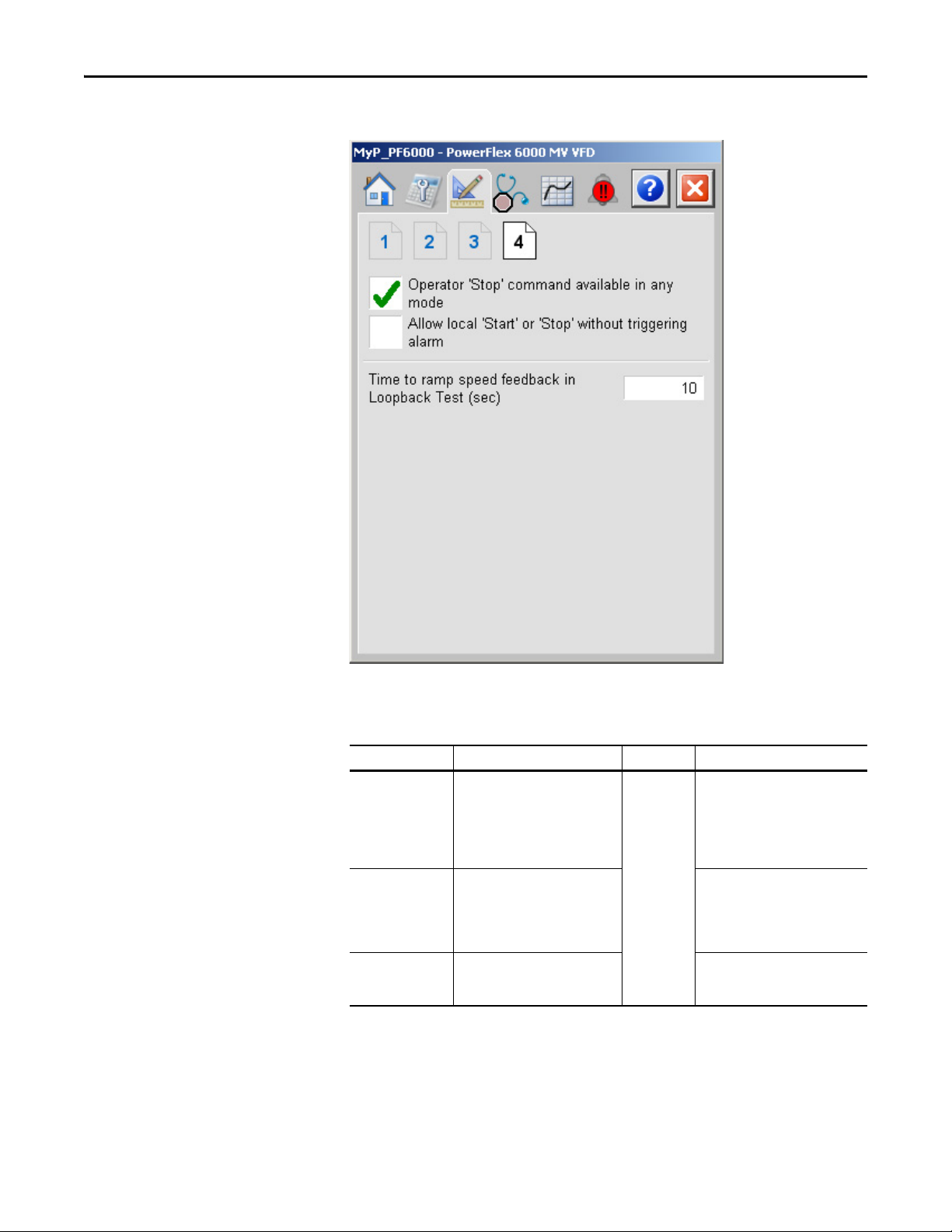
Engineering Tab Page 4
PowerFlex 6000 Drive (P_PF6000)
The following table shows the functions on the Engineering tab page 4.
Table 18 - Engineering Tab Page 4 Description
Function Action Security Configuration Parameters
Operator ‘Stop’
command available
in any mode
Allow local ‘Start’ or
‘Stop’ without
triggering alarm
Time to ramp speed
feedback in
Loopback Test (sec)
Check (= 1) so that the OCmd_Stop
has priority and is accepted at any
time.
Clear this checkbox (= 0) so that the
OCmd_Stop works only in Operator
or Maintenance mode.
Check (= 1) to allow local start/stop
without an alarm.
Clear this checkbox (= 0) to
start/stop from the HMI or program
only.
Enter the time, in seconds, to ramp
speed feedback when in Simulation.
Engineering
Maintenance
(Code E)
Cfg_OperStopPrio
Cfg_AllowLocal
Cfg_SimRampT
Rockwell Automation Publication SYSLIB-RM057A-EN-P - January 2017 55
Page 56

PowerFlex 6000 Drive (P_PF6000)
Diagnostics Tab
This tab is divided into three pages. Each page provides you with diagnostic
feedback on the drive.
56 Rockwell Automation Publication SYSLIB-RM057A-EN-P - January 2017
Page 57

PowerFlex 6000 Drive (P_PF6000)
Speed Feedback
Trends Tab
This tab shows trend charts of key device data over time. These faceplate trends
provide a quick view of current device performance to supplement, but not
replace, dedicated historical or live trend displays.
Rockwell Automation Publication SYSLIB-RM057A-EN-P - January 2017 57
Page 58

PowerFlex 6000 Drive (P_PF6000)
Reset and Acknowledge All
Alarms Command Button
Alarm Names
Alarm Acknowledge
Command Button
Alarms Tab
The Alarms tab displays each configured alarm for the P_PF6000 instruction.
The icon on the tab for the alarms page changes color based on the current active
alarms. A blinking alarm icon indicates that one or more alarms must be
acknowledged or the device must be reset.
Click an alarm name to open the P_Alarm faceplate for that alarm. From the
P_Alarm faceplate, you can configure and perform additional operations on
the alarm.
If an alarm is active, the panel behind the alarm changes color to match the
severity of the alarm. The color of the bell icon at the top of the faceplate shows
the severity of the highest active alarm, and the icon blinks if any alarm is
unacknowledged or requires reset.
Table 19 - Alarm Severity Colors
Color Definition
Magenta Urgent
Red High
Yel l ow Me d iu m
Blue Low
White (bell icon) Alarm has cleared but is unacknowledged
Background (Light Gray) No alarm
58 Rockwell Automation Publication SYSLIB-RM057A-EN-P - January 2017
Page 59

PowerFlex 6000 Drive (P_PF6000)
The following table shows the functions on the Alarms tab.
Table 20 - Alarms Tab De script ion
Function Ac tion Security
Alarm Name Click an alarm name to open the associated
P_Alarm faceplate.
Click to acknowledge the alarm. Acknowledge Alarms
Click to reset and acknowledge all alarms.
None
(Code F )
When the Reset and Acknowledge All Alarms button is enabled, the panel
behind the alarm blinks, indicating the alarm requires acknowledgement or reset.
The Alarm Acknowledge button is enabled if the alarm requires
acknowledgment. Click the button with the check mark to acknowledge the
alarm.
See Rockwell Automation Library of Process Objects: Common Alarm Block
(P_Alarm) Reference Manual, publication SYSLIB-RM002
, for
more information.
Rockwell Automation Publication SYSLIB-RM057A-EN-P - January 2017 59
Page 60
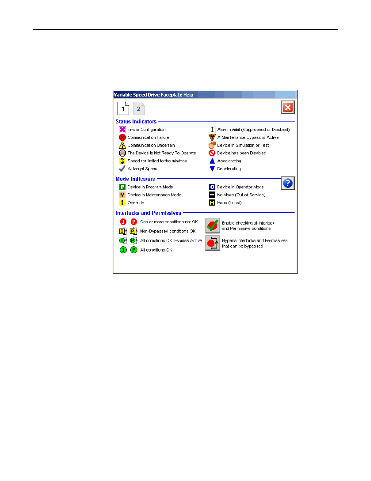
PowerFlex 6000 Drive (P_PF6000)
PowerFlex Drive Faceplate Help
The Faceplate Help is divided into two pages.
Faceplate Help Page 1
60 Rockwell Automation Publication SYSLIB-RM057A-EN-P - January 2017
Page 61
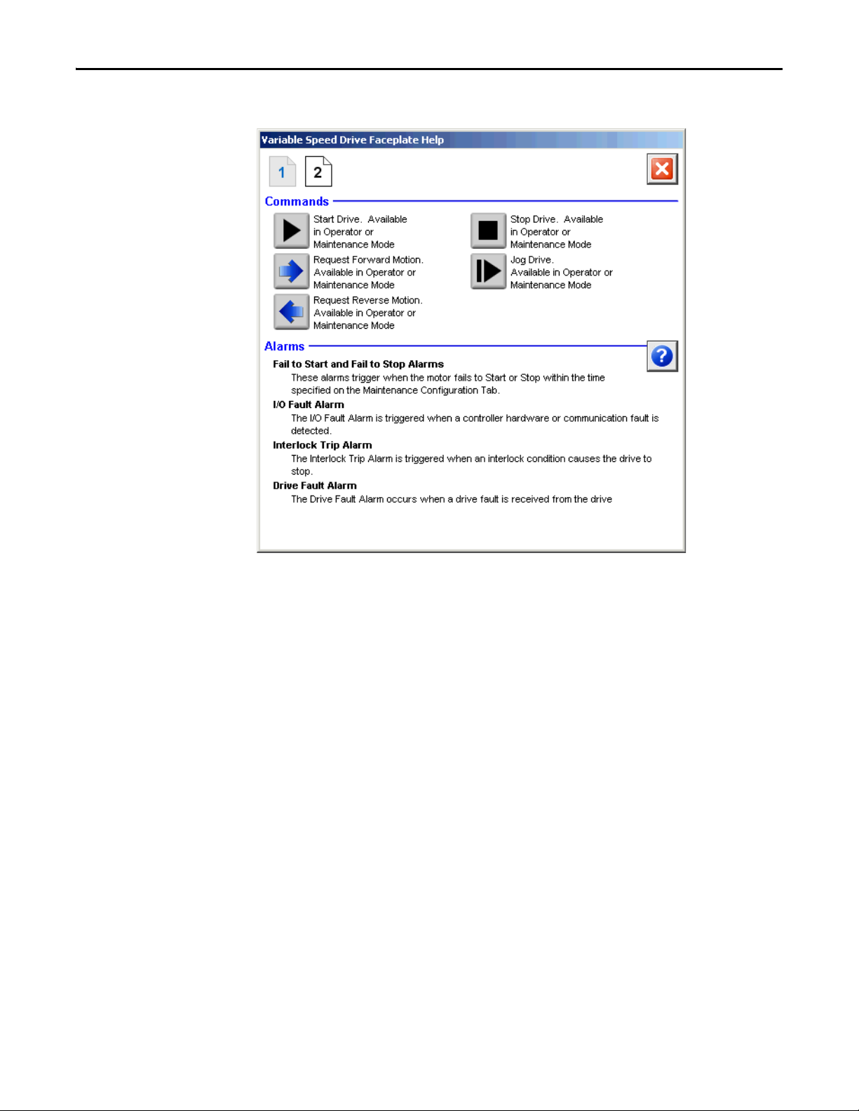
Faceplate Help Page 2
PowerFlex 6000 Drive (P_PF6000)
Rockwell Automation Publication SYSLIB-RM057A-EN-P - January 2017 61
Page 62

PowerFlex 6000 Drive (P_PF6000)
Notes:
62 Rockwell Automation Publication SYSLIB-RM057A-EN-P - January 2017
Page 63

Page 64

Rockwell Automation Support
Rockwell Otomasyon Ticaret A.Ş., Kar Plaza İş Merkezi E Blok Kat:6 34752 İçerenköy, İstanbul, Tel: +90 (216) 5698400
Rockwell Automation provides technical information on the Web to assist you in using its products.
At http://www.rockwellautomation.com/support
software service packs. You can also visit our Support Center at https://rockwellautomation.custhelp.com/
updates, support chats and forums, technical information, FAQs, and to sign up for product notification updates.
In addition, we offer multiple support programs for installation, configuration, and troubleshooting. For more
information, contact your local distributor or Rockwell Automation representative, or visit
http://www.rockwellautomation.com/services/online-phone
Installation Assistance
If you experience a problem within the first 24 hours of installation, review the information that is contained in this
manual. You can contact Customer Support for initial help in getting your product up and running.
United States or Canada 1.440.646.3434
Outside United States or Canada Use the Wor ldwi de Lo cato r
Rockwell Automation representative.
at http://www.rockwellautomation.com/rockwellautomation/support/overview.page, or contact your local
New Product Satisfaction Return
you can find technical and application notes, sample code, and links to
for software
.
Rockwell Automation tests all of its products to help ensure that they are fully operational when shipped from the
manufacturing facility. However, if your product is not functioning and needs to be returned, follow these procedures.
United States Contact your distributor. You must provide a Customer Support case number (call the phone number above to obtain one) to your
Outside United States Please contact your local Rockwell Automation representative for the return procedure.
distributor to complete the return process.
Documentation Feedback
Your comments will help us serve your documentation needs better. If you have any suggestions on how to improve this
document, complete this form, publication RA-DU002
Rockwell Automation maintains current product environmental information on its website at
http://www.rockwellautomation.com/rockwellautomation/about-us/sustainability-ethics/product-environmental-compliance.page
, available at http://www.rockwellautomation.com/literature/.
.
Publication SYSLIB-RM057A-EN-P - January 2017
Copyright © 2017 Rockwell Auto mation, Inc. All rights reserved. Pr inted in the U.S.A.
 Loading...