

Page 1
Triguard SC300E
PDC24 / PAC
Chassis Power Supplies
(PDC24 / PAC)
Issue 3
INTRODUCTION
PURPOSE
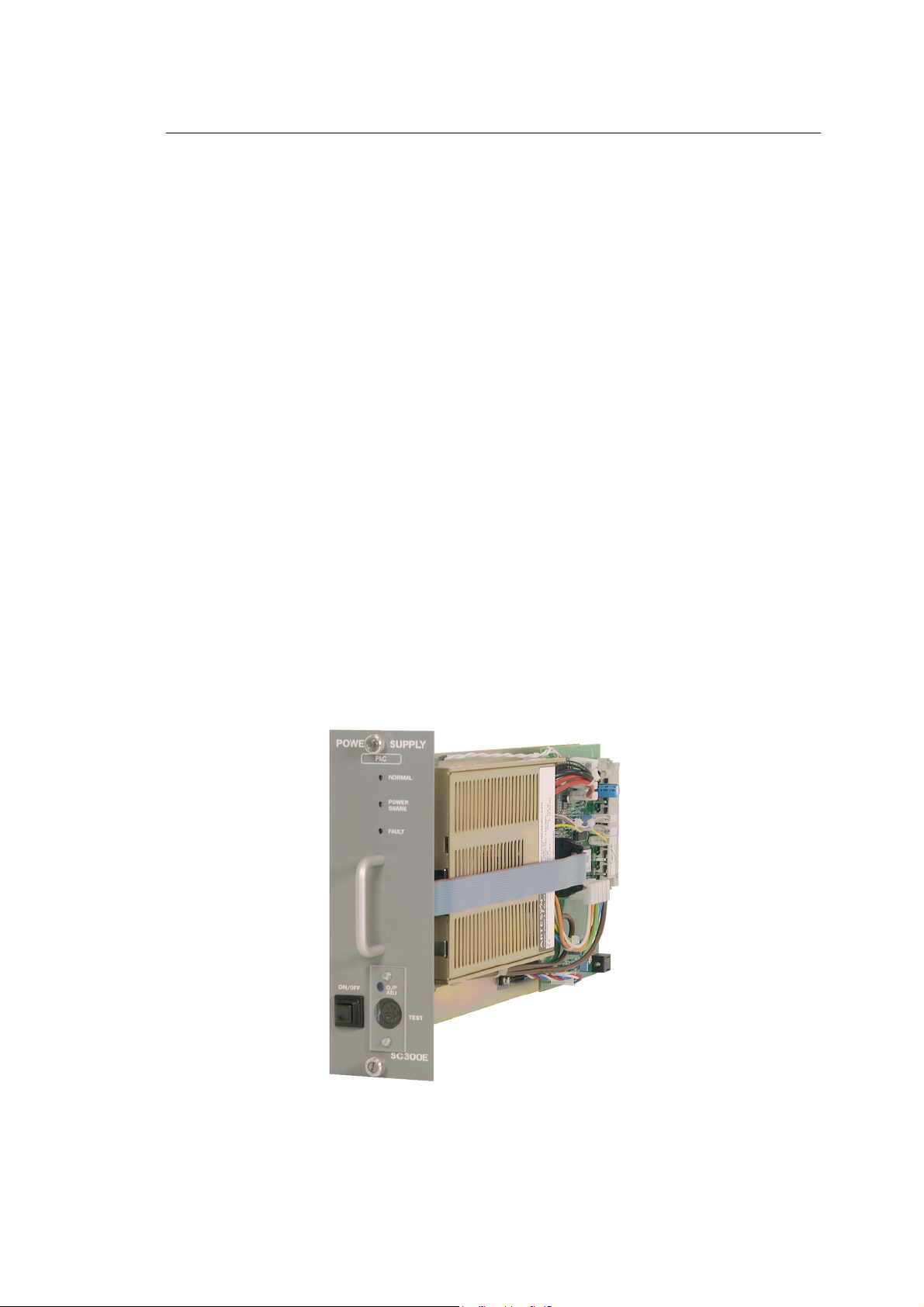
Two Power Supply Units (PSUs) provide a dual-redundant source of 5.4Vand 12Vdc onto the
backplane for the modules mounted in a SC300E chassis. The PSUs are mounted one above
the
other in the left hand side of the chassis as shown.
Each PSU has a fault warning system and a power sharing system. The power sharing system
operates
other
when both PSUs are working. Either PSU has the capacity to power the system if the
one fails.
October 2005
Th
e PSUs operate from the following supplies detailed in Table 1-1:
This document is intended to provide a general understanding of the function of the PAC and
PDC24, sufficient to enable basic maintenance operations to be effected in the field.
Figure 1-1. PDC24 /
008-5098
PAC General view
Page 2

2
PDC24
/
PAC
October
2005–
Iss
ue 3
Triguard
SC300E
ASSOCIATED DOCUMENTATION
Reference
008-5097
Specification
Nominal input voltage
Input voltage range
Inputfrequency range
Input power
Output power
Outputs
Output hold up time
Inrush current
Title
Model
PDC24
Chassis User Manual
24Vdc
20 to 36Vdc
Not applicable
200W
145W
5.4Vdc @ 18A
12Vdc @ 4A
20 mS
170A, 1.5ms time constant
PAC
110/230Vac Auto ranging
92 to 132Vac or
184 to 264Vac
45 to 65Hz
235W
175W
5.4Vdc @ 23A
12Vdc @ 4A
20mS
30A , 4ms time constant
Isolation
Indicators
Alarm contact ratings
Overall size (mm)
Overall size (inches)
Weight
2.5kVdc
Green –
Yellow –
Red –
175V, 0.25A
420H x 200L x 68W
16.5H x 7.87L x 2.67W
2.3kg
Table 1-1. PDC24/PDC data
Normal
Power Share
Fault
3kVac
Green –
Yellow –
Red -
175V, 0.25A
420H x 200L x 68W
16.5H x 7.87L x 2.67W
2.3kg
Normal
Power Share
Fault
Page 3

PDC24
/
PAC
October
2005–
Issue 3
3
Tri
guard
SC300E PDC24 / PAC Chassis Power Supplies
ENVIRONMENTAL SPECIF
The maximum ambient temperature measured at the hottest point within the Triguard system
shall
not be greater than 60 degrees centigrade.
Temp
erature operating:
Temperature
Humidity:
EMC/RFI
Vibration/Shock:
Certification:
General Certification: Ref. SC300E TMR Product Guide (ref 008-5209).
storage:
Immunity:
ICATIONS
+5°C to +60°C
-
25°C to +70°C
5% to 95% non-condensing at ambient < 40°C
Tested and certified to IEC 1131-Part 2 1994
Tested and certified to IEC 1131-Part 2 1994
TRANSPORT AND HANDLING
The PSU must be transported and stored in its original packing material which should be
retained for this purpose.
Page 4

4
PDC24
/
PAC
October
2005–
Iss
ue 3
Triguard
SC300E
TECHNICAL DESCRIPTIO
N
PHYSICAL
The PSU comprises a front plate mounted at right angles to a chassis plate. All the user
controls and indicators are mounted on the front plate as shown in Figure 1-1.
The chassis plate supports three main items:
• Power supply unit: A self-contained switch-mode power supply unit (SMPS).
•
• PSU interface PCB: Contains the power share and fault alarm circuits. Interfaces these
A ribbon cable connects the front panel PCB to the SMPS. A mechanical stop fitted to the AC
system chassis power supply slots (marked AC STUD) prevents the insertion of a PDC24 into
a PAC slot.
Front panel PCB: Contains printed wiring and physical support for the controls and
indicators that are viewed and accessed from the front panel.
circuits
and the SMPS to the SC300E chassis backplane via connector PL3.
Page 5

PDC24
/
PAC
October
2005–
Issue 3
5
Tri
guard
SC300E PDC24 / PAC Chassis Power Supplies
Figure 2-1 PSU Layout and dimensions
Page 6

6
PDC24
/
PAC
October
2005–
Iss
ue 3
Triguard
SC300E
EXTERNAL CONNECTIONS
Chassis backplane connector PL3
The chassis backplane connector details are given in Table 2-1.
DIN41612 type H15 male connector. SK1 acts as a guide to prealign connector PL3 with its
mating socket when the PSU is inserted into its slot.
Pin
4
6
8
10
12
14
Table 2-1. Backplane connector pinouts
5V return
5V return
+5V output
+5V output
5V reutrn sense
5V +ve sense
Signal
16
18
20
22
24
26
28
30
32
12V return
+12V output
Power fail output
Power share
Alarm contact COM
Alarm contacts NO
Ac(N) or dc –ve input
AC(I) or dc +ve input
Earth (mates first)
Page 7

PDC24
/
PAC
October
2005–
Issue 3
7
Test connector
Tri
guard
SC300E PDC24 / PAC Chassis Power Supplies
The 8-way 270º DIN socket located on the front panel. The connector pinout details are given in
Table 2-2.
Table 2-2. Test connector pinouts
PIN
1
2
3
4
5
6
7
8
5V return at SMPS
12V +ve output at SMPS
5V +ve output at SMPS
+5V return at backplane
Power share line
5V supply –
5V supply +ve sense
Power fail interrupt
Signal
ve sense
Figure 2-2 Test connector pin number location
Page 8

8
PDC24
/
PAC
October
2005–
Iss
ue 3
Triguard
SC300E
THEORY OF OPERATION
Main power flow
The 5.4V output allows for a drop of about 0.4V across the auctioneering diodes in each
module supplied.
The output voltage is fed back to the SMPS control circuits via the +ve and -ve
The SMPS then compensates for any voltage drop along the power supply lines by increasing
its output voltage. The rated output voltage is thus present at the load rather than at the PSU
output terminals. The -ve
The 5V supply current sensor is a 0.005-ohm resistance formed by two resistors in parallel.
The voltage developed across the resistors is used as a measure of output current by the
power share and fa
Various system voltages are connected by current limiting resistors to individual pins of the
test
socket on the front panel. The ‘current limiters’ protect the system against accidental
short circuits on any of the test socket pins.
Plant shutdown -
sense input to the SMPS is modified by the power share system.
ult alarm circuits.
Adjusting the power supplies in a running system could result in a
W
ARNING
plant shutdown.
sense lines.
Power share system
The power share control circuit accepts inputs from the 5V supply current sensor, the +ve and
-ve
sense lines, the output adjustment trimmer (O/P ADJ) on the front panel, and the power
share line. It drives the power share line, the power share LED on the front panel, and the
voltage on the -ve
sense line input to the SMPS.
Normally the voltage at the -ve
from the backplane. When the power share control circuit detects that an increase in output
current is required to maintain power balance, the -ve
voltage
output voltage.
between the +ve and -ve sense lines is now greater. The SMPS then increases its
sense input to the SMPS is close to that on the -ve
sense SMPS voltage drops, so that the
sense line
Fault alarm system
The power fail output from the SMPS switches from logic high to low just before the SMPS
output fails (i.e. to give advance warning following a failure of the ac/dc input supply). The fault
alarm circuits de-energise the fault relay in response to:
• The power fail signal
• An input from a 70ºC thermal cut-out on the SMPS
• An undervoltage output condition detected on the +ve and -ve
A set of changeover cont
pair
of
relay contacts is available to operate an external alarm. These contacts open under fault
conditions.
acts controls the Fault and Normal LEDs on the front panel. Another
sense lines
Page 9

PDC24
/
PAC
October
2005–
Issue 3
9
Tri
guard
SWITCHES AND INDICATORS
SC300E PDC24 / PAC Chassis Power Supplies
All user interface is via the front panel (Figure 2-3).
Table 2-3. Front panel facilities
LED Indicator
Normal LED (green)
Power Share LED (yellow) Illuminates to indicate that power sharing is in balance. It can
Fault LED (red)
TEST
ON/OFF
O/P Adi
Indication
Illuminates to indicate normal operation
extinguish
Balance
tests).
NOTE: If one PSU is removed, the Power share LED on the
remaining PSU illuminates.
Illuminates to indicate an over temperature or undervoltage fault
condition
8-way 270º DIN socket. Use as described in XRefColorection
functionality tests, Default ¶ Font. A mating connector is
available
3A (PAC)/10A (PDC24) circuit breaker and ON/OFF push switch
for
supply voltage.
Screwdriver adjustment of current sharing/output voltage.
if
the other PSU supplies about 1.3A more current.
can be adjusted (see Section 3.3 Field functionality
free of charge.
The following facilities are provided:
Page 10

10
PDC24
/
PAC
October
2005–
Iss
ue 3
Triguard
SC300E
Figure 2-3 PDC24/PAC Front panel
Page 11

PDC24
/
PAC
October
2005–
Issue 3
11
Tri
guard
SC300E PDC24 / PAC Chassis Power Supplies
SERVICING
SCOPE
The PSUs have no field replaceable parts. Faulty units should be returned for repair.
CONFIGURATION
No configurable links.
FIELD FUNCTIONALITY TESTS
The 12V supply is not calibrated. Set up the 5V supply as follows. For each test use a digital
voltmeter
Output voltage (5V)
Measure across pins 6 and 7. The voltage should be 5.4V ±0.01V.
Output voltage (12V)
across the relevant pair of pins on the 8-way DIN socket.
Measure across pins 1 and 2. The voltage should be within the range 11.5V to 12.5V.
Output current (5V)
Measure the voltage between pins 1 and 4. This should be proportional to the current supplied
by the PSU at 0.005 Volts per Amp. The current supplied will depend on the configuration of
modules within the system.
SMPS Output voltage (5V)
Measure the voltage between pins 3 and 6. This should not exceed 5.8V. A higher value
(nominally 6.3V) may initiate an overvoltage trip.
Power share line
Measure the voltage between pins 1 and 5. The voltage will depend on the currents being
provided by both power supplies. It should not exceed 4.0V at maximum current.
Power fail interrupt
This can be monitored on pin 8. It is a logic output that is normally pulled up resistively to +5V,
but
is
pulled low if the ac/dc input supply fails.
Page 12

12
PDC24
/
PAC
October
2005–
Iss
ue 3
Triguard
SC300E
Front panel LEDs
Check that the green LED (Normal) is on and the red LED (Fault) is off. A fault condition can
be due to:
• A failure of the ac/dc input supply
• An output below 5.1V
• An SMPS over temperature condition.
Check that the yellow LED (Power Share) is on. It extinguishes when the other PSU is
supplying the greater current.
If the Power Share LED is extinguished and no fault is indicated on either PSU, there could be an
imbalance in output between the two PSUs.
CALIBRATION
Calibration is not required in normal operation.
Calibration of PSUs must not be performed on a running system.
Use the front panel trimmers to adjust the balance until both Power Share LEDs are
illuminated.
PSUs are power sharing to any extent. If this voltage is being measured while adjusting a
trimmer, the other PSU will need to be switched off (or short circuit pins 1 and 5 of one test
socket to disable current sharing) to see any effect on the meter. Adjust both PSUs until the
voltage
The voltage between pins 6 and 7 of both test sockets will be the same if the
is
the same (normally 5.4V ± 0.01V).
Page 13

PDC24
/
PAC
October
2005–
Issue 3
13
Tri
guard
SC300E PDC24 / PAC Chassis Power Supplies
SERVICE SUPPORT
SPARE PARTS
Spare parts and technical advice can be obtained from your local area office.
 Loading...