

Rockwell Automation PanelView Plus, PanelView Plus 700, PanelView Plus 1250, PanelView Plus 1000, PanelView Plus 1500 User Manual
...Page 1

PanelView Plus Terminals
User Manual
Catalog Number 2711P
400, 600, 700, 1000, 1250, 1500
Term in als
Page 2
Important User Information
Solid state equipment has operational characteristics differing from those of electromechanical equipment. Safety Guidelines
for the Application, Installation and Maintenance of Solid State Controls (publication SGI-1.1 available from your local
Rockwell Automation sales office or online at http://literature.rockwellautomation.com
between solid state equipment and hard-wired electromechanical devices. Because of this difference, and also because of the
wide variety of uses for solid state equipment, all persons responsible for applying this equipment must satisfy themselves
that each intended application of this equipment is acceptable.
In no event will Rockwell Automation, Inc. be responsible or liable for indirect or consequential damages resulting from the
use or application of this equipment.
The examples and diagrams in this manual are included solely for illustrative purposes. Because of the many variables and
requirements associated with any particular installation, Rockwell Automation, Inc. cannot assume responsibility or liability
for actual use based on the examples and diagrams.
No patent liability is assumed by Rockwell Automation, Inc. with respect to use of information, circuits, equipment, or
software described in this manual.
Reproduction of the contents of this manual, in whole or in part, without written permission of Rockwell Automation, Inc., is
prohibited.
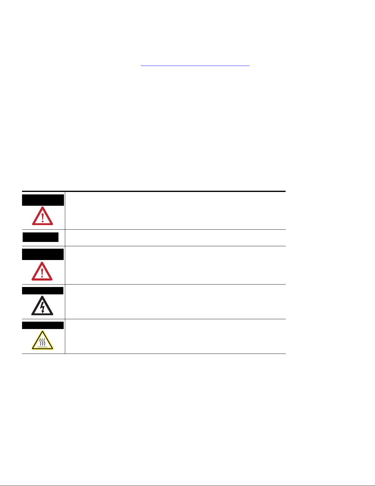
Throughout this manual, when necessary, we use notes to make you aware of safety considerations.
) describes some important differences
WARNING
Identifies information about practices or circumstances that can cause an explosion in a
hazardous environment, which may lead to personal injury or death, property damage, or
economic loss.
IMPORTANT
ATTENTION
Identifies information that is critical for successful application and understanding of the product.
Identifies information about practices or circumstances that can lead to personal injury or death,
property damage, or economic loss. Attentions help you identify a hazard, avoid a hazard, and
recognize the consequence
SHOCK HAZARD
Labels may be on or inside the equipment, for example, a drive or motor, to alert people that
dangerous voltage may be present.
BURN HAZARD
Labels may be on or inside the equipment, for example, a drive or motor, to alert people that
surfaces may reach dangerous temperatures.
Allen-Bradley, Rockwell Automation, and TechConnect are trademarks of Rockwell Automation, Inc.
Trademarks not belonging to Rockwell Automation are property of their respective companies.
Page 3

Summary of Changes
The information below summarizes the changes to this manual since
the last revision.
Revision bars, as shown in the margin, identify updated information.
This document includes the following changes.
Topic Page
Corrected touchscreen stylus tip radius 15, 16, 21, 22, 88
Added catalog numbers for marine-certified terminals and added
OEM option to catalog number configuration diagram
Updated series information for backlights 26
Added catalog number 2711P-RGB4 for antiglare overlay for
PanelView Plus 400 color keypad/touch terminal
Corrected temperature range around the terminals in Clearances 36
Corrected panel thickness range for lever position 1 38
Added battery type and disposal information 153
23, 25
27
Added footnotes to tables regarding maximum cable length for
DH-485 modules
Modified connector pinout diagram 176
Corrected wiring connections and pinouts in Remote I/O & DH+
depictions
Added message about maximum cable length for DH-485
modules
Added battery disposal information to Maintenance chapter 228
Added environmental information for Airborne Contaminants 230
Updated EMC and LVD Directives 232
168, 169, 170
178, 182, 183
178
3Publication 2711P-UM001I-EN-P - December 2008 3
Page 4

Summary of Changes
4 Publication 2711P-UM001I-EN-P - December 2008
Page 5

Table of Contents
Preface
Overview
Installation
Objectives. . . . . . . . . . . . . . . . . . . . . . . . . . . . . . . . . . . . . . . 9
Intended Audience . . . . . . . . . . . . . . . . . . . . . . . . . . . . . . . . 9
Parts List. . . . . . . . . . . . . . . . . . . . . . . . . . . . . . . . . . . . . . . . 9
Additional Resources. . . . . . . . . . . . . . . . . . . . . . . . . . . . . . 10
Software and Firmware Upgrades . . . . . . . . . . . . . . . . . . . . 10
Chapter 1
Chapter Objectives . . . . . . . . . . . . . . . . . . . . . . . . . . . . . . . 11
Software Support . . . . . . . . . . . . . . . . . . . . . . . . . . . . . . . . 11
PanelView Plus 400 and 600 Terminals . . . . . . . . . . . . . . . . 12
PanelView Plus 700 to 1500 Terminals . . . . . . . . . . . . . . . . . 17
Catalog Number Configuration. . . . . . . . . . . . . . . . . . . . . . . 23
PanelView Plus Product Components. . . . . . . . . . . . . . . . . . 23
Chapter 2
Chapter Objectives . . . . . . . . . . . . . . . . . . . . . . . . . . . . . . . 31
Hazardous Locations . . . . . . . . . . . . . . . . . . . . . . . . . . . . . . 31
Environment and Enclosure. . . . . . . . . . . . . . . . . . . . . . . . . 34
Outdoor Installation for High-bright Displays . . . . . . . . . . . . 34
Required Tools . . . . . . . . . . . . . . . . . . . . . . . . . . . . . . . . . . 36
Clearances . . . . . . . . . . . . . . . . . . . . . . . . . . . . . . . . . . . . . 36
Cutout Dimensions . . . . . . . . . . . . . . . . . . . . . . . . . . . . . . . 36
Mount the 400 or 600 Terminal in a Panel . . . . . . . . . . . . . . 37
Mount the 700 to 1500 Terminal in a Panel . . . . . . . . . . . . . 39
Product Dimensions . . . . . . . . . . . . . . . . . . . . . . . . . . . . . . 41
Power Connections
Configuration Mode
Chapter 3
Chapter Objectives . . . . . . . . . . . . . . . . . . . . . . . . . . . . . . . 47
Wiring and Safety Guidelines. . . . . . . . . . . . . . . . . . . . . . . . 47
Remove and Install the Power Terminal Block . . . . . . . . . . . 48
DC Power Connections . . . . . . . . . . . . . . . . . . . . . . . . . . . . 51
AC Power Connections . . . . . . . . . . . . . . . . . . . . . . . . . . . . 56
Reset the Terminals. . . . . . . . . . . . . . . . . . . . . . . . . . . . . . . 59
Chapter 4
Chapter Objectives . . . . . . . . . . . . . . . . . . . . . . . . . . . . . . . 61
Access Configuration Mode . . . . . . . . . . . . . . . . . . . . . . . . . 61
Load an Application . . . . . . . . . . . . . . . . . . . . . . . . . . . . . . 65
Run an Application . . . . . . . . . . . . . . . . . . . . . . . . . . . . . . . 66
Application Settings. . . . . . . . . . . . . . . . . . . . . . . . . . . . . . . 66
Terminal Settings . . . . . . . . . . . . . . . . . . . . . . . . . . . . . . . . 66
Configure Communications . . . . . . . . . . . . . . . . . . . . . . . . . 67
Configure Network Information . . . . . . . . . . . . . . . . . . . . . . 72
Configure Diagnostics . . . . . . . . . . . . . . . . . . . . . . . . . . . . . 76
Manage Files on the Terminal . . . . . . . . . . . . . . . . . . . . . . . 78
5Publication 2711P-UM001I-EN-P - December 2008 5
Page 6

Table of Contents
Windows CE .NET Operating
System
Modify Display Settings . . . . . . . . . . . . . . . . . . . . . . . . . . . . 81
Font Linking . . . . . . . . . . . . . . . . . . . . . . . . . . . . . . . . . . . . 85
Configure Keypad, Keyboard, or Mouse. . . . . . . . . . . . . . . . 86
Configure the Touch Screen . . . . . . . . . . . . . . . . . . . . . . . . 88
Configure Print Options. . . . . . . . . . . . . . . . . . . . . . . . . . . . 91
Configure Startup Options . . . . . . . . . . . . . . . . . . . . . . . . . . 93
Configure Startup Tests . . . . . . . . . . . . . . . . . . . . . . . . . . . . 99
View and Clear the System Event Log . . . . . . . . . . . . . . . . 101
Display Terminal Information . . . . . . . . . . . . . . . . . . . . . . 102
Display FactoryTalk View ME Station Information. . . . . . . . 104
Modify the Date, Time, or Time Zone . . . . . . . . . . . . . . . . 105
Modify Regional Settings . . . . . . . . . . . . . . . . . . . . . . . . . . 108
Chapter 5
Chapter Objectives . . . . . . . . . . . . . . . . . . . . . . . . . . . . . . 113
Windows CE .NET Architecture . . . . . . . . . . . . . . . . . . . . . 113
Windows CE .NET Programs . . . . . . . . . . . . . . . . . . . . . . 114
Windows CE .NET Operating System . . . . . . . . . . . . . . . . . 115
PanelView Plus CE Memory. . . . . . . . . . . . . . . . . . . . . . . . 119
Control Panel Applications . . . . . . . . . . . . . . . . . . . . . . . . 121
Install and Replace Components
Terminal Connections
Chapter 6
Chapter Objectives . . . . . . . . . . . . . . . . . . . . . . . . . . . . . . 141
Required Tools . . . . . . . . . . . . . . . . . . . . . . . . . . . . . . . . . 141
Precautions. . . . . . . . . . . . . . . . . . . . . . . . . . . . . . . . . . . . 141
Component Compatibility for PanelView Plus CE Terminals 142
Component Compatibility for PanelView Plus Terminals. . . 142
Install RAM or Internal CompactFlash. . . . . . . . . . . . . . . . . 143
Install or Replace the Logic Module . . . . . . . . . . . . . . . . . . 144
Install or Replace a Communication Module. . . . . . . . . . . . 147
Replace the Display Module . . . . . . . . . . . . . . . . . . . . . . . 151
Replace the Battery . . . . . . . . . . . . . . . . . . . . . . . . . . . . . . 153
Replace the Bezel . . . . . . . . . . . . . . . . . . . . . . . . . . . . . . . 155
Replace the Backlight . . . . . . . . . . . . . . . . . . . . . . . . . . . . 158
Remove the Product ID Label . . . . . . . . . . . . . . . . . . . . . . 162
Replace the Keypad Legend Inserts . . . . . . . . . . . . . . . . . . 162
Use an External CompactFlash Card. . . . . . . . . . . . . . . . . . 165
Chapter 7
Chapter Objectives . . . . . . . . . . . . . . . . . . . . . . . . . . . . . . 167
Wiring and Safety Guidelines. . . . . . . . . . . . . . . . . . . . . . . 167
Logic Controller Cable Charts . . . . . . . . . . . . . . . . . . . . . . 168
Communication Port Isolation . . . . . . . . . . . . . . . . . . . . . . 171
USB Ports . . . . . . . . . . . . . . . . . . . . . . . . . . . . . . . . . . . . . 172
Serial Connections. . . . . . . . . . . . . . . . . . . . . . . . . . . . . . . 173
6 Publication 2711P-UM001I-EN-P - December 2008
Page 7

Upgrade Firmware
Troubleshoot the System
Table of Contents
Ethernet Connections . . . . . . . . . . . . . . . . . . . . . . . . . . . . 176
DH-485/DH+/Remote I/O Module . . . . . . . . . . . . . . . . . . . 178
ControlNet Module . . . . . . . . . . . . . . . . . . . . . . . . . . . . . . 184
DeviceNet Module . . . . . . . . . . . . . . . . . . . . . . . . . . . . . . 187
Chapter 8
Chapter Objectives . . . . . . . . . . . . . . . . . . . . . . . . . . . . . . 193
Transfer Applications . . . . . . . . . . . . . . . . . . . . . . . . . . . . 193
Create an ActiveSync Connection. . . . . . . . . . . . . . . . . . . . 193
Firmware Upgrade Wizard. . . . . . . . . . . . . . . . . . . . . . . . . 195
Upgrade Firmware with a CompactFlash Card . . . . . . . . . . 196
Upgrade Firmware with a Network (Ethernet) Connection . 200
Upgrade the Operating System (OS) . . . . . . . . . . . . . . . . . 206
Chapter 9
Chapter Objectives . . . . . . . . . . . . . . . . . . . . . . . . . . . . . . 209
LED Indicators . . . . . . . . . . . . . . . . . . . . . . . . . . . . . . . . . 209
Isolate the Problem . . . . . . . . . . . . . . . . . . . . . . . . . . . . . . 210
Startup Information Messages . . . . . . . . . . . . . . . . . . . . . . 213
Startup Sequence . . . . . . . . . . . . . . . . . . . . . . . . . . . . . . . 214
Startup Error Messages . . . . . . . . . . . . . . . . . . . . . . . . . . . 215
Check Terminal Components. . . . . . . . . . . . . . . . . . . . . . . 216
Ethernet Connnection . . . . . . . . . . . . . . . . . . . . . . . . . . . . 221
Application Does Not Run. . . . . . . . . . . . . . . . . . . . . . . . . 222
Configuration Mode Access . . . . . . . . . . . . . . . . . . . . . . . . 222
File System Errors . . . . . . . . . . . . . . . . . . . . . . . . . . . . . . . 222
Advanced Diagnostics for CE Terminals . . . . . . . . . . . . . . . 223
System Identification Errors . . . . . . . . . . . . . . . . . . . . . . . . 224
Restart in Safe Mode . . . . . . . . . . . . . . . . . . . . . . . . . . . . . 225
Chapter 10
Maintenance
Chapter Objectives . . . . . . . . . . . . . . . . . . . . . . . . . . . . . . 227
Clean the Display Window . . . . . . . . . . . . . . . . . . . . . . . . 227
Disposal Information. . . . . . . . . . . . . . . . . . . . . . . . . . . . . 228
Appendix A
Specifications
Publication 2711P-UM001I-EN-P - December 2008 7
Electrical. . . . . . . . . . . . . . . . . . . . . . . . . . . . . . . . . . . . . . 229
Environmental . . . . . . . . . . . . . . . . . . . . . . . . . . . . . . . . . 229
Display. . . . . . . . . . . . . . . . . . . . . . . . . . . . . . . . . . . . . . . 230
Mechanical . . . . . . . . . . . . . . . . . . . . . . . . . . . . . . . . . . . . 231
General . . . . . . . . . . . . . . . . . . . . . . . . . . . . . . . . . . . . . . 232
Agency Certifications. . . . . . . . . . . . . . . . . . . . . . . . . . . . . 232
Page 8

Table of Contents
Compatible USB Devices
Available Fonts for Terminal
Applications
Programmable Key Definitions
Security Considerations
Appendix B
. . . . . . . . . . . . . . . . . . . . . . . . . . . . . . . . . . . . . . . . . . . . 233
Appendix C
Download Fonts to Terminal . . . . . . . . . . . . . . . . . . . . . . . 235
PanelView Plus CE Accessories CD . . . . . . . . . . . . . . . . . . 235
RSView Machine Edition Fonts CD. . . . . . . . . . . . . . . . . . . 236
Appendix D
. . . . . . . . . . . . . . . . . . . . . . . . . . . . . . . . . . . . . . . . . . . . 239
Appendix E
. . . . . . . . . . . . . . . . . . . . . . . . . . . . . . . . . . . . . . . . . . . . 241
Index
. . . . . . . . . . . . . . . . . . . . . . . . . . . . . . . . . . . . . . . . . . . . 243
8 Publication 2711P-UM001I-EN-P - December 2008
Page 9

Preface
Objectives
Intended Audience
Parts List
This preface provides information on these topics.
• Intended audience
• Parts list
• Additional resources
• Software and firmware upgrades
Use this manual if you are responsible for installing, operating, or
troubleshooting the PanelView Plus or PanelView Plus CE terminals.
No special knowledge is required to understand this manual or
operate the terminal. However, you must understand the functions
and operations of FactoryTalk View Machine Edition (ME)
applications that will run on the terminal. Consult the application
designer for this information.
Equipment installers must be familiar with standard panel installation
techniques.
The PanelView Plus terminals are shipped with these items.
• Power terminal block
• FactoryTalk View ME runtime software, preloaded
• Mounting levers for 400 and 600 terminals, quantity eight
• Mounting clips for 700 to 1500 terminals, quantity four to eight
• Installation instructions
• Panel cutout template
Additional items are shipped with the PanelView Plus CE terminals.
• Windows CE .NET operating system preloaded with Terminal
Services and Internet Explorer
• PanelView Plus CE Accessory CD with utilities and software
development kit for C++
• Microsoft Windows CE license agreement
9Publication 2711P-UM001I-EN-P - December 2008 9
Page 10
Preface Preface
Additional Resources
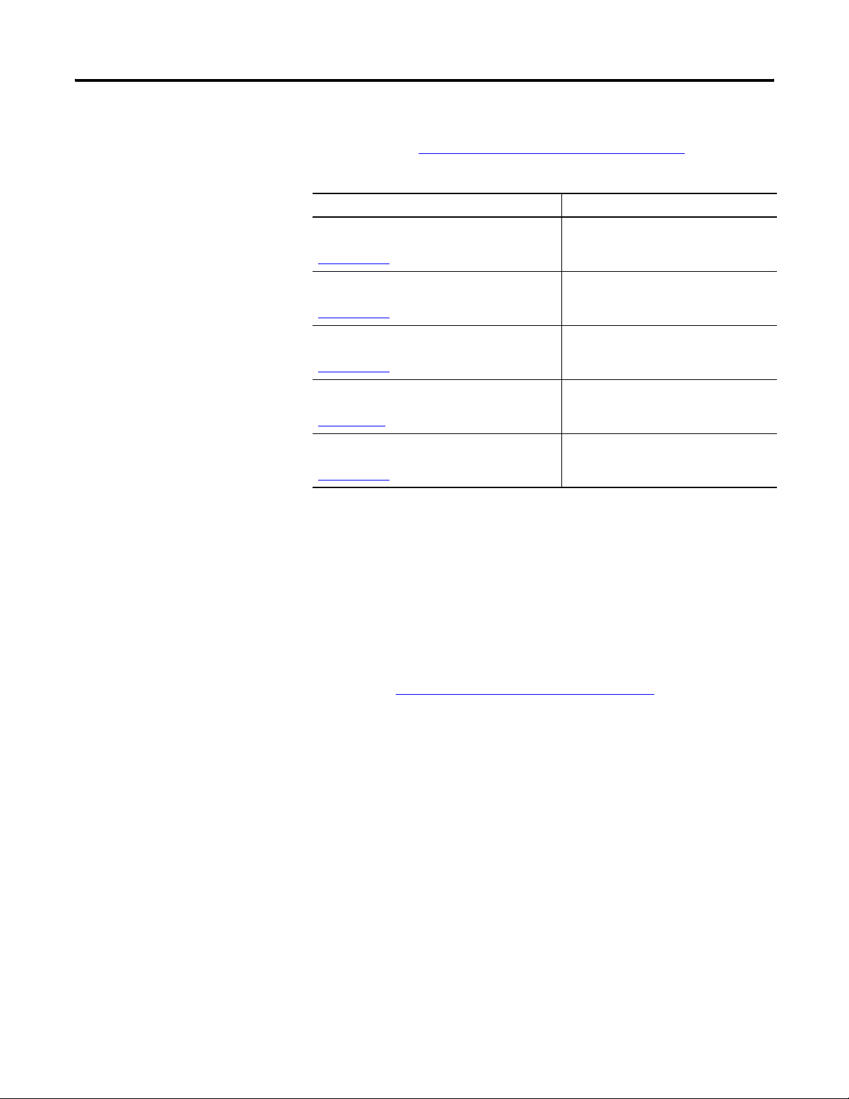
For additional information, refer to these publications, that you can
download from http://literature.rockwellautomation.com
Resource Description
DeviceNet Communications for PanelView Plus
Terminals User Manual, publication
2711P-UM004
ControlNet Communications for PanelView Plus
Terminals User Manual, publication
2711P-UM003
Modbus Applications for PanelView Plus
Terminals User Manual, publication
2711P-UM002
Wiring and Grounding Guidelines for PanelView
Plus Devices Technical Data, publication
2711P-TD001
Software Development Kit for PanelView Plus
CE Terminals User Manual, publication
2711P-UM005
Provides procedures for creating a
DeviceNet application to run on a
PanelView Plus terminal.
Provides procedures for creating a
ControlNet application to run on a
PanelView Plus terminal.
Provides procedures for creating a
Modbus application to run on a
PanelView Plus terminal.
Provides grounding and wiring
guidelines for PanelView Plus terminals.
Provides information for programmers to
develop CE applications for PanelView
Plus CE terminals.
.
You may also want to refer to:
• online help for FactoryTalk View Studio or RSLinx software.
• documentation for your controller.
Software and Firmware Upgrades
To receive software updates (software serial number required) and
firmware upgrades for your terminal:
• call your local Rockwell Automation sales office or distributor.
• access http://support.rockwellautomation.com
10 Publication 2711P-UM001I-EN-P - December 2008
Page 11

Overview
Chapter
1
Chapter Objectives
Software Support
This chapter gives an overview of the PanelView Plus terminals.
• Software support
• PanelView Plus 400 and 600 features
• PanelView Plus 700 to 1500 features
• Catalog number configuration
• Product components
FactoryTalk View ME runtime software is included with all PanelView
Plus and PanelView Plus CE terminals. This software provides runtime
and terminal configuration software for the terminals and does not
require activation.
You use FactoryTalk View Studio software on a personal computer to
create applications that run in the terminals. This software is
purchased separately.
The open Windows CE.NET environment of the PanelView Plus CE
terminals provides:
• familiar Windows desktop and user interface.
• terminal server-client support to configured servers
• Internet Explorer web browser.
• software development kit to support custom C++ applications
for Windows CE.NET operating system.
• third-party device support for Windows CE.NET operating
system.
• Windows CE.NET operating system provides the following
programs:
– File viewers for MS Office: Excel, Word, PowerPoint
– PDF file viewer
– WordPad text editor
– WebServer application
– FTP server
– Support for the .NET compact framework
Some of the above software applications are included on the
PanelView Plus CE Accessory CD.
11Publication 2711P-UM001I-EN-P - December 2008 11
Page 12
Chapter 1 Overview
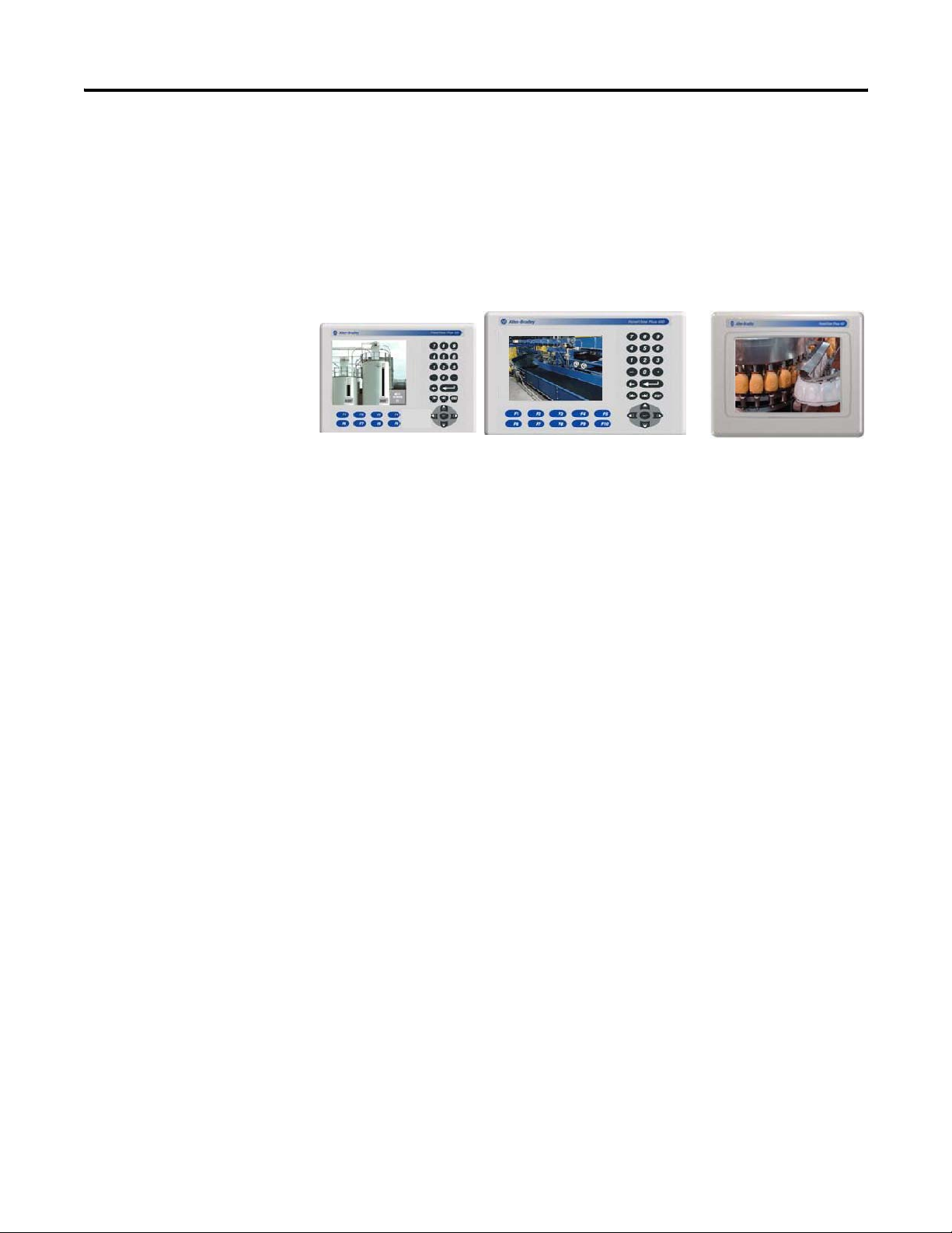
PanelView Plus 400 and 600 Terminals
The PanelView Plus 400 and 600 terminals offer:
• base-configured units.
• communication modules.
• power supply, AC or DC.
• grayscale and color displays.
The PanelView Plus 400 and 600 terminals are HMI devices that
provide these features:
• PanelView Plus 400 terminals
– Color or grayscale graphic displays
– Keypad or keypad and touch screen input support
• PanelView Plus 600 terminals
– Color or grayscale graphic displays
– Keypad, touch screen, or keypad and touch screen input
• Base-configured unit
– RS-232 only
– RS-232, Ethernet, and modular communications interface
• Communication modules provide add-on capability to
base-configured units with a modular communications interface
• Power input, AC (85…264V) or DC (18…30V)
• CompactFlash card slot supports Type 1 CompactFlash cards
• USB port for attaching mouse, keyboard, printer, bar code
scanner, and other devices
• Same panel cutouts as the PanelView Standard 550 terminals
12 Publication 2711P-UM001I-EN-P - December 2008
Page 13
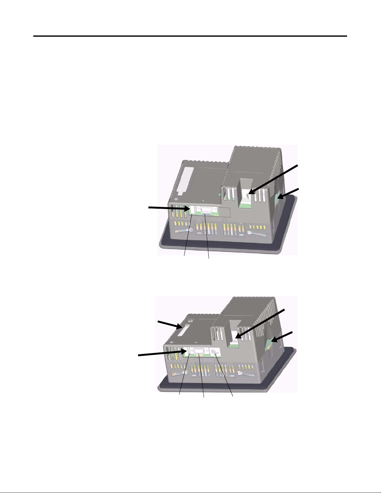
Base-configured Units
The base-configured unit of the 400 and 600 terminals is available in
two versions.
Base Unit with RS-232 Only
Base-configured Unit with RS-232
and USB Port only
Overview Chapter 1
• Base unit with RS-232 port and one USB port
• Base unit with RS-232 port, 10/100BaseT Ethernet port, one USB
port, and a network interface for a communication module
Power Input, AC or DC
CompactFlash Slot
Base Unit with RS-232, Ethernet Port, and Modular Communications Interface
Interface for
Communication Module
Base-configured Unit with
RS-232, USB, Ethernet Port, and Network
Interface for Communication Module.
USB Port
USB Port
RS-232 Port
RS-232 Port
Power Input, AC or DC
CompactFlash Slot
Ethernet Port
Publication 2711P-UM001I-EN-P - December 2008 13
Page 14
Chapter 1 Overview
Communication Modules
You can attach a communication module with a network interface to
the base-configured unit of the PanelView Plus 400 and 600 terminals
to increase your communication capability with these networks:
• DH-485
• DH+
• Remote I/O (single rack)
• Isolated RS-232
• DeviceNet
• ControlNet
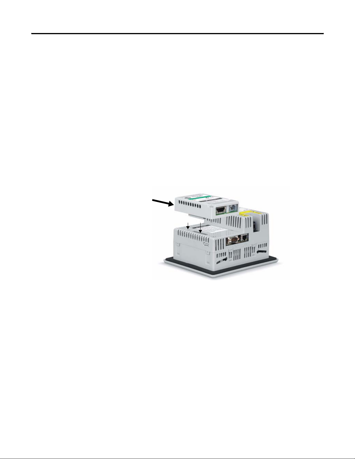
The communication module installs easily on the back of the unit.
Communication
Module
Power Options
The base-configured unit of the PanelView Plus 400 and 600 terminals
is available with either AC (85…264V) or DC (18…30V) power input
providing application flexibility.
14 Publication 2711P-UM001I-EN-P - December 2008
Page 15
Overview Chapter 1
Display and Input Options
PanelView Plus 400 and 600 terminals are available with these display
and operator input options:
• 400 terminals: 3.8 in. grayscale (320 x 240) graphics display with
keypad or 3.5 in. (320 x 240) color with keypad or keypad and
touch support
• 600 terminals: 5.5 in. color or grayscale (320 x 240) graphics
display with keypad, touch screen, or keypad and touch support
Touch Screen
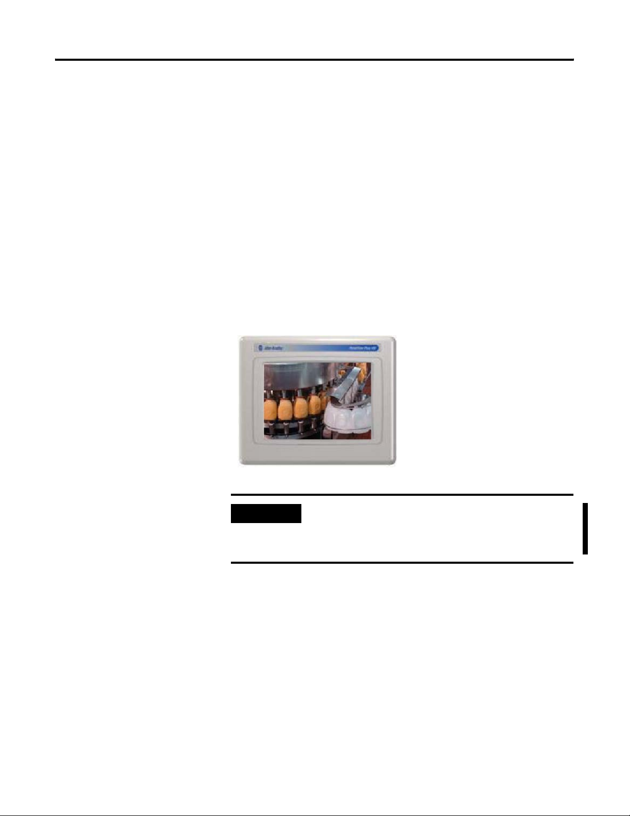
The PanelView Plus 600 terminals offer an analog resistive touch
screen for touch input.
600 Touch Grayscale or Color Terminal
IMPORTANT
The touch screen may be operated with a finger, gloved finger,
or plastic stylus device with a minimum tip radius of
1.3 mm (0.051 in.) to prevent damage to the touch screen. Using
any other object or tool may damage the touch screen.
Publication 2711P-UM001I-EN-P - December 2008 15
Page 16
Chapter 1 Overview
Keypad or Keypad and Touch
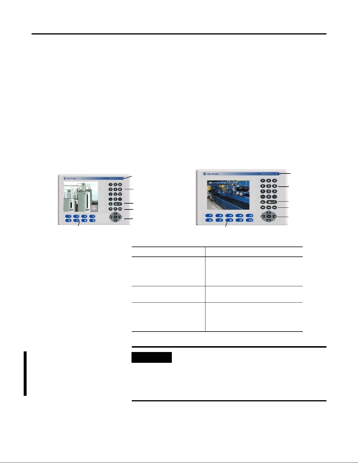
The keypad versions of the PanelView Plus 400 and 600 terminals are
available with these options:
• 400 terminals: grayscale display with keypad or color display
with keypad or keypad and touch input
• 400 and 600 terminals offer an analog resistive touch screen for
touch input.
• 600 terminals: color or grayscale displays with either keypad, or
keypad and touch input
400 Grayscale with Keypad, or 400 Color
with Keypad or Keypad and Touch
8 Programmable Function Keys
600 Grayscale or Color Terminal
with Keypad, or Keypad and Touch Screen
Replaceable ID Label
Numeric Keypad
Backspace and Enter Keys
Tab and Shift Keys
Navigation Keys
10 Relegendable Programmable Function Keys
Replaceable
ID Label
Numeric Keypad
Backspace and
Enter Keys
Tab and Shift Keys
Navigation Keys
Keys Description
400 F1 through F8
600 F1 through F10
Programmable keys that initiate functions
on terminal display. Replaceable legends
are available for the 600 terminals allowing
for custom function key labels.
Numeric Keypad 0…9, ., -, Backspace, Enter, Left and Right
Tab keys, Shift keys
Navigation Keys Use the arrow keys for navigation.
Use the Alt+arrow keys to activate home,
end, page up, and page down functions.
IMPORTANT
The keypad is designed for finger or gloved finger operation.
The touch screen may be operated with a finger, gloved finger,
or plastic touch screen stylus with a minimum tip radius of
1.3 mm (0.051 in.) to prevent damage to the touch screen.
Using any other object or tool may damage the touch screen
or keypad.
16 Publication 2711P-UM001I-EN-P - December 2008
Page 17
Overview Chapter 1
PanelView Plus 700 to 1500 Terminals
This section gives an overview of the PanelView Plus 700, 1000, 1250,
1250H, and 1500 terminals.
• Modular components
• Base-configured unit
• Communication modules
• Logic module, standard or CE
• Power supply, AC or DC
• Display modules
The PanelView Plus 700 to 1500 terminals are HMI devices that offer
these features:
• Graphic color-display modules with keypad, touch screen, or
keypad and touch screen support
• Analog resistive touch screen
• Ethernet and serial communications
• Modular communication interface for easy add-on capability
• Memory expansion modules for field upgrades to 256 MB RAM
and 512 MB CompactFlash
• Power input, AC (85…264V AC) or DC (18…32V DC)
• CompactFlash card slot supports Type 1 CompactFlash cards
• USB ports provide connections for keyboard, mouse, and printer
• Field replaceable bezels
• Same panel cutouts as the PanelView Standard and PanelView
Enhanced terminals
• Standard or CE logic module
Publication 2711P-UM001I-EN-P - December 2008 17
Page 18
Chapter 1 Overview
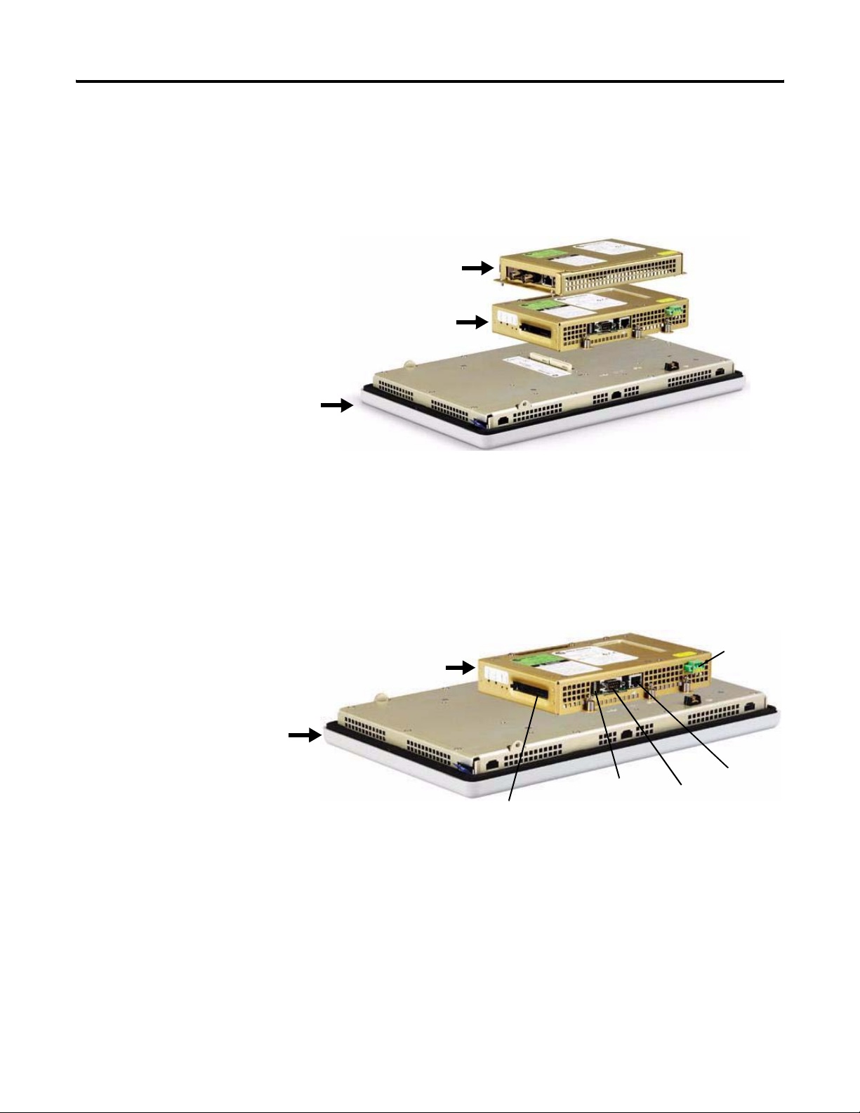
Modular Components
The terminals use modular components allowing for flexible
configuration, installation, and upgrades. You can order items as
separate components or factory assembled per your configuration.
Communication Module
Logic Module
Display Module
Display Module
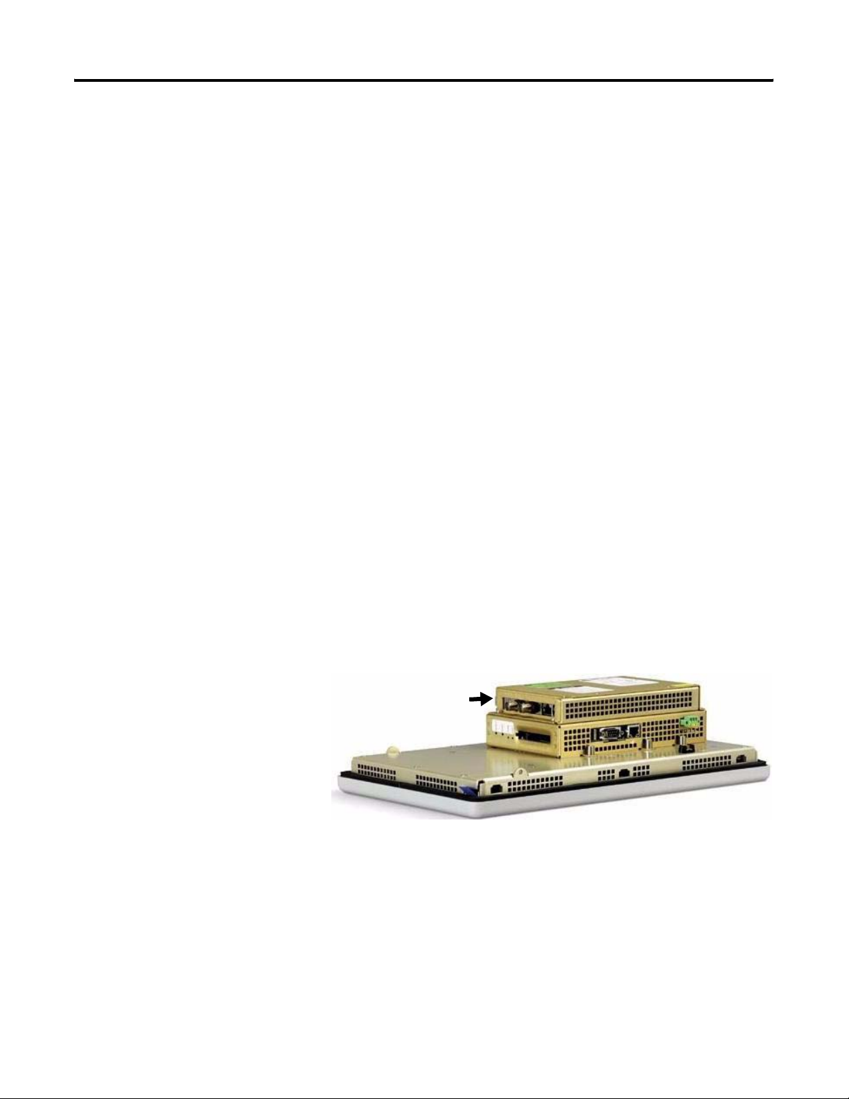
Base-configured Unit
The base-configured unit of the terminal consists of:
• display module (700, 1000, 1250, 1500) with keypad, touch, or
keypad and touch input.
• logic module.
Logic Module
USB Ports
CompactFlash Card Slot
Serial Port
The logic module contains:
• 24V DC input (18…32V) or AC input (85…264V).
• SDRAM and flash memory, various sizes.
• 10/100 BaseT Ethernet port.
• serial RS-232 port for file transfers, printing, and logic controller
communications.
• two USB ports for attaching mouse, keyboard, or printer.
• card slot for Type I CompactFlash cards.
• battery-backed real-time clock.
Ethernet Port
Power Input,
AC or DC
18 Publication 2711P-UM001I-EN-P - December 2008
Page 19
Overview Chapter 1
Logic Modules and CompactFlash
The logic module is available with or without internal CompactFlash.
The contents of the internal CompactFlash is what differentiates a
PanelView Plus device from a PanelView Plus CE device.
• For the PanelView Plus terminals, the internal CompactFlash
contains FactoryTalk View ME software and flash memory.
• For the PanelView Plus CE terminals, the internal CompactFlash
contains the open Windows CE operating system,
FactoryTalk View ME software, and flash memory.
The internal CompactFlash is available in different sizes and can be
ordered separately or bundled with the logic module.
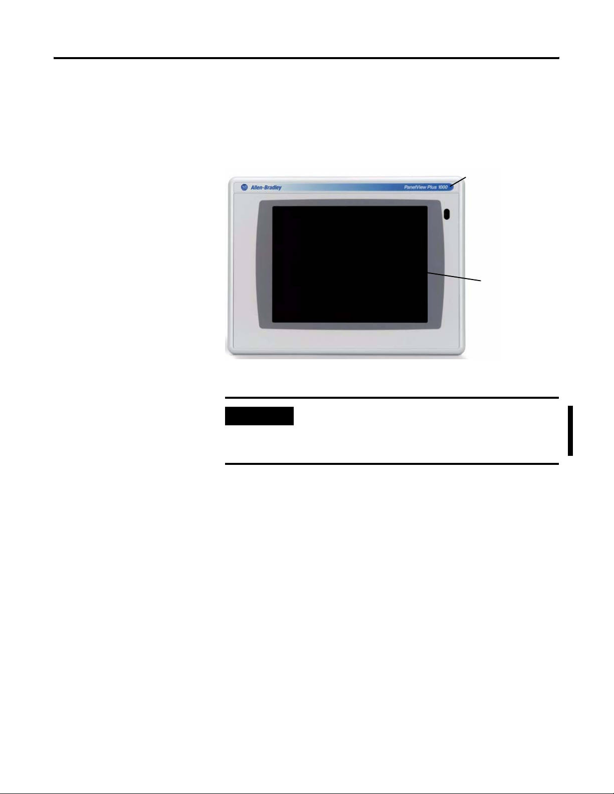
Communication Modules
You can attach a communication module with a network interface to
the base-configured unit of the terminal to increase your
communication capability with these networks:
• DH+/DH-485/Remote I/O
• DeviceNet
• ControlNet
The communication module installs easily on top of the logic module
on the back of the unit.
Communication Module
Publication 2711P-UM001I-EN-P - December 2008 19
Page 20

Chapter 1 Overview
Power Options
The basic configured units of the 700 to 1500 PanelView Plus
terminals provide application flexibility with three available power
power options:
• AC (85...264V)
• unisolated DC (18...32V)
• isolated DC (18...32V)
For DC applications using AC power, a remote AC-to-DC power
supply, cat. no. 2711P-RSACDIN, is available for DIN-rail mounting.
Display Modules
The terminals offer a range of TFT color graphic displays with either
keypad, touch screen, or keypad and touch screen support.
• 700 (6.5 in.)
• 1000 (10.4 in.)
• 1250 (12.1 in.)
• 1500 (15 in.)
The 700 and 1250 touch displays are available in conformal-coated
options. A 1250 high-bright, touch display module is available for
outdoor installations. Plus the 1250 and 1500 touch displays offer an
integral antiglare overlay.
All displays have common features and firmware providing for easy
migration to a larger display. Field-replaceable bezels are also
available.
20 Publication 2711P-UM001I-EN-P - December 2008
Page 21
Overview Chapter 1
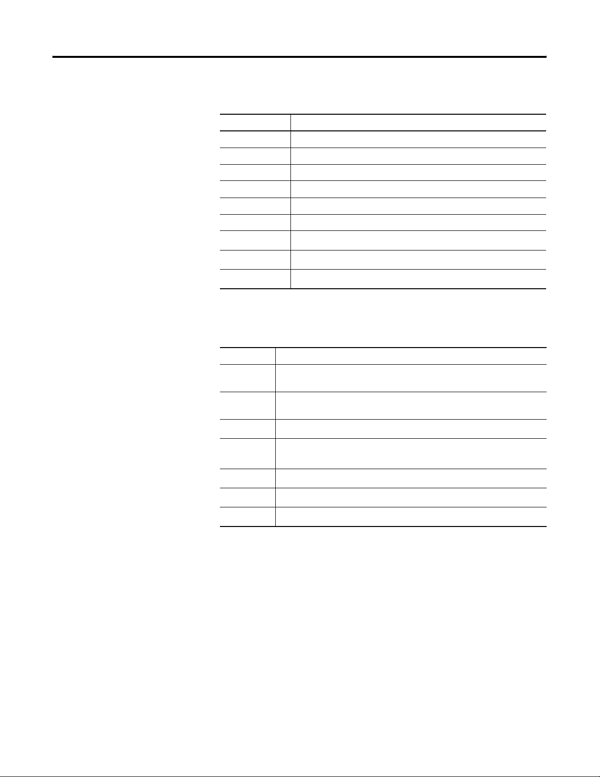
Touch Screen
All touch-screen displays are analog resistive and similar except for
size.
Replaceable ID Label
Touch Screen
IMPORTANT
The touch screen may be operated with a finger, gloved finger,
or plastic stylus device with a minimum tip radius of
1.3 mm (0.051 in.) to prevent damage to the touch screen. Using
any other object or tool may damage the touch screen.
Publication 2711P-UM001I-EN-P - December 2008 21
Page 22

Chapter 1 Overview
Programmable Function Keys
(optional custom legends)
Keypad or Keypad and Touch
All displays are similar except for size and the number of function
keys available.
Allen-Bradley Label
Numeric Keypad
Backspace
and Enter Keys
Tab and Shift Keys
Esc, CT, Alt Keys
Navigation Keys
Programmable Function Keys
(optional custom legends)
IMPORTANT
The keypad is designed for finger or gloved finger operation.
The touch screen may be operated with a finger, gloved finger,
or plastic stylus device with a minimum tip radius of
1.3 mm (0.051 in.) to prevent damage to the touch screen.
Using any other object or tool may damage the touch screen
or keypad.
The Kxx and Fxx function keys on the keypad terminals are
programmable.
Function Keys Description
Function Keys
700 (F1 through F10, K1 through K12)
1000 (F1 through F16, K1 through K16)
1250 (F1 through F20, K1 through K20)
1500 (F1 through F20, K1 through K20)
Numeric Keypad 0…9, ., -, Backspace, Enter, Left and Right
Programmable keys that initiate functions
on terminal display. Replaceable legends
are available for the terminals allowing for
custom function key labels.
tab, Shift, Esc, Ctrl, Alt keys.
Navigation Keys Use the arrow keys to move cursor in lists
and select objects.
Alt+arrow key activates home, end, page
up, page down functions.
22 Publication 2711P-UM001I-EN-P - December 2008
Page 23

Overview Chapter 1
Catalog Number
The table shows the catalog number configuration for configured
versions of the PanelView Plus and PanelView Plus CE terminals. Not
Configuration
Input
Ty pe
||| | | |
2711P- K = Keypad 4 = 3.5 in. C = Color PanelView Plus 400 and 600 Terminals A = AC 1= Logic Module 64 MB K = Conformal-Coated
T = Touch 6 = 5.5 in. M=Grayscale 1 = Remote I/O (single rack), Ethernet,
B = Keypad/Touch 7 = 6.5 in. 3 = DH-485, Ethernet, RS-232 & USB 3 = Logic Module with 256 MB
(1)
Additional communication options are available and can be seen in the following section.
(2)
Applies to PanelView Plus 700 to 1500 terminals only.
Display
Size
10 = 10.4 in. 5 = RS-232 & USB 6 = CE Logic Module with 128 MB
12 = 12.1 in. 8 = DH+, Ethernet, RS-232 & USB 7 = CE Logic Module with 256 MB
15 = 15 in. 20 = Ehernet, RS-232 & USB plus
Display Type
all combinations of options are available for sale.
Communication
RS-232 & USB
Communication Module Interface
PanelView Plus 700 to 1500 Terminals
4 = Ethernet, RS-232 & (2) USB
6 = DH+, DH-485, RIO, Ethernet, RS-232 & (2) USB
15 = ControlNet, Ethernet, RS-232 & (2) USB
(1)
Power Logic Module with
Flash and RAM Memory
D = DC 2 = Logic Module 128 MB
Special Option
(2)
(2)
PanelView Plus Product Components
Components are available as separate catalog numbers for field
installation or replacement.
Display Modules (700 to 1500 only)
Cat. No. Description
2711P-RDK7C 700 keypad color display
2711P-RDT7C 700 touch color display
2711P-RDT7CM 700 touch color display, marine certified
2711P-RDB7C 700 keypad and touch color display
2711P-RDB7CM 700 keypad and touch color display, marine certified
2711P-RDT7CK Conformal-coated 700 touch color display
2711P-RDK10C 1000 keypad color display
2711P-RDT10C 1000 touch color display
2711P-RDT10CM 1000 touch display, marine certified
2711P-RDB10C 1000 keypad and touch color display
2711P-RDB10CM 1000 keypad and touch display, marine certified
2711P-RDK12C 1250 keypad color display
2711P-RDT12C 1250 touch color display
2711P-RDT12AG 1250 touch color display with antiglare overlay
Publication 2711P-UM001I-EN-P - December 2008 23
Page 24

Chapter 1 Overview
Display Modules (700 to 1500 only)
Cat. No. Description
2711P-RDT12CK Conformal-coated 1250 touch color display
2711P-RDT12H 1250 high-bright touch color display
2711P-RDB12C 1250 keypad and touch color display
2711P-RDK15C 1500 keypad color display
2711P-RDT15C 1500 touch color display
2711P-RDT15AG 1500 touch color display with antiglare overlay
2711P-RDB15C 1500 keypad and touch color display
Logic Modules (700 to 1500 only)
Cat. No. Description
Standard Logic Modules for PanelView Plus Terminals
2711P-RP Logic module without flash/RAM memory, DC input
2711P-RPD Logic module, without memory, isolated DC input, marine
certified
2711P-RPA Logic module without flash/RAM memory, AC input, marine
certified
2711P-RP1 Logic module with 64 MB flash/64 MB RAM, DC input
2711P-RP1A Logic module with 64 MB flash/64 MB RAM, AC input, marine
certified
2711P-RP1D Logic module with 64MB, isolated DC input, marine certified
2711P-RP2 Logic module with 128 MB flash/128 MB RAM, DC input
2711P-RP2A Logic module with 128 MB flash/128 MB RAM, AC input, marine
certified
2711P-RP2D Logic module with 128MB, isolated DC input, marine certified
2711P-RP2DK Conformal-coated logic module with 128MB, isolated DC input
2711P-RP2K Conformal-coated logic module with 128 MB flash/128 MB RAM,
DC input
2711P-RP3 Logic module with 256 MB flash/256 MB RAM, DC input
2711P-RP3A Logic module with 256 MB flash/256 MB RAM, AC input, marine
certified
2711P-RP3D Logic module with 256MB, isolated DC input, marine certified
CE Logic Modules for PanelView Plus CE Terminals
2711P-RP6 CE logic module with 128 MB flash/128 MB RAM, DC input
2711P-RP6A CE logic module with 128 MB flash/128 MB RAM, AC input,
marine certified
2711P-RP6D CE logic module with 128MB, isolated DC input, marine certified
2711P-RP6DK CE conformal-coated logic module with 128MB, isolated DC input
2711P-RP6K CE conformal-coated logic module with 128 MB flash/128 MB
RAM, DC input
24 Publication 2711P-UM001I-EN-P - December 2008
Page 25

Overview Chapter 1
Logic Modules (700 to 1500 only)
Cat. No. Description
2711P-RP7 CE logic module with 256 MB flash/256 MB RAM, DC input
2711P-RP7A CE logic module with 256 MB flash/256 MB RAM, AC input,
marine certified
2711P-RP7D CE logic module with 256 MB, isolated DC input, marine certified
Communication Modules
Terminal Type Cat. No. Description
2711P-RN1 Single-rack remote I/O communication module
2711P-RN3 DH-485 communication module
2711P-RN8 DH+ communication module
400 and 600
2711P-RN10C DeviceNet communication module
2711P-RN15C ControlNet communication module
2711P-RN22C RS-232 isolated communication module
2711P-RN6 DH+/DH-485/remote I/O communication module
2711P-RN6K Conformal-coated DH+/DH-485/remote I/O
communication module
2711P-RN10H DeviceNet communication module
700 to 1500
2711P-RN10HK Conformal-coated DeviceNet communication
module
2711P-RN15S ControlNet communication module, marine
certified
2711P-RN15SK Conformal-coated ControlNet communication
module
Internal Compact Flash
Cat. No. Description
Internal CompactFlash for Standard Logic Modules
2711P-RW1 64 MB CompactFlash with FactoryTalk View ME software
2711P-RW2 128 MB CompactFlash with FactoryTalk View ME software
2711P-RW3 256 MB CompactFlash with FactoryTalk View ME software
Internal CompactFlash for CE Logic Modules
2711P-RW6 128 MB CompactFlash with FactoryTalk View ME software and the
open Windows CE operating system for the CE logic module
2711P-RW7 256 MB CompactFlash with FactoryTalk View ME software and the
open Windows CE operating system for the CE logic module
2711P-RW8 512 MB CompactFlash with FactoryTalk View ME software and the
open Windows CE operating system for the CE logic module
Publication 2711P-UM001I-EN-P - December 2008 25
Page 26

Chapter 1 Overview
RAM Memory (700 to 1500 only)
Cat. No. Description
2711P-RR64 64 MB SODIMM memory
2711P-RR128 128 MB SODIMM memory
2711P-RR256 256 MB SODIMM memory
Compact Flash Cards (Blank)
Cat. No. Description
2711P-RC2 128 MB blank CompactFlash card
2711P-RC3 256 MB blank CompactFlash card
2711P-RC4 512 MB blank CompactFlash card
2711P-RCH CompactFlash to PCMCIA adapter
Legend Kits
Cat. No. Description
2711P-RFK6 Replacement legends strips for 600 keypad terminal
2711P-RFK7 Replacement legends strips for 700 keypad terminal
2711P-RFK10 Replacement legends strips for 1000 keypad terminal
2711P-RFK12 Replacement legends strips for 1250 keypad terminal
2711P-RFK15 Replacement legends strips for 1500 keypad terminal
Backlights (700 to 1500 only)
Cat. No. Description
2711P-RL7C Replacement color backlight for 700 series A and B display modules
2711P-RL7C2 Replacement color backlight for 700 series C and D display modules
2711P-RL10C Replacement color backlight for 1000 series A display modules
2711P-RL10C2 Replacement color backlight for 1000 series B display modules
2711P-RL12C Replacement color backlight for 1250 series A and B display modules
2711P-RL12C2 Replacement color backlight for 1250 series C display modules
2711P-RL15C Replacement color backlight for 1500 series B display modules
Replacement Bezels
Cat. No. Description
2711P-RBK7 Replacement bezel for 700 keypad terminal
2711P-RBT7 Replacement bezel for 700 touch terminal
2711P-RBB7 Replacement bezel for 700 keypad or keypad/touch terminal
2711P-RBK10 Replacement bezel for 1000 keypad terminal
2711P-RBT10 Replacement bezel for 1000 touch terminal
2711P-RBB10 Replacement bezel for 1000 keypad or keypad/touch terminal
26 Publication 2711P-UM001I-EN-P - December 2008
Page 27

Overview Chapter 1
Replacement Bezels
Cat. No. Description
2711P-RBK12 Replacement bezel for 1250 keypad terminal
2711P-RBT12 Replacement bezel for 1250 touch terminal
2711P-RBT12H Replacement bezel for 1250 high-bright touch terminal
2711P-RBB12 Replacement bezel for 1250 keypad or keypad/touch terminal
2711P-RBK15 Replacement bezel for 1500 keypad terminal
2711P-RBT15 Replacement bezel for 1500 touch terminal
2711P-RBB15 Replacement bezel for 1500 keypad or keypad/touch terminal
Protective Antiglare Overlays
Cat. No.
(1)
Description
2711P-RGK4 Antiglare overlay for PanelView Plus 400 grayscale terminal
2711P-RGB4 Antiglare overlay for PanelView Plus 400 color keypad/touch terminal
2711P-RGK6 Antiglare overlay for PanelView Plus 600 keypad or keypad/touch
terminal
2711P-RGT6 Antiglare overlay for PanelView Plus 600 touch terminal
2711P-RGK7 Antiglare overlay for PanelView Plus 700 keypad or keypad/touch
terminal
2711P-RGT7 Antiglare overlay for PanelView Plus 700 touch terminal
2711P-RGK10 Antiglare overlay for PanelView Plus 1000 keypad or keypad/touch
terminal
2711P-RGT10 Antiglare overlay for PanelView Plus 1000 touch terminal
2711-RGK12 Antiglare overlay for PanelView Plus 1250 keypad or keypad/touch
terminal
2711P-RGT12 Antiglare overlay for PanelView Plus 1250 touch and high-bright touch
terminal
2711P-RGK15 Antiglare overlay for PanelView Plus 1500 keypad or keypad/touch
terminal
2711P-RGT15 Antiglare overlay for PanelView Plus 1500 touch terminal
(1)
All catalog numbers ship with a quantity of three overlays.
Adapter Plates
Cat. No. Description
2711P-RAK4 Adapts a PanelView Plus 400 keypad terminal to a PanelView
Standard 550 keypad cutout
2711P-RAK6 Adapts a PanelView Plus 600 keypad terminal to a PanelView
Standard 600 keypad cutout
2711P-RAK7 Adapts a PanelView Plus 700 keypad terminal to a PanelView
Standard 900 keypad cutout
2711P-RAT7 Adapts a PanelView Plus 700 touch terminal to a PanelView Standard
900 touch cutout
2711P-RAK10 Adapts a PanelView Plus 1000 keypad terminal to a PanelView
1000/1000E keypad cutout
Publication 2711P-UM001I-EN-P - December 2008 27
Page 28

Chapter 1 Overview
Adapter Plates
Cat. No. Description
2711P-RAT10 Adapts a PanelView Plus 1000 touch terminal to a PanelView
1000/1000E touch cutout
2711P-RAK12E Adapts a PanelView Plus 1250 (or PV1000/1000E) keypad terminal to a
PanelView 1200/1400E keypad cutout
2711P-RAT12E2 Adapts a PanelView Plus 1250 (or PV1000/1000E) touch terminal to a
PanelView 1200E touch cutout
2711P-RAT12E Adapts a PanelView Plus 1250 (or PV1000/1000E) touch terminal to a
PanelView 1400E touch cutout
2711P-RAK12S Adapts a PanelView Plus 1250 (or PV1000/1000E) keypad terminal to a
PanelView Standard 1400 keypad cutout
2711P-RAT12S Adapts a PanelView Plus 1250 (or PV1000/1000E) touch terminal to a
PanelView Standard 1400 touch cutout
2711P-RAK15 Adapts a PanelView Plus 1500 keypad or keypad/touch terminal to a
PanelView 1200E/1400E keypad terminal
2711P-RAT15 Adapts a PanelView Plus 1500 touch terminal to a PanelView 1400E
touch cutout
Cables
Cat. No. Description
2711-NC13 RS-232 operating/programming cable (9-pin D-shell to 9-pin D-shell),
5 m (16.4 ft)
2711-NC14 RS-232 operating/programming cable (9-pin D-shell to 9-pin D-shell),
10 m (32.7 ft)
2711-NC17 Remote RS-232 serial cable (9-pin D-shell to 9-pin D-shell)
2711-NC21 RS-232 operating cable (9-pin D-shell to 8-pin mini DIN), 5 m (16.4 ft)
2711-NC22 RS-232 operating cable (9-pin D-shell to 8-pin mini DIN), 10 m (32.7 ft)
1761-CBL-AS03 DH-485 operating cable (6-pin Phoenix to RJ45), 3 m (10 ft)
1761-CBL-AS09 DH-485 operating cable (6-pin Phoenix to RJ45), 9 m (30 ft)
1746-C10 DH-485 network interface cable (SDL AMP to RJ45), 1.83 m (6 ft)
1746-C11 DH-485 network interface cable (SDL AMP to RJ45), .3 m (1 ft.)
1784-CP14 DH-485 network interface cable (5-pin Phoenix to RJ45)
2711P-CBL-EX04 Ethernet CAT5 crossover cable, industrial grade, 4.3 m (14 ft)
Communication Adapters
Cat. No. Description
1761-NET-AIC AIC+ advanced interface converter
1747-AIC DH-485 isolated link coupler for use with DH-485 communication
modules (2711P-RN3, 2711P-RN6)
Remote AC Power Supply (700 to 1500 only)
Cat. No. Description
2711P-RSACDIN DIN-rail power supply, AC-to-DC, 85…265V AC, 47…63 Hz
28 Publication 2711P-UM001I-EN-P - December 2008
Page 29
Overview Chapter 1
Miscellaneous
Cat. No. Description
2711P-RVT12 Solar visor for outdoor high-bright 1250 touch screen display modules
2711P-RY2032 Replacement battery for 700 to 1500 terminals
2711P-RTMC Replacement mounting clips for 700 to 1500 terminals, quantity of 8
2711P-RTFC Replacement mounting levers for 400 and 600 terminals, quantity of 8
2711P-RVAC Replacement AC power terminal block for 400 and 600 terminals
2711-TBDC Replacement DC power terminal block for 400 and 600 terminals
(1)
2711P-RTBDC3
2711P-RTBDC2
2711P-RTBAC3
(1)
Catalog numbers ship with a quantity of ten.
Three-position terminal block for DC logic modules, series A to D
(1)
Two-position terminal block for DC logic modules, series E or later
(1)
Three-position terminal block for all AC logic modules
Firmware Upgrade Kits
Cat. No. Description
2711P-RU310 PanelView Plus media kit includes firmware upgrade wizard, one firmware
license, certificate of authenticity, end user license agreement.
2711P-RUA310PanelView Plus advanced media kit includes the 2711P-RU310 media kit,
PCMCIA to compact flash adapter, and 32 MB CompactFlash card.
2711P-RUL01
Firmware upgrade license kit with one PanelView Plus firmware license.
2711P-RUL05 Firmware upgrade license kit with five PanelView Plus firmware
licenses.
2711P-RUL10
2711P-RUL25
2711P-RUL50
(1)
Also includes certificate of authenticity, end user license agreement, installation instructions.
Firmware upgrade license kit with 10 PanelView Plus firmware licenses.
Firmware upgrade license kit with 25 PanelView Plus firmware licenses.
Firmware upgrade license kit with 50 PanelView Plus firmware licenses.
(1)
(1)
(1)
(1)
(1)
Publication 2711P-UM001I-EN-P - December 2008 29
Page 30

Chapter 1 Overview
30 Publication 2711P-UM001I-EN-P - December 2008
Page 31

Installation
Chapter
2
Chapter Objectives
Hazardous Locations
This chapter provides pre-installation information and procedures on
how to install the terminals.
• Hazardous locations
• Environment and enclosure
• Outdoor installation for 1250 high-bright display module
• Required tools
• Clearances
• Panel cutout dimensions
• Mount the 400 or 600 terminal in a panel
• Mount the 700 to 1500 terminals in a panel
• Product dimensions
This equipment is suitable for these locations:
• Class I, Division 2, Groups A, B, C, D.
• Class I, Zone 2, Group IIC.
• Class II, Division 2, Groups F, G.
• Class III.
• ordinary, nonhazardous locations.
The following statement applies to use in hazardous locations.
WARNING
31Publication 2711P-UM001I-EN-P - December 2008 31
Explosion Hazard
Substitution of components may impair suitability for hazardous
locations.
Do not disconnect equipment unless power has been switched
off and area is known to be nonhazardous.
Do not connect or disconnect components unless power has
been switched off.
All wiring must comply with N.E.C. articles 501, 502, 503,
and/or C.E.C. section 18-1J2 as appropriate.
Peripheral equipment must be suitable for the location in which
it is used.
Page 32

Chapter 2 Installation
The terminals have a temperature code of T4 when operating in a 55
°C (131 °F) maximum ambient temperature. Do not install the
terminals in environments where atmospheric gases have ignition
temperatures less than 135 °C (275 °F).
USB Ports
The terminals contain universal serial bus (USB) ports that comply
with hazardous location environments. This section details the
field-wiring compliance requirements and is provided in accordance
with the National Electrical Code, article 500.
PanelView Plus 400, 600, and 700 to 1500 Terminals Control Drawing
Associated Nonincendive Field Wiring Apparatus
PanelView Plus 400, 600, and 700 to 1500 Host Product
Nonincendive Field
Wiring Apparatus
Nonincendive Field Wiring
USB Port
USB
Peripheral
Device
Table 1 - PanelView Plus 400, 600, and 700 to 1500 USB Port Circuit Parameters
Display Size
400 and 600
C
a
V
oc
I
sc
Groups
A and B
Groups
C and D
Groups
A and B
5.25V DC 1.68 A 10 µF 10 µF 15 µH 15 µH
L
a
Groups
C and D
Series A and B
400 and 600
5.25V DC 1.68 A 10 µF 10 µF 3.5 µH 15 µH
Series C or later
700 to 1500 5.25V DC 1.68 A 10 µF 10 µF 15 µH 15 µH
Selected nonincendive field wiring apparatus must have nonincendive
circuit parameters conforming with Table 2.
Table 2 - Required Circuit Parameters for the USB Peripheral Device
V
max
I
max
Ci + C
+ L
L
i
cable
cable
≥ V
≥ I
£ Ca
£ L
oc
sc
a
32 Publication 2711P-UM001I-EN-P - December 2008
Page 33

Installation Chapter 2
Application Information
Per the National Electrical Code the circuit parameters of
nonincendive field wiring apparatus for use in hazardous locations
shall be coordinated with the associated nonincendive field wiring
apparatus such that their combination remains nonincendive. The
PanelView Plus terminal and the USB peripheral device shall be
treated in this manner.
The circuit parameters of the PanelView Plus terminal USB port are
given in Table 1. The USB peripheral device and its associated cabling
shall have circuit parameters with the limits given in Table 2 for them
to remain nonincendive when used with the PanelView Plus terminal
USB port. If cable capacitance and inductance are not known the
following values from ANSI/ISA-RP 12.06.01-2003 may be used:
C
= 60 pF/ft
cable
L
= 0.20 µH/ft
cable
Nonincendive field wiring must be wired and separated in accordance
with 501.10(B)(3) of the National Electrical Code (NEC) ANSI/NFPA 70
or other local codes as applicable.
This associated nonincendive field wiring apparatus has not been
evaluated for use in combination with another associated
nonincendive field wiring apparatus.
Symbol Definitions
V
I
V
I
C
C
L
L
oc
sc
max
max
i
a
i
a
Open circuit voltge of the host USB port.
Maximum output current of the host USB port.
Maximum applied voltage rating of the USB peripheral device.
shall be greater than or equal to Voc in Table 1. (V
V
max
max
≥ V
oc ).
Maximum current to which the USB peripheral device can be subjected.
I
shall be greater than or equal to Isc in Table 1. (I
max
max
≥ Isc).
Maximum internal capacitance of the USB peripheral device.
Maximum allowed capacitance of the USB peripheral device and its
associated cable. The sum of C
the associated cable shall be less than or equal to C
of the USB peripheral device and C
i
. (Ci + C
a
cable
cable
≤ Ca).
Maximum internal inductance of the USB peripheral device.
Maximum allowed inductance of the USB peripheral device and its
associated cable. The sum of L
the associated cable shall be less than or equal to L
of the USB peripheral device and L
i
. (Li + L
a
cable
cable
≤ La).
of
of
Publication 2711P-UM001I-EN-P - December 2008 33
Page 34

Chapter 2 Installation
Environment and Enclosure
ATTENTION
This equipment is intended for use in a Pollution Degree 2
industrial environment, in overvoltage Category II applications
(as defined in IEC publication 60664-1), at altitudes up to
2000 m (6561 ft) without derating.
The terminals are intended for use with programmable logic
controllers. Terminals that are AC powered must also be
connected to the secondary of an isolating transformer.
This equipment is considered Group 1, Class A industrial
equipment according to IEC/CISPR Publication 11. Without
appropriate precautions, there may be potential difficulties
ensuring electromagnetic compatibility in other environments
due to conducted as well as radiated disturbance.
This equipment is supplied as open-type equipment. It must be
mounted within an enclosure that is suitably designed for those
specific environmental conditions that will be present and
appropriately designed to prevent personal injury resulting from
accessibility to live parts. The interior of the enclosure must be
accessible only by the use of a tool. The terminals meet
specified NEMA Type and IEC ratings only when mounted in a
panel or enclosure with the equivalent rating. Subsequent
sections of this publication may contain additional information
regarding specific enclosure type ratings that are required to
comply with certain product safety certifications.
Outdoor Installation for High-bright Displays
In addition to this publication, see:
• Industrial Automation Wiring and Grounding Guidelines,
publication 1770-4.1
• NEMA Standards publication 250 and IEC publication 60529, as
applicable, for explanations of the degrees of protection provided
by different types of enclosure.
For more enclosure and certification information, refer to the
PanelView Plus/PanelView Plus CE Outdoor High-bright Display
Modules Installation Instructions, publication 2711P-IN026.
When using the high-bright display module, cat. no. 2711P-RDT12H,
outdoors, considerations in maximizing the field life of the front bezel
and display are:
• selecting the proper enclosure.
• orientation of the terminal.
, for additional installation requirements.
34 Publication 2711P-UM001I-EN-P - December 2008
Page 35

Installation Chapter 2
Both ultraviolet and infrared radiation can reduce the field life of any
electronic device. While the materials used in the terminal bezels
provide long field life, that life can be extended by proper installation.
Ultraviolet radiation from the sun causes all plastics to fade or yellow
and become brittle over time. Using an antiglare overlay, cat. no.
2711P-RGT12, will protect the front of the terminal from direct
exposure to UV radiation and greatly increase its field life.
When installing the high-bright display module in an environment
where the front of the terminal will be in direct sunlight during the
hottest part of the day and the external ambient temperature can
exceed 40 °C (104 °F), use the visor kit, cat. no. 2711P-RVT12. The
visor reduces the solar load on the front of the display and helps to
maintain internal temperatures within specification.
The high-bright display module has a built-in temperature sensor that
automatically reduces the backlight intensity if the temperature inside
the cabinet exceeds 55 °C (131 °F). This reduces the risk of damage to
the display.
The paint color, size, and power dissipated by the internal
components of an enclosure affect the temperature rise inside the
cabinet. Hoffman, a Rockwell Automation Encompass Partner, has
information to assist you with enclosure selection and heating/cooling
accessories to meet the temperature requirements of the installed
equipment. See website http://www.hoffmanonline.com
.
Stirring fans or active cooling may be required in high altitude and
high ambient temperature locations to keep the internal enclosure
temperature below 55 °C (131 °F). Use a heater in installations where
the ambient temperature is below 0 °C (32 °F).
The backlight of the high-bright display generates a significant amount
of heat when set to full intensity. To minimize the amount of heat
generated and extend the life of the backlight, decrease the display
intensity by using the screen saver with a 5…10 minute delay.
Avoid placing the terminal on the south (north in the southern
hemisphere) or west side of the cabinet, if possible. This will reduce
the heat rise due to solar loading during the hottest part of the day.
Mount the terminal vertically to minimize solar loading on the display.
Do not mount the terminal in a sloped enclosure if it will be exposed
to direct sunlight.
Publication 2711P-UM001I-EN-P - December 2008 35
Page 36

Chapter 2 Installation
Required Tools
Clearances
These tools are required for panel installation:
• Panel cutout tools
• Small, slotted screwdriver
• Torque wrench (lb•in) for tightening the mounting clips on the
PanelView Plus 700 to 1500 and PanelView Plus CE terminals
Allow adequate clearance around the terminal, inside the enclosure,
for adequate ventilation. Consider heat produced by other devices in
the enclosure. The ambient temperature around the terminals must be
between 0…55 °C (32…131 ºF).
Clearance Area 400 and 600 Terminals 700 to 1500 Terminals
Top 51 mm (2 in.) 51 mm (2 in.)
Bottom 102 mm (4 in.) 51 mm (2 in.)
(1)
Side
Back None 25 mm (1 in.)
(1)
Minimum side clearance for insertion of memory card and cable wiring is 102 mm (4 in.).
25 mm (1 in.) 25 mm (1 in.)
Cutout Dimensions
Use the full size template shipped with your terminal to mark the
cutout dimensions.
Terminal Type Height mm (in.) Width mm (in.)
PanelView Plus 400 and 600 Terminals
400 Keypad or Keypad and Touch 123 (4.86) 156 (6.15)
600 Keypad or Keypad and Touch 142 (5.61) 241 (9.50)
600 Touch 123 (4.86) 156 (6.15)
PanelView Plus and PanelView Plus CE 700 to 1500 Terminals
700 Keypad or Keypad and Touch 167 (6.57) 264 (10.39)
700 Touch 154 (6.08) 220 (8.67)
1000 Keypad or Keypad and Touch 224 (8.8) 375 (14.75)
1000 Touch 224 (8.8) 305 (12.00)
1250 Keypad or Keypad and Touch 257 (10.11) 390 (15.35)
1250 Touch and 1250 High-bright Touch 257 (10.11) 338 (13.29)
1500 Keypad or Keypad and Touch 305 (12.00) 419 (16.50)
1500 Touch 305 (12.00) 391 (15.40)
36 Publication 2711P-UM001I-EN-P - December 2008
Page 37

Installation Chapter 2
Mount the 400 or 600 Terminal in a Panel
Mounting levers secure the terminal to the panel. The number of
levers you use (4 or 6) varies by terminal type.
ATTENTION
Follow these steps to mount the 400 or 600 terminals in a panel.
1. Cut an opening in the panel by using the panel cutout shipped
with the terminal.
2. If a communication module is ordered separately, attach the
module to the base unit before panel installation.
Refer to the instructions shipped with module.
Disconnect all electrical power from the panel before making
the panel cutout.
Make sure the area around the panel cutout is clear.
Take precautions so metal cuttings do not enter any
components already installed in the panel.
Failure to follow these warnings may result in personal injury or
damage to panel components.
3. Make sure the terminal sealing gasket is properly positioned on
the terminal.
This gasket forms a compression-type seal. Do not use sealing
compounds.
Sealing Gasket
4. Install legend strips before installing the terminal if you are
using keypad legend strips on a 600 keypad terminal.
Be careful not to pinch legend strip during installation.
5. Place the terminal in the panel cutout.
If installing the terminal in an existing 550 panel cutout, align
the terminal with the center of the cutout for best gasket sealing.
Publication 2711P-UM001I-EN-P - December 2008 37
Page 38

Chapter 2 Installation
6. Insert all mounting levers into the mounting slots on the
terminal.
Slide each lever until the flat side of the lever touches the
surface of the panel.
Mounting Slots
7. When all levers are in place, slide each lever an additional notch
8. Rotate each lever in the direction indicated until it is in the final
Flat Side of Lever
Mounting Levers
or two until you hear a click.
latch position.
Follow the latching sequence for the optimum terminal fit.
14
4 Levers
Notch
Rotate lever until notch in
lever aligns with proper
alignment mark on terminal.
61
Alignment Marks
3
513
6 Levers
246
2
Use this table as a guide to provide an adequate gasket seal
between the terminal and the panel.
Lever Position Panel Thickness Range Typical Gauge
1 1.5…2.01 mm (0.060…0.079 in.) 16
1
2
3
4
5
6
2 2.03…2.64 mm (0.08…0.104 in.) 14
3 2.67…3.15 mm (0.105…0.124 in.) 12
Terminal
Markings
4 3.17…3.66 mm (0.125…0.144 in.) 10
5 3.68…4.16 mm (0.145…0.164 in.) 8/9
6 4.19…4.75 mm (0.165…0.187 in.) 7
ATTENTION
Follow instructions to provide a proper seal and to
prevent potential damage to the product. Rockwell
Automation assumes no responsibility for water or
chemical damage to the terminal or other equipment
within the enclosure because of improper installation.
38 Publication 2711P-UM001I-EN-P - December 2008
Page 39

Installation Chapter 2
Mount the 700 to 1500 Terminal in a Panel
Mounting clips secure the terminal to the panel. The number of clips
you use (4, 6, or 8) varies by terminal type.
ATTENTION
Follow these steps to mount a 700 to 1500 terminal in a panel.
1. Cut an opening in the panel by using the panel cutout shipped
with the terminal.
2. Make sure the terminal sealing gasket is properly positioned on
the terminal.
This gasket forms a compression-type seal. Do not use sealing
compounds.
Disconnect all electrical power from the panel before making
the panel cutout.
Make sure the area around the panel cutout is clear.
Take precautions so metal cuttings do not enter any
components already installed in the panel.
Failure to follow these warnings may result in personal injury or
damage to panel components.
Sealing Gasket
3. Install the legend strips before installing the terminal if you are
using keypad legend strips on keypad terminals.
Be careful not to pinch the legend strip during installation.
4. Place the terminal in the panel cutout.
Publication 2711P-UM001I-EN-P - December 2008 39
Page 40

Chapter 2 Installation
5. Slide the ends of the mounting clips into the slots on the
terminal.
Mounting Clip
Mounting Clip Slot
6. Tighten the mounting clip screws by hand until the gasket seal
contacts the mounting surface uniformly.
7. Tighten the mounting clips screws to a torque of 0.90…1.1 Nm
(8…10 lb•in) by using the specified sequence, making sure not
to overtighten.
14
Torque Sequence
for 4 Clips
3
ATTENTION
2
Tighten the mounting clips to the specified torque to
513
Torque Sequence
for 6 Clips
246
1
3
Torque Sequence
for 8 Clips
7
5
6
8
4
2
provide a proper seal and to prevent damage to the
product. Allen-Bradley assumes no responsibility for
water or chemical damage to the product or other
equipment within the enclosure because of improper
installation.
40 Publication 2711P-UM001I-EN-P - December 2008
Page 41

Installation Chapter 2
Product Dimensions
Product dimensions for each terminal are in mm (in.).
PanelView Plus 400 Dimensions
400 Keypad or Keypad/Touch Terminal
152
(6.0)
185 (7.28)
90
(3.54)
71 (2.81)
154 (6.08)
60
(2.35)
Publication 2711P-UM001I-EN-P - December 2008 41
Page 42

Chapter 2 Installation
PanelView Plus 600 Dimensions
600 Keypad or Keypad/Touch Terminal
268 (10.47)
185
167
600 Touch Terminal
152
98
71
154 (6.08)
98
71
154 (6.08)
68
68
The depth dimensions are shown for:
• base-configured unit (display module and logic module).
• base-configured unit with communication module.
42 Publication 2711P-UM001I-EN-P - December 2008
Page 43

193
(7.58)
Installation Chapter 2
PanelView Plus and PanelView Plus CE 700 Dimensions
700 Keypad or Keypad/Touch Terminal
a 55 (2.18) Display to Logic Module
a
b
290
(11.40)
700 Touch Screen Terminal
179
(7.04)
246
(9.68)
a 55 (2.18) Display to Logic Module
b 83 (3.27) Display to Communication Module
a
b
The depth dimensions are shown for:
• base-configured unit (display module and logic module).
• base-configured unit with communication module.
Publication 2711P-UM001I-EN-P - December 2008 43
Page 44

Chapter 2 Installation
248
(9.77)
399
(15.72)
PanelView Plus and PanelView Plus CE 1000 Dimensions
1000 Keypad or Keypad/Touch Terminal
a 55 (2.18) Display to Logic Module
b 83 (3.27) Display to Communication Module
a
b
1000 Touch Screen Terminal
248
(9.7)
a 55 (2.18) Display to Logic Module
b 83 (3.27) Display to Communication Module
a
b
329
The depth dimensions are shown for:
• base-configured unit (display module and logic module).
• base-configured unit with communication module.
44 Publication 2711P-UM001I-EN-P - December 2008
Page 45

PanelView Plus and PanelView Plus CE 1250 Dimensions
1250 Keypad or Keypad/Touch Terminal
Installation Chapter 2
282
(11.12)
282
(11.12)
416
(16.36)
a 55 (2.18) Display to Logic Module
b 83 (3.27) Display to Communication Module
a
b
1250 Touch Screen Terminal
a 55 (2.18) Display to Logic Module
b 83 (3.27) Display to Communication Module
a
b
a 74 (2.90) Display to Logic Module
b 101 (3.99) Display to Communication Module
1250
363
(14.30)
a
b
1250 High-bright
The depth dimensions are shown for:
• base-configured unit (display module and logic module).
• base-configured unit with communication module.
Publication 2711P-UM001I-EN-P - December 2008 45
Page 46

Chapter 2 Installation
PanelView Plus and PanelView Plus CE 1500 Dimensions
1500 Keypad or Keypad/Touch Terminal
330
(12.97)
330
(12.97)
469
(18.46)
a 65 (2.55) Display to Logic Module
b 93 (3.65) Display to Communication Module
a
b
1500 Touch Screen Terminal
a 65 (2.55) Display to Logic Module
b 93 (3.65) Display to Communication Module
a
b
416
(16.37)
46 Publication 2711P-UM001I-EN-P - December 2008
Page 47

Power Connections
Chapter
3
Chapter Objectives
Wiring and Safety Guidelines
This chapter covers wiring and safety guidelines, and provides
procedures to:
• remove and install the power terminal block.
• connect DC power.
• connect AC power.
• reset the terminal.
Use publication NFPA 70E Electrical Safety Requirements for
Employee Workplaces, IEC 60364 Electrical Installations in Buildings,
or other applicable wiring safety requirements for the country of
installation when wiring the devices. In addition to the NFPA
guidelines:
• connect the device and other similar electronic equipment to its
own branch circuit.
• protect the input power by a fuse or circuit breaker rated at no
more than 15 A.
• route incoming power to the device by a separate path from the
communication lines.
• cross power and communication lines at right angles if they
must cross.
• Communication lines can be installed in the same conduit as
low-level DC I/O lines (less than 10V).
• shield and ground cables appropriately to avoid electromagnetic
interference (EMI).
• Grounding minimizes noise from EMI and is a safety measure in
electrical installations.
For more information on grounding recommendations, refer to the
National Electrical Code published by the National Fire Protection
Association.
For more information, refer to Wiring and Grounding Guidelines for
PanelView Plus Devices, publication 2711P-TD001. You can locate this
publication in the literature library at this website
http://literature.rockwellautomation.com
47Publication 2711P-UM001I-EN-P - December 2008 47
.
Page 48

Chapter 3 Power Connections
Remove and Install the Power Terminal Block
The terminals are shipped with the power terminal block installed.
You can remove the terminal block for ease of installation, wiring, and
maintenance.
WARNING
ATTENTION
Explosion Hazard
Substitution of components may impair suitability for hazardous
locations.
Do not disconnect equipment unless power has been switched
off and area is known to be nonhazardous.
Do not connect or disconnect components unless power has
been switched off.
All wiring must comply with N.E.C. articles 501, 502, 503,
and/or C.E.C. section 18-1J2 as appropriate.
Peripheral equipment must be suitable for the location in which
it is used.
Disconnect all power before installing or replacing components.
Failure to disconnect power may result in electrical shock or
damage to the terminal.
400 and 600 Terminals
ATTENTION
Follows these steps to remove the terminal block in the PanelView
400 and 600 terminals.
1. Insert the tip of small, flat-blade, screwdriver into the terminal
block access slot.
The AC and DC terminal blocks are keyed and marked
differently so be sure to follow markings. Do not force terminal
blocks into connectors to prevent potential damage to terminal.
48 Publication 2711P-UM001I-EN-P - December 2008
Page 49

Power Connections Chapter 3
2. Gently pry the terminal block away from terminal to release the
locking mechanism.
Follow these steps to replace the terminal block.
1. Press terminal block base in first with block leaning outward.
2. Gently push the top of the terminal block back to the vertical
position to snap in locking tab.
700 to 1500 Terminals
The terminal block used by the 700 to 1500 terminals depends on the
series of the logic module and the power input type.
• Series A to D, DC logic modules use a 3-position terminal block.
• Series E or later, DC logic modules use a 2-position terminal
block.
• All logic modules with an AC power input use a 3-position
terminal block.
Publication 2711P-UM001I-EN-P - December 2008 49
Page 50

Chapter 3 Power Connections
Follow these steps to remove the terminal block.
1. Loosen the two screws that secure the terminal block.
2. Gently pull the terminal block away from the connector.
2-position DC Terminal
Block (Series E or later)
3-position AC or DC
Terminal Block
Follow these steps to install the terminal block.
1. Reattach the terminal block to the connector until seated.
2. Tighten the two screws that secure the terminal block to the
connector.
50 Publication 2711P-UM001I-EN-P - December 2008
Page 51

Power Connections Chapter 3
DC Power Connections
Terminal Wire Type
400 and 600
700 to 1500 logic module
series A to D
700 to 1500 logic module
series E and later
(1)
Two-wire max. per terminal.
Stranded
or solid
PanelView Plus terminals with an integrated, 24V DC power supply
have these power ratings
Power Type Terminal Input Range
400 and 600 24V DC nom (18…30 V DC)
DC
700 to 1500 24V DC nom (18…32 V DC)
25 W max (1.0 A at 24V DC)
70 W max (2.9 A at 24V DC)
The power supply is internally protected against reverse polarity of
the DC+ and DC- connections. Connecting DC+ or DC- to the earth
terminal may damage the device.
The input power terminal block is removeable and supports these
wire sizes.
Wire Specifications for DC Power Terminal Block
Dual-wire
(1)
Gauge
Cu 90 °C (194 °F) 22…16 AWG 22…14 AWG
Single-wire
Gauge
Terminal Screw
To rq ue
0.45…0.56 Nm
(4…5 lb•in)
0.23…0.34 Nm
(2…3 lb•in)
0.56 Nm (5 lb•in)
Publication 2711P-UM001I-EN-P - December 2008 51
Page 52

Chapter 3 Power Connections
External Power Supply For Non-insolated DC Terminals
TIP
TIP
To identify non-isolated DC logic modules refer to the Logic
Modules (700 to 1500 only) table on page 24.
All 400 and 600 DC terminals contain non-isolated DC power
supplies.
Use a single, 24V DC power supply to power each PanelView Plus
device, such as cat. no. 2711P-RSACDIN. Using a separate, isolated
and ungrounded source to power each terminal prevents ground loop
currents from damaging the terminals.
The output on the power supply must be isolated from the input and
not connected to earth/ground.
The non-isolated power supply does not provide galvanic isolation. A
Class 2 or Safety Extra-Low Voltage (SELV) isolated power supply with
a 24V DC nominal output voltage is required to power the terminal.
ATTENTION
Use a Class 2 or SELV supply as required by local wiring
codes for your installation. The Class 2 and SELV power
sources provide protection so that under normal and
single-fault conditions, the voltage between the conductors,
and between the conductors and functional earth or
protective earth does not exceed a safe value.
Multiple AC Power Supplies to Power Multiple DC Terminals
L1L2
AC/DC Power Supply
(2711P-RSACDIN)
dc+
PanelView Plus
dc- dc+ dc-
Circuitry Circuitry
PanelView Plus
AC/DC Power Supply
(2711P-RSACDIN)
L1L2
52 Publication 2711P-UM001I-EN-P - December 2008
Page 53

Power Connections Chapter 3
External Power for 700 to 1500 Isolated DC Terminals (2711P-RxxDx Logic Modules)
Use an SELV or PELV 24V DC power supply, such as cat. no.
2711P-RSACDIN, to power the isolated DC PanelView Plus terminal.
The isolated DC terminals may be powered by the same power source
as other equipment, by a DC power bus.
ATTENTION
Use an SELV or PELV supply as required by local wiring codes
for your installation. The SELV and PELV power sources provide
protection so that under normal and single fault conditions, the
voltage between conductors and earth/ground does not exceed
a safe value.
Earth/Ground Connection
PanelView Plus devices with a DC power input have an earth/ground
terminal that you must connect to a low-impedance earth/ground.
IMPORTANT
• The 700 to 1500 terminals have the earth/ground connection on
the rear of the display module.
• The 400 and 600 terminals have the functional earth/ground
connection on the power input terminal block.
The earth/ground connection to ground is mandatory. This
connection is required for noise immunity, reliability, and
Electromagnetic Compliance (EMC) with the European Union
(EU) EMC directive for CE-mark conformance and is required for
safety by Underwriters Laboratory.
The earth terminal requires a minimum wire gauge.
Earth Wire Specifications for DC Power
Terminal Symbol Wire Type Wire Gauge Terminal Screw Torque
400 and 600
Stranded or solid Cu 90 °C (194 °F)
700 to1500
Publication 2711P-UM001I-EN-P - December 2008 53
GND
14…12 AWG
14…10 AWG 1.13…1.36 Nm (10…12 lb•in)
0.45…0.56 Nm (4…5 lb•in)
Page 54

Chapter 3 Power Connections
On most PanelView Plus DC terminals, the earth/ground terminal is
internally connected to the DC- terminal within the product.
ATTENTION
Damage or malfunction can occur when a voltage potential
exists between two separate ground points. Make sure the
terminal does not serve as a conductive path between ground
points at different potentials.
The PanelView terminals have isolated and nonisolated
communication ports.
Refer to Chapter 7 for information on communication port Isolation.
IMPORTANT
For more information, refer to Wiring and Grounding Guidelines
for PanelView Plus Devices, publication 2711P-TD001.
54 Publication 2711P-UM001I-EN-P - December 2008
Page 55

Connect DC Power
Power Connections Chapter 3
WARNING
Explosion Hazard - Do not disconnect equipment unless power
has been switched off and area is known to be nonhazardous.
Disconnect all power before installing or replacing components.
Failure to disconnect power may result in electrical shock or
damage to the terminal.
Follow these steps to connect the terminal to DC power.
1. Verify that the terminal is not connected to a power source.
2. Secure the DC power wires to the terminal block.
Follow the markings on terminal blocks and terminal for proper
connections.
3. Secure the earth/ground wire.
• On the 400 and 600 terminals, secure the earth/ground wire
to the functional earth/ground terminal on the input power
terminal block.
• On the 700 to 1500 terminals, secure the earth/ground wire to
the earth/ground terminal screw at the bottom of the display.
700 to 1500 DC Terminals
Earth/Ground to Ground Bus
400 and 600 DC Terminals
3-position Terminal Block
(Series A to D Logic Modules)
–
+
–
+
DC +
DC -
GND
GND
2-position Terminal Block
(Series E or later Logic Modules)
–
+
DC +
DC -
DC +
DC -
Functional Earth
to Ground Bus
4. Apply 24V DC power to the terminal.
Publication 2711P-UM001I-EN-P - December 2008 55
Page 56

Chapter 3 Power Connections
AC Power Connections
PanelView Plus devices with an integrated AC power supply have
these power ratings.
Terminal Voltage Range Frequency V A
400 and 600 85…264V AC 47…63 Hz 60V A max
700 to 1500 85…264V AC 47…63 Hz 160V A max
The input power terminal block supports these wire sizes.
Wire Specifications for AC Power Terminal Block
Terminal Wire Type
400 and 600
700 to 1500 22…16 AWG 22…14 AWG 0.56 Nm (5 lb•in)
(1)
Two-wire max. per terminal
Stranded
or solid
Cu 90 °C (194 °F)
Dual-wire Gauge
22…16 AWG 22…14 AWG 0.45…0.56 Nm (4…5 lb•in)
(1)
Single-wire Gauge Terminal Screw Torque
Protective Earth Connection
PanelView Plus devices with an AC power input have a protective
earth/ground terminal that you must connect to a low-impedance
earth/ground.
ATTENTION
The protective earth connection is required for both electrical
safety and Electromagnetic Compliance (EMC) with the
European Union (EU) EMC directive for CE-mark conformance.
The protective earth/ground connection is on the power input
terminal block. The protective earth terminal requires a minimum wire
gauge.
Protective Earth Wire Specifications for AC Power
Terminal PE Symbol Wire Type Wire Gauge Terminal Screw Torque
400 and 600
700 to 1500 14…12 AWG 0.56 Nm (5 lb•in)
Stranded
or solid
Cu 90 °C (194
°F)
14…12 AWG 0.45…0.56 Nm (4…5 lb•in)
56 Publication 2711P-UM001I-EN-P - December 2008
Page 57

Power Connections Chapter 3
Functional Earth Connection
The PanelView Plus 700 to 1500 devices with an AC power input also
have a functional earth connection on the back of the display.
IMPORTANT
On 700 to 1500 devices, you must connect both protective earth
and functional earth to ground.
The functional earth terminal requires a minimum wire gauge.
Functional Earth Wire Specifications for AC Power
Terminal FE Symbol Wire Type Wire Gauge Terminal Screw Torque
700 to 1500
GND
Stranded or solid Cu 90 °C (194 °F) 14…10 AWG 1.13…1.36 Nm (10…12 lb•in)
ATTENTION
The functional earth and protective earth connections to ground
are mandatory. The functional earth is required for
Electromagnetic Compliance (EMC) with the European Union
(EU) EMC directive for CE-mark conformance. The protective
earth/ground connection is required for safety and regulatory
compliance.
Publication 2711P-UM001I-EN-P - December 2008 57
Page 58

Chapter 3 Power Connections
Connect AC Power
WARNING
Explosion Hazard - Do not disconnect equipment unless power
has been switched off and area is known to be nonhazardous.
Disconnect all power before installing or replacing components.
Failure to disconnect power may result in electrical shock or
damage to the terminal.
ATTENTION
Improper wiring of the power terminals may result in voltage at
the communication connector shells.
Do not apply power to the terminal until all wiring connections
have been made. Failure to do so may result in electrical shock.
Follow these steps to connect the terminal to AC power.
1. Verify that the terminal is not connected to a power source.
2. Secure the AC power wires to the terminal block.
Follow the markings on terminal blocks and terminal for proper
connections.
700 to 1500 AC Terminals
GND
Functional Earth/Ground to Ground Bus
3. Secure the protective earth/ground wire to the marked position
of the power input terminal block.
4. On the 700 to 1500 devices, also secure the functional
earth/ground wire to the functional earth terminal screw on the
back of the display to ground bus.
400 and 600 AC Terminals
L1
L2/Neutral
Protective Earth
to Ground Bus
Protective Earth
to Ground Bus
L1
L2/Neutral
5. Apply AC power to the terminal.
58 Publication 2711P-UM001I-EN-P - December 2008
Page 59

Power Connections Chapter 3
Reset the Terminals
Use the reset switch to restart a terminal without having to disconnect
and reapply power. After a reset, the terminal performs a series of
startup tests and then either:
• runs the .MER application loaded in the terminal.
• opens the desktop on CE terminals only.
• enters Configuration mode.
The action that occurs depends on the startup options configured for
your terminal.
Refer to Chapter 9, Troubleshooting, for a list of startup information
and error messages.
Reset Switch
Reset
• On 400 to 600 terminals, press the reset switch with your finger
or a nonconductive object.
• On 700 to 1500 terminals, insert a thin, nonconductive probe
into the hole marked reset and press the switch.
ATTENTION
Use a nonconductive object to press the reset or default switch.
Do not use a conducting object such as a paper clip or you may
damage the terminal. Do not use the tip of a pencil; graphite
may damage the terminal.
Publication 2711P-UM001I-EN-P - December 2008 59
Page 60

Chapter 3 Power Connections
60 Publication 2711P-UM001I-EN-P - December 2008
Page 61

Configuration Mode
Chapter
4
Chapter Objectives
Access Configuration Mode
This chapter shows how to use the Configuration mode of your
PanelView Plus terminal to:
• perform data entry and navigation.
• load an application.
• run an application.
• modify application settings.
• modify terminal settings.
• configure startup shortcuts for PanelView Plus CE devices.
Your PanelView Plus device has onboard software, FactoryTalk View
ME Station, to perform and configure terminal operations. When you
reset or start the terminal, you automatically enter Configuration
mode, unless your .MER application is automatically set to run on
startup.
To access Configuration mode from a running application, press the
Goto Configuration Mode button. This button is added to the
application screen in FactoryTalk View Studio. The application stops
running but is still loaded.
IMPORTANT
On PanelView Plus CE devices, you can enter Configuration mode
from the Start menu or the desktop.
• Select Start>Programs>Rockwell Software>FactoryTalk
View>FactoryTalkView ME Station.
• Select the FactoryTalk View ME Station icon on the desktop.
61Publication 2711P-UM001I-EN-P - December 2008 61
To access Configuration mode from a running application, you
must add a Goto Configuration Mode button to an application
screen.
Page 62

Chapter 4 Configuration Mode
Name of application that is currently loaded.
Only appears if application is loaded.
Configuration Mode Main Screen
Terminal Operation Description
Load Application (F1) Opens another screen where you can select an
application to load. Once loaded, the application name
will appear under Current Application.
Run Application (F2) Runs the .mer application displayed under Current
Application. An application must be loaded before you
can run it.
Application Settings (F3) Opens a menu of application-specific configuration
settings.
Terminal Settings (F4) Opens a menu of options to configure non-application,
specific terminal settings for the PanelView Plus device.
Delete Log Files Before
Running (F5)
Toggles between Yes and No. If you select Yes, all data
log files, alarm history and alarm status file will be
deleted before the application is run. If you select No, log
files are not deleted first.
Reset (F7) Resets the terminal. The action that occurs on startup for
PanelView Plus CE devices depends on whether you
defined shortcut paths in the Windows Startup folder. On
other PanelView Plus devices, the action on startup
depends on configured startup options.
Exit (F8) Exits Configuration mode.
62 Publication 2711P-UM001I-EN-P - December 2008
Page 63

Configuration Mode Chapter 4
Navigation Buttons
Screen buttons are used for data entry and navigation.
• On touch-screen terminals, tap the button with your finger or
stylus.
• On keypad terminals, select the function key listed on the
button, or in some cases, the corresponding key on the keypad.
• If a mouse is attached, click a button.
In addition to operation specific buttons, most screens have a
combination of these buttons.
Navigation Buttons Description
Close
[F8]
OK
[F7]
Cancel
[F8]
Returns to the previous screen.
Accepts modified values and returns to
previous screen.
Cancels the current operation without saving
any changes.
Moves highlight up or down a list.
Selects a highlighted screen or item from a list.
Publication 2711P-UM001I-EN-P - December 2008 63
Page 64

Chapter 4 Configuration Mode
Enter or Edit Data
Many screens have buttons that access fields where you must enter or
edit data. When you press the button or function key, the input panel
opens ready for you to enter data. If a field is restricted to a numeric
value, only the 0…9 keys will be enabled. If the value is an IP
address, the 0…9 and decimal point keys will be enabled. All other
buttons will be disabled.
Display Area
Character Keyboard
Controls
Input Panel Controls Function
SHF Switches keys between their shifted and unshifted state. The initial default is shifted.
CAPS Switches keys between lowercase and uppercase characters. The initial default is lowercase.
SPACE Enters a space between characters in the Display Area.
Backspace Deletes the previous character (to the left of the cursor) in the Display Area.
PanelView Plus
Select Selects a character and enters it in the Display Area.
Right, Left, Up, Down Arrow
Keys
Enter Accepts the entered characters and returns to the previous screen
ESC Cancels the current operation and returns to the previous screen.
Selects the character to the right, left, above or below the currently selected character.
Follow these steps to enter characters in the display area.
1. Select a character on the character keyboard.
• On a touch-screen terminal, tap or press a key.
• On a keypad terminal, use the arrow keys on the keypad to
select a key.
• If a mouse is attached, click a key.
2. Press the Select button to copy the character to the display area.
3. Press Enter when done to exit the input panel.
64 Publication 2711P-UM001I-EN-P - December 2008
Page 65

Configuration Mode Chapter 4
Load an Application
List of .MER applications
stored in the CompactFlash of
the terminal.
You can load a FactoryTalk View ME .MER application from the
internal CompactFlash in the terminal or an external CompactFlash
card.
Moves
highlight up
Moves
highlight down
Follows these steps to load an application.
1. Select Load Application from the main screen.
2. Press the Source button to select the storage location of the
application file you want to load.
• Internal Storage - the internal CompactFlash in the terminal.
• External Storage 1 - the external CompactFlash card loaded in
the card slot of the terminal.
• External Storage 2 - for future use.
TIP
FactoryTalk View ME software only recognizes files in
the \Rockwell Software\RSViewME\Runtime\ folder.
3. Select an .MER file from the list by using the up and down
cursor keys.
4. Press the Load button to load the selected application.
You will be asked if you want to replace the terminal’s
communication configuration with the configuration in the
application.
5. Select Yes or No.
If you select Yes, any changes to the device addresses or driver
properties in the RSLinx Communications screen will be lost.
The name of the currently loaded application will appear at the top of
the main configuration screen.
Publication 2711P-UM001I-EN-P - December 2008 65
Page 66

Chapter 4 Configuration Mode
Run an Application
Application Settings
Terminal Settings
After loading an .MER application, you can run the application. To
load an application, select the Run Application button on the main
screen.
Log files are generated by the application. To delete the log files
before running an application, select the Delete Log Files Before
Running button on the main screen.
You can show device shortcuts defined for the loaded .MER
application. For example, your .MER application might have SLC
defined as a device shortcut name for the SLC 5/05 controller. Device
shortcuts are read-only and cannot be edited. To view device
shortcuts, select the Application Settings button from the main screen.
You can modify settings on the terminal that are not specific to the
application.
Terminal Settings Description
Diagnostic Forwards diagnostic messages form a remote log
destination to a computer running diagnostics.
Display Shows the temperature of the display, sets the
intensity of the backlight, and enables/disables the
screen saver.
File Management Copies or deletes application files or font files from
a storage location.
Font Linking Links a font file to a base font loaded on the
terminal.
Input Devices Configures settings for the keypad, touch screen, or
attached keyboard and mouse.
Networks and Communications Configures network connections and communication
settings specific to the application (DHPlus, DH-485,
remote I/O, ControlNet, DeviceNet, serial).
Print Setup Configures settings for printing displays, alarm
messages, and diagnostics messages generated by
the application.
Startup Options Specifies whether the terminal starts up in configure
or run mode. Also lets you enable/disable tests to
run on the terminal at startup.
System Event Log Displays a list of system events currently logged by
the terminal.
System Information Displays power, temperature, battery and memory
details for the terminal. Also shows the firmware
number for FactoryTalk View ME software and
technical support information.
Time/Date/Regional Settings Sets the date, time, language, and numeric format
used by the terminal and applications.
66 Publication 2711P-UM001I-EN-P - December 2008
Page 67

Configuration Mode Chapter 4
Follow these steps to access terminal settings and select a function.
1. Select Terminal Settings from the main screen.
Diagnostics Setup
Display
File Management
Font Linking
Input Devices
Networks and Communications
Print Setup
Startup Options
System Event Log
System Information
Time/Date/Regional Settings
Moves highlight up.
Moves highlight
down.
Selects highlighted
item and opens
screen.
Returns to previous
screen.
Configure Communications
2. Highlight an option by using the up and down cursor buttons.
• On touch screen terminals, press the buttons.
• On keypad terminals, press a key on the keypad or the
corresponding function key.
3. Press the Enter key to access the highlighted function.
You configure communication for your application and controller by
using RSLinx Enterprise software.
• Access KEPServer Serial Port ID’s.
• Edit or view the driver settings for the communication protocol
used by your .MER application.
• Edit the device address of the controller on the network.
KEPServer Serial Port ID’s
To access the KEPServer Serial Port ID’s screen, you must have
KEPServer Enterprise installed on your terminal. Otherwise, you will
get an error message when accessing this screen. If you plan on using
KEPServer Enterprise and serial communication, you must specify
which COM port to use.
To access the KEPServer Serial Port ID screen, select Terminal
Settings>Networks and Communications>KEPServer Serial Port ID’s.
Publication 2711P-UM001I-EN-P - December 2008 67
Page 68

Chapter 4 Configuration Mode
Configure Communication Properties
Follow these steps to configure driver settings for the communication
protocol used by your application.
1. Select Terminal Settings>Networks and Communications>RSLinx
Enterprise Communications.
You see a tree view of installed communication cards and
network configurations.
Ethernet Driver
Has no properties to edit.
Communication Driver
AB_ETH-1
<No Devices>
Serial-DF1
<No Devices>
2. Select the communication card installed on your terminal.
3. Press the Edit Driver button to view the current properties for
the communication driver.
4. Select the property you want to modify, then press the Edit
button.
5. Modify the setting and then press the Enter button.
You return to the previous screen with the newly entered data.
68 Publication 2711P-UM001I-EN-P - December 2008
Page 69

Configuration Mode Chapter 4
DHPlus Properties
Field Description Valid Values
Jumper ID Identifies the communication card if multiple
cards are installed on terminal.
Station Number The unique address of the terminal on the
DHPlus network.
Baud Rate The communication rate of the DHPlus
network.
0…3
0…77 (octal)
57,600 (default)
115,200
230,400
DH-485 Properties
Field Description Valid Values
Jumper ID Identifies the communication card if multiple
cards are installed on terminal.
Station Number The unique station number of the terminal on
the DH-485 network.
Baud Rate The communication rate of the DH-485
network.
MaxStationNumber The maximum station number on the DH-485
network. The value must be greater than or
equal to the Station Number.
0…3
0…31 (decimal)
9600
19,200
0…31 (decimal)
Remote I/O Properties
Field Description Valid Values
Jumper ID Identifies the communication card if multiple
cards are installed on terminal.
Baud Rate The communication rate of the remote I/O
network.
0…3
57,600 (default)
115,200
230,400
ControlNet Properties
Field Description Valid Values
Device ID Unique address of the PanelView Plus
terminal on the ControlNet network.
1…99
DeviceNet Properties
Field Description Valid Values
MacID Unique address of the terminal on the
DeviceNet network.
Baud Rate The communication rate at which the
DeviceNet driver communicates.
0…63
125 Kbps (default)
250 Kbps
500 Kbps
Publication 2711P-UM001I-EN-P - December 2008 69
Page 70

Chapter 4 Configuration Mode
Serial Properties
Field Description Valid Values
Device The serial device your terminal is connected
to.
Error Check Type of error checking used. Error checking is
automatically configured if Use Auto Config
is set to Yes.
Parity Type of parity used. The parity is
automatically configured if Use Auto Config
is set to Yes.
Stop Bits Number of stop bits used. 1 or 2
Ack Timeout Ack/Poll timeout value in ms. 20…60,000 ms
Max Retries Maximum number of retries before the serial
driver fails.
Station Station number based on a specific device. PLC_CH0 0…77 (octal)
Baud Rate Data rate at which serial driver
communicates. The baud rate is
automatically configured if Use Auto Config
is set to Yes.
Use Auto Config Automatically or manually configures the
baud rate, parity, and error checking
parameters.
Com Port Communication port used on the terminal. 1 (COM1)
PLC_CH0
KF2
SLC_CH0
KF3
KFC
KFC15
AC_CH0
BCC, CRC
None, Odd, Even
0…255
KF2 0…77 (octal)
SLC_CH0 0…31
KF3 0…31
KFC 1…99
KFC15 1…99
AC_CH0 0…255
110
300
600
1200
4800
9600
19,200
38,400
115,200
Yes (auto configure)
No (manual configure)
2 (COM2)
70 Publication 2711P-UM001I-EN-P - December 2008
Page 71

Configuration Mode Chapter 4
Configure the Controller Address
Follow these steps to edit the device address of the logic controller.
1. From the RSLinx Configuration screen, select a device node.
2. Press the Edit Device button to view the device name and
current address of the logic controller.
3. Press the Device Address button to modify the address.
The input panel opens with the current address.
4. Use the Input Panel to modify the address and then press the
Enter button.
You return to the previous screen with the new address.
5. Press OK.
IMPORTANT
Modified settings do not take effect until the terminal is
restarted.
Publication 2711P-UM001I-EN-P - December 2008 71
Page 72

Chapter 4 Configuration Mode
Configure Network Information
You can configure network information for your terminal.
• Device name to identify terminal on network
• IP address of terminal on network
• Username and password to access network resources
Define a Device Name for the Terminal
You can configure a device name and description to identify your
your terminal on the network.
Follow these steps to enter a device name and description for your
terminal.
1. Select Terminal Settings>Networks and
Communications>Network Connections>Device Name.
2. Press the Device Name button to enter or edit the device name.
3. Press the Device Description button to enter or edit the
description for the device.
Field Description Valid Values
(1)
Device Name
Device Description Provides a description of the
(1)
Check with your network administrator to determine a valid device name.
Name that identifies the terminal to
other computers on the network.
terminal.
1…15 characters
A leading character in the
range of a through z or
A through Z.
Remaining characters in the
range of a through z,
A through Z, 0…9,
or - (hyphen)
50 characters max
4. Press OK.
72 Publication 2711P-UM001I-EN-P - December 2008
Page 73

Configuration Mode Chapter 4
Define an Ethernet IP Address
Some networks automatically assign IP addresses to Ethernet devices
if DHCP is enabled. If DHCP is not enabled, you can manually enter
an IP address for the terminal.
Follow these steps to view or enter an IP address for your terminal.
1. Select Terminal Settings>Network and
Communications>Network Connections>Network Adapters.
E100CE1:Built-in Ethernet Controller
2. Press the IP Address button to view or modify the IP address.
3. Press the DHCP button to enable or disable DHCP assignment of
addresses.
4. Press the IP address, Subnet Mask, and Gateway buttons, then
enter the appropriate information.
5. Press OK when done.
Publication 2711P-UM001I-EN-P - December 2008 73
Page 74

Chapter 4 Configuration Mode
Field Description Valid Values
Use DHCP Enables or disables Dynamic Host
Configuration Protocol (DHCP) settings. DHCP
automatically allocates network devices and
configurations to newly attached devices on
the network.
If DHCP is set to Yes, the terminal is
automatically assigned an IP address, Subnet
Mask, and Gateway. The fields are disabled.
If DHCP is set to No, you can enter the IP
address, Subnet Mask, and Gateway
address.
IP Address A unique address identifying the terminal on
the Ethernet network.
Subnet Mask Address must be identical to the server
subnet mask.
Gateway Optional Gateway address. xxx.xxx.xxx.xxx
Mac ID Read-only field.
Yes (default)
No
xxx.xxx.xxx.xxx
000.000.000.000 (default)
Range of values for the first
set of decimal numbers is
1…255 unless all fields are
set to 000. The range of values
for the last three sets of
decimal numbers is 0…255.
xxx.xxx.xxx.xxx
74 Publication 2711P-UM001I-EN-P - December 2008
Page 75

Configuration Mode Chapter 4
Define Name Server Addresses
You can define name server addresses for the EtherNet/IP network
adapter. These addresses are automatically assigned if DHCP is
enabled for the network adapter.
Follow these steps to define name server address.
1. Select Terminal Settings>Network and
Communications>Network Connections>Network Adapters.
2. Press a button to enter a name server address.
Field Description Valid Values
Primary DNS The address of the primary DNS resolver. xxx.xxx.xxx.xxx
Secondary DNS The address of the secondary DNS resolver. xxx.xxx.xxx.xxx
Primary WINS The address of the primary WINS resolver. xxx.xxx.xxx.xxx
Secondary WINS The address of the secondary WINS resolver. xxx.xxx.xxx.xxx
3. Press OK when done.
Publication 2711P-UM001I-EN-P - December 2008 75
Page 76

Chapter 4 Configuration Mode
Authorize Terminal to Access Network Resources
The terminal can access network resources with proper identification.
A user name, password, and domain must be provided by your
network administrator.
1. Select Terminal Settings>Network and
Communications>Network Connections>Network Identification.
Configure Diagnostics
2. Press the user name, password and domain buttons and enter
the information provided by your network administrator.
Field Description Valid Values
User Name Identifies the user to the network. 70 characters max
Password Characters that gain access to network
along with the user name.
Domain Name Provided by network administrator. 15 characters max
No character limitation
3. Press OK when done.
You can configure diagnostics for the current computer. To access the
diagnostic screen, select Terminal Settings>Diagnostic Setup from the
main screen. The screen shows a tree view of diagnostic nodes.
To access the Remote
Log Setup or Message
Routing, select the node
and then the Edit button.
76 Publication 2711P-UM001I-EN-P - December 2008
Page 77

Configuration Mode Chapter 4
Remote Log Destination
The Remote Log Destination forwards messages that it receives to a
Windows 2000/XP computer running diagnostics. The location is
determined by the IP address and port number.
Field Description Valid Values
Address Address of the remote Windows
2000/XP computer.
Port The port used to communicate with the
remote Windows 2000/XP computer.
xxx.xxx.xxx.xxx
4445 (default)
Message Routing
The Message Routing screen lets you access these screens:
• Remote Log
• FactoryTalk View Diagnostics List
Each of the above screens shows a list of messages that can be sent to
that destination. The list shows the On/Off status of each message
type. Use the On/Off button to turn a message type on or off. A
message type is enabled if it has a checked box.
Publication 2711P-UM001I-EN-P - December 2008 77
Page 78

Chapter 4 Configuration Mode
Manage Files on the Terminal
The terminal provides operations for managing files that are stored on
the terminal.
• Delete application .MER files, font files, or log files that reside in
a storage location on the terminal.
• Copy application .MER files or font files from one storage
location to another.
Delete an Application File or a Font File
The procedure for deleting an application file or a font file from the
terminal is the same except for the type of file you are deleting.
1. Select Terminal Settings>File Management>Delete Files>Delete
Applications or Delete Fonts.
2. Press the Source button to choose the storage location of the
application or font file you want to delete.
• Internal Storage - the internal CompactFlash in the terminal.
• External Storage 1 - the external CompactFlash card loaded in
the card slot of the terminal.
• External Storage 2 - for future use.
3. Select a file from the list.
4. Press the Delete button.
5. Select Yes or No when asked if you want to delete the selected
application or font file from the storage location.
78 Publication 2711P-UM001I-EN-P - December 2008
Page 79

Configuration Mode Chapter 4
Delete Log Files from Terminal
You can delete log files, alarm history files, and alarm status files from
the System Default location on the terminal.
1. Select Terminal Settings>File Management>Delete Files>Delete
Log Files.
You are asked to confirm the deletion of the files.
Do you want to delete all of the FactoryTalk View ME Station
Log Files?
2. Select Yes or No.
Log files not located in the System Default location will not be
deleted.
List of files stored
in CompactFlash
of terminal.
Copy an Application File or Font File
The procedure for copying an application .MER file or a font file from
one storage location on the terminal to another is the same.
1. Select Terminal Settings>File Management>Copy Files>Copy
Applications or Copy Fonts.
2. Press the Source button to choose the location of the application
or font file you want to copy.
• Internal Storage - the internal CompactFlash in the terminal.
• External Storage 1 - the external CompactFlash card loaded in
the card slot of the terminal.
• External Storage 2 - for future use.
Publication 2711P-UM001I-EN-P - December 2008 79
Page 80

Chapter 4 Configuration Mode
3. Select a file from the storage location.
4. Press the Destination button on the same screen.
5. Press the Destination button to choose the storage location
where you want to copy the application or font file.
The destination must be different than the source location.
• Internal Storage - the internal CompactFlash in the terminal.
• External Storage 1 - the external CompactFlash card loaded in
the card slot of the terminal.
• External Storage 2 - for future use.
6. Press the Copy button to copy the selected application or font
file to the selected destination.
If the file exists, you will receive a warning and will be asked if
you want to overwrite the existing application.
7. Select Yes or No.
TIP
FactoryTalk View ME software looks for .MER files in the
\Rockwell Software\RSViewME\Runtime folder and font
files in the \Rockwell Software\RSViewME\Fonts\ folder.
80 Publication 2711P-UM001I-EN-P - December 2008
Page 81

Configuration Mode Chapter 4
Modify Display Settings
You can access and modify these display settings for your terminal:
• View display temperature
• Adjust display contrast
• Adjust display intensity
• Configure the screen saver
• Enable or disable the screen cursor
View the Display Temperature
To view the current temperature of the display, select Terminal
Settings>Display>Display Temperature.
The PanelView Plus 600 to 1500 terminals have a cold-cathode
fluorescent lamp (CCFL) backlight. This backlight requires
temperature control when the internal temperature of the product is
below 10 °C (50 °F) or above 60 °C (140 °F). The terminal monitors
low and high temperature conditions.
• If the internal temperature of the product is below 10 °C (50 °F),
the backlight is set to overdrive or the full-rated current setting
for at least five minutes.
• If the internal temperature is at or above 60 °C (50 °F), the
backlight is set to underdrive; 40% or less of full brightness. This
reduces heat generation from the backlight.
Temperature monitoring begins when the terminal powers on, or
when the backlight turns on, for example, exiting Screen Saver mode.
The temperature control only affects display intensity; it does not
restrict the use or operation of the terminal.
When a low or high temperature condition is detected, an error is sent
to the system event log. If the temperature control is not functioning,
a noncritical error is sent to the system event log but the terminal
continues to operate normally.
TIP
Publication 2711P-UM001I-EN-P - December 2008 81
The CCFL backlight temperature control takes precedence over
the application Backlight Settings.
Page 82

Chapter 4 Configuration Mode
Adjust the Display Contrast
You can view or modify the display contrast for PanelView 400 and
600 grayscale terminals. Displays are shipped with the contrast level
set at 50%, which is the optimum setting.
1. Select Terminal Settings>Display>Display Contrast.
2. Press the up an down cursor buttons to adjust the contrast.
The current contrast level is shown as a percentage. The change
is not permanent until you press OK.
3. Press OK when done.
Adjust the Display Intensity
You can view or modify the intensity of the terminal backlight. You
can use the default intensity of 100% or you can set the intensity for
runtime operations.
1. Select Terminal Settings>Display>Display Intensity.
2. Press the Startup Intensity button to switch between the Default
intensity and the Runtime intensity.
• If you choose Runtime, the startup screens will use the
runtime intensity.
• If you choose Default, the startup screens will use the default
setting of 100%
3. Increase or decrease the intensity for runtime operations, by
pressing the up or down arrow keys.
Intensity changes are not permanent until you press OK.
4. Press OK when done.
82 Publication 2711P-UM001I-EN-P - December 2008
Page 83

Configuration Mode Chapter 4
Configure the Screen Saver
The terminal screen saver activates after an idle period using a specific
intensity. You can adjust the idle timeout and intensity, disable the
screen saver, and enable or disable the screen saver bitmap.
1. Select Terminal Settings>Display>Screen Saver.
2. Press the Screen Saver button to select an idle timeout for
activating the screen saver.
To disable the screen saver, select the Disabled option.
3. Increase or decrease the brightness intensity of the screen saver
by pressing the up and down cursor buttons.
4. Press the Advanced Settings button to access the bitmap option.
• Select the Screen Saver Image button to enable or disable the
screen saver bitmap.
• Press OK to return to the previous.
5. Press OK to exit and return to the terminal settings.
Publication 2711P-UM001I-EN-P - December 2008 83
Page 84

Chapter 4 Configuration Mode
Enable or Disable the Screen Cursor
The terminal has a screen cursor that you can enable or disable.
1. Select Terminal Settings>Display>Cursor.
2. Press the Enable Cursor button to enable or disable the cursor.
3. Press OK to exit and return to Terminal Settings.
84 Publication 2711P-UM001I-EN-P - December 2008
Page 85

Configuration Mode Chapter 4
Font Linking
Terminal Settings
Font Linking
List of fonts loaded on
the terminal.
Shows all fonts loaded on the terminal except the
base font. Select the name of the font you are
linking to the base font. Select the Add Fonts button
to link the font file for the selected font to the base
font. You will return to the Linked Fonts screen.
Add Linked Font
Courier New
MS Mincho
Tahoma
Times New Roman
Font linking lets you run a translated application on the terminal by
linking a font file to the base font (for example, linking a Chinese font
file to the base font Arial).
For more details on preinstalled terminal fonts and additional fonts
available for downloading, see Appendix C.
Select Base Font
Arial
Courier New
Tahoma
Times New Roman
Add Fonts
[F1]
Linked Font
Show Links
[F1]
Shows the location and name of the
font that is linked to the base font
Close
[F8]
Base font = Arial
Link:
MS Mincho
External storage 1\MSMINCHO.TTC
used by the terminal. If a file is not
linked, box will be empty.
Close
[F8]
Delete Link
[F1]
Deletes linked
font file (if any).
Edit Link
[F2]
Edits the link by letting you add the linked
file to a font loaded on the terminal.
Close
[F8]
Publication 2711P-UM001I-EN-P - December 2008 85
Page 86

Chapter 4 Configuration Mode
Configure Keypad, Keyboard, or Mouse
You can configure input devices used with your terminal, including
the keyboard, keypad, mouse, and attached keyboard.
Configure Keyboard Settings
You can adjust settings for the keys on the terminal keypad or for keys
on an attached keyboard.
1. Select Terminal Settings>Input Devices>Keyboard.
2. Press the Repeat Rate button to specify the number of times a
key is repeated per second when you hold a key down.
Valid values for the keypad are 0 and 2…30. The keyboard is
device dependent but typical values are the same.
3. Press the Repeat Delay button to select the amount of time that
elapses per second before a key is repeated.
Values are device dependent. Unsupported values are dimmed.
4. Press OK when done.
86 Publication 2711P-UM001I-EN-P - December 2008
Page 87

Configuration Mode Chapter 4
Configure Keypad Settings for the Terminal
You can restrict multiple or simultaneous key presses on the keypad
of your terminal.
1. Select Terminal Settings>Input Devices>Keypad.
2. Press the Single Key Mode button to select a key option.
• If Enabled, any programmable key that is pressed inhibits all
keys until the programmable key is pressed again. This
includes the Alt, Ctrl, Shift keys.
• If Enabled with Abort, any secondary key press will terminate
the initial key press immediately.
• If Disabled, there are no restrictions on key presses. This is
the default.
IMPORTANT
3. Press the Hold Off Time button to enter the length of time, in
seconds, to ignore multiple presses of the same key.
4. Press OK when done.
The keypad cannot produce Home, End, Page Up or Page
Down when Single Key mode is enabled.
Configure the Sensitivity of the Mouse
You can set and test the sensitivity for both the speed and physical
distance between mouse clicks. The process is identical to setting the
double-tap sensitivity for the touch screen.
To set the mouse sensitivity, select Terminal Settings>Input
Devices>Mouse.
Publication 2711P-UM001I-EN-P - December 2008 87
Page 88

Chapter 4 Configuration Mode
Configure the Touch Screen
You can configure these operations for terminals with a touch screen:
• Calibrate the touch screen
• Enable or disable Cursor
• Set the double-tap sensitivity
Calibrate the Touch-screen
IMPORTANT
Follow these steps to calibrate the touch screen.
1. Select Terminal Settings>Input Devices>Touch
Screen>Calibration.
The screen for calibrating the touch screen appears.
Use a plastic stylus device with a minimum tip radius of 1.3 mm
(0.051 in.) to prevent damage to the touch screen.
Carefully press and briefly hold stylus on the center of the target.
Repeat at as the target moves around the screen.
2. Touch the center of the target (+) each of the four times it
appears on the screen.
When the calibration is complete, you will see this message.
Tap the screen to register saved data. Wait for 30 seconds to
cancel saved data and keep the current settings.
3. Tap the screen to save the data or wait 30 seconds to cancel the
saved data, retaining the current settings.
88 Publication 2711P-UM001I-EN-P - December 2008
Page 89

Configuration Mode Chapter 4
Enable or Disable the Cursor on Touch Screens
You can enable or disable the cursor on terminals with a touch screen.
Disabling the cursor will not disable the mouse.
1. Select Terminal Settings>Input Devices>Touch Screen>Cursor.
2. Press the Enable Cursor button to enable or disable the cursor.
3. Press OK.
Publication 2711P-UM001I-EN-P - December 2008 89
Page 90

Chapter 4 Configuration Mode
Set the Double-tap Sensitivity
You can set and test the sensitivity for both the speed and physical
distance between touch-screen presses. The process is identical to
setting the double-tap sensitivity for the mouse.
1. Select Terminal Settings>Input Devices>Touch
Screen>Double-tap Sensitivity.
2. Double-tap the Set button to set the sensitivity of touch-screen
presses.
3. Double-tap the Test button to test the sensitivity of touch-screen
presses.
If you double-tap the test button with the time set using the Set
button, the Test button will reverse its foreground and
background colors.
4. Press OK when done.
90 Publication 2711P-UM001I-EN-P - December 2008
Page 91

Configuration Mode Chapter 4
Configure Print Options
You can configure settings for printing displays, alarm messages, or
diagnostic messages from FactoryTalk View ME .MER applications.
The general setup for printing displays and messages is the same,
however, the advanced settings are different.
1. Select a Terminal Settings>Networks and Communications>Print
Setup> option.
• Displays
• Alarms
• Diagnostic Messages
2. Update properties by selecting the appropriate button and
changing the value, if necessary.
Field Description Valid Values
PCL Printer Type of printer to use. Laser (default)
Port Port to use for printing displays, alarm
messages, and diagnostic messages.
Network Path Network path of printer to use if the Port
selection is Network.
Advanced Settings Accesses additional settings.
Inkjet
Network (default)
USB
519 characters max
3. Press the Advanced button to access additional settings.
The advanced settings for printing displays are:
• print orientation (portrait or landscape).
• draft mode (enable or disable).
Publication 2711P-UM001I-EN-P - December 2008 91
Page 92

Chapter 4 Configuration Mode
Print Messages After Default Value Example
Specified number of messages 60 messages When the queue has 60 messages, the messages are printed
500 messages or timeout period,
whichever is first
Specified number of messages or timeout
period, whichever is first.
• The advanced settings for printing diagnostic and alarm
messages determines when to print messages that are sent to
the network or USB port.
regardless of how long they have been in the queue.
You can change the number of messages.
168 hours (7 days) If the queue has 350 messages after 168 hours, the 350
60 messages
168 hours (7 days)
messages are printed.
You can change the timeout period.
If the queue has 60 messages after 24 hours, then the 60
messages are printed.
You can change the number of messages and the timeout
period.
For example, the number of messages is set to 75 and the
timeout period is set to 48 hours.
• If the queue has 75 messages after 24 hours, then the 75
messages are printed before the set timeout of 48 hours.
• If the queue has 15 messages after 48 hours, the 15
messages are printed after the set timeout period.
4. Press OK when done.
5. Press OK to return to Terminal Settings.
92 Publication 2711P-UM001I-EN-P - December 2008
Page 93

Configuration Mode Chapter 4
Configure Startup Options
FactoryTalk View ME Station software starts based on shortcuts in the
Windows startup folder and whether an application is loaded. You can
modify the action the terminal takes on startup.
• Disable FactoryTalk View ME Station software
• Go to FactoryTalk View Configure mode
• Run the current application
Disable FactoryTalk View ME Station Software on Startup
1. Select Terminal Settings>Startup Options>FactoryTalk View ME
Station Startup.
2. Press the On Startup button until Do not start FactoryTalk View
ME is selected.
3. Press OK.
Publication 2711P-UM001I-EN-P - December 2008 93
Page 94

Chapter 4 Configuration Mode
Enter Configuration Mode on Startup
Follow these steps to enter Configuration mode on startup.
1. Select Terminal Settings>Startup Options>FactoryTalk View ME
Station Startup.
2. Press the On Startup button to select Go to Configuration Mode.
3. Press the Configuration Mode Options button.
4. Press the Load Current Application button to specify whether
you want to load the current application on startup.
5. Press the Replace RSLinx Communications button to specify
whether to use the communication configuration of the current
application or the terminal on startup.
• Select No to use the RSLinx configuration of the terminal.
• Select Yes to use the configuration of the application. The
terminal configuration is replaced with the application
settings. Any changes to device addresses or driver properties
in RSLinx communication will be lost.
6. Press OK to return to the previous screen.
7. Press OK to return to Terminal Settings.
94 Publication 2711P-UM001I-EN-P - December 2008
Page 95

Configuration Mode Chapter 4
Run the Loaded Application on Startup
Follow these steps to run the loaded application on startup.
1. Select Terminal Settings>Startup Options>FactoryTalk View ME
Station Startup.
2. Press the On Startup button to select Run Current Application.
If an application is not loaded, the options are disabled.
3. Press the Replace RSLinx Communications button to specify
what configuration settings to use when running the application.
• Select No to use the RSLinx configuration of the terminal.
• Select Yes to use the configuration of the application. The
terminal configuration is replaced with the application
settings. Any changes to device addresses or driver properties
in RSLinx communication will be lost.
4. Press the Delete Log Files to specify what action to take with the
log files on startup.
• Select Yes to delete all log files (data, alarm history, alarm
status) generated by the terminal before running application.
The files are deleted from the system default location.
• Select No to retain all log files.
5. Press OK twice to return to Terminal Settings.
Publication 2711P-UM001I-EN-P - December 2008 95
Page 96

Chapter 4 Configuration Mode
Startup Shortcuts for PanelView Plus CE Devices
On PanelView Plus CE devices, FactoryTalk View ME Station software
starts based on shortcuts in the Windows startup folder and whether
an application is loaded. FactoryTalk View ME Station software can
start:
• without loading or running an .MER application.
• automatically loading an .MER application.
• automatically loading and running an .MER application.
Start without Loading or Running .MER Application
To start FactoryTalk View ME runtime software without loading or
running a CompactFlash application, do one of the following:
• Open the FactoryTalk View ME Station icon from the desktop.
• Select FactoryTalk View ME Station from the Start menu.
Programs>Rockwell Software>FactoryTalk View>
FactoryTalk View ME Station
• Type MERuntime.exe and its path in the Run dialog of the
Windows Start menu.
Path to MERuntime.exe
If the path to FactoryTalk View ME runtime contains spaces, you
must enclose the path in double quotes.
Example:
"Storage Card\Rockwell Software\RSViewME\MERuntime.exe"
If you copy the FactoryTalk View ME Station shortcut from the
desktop to the Windows Startup folder (\Storage
Card\Windows\Startup), FactoryTalk View ME Station software will
automatically run on startup.
96 Publication 2711P-UM001I-EN-P - December 2008
Page 97

Configuration Mode Chapter 4
Start FactoryTalk View ME Station Software and Load .MER Application
To start FactoryTalk View ME Station software and automatically load
an .MER application, type the appropriate shortcut path in the Run
dialog on the Windows Start menu.
Path to MERuntime.exe, followed by a space, followed by the
path to the .MER
If the path to FactoryTalk View ME runtime or the path to the
application contains spaces, you must enclose the path in double
quotes.
Example:
"Storage Card\Rockwell Software\RSViewME\MERuntime.exe" "Storage Card\Rockwell Software\RSViewME\Runtime\MYAPP.MER"
If you place a shortcut to the .MER application into the Windows
Startup (\Storage Card\Windows\Startup) folder, the ME Runtime will
automatically start and load the .MER application on terminal startup.
If the application specified in the Run dialog or the Startup folder does
not exist or is corrupted, the main FactoryTalk View ME Configuration
Mode screen will open.
Start FactoryTalk View ME Station and Run .MER Application
To start FactoryTalk View ME Station software and automatically run
an .MER application:
• in FactoryTalk View Studio software, select Tools>Transfer
Utility and select Run application when download completes on
the Download tab.
• type the appropriate shortcut path in the Run dialog on the
Windows Start menu.
Path to MERuntime.exe, followed by a space, followed by the
path to the .MER, followed by /r
If the path to FactoryTalk View ME runtime or the path to the
application contains spaces, you must enclose the path in
double quotes.
Example:
"Storage Card\Rockwell Software\RSViewME\MERuntime.exe" "Storage Card\Rockwell Software\RSViewME\Runtime\MYAPP.MER" /r
If you place a shortcut with the above command line in the Windows
Startup folder (\Storage Card\Windows\Startup), the ME Runtime will
start and automatically run the .MER application.
If the application specified in the Run dialog or the Startup folder does
not exist or is corrupted, the main FactoryTalk View ME Configuration
Mode screen will open and display the following message:
Unable to load application
Publication 2711P-UM001I-EN-P - December 2008 97
Page 98

Chapter 4 Configuration Mode
E
Other Shortcut Paths for FactoryTalk View ME Station Software
IMPORTANT
If the path to FactoryTalk View ME software or the path to the
application contains spaces, you must enclose the path in
double quotes.
• To run the .MER application and delete its log files without
replacing the terminal’s communication configuration with that
of the applications, use the following path:
Path to MERuntime.exe, followed by a space, followed by the
path to the .MER, followed by /r/d.
Example:
"Storage Card\Rockwell Software\RSViewME\MERuntime.exe" "Storage Card\Rockwell Software\RSViewME\Runtime\MYAPP.MER" /r/d
• To run the .MER application and replace the terminal’s
communication configuration with that of the applications
without deleting its log files, use the following path:
Path to MERuntime.exe, followed by a space, followed by the
path to the .MER, followed by /r/o
xample:
"Storage Card\Rockwell\Software\RSViewME\MERuntime.exe" "Storage Card\Rockwell\Software\RSViewME\Runtime\MYAPP.MER" /r/o
• To run the .MER application, delete its log files, and replace the
terminal’s communication configuration with that of the
applications, use the following path:
Path to MERuntime.exe, followed by a space, followed by the
path to the .MER, followed by /r/d/o
Example:
"Storage Card\Rockwell\Software\RSViewME\MERuntime.exe" "Storage Card\Rockwell\Software\RSViewME\Runtime\MYAPP.MER" /r/d/o
98 Publication 2711P-UM001I-EN-P - December 2008
Page 99

Configuration Mode Chapter 4
Configure Startup Tests
The terminal can run extended tests on startup. You can select which
test to run and also specify test settings on startup.
Select Tests to Run on Startup
Follows these steps to select which tests you want to run on startup.
1. Select Terminal Settings>Startup Options>Startup Tests.
The screen shows a list of each test that can be performed on
the terminal at startup and its current On/Off status. You can
turn any test in the list on or off by selecting the On/Off button.
The terminal will only run tests with a checked box.
2. Select the tests you want to run on startup.
• Use the up and down cursor buttons to highlight a test.
• Press the On/Off button to select a test. A checked box means
the test is selected to run. Press the button again to clear the
check box.
3. Press OK.
Publication 2711P-UM001I-EN-P - December 2008 99
Page 100

Chapter 4 Configuration Mode
Configure Startup Test Settings
Follow these steps to specify how many times to run the selected tests
on startup and to enable extended diagnostics.
IMPORTANT
Enabling extended diagnostics and setting a high repeat count
will increase the time it takes the terminal to reboot.
The tests will run each time you reset or cycle power to the
terminal until you disable extended diagnostics. Setting a low
repeat count will also decrease the startup time.
1. Select Terminal Settings>Startup Options>Startup Test Settings.
2. Press the Repeat Count button to specify the number of times,
0… 128, to run the selected tests on startup.
3. Press the Enable Extended Diagnostics button to enable or
disable extended diagnostics on startup.
• Select Yes to enable extended diagnostics.
• Select No to disable extended diagnostics.
4. Press OK.
100 Publication 2711P-UM001I-EN-P - December 2008
 Loading...