

Page 1

PanelView 800 HMI Terminals
Catalog Numbers 2711R-T4T, 2711R-T7T, 2711R-T10T
User Manual
Original Instructions
Page 2
PanelView 800 HMI Terminals User Manual
Important User Information
Read this document and the documents listed in the additional resources section about installation, configuration, and
operation of this equipment before you install, configure, operate, or maintain this product. Users are required to familiarize
themselves with installation and wiring instructions in addition to requirements of all applicable codes, laws, and standards.
Activities including installation, adjustments, putting into service, use, assembly, disassembly, and maintenance are required to
be carried out by suitably trained personnel in accordance with applicable code of practice.
If this equipment is used in a manner not specified by the manufacturer, the protection provided by the equipment may be
impaired.
In no event will Rockwell Automation, Inc. be responsible or liable for indirect or consequential damages resulting from the use
or application of this equipment.
The examples and diagrams in this manual are included solely for illustrative purposes. Because of the many variables and
requirements associated with any particular installation, Rockwell Automation, Inc. cannot assume responsibility or liability for
actual use based on the examples and diagrams.
No patent liability is assumed by Rockwell Automation, Inc. with respect to use of information, circuits, equipment, or software
described in this manual.
Reproduction of the contents of this manual, in whole or in part, without written permission of Rockwell Automation, Inc., is
prohibited.
Throughout this manual, when necessary, we use notes to make you aware of safety considerations.
WARNING: Identifies information about practices or circumstances that can cause an explosion in a hazardous environment, which
may lead to personal injury or death, property damage, or economic loss.
ATTENTION: Identifies information about practices or circumstances that can lead to personal injury or death, property
damage, or economic loss. Attentions help you identify a hazard, avoid a hazard, and recognize the consequence.
IMPORTANT Identifies information that is critical for successful application and understanding of the product.
Labels may also be on or inside the equipment to provide specific precautions.
SHOCK HAZARD: Labels may be on or inside the equipment, for example, a drive or motor, to alert people that dangerous
voltage may be present.
BURN HAZARD: Labels may be on or inside the equipment, for example, a drive or motor, to alert people that surfaces may
reach dangerous temperatures.
ARC FLASH HAZARD: Labels may be on or inside the equipment, for example, a motor control center, to alert people to potential
Arc Flash. Arc Flash will cause severe injury or death. Wear proper Personal Protective Equipment (PPE). Follow ALL Regulatory
requirements for safe work practices and for Personal Protective Equipment (PPE).
2 Rockwell Automation Publication 2711R-UM001H-EN-E - April 2021
Page 3

Table of Contents
Preface
About This Publication . . . . . . . . . . . . . . . . . . . . . . . . . . . . . . . . . . . . . . . . . . . 9
Download Firmware, AOP, EDS, and Other Files . . . . . . . . . . . . . . . . . . . . 9
Summary of Changes. . . . . . . . . . . . . . . . . . . . . . . . . . . . . . . . . . . . . . . . . . . . . 9
Who Should Use this Manual. . . . . . . . . . . . . . . . . . . . . . . . . . . . . . . . . . . . . . 9
Firmware Upgrades . . . . . . . . . . . . . . . . . . . . . . . . . . . . . . . . . . . . . . . . . . . . . 10
Additional Resources . . . . . . . . . . . . . . . . . . . . . . . . . . . . . . . . . . . . . . . . . . . . 10
Chapter 1
Overview Chapter Objectives . . . . . . . . . . . . . . . . . . . . . . . . . . . . . . . . . . . . . . . . . . . . . . 11
About the Terminals. . . . . . . . . . . . . . . . . . . . . . . . . . . . . . . . . . . . . . . . . . . . . 11
How to Connect Browser . . . . . . . . . . . . . . . . . . . . . . . . . . . . . . . . . . . . . . . . 13
USB Device Port . . . . . . . . . . . . . . . . . . . . . . . . . . . . . . . . . . . . . . . . . . . . . 14
Ethernet Port . . . . . . . . . . . . . . . . . . . . . . . . . . . . . . . . . . . . . . . . . . . . . . . 14
PanelView Explorer . . . . . . . . . . . . . . . . . . . . . . . . . . . . . . . . . . . . . . . . . . . . . 14
Peripheral Connection. . . . . . . . . . . . . . . . . . . . . . . . . . . . . . . . . . . . . . . . . . . 14
Catalog Number Configuration . . . . . . . . . . . . . . . . . . . . . . . . . . . . . . . . . . 15
Chapter 2
Configure the Terminal Chapter Objectives . . . . . . . . . . . . . . . . . . . . . . . . . . . . . . . . . . . . . . . . . . . . . . 17
Configuration Interfaces . . . . . . . . . . . . . . . . . . . . . . . . . . . . . . . . . . . . . . . . 17
Configure Using the Terminal . . . . . . . . . . . . . . . . . . . . . . . . . . . . . . . . 18
Configure Terminal Settings . . . . . . . . . . . . . . . . . . . . . . . . . . . . . . . . . . . . . 18
Adjusting Settings on the Terminal. . . . . . . . . . . . . . . . . . . . . . . . . . . . 18
Main Configuration Settings. . . . . . . . . . . . . . . . . . . . . . . . . . . . . . . . . . . . . 19
Goto Current Application. . . . . . . . . . . . . . . . . . . . . . . . . . . . . . . . . . . . . 19
Select a Terminal Language. . . . . . . . . . . . . . . . . . . . . . . . . . . . . . . . . . . 19
Change the Date and Time . . . . . . . . . . . . . . . . . . . . . . . . . . . . . . . . . . . 20
Reboot the Terminal . . . . . . . . . . . . . . . . . . . . . . . . . . . . . . . . . . . . . . . . . 20
File Manager Settings . . . . . . . . . . . . . . . . . . . . . . . . . . . . . . . . . . . . . . . . . . . 21
Export an Application . . . . . . . . . . . . . . . . . . . . . . . . . . . . . . . . . . . . . . . . 21
Import an Application. . . . . . . . . . . . . . . . . . . . . . . . . . . . . . . . . . . . . . . . 22
Change the Startup Application. . . . . . . . . . . . . . . . . . . . . . . . . . . . . . . 22
Copy or Edit Recipes . . . . . . . . . . . . . . . . . . . . . . . . . . . . . . . . . . . . . . . . . 22
Copy Alarm History. . . . . . . . . . . . . . . . . . . . . . . . . . . . . . . . . . . . . . . . . . 25
Change Controller Settings for an Application. . . . . . . . . . . . . . . . . . 26
Terminal Settings . . . . . . . . . . . . . . . . . . . . . . . . . . . . . . . . . . . . . . . . . . . . . . . 27
Change Ethernet Settings . . . . . . . . . . . . . . . . . . . . . . . . . . . . . . . . . . . . 28
Change Port Settings . . . . . . . . . . . . . . . . . . . . . . . . . . . . . . . . . . . . . . . . 30
Enable the FTP Server. . . . . . . . . . . . . . . . . . . . . . . . . . . . . . . . . . . . . . . . 31
Adjust the Display Brightness. . . . . . . . . . . . . . . . . . . . . . . . . . . . . . . . . 33
Calibrate the Touch Screen . . . . . . . . . . . . . . . . . . . . . . . . . . . . . . . . . . . 33
Changing the Display Orientation. . . . . . . . . . . . . . . . . . . . . . . . . . . . . 35
Configure Screen Saver Settings . . . . . . . . . . . . . . . . . . . . . . . . . . . . . . 36
Delete Fonts. . . . . . . . . . . . . . . . . . . . . . . . . . . . . . . . . . . . . . . . . . . . . . . . . 37
Change the Error Alert Display Settings . . . . . . . . . . . . . . . . . . . . . . . 38
Rockwell Automation Publication 2711R-UM001H-EN-E - April 2021 3
Page 4

Table of Contents
Configure Print Settings . . . . . . . . . . . . . . . . . . . . . . . . . . . . . . . . . . . . . 39
System Information Settings. . . . . . . . . . . . . . . . . . . . . . . . . . . . . . . . . . . . . 42
View System Information . . . . . . . . . . . . . . . . . . . . . . . . . . . . . . . . . . . . 42
Change Daylight Savings Time and Timezone . . . . . . . . . . . . . . . . . . 43
Transferring Applications. . . . . . . . . . . . . . . . . . . . . . . . . . . . . . . . . . . . . . . . 43
Chapter 3
DesignStation in
Connected Components
Workbench Software
DesignStation . . . . . . . . . . . . . . . . . . . . . . . . . . . . . . . . . . . . . . . . . . . . . . . . . . 45
Install the Software . . . . . . . . . . . . . . . . . . . . . . . . . . . . . . . . . . . . . . . . . . . . . 46
Uninstall the Software. . . . . . . . . . . . . . . . . . . . . . . . . . . . . . . . . . . . . . . . . . . 49
Launch Mechanism . . . . . . . . . . . . . . . . . . . . . . . . . . . . . . . . . . . . . . . . . . . . . 52
Configure Key Repeat Settings. . . . . . . . . . . . . . . . . . . . . . . . . . . . . . . . 52
Creating Applications . . . . . . . . . . . . . . . . . . . . . . . . . . . . . . . . . . . . . . . . . . . 53
Downloading Applications . . . . . . . . . . . . . . . . . . . . . . . . . . . . . . . . . . . . . . . 53
Uploading Applications. . . . . . . . . . . . . . . . . . . . . . . . . . . . . . . . . . . . . . . . . . 54
Create Recipes . . . . . . . . . . . . . . . . . . . . . . . . . . . . . . . . . . . . . . . . . . . . . . . . . . 55
Add Ingredients to a Recipe . . . . . . . . . . . . . . . . . . . . . . . . . . . . . . . . . . . . . . 56
Delete Ingredients from a Recipe . . . . . . . . . . . . . . . . . . . . . . . . . . . . . 57
Download Recipes . . . . . . . . . . . . . . . . . . . . . . . . . . . . . . . . . . . . . . . . . . . . . . 57
Configure FTP Settings . . . . . . . . . . . . . . . . . . . . . . . . . . . . . . . . . . . . . . . . . . 57
Configure Email Settings . . . . . . . . . . . . . . . . . . . . . . . . . . . . . . . . . . . . . . . . 58
Configure the Alarm Settings . . . . . . . . . . . . . . . . . . . . . . . . . . . . . . . . . . . . 61
Change Application Font . . . . . . . . . . . . . . . . . . . . . . . . . . . . . . . . . . . . . . . . 61
Add Fonts to the Terminal . . . . . . . . . . . . . . . . . . . . . . . . . . . . . . . . . . . . . . . 63
Add Screen Savers to the Terminal. . . . . . . . . . . . . . . . . . . . . . . . . . . . . . . . 64
Trend and Datalog . . . . . . . . . . . . . . . . . . . . . . . . . . . . . . . . . . . . . . . . . . . . . . 65
Alarm List Filter. . . . . . . . . . . . . . . . . . . . . . . . . . . . . . . . . . . . . . . . . . . . . . . . . 66
Import Tags From a Controller . . . . . . . . . . . . . . . . . . . . . . . . . . . . . . . . . . . 67
Import Tags From a CompactLogix Controller. . . . . . . . . . . . . . . . . . 67
Import Tags From a Micro800 Controller . . . . . . . . . . . . . . . . . . . . . . 69
Assign Tags From a CompactLogix 5370 Controller . . . . . . . . . . . . . . . . . 70
Export and Import a Language List . . . . . . . . . . . . . . . . . . . . . . . . . . . . . . . 70
Export a Language List . . . . . . . . . . . . . . . . . . . . . . . . . . . . . . . . . . . . . . . 71
Import a Language List. . . . . . . . . . . . . . . . . . . . . . . . . . . . . . . . . . . . . . . 71
Update Tag Name. . . . . . . . . . . . . . . . . . . . . . . . . . . . . . . . . . . . . . . . . . . . . . . 72
Animation. . . . . . . . . . . . . . . . . . . . . . . . . . . . . . . . . . . . . . . . . . . . . . . . . . . . . . 73
Time Entry Data Type Support . . . . . . . . . . . . . . . . . . . . . . . . . . . . . . . . . . . 74
View List of Objects . . . . . . . . . . . . . . . . . . . . . . . . . . . . . . . . . . . . . . . . . . . . . 75
Chapter 4
Secure the Terminal Securing Your Terminal . . . . . . . . . . . . . . . . . . . . . . . . . . . . . . . . . . . . . . . . . 77
Set Terminal Password . . . . . . . . . . . . . . . . . . . . . . . . . . . . . . . . . . . . . . . . . . 77
Change Terminal Password . . . . . . . . . . . . . . . . . . . . . . . . . . . . . . . . . . . . . . 78
Clear Terminal Password . . . . . . . . . . . . . . . . . . . . . . . . . . . . . . . . . . . . . . . . 79
Secure Design Environment . . . . . . . . . . . . . . . . . . . . . . . . . . . . . . . . . . . . . 79
Manage User Accounts Settings . . . . . . . . . . . . . . . . . . . . . . . . . . . . . . . . . . 80
Add Users . . . . . . . . . . . . . . . . . . . . . . . . . . . . . . . . . . . . . . . . . . . . . . . . . . . . . . 81
Managing Users . . . . . . . . . . . . . . . . . . . . . . . . . . . . . . . . . . . . . . . . . . . . . 82
Assign Design Rights . . . . . . . . . . . . . . . . . . . . . . . . . . . . . . . . . . . . . . . . . . . . 83
4 Rockwell Automation Publication 2711R-UM001H-EN-E - April 2021
Page 5

Tab le o f Content s
Create Access Rights . . . . . . . . . . . . . . . . . . . . . . . . . . . . . . . . . . . . . . . . . . . . 83
Managing Rights . . . . . . . . . . . . . . . . . . . . . . . . . . . . . . . . . . . . . . . . . . . . 84
Assign Rights to a Screen . . . . . . . . . . . . . . . . . . . . . . . . . . . . . . . . . . . . . . . . 85
Changing Terminal Settings. . . . . . . . . . . . . . . . . . . . . . . . . . . . . . . . . . 86
Security at Runtime . . . . . . . . . . . . . . . . . . . . . . . . . . . . . . . . . . . . . . . . . . . . . 86
Idle Mode Timeout . . . . . . . . . . . . . . . . . . . . . . . . . . . . . . . . . . . . . . . . . . 86
Resetting the Terminal . . . . . . . . . . . . . . . . . . . . . . . . . . . . . . . . . . . . . . . 87
Starting the Terminal in Safe Mode . . . . . . . . . . . . . . . . . . . . . . . . . . . 87
Protected Mode . . . . . . . . . . . . . . . . . . . . . . . . . . . . . . . . . . . . . . . . . . . . . . . . . 87
Chapter 5
Virtual Network Computing Virtual Network Computing (VNC) . . . . . . . . . . . . . . . . . . . . . . . . . . . . . . . 89
Guidelines for Using VNC . . . . . . . . . . . . . . . . . . . . . . . . . . . . . . . . . . . . 89
Recommended VNC Clients and Settings . . . . . . . . . . . . . . . . . . . . . . . . . 89
Configure VNC Settings . . . . . . . . . . . . . . . . . . . . . . . . . . . . . . . . . . . . . . . . . 90
Set the Password for VNC Connection . . . . . . . . . . . . . . . . . . . . . . . . . 92
Establish VNC Connection to the Terminal . . . . . . . . . . . . . . . . . . . . . . . . 93
Chapter 6
Troubleshoot the System Chapter Objectives . . . . . . . . . . . . . . . . . . . . . . . . . . . . . . . . . . . . . . . . . . . . . . 95
View System Information. . . . . . . . . . . . . . . . . . . . . . . . . . . . . . . . . . . . . . . . 95
Alerts . . . . . . . . . . . . . . . . . . . . . . . . . . . . . . . . . . . . . . . . . . . . . . . . . . . . . . . . . . 96
Troubleshooting . . . . . . . . . . . . . . . . . . . . . . . . . . . . . . . . . . . . . . . . . . . . . . . 101
Check for Adequate Power. . . . . . . . . . . . . . . . . . . . . . . . . . . . . . . . . . . 101
Observe Splash Screen . . . . . . . . . . . . . . . . . . . . . . . . . . . . . . . . . . . . . . 102
Interpret the LED Indicators at Startup. . . . . . . . . . . . . . . . . . . . . . . 103
Returning to the Out-of-box Condition . . . . . . . . . . . . . . . . . . . . . . . . . . 103
Restoring the Terminal . . . . . . . . . . . . . . . . . . . . . . . . . . . . . . . . . . . . . . . . . 104
Appendix A
Specifications General Specifications. . . . . . . . . . . . . . . . . . . . . . . . . . . . . . . . . . . . . . . . . . 107
Environmental . . . . . . . . . . . . . . . . . . . . . . . . . . . . . . . . . . . . . . . . . . . . . . . . 107
Certifications. . . . . . . . . . . . . . . . . . . . . . . . . . . . . . . . . . . . . . . . . . . . . . . . . . 108
Appendix B
Upgrade Firmware Chapter Objectives . . . . . . . . . . . . . . . . . . . . . . . . . . . . . . . . . . . . . . . . . . . . . 109
Prepare for Firmware Upgrade . . . . . . . . . . . . . . . . . . . . . . . . . . . . . . . . . . 109
Upgrading Firmware Using ControlFLASH . . . . . . . . . . . . . . . . . . . . . . . . 111
Firmware Installation Using Removable Storage Device . . . . . . . . . . . 115
Prepare the Storage Device . . . . . . . . . . . . . . . . . . . . . . . . . . . . . . . . . . 116
Install the Firmware from the Storage Device . . . . . . . . . . . . . . . . . 116
Appendix C
Install and Replace Components Chapter Objectives . . . . . . . . . . . . . . . . . . . . . . . . . . . . . . . . . . . . . . . . . . . . . 119
microSD Memory Card . . . . . . . . . . . . . . . . . . . . . . . . . . . . . . . . . . . . . . . . . 119
USB Flash Drive . . . . . . . . . . . . . . . . . . . . . . . . . . . . . . . . . . . . . . . . . . . . . . . 120
Battery Replacement . . . . . . . . . . . . . . . . . . . . . . . . . . . . . . . . . . . . . . . . . . . 120
Rockwell Automation Publication 2711R-UM001H-EN-E - April 2021 5
Page 6

Table of Contents
Appendix D
Cable Connections and
Communication
Using PanelView 800 Terminals
with CompactLogix 5370
Controllers
Chapter Objectives . . . . . . . . . . . . . . . . . . . . . . . . . . . . . . . . . . . . . . . . . . . . . 123
Wiring and Safety Guidelines . . . . . . . . . . . . . . . . . . . . . . . . . . . . . . . . . . . 123
Connecting Devices . . . . . . . . . . . . . . . . . . . . . . . . . . . . . . . . . . . . . . . . . . . . 124
MicroLogix Controller Cable Charts . . . . . . . . . . . . . . . . . . . . . . . . . . . . . 124
Micro800 Controller Cable Charts . . . . . . . . . . . . . . . . . . . . . . . . . . . . . . . 124
CompactLogix 5370 Controller Cable Charts . . . . . . . . . . . . . . . . . . . . . . 125
Ethernet Connection . . . . . . . . . . . . . . . . . . . . . . . . . . . . . . . . . . . . . . . . . . . 125
Ethernet Connector. . . . . . . . . . . . . . . . . . . . . . . . . . . . . . . . . . . . . . . . . 125
Cables . . . . . . . . . . . . . . . . . . . . . . . . . . . . . . . . . . . . . . . . . . . . . . . . . . . . . 126
Security Considerations. . . . . . . . . . . . . . . . . . . . . . . . . . . . . . . . . . . . . 126
Serial Connections . . . . . . . . . . . . . . . . . . . . . . . . . . . . . . . . . . . . . . . . . . . . . 126
RS-422/RS-485 Port . . . . . . . . . . . . . . . . . . . . . . . . . . . . . . . . . . . . . . . . . 127
USB Ports . . . . . . . . . . . . . . . . . . . . . . . . . . . . . . . . . . . . . . . . . . . . . . . . . . . . . 128
USB Host Port. . . . . . . . . . . . . . . . . . . . . . . . . . . . . . . . . . . . . . . . . . . . . . 128
Appendix E
Add a CompactLogix 5370 Controller. . . . . . . . . . . . . . . . . . . . . . . . . . . . . 129
Map the Terminal and Controller Tags . . . . . . . . . . . . . . . . . . . . . . . . . . . 130
Validate the Application . . . . . . . . . . . . . . . . . . . . . . . . . . . . . . . . . . . . . . . . 131
Download the Application . . . . . . . . . . . . . . . . . . . . . . . . . . . . . . . . . . . . . . 132
Upload the Application . . . . . . . . . . . . . . . . . . . . . . . . . . . . . . . . . . . . . . . . . 132
CompactLogix 5370 Controller Addressing . . . . . . . . . . . . . . . . . . . . . . . 133
Addressing Formats from PanelView 800 Terminals to
CompactLogix 5370 Controllers . . . . . . . . . . . . . . . . . . . . . . . . . . . . . . 134
Limitations with CompactLogix 5370 Controller Support . . . . . . . . . . 135
Appendix F
PanelView Explorer Chapter Objectives . . . . . . . . . . . . . . . . . . . . . . . . . . . . . . . . . . . . . . . . . . . . . 137
Configuration Interfaces . . . . . . . . . . . . . . . . . . . . . . . . . . . . . . . . . . . . . . . 137
Configure Using the Browser . . . . . . . . . . . . . . . . . . . . . . . . . . . . . . . . 138
Terminal Settings . . . . . . . . . . . . . . . . . . . . . . . . . . . . . . . . . . . . . . . . . . . . . . 139
Adjusting Settings on the PanelView Explorer Startup Window . 139
Select a Terminal Language. . . . . . . . . . . . . . . . . . . . . . . . . . . . . . . . . . 140
Adjust the Display Brightness. . . . . . . . . . . . . . . . . . . . . . . . . . . . . . . . 141
Configure the Screen Saver. . . . . . . . . . . . . . . . . . . . . . . . . . . . . . . . . . 142
Replace the Screen Saver Image. . . . . . . . . . . . . . . . . . . . . . . . . . . . . . 143
Configure Key Repeat Settings. . . . . . . . . . . . . . . . . . . . . . . . . . . . . . . 144
Calibrate the Touch Screen . . . . . . . . . . . . . . . . . . . . . . . . . . . . . . . . . . 144
Reboot the Terminal . . . . . . . . . . . . . . . . . . . . . . . . . . . . . . . . . . . . . . . . 146
Change the Startup Application. . . . . . . . . . . . . . . . . . . . . . . . . . . . . . 147
Change the Date and Time . . . . . . . . . . . . . . . . . . . . . . . . . . . . . . . . . . 147
Enable Terminal Security. . . . . . . . . . . . . . . . . . . . . . . . . . . . . . . . . . . . 148
View System Information . . . . . . . . . . . . . . . . . . . . . . . . . . . . . . . . . . . 150
6 Rockwell Automation Publication 2711R-UM001H-EN-E - April 2021
Page 7

Tab le o f Content s
Managing Applications and Files . . . . . . . . . . . . . . . . . . . . . . . . . . . . . . . . 150
Adding Font Files . . . . . . . . . . . . . . . . . . . . . . . . . . . . . . . . . . . . . . . . . . . . . . 151
Import a Font File. . . . . . . . . . . . . . . . . . . . . . . . . . . . . . . . . . . . . . . . . . . . . . 151
Remove a Font File . . . . . . . . . . . . . . . . . . . . . . . . . . . . . . . . . . . . . . . . . . . . . 152
Index
Rockwell Automation Publication 2711R-UM001H-EN-E - April 2021 7
Page 8

Table of Contents
Notes:
8 Rockwell Automation Publication 2711R-UM001H-EN-E - April 2021
Page 9

Preface
About This Publication
Download Firmware, AOP, EDS, and Other Files
Summary of Changes
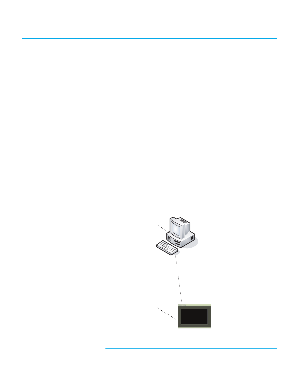
This manual provides information for configuring the PanelView™ 800
(a)
terminal. You can configure the terminal, through a web browser
on a
computer connected to the terminal, or through Connected Components
Workbench™ software. This manual also provides information on how to
troubleshoot the PanelView 800 terminal.
Topic Page
Summary of Changes 9
Who Should Use this Manual 9
Firmware Upgrades 10
Additional Resources 10
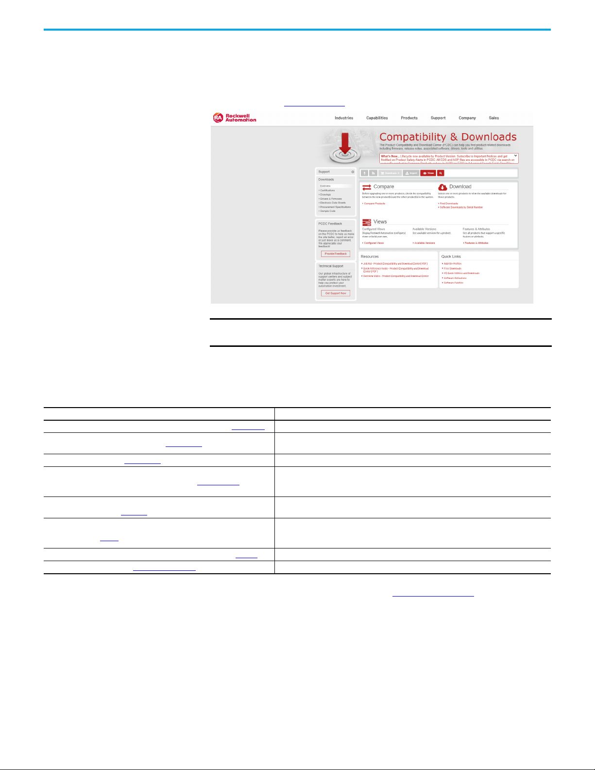
Download firmware, associated files (such as AOP, EDS, and DTM), and access
product release notes from the Product Compatibility and Download Center at
rok.auto/pcdc
.
This publication contains the following new or updated information. This list
includes substantive updates only and is not intended to reflect all changes.
Topic Page
Updated template throughout
Updated information on the supported operating systems 46
Updated section Downloading Applications 53
Added section Import Tags From a Controller 67
Added section Assign Tags From a CompactLogix 5370 Controller 70
Added section Export and Import a Language List 70
Added section Update Tag Names 72
Added section Animation Configuration 73
Added section Time Entry Data Type Support 74
Added section View List of Objects 75
Updated section Manage User Account Settings 80
Who Should Use this Manual
Use this manual if you are responsible for configuring, operating, or
troubleshooting the PanelView 800 terminals.
No special knowledge is required to understand this manual or operate the
terminal.
Equipment installers must be familiar with standard panel installation
techniques.
(a) The web browser feature is not supported on PanelView 800 terminals from firmware
revision 3.011 onwards.
Rockwell Automation Publication 2711R-UM001H-EN-E - April 2021 9
Page 10
Firmware Upgrades
To receive firmware upgrades and other downloads for your PanelView 800
terminal:
• Contact your local Allen-Bradley distributor or sales representative.
• Go to the Rockwell Automation Product Compatibility and Download
Center at rok.auto/pcdc
.
IMPORTANT You must sign in to the Rockwell Automation website before downloading
a firmware revision.
Additional Resources
These documents contain additional information concerning related products
from Rockwell Automation.
Resource Description
PanelView 800 HMI Terminals Installation Instructions, publication 2711R-IN001
EtherNet/IP Network Devices User Manual, ENET-UM006
Ethernet Reference Manual, ENET-RM002
System Security Design Guidelines Reference Manual, SECURE-RM001
Industrial Components Preventive Maintenance, Enclosures, and Contact Ratings
Specifications, publication IC-TD002
Safety Guidelines for the Application, Installation, and Maintenance of Solid-state
Control, publication SGI-1.1
Industrial Automation Wiring and Grounding Guidelines, publication 1770-4.1
Product Certifications website, rok.auto/certifications. Provides declarations of conformity, certificates, and other certification details.
You can view or download publications at rok.auto/literature
Provides instructions for installing a PanelView 800 terminal.
Describes how to configure and use EtherNet/IP™ devices to communicate on the EtherNet/IP
network.
Describes basic Ethernet concepts, infrastructure components, and infrastructure features.
Provides guidance on how to conduct security assessments, implement Rockwell Automation
products in a secure system, harden the control system, manage user access, and dispose of
equipment.
Provides a quick reference tool for Allen-Bradley® industrial automation controls and
assemblies.
Designed to harmonize with NEMA Standards Publication No. ICS 1.1-1987 and provides general
guidelines for the application, installation, and maintenance of solid-state control in the form of
individual devices or packaged assemblies incorporating solid-state components.
Provides general guidelines for installing a Rockwell Automation industrial system.
.
10 Rockwell Automation Publication 2711R-UM001H-EN-E - April 2021
Page 11
Chapter 1
2
3
4
6176
5
8
9
10
11
12
Overview
Chapter Objectives This chapter gives an overview of the PanelView 800 terminals.
• About the terminals
• How to connect browser
• PanelView Explorer
•How to display help
• Peripheral connection
• Catalog number configuration
About the Terminals PanelView 800 terminals are operator interface devices for monitoring and
controlling devices attached to a controller. HMI applications are created
using Connected Components Workbench software, then downloaded to the
terminal.
(a)
(b)
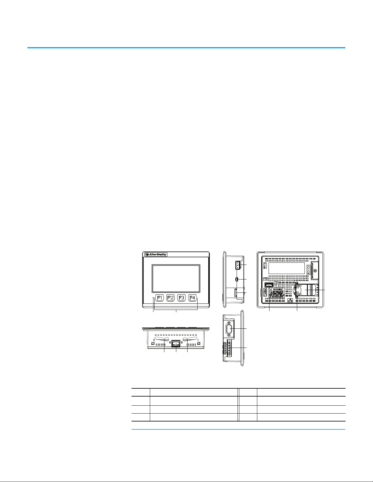
PanelView 800 Terminal – 2711R-T4T
PanelView terminal 2711R-T4T Description
Item Description Item Description
1
2 Touch display, function keys 8 RS-232 port
3 24V DC power input 9 RS-422 and RS-485 port
Power status LED
(1)
7 10/100 Mb Ethernet port
(a) The web browser feature is not supported on PanelView 800 terminals from firmware
Rockwell Automation Publication 2711R-UM001H-EN-E - April 2021 11
revision 3.011 onwards.
(b) The PanelView Explorer feature is not supported on PanelView 800 terminals from firmware
revision 3.011 onwards.
Page 12

Chapter 1 Overview
1
5643
8
7
10
92
3
11
12
PanelView terminal 2711R-T4T Description (Continued)
Item Description Item Description
4
USB device port
5 microSD™ (Secure Digital) card slot 11 Diagnostic status indicator
6 Mounting slots 12 Replaceable real-time clock battery
(1) The Power Status LED is red when in screen saver or dimmer mode and green when in normal (operational) mode.
(2) The USB device port is not intended for Customer use.
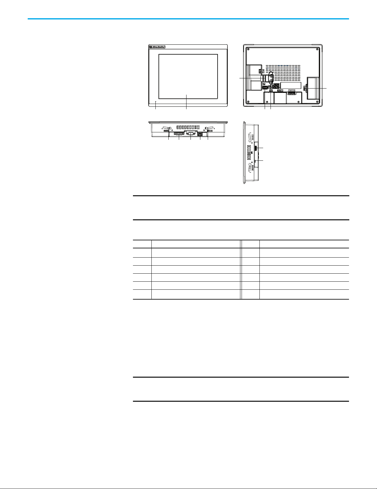
PanelView 800 Terminals – 2711R-T7T
(2)
10 USB host port
PanelView 800 Terminals 2711R-T7T Description
Item Description Item Description
1
Power status LED
2 Touch display 8 USB host port
3 Mounting slots 9 Diagnostic status indicator
4 RS-422 and RS-485 port 10 microSD (Secure Digital) card slot
5 RS-232 port 11 24V DC power input
6 10/100 Mb Ethernet port 12
(1) The Power Status LED is red when in screen saver or dimmer mode and green when in normal (operational) mode.
(2) The USB device port is not intended for Customer use.
(1)
7 Replaceable real-time clock battery
USB device port
(2)
12 Rockwell Automation Publication 2711R-UM001H-EN-E - April 2021
Page 13
PanelView 800 Terminal – 2711R-T10T
1
5643
8
7
10
9
2
11
12
3
Chapter 1 Overview
IMPORTANT Analog touch screens are intended for single presses at a time. If the
touch screen is pressed in two locations at the same time, the presses are
averaged as a single press in-between the two locations
PanelView 800 Terminal 2711R-T10T Description
Item Description Item Description
1
2 Touch display 8 USB host port
3 Mounting slots 9 Diagnostic status indicator
4 RS-422 and RS-485 port 10 microSD (Secure Digital) card slot
5 RS-232 port 11 24V DC power input
6 10/100 Mb Ethernet port 12
(1) The Power Status LED is red when in screen saver or dimmer mode and green when in normal (operational) mode.
(2) The USB device port is not intended for Customer use.
Power status LED
(1)
7 Replaceable real-time clock battery
USB device port
(2)
How to Connect Browser The terminals can be connected to a browser using an Ethernet network
connection. You must enter the IP address of the PanelView 800 terminal into
the address field of your browser. You can find the IP address on the terminal
configuration screen under Communications.
IMPORTANT
The web browser feature is only supported on PanelView 800 terminals
with firmware revision 2.020 or earlier. It is not supported from
firmware revision 3.011 onwards.
Rockwell Automation Publication 2711R-UM001H-EN-E - April 2021 13
Page 14

Chapter 1 Overview
USB Device Port
The PanelView 800 terminals have a USB device port to support
communication with the terminal using TCP/IP.
IMPORTANT
The USB device port is for maintenance only and is not intended for normal
runtime operation.
The USB device port is not intended for Customer use.
Ethernet Port
The PanelView 800 terminals have an Ethernet port. The Ethernet port
supports both static IP addresses and Dynamic Host Configuration Protocol
(DHCP) assigned IP addresses. If using static IP addressing, then you
manually set the IP address, the subnet mask, and the default gateway. If using
DHCP, then the server automatically assigns an IP address, the subnet mask,
the default gateway, and the DNS and WINS server.
IMPORTANT
If a terminal is set for DHCP and is not on a network or is on a network that
does not have a DHCP server (or the server is not available), it will
automatically assign itself an Automatic Private IP address (or auto IP
address). The auto IP address is in the range of 169.254.0.0 through
169.254.255.255.
The terminal makes sure the auto IP address is unique from any other auto
IP address of other devices on the network. The terminal can now
communicate with other devices on the network that have IP addresses in
the 169.254.xxx.xxx range (and a subnet mask of 255.255.0.0).
PanelView Explorer PanelView Explorer is the browser interface for interacting with PanelView
800 terminals. Through this interface you can configure the terminal settings,
transfer files, test, and run applications. See Appendix F
on using PanelView Explorer.
IMPORTANT
The PanelView Explorer feature is only supported on PanelView 800
terminals with firmware revision 2.020 or earlier. It is not supported from
firmware revision 3.011 onwards.
for more information
Peripheral Connection PanelView 800 terminals have a USB host port. You can power USB
peripherals directly from the PanelView 800 terminal. If the USB peripheral is
not powered directly from the PanelView USB port either:
• install the USB peripheral in the same enclosure as the PanelView
terminal and make sure it is connected to the same ground system.
• connect to the USB peripheral through a galvanically isolated hub.
WARNING: If you connect or disconnect the communications cable with power
applied to this module or any device on the network, an electrical arc can occur.
This could cause an explosion in hazardous location installations.
Be sure that power is removed or the area is nonhazardous before proceeding.
14 Rockwell Automation Publication 2711R-UM001H-EN-E - April 2021
Page 15
Chapter 1 Overview
WARNING: If you connect or disconnect the USB cable with power applied to
this module or any device on the USB network, an electrical arc can occur. This
could cause an explosion in hazardous location installations.
Be sure that power is removed or the area is nonhazardous before proceeding.
ATTENTION: Removing the USB flash drive or microSD card, from the
PanelView 800 terminal, while a firmware upgrade is in process, could
corrupt the firmware and make the terminal unusable. Take precautions to
prevent the USB flash drive or microSD card from being accidentally
disconnected. Also, do not power off the terminal while a firmware upgrade is
in progress.
USB hubs can produce unexpected behaviors and as a result are not
recommended.
Catalog Number Configuration
These are the available PanelView 800 terminals.
Cat. No. Operator Input Size Display Type
2711R-T4T Touch screen and function keys 4 in. Color TFT
2711R-T7T Touch screen 7 in. Color TFT
2711R-T10T Touch screen 10 in. Color TFT
Rockwell Automation Publication 2711R-UM001H-EN-E - April 2021 15
Page 16

Chapter 1 Overview
Notes:
16 Rockwell Automation Publication 2711R-UM001H-EN-E - April 2021
Page 17
Chapter 2
Running
Internet Explorer or
Firefox browser
Ethernet
connectivity
On Terminal
Configuration
Configure the Terminal
Chapter Objectives This chapter covers topics that show how to configure your PanelView 800
terminal.
• Configuration interfaces
• Terminal settings
• Managing applications and files
• Creating applications
• Upload and Download applications
• Transferring applications
• Transferring user-defined objects
Configuration Interfaces The terminal can be configured from either the browser interface
configuration screens on the terminal. The browser interface requires a
computer browser connected to the terminal's web service through an
Ethernet network connection. The configuration data for a terminal refers to
the collection of all of the system interface parameters.
Access to the Terminal’s Configuration
(a)
or the
(a) The web browser feature is not supported on PanelView 800 terminals from firmware
revision 3.011 onwards. For more information about the PanelView Explorer feature, see
Appendix F.
Rockwell Automation Publication 2711R-UM001H-EN-E - April 2021 17
Page 18
Chapter 2 Configure the Terminal
Main
File Manager
System Information
Current Application
Config Language Date and Time
Day Hour
Reset Terminal
Goto
14 10
Month Minute
1 30
Year Second
2015 56
English
Português
Français
Italiano
Deutsch
Español
简体中文
Terminal Setting
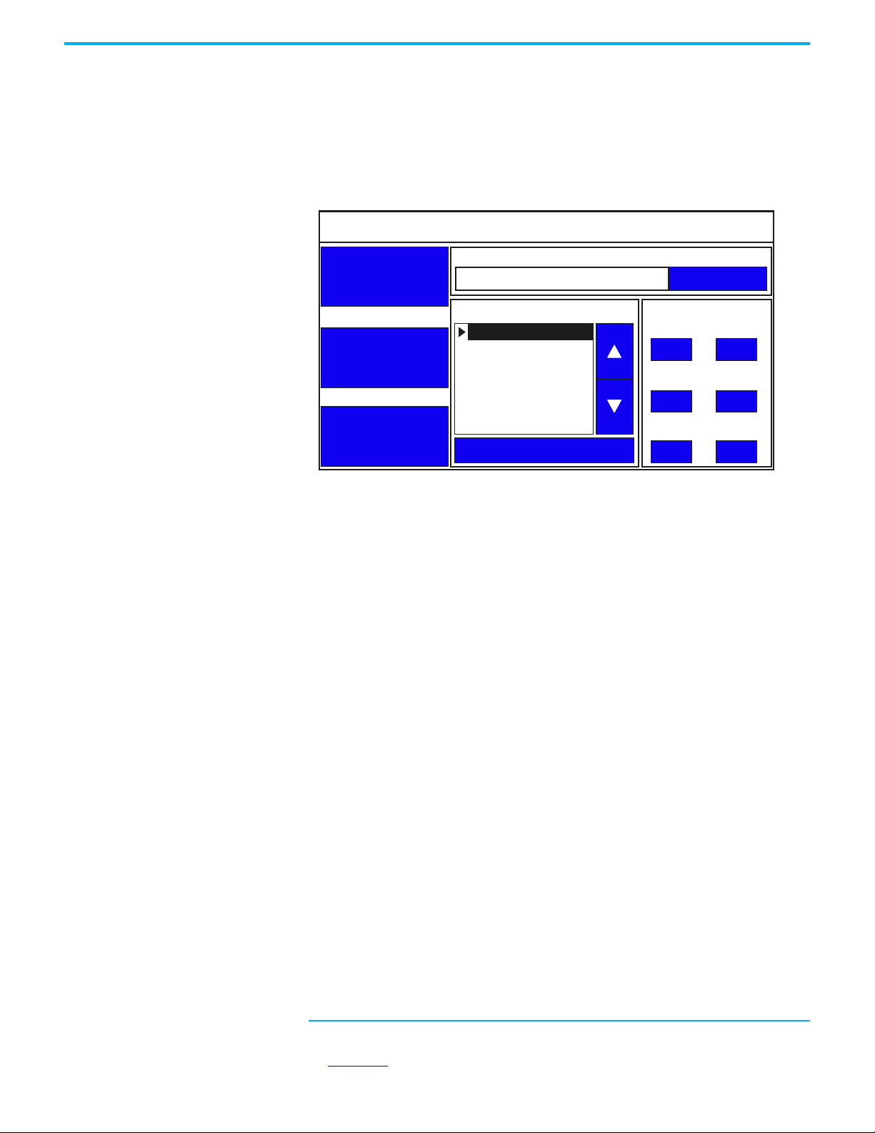
Configure Using the Terminal
The on-terminal interface lets you make changes to the terminal settings. The
menu is displayed on the left side of the terminal screen. Changes can be made
whether an application is running or not running.
Terminal Interface Main Menu
Configure Terminal Settings Terminal settings can be configured either through the PanelView Explorer
18 Rockwell Automation Publication 2711R-UM001H-EN-E - April 2021
browser
Adjusting Settings on the Terminal
From the terminal, you can view and edit the terminal settings. Most settings
take effect immediately.
By clicking the menu items on the screen, you can:
• change the terminal language.
• change the current date and time.
• reboot or reset the terminal.
• import or export an application.
• change the startup application.
• copy or edit recipes of an application.
• copy the alarm history of an application.
• change the controller settings for an application.
• change Ethernet network settings.
• change Virtual Network Computing (VNC) settings.
• change communication port settings.
• change the FTP server settings.
(a) The PanelView Explorer feature is not supported on PanelView 800 terminals from firmware
revision 3.011 onwards. For more information about the PanelView Explorer feature, see
Appendix F.
(a)
interface or through the on-terminal interface.
Page 19
Chapter 2 Configure the Terminal
Main
File Manager
System Information
Current Application
Config Language Date and Time
Day Hour
Reset Terminal
Goto
14 10
Month Minute
1 30
Year Second
2015 56
English
Português
Français
Italiano
Deutsch
Español
简体中文
Terminal Setting
• adjust the display brightness.
• calibrate the touch screen, if supported.
• change the display orientation.
• configure screen saver settings.
• delete fonts from the terminal.
• change the error alert display settings.
• configure print settings.
• view system information.
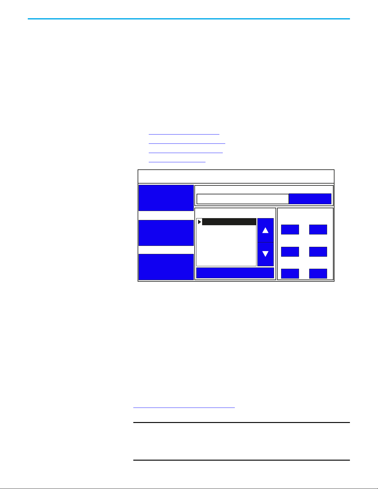
Main Configuration Settings You can perform the following actions on the main configuration screen:
• Goto
• Select a Terminal Language
• Change the Date and Time
• Reboot the Terminal
Current Application
Goto Current Application
The current application field displays the name of the application that is
currently running on the terminal. You can press the Goto button to switch to
that application. If no application is running, the field is empty.
Select a Terminal Language
You can change the terminal display language. The terminal is shipped with
English, Portuguese, French, Italian, German, Spanish, and Chinese fonts
installed. Korean is supported but you must first install the Korean font. See
Add Fonts to the Terminal
onto the terminal.
IMPORTANT
Rockwell Automation Publication 2711R-UM001H-EN-E - April 2021 19
on page 63 for information on how to install the font
At runtime, diagnostic messages appear in the same language as the
application if the application language is English, Portuguese, French,
Italian, German, Spanish, Chinese, or Korean. For all other languages, the
diagnostic messages appear in the configuration language set on the
terminal.
Page 20
Chapter 2 Configure the Terminal
Main
File Manager
System Information
Current Application
Config Language Date and Time
Day Hour
Reset Terminal
Goto
14 10
Month Minute
1 30
Year Second
2015 56
English
Português
Français
Italiano
Deutsch
Español
简体中文
Terminal Setting
7 8 9
4 5 6
1 2 3
0 -
Esc
14
Follow these steps to change the terminal language from the terminal.
1. Go to the main configuration screen.
2. To select the language, use the up and down arrow keys.
The change takes effect immediately.
Change the Date and Time
You can adjust the current date and time for terminal operations. The time is
set in 24-hour format. If using PanelView Explorer, you can also set the
terminal to automatically adjust the time for daylight savings time.
Follow these steps to change the terminal date and time from the terminal.
1. Go to the main configuration screen.
2. Click the number next to what you want to change under the 'Date and
Time' section.
A numeric keypad is displayed.
3. Select the numbers that you want and press the Enter key.
20 Rockwell Automation Publication 2711R-UM001H-EN-E - April 2021
Reboot the Terminal
You can restart the terminal without having to disconnect and reapply power.
After a reset, the terminal performs series of startup tests and then either
enters configuration mode or runs the startup application.
Follow these steps to reboot the terminal from the terminal.
1. Go to the main configuration screen.
2. Press Reset Terminal.
3. Press Yes to confirm.
Page 21
Chapter 2 Configure the Terminal
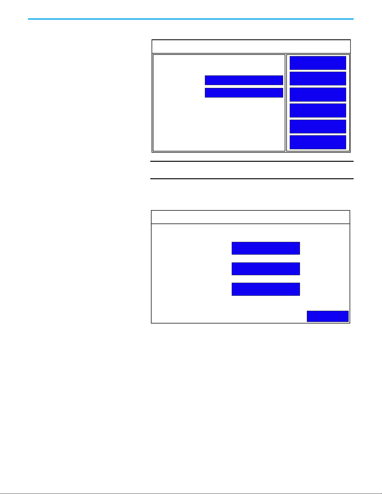
File Manager Settings On the main configuration screen, press File Manager to go to the File
Manager screen.
File Manager
Source: To:
Internal
PV800_App1
PVcApplication1
Copy Alarm HistoryRecipe
Startup Application
IMPORTANT
Internal
Controller Settings
Reset
The Stop Application button is only available in firmware revision
Copy
Delete
Set As Startup
Run
Stop Application
Main
3.011 onwards.
IMPORTANT
The Controller Settings button is only available in firmware revision
4.011 onwards.
You can perform the following actions under File Manager settings:
• Export an Application
• Import an Application
• Change the Startup Application
• Copy or Edit Recipes
• Copy Alarm History
• Change Controller Settings for an Application
Export an Application
During an export, the application file is transferred from internal storage of
the terminal to a USB flash drive or microSD card. The application is saved
with its default name and “.cha” file type.
Follow these steps to export an application from the terminal.
1. Go to the File Manager screen.
2. Select Internal as the Source location of the application.
3. Select the location to copy the application from the To list, either USB or
microSD card.
4. Select the name of the application from the Name list.
5. Press Copy.
Rockwell Automation Publication 2711R-UM001H-EN-E - April 2021 21
Page 22

Chapter 2 Configure the Terminal
Import an Application
During an import, the application file (.cha) is transferred from a USB flash
drive or microSD card to the internal storage of the terminal. The transfer
operation communicates with the terminal to import the file.
You cannot overwrite an application while the application is running. You
must unload the current application before overwriting the application. You
can import applications while another is running.
Follow these steps to import an application from the terminal.
1. Go to the File Manager screen.
2. Select the source location of the application from the Source list, either
USB or microSD card.
3. Select Internal as the To location to copy the application.
4. Select the name of the application from the Name list.
5. Press Copy.
The application is transferred to the internal storage of the terminal.
If an application with the same name exists in internal storage, you are asked
if you want to replace the existing application.
Change the Startup Application
You can select or change the application that runs on the terminal each time
the terminal starts up. Only applications in the internal storage of the terminal
can be run or set as a Startup Application.
IMPORTANT
Follow these steps to select or change the startup application from the
terminal.
1. Go to the File Manager screen.
2. Select Internal from the Source list.
3. Select the name of the startup application from the Name list.
4. Click Set As Startup.
If the application list is empty, the run, copy, delete, and set as startup
functions will not perform any action.
Copy or Edit Recipes
You can copy recipes from a USB device or microSD card to an application on
the terminal, or from the terminal to a USB device or microSD card. You can
also edit the name of a recipe in an application, or delete the recipe from an
application.
IMPORTANT
22 Rockwell Automation Publication 2711R-UM001H-EN-E - April 2021
To perform a copy or edit operation on a recipe of an application, that
application must be unloaded or not running.
Page 23
Chapter 2 Configure the Terminal
Copy Recipe
Back
Copy
USB
Copy From
To:
Copy
SD
Copy To
From:
PV800_App1
PV800_App1
Recipe1
Recipe2
Recipe3
Recipe6
Recipe7
Recipe5
You cannot perform these actions on a password protected application.
Copy a Recipe
Follow these steps to copy a recipe.
1. Go to the File Manager screen.
2. Select the application that you want to copy the recipe, then press Recipe.
Recipe
Copy Recipe Edit Recipe
Back
3. Press Copy Recipe.
4. Select the location where you want to copy the recipe from, or copy the
recipe to.
5. Select the recipe from the recipe list.
6. Press Copy.
IMPORTANT
Copying out a recipe from a design secured application is not allowed.
Rockwell Automation Publication 2711R-UM001H-EN-E - April 2021 23
Page 24
Chapter 2 Configure the Terminal
Edit a Recipe
Follow these steps to rename or delete a recipe.
1. Go to the File Manager screen.
2. Select the application that you want to edit the recipe, then press Recipe.
Recipe
Copy Recipe Edit Recipe
Back
3. Press Edit Recipe.
Edit Recipe
Application Name:
Recipe1
Recipe2
Recipe3
Recipe5
Name:
The name of the currently loaded application is displayed, as well as a list
of the recipes for that application.
4. Select the recipe from the recipe list.
5. Press Delete if you wish to delete the recipe, then press OK to confirm.
IMPORTANT
PV800_App1
Delete
Recipe1
Back
Renaming of a recipe in a design secured application is not allowed.
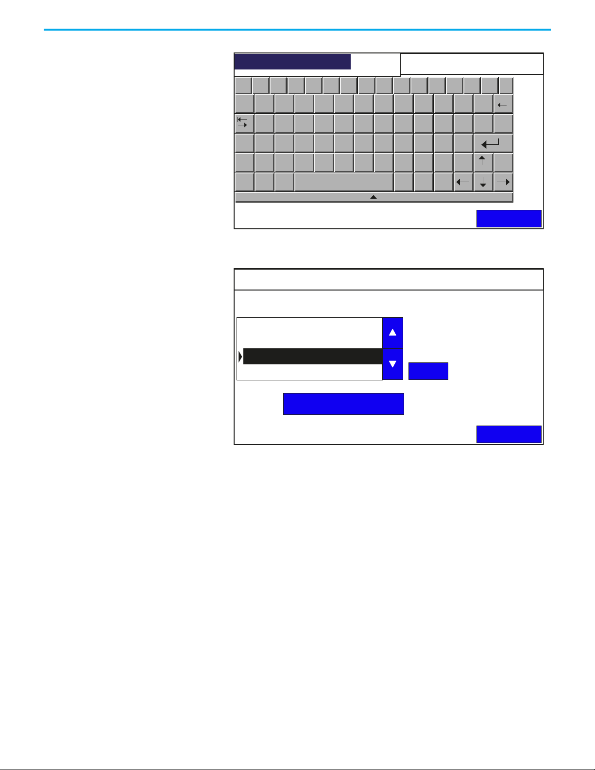
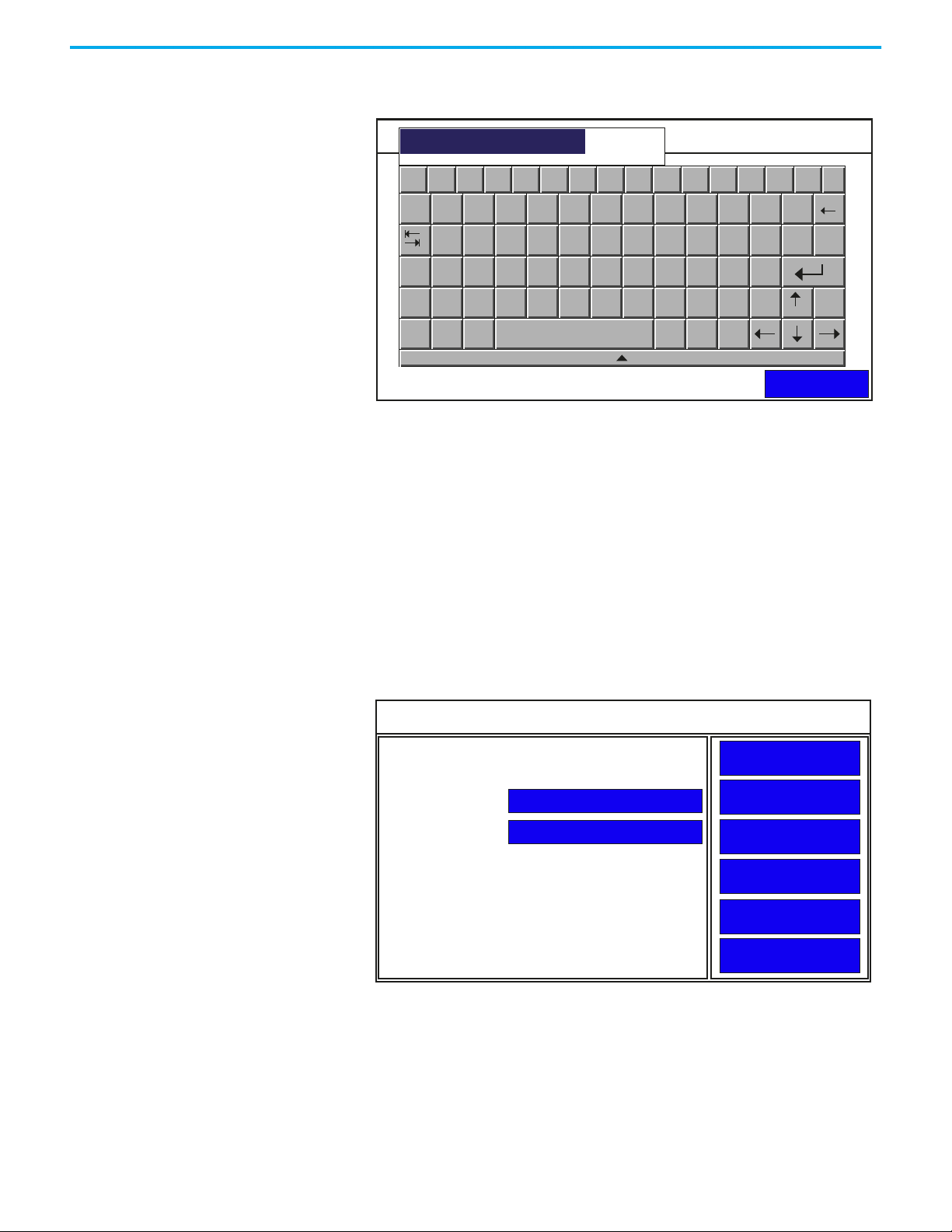
6. Press the blue area next to Name to change the name of the recipe.
IMPORTANT
Deletion of a recipe in a design secured application is not allowed.
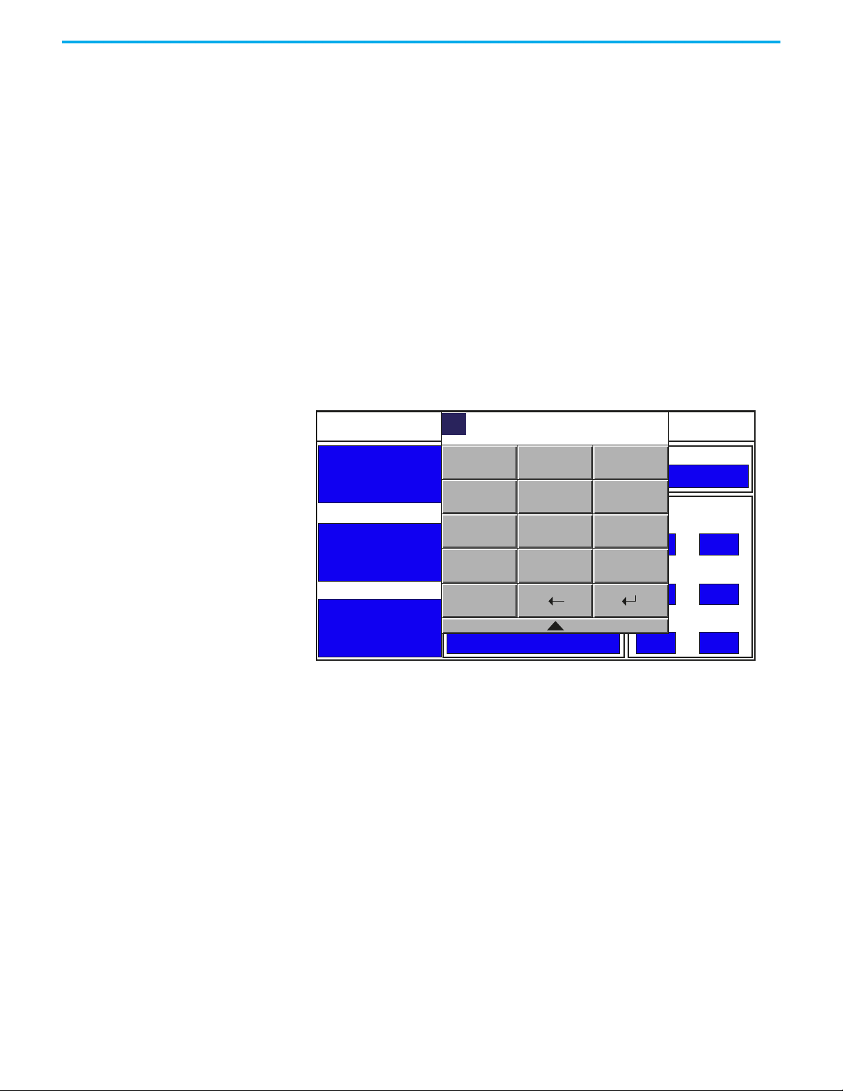
7. Type in the desired name using the on-screen keypad, then press Enter.
24 Rockwell Automation Publication 2711R-UM001H-EN-E - April 2021
Page 25
Chapter 2 Configure the Terminal
Recipe4
Esc F1 F2 F3 F4 F5 F6 F7 F8 F9 F10 F11 F12 Home End
Application Name:
1 2 3
`
Recipe1
q w e
Recipe2
Recipe3
a s d
Caps
Recipe4
z x c
Shift
Win
Ctrl
Name:
Alt
Recipe1
PV800_App1
4
r
f
v
Edit Recipe
5 6
t y
g h
b n
7
u
m
9
8
o
i
k
ins
,
l
Delete
.
del
j
- =
0
p
[ ]
;
’
\
/
Back
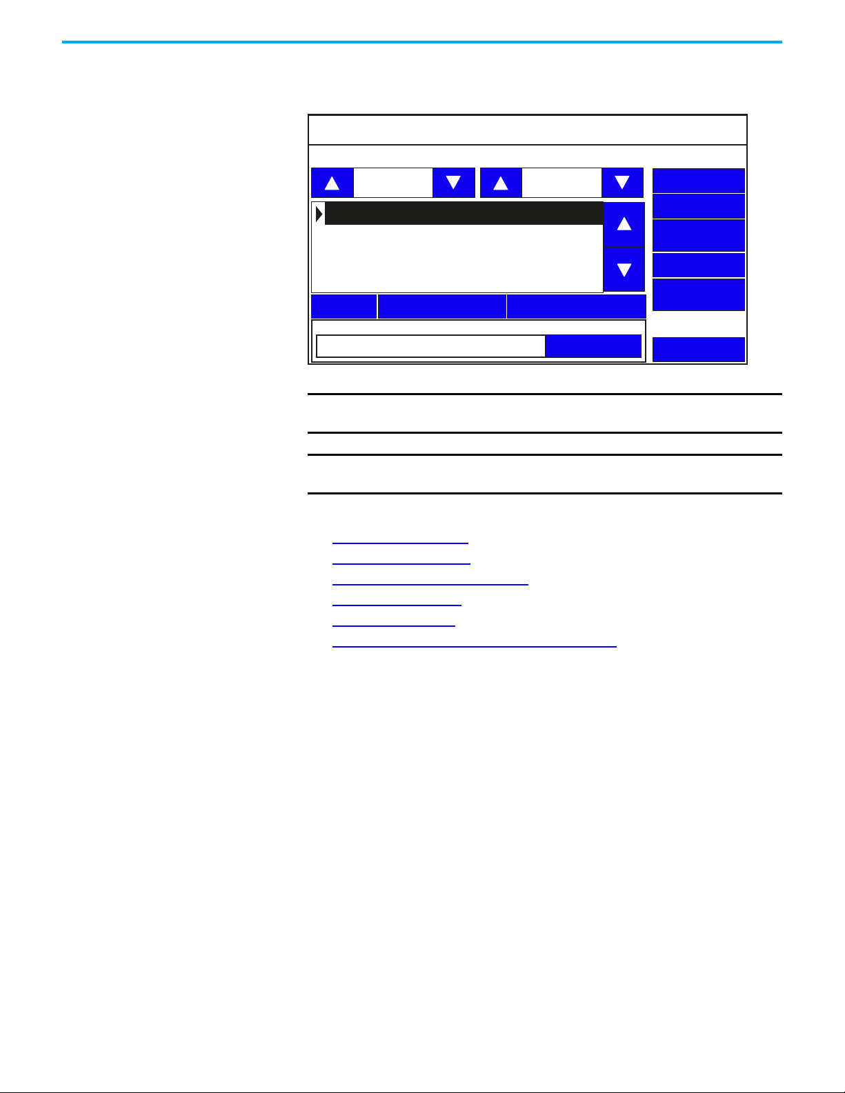
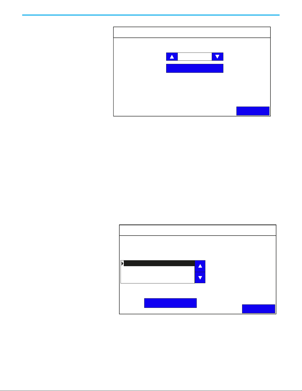
8. The recipe name is changed and the recipe list is automatically resorted
alphanumerically.
Edit Recipe
Application Name:
Recipe2
Recipe3
Recipe4
Recipe5
PV800_App1
Delete
Name:
Recipe4
Back
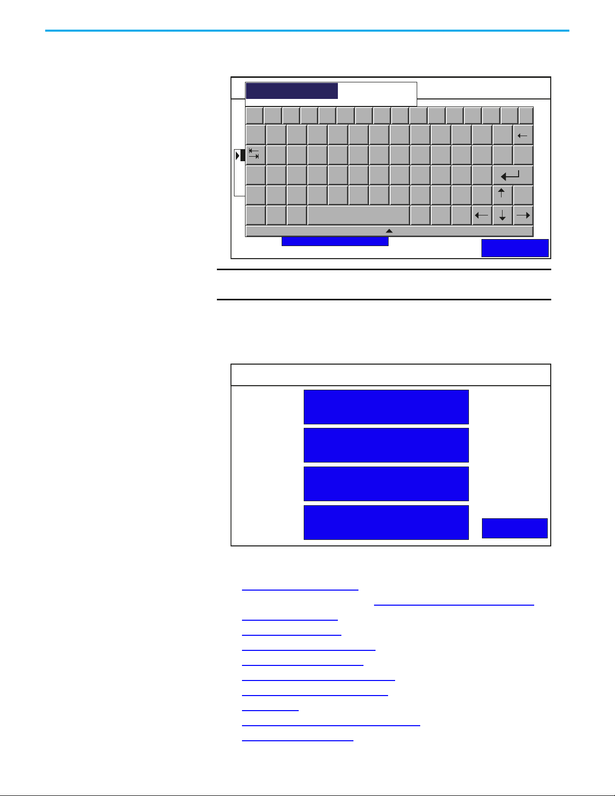
Copy Alarm History
You can copy the alarm history of an application on the terminal into a USB or
microSD card.
Follow these steps to copy the alarm history.
1. Go to the File Manager screen.
2. Use the up and down arrow keys to select the application that you want to
copy the alarm history from.
3. Press Copy Alarm History.
Rockwell Automation Publication 2711R-UM001H-EN-E - April 2021 25
Page 26
Chapter 2 Configure the Terminal
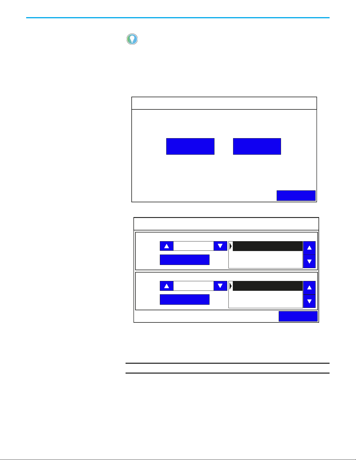
Copy Alarm History
Back
Copy
USB
From: PV800_App1
To:
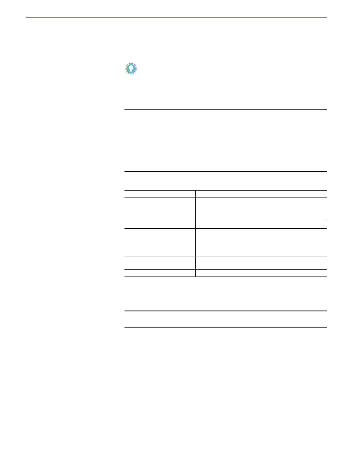
4. Select the location to copy the alarm history from the To list, either USB
or microSD card.
5. Press Copy.
Change Controller Settings for an Application
You can change the network address or node address of the controller in your
application using the terminal. This feature is available in firmware revision
4.011 onwards.
Follow these steps to change the network address or node address of the
controller for your application from the terminal.
1. Go to the File Manager screen.
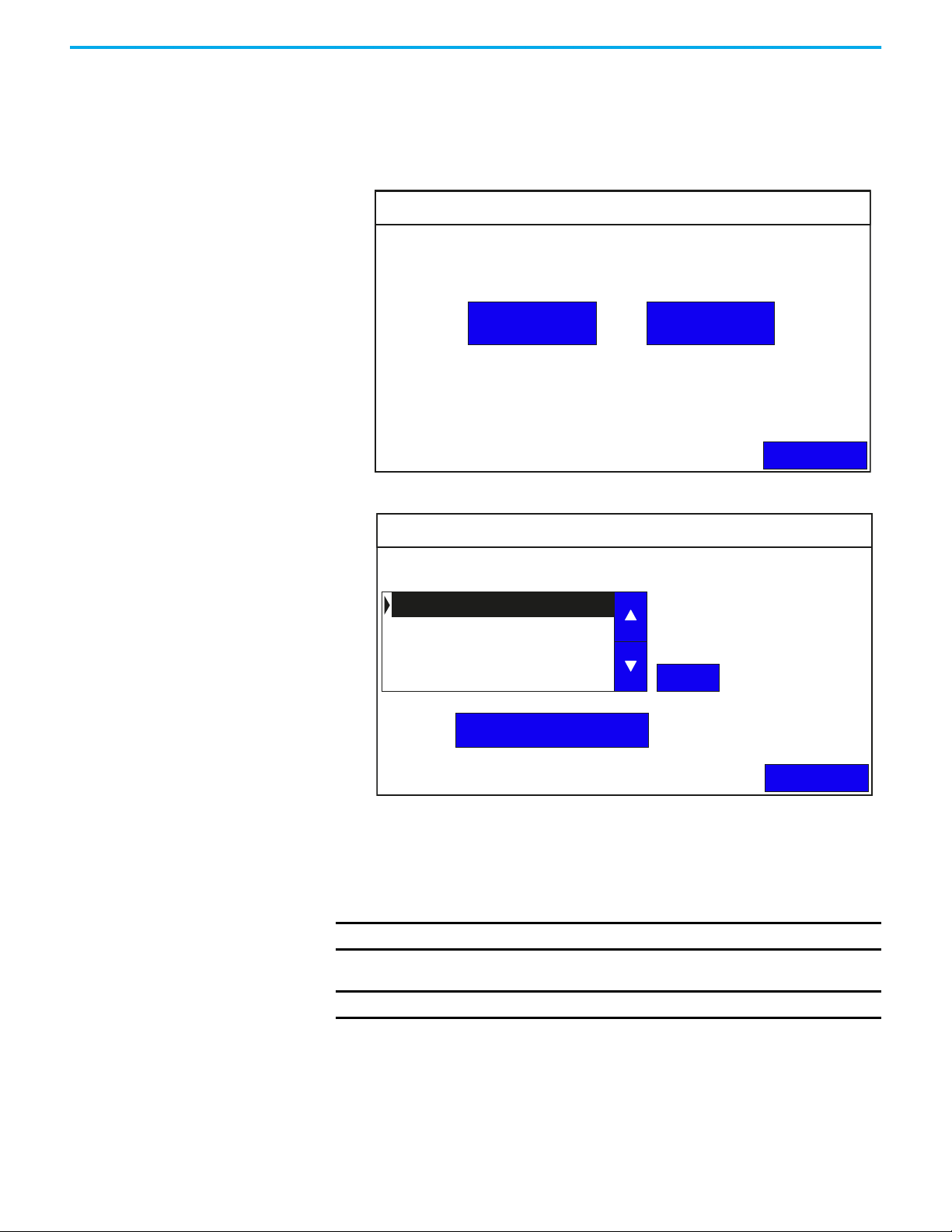
2. Press Controller Settings.
Controller Settings
Application Name: PV800_App1
Protocol: Ethernet | Allen-Bradley MicroLogix/ENI
PLC-1 : 10.116.37.12
Type: MicroLogix 1400
Address:
10.116.37.12
26 Rockwell Automation Publication 2711R-UM001H-EN-E - April 2021
3. Press the blue area next to Address to change the address.
Back
Page 27
Chapter 2 Configure the Terminal
Controller Settings
Back
Application Name: PV800_App1
Protocol: Ethernet | Allen-Bradley MicroLogix/ENI
Type: MicroLogix 1400
Address:
PLC-1 : 10.116.37.12
10.116.37.12
`
Esc F1 F2 F3 F4 F5 F6 F7 F8 F9 F10 F11 F12 Home End
1 2 3
4
5 6
7
8
9
0
- =
q w e
r
t y
u
i
o
p
[ ]
\
10.116.37.12
Caps
a s d
f
g h
j
k
l
;
’
Shift
z x c
v
b n
m
,
.
/
Ctrl
Win
Alt
ins
del
Terminal Setting
Communication
Main
Display
Error Alert Display Settings
Print Settings
Type in the desired IP address using the on-screen keypad, then press
Enter.
IMPORTANT
You cannot change the controller setting for an application that
is running.
Terminal Settings On the main configuration screen, press Terminal Settings to go to the
Terminal Settings screen.
You can perform the following actions under Terminal Settings:
• Change Ethernet Settings
• Configure VNC Settings (see Configure VNC Settings on page 90)
• Change Port Settings
• Enable the FTP Server
• Adjust the Display Brightness
• Calibrate the Touch Screen
• Changing the Display Orientation
• Configure Screen Saver Settings
• Delete Fonts
• Change the Error Alert Display Settings
Rockwell Automation Publication 2711R-UM001H-EN-E - April 2021 27
• Configure Print Settings
Page 28
Chapter 2 Configure the Terminal
Change Ethernet Settings
You can establish an Ethernet connection between the connected PanelView
800 terminal and computer using the Ethernet port on the terminal.
You cannot change the Ethernet settings from PanelView Explorer. If you want to
change this setting, you must do so from the terminal configuration screens.
For the Ethernet port, IP addresses can be set dynamically by the network if
Dynamic Host Configuration Protocol (DHCP) is enabled. If DHCP is disabled,
the IP addresses must be entered manually.
IMPORTANT
If a terminal is set for DHCP and is not on a network or is on a network that
does not have a DHCP server (or the server is not available), it will
automatically assign itself an Automatic Private IP address (or auto IP
address). The auto IP address is in the range of
169.254.0.0…169.254.255.255.
The terminal makes sure that the auto IP address is unique from any other
auto IP address of other devices on the network. The terminal can now
communicate with other devices on the network that have IP addresses in
the 169.254.xxx.xxx range (and a subnet mask of 255.255.0.0).
Ethernet Settings
Parameter Description
Read-only field that defines the MAC ID of the PanelView 800 terminal. Each
MAC ID
Network Device Name Unique name that identifies the terminal on the network.
IP address
Subnet Mask
Default Gateway Optional address that is formatted like the IP address.
Ethernet device has a unique MAC ID.
The MAC ID is shown in PanelView Explorer, and the Communication terminal
screen from firmware revision 4.011 onwards.
Unique address that identifies the terminal on the Ethernet network.
The format of the IP address is xxx.xxx.xxx.xxx, for example, 10.90.95.30 The
range of values for the first set of decimal numbers is 1…255 unless all fields
are set to 000. The range of values for the last three sets of decimal numbers
is 0…255.
Address that must be identical to the server subnet mask. The subnet mask
is formatted like the IP address.
If DHCP is enabled for the Ethernet port, the current fields show the IP
addresses assigned by the network. You can assign IP addresses manually by
disabling DHCP and entering addresses in the static fields.
IMPORTANT
If the Ethernet port is disabled, you cannot set a static IP address for the
terminal. The terminal prompts an alert (ID: 2058) when you try to do so.
Follow these steps to set a static IP address for the terminal’s Ethernet port
from the terminal.
1. Go to the Terminal Settings screen.
28 Rockwell Automation Publication 2711R-UM001H-EN-E - April 2021
Page 29
2. Press Communication.
Communication
Disable DHCP
Set Static IP Address
VNC Settings
Port Settings
FTP Settings
Back
PV800T7T
0
Protocol: *
Status: Unavailable
Device Name:
Node Address:
IP Mode: DHCP
IP Address: 0.0.0.0
Mask: 0.0.0.0
Gateway: 0.0.0.0
MAC Address: XX:XX:XX:XX:XX
Chapter 2 Configure the Terminal
IMPORTANT
The MAC address value display is only available in firmware
revision 3.011 onwards.
3. Press Disable DHCP.
The IP Mode now displays the text "Static".
4. Press Set Static IP address screen appears.
Static IP Address
IP Address:
Mask:
Gateway:
5. Press the blue area next to IP address to enter an IP address in the Static
IP address field.
0.0.0.0
0.0.0.0
0.0.0.0
Back
Rockwell Automation Publication 2711R-UM001H-EN-E - April 2021 29
Page 30
Chapter 2 Configure the Terminal
Type in the desired IP address using the on-screen keypad, then press
Enter.
169.254.158.177
Esc F1 F2 F3 F4 F5 F6 F7 F8 F9 F10 F11 F12 Home End
IP Address:
1 2 3
`
q w e
Mask:
a s d
Caps
z x c
Shift
Ctrl
Win
Gateway:
Alt
Static IP Address
5 6
4
r
t y
f
g h
v
b n
0.0.0.0
7
u
0.0.0.0
j
m
0.0.0.0
8
k
ins
9
o
i
l
.
,
del
- =
0
p
[ ]
;
’
/
Back
6. Repeat step 5 to enter the address for the Subnet Mask and Gateway
Address.
Change Port Settings
You can control access to the terminal through Ethernet or Serial
communication by enabling or disabling the respective port.
\
Follow these steps to enable or disable the communication port on the
terminal.
1. Go to the Terminal Settings screen.
2. Press Communication.
Communication
Protocol: *
Status: Unavailable
Device Name:
Node Address:
IP Mode: DHCP
IP Address: 0.0.0.0
Mask: 0.0.0.0
Gateway: 0.0.0.0
MAC Address: XX:XX:XX:XX:XX
PV800T7T
0
Disable DHCP
Set Static IP Address
VNC Settings
Port Settings
FTP Settings
Back
30 Rockwell Automation Publication 2711R-UM001H-EN-E - April 2021
Page 31

3. Press Port Settings.
Chapter 2 Configure the Terminal
Port Settings
Ethernet:
Serial:
Enable
Enable
Back
4. The Ethernet and Serial ports are enabled by default. Press Enable for the
respective port to disable it, then press OK to confirm.
IMPORTANT
From firmware revision 5.011 onwards, the port settings can only be
enabled or disabled when no application is running on the terminal.
IMPORTANT
If the Ethernet port is disabled, you cannot set a static IP address for the
terminal. The terminal prompts an alert (ID: 2058) when you try to do so.
IMPORTANT
If the Ethernet port is disabled, the IP address, Mask, and Gateway
settings display a “*”.
Communication
Protocol: *
Status: Unavailable
Device Name:
Node Address:
IP Mode:
IP Address: *
Mask: *
Gateway: *
MAC Address: XX:XX:XX:XX:XX
PV800T7T
0
Disable DHCP
Set Static IP Address
VNC Settings
Port Settings
FTP Settings
Back
Enable the FTP Server
You can connect to a PanelView 800 terminal using an FTP (File Transfer
Protocol) client such as a web browser, PC file explorer, or third-party FTP
software. This gives you read-only access to the Alarm History, Datalog, and
Recipe folders on the terminal. To access the contents of these folders,
permissions must be configured in Connected Components Workbench
software. See Configure FTP Settings
The Alarm History folder contains only the alarm history of the current running
application on the terminal.
Rockwell Automation Publication 2711R-UM001H-EN-E - April 2021 31
on page 57.
Page 32

Chapter 2 Configure the Terminal
After you have established an FTP connection to the terminal, you can copy the
contents of the folders out from the terminal to your PC. The FTP server on the
terminal is disabled by default.
IMPORTANT
The terminal supports only one FTP connection. If another connection is
attempted, it is rejected and no notification is given. The behavior varies
from one FTP client to another.
IMPORTANT
An FTP connection cannot be established while the terminal is loading
an application. Wait until the application has finished loading before
connecting to the terminal.
IMPORTANT
It is recommended to download files from the terminal one at a time.
Also, set the connection inactivity timeout for your FTP client to 60
seconds or longer to avoid unsuccessful file download.
IMPORTANT
The FTP server feature is not available for CompactLogix™ 5370
controllers.
Follow these steps to enable the FTP server.
1. Go to the Terminal Settings screen.
2. Press Communication.
Communication
Protocol: *
Status: Unavailable
Device Name:
PV800T7T
Disable DHCP
Set Static IP Address
Node Address:
IP Mode: DHCP
IP Address: 0.0.0.0
Mask: 0.0.0.0
Gateway: 0.0.0.0
MAC Address: XX:XX:XX:XX:XX
3. Press FTP Settings.
0
FTP Settings
FTP Server:
Status: Disabled
Enable / Disable
VNC Settings
Port Settings
FTP Settings
Back
4. Press Enable/Disable to enable the FTP server.
The Status now displays the text “Enabled”.
32 Rockwell Automation Publication 2711R-UM001H-EN-E - April 2021
Back
Page 33

Chapter 2 Configure the Terminal
Adjust the Display Brightness
You can modify the brightness of the terminal display. You can use the default
intensity of 100% for brightness or adjust the intensity for runtime operations.
Follow these steps to change the display brightness from the terminal.
1. Go to the Terminal Settings screen.
2. Press Display.
Display
Brightness
Calibrate Touchscreen
Orientation (Requires Reset)
100
0 degrees
Screen Saver
Font
Back
3. Use the arrow keys to adjust the brightness up or down.
The change takes effect immediately.
Calibrate the Touch Screen
Over time you may notice that an object on the screen does not respond when
touched, or the activation spot of the object is not correct. This is normal with a
touch screen and can be easily fixed.
You cannot calibrate the touch screen using VNC or with a mouse. If you have
triggered the calibration process, you can press the “ESC” key on the keyboard to
cancel the procedure.
Follow these steps to calibrate the touch screen from the terminal.
1. Go to the Terminal Settings screen.
2. Press Display.
Rockwell Automation Publication 2711R-UM001H-EN-E - April 2021 33
Page 34

Chapter 2 Configure the Terminal
3. Press Calibrate touch screen.
Display
Brightness
Calibrate Touchscreen
Orientation (Requires Reset)
100
0 degrees
Screen Saver
Font
Back
Follow these steps to complete the calibrate touch screen procedure. This
process must be done by physically touching the screen. Use a plastic stylus
device with a minimum tip radius of 1 mm (0.040 in.) to prevent damage to the
touch screen.
1. With a stylus, tap the center of the target (+) on the terminal screen.
2. Repeat step 1 as the target moves around the screen.
34 Rockwell Automation Publication 2711R-UM001H-EN-E - April 2021
Page 35

Chapter 2 Configure the Terminal
3. Tap OK when the message appears to accept the changes.
If you do not tap the screen within 30 seconds, the calibration data is
discarded and the current settings are retained.
OK ? : 30 sec
Changing the Display Orientation
You can change the display orientation of the terminal between landscape and
portrait mode.
You cannot change the display orientation from PanelView Explorer. If you want to
change this setting, you must do so from the terminal configuration screens.
Follow these steps to change the display orientation from the terminal.
1. Go to the Terminal Settings screen.
2. Press Display.
Display
Brightness
Calibrate Touchscreen
Orientation (Requires Reset)
100
0 degrees
Screen Saver
Font
Back
3. Select the degree of orientation (0 – Landscape, 90 – Reverse portrait, or
270 – Portrait).
4. Press Back to return to the main configuration screen.
5. Press Reset Terminal, then press Yes to confirm.
Rockwell Automation Publication 2711R-UM001H-EN-E - April 2021 35
Page 36

Chapter 2 Configure the Terminal
Configure Screen Saver Settings
You can enable or disable the screen saver on the PanelView 800 terminal. To
add a screen saver to the terminal, see Add Screen Savers to the Terminal
page 64. The terminal supports up to 25 screen savers.
The terminal has four screen saver modes: image, dimmer, image and
dimmer, or disable.
• Image – activates after the idle timeout elapses using the selected screen
saver image. The screen saver deactivates when you touch the screen.
• Dimmer – dims the display from full brightness to the brightness level
you set when the idle timeout elapses. While the display is dimmed, you
can still see on-screen activity. When you touch the screen, the display is
restored to full brightness.
• Image and dimmer – activates the screen saver and dims the display
when the idle timeout elapses.
• Disable screen saver and dimmer – keeps the display on.
The screen saver timeout is the amount of idle time that must elapse before the
screen saver, dimmer, or screen saver and dimmer activates. The idle time can
be adjusted between 1…60 minutes.
on
The brightness intensity of the screen saver or dimmer can be adjusted
between 0…100%.
Follow these steps to configure the screen saver from the terminal.
1. Go to the Terminal Settings screen.
2. Press Display.
Display
Brightness
Calibrate Touchscreen
Orientation (Requires Reset)
100
0 degrees
Screen Saver
Font
Back
36 Rockwell Automation Publication 2711R-UM001H-EN-E - April 2021
Page 37

3. Press Screen Saver.
Screen Saver
Current Screen Saver: RA_DEFAULT
RA_DEFAULT
Screen Saver 1.bmp
Chapter 2 Configure the Terminal
Screen Saver 2.bmp
Mode
Brightness
Timeout
Image
11
10 Min
Set
Delete
Back
4. Use the up and down arrow keys to select the screen saver, then press Set
to use it or Delete to remove it from the terminal.
“RA_DEFAULT” is the default terminal screen saver and cannot be deleted.
You cannot delete the current screen saver. The terminal prompts and error if
you try to do so.
5. Select the Mode.
Mode = Disable, Image, Dimmer, Image and Dimmer.
6. Select the brightness.
Brightness 0…100, increments of 1.
7. Select the idle timeout.
Choices are 1, 2, 5, 10, 15, 20, 30, or 60 min
Delete Fonts
To add fonts to the terminal, see Add Fonts to the Terminal on page 63.
Follow these steps to delete fonts from the terminal.
1. Go to the Terminal Settings screen.
Rockwell Automation Publication 2711R-UM001H-EN-E - April 2021 37
Page 38

Chapter 2 Configure the Terminal
Font
Back
Delete
calibri.ttf
gara.ttf
segoeui.ttf
2. Press Display.
Display
Brightness
Orientation (Requires Reset)
3. Press Font.
100
Calibrate Touchscreen
0 degrees
Screen Saver
Font
Back
4. Select the font, then press Delete.
IMPORTANT
The Korean language font “Gulim” is treated as a system font. After
downloading it to the terminal and restarting the terminal, you can
switch the terminal language to Korean by selecting it from the main
configuration screen. See Select a Terminal Language
on page 19. The
“Gulim” font will not appear in the Font screen and cannot be deleted
unless you restore or return the terminal to out-of-box condition.
Change the Error Alert Display Settings
You can set the error alert display behavior from the terminal. You can choose
to enable or disable an error alert independent of the application setting or you
can use the application setting for displaying an error alert.
Follow these steps to change the error alert display settings from the terminal.
IMPORTANT
Make sure that the application is not running before you make any
changes.
We recommend that you enable error alerts to allow diagnostics and
communications error messages to display.
38 Rockwell Automation Publication 2711R-UM001H-EN-E - April 2021
Page 39

Chapter 2 Configure the Terminal
Error Alert Display Settings
Current Error Alert Display Settings:
Back
Enable Error Alert
Disable Error Alert
Use Application Setting
Set
Error Alert Display Settings:
Error Alert Display will be enabled.
Note: The Display Alert Setting will take effect after stop and restart the
application.
Enable Error Alert
Print Settings
Back
Paper Settings
Ethernet Print Settings
Printing Port:
USB
1. Go to the Terminal Settings screen.
2. Press Error Alert Display Settings.
3. Use the up and down arrow keys to select an option.
4. Press Set.
Configure Print Settings
You can choose to print either the current screen or the alarm history of the
application that is running on your PanelView 800 terminal. The print
command is sent from the terminal either through Ethernet to a print server
(for example, a PC), or through USB to a printer connected to the terminal.
Only printers that use the PCL 5 protocol are supported. The actual print size
depends on the size of the terminal, paper size, orientation, and stretch option.
Follow these steps to configure the print settings.
1. Go to the Terminal Settings screen.
2. Press Print Settings.
Rockwell Automation Publication 2711R-UM001H-EN-E - April 2021 39
3. Select the Printing Port to use (USB or Ethernet).
Page 40

Chapter 2 Configure the Terminal
Paper Settings
Back
Orientation:
Portrait
Print quality: Standard
Paper size: A4
Color output: Color
Stretch: Original
Configure the paper settings
1. Press Paper Settings.
2. Configure the following settings:
• Orientation = Portrait, Landscape
• Print quality = Standard (300 dpi), Draft (150 dpi)
• Paper size = Legal, Letter, A4, B5
• Color output = Color, Monochrome
• Stretch = Original, Stretch to paper
If the “Stretch to paper” option is chosen, the image is stretched
proportionately to fit the selected paper size.
3. Press Back to go back to Print Settings.
Configure the Ethernet print settings
Before configuring the Ethernet print settings, make sure that the print server
is available on the PC. To do so, the printer driver must be installed on the PC
and the printer must be shared on the network.
It is not necessary to configure the Ethernet print settings if you are not
printing through a print server.
1. Press Ethernet Print Settings.
Ethernet Print Settings
Network Share Path:
Username:
Password:
Domain:
40 Rockwell Automation Publication 2711R-UM001H-EN-E - April 2021
Edit Credentials
Back
Page 41

2. Press Enter Credentials.
Ethernet Print Settings
Back
Edit Credentials
Network Share Path: \\My_PC\Printer_1
Administrator
******
My_PCDomain:
Username:
Password:
Network Share Path:
User Name:
Password:
Domain:
Esc F1 F2 F3 F4 F5 F6 F7 F8 F9 F10 F11 F12
Network Share Path:
Ethernet Print Settings
Chapter 2 Configure the Terminal
Home End
`
Caps
Shift
Ctrl
1 2 3
q w e
a s d
z x c
Alt
Win
4
Domain:
r
Username:
f
Password:
v
5 6
t y
g h
b n
Edit Credentials
7
u
j
m
8
k
ins
9
o
i
l
.
,
del
- =
0
p
[ ]
;
’
\
/
Back
3. Enter the login credentials for your print server. Then press the Enter
key.
IMPORTANT
If your account does not have a password, leave the Password
field blank.
If your PC is not part of a domain or workgroup, enter the name
of your PC in the Domain field.
An example is shown below.
Add a print button to your application
After configuring the print settings on your terminal, you have to add a print
button to your application.
1. In Connected Components Workbench software, double-click a screen
for your application where you want to place the Print button.
2. Drag-and-drop a Print button from the Toolbox window to your
application screen.
3. Right-click the Print button and select Properties.
4. In the Properties window, configure the Print Type setting.
Rockwell Automation Publication 2711R-UM001H-EN-E - April 2021 41
Page 42

Chapter 2 Configure the Terminal
Print Type = Print Current Screen, Print Alarm History.
IMPORTANT
The portrait and color options are not supported when printing the
alarm history. The print settings switches automatically to the
landscape and monochrome options.
System Information Settings On the main configuration screen, press System Information to go to the
stem information screen.
sy
System Information
Firmware Version:
Boot Code Version:
Logic Board Version:
Terminal On Time:
Display On Time:
Battery Status:
Memory Usage (bytes)
Internal Used:
Internal Free:
Application Used:
Application Free:
5.011
4.011
4
102,330
102,330
Good
1,392,640
164,741,120
31,600,640
193,994,752
Advanced
Main
You can perform the following actions under System Information:
• View System Information
• Change Daylight Savings Time and Timezone
View System Information
You can view system information about your terminal including information
about the firmware, boot code, logic board, battery status (if applicable),
terminal on time, and memory used.
Follow these steps to view system information from the terminal.
1. Press System Information.
The system information screen displays firmware revision, boot code
version, logic board version, terminal on time, display on time, and
battery status
.
42 Rockwell Automation Publication 2711R-UM001H-EN-E - April 2021
Page 43

Chapter 2 Configure the Terminal
Advanced
Back
Automatically adjust for daylight savings time:
Current TimeZone:
(GMT-08:00) Pacific Time (US & Canada)
Disable
Select TimeZone
English
(GMT-11:00) Midway Island, Samoa
(GMT-10:00) Hawaii
(GMT-09:00) Alaska
(GMT-08:00) Tijuana, Baja California
(GMT-08:00) Pacific Time (US & Canada)
(GMT-07:00) Mountain Time (US & Canada)
(GMT-07:00) Chihuahua, La Paz, Mazatian
(GMT-07:00) Arizona
(GMT-06:00) Central Time (US & Canada)
Set
Change Daylight Savings Time and Timezone
Follow these steps to change the daylight savings time and timezone from the
terminal.
1. Press System Information.
2. Press Advanced.
3. Use the arrow keys to enable or disable daylight savings time.
4. Use the arrows keys to select the timezone you want, then press Set.
Transferring Applications Applications that are created for one PanelView 800 terminal can be used on
other PanelView 800 terminals. For example, you might create an application
for one terminal and then distribute the application to other terminals for
production. An application created for PanelView 800 terminals cannot be
used on older PanelView Component terminals.
Transferring an application is a two-step process.
• Export the application from the internal storage of the terminal to a USB
flash drive or microSD card.
• Import the application from a USB flash drive, or microSD card to the
internal storage of another terminal.
If the target terminal is a different type and size than the source terminal,
some aspects of the application are converted and the remaining properties
require updates. If trying to run an application, you are warned that the
application was not created for the terminal, but you are given an option to
continue or cancel unless the differences make it impossible to run the
application (for example, an Ethernet application on a terminal without an
Ethernet network connection).
PanelView 800 applications are saved with a “.cha” file type.
Rockwell Automation Publication 2711R-UM001H-EN-E - April 2021 43
Page 44

Chapter 2 Configure the Terminal
Notes:
44 Rockwell Automation Publication 2711R-UM001H-EN-E - April 2021
Page 45

Chapter 3
DesignStation in Connected Components
Workbench Software
DesignStation PanelView 800 DesignStation is a component within the Connected
Components Workbench software that allows you to create applications for
PanelView 800 terminals. You can create applications in Connected
Components Workbench software without being connected to a terminal but
you can only run the application on a physical terminal. Applications created
with Connected Components Workbench software can be downloaded to the
terminal through Ethernet, or transferred using a USB flash drive or microSD
card.
Figure 1 - Connected Components Workbench Software
We strongly recommend that you validate the transferred application using
the terminal software before running the application. Non-validated
applications, when started on the terminal, display a reminder popup message
that the application is not validated. Applications that are designed for the
CompactLogix 5370 controllers must be validated before running on the
terminal.
You can download the latest version of Connected Components Workbench
software at rok.auto/ccw
Rockwell Automation Publication 2711R-UM001H-EN-E - April 2021 45
.
Page 46

Chapter 3 DesignStation in Connected Components Workbench Software
Install the Software To use the Connected Components Workbench software effectively your
computer should meet the following hardware requirements:
Minimum System Requirements
Component Requirement
Processor Intel Pentium 4 2.8 GHz or equivalent
RAM Memory 2 GB
Hard disk space 10 GB free
Optical Drive DVD-ROM
Pointing Device Any Microsoft Windows® compatible pointing device
Recommended System Requirements
Component Requirement
Processor Intel Core i5 2.4 GHz or equivalent
RAM Memory 8 GB or more
Hard disk space 10 GB free or more
Optical Drive DVD-ROM
Pointing Device Any Microsoft Windows compatible pointing device
DesignStation in Connected Components Workbench software version 13 and
later is supported on the following operating systems:
• Windows® Server 2012 (64-bit) - requires .NET Framework 3.5 SP1 to be
installed
• Windows Server 2012 R2 - requires .NET Framework 3.5 SP1 to be
installed
• Windows Server 2016 - requires .NET Framework 3.5 SP1 to be installed
• Windows Server 2019 - requires .NET Framework 3.5 SP1 to be installed
• Windows 10 IoT Enterprise 2016 LTSB 64-bit- requires .NET Framework
3.5 SP1 to be installed
• Windows 10 IoT Enterprise 2019 LTSC - requires .NET Framework 3.5
SP1 to be installed
• Windows 10 (32-bit and 64-bit) (tested to Version 2004) - requires .NET
Framework 3.5 SP1 to be installed
Your computer information can be found by right-clicking My Computer and
then selecting Properties.
Follow these steps to install Connected Components Workbench software.
Connected Components Workbench software version 11 is used in the
following examples.
1. Run the executable file.
46 Rockwell Automation Publication 2711R-UM001H-EN-E - April 2021
Page 47

Chapter 3 DesignStation in Connected Components Workbench Software
2. In the Setup window, choose
“Install now” to go with the
default installation, or
“Customize” to select the
individual components to
install.
3. If you chose “Customize”, select
the components that you want to
install, then click Install.
Certain components are preselected for you and cannot be
unchecked.
Rockwell Automation Publication 2711R-UM001H-EN-E - April 2021 47
Page 48

Chapter 3 DesignStation in Connected Components Workbench Software
4. Review the license agreement
and click Accept all to proceed
with the installation.
5. The next screen provides a visual
indication of the installation
progress.
48 Rockwell Automation Publication 2711R-UM001H-EN-E - April 2021
Page 49

Chapter 3 DesignStation in Connected Components Workbench Software
6. When the installation is
successfully completed, a final
confirmation screen is shown.
Click Close to end the
installation process.
Uninstall the Software Uninstalling Connected Components Workbench software removes all
registry settings, files, directories, and Windows Start menu items that were
originally installed with this software.
Follow these steps to uninstall Connected Components Workbench software.
1. Run the same executable file
used to install Connected
Components Workbench
software.
Rockwell Automation Publication 2711R-UM001H-EN-E - April 2021 49
Page 50

Chapter 3 DesignStation in Connected Components Workbench Software
2. Click Next, then select the
components that you want to
uninstall.
Note to uninstall Connected
Components Workbench
software, you must first unselect
the checkboxes for the following
components:
• Drives - Unified Device
Configuration
• Graphic Terminals DesignStation
• Guardmaster® 440C Safety Relay
• 450L Safety Light Curtain
• Controller - Micro800
3. After you have unselected the
checkboxes of the components
that are listed above, you can
then unselect the checkbox for
Connected Components
Workbench software. Click
Install to proceed with the
uninstallation.
50 Rockwell Automation Publication 2711R-UM001H-EN-E - April 2021
Page 51

Chapter 3 DesignStation in Connected Components Workbench Software
4. The next screen provides a visual
indication of the uninstallation
progress.
5. When the uninstallation is
successfully completed, a final
confirmation screen is shown.
Click Close to end the
uninstallation process.
Rockwell Automation Publication 2711R-UM001H-EN-E - April 2021 51
Page 52

Chapter 3 DesignStation in Connected Components Workbench Software
Launch Mechanism Launch Connected Components Workbench software from the entry in your
Windows Start Menu, or by double-clicking the Connected Components
Workbench software shortcut on your desktop.
Figure 2 - Windows Start Menu
Configure Key Repeat Settings
You can configure key repeat settings for the terminal keys or attached
keyboard of the connected terminal.
You cannot change the key repeat settings from the on-terminal configuration
screens. If you want to change this setting, you must connect to the terminal
through a web browser.
(1) The web browser feature is not supported on PanelView 800 terminals from firmware revision 3.011 onwards.
The repeat rate is the speed at which a character repeats per second when you
hold down a key. The repeat delay is the amount of time, in milliseconds, that
elapses before a character begins to repeat when you hold down a key.
From firmware revision 3.011 onwards, the key repeat settings can be
configured in Connected Components Workbench software. This feature also
requires Connected Components Workbench software version 9 or later to be
installed.
Follow these steps to change the repeat settings for keys using Connected
Components Workbench software.
1. Go to the Settings tab for your PanelView 800 terminal.
(1)
52 Rockwell Automation Publication 2711R-UM001H-EN-E - April 2021
Page 53

Chapter 3 DesignStation in Connected Components Workbench Software
2. Click Advanced in the settings list.
3. Select the Set Terminal On First Load checkbox.
4. Under Input Devices, select the checkbox for the setting you want to
configure.
5. Use the up or down arrows to adjust the value, or input the value directly
into the text box.
6. Save the project.
Creating Applications Applications for PanelView 800 terminals can be created using the Connected
Components Workbench software version 8 or later. You can create
applications without being connected to a terminal but you can only run the
application on a physical terminal.
Downloading Applications Applications created with Connected Components Workbench software can be
downloaded to the terminal through the following methods:
• Only for firmware revision 2.020 or earlier
- PanelView Explorer using Ethernet
• For firmware revision 3.011 or later
-CIP™ Ethernet
- CIP Bridge connection through CompactLogix™ 5370 controller
- CIP Bridge connection through Micro800™ controller
Rockwell Automation Publication 2711R-UM001H-EN-E - April 2021 53
Page 54

Chapter 3 DesignStation in Connected Components Workbench Software
IMPORTANT
If the terminal is password protected using Connected Components
Workbench software version 10 or later, you cannot download an
application to the terminal using Connected Components Workbench
software version 9 or earlier. An error message stating the system is
busy will be shown in the output window under the Graphic Terminal
message list.
• If the terminal is password protected, you must enter the password before you can
download an application.
Follow these steps to download the application to the terminal.
1. From the Project Organizer, right-click the PanelView 800 terminal, then
click Download.
Alternatively, click the Download icon in the Settings tab of the terminal.
The Connection Browser dialog box appears.
2. Select the terminal that you want to download the application to, then
click OK.
In Connected Components Workbench software version 12 or later, after you
have successfully downloaded an application to your terminal, a dialog prompt
appears to ask to start the application. This feature also requires firmware
revision 5.012 or later.
Uploading Applications You can upload an application from the terminal into the Connected
Components Workbench software. This allows you to edit the application,
then download the changes to the terminal. If you have a current project
opened in Connected Components Workbench software, that project will be
backed up, then the application from the terminal overwrites the current
project.
• The current project will be backed up with the string “__bak” appended to the end of
the filename. The status message can be viewed in the Output window under the
Graphics Terminal message list.
• If the terminal is password protected, you must enter the password before you can
upload an application.
Follow these steps to upload an application from the terminal.
1. From the Project Organizer, right-click the PanelView 800 terminal, then
click Upload.
Alternatively, click the Upload icon in the Settings tab of the terminal.
54 Rockwell Automation Publication 2711R-UM001H-EN-E - April 2021
Page 55

Chapter 3 DesignStation in Connected Components Workbench Software
The Connection Browser dialog box appears.
2. Select the terminal that you want to upload the application from, then
click OK.
3. Select an application from the list.
4. Click OK.
Create Recipes Recipes are created using Connected Components Workbench software and
each PanelView 800 terminal application supports up to 50 recipes. Each
recipe contains a list of ingredients (up to 50), each with its own tag, and one
data set. A data set pairs values with each ingredient.
Follow these steps to create a recipe in Connected Components Workbench
software.
1. In the Project Organizer, double-click Recipe to open the Recipe tab.
2. Click Create Recipe to add a recipe to the recipe list.
A recipe is added to the list. The default name is RECIPE_01.
3. You can change the Recipe Name and Recipe Filename by clicking the
Recipe Details button next to the Recipe.
Rockwell Automation Publication 2711R-UM001H-EN-E - April 2021 55
Page 56

Chapter 3 DesignStation in Connected Components Workbench Software
IMPORTANT
From firmware revision 4.011 onwards, recipe names and recipe
filenames are restricted to only English characters (alphanumeric and
certain special characters). If you use non-English characters, you will
not be able to save the recipe. This does not affect the usability of the
recipe, it can still be downloaded to the terminal.
This limitation is due to the new feature that allows you to edit the
recipe name in the terminal, which supports only English characters on
the terminal keyboard.
If non-English characters are used, the field is outlined in red and the
OK button is grayed out.
4. You can optionally assign a Status Tag to monitor the status of the recipe
downloads and uploads.
You can now add ingredients to the recipe.
Add Ingredients to a Recipe A recipe can hold up to 50 ingredients. Each ingredient is created as a separate
row in the recipe table. When you create a recipe, a row is automatically added
for the first ingredient. Each recipe must have at least one ingredient.
Follow these steps to add ingredients to a recipe.
1. Select a recipe in the Recipe List.
2. Click the Add Ingredient button for each ingredient you want to add to
the recipe.
3. For each ingredient:
a. change the name of the ingredient if necessary.
b. select the tag to store the value of the ingredient.
c. select a numeric or string data type for the ingredient.
d. enter a minimum and maximum value for the ingredient if the data
type is numeric.
e. enter a value for each ingredient.
56 Rockwell Automation Publication 2711R-UM001H-EN-E - April 2021
Page 57

Chapter 3 DesignStation in Connected Components Workbench Software
Delete Ingredients from a Recipe
Follow these steps to delete ingredients from a Recipe.
1. Click the space on the left of the ingredient to select the entire row.
2. Click Delete Ingredient.
3. Click Yes to confirm.
Download Recipes Recipes are downloaded together with the application into the PanelView 800
terminal. See Downloading Applications
download applications to the terminal.
on page 53 for information on how to
Configure FTP Settings You can connect to a PanelView 800 terminal using an FTP (File Transfer
Protocol) client such as a web browser, PC file explorer, or third-party FTP
software. This gives you read-only access to the Alarm History, Datalog, and
Recipe folders on the terminal. The FTP server on the terminal is disabled by
default. To enable the FTP server, see Enable the FTP Server
Follow these steps to grant access to the contents of the folders.
1. In Connected Components Workbench software, click the Settings tab
for your terminal.
on page 31.
2. Click the FTP item in the menu list.
3. Under FTP Accessibility Settings, select the checkbox for the folders that
you want to grant access to. If the checkbox is not selected, the contents
of that folder will not be shown. None of the checkboxes are selected by
default.
Rockwell Automation Publication 2711R-UM001H-EN-E - April 2021 57
Page 58

Chapter 3 DesignStation in Connected Components Workbench Software
To connect to the terminal, enter the IP address of the terminal in the FTP
client. For this example, the PC file explorer is used.
Recommended FTP Clients and Settings
These are the recommended FTP clients you can use to connect to
PanelView 800 terminals.
Recommended FTP Clients and Settings
Device OS Version FTP Client
FileZilla Default
Cyberduck Change Transfer Files option to “Open single connection”.
PC Windows 7
Windows 8.1 FileZilla Free Default
Tab l et
Smartphone
Android 6.0 AndFTP Default
iOS 9.1 FTP Sprite Default
Windows 8.1 FTPme Default
Android 5.1/6 AndFTP Default
iOS 9 FTP Sprite Default
Internet Explorer 11 Default
Firefox (with FireFTP plug-in) Default
Windows File Explorer Default
IMPORTANT
Only the user name “anonymous” is supported. If you try to connect to
Recommended
Settings
the terminal with a different user name, you may receive the following
error:
“Critical error: Could not connect to server.”
Configure Email Settings You can configure the PanelView 800 terminal to automatically send an email
when an alarm is triggered, and also manually by using an email button in the
application. The email can be sent to one or more recipients and you can also
choose to send attachments such as a screen capture of the current screen or
the datalog file of the application.
IMPORTANT
58 Rockwell Automation Publication 2711R-UM001H-EN-E - April 2021
The Email feature is not available for CompactLogix 5370 controllers.
Page 59

Chapter 3 DesignStation in Connected Components Workbench Software
Configure the Email settings
Follow these steps to configure the email settings.
1. In the Connected Components Workbench software, click on the
Settings tab for your PanelView 800 terminal.
2. Click the Email item in the menu list.
3. Under the Email Server configuration, enter the following:
• Server Address = The address of the email server.
• SMTP Port = The port number of the email server (1...65535, default is
465).
If an invalid value is entered for the port number, it will not be saved. The
port number reverts to the previous saved value when the project is closed
and open again.
• TLS 1.2 Enabled = Select this checkbox if encryption is enabled on the
email server.
• STARTTLS = Select this checkbox to enable STARTTLS if the email
security protocol of the email server is of STARTTLS type.
4. Under the Email Sender Account configuration, enter the following:
• Email Account = The account name of the email service (for example,
User_Id@domain1.com)
• Password = The login password for the email account.
• Email Address = The “From” or “Sender” email address associated with
the account when sending an email.
5. Under the Recipients Settings configuration, enter the email addresses
of the recipients in the “To”, “Cc”, and “Bcc” fields as required.
Rockwell Automation Publication 2711R-UM001H-EN-E - April 2021 59
Page 60

Chapter 3 DesignStation in Connected Components Workbench Software
Add an Email button to your application
After configuring the email settings on your terminal, you have to add an email
button to your application.
1. In Connected Components Workbench software, double-click an
application screen to open it.
2. Drag-and-drop an Email object from the Toolbox onto the screen.
3. Right-click the Email object and select
Properties.
Configure the properties as required.
• Attachment = Select “None”, “screen
capture”, or “Datalog” from the drop-down
list.
Only one type of attachment can be sent with
the email. The screen capture option sends
the current application screen.
• Enter the email address of the recipients in
the “To”, “Cc”, and “Bcc” fields as required.
• You can configure the subject and body of the
email with text strings, and Date, Time,
Number, and String variables.
Email configuration can also be done during
runtime through system tags.
Use system tags to configure Email settings
The following system tags can be used to configure
the email account during runtime:
• $SysEmailAccount = The account name of the email service (for example,
User_Id@domain1.com)
• $SysEmailAddress = The “From” or “Sender” email address associated
with the account when sending an email.
• $SysEmailPassword = The login password for the email account.
• $SysEmailServerAddress = The address of the email server.
• $SysEmailSMTPPort = The port number of the email server (1...65535,
default is 465).
If an invalid value is entered for the port number, it will not be saved. The
port number reverts to the previous saved value when the project is closed
and open again.
• $SysEmailSTARTTLS = 1 – Enable email STARTTLS encryption, 0 –
Disable email STARTTLS encryption.
• $SystEmailTLS = 1 – Enable email TLS encryption, 0 – Disable email TLS
encryption.
To change the runtime email configuration of the Email button, memory tags,
external tags, or system tags can be used for the runtime format of the email
Subject, Body, and To/Cc/Bcc email addresses.
60 Rockwell Automation Publication 2711R-UM001H-EN-E - April 2021
Page 61

Chapter 3 DesignStation in Connected Components Workbench Software
To change the runtime email configuration of alarm triggered emails, only
system tags can be used for changing the To/Cc/Bcc email addresses.
Email server configuration examples
The following table shows examples of email server configuration.
Email Server Configuration
Email Service Server Address SMTP Port TLSL StartTLS
Gmail smtp.gmail.com 465 Enabled Grayed Out
Yahoo smtp.mail.yahoo.com 465 Enabled Grayed out
Hotmail smtp-mail.outlook.com 587 Grayed Out Enabled
Outlook smtp-mail.outlook.com 587 Grayed Out Enabled
Configure the Alarm Settings You can enable the terminal to automatically send an email when an alarm is
triggered by configuring the alarm settings. For more information on
configuring the email settings, see Configure Email Settings
1. In Connected Components Workbench software, double-click Alarms in
your application to open the Alarms tab.
on page 58.
2. If the number of fields shown is different from the example above, click
the link “Advanced >>” to show additional alarm fields.
3. Configure the following settings:
• Trigger = Select the tag to be used as the trigger for the alarm.
• Message = This field is displayed on the terminal when the alarm is
triggered and is sent as the body of the email. You can configure the
message with Date, Time, Number, and String variables.
• Print = Select this checkbox to print the current alarm information when
the alarm is triggered.
• Send Email = Select this checkbox to enable the terminal to send an email
when the alarm is triggered.
• Subject = This field is sent as the subject of the email. You can configure
the subject with Date, Time, Number, and String variables.
Change Application Font You can change the font used in your PanelView 800 application, either for the
entire application or for each individual object. You can also import fonts into
your application. The font types supported are “.ttf”, “.ttc”, and “.ac3”.
IMPORTANT
The Korean language font “Gulim” is treated as a system font. After
downloading it to the terminal and restarting the terminal, you can switch
the terminal language to Korean by selecting it from the main
configuration screen. See Select a Terminal Language
on page 19. The
“Gulim” font will not appear in the Font screen and cannot be deleted
unless you restore or return the terminal to out-of-box condition.
Rockwell Automation Publication 2711R-UM001H-EN-E - April 2021 61
Page 62

Chapter 3 DesignStation in Connected Components Workbench Software
If your application uses a font that is not in the terminal, the font will be download
to the terminal together with your application.
Follow these steps to change the application font.
1. In Connected Components Workbench software, double-click Screens in
your application to open the Screen Settings tab.
2. Select the font to use from the
Font drop-down list. To import a
font, select Import Font.
3. Browse your computer for the
font, then select it and click
Open.
The font is now imported into
your application.
4. To change the font for an
individual object, select the font
from the object properties. Here
are some examples.
62 Rockwell Automation Publication 2711R-UM001H-EN-E - April 2021
Page 63

Chapter 3 DesignStation in Connected Components Workbench Software
Add Fonts to the Terminal To add fonts to a PanelView 800 terminal, you must first import them into
Connected Components Workbench software. The font types supported are
“.ttf”, “.ttc”, and “.ac3”.
IMPORTANT
If your application uses a font that is not in the terminal, the font will be download
to the terminal together with your application.
Follow these steps to download a font to the terminal.
1. In Connected Components Workbench software, click Device ->
Download -> Download Font.
2. If the font you want to download to the terminal is not shown in the
Download Font window, click Import.
The Korean language font “Gulim” is treated as a system font. After
downloading it to the terminal After downloading it to the terminal and
restarting the terminal, you can switch the terminal language to Korean
by selecting it from the main configuration screen. See Select a
Terminal Language on page 19. The “Gulim” font will not appear in the
Font screen and cannot be deleted unless you restore or return the
terminal to out-of-box condition.
3. Browse your computer for the font, then select it and click Open.
The font is now imported into Connected Components Workbench
software.
Rockwell Automation Publication 2711R-UM001H-EN-E - April 2021 63
Page 64

Chapter 3 DesignStation in Connected Components Workbench Software
4. Select the font in the Font window, then click Download.
The Connected Components Workbench software connects to the
terminal and downloads the font.
Add Screen Savers to the Terminal
To delete a font from the terminal, see Delete Fonts
The PanelView 800 terminal comes with a default screen saver "RA_Default".
You can change the screen saver by downloading them to the terminal. The
terminal supports up to 25 screen savers and the screen saver has the following
requirements:
• Maximum resolution of 128 x 128 pixels.
• In bitmap (.bmp) file format.
Follow these steps to download a screen saver to the terminal.
1. In Connected Components Workbench software, click Device ->
Download -> Download Screen Saver.
2. Browse your computer for the screen saver, then select it and click Open.
The Connected Components Workbench software connects to the
terminal and downloads the screen saver.
on page 37.
To select and configure a screen saver to use, or delete a screen saver from the
terminal, see Configure Screen Saver Settings
64 Rockwell Automation Publication 2711R-UM001H-EN-E - April 2021
on page 36.
Page 65

Chapter 3 DesignStation in Connected Components Workbench Software
Trend and Datalog Trends are used to monitor the values of tags over a specific time interval. Only
live trends are supported. There is no support to view historical trends. There
can be up to 7 trends with a maximum of 20 pens per trend. The values of the
tags can be recorded into a datalog file.
Follow these steps to add a Trend object to your PanelView 800 application.
1. In Connected Components Workbench software, double-click an
application screen to open it.
2. Drag-and-drop a Trend object from the Toolbox onto the screen.
3. Double-click the Trend object.
The Pens window appears.
4. Modify the fields as required.
5. Click Add if more pens are required.
6. Click OK when finished.
Rockwell Automation Publication 2711R-UM001H-EN-E - April 2021 65
Page 66

Chapter 3 DesignStation in Connected Components Workbench Software
7. Right-click the Trend object and
select Properties.
Configure the properties as
required.
• Sample Interval
• Sample Interval Unit
• Update While Off Screen: False =
The trend updates only when the
screen with the Trend is shown on
the terminal.
True = The trend always updates.
• Log File Location: Select the location
where the datalog file is saved.
• Log Trigger Tag: The datalog starts
recording when the value of the tag
is TRUE.
Alarm List Filter The Alarm List object displays the list of alarms that occurs on the terminal.
You can filter the list to display all the alarms that have occurred, or only the
active alarms.
Follow these steps to add an Alarm List object to your PanelView 800
application.
1. In Connected Components Workbench software, double-click an
application screen to open it.
2. Drag-and-drop an Alarm List object
from the Toolbox onto the screen.
66 Rockwell Automation Publication 2711R-UM001H-EN-E - April 2021
Page 67

Chapter 3 DesignStation in Connected Components Workbench Software
3. Right-click the Alarm List object and
select Properties.
Configure the properties as
required.
• Display Active Alarm: By default, all
alarms are displayed. When the
value of the tag is “1”, only the active
alarms are displayed.
Import Tags From a Controller
You can import tags from a CompactLogix controller or Micro800 controller
into your PanelView 800 application.
IMPORTANT
If the data type of a controller tag is not supported by PanelView 800,
the tag is not shown in the Tag Selector dialog. However, if the tag
contains sub tags that have supported data types, then the main tag
and sub tags will be shown in the Tag Selector dialog.
Import Tags From a CompactLogix Controller
Follow these steps to import CompactLogix controller tags into your
PanelView 800 application.
1. In the Tag Editor tab, click the Import.
2. In the submenu, select CompactLogix.
The open file dialog appears.
Rockwell Automation Publication 2711R-UM001H-EN-E - April 2021 67
Page 68

Chapter 3 DesignStation in Connected Components Workbench Software
3. Select Studio 5000 Logix Designer® application project file (.l5x), then
click Open.
The Tag Selector dialog appears.
IMPORTANT
An error message appears if one of the following conditions is
true:
• The file does not have the extension “.l5x”.
• The file is damaged.
• The file is from a non-supported version of Logix Designer
application.
• The file is a non-supported Logix Designer application project
type.
If the tags you want to import exists in your application, a warning message
appears. Click Yes to import all selected tags and overwrite existing tags, or No
to only import tags that do not exist in your application.
The Import tag result is show in the Output pane.
IMPORTANT
After importing a tag with the String data type, you must change
“TagName.Data/0” to “TagName.Data/N” where N is the length of the
string.
If no default value was set for the controller string tag, the tag is named
“TagName.Data/0” by default after it has been imported to your
PanelView 800 application.
For more information on the differences in supported data types between
PanelView 800 terminals and CompactLogix 5370 controllers, see
CompactLogix 5370 Controller Addressing
on page 133.
68 Rockwell Automation Publication 2711R-UM001H-EN-E - April 2021
Page 69

Chapter 3 DesignStation in Connected Components Workbench Software
Import Tags From a Micro800 Controller
Follow these steps to import Micro800 controller tags into your PanelView 800
application.
1. In the Tag Editor tab, click the Import.
2. In the submenu, select Micro800.
The Tag Selector dialog appears.
IMPORTANT
An error message appears if there is no Micro800 controller in
your project
3. Select the tags you want to import, then click Import.
If the tags you want to import exists in your application, a warning message
appears. Click Yes to import all selected tags and overwrite existing tags, or No
to only import tags that do not exist in your application.
The Import tag result is show in the Output pane.
Rockwell Automation Publication 2711R-UM001H-EN-E - April 2021 69
Page 70

Chapter 3 DesignStation in Connected Components Workbench Software
Assign Tags From a CompactLogix 5370 Controller
You can assign tags from a CompactLogix 5370 controller to your PanelView
800 terminal tags.
IMPORTANT
Follow these steps to set up the CompactLogix 5370 controller tags and assign
them to your PanelView 800 terminal tags.
1. Under Communication settings in the Settings tab, click the ellipses (...)
button for Offline File Path.
2. Select a Logix Designer application project file (.l5x), then click Open.
IMPORTANT
3. Select the controller tag you want to assign, then click Select.
If the data type of a controller tag is not supported by PanelView 800,
the tag is not shown in the Tag Selector dialog.
An error message appears if one of the following conditions is
true:
• A valid file path is not provided.
• The file does not exist.
• The file does not reside in the local computer.
• The file does not have the extension “.l5x”.
• The file is damaged.
• The file is from a non-supported version of Logix Designer
application.
• The file is a non-supported Logix Designer application project
type.
Export and Import a Language List
In Connected Components Workbench software version 11 or later, you can
export and import a language list for your PanelView 800 terminal. This makes
it easier to translate text strings and update them in your application.
70 Rockwell Automation Publication 2711R-UM001H-EN-E - April 2021
Page 71

Chapter 3 DesignStation in Connected Components Workbench Software
Export a Language List
Follow these steps to export a language list from your PanelView 800 terminal.
1. Under Languages in the Settings tab, click Export Language List.
2. Create a new file or select an existing file to save the language list.
IMPORTANT
An error message appears if one of the following conditions is
true:
• The file does not reside in the local computer.
• The file does not have the extension “.xlsx”.
• The file is being used by another application.
• The file is set to “Read-only” access.
If you selected an existing file, a warning message appears. Click Yes to
overwrite the existing file or No to cancel the action.
The Export Language List results are shown in the Output pane.
The exported language list is stored in a new worksheet with the name
“Language List”. Each data column contains the text information for one
language.
Import a Language List
Only language text information is imported. Location information and Text ID
are not imported. If the Text ID is not in the current Language List, then the
language text information will not be imported.
IMPORTANT
Note the following:
• The import action will be canceled if the selected file is not in the correct
format, the name of the worksheet is not "Language List", or no
language information exists.
• If there is duplicate language information in another column, it will be
ignored.
• If the column contains non-supported language data, it will be ignored.
• If the language count exceeds the limit (10), the excess column data will
be ignored.
• If the language text string length exceeds the limit (255 characters), the
text string will be truncated.
Follow these steps to import a language list into your PanelView 800 terminal.
1. Under Languages in the Settings tab, click Import Language List.
2. Select the file to import the language list from.
IMPORTANT
An error message appears if one of the following conditions is
true:
• The file does not reside in the local computer.
• The file does not have the extension “.xlsx”.
• The file is being used by another application.
Rockwell Automation Publication 2711R-UM001H-EN-E - April 2021 71
Page 72

Chapter 3 DesignStation in Connected Components Workbench Software
The Import Language List results are shown in the Output pane.
IMPORTANT
Only language text information is imported. Location information and
Text ID are not imported. If the Text ID is not in the current Language
List, then the language text information will not be imported.
Take note of the following:
• The import action will be canceled if the selected file is not in the correct
format, the name of the worksheet is not “Language List”, or no
language information exists.
• If there is duplicate language information in another column, it will be
ignored.
• If the column contains non-supported language data, it will be ignored.
• If the language count exceeds the limit (10), the excess column data will
be ignored.
• If the language text string length exceeds the limit (255 characters), the
text string will be truncated.
You can import text information for a language that has not been set on
the terminal. Make sure that the column header contains a Language ID
and it will be imported to Languages on the terminal.
Update Tag Name In Connected Components Workbench software version 12 or later, you can
configure the PanelView 800 application to rename a tag automatically when
assigning a CompactLogix 5370 or Micro800 controller tag as the tag address.
The tag name will be updated to match the controller tag name.
Follow these steps to enable the tag name to be updated automatically:
1. From the Tools menu, select Options....
2. Select Graphic Terminals -> Preferences from the list of options.
3. Select the checkbox.
4. Click OK.
72 Rockwell Automation Publication 2711R-UM001H-EN-E - April 2021
Page 73

Chapter 3 DesignStation in Connected Components Workbench Software
Animation Connected Components Workbench software version 13 or later adds a new
property Animation Option to Multistate Indicator objects with the following
options:
• Animation With State
• Animation With Tag
If Animation With State is selected, the following tags are not configurable:
• Height Tag
• Horizontal Position Tag
• Vertical Position Tag
• Visibility Tag
•Width Tag
Double-click the Multistate Indicator to display the States Dialog box.
From the States screen, scroll to the right to configure the last five properties,
if necessary.
If Animation With Tag is selected, the following tags are configurable:
• Height Tag
• Horizontal Position Tag
• Vertical Position Tag
• Visibility Tag
•Width Tag
Rockwell Automation Publication 2711R-UM001H-EN-E - April 2021 73
Page 74

Chapter 3 DesignStation in Connected Components Workbench Software
To use Animation With Tag, Connected Components Workbench software version
13 or later adds parameters to memory tags to enhance object animation. See
help file for more information on memory tags.
Memory Tags Parameters
Parameter Value
Tag Name Name of Memory tag.
Data Type 16-bit integer
Retained Value Retains most recent value when application is shutdown
Initial Value Defines the coordinates of the starting position.
Description Enters a description for the Memory tag
Data Entry - Min -32768
Data Entry - Max -32767
Auto Change Select to enable automatic update of value based on the rate of change configured.
Rate Defines the rate if change for automatic updates, in milliseconds. Min value is 1000 ms.
Option
Trigger Tag Assign a tag to trigger this Memory tag
Trigger type for the Memory tag:
•Always
• Trigger Start
• Trigger Start and Stop
Time Entry Data Type Support
Connected Components Workbench software version 13 or later adds support
for the Time data type for Micro800 controllers.
74 Rockwell Automation Publication 2711R-UM001H-EN-E - April 2021
Page 75

Chapter 3 DesignStation in Connected Components Workbench Software
From the Object Properties, click Format, set the attribute Time Datatype
Entry to True. When changing the time in the application, the value is
displayed in the onscreen keyboard.
View List of Objects In Connected Components Workbench software version 13 or later, you can
view a list of all the objects in your application screens in the Object Explorer
window. Use the Object Explorer to help you manage and identify the objects
in your application.
To access the Object Explorer window, select it from the View menu. You can
dock it within the workspace or as a tab.
The Object Explorer shows a list of the objects that are used under each
application screen. Selecting the object in the Object Explorer window selects
it in the application screen.
Options Description
Lock
Unlock
Unlock all
Vibrate
Visibility
Search Object Enter the name of the object to search for it in the list.
Filter on screen Filters the objects in the application screen that match the name entered in the Search Object field.
Locks the selected object. The object cannot be selected in the application screen.
Unlocks the selected object.
Unlocks all objects
Vibrates the selected object in the application screen.
Click the eye icon next to the object to Show/Hide the object in the application screen. If an object is
hidden, the eye icon is grayed and struck out, it means that one or more objects in that screen are
hidden. Click the eye icon to Show/Hide all the objects in that screen.
Rockwell Automation Publication 2711R-UM001H-EN-E - April 2021 75
Page 76

Chapter 3 DesignStation in Connected Components Workbench Software
Notes:
76 Rockwell Automation Publication 2711R-UM001H-EN-E - April 2021
Page 77

Chapter 4
Secure the Terminal
Securing Your Terminal In Connected Components Workbench software version 10 or later, you can
configure password protection for PanelView 800 terminals with firmware
revision 4.011 or later. Consider adding password protection to prevent
unauthorized end users from accessing the configuration and programming
in your PanelView 800 terminals. Users will be required to enter a password
before performing actions on the terminal.
Set Terminal Password You can create a password for the terminal. Once your terminal is password
protected, users must enter the password before they can:
• change the password
•clear the password
• connect to the terminal to download or upload applications
Follow these steps to set a password for the terminal.
1. From the terminal toolbar, click Secure, then click Set Password.
2. Enter the new password in the Password and Confirm Password fields.
Use the following guidelines when creating a password:
• passwords must be 8...32 characters in length
• valid characters are uppercase and lowercase letters, numbers, symbols
found on the keyboard and spaces
Rockwell Automation Publication 2711R-UM001H-EN-E - April 2021 77
Page 78

Chapter 4 Secure the Terminal
3. Click OK.
IMPORTANT
If you forget the terminal password there is no way to recover it. You
can perform the restore terminal operation, or return the terminal to the
out-of-box configuration. Doing so will clear the password and also
remove all applications, logs, recipes, user-installed font files, objects
and graphics. See Returning to the Out-of-box Condition on page 103
and Restoring the Terminal on page 104 for more information.
Alternatively, you can update the terminal firmware to the same or later
firmware revision. Doing so will clear the password and other settings,
but your applications, recipes, and fonts will be retained. See Upgrade
Firmware on page 109 for more information.
IMPORTANT
If the terminal is password protected using Connected Components
Workbench software version 10 or later, you cannot download an
application to the terminal using Connected Components Workbench
software version 9 or earlier. An error message stating the system is
busy will be shown in the output window under the Graphic Terminal
message list.
Change Terminal Password You must know the current password of the terminal to set a new one.
Follow these steps to change the password of the terminal.
1. From the terminal toolbar, click Secure, then click Change Password.
2. Enter the current password in the Old Password field.
3. Enter the new password in the New Password and Confirm Password
fields.
Use the following guidelines when creating a password:
• passwords must be 8...32 characters in length
• valid characters are uppercase and lowercase letters, numbers, symbols
found on the keyboard and spaces
78 Rockwell Automation Publication 2711R-UM001H-EN-E - April 2021
Page 79

4. Click OK.
Chapter 4 Secure the Terminal
IMPORTANT
If you forget the terminal password there is no way to recover it. You
can perform the restore terminal operation, or return the terminal to the
out-of-box configuration. Doing so will clear the password and also
remove all applications, logs, recipes, user-installed font files, objects
and graphics. See Returning to the Out-of-box Condition on page 103
and Restoring the Terminal on page 104 for more information.
Alternatively, you can update the terminal firmware to the same or later
firmware revision. Doing so will clear the password and other settings,
but your applications, recipes, and fonts will be retained. See Upgrade
Firmware on page 109 for more information.
Clear Terminal Password You must know the current password of the terminal to clear it.
Follow these steps to clear the password from the terminal.
1. From the terminal toolbar, click Secure, then click Clear Password.
2. Enter the current password in the Password field.
3. Click OK.
Secure Design Environment The secure design environment lets you restrict user access to screens in an
application and protect the application from unauthorized updates. By
default, all users have unrestricted access to the application. This means any
user can access and make changes to the application. They can also access any
application screens on the terminal at runtime.
Use the secure design environment to:
• Limit users who have access to the system by setting up user accounts
and passwords. The default users (All Users*) do not require a password.
• Create access rights for screens in the application.
• Assign these access rights to users on a need basis. Only users with a
need to access a screen should hold access rights to the screen.
• Protect the application from updates by restricting user access to design
mode. Only users with design rights are allowed to access and update an
application. Initially, all users have design rights to an application.
Rockwell Automation Publication 2711R-UM001H-EN-E - April 2021 79
Page 80

Chapter 4 Secure the Terminal
<screenshot>
• Create security buttons that are used at runtime by operators to login or
logout, change passwords, reset passwords, or disable security.
• Change the idle timeout that automatically logs the user out from a
secured screen to the Startup screen after idle timeout period elapses.
Manage User Accounts Settings
IMPORTANT
Read the rest of this chapter to learn how to make use of the secure design
environment.
Follow these steps to access the User Accounts screen.
1. In the main screen of Connected Components Workbench software,
click the Settings tab for your PanelView 800 terminal.
2. Click User Accounts in the options list.
User Accounts Screen
At least one user must have the design right if you want to allow
updates to the application. If no user is assigned this right, no one will
be able to edit the application. Initially, all users have design rights to an
application. This means anyone can edit the application without logging
in.
80 Rockwell Automation Publication 2711R-UM001H-EN-E - April 2021
Page 81

Chapter 4 Secure the Terminal
Setting Description
Adjust or disable the idle timeout by selecting the value from the drop-down list. If disabled, the application will not transition from a
secured screen to the startup screen.
Idle Time Out Length
Mask Password Entry
Disable Empty Password
Password and User Name Type
Design Environment Secured
The default idle timeout is 15 minutes. If the terminal receives no user input within that 15 minute period, it goes into Idle mode. User
input includes key presses, touch screen presses, external mouse, or keyboard input.
If the terminal goes into idle mode, the application transitions from a secured screen to the startup screen. The screen does not
change if the current screen is unsecured. The current user is logged out and the user must log in again.
Masks a password with a character when it is entered so that it is not visible. To disable this feature, set the option to False. Disabling
this feature is not recommended.
Prevents the use of an empty string as a password. If you set the option to True and you have an application that is using an empty
password, when you are prompted for screen access, you will be asked to change the password and the action cannot be canceled.
If you allow empty passwords, you will be asked for confirmation when you enter an empty password. If you don’t allow empty
passwords, a warning is displayed in the Validation result. You can choose to ignore and download the application to your terminal,
but you will be asked to change the password and the action cannot be canceled.
This feature is only available in Connected Components Workbench software version 12 or later. It also requires firmware revision
5.012 or later.
By default, user names and passwords are entered using an alphanumeric keypad at runtime. To use a numeric keypad, set the
option to Numeric Keypad.
Using a numeric keypad requires numeric user names and passwords.
Protects the application by preventing unauthorized access to edit/modify/update an application by users without the proper rights.
Create user accounts and assign rights for them to perform these actions. Design rights allow users to update the application, and
access rights allow users to view certain screens on the terminal at runtime.
Add Users You can add up to 16 user accounts to access the application at runtime. Each
account has a user name and password. The account can be an individual user
or a group of users, such as maintenance or operators, who share the same
user name and password.
Follow these steps to add user accounts to the application.
1. Select the Design Environment Secured checkbox.
Rockwell Automation Publication 2711R-UM001H-EN-E - April 2021 81
Page 82

Chapter 4 Secure the Terminal
2. Click Add User to create a new account.
The Security - Add User dialog appears.
Setting Description
Enter a name for the user account. User names can be 15 alphanumeric
User Name
Password
Confirm Password Repeat the password for the user account to confirm the entry.
Password Modifiable
characters with spaces and must be unique. They are not case-sensitive. For
example, Operator, operator, and OPERATOR are considered the same user
name.
Enter a password for the user account. Passwords can be 15 alphanumeric
characters with spaces and are case-sensitive. For example, Operator10 and
operator 10 are two different passwords. Multiple users can share the same
password.
You can specify whether the password can be modified at runtime with a Reset
Password or Change Password button. Anyone can modify the password if the
user name and password are known.
3. Enter the fields in the dialog box, then click Add to close the dialog and
add the new account to the list.
Managing Users
To delete users, click a row to select it and click the Delete Selected User(s)
button. To select multiple rows, hold down the CTRL or SHIFT key and click
the desired rows. If you delete all users, then you are left with All Users* which
gives any user unrestricted access to the application.
82 Rockwell Automation Publication 2711R-UM001H-EN-E - April 2021
Page 83

Chapter 4 Secure the Terminal
To reset a password for any user, click the Password - Reset cell and the
Security - Reset Password dialog appears. You can enter a new password
without knowing the old password.
To rename a user, click the User cell to select it, and click again on the user
name, then type a new user name.
Assign Design Rights Design rights allows a user account to edit the application. To assign design
rights to a user account, select the checkbox under the DESIGN column for
that account.
When design rights are assigned, the next time the application is opened in
Connected Components Workbench software, a Security - Authentication
dialog appears to prompt the user to enter a user name and password.
Create Access Rights You can create up to 16 rights for an application. Rights are used to determine
the application screens that users can access at runtime.
Users can only access screens that have an access right if they have the same
right assigned to them.
You can create a right for each screen in the application and assign these rights
to users based on the screens you want them to access at runtime, or you can
Rockwell Automation Publication 2711R-UM001H-EN-E - April 2021 83
Page 84

Chapter 4 Secure the Terminal
create rights by job function. For example, you can assign maintenance rights
to users that need to access the maintenance screens at runtime.
IMPORTANT
We recommend that you do NOT assign any rights to the Startup screen.
After creating an access right, you need to assign the right to users by clicking
the appropriate checkbox, and assign the right to one or more screens.
Follow these steps to add rights to the application and assign them to users.
1. Click the Add Right button and enter a name for the right.
2. Select the checkbox to assign the right to a user account.
Managing Rights
To delete a right, click the column header to select it and click the Delete
Right(s) button. Any assignments of that right to users are also deleted.
84 Rockwell Automation Publication 2711R-UM001H-EN-E - April 2021
Page 85

Chapter 4 Secure the Terminal
To rename a right, click the column header ellipses button and type a new
name.
Assign Rights to a Screen You can secure any screen in an application. To secure a screen, you assign an
access right to the screen. Any user or group who holds this access right can
access the screen at runtime by entering a user name and password. All other
users are denied access to the screen.
Each screen is limited to one access right.
Follow these steps to assign a right to a screen of your application.
1. In the Properties panel of the screen, locate the Access Rights setting
under the Screen category.
2. Click the drop-down arrow and select the right you want to assign from
the list.
Rockwell Automation Publication 2711R-UM001H-EN-E - April 2021 85
Page 86

Chapter 4 Secure the Terminal
IMPORTANT
You cannot secure a screen unless rights are defined and assigned to
users on the User Accounts screen in the Settings tab.
Changing Terminal Settings
To prevent unauthorized changing of terminal settings at runtime, such as
network configuration or the startup application, assign an access right to
screens that contain the Goto Config button.
Security at Runtime The user is prompted to enter a user name and password when logging into
the terminal, either by using the login button or when accessing a secured
screen.
If the login is successful, the user has access to the application. The application
writes the access right and user name of the logged in user to the current
access right and current user name tags.
If the user name and password are invalid, the operation is aborted and an
error message is generated.
When the user presses the logout button, the application clears the current
access right tag and current user name tag.
After logging in, the user can move between secured and unsecured screens
for which the user account has access rights. The user is not prompted to
reenter the password.
If the user moves to a secured screen that he is not authorized to access, he is
prompted to enter a user name and password. If the correct user name and
password are entered, the user is granted access. Otherwise, access is denied
and a warning message is displayed.
Idle Mode Timeout
If the application does not receive user input within the specified idle timeout,
the terminal goes into Idle mode. User input includes key presses, touch screen
presses, external mouse, or keyboard input.
If the active screen is unsecured, the screen remains active.
If the active screen is a secured screen:
• the current user is logged off.
• the current access right tag is cleared.
• the application changes to the startup screen.
86 Rockwell Automation Publication 2711R-UM001H-EN-E - April 2021
Page 87

Chapter 4 Secure the Terminal
Resetting the Terminal
After a terminal is reset, the application:
• displays the startup screen whether the last displayed screen was secured
or unsecured.
• enables security if it was previously disabled.
• retains changed passwords.
• The current user tag and current user rights tag is cleared when the
terminal resets.
Starting the Terminal in Safe Mode
If the terminal is started in safe mode, security is disabled. When the terminal
is restarted, security is enabled for the application.
Protected Mode Protected mode is a feature that enhances the security of a PanelView 800
terminal, and is available from firmware revision 3.011 onwards.
Protected mode restricts certain operations from being performed on the
terminal while it is running. This reduces the risk that the terminal may be
accessed by unauthorized persons, and disrupt the normal operations of the
terminal and other associated devices or processes.
When the terminal is in Protected mode, the following operations are blocked:
• ControlFLASH™ – Users cannot update the firmware of the terminal.
• Remote configuration change – Users cannot change the network
configuration of the terminal remotely.
• Remote reset – Users cannot reset the terminal remotely.
• Enable/disable ports – Users cannot enable or disable the
communication ports.
Protected mode is automatically disabled when an application is unloaded
successfully. When Protected mode is disabled, the operations listed above can
be then performed as normal.
IMPORTANT
When a ControlFLASH operation is in progress, issuing a reset command
will not reset the terminal until after the firmware update has
completed.
The terminal automatically enters and exits Protected mode when certain
operations are performed, users do not need to configure any settings.
Terminal Operations and Protected Mode State
Operation Terminal in Protected Mode
During the boot-up process. Yes
After the boot-up process and the terminal displays a
terminal configuration screen.
Rockwell Automation Publication 2711R-UM001H-EN-E - April 2021 87
No
Page 88

Chapter 4 Secure the Terminal
Terminal Operations and Protected Mode State
Operation Terminal in Protected Mode
After the boot-up process and the terminal loads a startup
application.
An application is loaded. Yes
An application is unloaded successfully and the terminal
displays a terminal configuration screen.
Yes
No
To exit Protected mode, the running application has to be stopped and
unloaded successfully. To unload an application, go to the File Manager
configuration screen on the terminal and press the Stop Application button.
File Manager
Source: To:
Internal
PV800_App1
PVcApplication1
Copy Alarm HistoryRecipe
Startup Application
IMPORTANT
The Stop Application button is only available in firmware revision 3.011
onwards.
Internal
Controller Settings
Reset
Copy
Delete
Set As Startup
Run
Stop Application
Main
88 Rockwell Automation Publication 2711R-UM001H-EN-E - April 2021
Page 89

Virtual Network Computing
Chapter 5
Virtual Network Computing (VNC)
Virtual Network Computing (VNC) allows you to remotely connect to a
PanelView 800 terminal, either over the local network or the Internet. With
VNC you can interact with the terminal without having to be physically at the
terminal location. It transmits keyboard and mouse actions from your
computer to the terminal.
Guidelines for Using VNC
• We recommend that you enable only the view-only access to the
terminal. Enabling control access increases the security risk if the
password is compromised.
• Only one active VNC connection is supported and the terminal will reject
additional connection requests.
• For better performance when using VNC, we recommend that you use a
100 Mbps connection. Using a 10 Mbps connection may result in lower
performance, such as a slower refresh rate.
• If you are using a VNC Viewer application that supports configurable
refresh rate, set the minimum refresh rate to 500 milliseconds.
• Terminate the VNC connection before performing a firmware update as
it may interfere with the process.
• You cannot calibrate the touch screen using VNC. If you have triggered
the calibration process, you can press the “ESC” key on the keyboard to
cancel the procedure.
• The mouse action “Press and hold” is not supported over VNC.
Recommended VNC Clients and Settings
There are many VNC viewer applications you can use to connect with the
terminal. These are the recommended VNC clients for use with PanelView 800
terminals.
Recommended VNC Clients and Settings
Client Name Remote Connection Type Recommended Settings
Tight VNC PC/Laptop – Windows 7
Mobile and Tablet – IOS None
Mobile and Tablet – Android None
Real VNC
PC/Laptop – Windows 7
Rockwell Automation Publication 2711R-UM001H-EN-E - April 2021 89
Change Preferred Encoding from “Tight” to “Hextile” for
smoother screen switching.
• Change Color Level from “pal8” to “Full” for a clearer
display.
• Change Security Notification Timeout from “2500” to
“0” in the client options.
Page 90

Chapter 5 Virtual Network Computing
Main
File Manager
System Information
Current Application
Config Language Date and Time
Day Hour
Reset Terminal
Goto
14 10
Month Minute
1 30
Year Second
2015 56
English
Português
Français
Italiano
Deutsch
Español
简体中文
Terminal Setting
Terminal Setting
Communication
Main
Display
Error Alert Display Settings
Print Settings
Recommended VNC Clients and Settings (Continued)
Client Name Remote Connection Type Recommended Settings
• Disable the “32-bit color” option in the configuration
Mobile and Tablet – IOS
Mocha VNC
Mobile and Tablet – Android
Mobile – Windows Mobile
Ultra VNC PC/Laptop – Windows 7 None
settings for a clearer display.
• Disable “Zoom to Screen height” option for a better
screen view.
Enable the “8-bit color” option in the configuration
settings for a clearer display.
Configure VNC Settings Follow these steps to configure the VNC settings for your terminal.
1. Go to the main configuration screen.
90 Rockwell Automation Publication 2711R-UM001H-EN-E - April 2021
2. Press Terminal Setting.
Page 91

3. Press Communication.
Communication
Disable DHCP
Set Static IP Address
VNC Settings
Port Settings
FTP Settings
Back
PV800T7T
0
Protocol: *
Status: Unavailable
Device Name:
Node Address:
IP Mode: DHCP
IP Address: 0.0.0.0
Mask: 0.0.0.0
Gateway: 0.0.0.0
MAC Address: XX:XX:XX:XX:XX
VNC Settings
Back
Server:
Access:
Server:
Status:
Access:
Disabled
View-Only
View-Only: Control:
Reset Password
Enable / Disable
View-Only / Control
Reset Password
4. Press VNC Settings.
Chapter 5 Virtual Network Computing
VNC Settings
Setting Description Default
Server Enables or disables VNC connection to the terminal. Disabled
Switch between view-only and control access for the VNC
(1)
Access
View-Only Password
Control Password
(1) We recommend that you enable only the view-only access to the terminal. Enabling control access increases the security risk if the
password is compromised.
(2) Once a password is set, you can only change it. You cannot clear a password unless you perform a restore operation or return the
terminal to the out-of-box condition. See Returning to the Out-of-box Condition on page 103 and Restoring the Terminal on
page 104 for instructions.
Rockwell Automation Publication 2711R-UM001H-EN-E - April 2021 91
connection to the terminal.
View-Only – No interaction allowed. Only the current screen on
the terminal is displayed.
Control – Interaction allowed.
Resets the current password a user must enter when
establishing a VNC connection to the terminal for view-only
access.
The password is a maximum of seven alphanumeric
characters (A...Z, a...z, 0...9).
Resets the current password a user must enter when
establishing a VNC connection to the terminal for control
access.
The password is a maximum of seven alphanumeric
characters (A...Z, a...z, 0...9) and special characters ('_', '$', '-',
and '!'). A minimum of one special character is required for
the control access password.
View-Only
No password
No password
(2)
(2)
Page 92

Chapter 5 Virtual Network Computing
VNC Settings
Back
Server:
Access:
Server:
Status:
Access:
Enabled
View-Only
View-Only: Control:
Reset Password
Enable / Disable
View-Only / Control
Reset Password
VNC Settings
Back
Server:
Access:
Server:
Status:
Access:
Enabled
View-Only
View-Only: Control:
Reset Password
Enable / Disable
View-Only / Control
Reset Password
`
Esc F1 F2 F3 F4 F5 F6 F7 F8 F9 F10 F11 F12 Home End
1 2 3
4
5 6
7
8
9
0
- =
q w e
r
t y
u
i
o
p
[ ]
\
New Password:
Confirm Password:
Caps
a s d
f
g h
j
k
l
;
’
Shift
z x c
v
b n
m
,
.
/
Ctrl
Win
Alt
ins
del
IMPORTANT
Changing any VNC setting will terminate the current VNC connection to
the terminal. For example, if you are connected to the terminal in
control access and change the access to view-only, the VNC connection
will terminate and the next time you connect to the terminal you will be
in view-only access.
IMPORTANT
When you update the terminal firmware, the VNC password and settings
will be cleared and reset to their default configuration.
Set the Password for VNC Connection
The default VNC settings (no password) prevents you from establishing a VNC
connection to the terminal. You must set a view-only or control access
password before you can connect to the terminal with the respective access
rights.
Follow these steps to set a password for VNC connection to the terminal.
1. Press Enable/Disable to enable the VNC server.
2. Press Reset Password for either View-Only or Control access.
3. Type in the desired password using the on-screen keypad, then press
Enter.
92 Rockwell Automation Publication 2711R-UM001H-EN-E - April 2021
Page 93

Chapter 5 Virtual Network Computing
Establish VNC Connection to the Terminal
IMPORTANT
If you forget the VNC password there is no way to recover it. You can
perform the restore terminal operation, or return the terminal to the
out-of-box configuration. Doing so will clear the password and also
remove all applications, logs, recipes, user-installed font files, objects
and graphics. See Returning to the Out-of-box Condition
on page 103
and Restoring the Terminal on page 104 for more information.
Alternatively you can update the terminal firmware to clear the VNC
settings and reset to their default configuration.
Follow these steps to establish a VNC connection to the terminal. The
TightVNC Viewer is used for the following examples. Your VNC viewer
application may have some differences.
1. Launch the VNC Viewer application.
2. Enter the IP address of your terminal and click Connect.
3. Depending on the type of access enabled on the terminal (view-only or
control), enter the corresponding password for that access type and click
OK.
A window opens on your desktop showing the current screen on the
terminal.
4. To terminate the VNC connection to the terminal, simply close the VNC.
Viewer application.
Rockwell Automation Publication 2711R-UM001H-EN-E - April 2021 93
Page 94

Chapter 5 Virtual Network Computing
Notes:
94 Rockwell Automation Publication 2711R-UM001H-EN-E - April 2021
Page 95

Chapter 6
Troubleshoot the System
Chapter Objectives This chapter provides information on how to isolate and correct common
operating problems with system components.
• View system information
•Alerts
•Troubleshooting
View System Information You can view current system information for the connected terminal. You
should provide this information when contacting technical support.
• Operating system version
•Firmware revision
• Hardware version number
• Status of the battery
• Total power on time
• Memory used in KBytes
Follow these steps to view the system information on your terminal.
1. Go to the PanelView Explorer Startup window.
2. Click the Terminal Settings link.
3. Click the System Information tab.
4. View the information.
5. Click Apply.
Rockwell Automation Publication 2711R-UM001H-EN-E - April 2021 95
Page 96

Chapter 6 Troubleshoot the System
Alerts The terminal displays alerts at times during operation. The alert consists of an
ID number and a description. Follow the corrective action to resolve the alert.
PanelView 800 Terminal Alerts
Category ID Description Corrective Action
Check that the communication network cable is connected.
If new ladder logic is downloading to the controller, you could see
this message. After the download, communication should run
normally.
Data Access Error for Alias /*S:0 Param2*/, Controller /*S:0
Communication 2
Communication 3 Communication Server Error
Communication 4 Communication Server Error
Communication 5 Communication Server Error
Communication 6 Communication Server Error
Communication 7 Communication Server Error
Communication 8 Communication Server Error
Communication 9 Communication Server Error
Communication 10
Communication 11
Param3*/, Address is /*S:0 Param4*/, Communication Flag is /
*S:0 Param1*/
The terminal is having trouble reading the external tag at this
controller and address.
Write Error for Alias /*S:0 Param2*/, Controller /*S:0 Param3*/,
Address is /*S:0 Param4*/, Communication Flag is /*S:0
Param1*/
The terminal is having trouble writing the external tag at this
controller and address.
Read Error for Alias /*S:0 Param2*/, Controller /*S:0 Param3*/,
Address is /*S:0 Param4*/, Communication Flag is /*S:0
Param1*/
The terminal is having trouble reading the external tag at this
controller and address.
Verify you have good communication to the controller. If a remote
device not responding alert was present, then all external tags being
actively scanned will generate this alert.
Is the address configured in the controller? If so, make sure all
addresses of external tags to this controller are configured at the
controller. If one address is outside of the range, a block of
addresses might show this condition. If the address is configured as
write-only at the controller, this address cannot be read. Set this
external tag as write-only and remove panel devices from your
application that want to display data from this external tag.
Contact technical support providing this data. ID1-/*S:0 Param1*/,
ID2-/*S:0 Param2*/, P1-/*S:0 Param3*/
Reboot the terminal.
Contact technical support providing this data. ID1-/*S:0 Param1*/,
ID2-/*S:0 Param2*/, P1-/*S:0 Param3*/, P2-/*S:0 Param4*/
Reboot the terminal.
Contact technical support providing this data. ID1-/*S:0 Param1*/,
ID2-/*S:0 Param2*/, P1-/*S:0 Param3*/, P2-/*S:0 Param4*/, P3-/
*S:0 Param5*/
Reboot the terminal.
Contact technical support providing this data. ID1-/*S:0 Param1*/,
ID2-/*S:0 Param2*/, P1-/*S:0 Param3*/, P2-/*S:0 Param4*/, P3-/
*S:0 Param5*/, P4-/*S:0 Param6*/
Reboot the terminal.
Contact technical support providing this data. ID1-/*S:0 Param1*/,
ID2-/*S:0 Param2*/, P1-/*S:0 Param3*/, P2-/*S:0 Param4*/, P3-/
*S:0 Param5*/, P4-/*S:0 Param6*/, P5-/*S:0 Param7*/
Reboot the terminal.
Contact technical support providing this data. ID1-/*S:0 Param1*/,
ID2-/*S:0 Param2*/, P1-/*S:0 Param3*/, P2-/*S:0 Param4*/, P3-/
*S:0 Param5*/, P4-/*S:0 Param6*/, P5-/*S:0 Param7*/, P6-/*S:0
Param8*/
Reboot the terminal.
Contact technical support providing this data. ID1-/*S:0 Param1*/,
ID2-/*S:0 Param2*/
Reboot the terminal.
Verify you have good communication to the controller.
Verify that the communication network cable is connected.
If new ladder logic is downloading to the controller, you could see
this message. After the download, communication should run
normally.
If a remote device not responding alert is present, then all external
tags being written to will generate this alert.
Is the address configured in the controller? If the address is
configured as read-only at the controller, this address cannot be
written to. Set this external tag as read and remove panel devices
from your application that can write data to this external tag.
Verify you have good communication to the controller.
Verify that the communication network cable is connected.
If new ladder logic is downloading to the controller, you could see
this message. After the download, communication should run
normally.
If a remote device not responding alert was present, then all external
tags being read from will generate this alert.
Is the address configured in the controller? If the address is
configured as write-only at the controller, this address cannot be
read from. Set this external tag as write and remove panel devices
from your application that can read data from this external tag.
96 Rockwell Automation Publication 2711R-UM001H-EN-E - April 2021
Page 97

Chapter 6 Troubleshoot the System
PanelView 800 Terminal Alerts (Continued)
Category ID Description Corrective Action
Verify all network connections are correct.
Verify that the communication network cable is connected.
If new ladder logic is downloading to the controller, you could see
this message. After the download, communication should run
Communication 27 Remote Device /*S:0 Param1*/ is Not Responding
Communication 28 Invalid Data Address /*S:0 Param1*/ This is not syntactically a valid address.
Communication 30
Recipe 1001 Recipe upload started.
Recipe 1002 Recipe save failed. Cause: Recipe in Table has not been modified.
Recipe 1003 Recipe save had errors.
Recipe 1004 Recipe save completed successfully.
Recipe 1005 Recipe download failed. Cause: Operation canceled.
Recipe 1006 Recipe download started.
Recipe 1007 Recipe download completed with errors.
Recipe 1008 Recipe download completed successfully.
Recipe 1009 Recipe Download failed. Cause: Unable to write to /*S:0 Param1*/.
Recipe 1010 Recipe upload completed with errors.
Recipe 1011 Recipe upload completed successfully.
Recipe 1012 Recipe restore failed. Cause: Operation canceled.
Recipe 1013
Recipe 1014
Recipe 1015 Recipe /*S:0 Param1*/ failed. Cause: No Selector on display. Add a recipe selector device to the screen.
Recipe 1016
Recipe 1017 Recipe /*S:0 Param1*/ failed. Cause: No Table on display. Add a Recipe Table Panel device to the Screen.
Recipe 1018
Bad address in block /*S:0 Param1*/ to /*S:0 Param2*/ on device
/*S:0 Param3*/
The status data point for Recipe /*S:0 Param1*/ operation could
not be written to. Data Point= /*S:0 Param2*/
Recipe download failed. Cause: The value /*S:0 Param1*/ is less
than the minimum value /*S:0 Param2*/ allowed for ingredient /
*S:0 Param3*/
Recipe /*S:0 Param1*/ failed. Cause: No DataSet Selector on
display.
Recipe /*S:0 Param1*/ operation was not started because the
system is currently busy performing another Recipe operation.
normally.
Verify that the network address of the controller matches the
terminal controller address configured in the Communication tab.
In the Communication tab, verify that the protocol specifications are
correct, such as communication rate, data bits, stop bits. These are
all protocol specific.
This can occur when a write-only address for a controller has been
set for read/write in the external tag of the terminal. Param1 to
Param2 specifies the address block having the issue. Somewhere
within the range is where the write-only address is defined in a
PanelView external tag. Set the external tag to write.
This message is for informational purposes. No corrective action
needed.
Make sure that the recipe table is modified before the save operation
is done.
This message is for informational purposes. No corrective action
needed.
This message is for informational purposes. No corrective action
needed.
This message is for informational purposes. No corrective action
needed.
This message is for informational purposes. No corrective action
needed.
This message is for informational purposes. No corrective action
needed.
This message is for informational purposes. No corrective action
needed.
Check for:
Communication errors.
Bad data point specification.
The ingredient value written is outside the Low EU and High EU limits
of the numeric data point assigned. (These are optional OPC defined
properties representing data point minimum and maximum values).
The ingredient value could not be converted to the type of the data
point assigned.
This message is for informational purposes. No corrective action
needed.
This message is for informational purposes. No corrective action
needed.
This message is for informational purposes. No corrective action
needed.
Check for:
Communication errors
Bad status data point specification
The status value written is outside the Low EU and High EU limits of
the numeric data point assigned. (These are optional OPC defined
properties representing data point minimum and maximum values).
The status value could not be converted to the type of the data point
assigned
Correct the dataset value.
Add a dataset selector device to the screen.
Wait for a recipe operation to complete before starting the next
recipe operation.
Rockwell Automation Publication 2711R-UM001H-EN-E - April 2021 97
Page 98

Chapter 6 Troubleshoot the System
PanelView 800 Terminal Alerts (Continued)
Category ID Description Corrective Action
Recipe 1019
Recipe 1020
Recipe 1021
Recipe 1022 Recipe /*S:0 Param1*/ failed. Cause: Unable to read from Tag. Check the communication settings, and data point specification.
Recipe 1023
Recipe 1024
Recipe 1025
Recipe 1026 Recipe Upload Failed.
Recipe 1027 Recipe operation in progress.
Alert 2000 Loading.
Alert 2001 Unloading.
Alert 2002 Terminal is starting up...
Alert 2003 Application is currently being edited, user input is disabled. Put the application into Test or Run mode to enable user input.
Alert 2004 Copying file...
Alert 2005 Deleting file...
Alert 2006 Operation failed.
Alert 2007 Operation succeeded.
Alert 2008 Cannot run application. Application version incompatible.
Alert 2009
Alert 2010
Alert 2011 Cannot run a modified application. Save the application and try again.
Alert 2012 Application has been modified. Continue without saving?
Alert 2013
Alert 2014
Alert 2015 Application will be unloaded and deleted. Continue? Click Yes to continue with operation.
Alert 2016 Confirm deletion? Click Yes to delete the file.
Alert 2017 Confirm restart? Press Yes to restart the terminal.
Alert 2018 File already exists. Overwrite?
Alert 2019
Alert 2020 Cannot copy over loaded application. Unload application and try again.
Alert 2021 Insufficient space to complete file copy. Remove files to free space from the destination and try again.
Alert 2022 Source and destination cannot be the same. Verify the source and destination are not the same and retry.
Recipe /*S:0 Param1*/ failed. Cause: No recipe selected in
Selector.
Recipe /*S:0 Param1*/ failed. Cause: Data type of data point /
*S:0 Param2*/ is incompatible with ingredient type of ingredient /
*S:0 Param3*/.
Recipe /*S:0 Param1*/ failed. Cause: Unable to read from /*S:0
Param2*/
Recipe download failed. Cause: The value /*S:0 Param1*/ is
greater than the maximum value /*S:0 Param2*/ allowed for
ingredient /*S:0 Param3*/
Recipe /*S:0 Param1*/ failed. Cause: Table does not contain a
recipe.
Recipe /*S:0 Param1*/ of recipe /*S:0 Param2*/failed. Cause: ·
Recipe file not accessible.
Cannot run application. Communication connection not
supported.
This application is not validated. Are you sure you want to run a
non-validated application?
Currently loaded application has been modified. All changes will
be lost by running this application. Continue?
Application was designed for a different terminal type and may
not appear or operate as intended. Continue?
Cannot copy over loaded application. Unload application and
continue with overwrite?
Select recipe and try again.
Change the type of the ingredient to match the type of the data point,
or select a different data point which matches the type of the
ingredient.
Check the communication settings, and data point specification.
Correct the dataset value.
Restore the recipe in the table before doing a save operation.
Try to reload the application to see if the recipe is still there, or
restore from a .cha file from your computer or SD card.
This message is for informational purposes. No corrective action
needed.
This message is for informational purposes. No corrective action
needed.
This message is for informational purposes. No corrective action
needed.
This message is for informational purposes. No corrective action
needed.
This message is for informational purposes. No corrective action
needed.
This message is for informational purposes. No corrective action
needed.
This message is for informational purposes. No corrective action
needed.
This message is for informational purposes. No corrective action
needed.
This message is for informational purposes. No corrective action
needed.
Edit, validate, and then save the application with this version and try
again.
Terminal does not support the communication connection
configured in this application. Edit the application and configure
communication for the supported connection type.
If you do not want to run the invalid application, cancel the operation,
then edit and validate the application. Correct all validation errors,
save the application, and try again.
Edit the application and save prior to performing this operation,
otherwise changes to the application may be lost.
Edit the application and save prior to performing this operation,
otherwise changes to the application may be lost.
Edit the application on the terminal type that it is intended for.
If you do not want to overwrite the file, cancel the operation and
rename the file before performing this operation.
Click OK to unload and overwrite the application.
98 Rockwell Automation Publication 2711R-UM001H-EN-E - April 2021
Page 99

Chapter 6 Troubleshoot the System
PanelView 800 Terminal Alerts (Continued)
Category ID Description Corrective Action
Alert 2023 Application has been left in edit or test mode.
Alert 2024 File not found. Verify the location of the file and try again.
Recipe 2025 Copy failed. Only existing recipe files can be updated.
Recipe 2026 Copy failed. Invalid recipe file.
Alarm 2027 Alarm logs can only be copied from a loaded application. Load the application into Edit, Test, or Run mode and retry.
Alert 2028
Alert 2029
Alert 2030 Cannot delete a loaded application. Unload application and try again.
Alert 2031
Alert 2032 Return to out of box condition?
Alert 2033 Source file does not exist. Make sure the source file exists and retry.
Alert 2034 Destination folder does not exist. Make sure the destination location exists and retry.
Alert 2035 Insufficient disk space. Free disk space and try again.
Alert 2036
Aler 2037
Alert 2038
Alert 2039
Alert 2040 Old password does not match the password for the current user. Enter the current user’s password for the Old Password.
Alert 2041 Cannot reset password, this is an unknown user. Log on as one of the users defined in the application and retry.
Alert 2042
Alert 2043 Access Denied
Alert 2044 Cannot run application while in Safe mode. Reboot the terminal to exit Safe mode and retry.
Alert 2045 Cannot run applications from external storage. Copy or save to internal storage and try again.
Alert 2046 Passwords cannot be modified while in test mode.
Alert 2047 File is read-only. Continue? Choosing to continue will overwrite the read-only file.
Alert 2048 Application has been modified. Continue?
Alert 2049 Allow firmware update? Press Yes to continue with the firmware update.
Alert 2050 The value is not within the minimum and maximum range.
Alert 2051 Allow Autorun? Press No to disallow Autorun.
Alert 2052 Application has been modified. Allow Autorun?
Alert 2053 Screen switching controlled by external source.
Alert 2054 Cannot reset the terminal in Safe mode.
Alert 2055 Image exceeds maximum resolution of 800x800. Open file in image editor and reduce the resolution.
Files can only be copied to a secured application while editing the
application.
Files can only be copied from a secured application while editing
the application.
Files can only be deleted from a secured application while editing
the application.
This application is not validated. Are you sure you want to run a
non-validated application?
This application is invalid. Continue setting as startup
application?
Cannot change password because password has been marked as
unmodifiable.
Cannot change password because no user is logged onto the
terminal.
Cannot change password, new and confirm passwords don't
match.
Reconnect the designer or press OK to proceed to the configuration
screens.
Create the recipe through the designer or rename this recipe to the
existing recipe name and try again.
The imported recipe must have the same number of ingredients and
data sets as the existing recipe it is replacing.
The application has been secured with design rights. Load the
application into Edit mode and retry.
The application has been secured with design rights. Load the
application into Edit mode and retry.
The application has been secured with design rights. Load the
application into Edit mode and retry.
Press Yes to reboot the terminal and return to the out of box
condition.
Remove files to free space by pressing the Delete File button on the
File Transfer tab.
Press Yes to continue running the invalid application, or No to
proceed to the configuration screens. Then, edit and validate the
application. Correct all validation errors, save the application, and try
again.
Press Yes to continue setting the invalid application as a startup
application, or No to proceed to the configuration screens. Then, edit
and validate the application. Correct all validation errors, save the
application, and try again.
Edit the application and go to the Security tab. Check the Modifiable?
box associated with the username and password.
Log on as one of the users defined in the application and retry.
Verify the new password matches the confirmed password and
retry.
The username/password is either incorrect or the user does not
have the access right for the associated screen.
The change password and reset password devices are only enabled
while in Run mode.
Edit the application and save prior to performing this operation,
otherwise changes to the application may be lost.
Enter a value within the allowable range. If you do not know the
range Edit the application to determine the allowable range for the
device.
Press No to disallow Autorun. Edit the application and save prior to
performing this operation, otherwise changes to the application may
be lost.
Screen navigation devices are disabled if the screen has been
changed to via controller.
Terminal reboot is disabled on the emulator. Select Flash>Save and
then select File>Reset>Hard to reboot the emulator.
Rockwell Automation Publication 2711R-UM001H-EN-E - April 2021 99
Page 100

Chapter 6 Troubleshoot the System
PanelView 800 Terminal Alerts (Continued)
Category ID Description Corrective Action
Alert 2056 Cannot copy recipe to a loaded application. Unload application and try again.
Alert 2057
Alert 2058
Alert 2059
Alert 2060 Terminal is running low on RAM (<Available_RAM>bytes). Reset the terminal or this may lead to fatal error.
Alert 2061 Out of memory: Terminal cannot continue to run and will be reset.
Alert 2062 Cannot copy recipe to a loaded application. Unload application and try again.
Alert 2064 Cannot enter Safe Mode while terminal security is enabled. Disable terminal security and try again.
Alert 2065 Table has changed. Do you want to continue? Press Yes to continue with the changed Recipe table.
Alert 2066 Logging Error
Alert 2067 Invalid filename Make sure filename is valid.
Alert 2068 Only one Trend with data logging is allow Make sure the application only has one Trend with data logging.
Alert 2069 Landscape Orientation. Confirm Restart? Select No to restart later.
Alert 2070 Portrait Orientation. Confirm Restart? Select No to restart later.
Alert 2071
Alert 2072
Alert 2073
Alert 2074 Terminal encountered an exception and will reboot
Alert 2075 Application will be unloaded. Confirm (Y/N)? Press Yes to unload the application.
Alert 2076
Alert 2077 Controller Settings cannot be changed for running application. Stop the application and try again.
Alert 2078
Alert 2079
Alert 2080
Alert 2081 Old password does not match with terminal. Make sure the correct password is entered in the Old Password field.
Alert 2082 VNC Server error. Restart the terminal and try again.
Alert 2083
Alert 2084 Password cannot be empty. Enter valid password.
Alert 2085 Enable Ethernet port. Confirm Restart? Press Yes to restart the terminal.
Alert 2086 Disable Ethernet port. Confirm Restart? Press Yes to restart the terminal.
Terminal is running low on application memory
(<Available_Virtual_Memory>bytes).
Failed setting property: /*S:0 Param1*/::/*S:0 Param2*/, value =
/*S:0 Param3*/
Failed setting property (/*S:0 Param1*/): /*S:0 Param2*/::/*S:0
Param3*/, value = /*S:0 Param4*/
Application was designed for a different Orientation and may not
appear or operate as intended. Continue?
Application was designed for a different Platform type and
Orientation, and may not appear or operate as intended.
Continue?
Non-validated application is not supported for CompactLogix
controller. Validate before loading
This application does not have at least one Goto Config button. Set
as Startup Application?
Controller address cannot conflict with PanelView 800 terminal
Station Address.
CompactLogix controller based application must contain valid
path.
Invalid View-Only password. Password should not contain any
special character.
Controller address cannot be larger than PanelView 800 terminal
Max Node('31').
Reset the terminal or this may lead to fatal error.
Verify the range of the numeric display that uses the external tag as
its write tag is within the range of a tag (validation should provide a
warning if the range of the tag is greater than the range of a numeric
entry). Make sure that the values of the state based objects that write
to an external tag are within the range of the tag. Make sure that the
value that written to an external tag matches the tag type (for
example, do not write a non-numeric string into a numeric tag).
Make sure the Ethernet port is enabled.
Verify the range of the numeric display that uses the external tag as
its write tag is within the range of a tag (validation should provide a
warning if the range of the tag is greater than the range of a numeric
entry). Make sure that the values of the state based objects that write
to an external tag are within the range of the tag. Make sure that the
value that written to an external tag matches the tag type (for
example, do not write a non-numeric string into a numeric tag).
This is a out of memory critical message. Dismissing this dialog
causes the terminal to reset.
After the terminal resets, try to edit an application and reduce its size
by removing some objects, for example, user controls, screens, tags,
or alarms.
Make sure a microSD card or USB device is connected to the terminal
to store the datalog.
Press Yes to continue, or No to cancel. Then change the orientation
of the application in Connected Components Workbench software to
match the terminal and try again.
Press Yes to continue, or No to cancel. Then change the catalog of
the application in Connected Components Workbench software to
match the terminal and try again.
Validate the application and correct any validation errors, save the
application, then try again.
This message is for informational purposes. No corrective action
needed.
Press Yes to continue setting the application as a startup application,
or No to cancel. Edit the application and make sure there is at least
one Goto Config button.
Make sure the controller address is different from the PanelView 800
terminal station address.
Make sure a valid path exists and try again.
Make sure the View-Only password does not contain any special
characters.
Make sure the address of the controller is smaller than the maximum
node of PanelView 800 terminal(’31’).
100 Rockwell Automation Publication 2711R-UM001H-EN-E - April 2021
 Loading...