

Page 1

User Manual
Original Instructions
PanelView 5510 Terminals
Catalog Numbers 2715P-B7CD, 2715P-B7CD-B, 2715P-B7CD-K, 2715P-T7CD, 2715P-T7CD-B, 2715P-T7CD-K, 2715P-T7WD,
2715P-T7WD-B, 2715P-T7WD-K, 2715P-T9WD, 2715P-T9WD-B, 2715P-T9WD-K, 2715P-B10CD, 2715P-B10CD-B,
2715P-B10CD-K, 2715P-T10CD, 2715P-T10CD-B, 2715P-T10CD-K, 2715P-T12WD, 2715P-T12WD-B, 2715P-T12WD-K,
2715P-B15CD, 2715P-B15CD-B, 2715P-B15CD-K, 2715P-T15CD, 2715P-T15CD-B, 2715P-T15CD-K, 2715P-T19CD,
2715P-T19CD-B, 2715P-T19CD-K
Page 2
Important User Information
Read this document and the documents listed in the additional resources section about installation, configuration, and
operation of this equipment before you install, configure, operate, or maintain this product. Users are required to
familiarize themselves with installation and wiring instructions in addition to requirements of all applicable codes, laws,
and standards.
Activities including installation, adjustments, putting into service, use, assembly, disassembly, and maintenance are
required to be carried out by suitably trained personnel in accordance with applicable code of practice.
If this equipment is used in a manner not specified by the manufacturer, the protection provided by the equipment may
be impaired.
In no event will Rockwell Automation, Inc. be responsible or liable for indirect or consequential damages resulting from
the use or application of this equipment.
The examples and diagrams in this manual are included solely for illustrative purposes. Because of the many variables and
requirements associated with any particular installation, Rockwell Automation, Inc. cannot assume responsibility or
liability for actual use based on the examples and diagrams.
No patent liability is assumed by Rockwell Automation, Inc. with respect to use of information, circuits, equipment, or
software described in this manual.
Reproduction of the contents of this manual, in whole or in part, without written permission of Rockwell Automation,
Inc., is prohibited.
Throughout this manual, when necessary, we use notes to make you aware of safety considerations.
WARNING: Identifies information about practices or circumstances that can cause an explosion in a hazardous
environment, which may lead to personal injury or death, property damage, or economic loss.
ATTENTION: Identifies information about practices or circumstances that can lead to personal injury or death, property
damage, or economic loss. Attentions help you identify a hazard, avoid a hazard, and recognize the consequence.
IMPORTANT Identifies information that is critical for successful application and understanding of the product.
Labels may also be on or inside the equipment to provide specific precautions.
SHOCK HAZARD: Labels may be on or inside the equipment, for example, a drive or motor, to alert people that dangerous
voltage may be present.
BURN HAZARD: Labels may be on or inside the equipment, for example, a drive or motor, to alert people that surfaces may
reach dangerous temperatures.
ARC FLASH HAZARD: Labels may be on or inside the equipment, for example, a motor control center, to alert people to
potential Arc Flash. Arc Flash will cause severe injury or death. Wear proper Personal Protective Equipment (PPE). Follow ALL
Regulatory requirements for safe work practices and for Personal Protective Equipment (PPE).
Page 3

Table of Contents
Preface
Summary of Changes . . . . . . . . . . . . . . . . . . . . . . . . . . . . . . . . . . . . . . . . . . . 7
Package Contents . . . . . . . . . . . . . . . . . . . . . . . . . . . . . . . . . . . . . . . . . . . . . . 7
Request Corresponding Source for Open Source Packages . . . . . . . . . 8
Product Firmware and Release Notes . . . . . . . . . . . . . . . . . . . . . . . . . . . . 8
Additional Resources . . . . . . . . . . . . . . . . . . . . . . . . . . . . . . . . . . . . . . . . . . . 9
Chapter 1
Overview About the PanelView 5510 Terminals . . . . . . . . . . . . . . . . . . . . . . . . . . 11
Hardware Features . . . . . . . . . . . . . . . . . . . . . . . . . . . . . . . . . . . . . . . . . . . . 12
Operator Control . . . . . . . . . . . . . . . . . . . . . . . . . . . . . . . . . . . . . . . . . . . . . 12
Touch Gestures . . . . . . . . . . . . . . . . . . . . . . . . . . . . . . . . . . . . . . . . . . . . . . . 14
Studio 5000 Environment . . . . . . . . . . . . . . . . . . . . . . . . . . . . . . . . . . . . . 14
EtherNet/IP Communication. . . . . . . . . . . . . . . . . . . . . . . . . . . . . . . . . . 16
Typical Configuration. . . . . . . . . . . . . . . . . . . . . . . . . . . . . . . . . . . . . . . . . 16
Catalog Number Explanation . . . . . . . . . . . . . . . . . . . . . . . . . . . . . . . . . . 16
Product Selection . . . . . . . . . . . . . . . . . . . . . . . . . . . . . . . . . . . . . . . . . . . . . 17
Accessories . . . . . . . . . . . . . . . . . . . . . . . . . . . . . . . . . . . . . . . . . . . . . . . . . . . 17
Ethernet Cables . . . . . . . . . . . . . . . . . . . . . . . . . . . . . . . . . . . . . . . . . . . . . . . 18
Install the PanelView 5510
Terminal
Chapter 2
Installation Precautions. . . . . . . . . . . . . . . . . . . . . . . . . . . . . . . . . . . . . . . . 20
Environment and Enclosure Information. . . . . . . . . . . . . . . . . . . . 20
Wiring and Safety Guidelines. . . . . . . . . . . . . . . . . . . . . . . . . . . . . . . 21
Outdoor Installation Recommendations . . . . . . . . . . . . . . . . . . . . 21
North American Hazardous Locations. . . . . . . . . . . . . . . . . . . . . . . . . . 23
Required Circuit Port Parameters for USB Peripheral Devices. 24
Mounting Considerations . . . . . . . . . . . . . . . . . . . . . . . . . . . . . . . . . . . . . 25
Mounting Clearances. . . . . . . . . . . . . . . . . . . . . . . . . . . . . . . . . . . . . . . . . . 25
Panel Guidelines . . . . . . . . . . . . . . . . . . . . . . . . . . . . . . . . . . . . . . . . . . . . . . 26
Panel Cutout Dimensions . . . . . . . . . . . . . . . . . . . . . . . . . . . . . . . . . . . . . 26
Product Dimensions. . . . . . . . . . . . . . . . . . . . . . . . . . . . . . . . . . . . . . . . . . . 27
Prepare for Panel Mounting. . . . . . . . . . . . . . . . . . . . . . . . . . . . . . . . . . . . 28
Mount the Terminal in a Panel . . . . . . . . . . . . . . . . . . . . . . . . . . . . . . . . . 31
Remove and Replace the DC Power Terminal Block . . . . . . . . . . . . . 34
Connect to DC Power. . . . . . . . . . . . . . . . . . . . . . . . . . . . . . . . . . . . . . . . . 35
Connect to a Network. . . . . . . . . . . . . . . . . . . . . . . . . . . . . . . . . . . . . . . . . 36
Ethernet Ports . . . . . . . . . . . . . . . . . . . . . . . . . . . . . . . . . . . . . . . . . . . . 36
Device Level Ring Network Topology. . . . . . . . . . . . . . . . . . . . . . . 37
Linear Network Topology. . . . . . . . . . . . . . . . . . . . . . . . . . . . . . . . . . 38
Star Network Topology . . . . . . . . . . . . . . . . . . . . . . . . . . . . . . . . . . . . 39
Initial Startup. . . . . . . . . . . . . . . . . . . . . . . . . . . . . . . . . . . . . . . . . . . . . . . . . 39
Update the Firmware Before You Use the Terminal . . . . . . . . . . 40
Rockwell Automation Publication 2715P-UM001D-EN-P - May 2020 3
Page 4

Table of Contents
Chapter 3
Configure Terminal Settings Runtime Environment. . . . . . . . . . . . . . . . . . . . . . . . . . . . . . . . . . . . . . . . . 43
Enter Data With Virtual Keyboards . . . . . . . . . . . . . . . . . . . . . . . . . . . . 45
Specify Keypad or Keyboard Size . . . . . . . . . . . . . . . . . . . . . . . . . . . . . . . 46
Log On to the Terminal . . . . . . . . . . . . . . . . . . . . . . . . . . . . . . . . . . . . . . . 48
Log Off of the Terminal . . . . . . . . . . . . . . . . . . . . . . . . . . . . . . . . . . . . . . . 49
Settings Menu . . . . . . . . . . . . . . . . . . . . . . . . . . . . . . . . . . . . . . . . . . . . . . . . 49
Configure the IP Address of the Terminal. . . . . . . . . . . . . . . . . . . . . . . 51
Use DHCP to Assign an IP Address For the Terminal. . . . . . . . 51
Assign a Static IP Address For the Terminal . . . . . . . . . . . . . . . . . 52
Configure a DNS Address For the Terminal. . . . . . . . . . . . . . . . . . . . . 53
Configure the Ethernet Ports . . . . . . . . . . . . . . . . . . . . . . . . . . . . . . . . . . 54
View the Network Diagnostics . . . . . . . . . . . . . . . . . . . . . . . . . . . . . . . . . 55
Use the Data Export Feature . . . . . . . . . . . . . . . . . . . . . . . . . . . . . . . . . . . 56
Adjust the Brightness of the Display . . . . . . . . . . . . . . . . . . . . . . . . . . . . 57
Modify Screen Color Settings by Using HMI Device Tags . . . . . . . . 58
Configure the Display Screen Saver . . . . . . . . . . . . . . . . . . . . . . . . . . . . . 58
Calibrate the Touch Screen . . . . . . . . . . . . . . . . . . . . . . . . . . . . . . . . . . . . 60
Disable Downloads to the Terminal . . . . . . . . . . . . . . . . . . . . . . . . . . . . 62
Change the HMI Device Name . . . . . . . . . . . . . . . . . . . . . . . . . . . . . . . . 63
View the Firmware Revision . . . . . . . . . . . . . . . . . . . . . . . . . . . . . . . . . . . 64
Display Terminal Diagnostics . . . . . . . . . . . . . . . . . . . . . . . . . . . . . . . . . . 65
Enable the VNC Server . . . . . . . . . . . . . . . . . . . . . . . . . . . . . . . . . . . . . . . . 66
Load an Application from Removable Media . . . . . . . . . . . . . . . . . . . . 67
Reboot the Terminal . . . . . . . . . . . . . . . . . . . . . . . . . . . . . . . . . . . . . . . . . . 68
Change the Date and Time . . . . . . . . . . . . . . . . . . . . . . . . . . . . . . . . . . . . 69
View Information for the Configured Controller . . . . . . . . . . . . . . . . 70
Chapter 4
Monitor and Manage Control
System Alarms
Alarm Indicator. . . . . . . . . . . . . . . . . . . . . . . . . . . . . . . . . . . . . . . . . . . . . . . 73
Alarm Help Menu. . . . . . . . . . . . . . . . . . . . . . . . . . . . . . . . . . . . . . . . . . . . . 74
View the Alarm Summary. . . . . . . . . . . . . . . . . . . . . . . . . . . . . . . . . . . . . . 76
Manage the Alarms. . . . . . . . . . . . . . . . . . . . . . . . . . . . . . . . . . . . . . . . . . . . 77
Alarm Detail Pane Descriptions . . . . . . . . . . . . . . . . . . . . . . . . . . . . . . . . 78
Filter the Alarms . . . . . . . . . . . . . . . . . . . . . . . . . . . . . . . . . . . . . . . . . . . . . . 80
View the Alarm History . . . . . . . . . . . . . . . . . . . . . . . . . . . . . . . . . . . . . . . 82
Export the Alarm History. . . . . . . . . . . . . . . . . . . . . . . . . . . . . . . . . . . . . . 82
Chapter 5
Install and Replace
Components
4 Rockwell Automation Publication 2715P-UM001D-EN-P - May 2020
Accessories and Replacement Parts . . . . . . . . . . . . . . . . . . . . . . . . . . . . . 85
Voltage Precautions . . . . . . . . . . . . . . . . . . . . . . . . . . . . . . . . . . . . . . . . . . . 85
Electrostatic Discharge Precautions . . . . . . . . . . . . . . . . . . . . . . . . . . . . . 86
Connect to USB Ports. . . . . . . . . . . . . . . . . . . . . . . . . . . . . . . . . . . . . . . . . 86
USB Cables . . . . . . . . . . . . . . . . . . . . . . . . . . . . . . . . . . . . . . . . . . . . . . . 87
Insert an SD Card . . . . . . . . . . . . . . . . . . . . . . . . . . . . . . . . . . . . . . . . . . . . . 87
Replace the Battery. . . . . . . . . . . . . . . . . . . . . . . . . . . . . . . . . . . . . . . . . . . . 88
Page 5

Table of Contents
Install a Protective Overlay. . . . . . . . . . . . . . . . . . . . . . . . . . . . . . . . . . . . . 90
Clean the Overlay . . . . . . . . . . . . . . . . . . . . . . . . . . . . . . . . . . . . . . . . . 91
Remove the Overlay . . . . . . . . . . . . . . . . . . . . . . . . . . . . . . . . . . . . . . . 91
Chapter 6
Update Firmware Before You Begin. . . . . . . . . . . . . . . . . . . . . . . . . . . . . . . . . . . . . . . . . . . . . . 93
Firmware Requirements . . . . . . . . . . . . . . . . . . . . . . . . . . . . . . . . . . . . . . . 93
Get the Terminal Firmware . . . . . . . . . . . . . . . . . . . . . . . . . . . . . . . . . . . . 94
Install the ControlFLASH Software . . . . . . . . . . . . . . . . . . . . . . . . . . . . 94
Update the Firmware by Using ControlFLASH Software . . . . . . . . 95
Verify the Firmware Update . . . . . . . . . . . . . . . . . . . . . . . . . . . . . . . . . . . 97
Chapter 7
Troubleshooting Status Indicators . . . . . . . . . . . . . . . . . . . . . . . . . . . . . . . . . . . . . . . . . . . . . 100
View Diagnostic Information for the Configured Controller. . . . . 101
Troubleshooting Profiles. . . . . . . . . . . . . . . . . . . . . . . . . . . . . . . . . . . . . . 101
Import a Troubleshooting Profile . . . . . . . . . . . . . . . . . . . . . . . . . . 102
Export a Troubleshooting Log. . . . . . . . . . . . . . . . . . . . . . . . . . . . . 103
Terminal Does Not Start Up. . . . . . . . . . . . . . . . . . . . . . . . . . . . . . . . . . 105
Terminal Restarts Intermittently . . . . . . . . . . . . . . . . . . . . . . . . . . . . . . 105
Touch Screen Issues . . . . . . . . . . . . . . . . . . . . . . . . . . . . . . . . . . . . . . . . . . 105
Display Issues . . . . . . . . . . . . . . . . . . . . . . . . . . . . . . . . . . . . . . . . . . . . . . . . 106
Ethernet Issues. . . . . . . . . . . . . . . . . . . . . . . . . . . . . . . . . . . . . . . . . . . . . . . 106
Cannot Download Application to Terminal. . . . . . . . . . . . . . . . . . . . 107
Performance Is Slow. . . . . . . . . . . . . . . . . . . . . . . . . . . . . . . . . . . . . . . . . . 107
Resistance to Chemicals . . . . . . . . . . . . . . . . . . . . . . . . . . . . . . . . . . . . . . 107
Clean the Display . . . . . . . . . . . . . . . . . . . . . . . . . . . . . . . . . . . . . . . . . . . . 108
Remove Paint and Grease . . . . . . . . . . . . . . . . . . . . . . . . . . . . . . . . . 108
Equipment Wash Downs . . . . . . . . . . . . . . . . . . . . . . . . . . . . . . . . . 108
Ship the Terminal. . . . . . . . . . . . . . . . . . . . . . . . . . . . . . . . . . . . . . . . . . . . 108
Restore Factory Defaults. . . . . . . . . . . . . . . . . . . . . . . . . . . . . . . . . . . . . . 109
Dispose of the Terminal . . . . . . . . . . . . . . . . . . . . . . . . . . . . . . . . . . . . . . 110
Rockwell Automation Publication 2715P-UM001D-EN-P - May 2020 5
Page 6

Table of Contents
Notes:
6 Rockwell Automation Publication 2715P-UM001D-EN-P - May 2020
Page 7

Preface
This manual describes how to install, configure, operate, and troubleshoot the
PanelView™ 5510 terminals. This manual does not provide procedures on how to
create applications that run on the terminals, or ladder logic that runs in the
controller.
Other tasks that you must do include:
• Configure the Ethernet settings and update the firmware of the terminal.
IMPORTANT You must configure the Ethernet settings and update the firmware
before you can download a View Designer project and use the
terminal. See Initial Startup on page 39
• Create a project by using the Studio 5000 View Designer® application.
• Create control logic for the controller by using the Studio 5000 Logix
Designer® application.
.
Summary of Changes
Package Contents
This manual contains new and updated information as indicated in the following
table.
Top ic Pa ge
Added catalog numbers for the PanelView 5510 conformal-coated terminals to the front cover. –
Added a statement about conformal coating to the bulleted list. 11
Updated the Catalog Number Explanation table with conformal coating catalog numbers. 16
Added conformal coating catalog numbers to the Product Selection table. 17
Added instructions on how to configure the keypad size. 46
Added instructions for modifying the PanelView 5000 screen color settings by using HMI device tags. 58
Added instructions on how to load an application from removable media. 67
Added instructions on how to view and export the alarm history. 82
The PanelView 5510 terminals ship with these items.
Item Description
Hardware • Mounting levers for panel installation
• Removable DC power terminal block
Documents • PanelView 5510 Terminals Product Information, publication 2715P-PC001
• Cutout Templates for PanelView 5510 Terminals, publication 2715P-DS001
Rockwell Automation Publication 2715P-UM001D-EN-P - May 2020 7
Page 8

Preface
Request Corresponding Source for Open Source Packages
Product Firmware and Release Notes
The software included in this product contains copyrighted software that is
licensed under one or more open source licenses. Copies of those licenses are
included with the software. Corresponding Source for open source packages
included in this product can be found at the websites identified in the product
documentation.
You can also obtain complete Corresponding Source by contacting Rockwell
Automation via our Contact form on the Rockwell Automation website: http://
www.rockwellautomation.com/global/about-us/contact/contact.page. Please
include ‘Open Source’ as part of the request text.
IMPORTANT Do not modify the NVS file. The NVS file is used in firmware updates and a
modified NVS file can cause the firmware update to fail.
Product firmware and release notes are available online at the Product
Compatibility and Download Center at
https://compatibility.rockwellautomation.com/Pages/home.aspx
1. On the PCDC home page, search for your product.
.
2. On the search results page, find the firmware and release notes for your
product.
See the Product Compatibility and Download Center Quick Start Guide,
publication PCDC-QS001
firmware and release notes for the terminal.
, for instructions on how to find and download
8 Rockwell Automation Publication 2715P-UM001D-EN-P - May 2020
Page 9
Preface
Additional Resources
These documents contain additional information concerning related products
from Rockwell Automation.
Resource Description
PanelView 5510 Terminals Technical Data,
publication 2715P-TD001
Industrial Automation Wiring and Grounding
Guidelines, publication 1770-4.1
Guidelines for Handling Lithium Batteries
Technical Data, publication AG-5. 4
Industrial Ethernet Media Brochure, publication
1585-BR001
EtherNet/IP™ Embedded Switch Technology
Application Guide, publication ENET-AP005
ControlFLASH Firmware Upgrade Kit User
Manual, publication 1756-UM105
Safety Guidelines for the Application,
Installation, and Maintenance of Solid-State
Controls, publication SGI-1.1
Product Certifications website,
rok.auto/certifications
Provides specifications and cer tifications for the PanelView
5510 terminal.
Provides general guidelines for installing a Rockwell
Automation industrial system.
Provides guidelines to store, handle, install, and dispose of
lithium batteries.
Provides general guidelines about Ethernet networking and
connectivity.
How to install, configure, and maintain linear and device level
ring (DLR) networks that use Rockwell Automati on EtherNet/IP
devices with embedded switch technology.
Describes how to use the ControlFLASH™ software to upgrade
device firmware.
Provides general guidelines for the application, installation,
and maintenance of solid-state equipment.
Provides declarations of conformity, certificates, and other
certification details.
You can view or download publications at
http://www.rockwellautomation.com/global/literature-library/overview.page
.
Rockwell Automation Publication 2715P-UM001D-EN-P - May 2020 9
Page 10

Preface
Notes:
10 Rockwell Automation Publication 2715P-UM001D-EN-P - May 2020
Page 11

Chapter 1
Overview
Topic Page Topic Page
About the PanelView 5510 Terminals 11 Typical Configuration 16
Hardware Features 12 Catalog Number Explanation 16
Operator Control 12 Product Selection 17
Touch Gestures 14 Accessories 17
Studio 5000 Environment 14 Ethernet Cables 18
EtherNet/IP Communication 16
About the PanelView 5510 Termina ls
The PanelView™ 5510 terminals are operator interface devices that monitor and
control devices attached to ControlLogix® L7 or L8 controllers, and
CompactLogix™ L1, L2, or L3 controllers over an EtherNet/IP™ network.
Animated graphic and text displays provide a view into the operating state of a
machine or process. Operators interact with the control system by using the
touch screen or keypad of the terminal.
The PanelView 5510 terminals include these features and capabilities:
• Tightly integrated control and design environment allows information to
be shared between the PanelView 5510 terminal and the Logix platforms.
• The Studio 5000® environment provides one point of access for both View
(1)
Designer and Logix Designer applications
.
• Connection up to four ControlLogix L7 or L8 controllers, or
CompactLogix L1, L2, or L3 controllers.
(2)
• Supports a maximum of 100 user-defined screens.
• Supports a maximum of 4,000 Logix-based alarms
(1)
.
• Ethernet communication that supports Device Level Ring (DLR), linear,
or star network topologies.
• High-speed human machine interface (HMI) button control and easily
configured navigation menu.
• Conformal coating available for all terminal sizes.
(1) PanelView 5510 firmware can support up to 4,000 Logix-based alarms if you use Studio 5000 View Designer application version 5
and Studio 5000 Logix Designer application version 32 or higher. Earlier versions of the Studio 5000 View Designer or Studio 5000
Logix Designer applications can support up to 1,000 Logix-based alarms. For more information about the Logic-based alarms, see
footnote 2.
(2) A combination of up to four of the following Logix controller models: ControlLogix L7 or CompactLogix L1, L2, or L3 controller with
revisio n 31 firmware o r later.
NOTE: If the PanelView 5510 terminal supports up to four Logix controllers, then each controller can use a mix (instruction-based
and tag-based) of alarms up to 1,000 alarms per controller. If a single Logix controller is supported, then up to 4,000 alarms can be
used but only 1,000 of them can be instruction-based.
Rockwell Automation Publication 2715P-UM001D-EN-P - May 2020 11
Page 12
Chapter 1 Overview
2
36
7
L1
L2
L3
L4
L5
L6
L8
L7
R9
R10
Esc
798
456
123
0
.
–
R11
R12
R13
R14
R16
R15
1
5
8
9
4
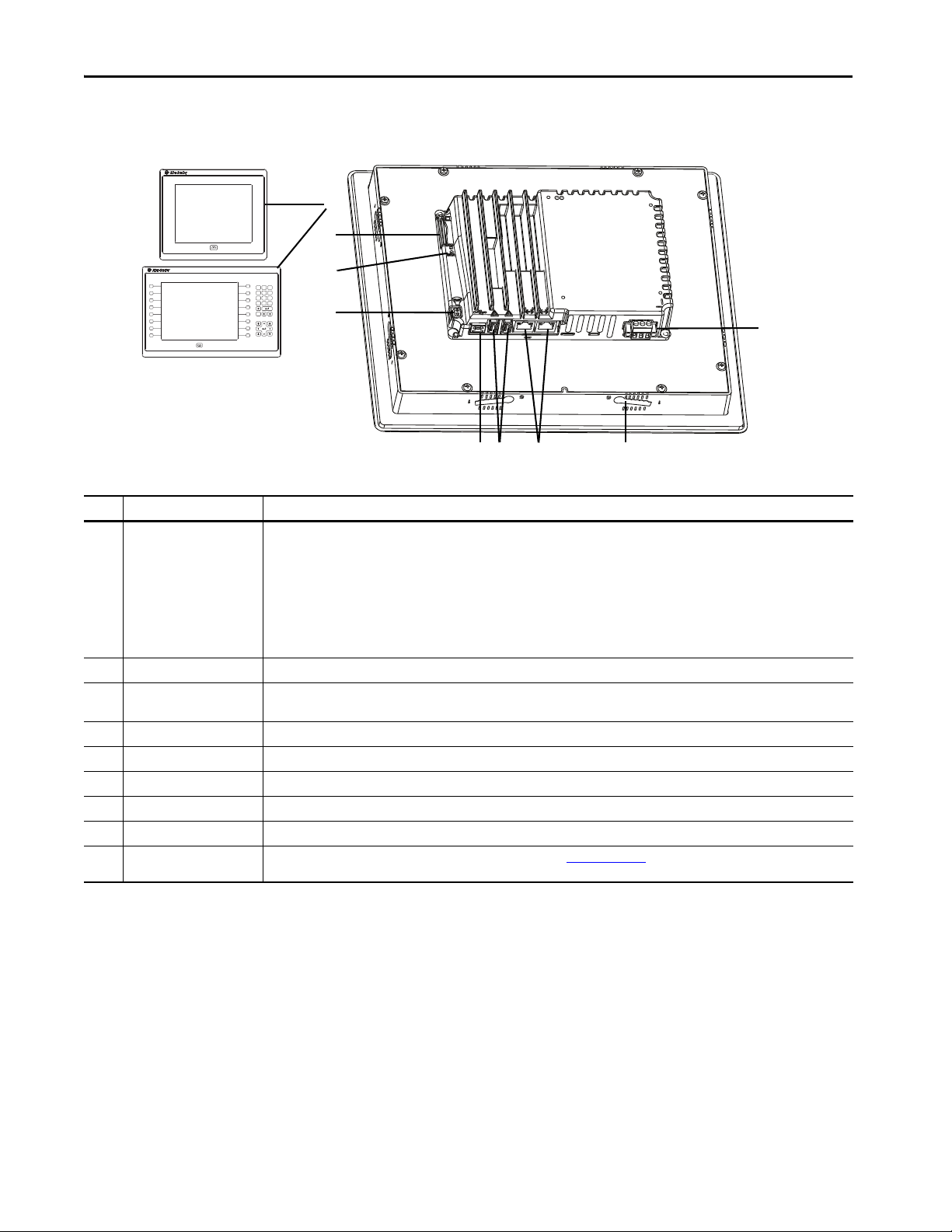
Hardware Features
The PanelView 5510 terminals are fixed hardware configurations that provide a
range of display sizes and operator input options.
Table 1 - Hardware Features
Item Feature Description
1 Display/Keypad TFT color graphic displays with a touch screen and navigation button in a range of display sizes. Some models also have a keypad and
2 Power 18…30V DC (isolated)
3 Mounting slot The slots on the top, bottom, and sides of the terminal are used with mounting levers to mount the device to a panel or enclosure. The
4 Ethernet ports Two 10/100Base-T, Auto MDI/MDI-X, EtherNet/IP ports for controller communication that supports DLR network topology.
5 USB host ports Two USB 2.0 high-speed (type A) host ports.
6 USB device port One USB 2.0 high-speed (type B) device port to connect a host computer that is software-feature dependent.
7Audio out IMPORTANT: The audio out feature is not functional. The feature is expected to be available in a future software release.
8 Status indicators Light-emitting diode indicators on back of unit provide status and fault conditions.
9 Secure Digital (SD) card slot One slot that supports an SD™ or SDHC™ card that is recommended in Table 6 on page 18
function keys providing additional operator input options.
• 6.5-in. touch or touch with keypad
• 7-in. wide screen with touch
• 9-in. wide screen with touch
• 10.4-in. touch or touch with keypad
• 12.1-in. wide screen with touch
• 15-in. touch or touch with keypad
• 19-in. touch
number of slots varies by terminal size.
.
Operator Control
All PanelView 5510 terminals have a color display with a touch screen and
navigation key, or a touch screen, navigation key, and keypad for operator control.
12 Rockwell Automation Publication 2715P-UM001D-EN-P - May 2020
• Analog, resistive, touch screens provide accurate, durable touch with
excellent reliability for control of industrial applications.
• Keypad models are similar except for the number of function keys to the
left (L#) and right (R#) of the display. Larger models have more keys.
Page 13
Overview Chapter 1
4
14
3
2
ATT EN TI ON : The keypad and touch screen support input from a finger, stylus,
and gloved hand for operation in dry or wet environments. The plastic stylus
must have a minimum tip radius of 1.3 mm (0.051 in.). Any other object or tool
can damage the keypad or touch screen.
ATT EN TI ON : Do not perform multiple operations simultaneously. Multiple
simultaneous operations can result in unintended operation.
• Touch only one operating element on the screen with one finger at one time.
• Press only one key on the terminal at one time.
L8
The physical keypad on the PanelView 5510 terminal is used during runtime to
initiate actions, control navigation, and enter data. The terminal also supports a
virtual keyboard and numeric keypad that opens on PanelView 5510 terminal
screens during runtime.
The terminal also supports the use of a physical keyboard and mouse when
connected to the USB ports.
Table 2 - PanelView 5510 Terminal Keypad
Item Feature Description
1 Navigation button Opens the navigation menu at the bottom of a screen and displays the contents of a project. The menu allows screen navigation and device
2 Numeric keypad Contains numeric, decimal, minus, and these keys:
3 Navigation keys Provides navigation control.
4Function keys
• 6.5-in. terminal
• 10.4-in. terminal
• 15-in. terminal
configuration.
• Backspace - deletes the character to the left of the insertion point.
• Enter - inputs the currently highlighted key or enters a blank line if the insertion point is in the text box of the virtual keyboard.
• Tab-left, Tab-right - selects the previous or next control or input element.
• Esc - cancels or dismisses a dialog.
• Arrow keys - selects a key on the virtual keyboard that is above, below, left, or right of the selected key. Arrow keys also move the cursor if the
cursor is in a text box.
• Home/End - moves the insertion point to the beginning or end of a text or numeric entry field.
• Page up/Page down - goes to the next or previous pages of a list.
Performs specific commands when configured for a screen or any of its graphic elements. For example, L1 can be configured to go to another
screen.
• L1…L6 and R1…R6
• L1…L8 and R1…R8
• L1…L10 and R1…R10
Rockwell Automation Publication 2715P-UM001D-EN-P - May 2020 13
Page 14

Chapter 1 Overview
Touch Gestures
Studio 5000 Environment
The PanelView 5510 terminal supports touch gestures to interact with screen
elements during runtime. Standard touch gestures include:
• Ta p – Briefly touch the target on the HMI screen with your fingertip.
• Drag – Move your fingertip over the target on the HMI screen without
contact loss.
For a list of actions you can perform by using touch gestures, see the View
Designer help.
Use the Studio 5000 environment to create HMI applications for the PanelView
5510 terminal.
The Studio 5000 environment includes these applications:
• Vie w Designer – you can create and design a project for a specific
PanelView 5510 terminal and download the project to the terminal.
You can create an application for any PanelView 5510 terminal and reuse
that same application across the entire platform.
• Logix Designer – you can develop control logic for a CompactLogix or
ControlLogix controller and download the logic to the controller.
14 Rockwell Automation Publication 2715P-UM001D-EN-P - May 2020
Page 15
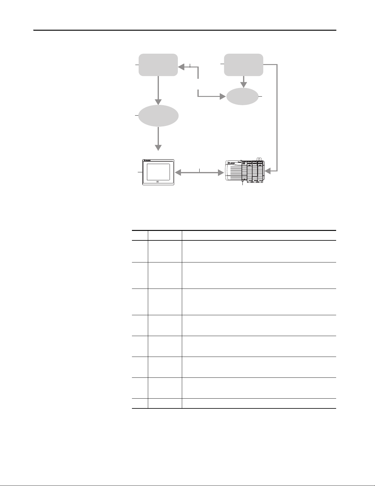
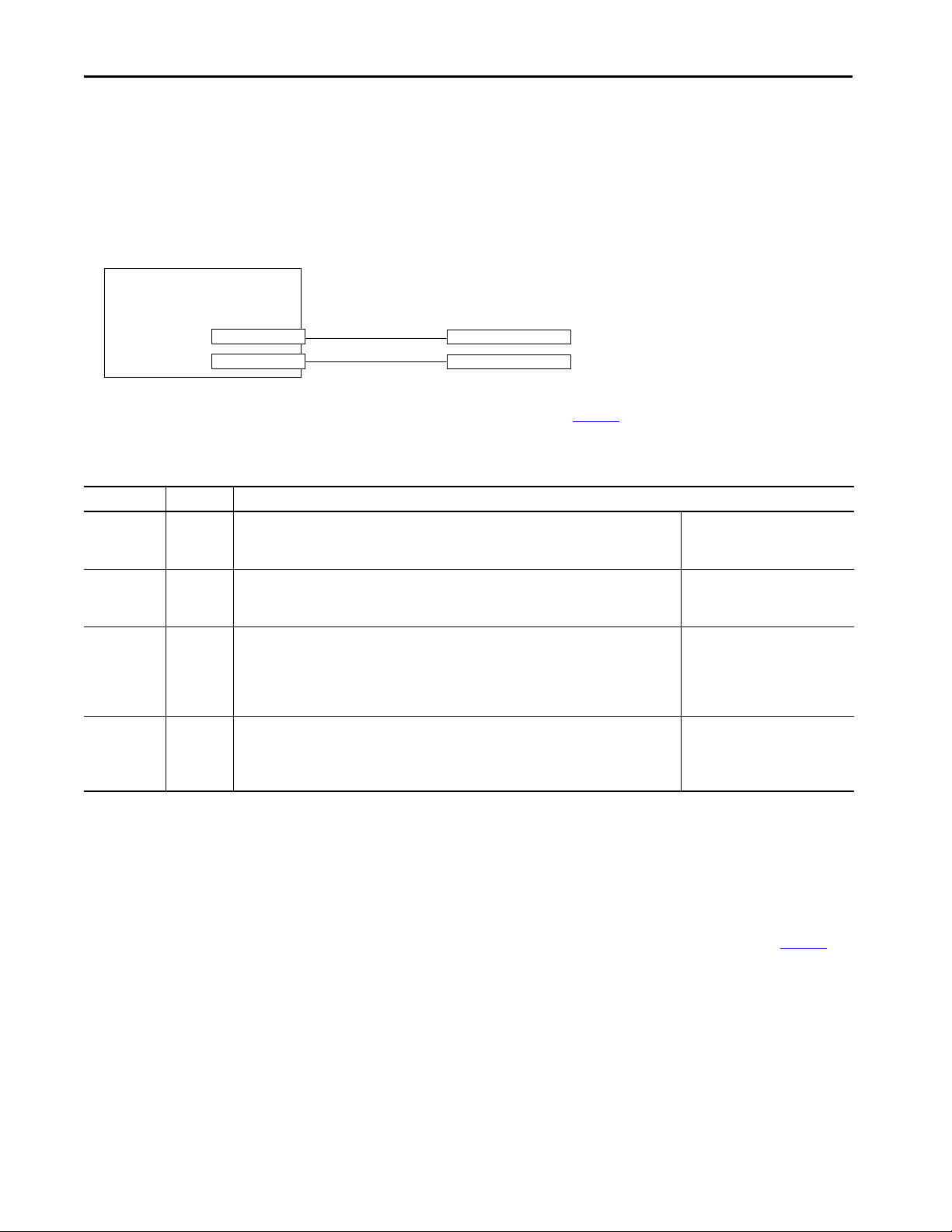
Figure 1 - How Studio 5000 Applications Work Together
1
2
3
4
5
7
6
8
View Designer
Application
Logix Designer
Application
Tag Bro wse r
Offline
ACD Fi le
HMI Project
(VPD File)
HMI Device
Control ler
Runtime
Communication
LINK NET OK
Overview Chapter 1
The table describes how the View Designer and Logix Designer applications
work together to create an HMI runtime project.
Table 3 - Studio 5000 Applications and Tools
Item Component Description
1View Designer
application
2 Tag browser A tool that is used to search for and select tags within a Studio 5000 Logix Designer ACD
3Logix Designer
application
4 ACD file An Automation Controller Database (ACD) file. An ACD file is a Logix Designer project file
5 HMI project
(VPD file)
6 HMI device A Human Machine Interface (HMI) device, such as the PanelView 5510 terminal, which
7 Runtime The environment in which the runtime HMI project communicates with the controller.
8 Controller A logic controller such as a ControlLogix or CompactLogix 5370 controller.
A Studio 5000 application that is used to build HMI projects.
Studio 5000 View Designer projects are stored as VPD files that can be downloaded to the
PanelView 5510 terminal.
project file. You can bind the tags to graphic element properties and properties of an HMI
screen. The Studio 5000 View Designer application uses the tag browser to read data from
an ACD file.
A Studio 5000 application that is used to develop control logic for an industrial
automation system. Studio 5000 Logix Designer application interfaces with controllers to
read and write tag information. Studio 5000 Logix Designer projects are stored as ACD
files that can be downloaded to the controller.
that contains the logic or code, including tags and data types, which runs within a
controller.
A View Project Database (VPD) file. A VPD project is a file that contains the operator
interface application, including HMI screens, controller references, and information about
the HMI device to run the application.
runs the HMI project. At runtime, the HMI device communicates directly with the
controller.
During runtime, the HMI device runs the downloaded project, exchanges data with the
controller, animates displayed data, and responds to operator input.
Rockwell Automation Publication 2715P-UM001D-EN-P - May 2020 15
Page 16

Chapter 1 Overview
EtherNet/IP Communication
Typical Configuration
Catalog Number Explanation
The PanelView 5510 terminals contain EtherNet/IP embedded switch
technology. These terminals communicate with ControlLogix controllers over an
Ethernet connection with DLR or linear network topologies. Star technology is
also supported when using switches.
The PanelView 5510 terminals can reside on EtherNet/IP networks that run
integrated motion and CIP Sync applications without adverse performance. The
terminal is not a consumer or producer of CIP Sync or motion packets.
Traditional DLR linear, and star network topologies are supported. See these
topics for examples:
• Device Level Ring Network Topology on page 37
• Linear Network Topology on page 38
• Star Network Topology on page 39
This table provides an explanation of the catalog numbers.
Bulletin Input Type Display Size Display Type Power – Special Option
||| |||
(1)
2715P- T = Touch 7 = 6.5-in.
B = Keypad with touch 7 = 7-in.
9 = 9-in.
10 = 10.4-in.
12 = 12.1-in.
15 = 15-in.
19 = 19-in.
(1) For the display size/display type combination, 7C designates the 6.5-in. standard display model, and 7W designates the 7-in. wide screen display model.
(2) A catalog number with -B at its end (for example, 2715P-T7WD-B) is a terminal without the Allen-Bradley® logo and product identification on the front bezel.
(3) A catalog number with -K at its end (for example, 2715P-T7CD-K) is a terminal with conformal coating.
C = Color, standard aspect ratio D = DC isolated – B = Without brand identity
(1)
W = Color, wide aspect ratio K = Conformal coating
(2)
(3)
16 Rockwell Automation Publication 2715P-UM001D-EN-P - May 2020
Page 17
Overview Chapter 1
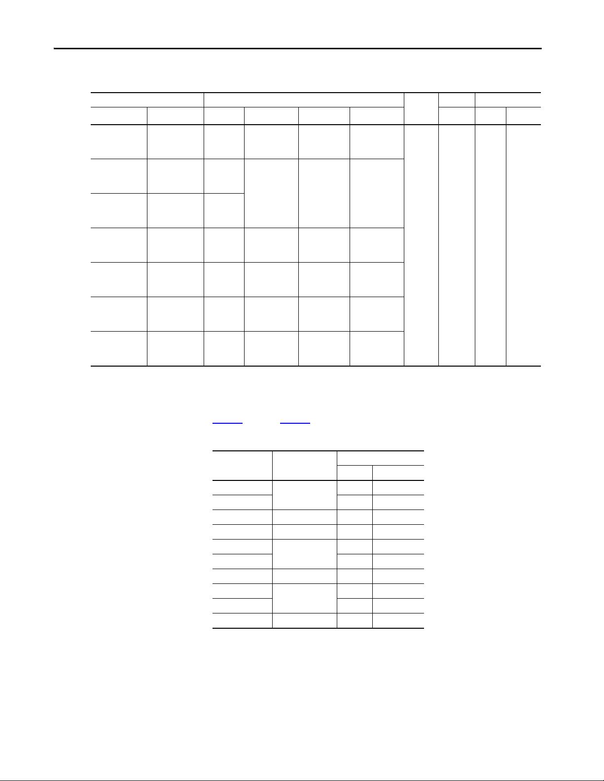
Product Selection
Cat. No. Display
Touch Key and Touch Size Type Aspect Ratio Pixels (W x H) DLR RAM User
2715P-T7CD
2715P-T7CD-B
2715P-T7CD-K
2715P-T7WD
2715P-T7WD-B
2715P-T7WD-K
2715P-T9WD
2715P-T9WD-B
2715P-T9WD-K
2715P-T10CD
2715P-T10CD-B
2715P-T10CD-K
2715P-T12WD
2715P-T12WD-B
2715P-T12WD-K
2715P-T15CD
2715P-T15CD-B
2715P-T15CD-K
2715P-T19CD
2715P-T19CD-B
2715P-T19CD-K
(1) Non-volatile memory that is available to store projects.
This table provides product selection information.
2715P-B7CD
2715P-B7CD-B
2715P-B7CD-K
— 7-in. wide WVGA TFT Color 5:3 800 x 480
— 9-in. wide
2715P-B10CD
2715P-B10CD-B
2715P-B10CD-K
— 12.1-in.
2715P-B15CD
2715P-B15CD-B
2715P-B15CD-K
— 19-in. SXGA TFT Color 5:4 1280 x 1024
6.5-in. VGA TFT Color 4:3 640 x 480 DC Yes 1 GB 1 GB
10.4-in. SVGA TFT Color 4:3 800 x 600
WXGA TFT Color 16:10 1280 x 800
wide
15-in. XGA TFT Color 4:3 1024 x 768
Input
Power
Ethernet Memory
(1)
Accessories
Ta b l e 4 through Ta b l e 8 list accessories for the PanelView 5510 terminals.
Table 4 - Protective Overlays
Operator Input
(1)
Cat. No.
2711P-RGT7SP 6.5-in. •
2711P-RGB7P •
2711P-RGT7W 7-in. wide •
2711P-RGT9SP 9-in. wide •
2711P-RGT10SP 10.4-in. •
2711P-RGB10P •
2711P-RGT12SP 12.1-in. wide •
2711P-RGT15SP 15-in. •
2711P-RGB15P •
2711P-RGT19P 19-in. •
(1) Three overlays are shipped with each catalog number.
Display Size
Tou ch Ke y and Touc h
Protective overlays help protect your PanelView terminal touch screen and keys
from scratches, dust, fingerprints, and external damage from chemicals or
abrasive materials.
Rockwell Automation Publication 2715P-UM001D-EN-P - May 2020 17
Page 18

Chapter 1 Overview
Table 5 - Power Supplies and Power Terminal Blocks
Cat. No. Description Quantity
1606-XLP95E DIN-rail power supply, 24…28V DC output voltage, 95 W 1
1606-XLP100E DIN-rail power supply, 24…28V DC output voltage, 100 W 1
2711P-RSACDIN DIN-rail power supply, AC-to-DC, 100…250V AC, 50…60 Hz 1
2711P-RTBDSP 3-pin DC power terminal block (black with white labels for +, –, and GND) 10
Table 6 - Secure Digital (SD) Cards
Cat. No. Description Quantity
1784-SD1 1-GB SD card 1
1784-SD2 2-GB SD card 1
1784-SDHC8 8-GB SDHC card 1
1784-SDHC32 32-GB SDHC card 1
2711C-RCSD USB to SD adapter for SD card 1
(1) To help reduce the chance of corruption when you use SD Cards or USB drives with the terminal, Rockwell Automation
recommends that you use only the above SD card catalog numbers.
(1)
SD and SDHC accessory cards in Ta b l e 6 have been designed to meet industrial
robustness and environmental requirements. Rockwell Automation recommends
you use these accessory cards with the terminal to help reduce the chances of
corruption. Studio 5000 View Designer software requires the following for SD
cards that are inserted into the HMI device:
• 4 GB of free space
• A supported SDHC card type, preferably one listed in Ta b l e 6
• An environmental rating for the PanelView 5000 environment
• A supported format of either FAT32 or ext3
Table 7 - Mounting Hardware
Cat. No. Description Quantity
(1)
2711P-RMCP
(1) Catalog number 2711P-RMCP mounting levers are used with the PanelView 5510 terminals. Do not use gray mounting levers; they
are not compatible with PanelView 5510 terminals.
Mounting levers (black) 16
Table 8 - Battery Replacement
Cat. No. Description Quantity
2711P-RY2032 Lithium coin cell battery, CR2032 equivalent 1
Ethernet Cables
See the Industrial Ethernet Media Brochure, publication 1585-BR001B, for
recommended Ethernet cables and media solutions.
18 Rockwell Automation Publication 2715P-UM001D-EN-P - May 2020
Page 19
Install the PanelView 5510 Terminal
Top ic Pa ge
Installation Precautions 20
North American Hazardous Locations 23
Mounting Considerations 25
Mounting Clearances 25
Panel Guidelines 26
Panel Cutout Dimensions 26
Product Dimensions 27
Prepare for Panel Mounting 28
Mount the Terminal in a Panel 31
Remove and Replace the DC Power Terminal Block 34
Connect to DC Power 35
Connect to a Network 36
Initial Startup 39
Chapter 2
ATT EN TI ON : Do not use a PanelView™ 5510 terminal for emergency stops or
other controls critical to the safety of personnel or equipment. Use separate
hard-wired operator interface devices that do not depend on solid-state
electronics.
Rockwell Automation Publication 2715P-UM001D-EN-P - May 2020 19
Page 20

Chapter 2 Install the PanelView 5510 Terminal
Installation Precautions
Read and follow these precautions before you install the PanelView 5510
terminal.
Environment and Enclosure Information
ATTENTION: This equipment is intended for use in a Pollution Degree 2
industrial environment, in overvoltage Category II applications (as defined in IEC
60664-1), at altitudes up to 2000 m (6561 ft) without derating. The terminals
are intended for use with programmable logic controllers.
This equipment is considered Group 1, Class A industrial equipment according to IEC
CISPR 11. Without appropriate precautions, there can be difficulties with
electromagnetic compatibility in residential and other environments due to
conducted or radiated disturbances.
Korean Radio Wave Suitability Registration - When so marked this
equipment is registered for Electromagnetic Conformity Registration as
business equipment (A), not home equipment. Sellers or users are
required to take caution in this regard.
이 기기는 업무용 (A 급 ) 전자파적합기기로서 판 매자 또
는 사용자는 이 점을 주의하시기 바 라 며 , 가정외의 지역
에서 사용하는 것을 목적으 로 합니다 .
This equipment is supplied as open-type equipment. It must be mounted within an
enclosure that is suitably designed for those specific environmental conditions that
can be present, and appropriately designed to help prevent personal injury
resulting from accessibility to live parts. The interior of the enclosure must be
accessible only by the use of a tool. The terminals meet specified NEMA, UL Type,
and IEC ratings only when mounted in a panel or enclosure with the equivalent
rating. Subsequent sections of this publication can contain additional information
regarding specific enclosure type ratings that are required to comply with certain
product safety certifications.
In addition to this publication, see the following:
• Industrial Automation Wiring and Grounding Guidelines, publication 1770-4.1
for additional installation requirements.
• NEMA 250 and IEC 60529, as applicable, for explanations of the degrees of
protection provided by different types of enclosure.
,
20 Rockwell Automation Publication 2715P-UM001D-EN-P - May 2020
Page 21

Wiring and Safety Guidelines
ATTENTION: Use publication NFPA 70E, Electrical Safety Requirements for
Employee Workplaces, IEC 60364 Electrical Installations in Buildings, or other
applicable wiring safety requirements for the country of installation when
wiring the devices. In addition to the NFPA guidelines, here are some other
guidelines to follow:
• Connect the device and other similar electronic equipment to its own branch
circuit.
• Protect the input power by a fuse or circuit breaker rated at no more than 15 A.
• Route incoming power to the device by a separate path from the
communication lines.
• Cross power and communication lines at right angles if they must cross.
• Communication lines can be installed in the same conduit as low-level DC I/O
lines (less than 10V).
• Shield and ground cables appropriately to avoid electromagnetic interference
(EMI). Grounding minimizes noise from EMI and is a safety measure in electrical
installations.
For more information on grounding recommendations, refer to the National
Electrical Code published by the National Fire Protection Association.
Install the PanelView 5510 Terminal Chapter 2
Outdoor Installation Recommendations
When you use a PanelView 5510 terminal outdoors, follow these
recommendations to maximize the field life of the front bezel and display:
• Do not expose terminal to direct sunlight
• Add UV protection and/or shielding
• Manage terminal temperature
• Mount terminal in an acceptable position
•Select a proper enclosure
Ultraviolet (UV) and infrared radiation can reduce the field life of any electronic
terminal. While the materials used in the terminal bezels provide long field life,
that life can be improved by proper installation and by following the suggested
guidelines.
UV radiation from the sun causes all plastics to fade or yellow and become brittle
over time. Avoid direct sunlight exposure, use a sacrificial antiglare overlay and/or
use a shield to shade the terminal to help protect the front of the terminal from
direct exposure to UV radiation and greatly increase its field life. See Ta ble 4 on
page 17 for a selection of appropriate protective overlay accessories. When you
install a sun shield that closes over the display, the temperature between the sun
shield and the display cannot exceed the maximum temperature of the display,
which is 55 °C (131 °F). Adequately ventilate all sun shields to help prevent
excess heat rise on the terminal display.
Rockwell Automation Publication 2715P-UM001D-EN-P - May 2020 21
Page 22

Chapter 2 Install the PanelView 5510 Terminal
Use stirring fans or active cooling in high altitude and high ambient temperature
locations to keep the internal enclosure temperature below 55 °C (131 °F).
Verify that the ambient temperature at which the product is operating does not
fall below its minimum rated 0 °C (32 °F).
Minimize the temperature differential between the inside of the terminal
enclosure and the front panel to help reduce the potential for condensation and
possible pressure variation between the inside and outside of the terminal.
If possible, avoid placing the terminal on the south (north in the southern
hemisphere) or west side of the cabinet, which helps reduce the heat rise due to
solar heating during the hottest part of the day.
Mount the terminal vertically to minimize solar heating on the display. Do not
mount the terminal in a sloped enclosure if it exposes the terminal to direct
sunlight. For more information, see Mounting Considerations on page 25
.
To help protect the terminal from water and dust, mount it in a proper enclosure
by following the instructions in the PanelView 5510 Terminals Product
Information, publication 2715P-PC001
. The terminals meet specified NEMA,
UL Type, and IEC ratings only when properly mounted in a panel or enclosure
with the equivalent rating. Other sections of this publication can contain
additional information about specific enclosure type ratings that are required to
comply with certain product safety certifications.
ATT EN TI ON : Failure to follow the recommended installation practices for
outdoor use can substantially reduce terminal life and void its warranty.
22 Rockwell Automation Publication 2715P-UM001D-EN-P - May 2020
Page 23
North American Hazardous Locations
Install the PanelView 5510 Terminal Chapter 2
The following information applies when operating this
equipment in hazardous locations.
ATTENTION: When marked, these products are suitable for use
in “Class I, Division 2, Groups A, B, C, D”; Class I, Zone 2, Group IIC
hazardous locations and nonhazardous locations only. Each
product is supplied with markings on the rating nameplate
indicating the hazardous location temperature code. When
combining products within a system, the most adverse
temperature code (lowest “T” number) be used to help
determine the overall temperature code of the system.
Combinations of equipment in your system are subject to
investigation by the local Authority Having Jurisdiction at the
time of installation.
WARNING: EXPLOSION HAZARD
• Do not disconnect equipment unless power has
been removed or the area is known to be
nonhazardous.
• Do not disconnect connections to this
equipment unless power has been removed or
the area is known to be nonhazardous. Secure
any external connections that mate to this
equipment by using screws, sliding latches,
threaded connectors, or other means provided
with this product.
• Substitution of components impair suitability
for Class I, Division 2.
• Peripheral equipment must be suitable for the
location in which it is used.
• The battery in this product must be changed
only in an area known to be nonhazardous.
• All wiring must be in accordance with Class I,
Division 2 wiring methods of Article 501 of the
National Electrical Code and/or in accordance
with Section 18-1J2 of the Canadian Electrical
Code, and in accordance with the authority
having jurisdiction.
Informations sur l’utilisation de cet équipement en
environnements dangereux.
ATTENTION: Les produits marqués “CL I, DIV 2, GP A, B, C, D” ne
conviennent qu'à une utilisation en environnements de Classe I
Division 2 Groupes A, B, C, D dangereux et non dangereux.
Chaque produit est livré avec des marquages sur sa plaque
d'identification qui indiquent le code de température pour les
environnements dangereux. Lorsque plusieurs produits sont
combinés dans un système, le code de température le plus
défavorable (code de température le plus faible) peut être utilisé
pour déterminer le code de température global du système. Les
combinaisons d'équipements dans le système sont sujettes à
inspection par les autorités locales qualifiées au moment de
l'installation.
AVERTISSEMENT: RISQUE D’EXPLOSION
• Couper le courant ou s'assurer que
l'environnement est classé non dangereux avant
de débrancher l'équipement.
• Couper le courant ou s'assurer que
l'environnement est classé non dangereux avant
de débrancher les connecteurs. Fixer tous les
connecteurs externes reliés à cet équipement à
l'aide de vis, loquets coulissants, connecteurs
filetés ou autres moyens fournis avec ce produit.
• La substitution de composants peut rendre cet
équipement inadapté à une utilisation en
environnement de Classe I, Division 2.
• Les équipements périphériques doivent
s'adapter à l'environnementdans lequel ils sont
utilisés.
• S'assurer que l'environnement est classé non
dangereux avant de changer la pile ou le module
horloge temps réel de ce produit.
• Tous les systèmes de câblage doivent être de
Classe I, Division 2, conformément aux méthodes
de câblage indiquées dans les Articles 501 du
National Electrical Code (Code Electrique
National) et/ou conformément à la Section 181J2 du Canadian Electrical Code (Code Electrique
Canadien), et en fonction de l'autorité de
jurisdiction.
The terminals have a temperature code of T4 when operating in a 55 °C
(131 °F) maximum ambient temperature. Do not install product in environments
where atmospheric gases have ignition temperatures less than 135 °C (275 °F).
Rockwell Automation Publication 2715P-UM001D-EN-P - May 2020 23
Page 24
Chapter 2 Install the PanelView 5510 Terminal
Nonincendive Field
Wiring Apparatus
Associated Nonincendive Field Wiring Apparatu s
PanelView 5510 Host Product
USB Peripheral Device
USB Peripheral Device
USB Host Port
USB Host Port
Required Circuit Port Parameters for USB Peripheral Devices
This product contains USB host ports that comply with hazardous location environments. Field wiring compliance
requirements are provided in compliance with the National Electrical Code, Article 500.
Figure 2 - PanelView 5510 Control Drawing
PanelView 5510 terminals provide two, separately powered USB host ports. Ta b l e 9 defines the circuit parameters of
these USB host ports.
Table 9 - Circuit Parameters for USB Host Ports
Parameter Value Parameter Definition
V
I
sc (USB)
C
a (USB)
L
a (USB)
oc (USB)
5.25V DC Open circuit voltage of each host USB port.
The maximum applied voltage rating, V
than or equal to V
1.68 A Maximum output current of each host USB port.
The maximum current, I
greater than or equal to I
10 µF This value is the maximum total capacitance that can be connected to each USB host port. The total
capacitance of each USB peripheral device and its associated cable must not exceed the indicated
value.
The maximum total capacitance, C
device shall be less that or equal to C
15 µH This value is the maximum total inductance that can be connected to each USB host port. The total
inductance of each USB peripheral de vice and its associated cable must not exceed the indicated value.
The maximum total inductance, L
device shall be less than or equal to L
oc (USB)
.
max (peripheral)
sc (USB).
max (peripheral)
, to which each USB peripheral device can be subjected, shall be
i (peripheral)
a (USB)
i (peripheral)
a (USB)
, of each USB peripheral device shall be greater
, and cable capacitance of each separate USB peripheral
.
, and cable inductance of each separate USB peripheral
.
V
max (peripheral)
(as appropriate)
I
max (peripheral)
C
L
i (peripheral)
i (peripheral)
+ C
+ L
≥ V
oc (USB)
≥ I
sc (USB)
cable(USB)
cable
≤ L
≤ C
a (USB)
a (USB)
Application Information
Per the National Electrical Code, the circuit parameters of associated field-wiring apparatus for use in hazardous
locations shall be coordinated with the host product such that their combination remains nonincendive. PanelView 5510
terminals and the USB peripheral devices shall be treated in this manner.
The USB peripheral devices and their associated cabling shall have circuit parameters with the limits given in Ta b l e 9
them to remain nonincendive when used with the PanelView 5510 USB host ports.
If cable capacitance and inductance are not known, use the following values from ANSI/ISA-RP 12.06.01-2003:
C
= 197 pF/m (60 pF/ft)
cable
L
= 0.7 µH/m (0.20 µH/ft)
cable
Nonincendive field wiring must be wired and separated in accordance with 501.10(B)(3) of the National Electrical Code
(NEC) ANSI/NFPA 70 or other local codes as applicable. This associated nonincendive field wiring apparatus has not
been evaluated for use in combination with another associated nonincendive field wiring apparatus.
24 Rockwell Automation Publication 2715P-UM001D-EN-P - May 2020
for
Page 25
Install the PanelView 5510 Terminal Chapter 2
L8
L8
L8
L8
L8
L8
Acceptable Unacceptable
0° 180°
90°
Mounting Considerations
Consider the following when mounting the terminal:
• Mount the terminal at a height suitable for operators. You can mount the
cabinet at a level other than the operator floor.
• Use appropriate light. Do not operate the terminal in direct sunlight.
• Terminals are rated to operate at various mounting positions as shown in
Figure 3
Figure 3 - Acceptable and Unacceptable Mounting Positions
.
(1)
ATT EN TI ON : Failure to follow these guidelines can result in personal injury
or damage to the panel components.
Mounting Clearances
Plan for adequate space around the terminal, inside the enclosure, for ventilation
and cables. Consider the heat from other devices in the enclosure. The ambient
temperature around the terminal must be 0…55 °C (32…131 °F)
Table 10 - Minimum Required Clearances
Terminal Area Minimum Clearance
Top 51 mm (2 in.)
Bottom 102 mm (4 in.)
Side 25 mm (1 in.)
Back 0 mm (0 in.)
(1)
.
102 mm (4 in.) is required to insert and remove an SD™ or SDHC™ card, or cable on one side
Rockwell Automation Publication 2715P-UM001D-EN-P - May 2020 25
(1) For terminals with a 15-in. or 19-in. display, the ambient temperature around the terminal must be 0…50 °C (32…122 °F) when
mounted at an angle of less than 45° or greater than 135°.
Page 26

Chapter 2 Install the PanelView 5510 Terminal
Panel Guidelines
Panel Cutout Dimensions
The terminals are panel-mounted devices that mount in the door or wall of a
NEMA, UL Type, or IP rated enclosure:
• Enclosure panels must meet the panel thickness requirements in Table 13
on page 28.
• The material strength and stiffness of the panel must be sufficient to hold
the terminal and maintain an appropriate seal against water and dust.
• The panel surface must be flat and free of imperfections to maintain an
adequate seal and NEMA, UL Type, or IP ratings.
Use the template that is shipped with your terminal to mark the cutout
dimensions.
Table 11 - PanelView 5510 - Panel Cutout Dimensions
Terminal Size Input Type Height, mm (in.) Width, mm (in.)
6.5-in. Keypad and touch 142 (5.59) 237 (9.33)
Touch 142 (5.59) 184 (7.24)
7-in. Touch 150 (5.9) 210 (8.25)
9-in. Touch 162 (6.38) 252 (9.92)
10.4-in. Keypad and touch 224 (8.82) 335 (13.19)
Touch 224 (8.82) 269 (10.59)
12.1-in. Touch 218 (8.58) 312 (12.28)
15-in. Keypad and touch 290 (11.42) 418 (16.46)
Touch 290 (11.42) 353 (13.90)
19-in. Touch 383 (15.08) 457 (17.99)
26 Rockwell Automation Publication 2715P-UM001D-EN-P - May 2020
Page 27

Install the PanelView 5510 Terminal Chapter 2
L8
A
A
D
BB
C
D
C
Product Dimensions
The table provides product dimensions. The 10.4-inch touch and combination
keypad with touch terminals are shown for illustrative purposes. All other
terminal sizes look similar.
Figure 4 - PanelView 5510 Terminal Dimensions (the 10.4-in. terminal is Shown)
Table 12 - PanelView 5510 Terminal Dimensions
Ter min al
Size Input Type
6.5-in. Keypad and touch 179 (7.05) 285 (11.22) 69.6 (2.74) 63.6 (2.50)
Touch 170 (6.69) 212 (8.35)
7-in. Touch 178 (7.0) 236 (9.3)
9-in. Touch 190 (7.48) 280 (11.02)
10.4-in. Keypad and touch 252 (9.92) 385 (15.16)
Touch 252 (9.92) 297 (11.69)
12.1-in. Touch 246 (9.69) 340 (13.39)
15-in. Keypad and touch 329 (12.95) 484 (19.06)
Touch 318 (12.52) 381 (15.00)
19-in. Touch 411 (16.18) 485 (19.09)
(1) When mounted in a panel, the front of the bezel extends less than 6.36 mm (0.25 in.) from the front of the panel.
Height
(A)
mm (in.)
Width
(B)
mm (in.)
Overall Depth
(C)
mm (in.)
Mounted Depth
(D)
mm (in.)
(1)
Rockwell Automation Publication 2715P-UM001D-EN-P - May 2020 27
Page 28
Chapter 2 Install the PanelView 5510 Terminal
6
1
1
2
3
4
5
6
Notch
Alignment Mark
Orientation of Slot Varies
Prepare for Panel Mounting
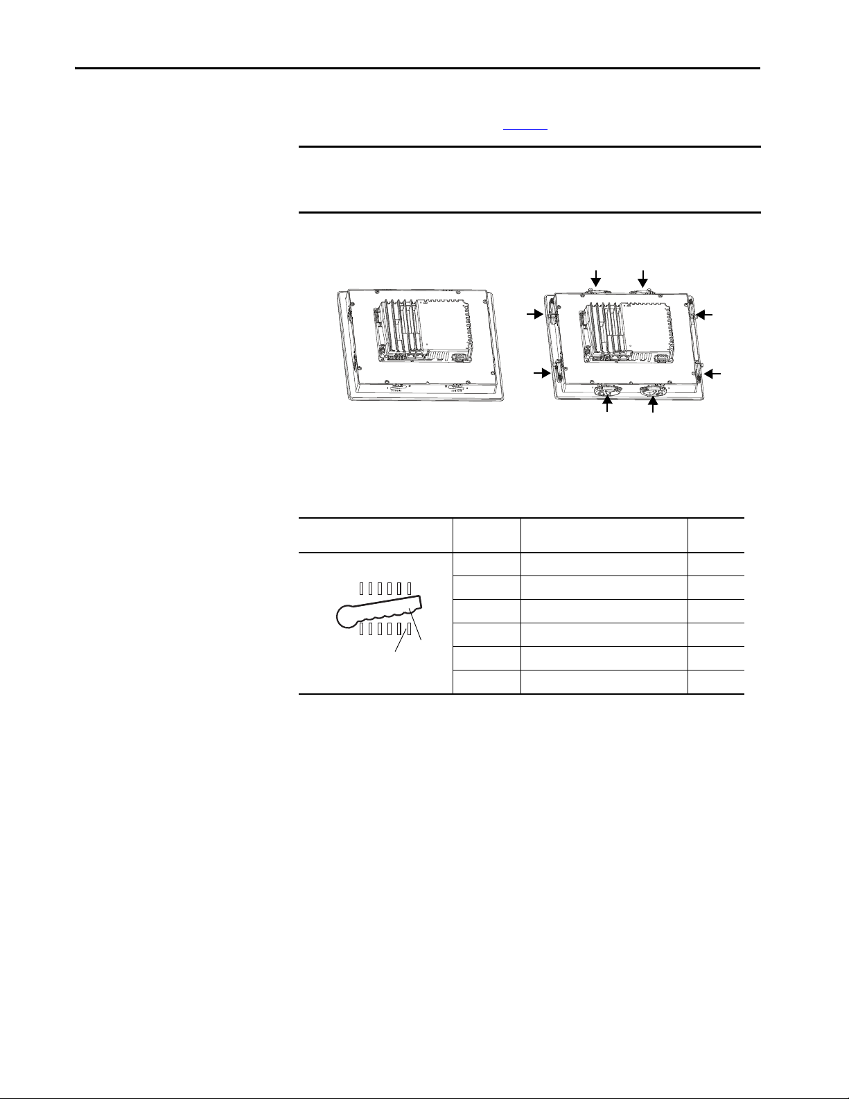
Before mounting your PanelView 5510 terminal in a panel, read this section and
the entire installation procedure on page 31
.
IMPORTANT Catalog number 2711P-RMCP mounting levers (black) are used with PanelView
5510 terminals. Do not use gray mounting levers; they are not compatible with
PanelView 5510 terminals.
Mounting levers insert into the slots around the bezel to secure the terminal in
the panel. The number of levers varies by terminal size.
Each slot has six notches with alignment marks that are locking positions for a
lever. The thickness of the panel in which you mount the terminal determines the
locking position that is required to maintain a NEMA, UL Type, or IP seal.
Table 13 - Lever Locking Positions
Mounting Slot
Lever Lock
Position
1
2
3
4
5
6
Panel Thickness Range
1.50…2.01 mm (0.060…0.079 in.) 16
2.03…2.64 mm (0.080…0.104 in.) 14
2.67…3.15 mm (0.105…0.124 in.) 12
3.17…3.66 mm (0.125…0.144 in.) 10
3.68…4.16 mm (0.145…0.164 in.) 8/9
4.19…4.80 mm (0.165…0.188 in.) 7
Typic al
Gauge
Always orient a lever vertically before inserting it into a slot. This orientation is
the only way to slide the lever knob within the slot for positioning. After sliding
the lever to a specific notch, rotate the lever toward the panel to lock it in
position. The flat side of the lever must come into contact with the panel.
28 Rockwell Automation Publication 2715P-UM001D-EN-P - May 2020
Page 29
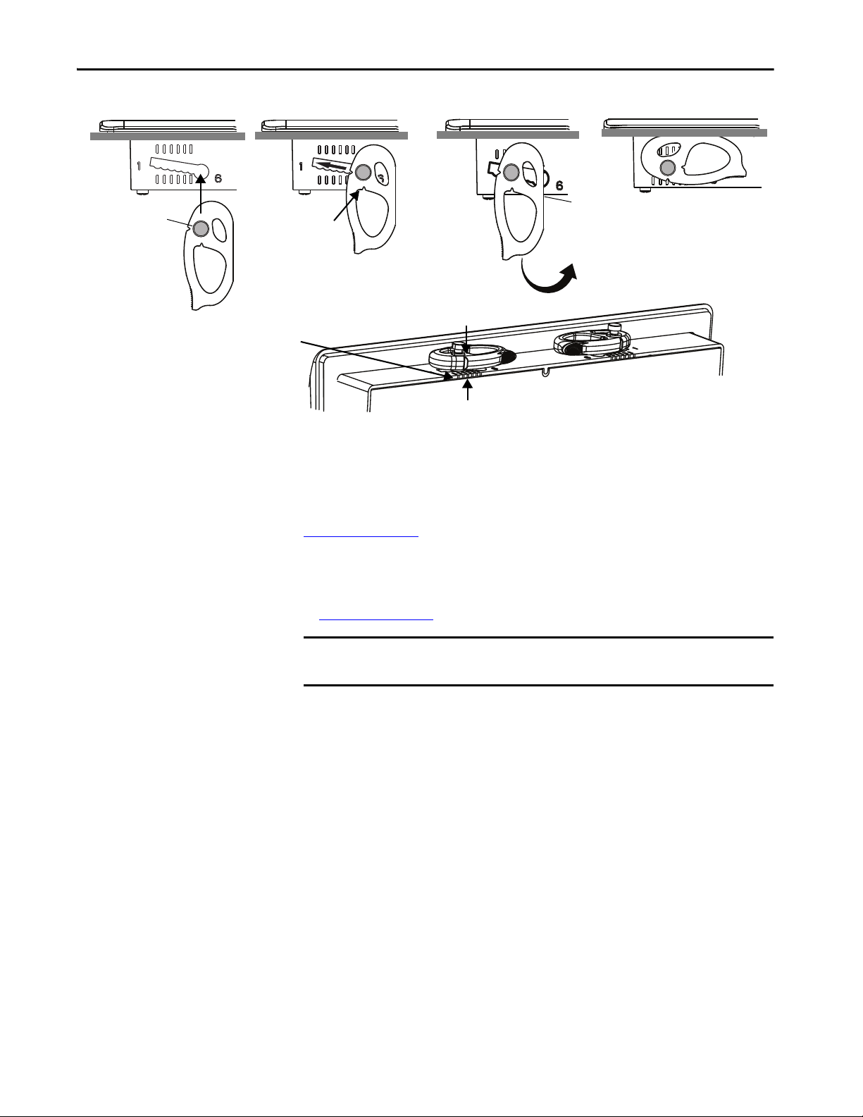
Install the PanelView 5510 Terminal Chapter 2
Flat Side
Knob on reverse
side of lever
inserts into
large end of slot
1234
The edge of the bezel has alignment indentations
to assist with the lever position.
The notch on the outside of the lever shows that
the lever is locked in position 3.
You can use an erasable marker or grease pencil to mark the
indentations for visibility of slot positions.
Inner notch on lever
shows current lever
position.
1
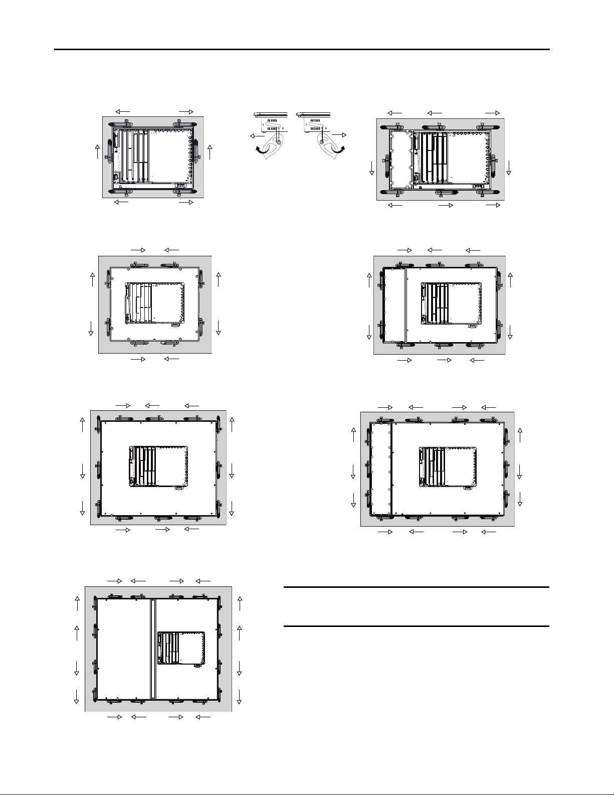
Initially, you secure the terminal in the panel by sliding each lever to a position
that is one or two notches greater than the final lock position. For example, if the
final lock position is 3, slide each lever to position 4 or 5.
Follow the locking sequence and lever orientations for each terminal as shown in
Figure 5 on page 30
.
TIP If the lock position is 6, slide lever to large end of slot or insertion hole.
You then adjust each lever to its final lock position in the same sequence as shown
in Figure 5 on page 30
.
IMPORTANT This process equalizes the pressure of the levers against the panel at a gradual
rate that reduces the probability of broken clamps.
Rockwell Automation Publication 2715P-UM001D-EN-P - May 2020 29
Page 30
Chapter 2 Install the PanelView 5510 Terminal
ERR
STS
1
212
5
24
6
6.5-in. Touch Only and 7-in. Touch Only - 6 Levers
6.5-in. Keypad and Touch - 8 Levers
2
7
4
8
8
29
3
10 1
7
5
4
5
9-in. and 10.4-in. Touch Only - 8 Levers
10.4-in. Keypad and Touch, 12.1-Touch Only - 10 Levers
3
1
6
24
5
6
8
7
3
1
6
3
1
29 4
6
12
8
11
5
82 46
11
13
9
10
14
12
15-in. Keypad and Touch - 14 Levers
53 17
1
10
3
7
15-in. Touch Only- 12 Levers
19-in. Touch Only- 16 Levers
53 1 7
82 4 6
11
13
9
15
10
16
12
14
IMPORTANT
The mounting lever orientations that are shown are required to maintain
NEMA, UL Type, and IP seals. If you require a NEMA, UL Type, or IP seal, do
not use a mounting lever in another orientation than shown.
Figure 5 - Mounting Lever Orientation and Lock Sequence
30 Rockwell Automation Publication 2715P-UM001D-EN-P - May 2020
Page 31

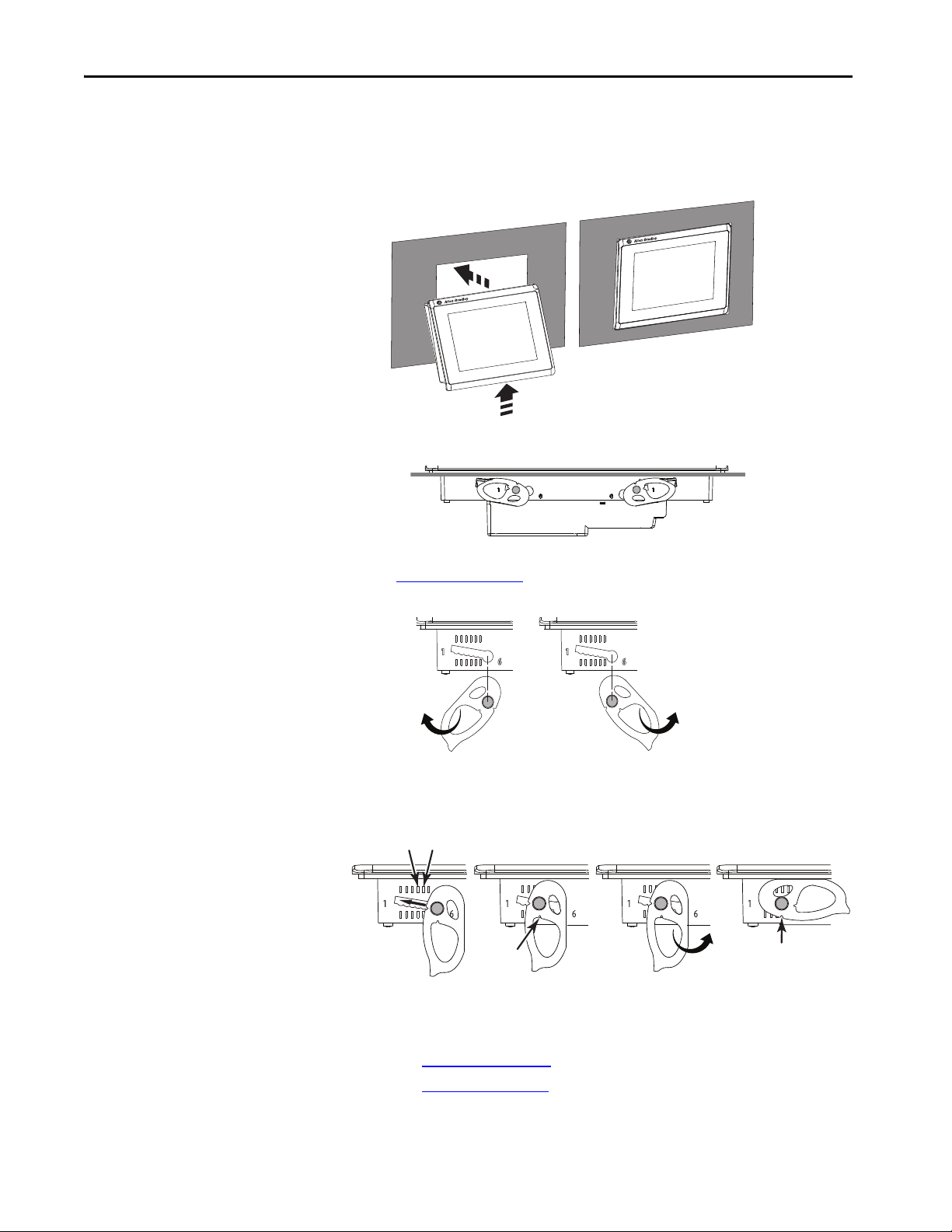
Install the PanelView 5510 Terminal Chapter 2
Gasket
Flat side
Mount the Terminal in a Panel
The PanelView 5510 terminals were designed for single-person installation. No
tools are required except for tools to make the panel cutout.
Follows these steps to mount the terminal in a panel.
ATT EN TI ON : Disconnect all electrical power from the panel before making the
panel cutout.
Make sure that the area around the panel cutout is clear and that the panel is clean
of any debris, oil, or other chemicals.
Make sure that metal cuttings do not enter any components that are already
installed in the panel and that the edges of the cutout have no burrs or sharp
edges.
Failure to follow these warnings can result in personal injury or damage to panel
components.
1. Use the cutout dimensions on page 26
2. Verify that the sealing gasket is present on the terminal.
This gasket forms a compression type seal. Do not use sealing compounds.
to cut an opening in the panel.
3. Insert and stabilize the terminal in the panel cutout.
a. Insert levers in the top corner slots in the orientation that is shown in
Figure 5 on page 30
panel.
TIP The mounting levers for PanelView 5510 terminals are black
and rotate the non-flat side of the levers toward
(catalog number 2711P-RMCP).
Do not use gray mounting levers; they are not compatible with
PanelView 5510 terminals.
Rockwell Automation Publication 2715P-UM001D-EN-P - May 2020 31
Page 32
Chapter 2 Install the PanelView 5510 Terminal
54
Inner
Notch
Outer
Notch
Flat Side
of Lever
b. Tilt the terminal toward the panel cutout and guide upward into the
cutout. Make sure that the levers stay intact.
TIP The levers help prevent the terminal from falling out of the panel.
c. Pull the top of the terminal toward you to verify that the levers are still
intact and the terminal is stabilized in the panel.
d. Insert the remaining levers in the slots by using the orientations in
Figure 5 on page 30
that are correct for your terminal.
The direction that you rotate the levers varies for each terminal size.
4. Slide and rotate each lever to a notch that is one or two positions greater
than the final lock position. Start with the first lever in the sequence.
For example, if the final lock position is 3, slide the lever to notch 4 or 5.
TIP To help position the levers and identify the final slot position, use the
alignment marks or previous marks you made on the bezel.
a. See Table 13 on page 28
b. See Figure 5 on page 30
to get the final lock position of the levers.
to get the locking sequence.
c. Rotate each lever until its flat side comes in contact with the panel.
32 Rockwell Automation Publication 2715P-UM001D-EN-P - May 2020
Page 33
Install the PanelView 5510 Terminal Chapter 2
Lever Notch
5. Adjust each lever to its final lock position shown in the same locking
sequence in Figure 5 on page 30
.
a. Unlock lever one in the sequence by rotating it away from the bezel.
b. With the lever positioned vertically to the slot, slide the lever to the
final locking position in Table 13 on page 28
.
The outer notch of the lever aligns with the bezel indentation.
c. Carefully rotate the lever back toward panel.
TIP A broken lever does not damage the product.
d. Lock the remaining levers to their final position.
6. Inspect all levers and make sure each is in the correct locked position.
ATTENTION: All levers must be in the correct and same locked position
to provide an adequate gasket seal between the terminal and the panel.
Rockwell Automation assumes no responsibility for water or chemical
damage to the terminal or other equipment within the enclosure
because of improper installation.
The notch on the outside of lever shows its locked position.
These two views show levers that are locked in position 3.
Rockwell Automation Publication 2715P-UM001D-EN-P - May 2020 33
Page 34
Chapter 2 Install the PanelView 5510 Terminal
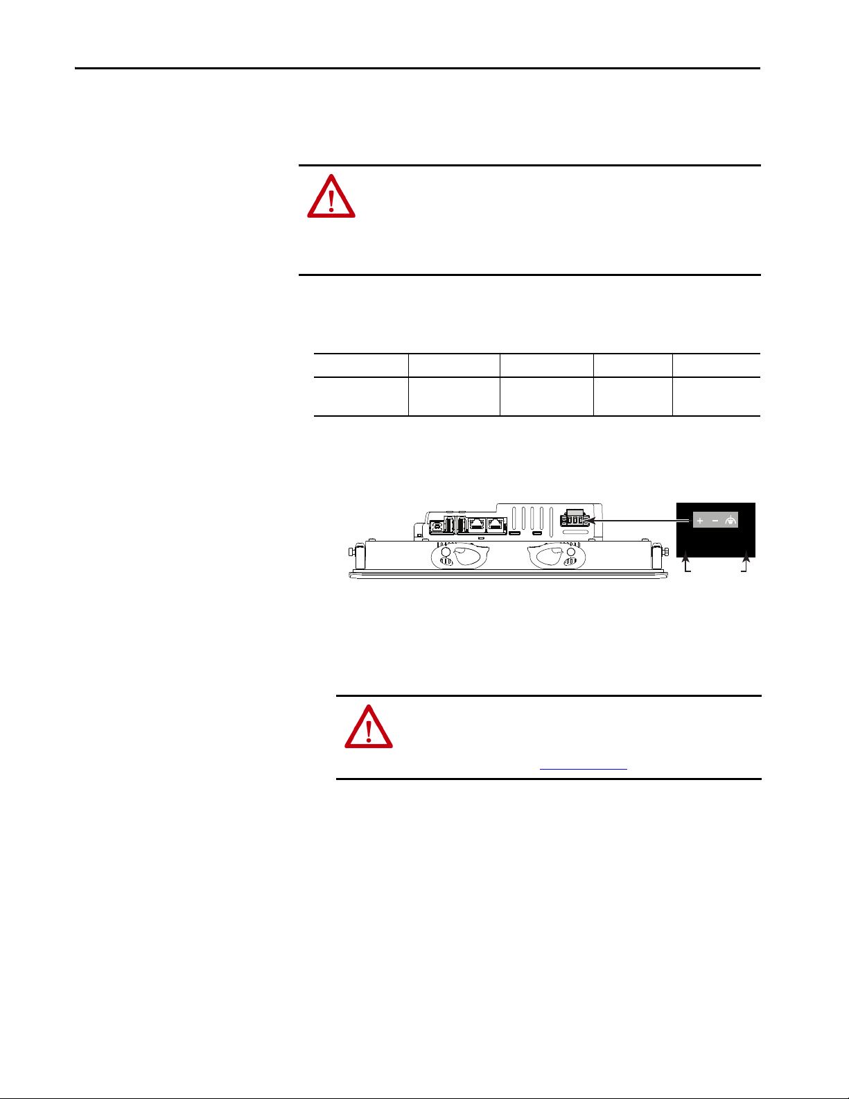
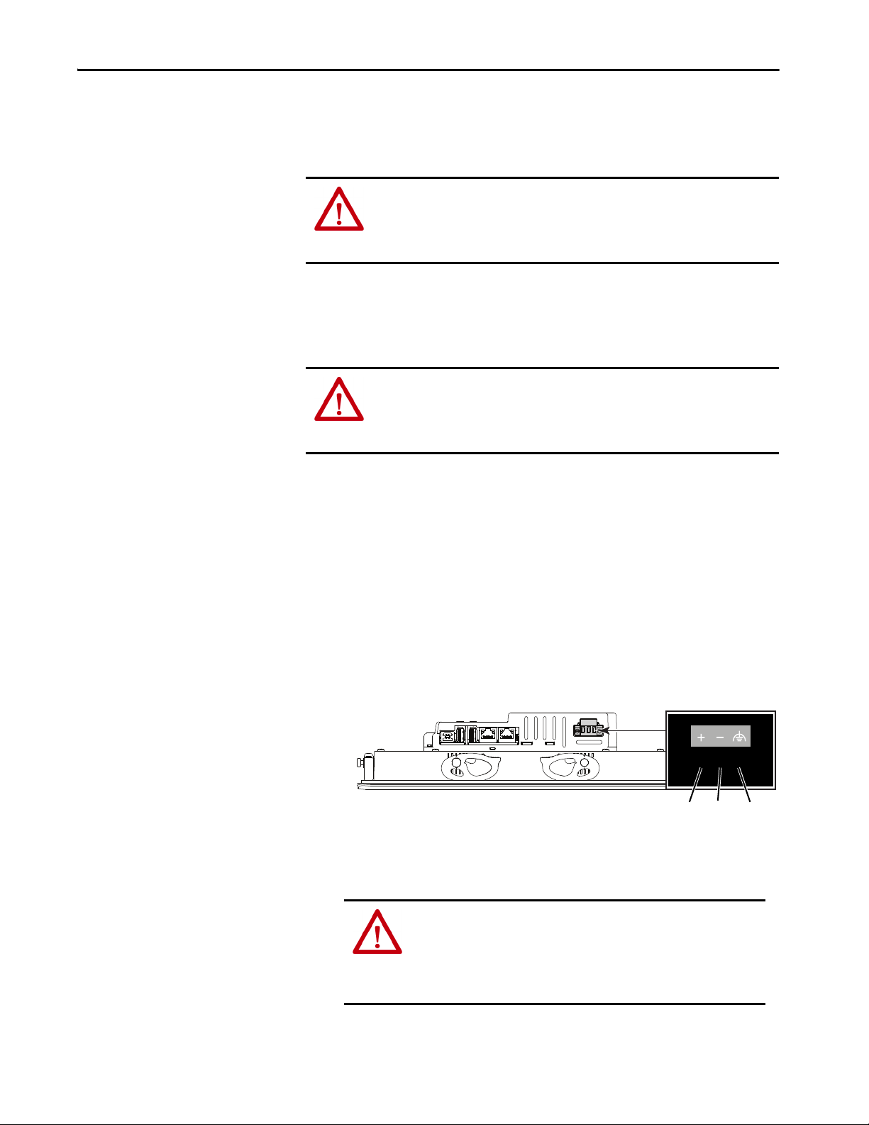
DC Terminal Block
Mounting
Screws
Remove and Replace the DC Power Terminal Block
The PanelView 5510 terminal has a 3-pin terminal block for DC power
connections. You can remove the terminal block for ease of installation, wiring,
and maintenance.
WARNING: Explosion Hazard
If you connect or disconnect wiring while the power is on, an electric arc can occur,
which can cause an explosion in hazardous location installations. Be sure that
power is removed and the area is nonhazardous before proceeding.
Failure to remove power can result in electrical shock or damage to the terminal.
Use a 0.6 x 3.5 mm screwdriver for terminal block wiring.
Table 14 - Wire Specifications for the Power Input Terminal Block
Wire Type Dual-wire Size
Stranded or solid
Cu 90 °C (194 °F)
(1) Two-wire maximum per terminal.
0.3…1.3 mm
22…16 AWG
(1)
Single-wire Size Strip Length Screw Torque
2
0.3…2.1 mm
(22…14 AWG)
2
7 mm (0.28 in.) 0.4…0.5 N•m
(3.5…4.4 lb•in)
To remove the terminal block, follow these steps.
1. Loosen the two screws that secure the DC terminal block.
1
1
2. Gently pull the terminal block away from the connector.
To install the terminal block, follow these steps.
1. Reattach the terminal block to the connector until seated.
ATTENTION: Do not use excessive force to press the terminal block into
position. The terminal blocks are keyed to fit the DC connector. If the
terminal block does not fit into the connector, verify that you have the
correct terminal block. See Table 5 on page 18
.
2. Tighten the two screws that secure the terminal block to the connector.
34 Rockwell Automation Publication 2715P-UM001D-EN-P - May 2020
Page 35
Install the PanelView 5510 Terminal Chapter 2
7 mm
20 mm
FEDC+ DC–
Connect to DC Power
Terminals with a 24V DC power supply have these power ratings:
• 24V DC nominal (18…30V DC)
• 50 W maximum (2.1 A at 24V DC)
ATT EN TI ON : The power supply is internally protected against reverse polarity.
If you connect DC+ or DC- to the earth ground terminal, you can damage the
terminal. If you connect AC power, or more than 30V DC, you can also damage
the terminal.
Terminals with a DC power input require a safety extra low voltage (SELV) or
protective extra low voltage (PELV) 24V DC power supply. Supported power
supplies include catalog numbers 1606-XLP95E, 1606-XLP100E, or
2711P-RSACDIN.
ATT EN TI ON : Use a SELV or protected extra low voltage power supply as
required by local wiring codes for your installation. The SELV and PELV power
sources provide protection so that under normal and single fault conditions, the
voltage between conductors and earth ground does not exceed a safe value.
You can power the terminal from the same power source as other equipment by
using a DC power bus.
To connect the operator terminal to a DC power source, follow these steps.
1. Verify that the wiring is not connected to a power source.
2. Strip 7 mm (0.28 in.) of insulation from the ends of the wires.
3. Secure the DC power wires to the marked terminals (+ and –) on the
terminal block.
1
1
4. Secure the functional earth (FE) ground wire to the GND terminal on the
terminal block.
Connect the GND terminal to a low-impedance FE ground.
ATTENTION: The FE ground connection to ground is mandatory. This
connection is required for noise immunity, reliability, and
Electromagnetic Compliance (EMC) with the European Union (EU)
EMC Directive for CE marking conformance. This connection is
required for safety by Underwriters Laboratory (UL).
5. Apply power to the operator terminal.
Rockwell Automation Publication 2715P-UM001D-EN-P - May 2020 35
Page 36

Chapter 2 Install the PanelView 5510 Terminal
Network Ports
Link 1Link 2
Connect to a Network
The two Ethernet ports connect to controllers on an EtherNet/IP™ network by
standard Ethernet connections. These network topologies are supported:
• Device Level Ring Network Topology
• Linear Network Topology
• Star Network Topology
Each of these EtherNet/IP network topologies supports applications that use
Integrated Motion over an EtherNet/IP network, if necessary.
IMPORTANT The terminal has dual-Ethernet ports but one device IP address.
Ethernet Ports
The Ethernet ports have two 10/100Base-T connectors for network
communication and supports MDI/MDI-X connections and DLR network
topology.
The terminal connects to an EtherNet/IP network by using a CAT5, CAT5E, or
CAT6 twisted-pair, Ethernet cable with RJ45 connectors.
IMPORTANT To help prevent accidental disconnection of the Ethernet cable:
• To minimize vibration at the connector and help reduce the chance that
personnel working inside the panel can accidentally disconnect the cable,
secure the Ethernet cable to the connector.
• Do not install the Ethernet cable too tightly. To help prevent cable pull
when the panel door is opened and closed, leave some slack in the cable.
The maximum cable length between the Ethernet ports and a 10/100Base-T port
on an Ethernet switch (without repeaters or fiber) is 100 m (328 ft).
WARNING: In hazardous locations, do not connect or disconnect any
communication cable with power that is applied to this device or any device on
the network. An electric arc can cause an explosion in hazardous location
installations. Before you proceed, make sure that the power is off or the area is
nonhazardous.
36 Rockwell Automation Publication 2715P-UM001D-EN-P - May 2020
Page 37

Install the PanelView 5510 Terminal Chapter 2
1
8
Yellow
Indicator
Green
Indicator
Table 15 - Ethernet Connector Pinout
Connector Pin Pin Name
View of RJ45
Conne ctor
1TD+
2TD-
3RD+
4Unused
5Unused
6RD-
7Unused
8Unused
Shield Connection No direct connection
(AC coupled to chassis GND)
Each Ethernet port has two indicators that provide the activity status.
Table 16 - Ethernet Status Indicators
Indicator Color Description
Link Integrity Green On when a link is present.
Activity Yellow Blinks when ac tivity is detected on Ethernet link.
Device Level Ring Network Topology
A Device Level Ring (DLR) network is a single-fault tolerant ring network that is
intended for the interconnection of automation devices. This topology is also
implemented at the device level. No additional switches are required.
TIP A DLR network contains supervisor nodes and ring nodes. The PanelView 5510
terminal operates only as a ring node on the network.
When a fault occurs, the fault location is determined and the supervisor
reconfigures the network to continue sending data on the network. Once the
fault is corrected, the supervisor reconfigures the network to operate as a normal
ring (versus a faulted ring).
For more information on DLR network topology, see EtherNet/IP Embedded
Switch Technology Application Guide, publication ENET-AP005
.
Rockwell Automation Publication 2715P-UM001D-EN-P - May 2020 37
Page 38

Chapter 2 Install the PanelView 5510 Terminal
PanelView 5510 Terminal
Conne cted Via Two DLR Ports
Computer Connected Via a 1783-ETAP EtherNet/IP Tap
ControlLogix® Controller w ith
1756-EN3TR (or EN2TR) Module
Kinetix® 350 Drive Connected Via a
1783-ETAP EtherNet/IP Tap
Kinetix 6500 Drives
with Motors
1734-AENTR POINT I/O™ Adapter
with POINT I/O Modules
1794-AENTR FLEX™ I/O Adapter
with FLEX I/O Modules
PanelView 5510 Terminal Connected
Via O ne Ethe rnet Port
Kinetix 350 Drive Connected Via a
1783-ETAP EtherNet/IP Tap
Kinetix 350 Drive Connected Via a
1783-ETAP EtherNet/IP Tap
Control Logix Control ler with
1756-EN3TR (or EN2TR) Module
1794-AENTR FLEX I/O Adapter
with FLEX I/O Modules
1734-AENTR POINT I/O Adapter
with POINT I/O Modules
Compu ter
PanelView 5510 Terminal
Using Two-port DLR option
Figure 6 - PanelView 5510 Terminal in a DLR Topology Network
Linear Network Topology
A linear network topology is a collection of devices that are daisy-chained
together across an EtherNet/IP network. Devices that can connect to a linear
network topology use embedded switch technology to eliminate the need for a
separate switch, as required in star network topologies.
Figure 7 - PanelView 5510 Terminal in a Linear Topology Network
38 Rockwell Automation Publication 2715P-UM001D-EN-P - May 2020
Page 39
Install the PanelView 5510 Terminal Chapter 2
Compu ter
Stratix 6000™ Switch
1734-AENTR POINT I/O Adapter
with POINT I/O Modules
Kinetix 350 Drive
ControlLogix Controller with
1756-EN2T Module
PanelView 5510 Terminal
Connected Via One Ethernet Port
Kinetix 350 Drive
Star Network Topology
A star network topology is a traditional EtherNet/IP network that includes
multiple devices that are connected to each other via an Ethernet switch.
Figure 8 - PanelView 5510 Terminal in a Star Topology Network
Initial Startup
IMPORTANT You must configure the Ethernet settings and update the firmware before you
can download a View Designer project and use the terminal. See Update the
Firmware Before You Use the Terminal on page 40.
If you attempt to configure the terminal settings without updating the firmware,
the Settings menu shows an update firmware message at the bottom of the screen.
Rockwell Automation Publication 2715P-UM001D-EN-P - May 2020 39
Page 40

Chapter 2 Install the PanelView 5510 Terminal
Update the Firmware Before You Use the Terminal
When power is turned on, the terminal goes through its startup sequence. The
Welcome screen displays with a Configure the Ethernet Network button.
To configure the Ethernet settings and update the firmware, follow these steps.
1. Boot up the terminal.
The Welcome dialog box displays.
2. Tap Configure the Ethernet Network.
The Internet Protocol (IP) Settings dialog box displays.
3. Configure the IP settings for the terminal.
• To obtain an IP address automatically, see Use DHCP to Assign an IP
Address For the Terminal on page 51.
• To configure IP settings manually, see Assign a Static IP Address For the
Term i na l o n pa g e 52 .
40 Rockwell Automation Publication 2715P-UM001D-EN-P - May 2020
Page 41

Install the PanelView 5510 Terminal Chapter 2
4. Tap the Ethernet icon.
5. Configure the Ethernet ports for the terminal.
See Configure the Ethernet Ports on page 54
.
6. Update the firmware by using the ControlFLASH™ software.
Begin the update at Get the Terminal Firmware on page 94
.
You can now download a View Designer application to the terminal. After the
application is downloaded, the terminal resets then automatically launches the
application.
Rockwell Automation Publication 2715P-UM001D-EN-P - May 2020 41
Page 42

Chapter 2 Install the PanelView 5510 Terminal
Notes:
42 Rockwell Automation Publication 2715P-UM001D-EN-P - May 2020
Page 43

Chapter 3
Configure Terminal Settings
Topic Page Topic Page
Runtime Environment 43 Configure the Display Screen Saver 58
Enter Data With Virtual Keyboards 45 Calibrate the Touch Screen 60
Specify Keypad or Keyboard Size 46 D isable Downloads to the Terminal 62
Log On to the Terminal 48 Change the HMI Device Name 63
Log Off of the Terminal 49 View the Firmware Revision 64
Settings Menu 49 Display Terminal Diagnostics 65
Configure the IP Address of the Terminal 51 Enable the VNC Server 66
Configure a DNS Address For the Terminal 53 Load an Application from Removable
Configure the Ethernet Ports 54 Enable the VNC Server 66
View the Network Diagnostics 55 Change the Date and Time 69
Use the Data Export Feature 56 View Information for the Configured
Media
70
Control ler
67
Runtime Environment
During runtime, the PanelView™ 5510 terminal runs HMI projects. A project is
configured and downloaded to your terminal from the View Designer
application. The project launches each time the terminal restarts.
The terminal exchanges data values with the controller, animates the displayed
data, and responds when you press keys or touch a screen or element on a screen.
During runtime, you can perform these tasks:
• Navigate screens and their graphic elements
• View and manage alarms
• View and perform operations on a trend chart
• Display error information
• Configure terminal settings and view diagnostic information
Rockwell Automation Publication 2715P-UM001D-EN-P - May 2020 43
Page 44

Chapter 3 Configure Terminal Sett ings
1568910
11
13
12
72 3 4
Here is an example of a screen in a project that is downloaded to the terminal.
Item Name Description
1 Alarm status indicator button Opens the Alarm Summary screen. A button on the screen turns red and flashes when there are active alarms that are
2 Unacked (unacknowledged)
3 Previous button Opens the previous screen in the navigation history of the terminal.
4 Next button Opens the next screen in the navigation histor y of the terminal.
5 Navigation button Displays the navigation menu at the bottom of the screen. Use the Navigation menu to display shortcuts and folder contents.
6 Log On Logs you on and off the project. The name of the logged-on user appears in the system banner.
7 Data Log status Appears only if a data log is configured for the project. Tap the icon to open the Data Log popup for status details.
8 Network status Appears only if there is an issue with network communication. Tap the icon to open the Device Configuration Network popup for
8 Controller status Appears only if there is an issue with the controller. Tap the icon to open the Controllers popup for details about the issue.
10 Time and date Displays the current time and date.
11 System banner Appears at the top of each screen in a project.
12 Project screen Displays screens, shortcuts, and popups of a project that is created in the View Designer application.
13 Navigation menu Displays menu items that you have access to when you are logged in. To display the navigation menu, press the Navigation button
number
unacknowledged. The button returns to its pictured default state with a gray icon when all alarms return to normal, even if alarms
are unacknowledged.
Displays the number of unacknowledged alarms in the project, regardless of the inhibit state of the alarms.
IMPORTANT: Using the Next button requires that a previous screen is first displayed.
IMPORTANT: The logged-on user sees only the screens for which the user has access.
details about the issue.
below the screen or in the 11system banner above the screen. You can tab to menu items to open the screens of the project. Tap a
menu item to display that project in the screen.
The navigation menu also provides access to the Settings menu for the terminal.
44 Rockwell Automation Publication 2715P-UM001D-EN-P - May 2020
Page 45

Configure Terminal Settings Chapter 3
1
3
2
10
11
4
9 76
5
8
Enter Data With Virtual Keyboards
The virtual keyboard or virtual numeric keypad opens during runtime when text
or numeric input is required.
• The virtual keyboard opens on the PanelView 5510 terminal screen when
you tap a field or element that requires text or numeric input.
• The virtual numeric keypad opens on the PanelView 5510 terminal screen
when you tap a field or element that requires only numeric input.
Figure 9 - Virtual Keyboard
Table 17 - Virtual Keyboard Description
Item Feature Description
1 Text entry field Tap the letters, numbers, and character keys to enter text into this field. The text entry
2 Clear Tap this button to remove all characters that are entered in the text entry field.
3 Backspace Tap this key to delete one charac ter to the left at a time.
4 éüç Tap this key to toggle between Roman characters and alpha-European characters.
5 Arrow keys Tap the left arrow key to move the cursor one space to the left. Tap the right arrow key
6 Cancel Tap Cancel to cancel the entry.
7 OK Tap OK to complete the entry.
8 Space bar Tap the space bar to enter a space in the text entry field.
9#?=
ABC
10 Shift Tap this key to toggle the keyboard between uppercase and lowercase letters. The
11 Caps lock Tap this key to toggle the keyboard between uppercase or lowercase letters. The
field is always active when the keyboard is open.
Numeric keys are not part of the alpha-European keyboard.
to move the cursor one space to the right.
Tap this key to toggle between symbols and alpha-numeric characters:
• When in symbol mode, the key displays as ABC.
• When in alpha-numeric mode, the key displays as #?=.
keyboard returns to lowercase characters after one character has been entered.
keyboard remains in the selected state until you tap this key again.
Rockwell Automation Publication 2715P-UM001D-EN-P - May 2020 45
Page 46

Chapter 3 Configure Terminal Sett ings
1
5
2
3
4
67
Figure 10 - Virtual Numeric Keypad
Table 18 - Virtual Numeric Keypad Description
Item Feature Description
1 Numeric entry field The numeric entry field into which you type the numeric value for the graphic
2 Min-Max value The displayed minimum and maximum values you can enter for the selected field
3 Clear Tap the X to remove all numbers that are entered into the numeric entry field.
4 Backspace Tap the backspace button to delete one number to the left at a time.
5+
–
6 Cancel Tap Cancel to cancel the entry.
7 OK Tap OK to complete the entr y.
element.
or element.
Tap the positive-negative value button to toggle between a positive or negative
number.
Specify Keypad or Keyboard Size
If you prefer to work with a larger-size keypad or keyboard, PanelView provides a
larger size option.
To specify the keypad or keyboard size, following these steps.
1. In View Designer, select Project Properties.
46 Rockwell Automation Publication 2715P-UM001D-EN-P - May 2020
2. In the Project Properties dialog box, select Application in the left panel.
Page 47

Configure Terminal Settings Chapter 3
Normal Size Keypad
Large Size Keypad
3. In the Keypad and Keyboard Size section, select either Normal or Large.
Figure 11
provides a comparison between the Normal and Large size keypad. The
larger size of both the keypad and keyboard gives you easier touch operation,
which is useful if you use gloves during equipment operation.
Figure 11 - Normal versus Large Keypad
Rockwell Automation Publication 2715P-UM001D-EN-P - May 2020 47
Page 48

Chapter 3 Configure Terminal Sett ings
Log On to the Terminal
When you log on to the terminal, the screens that you have security access to
appear as items in the navigation menu. For example, if you have been assigned
the administrator role, all screens that have administrator access appear in the
navigation menu.
TIP • The Guest user is logged on automatically at system startup. Anyone
who is not logged on to the system can view or access only those
screens assigned the level of security that is given to the Guest user
account.
• Screen security and user roles are assigned in Studio 5000 View
Designer™ and cannot be modified on the PanelView 5510 terminal.
To log on to the terminal, follow these steps.
1. In the system banner at the top of the screen, tap Log On.
The Log On dialog box opens.
2. Tap the User Name field.
The virtual keyboard opens.
3. To enter your user name with no spaces, tap the keys.
4. Tap OK .
5. Tap the Password field.
The virtual keyboard opens.
6. To enter your password with no spaces, tap the keys.
Passwords are case-sensitive.
7. Tap OK .
8. Tap Lo g On .
48 Rockwell Automation Publication 2715P-UM001D-EN-P - May 2020
Page 49

Configure Terminal Settings Chapter 3
The Log On dialog box closes and your user name appears on the Log On
button on the status banner.
TIP • You can only be logged on as one user at a time.
• If you are already logged on to the terminal, you can log on as another user.
Open the Log On dialog box, enter another user name and password, then
tap Log On.
Log Off of the Terminal
Settings Menu
When you log off, the following actions occur:
• The Guest user is logged in by default.
• If the Guest user has access to the current screen, the terminal continues to
display the current screen.
• If the Guest user does not have access to the current screen, the Home
screen for the project is displayed.
To log off the terminal, follow these steps.
1. In the status banner at the top of the screen, tap the Log On button that is
showing your user name.
The Log On dialog box opens.
2. Tap Lo g of f.
You are logged off the terminal.
You can access configuration parameters and system-wide information for the
terminal from the Navigation menu.
To open the Settings menu, follow these steps.
1. Press the navigation button on an application screen.
Rockwell Automation Publication 2715P-UM001D-EN-P - May 2020 49
Page 50

Chapter 3 Configure Terminal Sett ings
1
6
2
3
4
5
7
8
9
10
2. On the Settings screen, tab to the menu item and press Enter.
Item Menu Topic Tasks That You Can Perform
1 Network • Configure a static or dynamic device IP address
• Configure Ethernet Link 1 settings
• View network diagnostics
2 Display • Adjust the brightness of the display
• Enable or disable the screen saver
• Configure the screen saver settings
• Calibrate the touch screen
3 HMI Device • Enable or disable downloads and firmware updates
• Enter an HMI device name
• View the catalog number and current firmware revision
• View terminal diagnostic information
• Restart the terminal
4 Data Logs • Export data logs
• Remove the SD™ or SDHC™ card safely
• View data logging status
• Export alarm history
5 Troubleshooting • Select a default or impor ted profile for troubleshooting
• Save the troubleshooting log to a USB drive or SD card for Rockwell
Automation technical suppor t
6 Date and Time • Set the date and time on the terminal
• Set the time zone on the terminal
7 Controllers • View general information for the controller
• View diagnostic information for the controller
8 Load from Media • Load an application to the HMI device from removable media
9 VNC • Configure the VNC server and view the connection status
10 Email • Configure the terminal to send and receive email
50 Rockwell Automation Publication 2715P-UM001D-EN-P - May 2020
Page 51

Configure Terminal Settings Chapter 3
Configure the IP Address of the Terminal
You can configure the IP address of the terminal to use the Dynamic Host
Configuration Protocol (DHCP), or manually configure a static IP address.
A project is downloaded to the terminal from the View Designer application
through the IP address of the terminal.
TIP You cannot configure network IP addresses within the View Designer software.
Use DHCP to Assign an IP Address For the Terminal
In a DHCP configuration, the network assigns the IP address, subnet mask, and
default gateway address fields.
To configure DHCP for the terminal, follow these steps.
1. Press the navigation button on the terminal.
2. On the Settings screen, tap Network.
3. Tap the Obtain IP settings automatically using DHCP radio button.
4. To close the window, tap X.
Rockwell Automation Publication 2715P-UM001D-EN-P - May 2020 51
Page 52

Chapter 3 Configure Terminal Sett ings
Assign a Static IP Address For the Terminal
To assign a static IP address for the terminal, follow these steps.
1. Press the navigation button on the terminal.
2. On the Settings screen, tap Network.
3. Tap the Manually configure IP settings radio button.
Follow these guidelines to assign the IP Settings Configuration.
Parameter Description
IP address The range of values for the first set of numbers is 1…255.
The range of values for last three sets of numbers is 0…255
Subnet mask The subnet mask address must be identical to server subnet mask.
Gateway address Optional address.
4. Tap the IP address field.
The virtual keyboard opens.
5. To enter the IP address, use the virtual keyboard.
6. Tap OK to close the virtual keyboard.
7. Repeat steps 4
…6 for the Subnet mask and the Gateway address fields.
8. To close the window, tap X.
52 Rockwell Automation Publication 2715P-UM001D-EN-P - May 2020
Page 53

Configure Terminal Settings Chapter 3
Configure a DNS Address For the Terminal
The domain name system (DNS) translates Internet domain and host names to
IP addresses. DNS automatically converts a name that is typed in a web browser
address bar to the IP addresses of web server that host that site. You can configure
DNS addresses for common domain or host names.
TIP You cannot configure DNS addresses within the View Designer software.
To configure a DNS address for the terminal, follow these steps.
1. Press the navigation button on the terminal.
2. On the Settings screen, tap Network.
3. Tap the Manually configure IP settings radio button.
Follow these guidelines to assign the DNS settings.
Parameter Description
Primary DNS The range of values for this address is 0…255
Secondary DNS The range of values for this address is 0…255
Tertiary DNS The range of values for this address is 0…255
4. Tap the Primary DNS field.
The virtual keyboard opens.
5. To enter the DNS address, use the virtual keyboard.
6. Tap OK to close the virtual keyboard.
7. Repeat steps 4
…6 for the Secondary DNS and the Tertiary DNS fields.
8. To close the window, tap X.
Rockwell Automation Publication 2715P-UM001D-EN-P - May 2020 53
Page 54

Chapter 3 Configure Terminal Sett ings
Network Ports
Link 1Link 2
Configure the Ethernet Ports
You can configure the link speed and duplex mode for each of the Ethernet ports
on the terminal. The ports are identified as Ethernet Link 1 and Ethernet Link 2.
TIP You cannot configure the Ethernet ports within the View Designer software.
To view or change the link settings of the Ethernet ports, follow these steps.
1. Press the navigation button on the terminal.
2. On the Settings screen, tap Network.
3. Tap the Ethernet icon.
4. Select the Ethernet options for your network configuration:
• Tap the Enable Ethernet Link 1 or Enable Ethernet Link 2 check box to
add or remove the check mark. The option is enabled when the box is
checked.
IMPORTANT For DLR configurations, Ethernet Link 1 and Ethernet Link 2 must
be enabled.
• To set the speed and duplex options that are based on the network
connection, tap the Auto negotiate check box. The option is enabled
when the box is checked.
• To set the speed and duplex options, tap the Auto negotiate check box
to remove the check mark from the box. Then tap the speed and duplex
54 Rockwell Automation Publication 2715P-UM001D-EN-P - May 2020
options for your network.
5. To close the window, tap X.
Page 55

Configure Terminal Settings Chapter 3
View the Network Diagnostics
From the Network Diagnostics screen, you can view Ethernet Link 1 and
Ethernet Link 2 network connection data, network status data, and IP settings
configuration data.
To view the Network Diagnostics screen, follow these steps.
1. Press the navigation button on the terminal.
2. On the Settings screen, tap Network.
3. Tap the network diagnostic icon.
4. Tap X to close the window.
Rockwell Automation Publication 2715P-UM001D-EN-P - May 2020 55
Page 56

Chapter 3 Configure Terminal Sett ings
Use the Data Export Feature
You can export a configured data log or alarm history from the terminal to
removable media to view tag values collected on the terminal. The exported ZIP
file contains individual CSV files for each data log in the project. You can then
open the exported data log file on a personal computer to view the values in the
data log.
To export a data log or alarm history to removable media, follow these steps.
1. Insert a USB storage device or SD card into the terminal.
IMPORTANT Verify the following before you insert removable media into the
terminal:
• The format is FAT32 for the USB device or ext3 for the SD card
• The media has write permissions and sufficient space
2. Press the navigation button on an application screen.
3. On the Settings screen, tap Data Logs.
4. In the Export to file box, type a name for the export file.
Datalog is the default name.
5. Under Destination, select the media type that you inserted.
6. Tap Exp or t.
A progress bar appears to show export progress, and a data log pop-up
displays the date and time of the last exported data log.
7. If a SD card is used, verify the following before you remove the media:
a. After the data export completes and the progress bar disappears, tap
Safely Remove SD Card.
b. Verify that the Data Logger status changes from Stopped to Remove
SD card.
c. You can safely remove the SD card.
8. To close the window, tap X.
56 Rockwell Automation Publication 2715P-UM001D-EN-P - May 2020
Page 57

Configure Terminal Settings Chapter 3
Adjust the Brightness of the Display
You can adjust the brightness level of the terminal display in increments from
1…100%.
TIP Lower the brightness level to reduce the power that the backlight consumes,
and extend the life of the backlight.
These tags can also be set to control backlight brightness level:
::Local:HMIDevice.Display.BacklightIntensity
::Local:HMIDevice.Display.ScreenSaverIntensity
To adjust the brightness of the display, follow these steps.
1. Press the navigation button on the terminal.
2. On the Settings screen, tap Display.
3. Tap the Brightness field.
The virtual numeric keypad opens.
4. Enter the value for the brightness in increments from 1…100%.
5. Tap OK .
6. To close the window, tap X.
Rockwell Automation Publication 2715P-UM001D-EN-P - May 2020 57
Page 58

Chapter 3 Configure Terminal Sett ings
Modify Screen Color Settings by Using HMI Device Tags
Configure the Display Screen Saver
If you need to adjust the color of the PanelView 5000 LCD display, there are
three HMI device tags available under the Display category:
•BlueAdjustment
•GreenAdjustment
•RedAdjustment
To use these tags, bind them to Numeric Input elements you put on your custom
screen. The default value for each color is 50. To make the color more or less
pronounced, enter higher or lower values using your Numeric Inputs.
The screen saver extends the life of the back light by dimming the brightness level
when activity is not sensed for a specified amount of time. When the screen saver
is activated, the terminal displays a moving image at a reduced brightness level.
When user input is sensed, the screen saver is deactivated and the display
brightness returns to its configured level.
TIP After the screen saver is deactivated, touch or keypad input is ignored for at
least 0.5 seconds.
To configure the brightness and screen saver for the display, follow these steps.
1. Press the navigation button on the terminal.
2. On the Settings screen, tap Display.
58 Rockwell Automation Publication 2715P-UM001D-EN-P - May 2020
Page 59

Configure Terminal Settings Chapter 3
3. To add or remove the check mark next to Turn on Screen Saver, tap the
check box.
The option is enabled when the box is checked.
4. Tap the Wait field.
The virtual numeric keyboard opens.
5. Enter the number of continuous, idle minutes from 1…5999 to wait before
activating the screen saver.
The default is 10 minutes.
6. Tap OK .
7. Tap the Brightness (%) field.
The virtual numeric keyboard opens.
8. Enter the value for the brightness in increments from 1…100%.
9. Tap OK .
10. To close the window, tap X.
Rockwell Automation Publication 2715P-UM001D-EN-P - May 2020 59
Page 60

Chapter 3 Configure Terminal Sett ings
Calibrate the Touch Screen
The touch screen is calibrated at the factory. After installation, you can
recalibrate the touch screen to compensate for parallax if the screen is viewed at
an angle.
The calibration process requires you to touch a series of targets on the screen.
IMPORTANT For accuracy and to prevent damage to the touch screen, use a plastic stylus
device with a minimum tip radius of 1.3 mm (0.051 in.).
To calibrate the touch screen, follow these steps.
1. Press the navigation button on the terminal.
2. On the Settings screen, tap Display.
3. Tap Ca li brate To uc h.
A red target appears on the screen.
4. Press and hold the center of the target until the target completes the circle.
The next target appears.
TIP Touch inside the target areas before the progress indicator completes
a circle.
5. Continue to press and hold the centers of all remaining targets as they
appear.
All processed targets are replaced with white targets.
60 Rockwell Automation Publication 2715P-UM001D-EN-P - May 2020
Page 61

Configure Terminal Settings Chapter 3
A green circle with a check indicates a successful calibration.
A red circle with an X indicates a failed calibration.
If the calibration fails, the process automatically repeats. Continue the
calibration until the calibration is successful.
TIP The calibration is retained after a reset or power cycle.
Rockwell Automation Publication 2715P-UM001D-EN-P - May 2020 61
Page 62

Chapter 3 Configure Terminal Sett ings
Disable Downloads to the Termina l
As a security measure, you can disable downloads to the terminal, including
application downloads and firmware updates. Disable downloads to prevent the
current application from being replaced when an application is downloaded from
the View Designer application.
To disable downloads to the terminal, follow these steps.
1. Press the navigation button on the terminal.
2. On the Settings screen, tap HMI Device.
3. Tap the Allow Downloads and Firmware Updates check box to clear the
check box.
• Downloads are not permitted when the check box is cleared.
• Downloads are permitted when the check box is checked.
4. To close the window, tap X.
While this setting is unchecked, you cannot download another application to the
terminal or update the terminal firmware.
Attempts to download an application from the View Designer application results
in an error.
62 Rockwell Automation Publication 2715P-UM001D-EN-P - May 2020
Page 63

Configure Terminal Settings Chapter 3
Change the HMI Device Name
Each terminal has a unique default HMI device name that identifies it to other
devices on the network. You can view or change this name.
To view or change the HMI device name, follow these steps.
1. Press the navigation button on the terminal.
2. On the Settings screen, tap HMI Device.
The HMI device name field shows the current name.
3. Tap the HMI device name field.
The virtual keyboard opens.
4. To enter or modify the current name, tap the virtual keyboard keys.
TIP • You can enter up to 15 characters including letters, numbers,
and hyphens.
• The first character of the terminal name must be an upper or
lowercase letter.
5. Tap OK .
6. To close the window, tap X.
Rockwell Automation Publication 2715P-UM001D-EN-P - May 2020 63
Page 64

Chapter 3 Configure Terminal Sett ings
View the Firmware Revision
You can view the current firmware revision on the terminal. You need this
information for firmware updates, or when you call technical support.
To view the firmware revision, follow these steps.
1. Press the navigation button on the terminal.
2. On the Settings screen, tap HMI Device.
View the firmware revision under Product Information.
3. To close the window, tap X.
64 Rockwell Automation Publication 2715P-UM001D-EN-P - May 2020
Page 65

Configure Terminal Settings Chapter 3
Display Terminal Diagnostics
To view the diagnostic data for the terminal, follow these steps.
1. Press the navigation button on the terminal.
2. On the Settings screen, tap HMI Device.
3. View the information under Diagnostics.
Diagnostic Parameter Description
CPU utilization The processor usage.
Total power on time The total time the terminal has been running (powered).
CPU temperature Displays the current temperature of the CPU:
Last reboot Displays the date and time for the most recent reboot of the terminal.
Last deploy D isplays the date and time of the most recent project application download.
Memory used (RAM) The total RAM memory that is in use.
Memory free (RAM) The total RAM memory that is remaining.
Memory used (Flash) The total nonvolatile memory that is in use.
Memory free (Flash) The total nonvolatile memory that is remaining.
Battery state • Normal
• Normal: 25…94 °C (77…201 °F)
• High: 100 °C (212 °F) and higher
An over-temperature condition of 105…110 °C (221…230 °F) causes a
delayed automatic system restart. The restarts continue indefinitely until the
system is cool enough to resume normal operation.
•Low
•Depleted
4. To close the window, tap X.
Rockwell Automation Publication 2715P-UM001D-EN-P - May 2020 65
Page 66

Chapter 3 Configure Terminal Sett ings
Enable the VNC Server
You can enable VNC to connect remotely to a PanelView 5510 terminal. Use the
Remote Connectivity screen to enable or disable the VNC server.
To enable or disable a VNC connection, follow these steps.
1. Press the navigation button on an application screen.
2. On the Settings screen, tap VNC.
3. Select an access:
• Disabled: Disables the VNC server
• Enabled with view-only access: You can only view content on the
HMI device
• Enabled with full-control access: You can view content and interact
with the HMI device
TIP A warning displays with full-control access that the full-control
connection is unprotected.
4. To close the window, tap X.
66 Rockwell Automation Publication 2715P-UM001D-EN-P - May 2020
Page 67

Configure Terminal Settings Chapter 3
Load an Application from Removable Media
You can load a runtime application from removable media to the HMI device.
For PanelView terminals with firmware version 6.0 or higher, if you load a
runtime application and it requires a different firmware version than the version
on the PanelView terminal, the Load from Media procedure updates the
firmware.
To load a runtime application from removable media, follow these steps.
1. Insert a USB storage device or SD card with the runtime application into
the HMI device.
IMPORTANT Verify the following before you insert removable media into the
terminal:
• The format is FAT32 for the USB device or ext3 for the SD card
• The media has write permissions and sufficient space
2. Press the navigation button on an application screen.
3. On the Settings screen, tap Load from Media.
4. Select the appropriate source.
5. From the Runtime application files panel, select the runtime application to
load.
6. The application appears in the box underneath the Runtime application
files panel.
7. Tap Ne xt.
8. Under HMI to controller path, specify the path to use to load the runtime
application:
• Keep path currently in use on HMI device: Use the controller path
currently used on the HMI device; the current HMI to controller path
appears
• Load path defined in the runtime application file: Use the controller
path configured in the runtime application on the removable media
Rockwell Automation Publication 2715P-UM001D-EN-P - May 2020 67
Page 68

Chapter 3 Configure Terminal Sett ings
Note: To allow Load from Media to install a new revision of firmware on
the PanelView 5000, copy the firmware .dmk file to the root directory of
the SD card or USB drive. The firmware major revision must match the
major revision of View Designer used to create the .vpdr project. Firmware
.dmk files are usually a part of the Studio 5000 install located at:
C:\Users\Public\Documents\Rockwell Automation\Firmware Kits.
9. Tap Lo ad.
The HMI device performs a firmware update if needed and then loads and
runs the runtime application.
The Home screen of the runtime application opens on the HMI device.
10. To close the window, tap X.
Reboot the Terminal
To reboot the terminal, follow these steps.
1. Press the navigation button on the terminal.
2. On the Settings screen, tap HMI Device.
3. Tap Re boot .
You are prompted to confirm the reboot.
4. To reboot the terminal, tap Yes.
If you tap Yes to reboot the terminal, it restarts and displays the project
that is downloaded to the terminal.
To cancel, tap No, and then tap X to close the window.
68 Rockwell Automation Publication 2715P-UM001D-EN-P - May 2020
Page 69

Configure Terminal Settings Chapter 3
Change the Date and Time
You can change the date and time that is used for terminal operations. The date
and time is displayed on the terminal screen and recorded in log files. You can also
change the time zone for the terminal.
To change the date and time that is used for terminal operations, follow these
steps.
1. Press the navigation button on the terminal.
2. On the Settings screen, tap Date and Time.
3. Change the Date and Time fields as appropriate.
a. Tap a Date or Time field.
The virtual keyboard opens.
b. Enter a value and tap OK.
Date and Time Parameters Valid Values
Date
MM/DD/YYYY
Enter the date format including the ‘/’ characters.
Time
HH:MM:SS (24-hour format)
Enter the time format including the ‘:’ characters.
Year Up to 2999
Month 1…12
Day 0…31
Hour 0…23
Minute 0…60
Second 0…60
4. Change the time zone, if desired.
a. To move up and down the list, press and drag the scroll bar (or press and
hold an arrow button).
Or tab to the list and use the arrows keys on the physical keypad of the
terminal.
b. Tap the time zone for the terminal.
The time on the terminal is adjusted to match the selected time zone.
5. To close the window, tap X.
Rockwell Automation Publication 2715P-UM001D-EN-P - May 2020 69
Page 70

Chapter 3 Configure Terminal Sett ings
View Information for the Configured Controller
You can view general information for the controller that is configured to operate
with the terminal.
To view the general information for the controller, follow these steps.
1. Press the navigation button on the terminal.
2. On the Settings screen, tap Controllers.
The general information for the controller includes these data.
Data Type Description
Reference Name The name of the controller reference that is configured in the View Designer application.
Controller Name The name of the controller that is configured in the Logix Designer application. The name
Path The communication path for the controller. The path does not appear if a controller is not
Catalog The Catalog number of the controller. The catalog number does not appear if the controller
Firmware The major and minor revision numbers for the firmware in the controller. The firmware
Tag information The synchronization state to process changes from the controller. For example, the state
Mode The operating mode of the controller. For example, the mode can be Run, Program, or
The name does not appear if a controller is not configured for the project.
does not appear if a controller is not configured for the project.
configured for the project.
is disconnected from the network.
revision numbers do not appear if the controller is disconnected from the network.
can be Synchronized, Updating, or Detecting changes. Some tag information cannot
appear if the controller tag information is not synchronized (UNINITIATED).
Fault. The mode does not appear if the controller is disconnected from the network.
70 Rockwell Automation Publication 2715P-UM001D-EN-P - May 2020
Page 71

Configure Terminal Settings Chapter 3
The diagnostic information for the controller includes the following data.
Data Type Description
Active data items The number of data items on scan for the controller.
Failed data items The number of failed data items on scan for the controller.
Number optimized blocks The numeric of optimized data blocks on scan for the controller.
Controller Responses The number of responses received from the controller.
The connection information for the controller includes the following data.
Data Type Description
HMIBC (I/O) The number of Class 1 Common Industrial Protocol (CIP) connections to the
Alarm The number of alarm CIP connections to the controller.
Data The number of Class 3 CIP connections to the controller.
controller.
3. To close the window, tap X.
Rockwell Automation Publication 2715P-UM001D-EN-P - May 2020 71
Page 72

Chapter 3 Configure Terminal Sett ings
Notes:
72 Rockwell Automation Publication 2715P-UM001D-EN-P - May 2020
Page 73

Chapter 4
Monitor and Manage Control System Alarms
Top ic Pag e
Alarm Indicator 73
Alarm Help Menu 74
View the Alarm Summary 76
Manage the Alarms 77
Alarm Detail Pane Descriptions 78
Filter the Alarms 80
Alarm Indicator
The Unacked icon in the system banner displays the number of unacknowledged
alarms for the system.
Tap to open the alarm summary and view the system alarms.
Rockwell Automation Publication 2715P-UM001D-EN-P - May 2020 73
Page 74
Chapter 4 Monitor and Manage Control System Alarms
Alarm Help Menu
To view a brief description of the alarm function keys and status counts, follow
these steps.
1. Open the Alarm Summary (page 76
) or Alarm Manager (page 77) screen.
2. Tap .
The Help window displays a brief description of the alarm function keys
and status counts.
3. Tap X to close the window.
See Tab l e 1 9
for a detailed description of the alarm function keys and alarm status
counts.
Table 19 - Alarm Function Key Descriptions
Symbol Function Key or
Message
Acknowledge Indicates that you are aware of the alarm. This button changes the state of the
Alarm Manager Opens the alarm manager screen. The alarm manager lists all alarms that are
Back Opens the previously displayed screen. When you open the alarm manager
Deselect All Deselects all alarms in the alarm table, including the alarms that are not
Details Hides or shows the details pane, which contains the details of the last selected
Disable Stops the alarm condition from being evaluated. In effect, turns off the
Description
alarm from unacknowledged to acknowledged.
configured in the system and their current states. Therefore, the alarm
manager shows alarms that are not shown in the alarm summary, and
provides additional tasks for alarms.
screen from the alarm summary screen, this button reopens the alarm
summary screen.
displayed on the current page of alarms.
alarm. The details pane appears on the bottom half of large alarm tables and
replaces the list of alarms in medium alarm tables. If no alarm is selected, the
details pane is empty.
selected alarm. You can only disable an entire alarm. You cannot disable an
individual alarm condition.
74 Rockwell Automation Publication 2715P-UM001D-EN-P - May 2020
Page 75

Monitor and Manage Control System Alarms Chapter 4
Table 19 - Alarm Function Key Descriptions (Continued)
Symbol Function Key or
Message
Enable Enables the selected alarms in the alarm manager table, which allows the
Faulted Provides a count of the alarms in a faulted state.
Help Provides a description of the help buttons and alarm status.
In Alarm, Acked
(acknowledged)
In Alarm, Unacked
(unacknowledged)
Normal, Unacked Provides a count of the alarms where the input of the alarm has returned to
Pause Stops updates to the alarm summar y table for 10 seconds, or until another
Reset Counts Resets the alarm count in the controller and the alarm count value in the
Description
alarm condition to be evaluated, which turns on the alarm. An enabled alarm
enables all conditions for that alarm. You cannot enable an individual alarm
condition.
Provides a count of the alarms in an acknowledged state.
Provides a count of the alarms in an unacknowledged state.
normal, but the alarm has not yet been acknowledged.
operation is performed on the table. While updates to the alarm summary
table are paused, alarms in the controller are still evaluated. When the table is
no longer paused, any changes to alarm states are reflected in the table and
updates resume.
details pane of the alarm manager table to zero. The reset is performed for all
conditions of the currently selected alarm.
Reset Latched Sets the se lected digital latched state of the alarm to normal if the input of the
Select All Selects all alarms in the alarm table, including the alarms that are not
Select Page Selects all alarms that are displayed on the current page of alarms.
Shelve Helps prevents the notification of new state changes to the selected alarm if
Unshelve Unshelves the selected alarm in the alarm manager table, which allows
alarm has returned to normal. A reset of a digital latched alarm acknowledges
the alarm, if it is not acknowledged.
displayed on the current page of alarms.
the alarm is acknowledged. Updates to the alarm do not appear. The alarm
remains shelved until the shelve duration from the controller expires
automatically or you unshelve the alarm manually. Updates to the alarm then
resume.
When you shelve an alarm in the alarm summary table, you shelve only the
selected alarm conditions. When you shelve an alarm in the alarm manager
table, you shelve all conditions of the alarm. From the condition list in the
details pane of the alarm manager table, you can also shelve individual alarm
conditions.
notification of new state changes to alarms. From the condition list in the
details pane of the alarm manager table, unshelve individual alarm
conditions.
Rockwell Automation Publication 2715P-UM001D-EN-P - May 2020 75
Page 76

Chapter 4 Monitor and Manage Control System Alarms
View the Alarm Summary
The alarm summary lists alarms that are in alarm or out of alarm but still
unacknowledged. It displays one alarm condition per row. Use the alarm
summary to monitor and interact with alarms.
To view the alarm summary for the control system, follow these steps.
1. Press the navigation button on the terminal.
2. Tap Alarm Summary, or tab to the menu item and press Enter.
.
3. Tap the alarm function keys to view the alarms.
See Alarm Help Menu on page 74
for a description of the keys.
4. To return to the navigation menu, tap the navigation button on the
terminal.
5. To return to the application screens, tap an application icon.
76 Rockwell Automation Publication 2715P-UM001D-EN-P - May 2020
Page 77

Monitor and Manage Control System Alarms Chapter 4
Manage the Alarms
The Alarm Manager lists all alarms that are configured in a system and their
current states.
To manage the alarms for the control system, follow these steps.
1. Press the navigation button on the terminal.
2.
3. Tap Alarm Manager, or tab to the menu item and press Enter.
.
4. Tap the alarm function keys to manage the alarms.
See Alarm Help Menu on page 74
for a description of the keys.
5. To return to the navigation menu, tap the navigation button on the
terminal.
6. To return to the application screens, tap an application icon.
Rockwell Automation Publication 2715P-UM001D-EN-P - May 2020 77
Page 78

Chapter 4 Monitor and Manage Control System Alarms
Alarm Detail Pane Descriptions
The details pane shows details for the selected alarm condition of a selected
alarm. Condition details display the selected alarm condition in the alarm
manager table.
To view the details pane for a selected alarm, follow these steps.
1. Open the Alarm Summary (page 76
) or Alarm Manager (page 77)screen.
2. Tap .
The details pane displays a list of alarm states and conditions.
Tap again to toggle off the details pane.
See Ta b l e 2 0
Table 20 - Alarm Detail Descriptions
Alarm Detail Description
Acknowledge Time The time the selected alarm was acknowledged.
Alarm Class The user-defined class that is assigned to the alarm in the Studio 5000 Logix Designer
Alarm Count The number of times the alarm condition has entered the In Alarm state.
Alarm State The state of the alarm condition:
Condition • Analog conditions include: HIHI, HI, LO, LOLO, ROC_POS, and ROC_NEG
Current Value The current tag input value that results in the alarm state.
Disabl e Time The ti me the selected alarm was disabled.
Enable Time The time the selected alarm was enabled.
for a description of the alarm details.
project.
• Normal Unacknowledged (Normal, Unacked)
• In Alarm Acknowledged (In Alarm, Acked)
• In Alarm Unacknowledged (In Alarm, Unacked)
• Normal Acknowledged (Acknowledge)
• Discrete conditions include: TRIP and TRIP_L
78 Rockwell Automation Publication 2715P-UM001D-EN-P - May 2020
Page 79

Monitor and Manage Control System Alarms Chapter 4
Table 20 - Alarm Detail Descriptions (Continued)
Alarm Detail Description
Event Category • Digital events are categorized as discrete.
Event Time The date and time the alarm event occurred.
In Alarm Time The time the selected alarm entered the In Alarm state.
Inhibit State The value that is applied to the alarm condition that inhibits the alarm at some level.
Limit Value Exceeded The condition limit that is assigned to the alarm in the Studio 5000 Logix Designer
Max Shelve Duration The maximum time the alarm can be shelved.
Message The message that is assigned to the alarm in the Studio 5000 Logix Designer project.
Name The name of the alarm. This name includes the controller name of the alarm and the
Out of Alarm Time The time the selected alarm entered the Normal or Inactive state.
Priority The urgenc y of the alarm condition:
Quality The list of reasons why the alarm is of bad quality. This field is blank in the alarm
Severity The numeric value that is mapped to the assigned priority of the alarm condition:
Shelve Duration The default time for which the selected alarm condition is shelved to prevent the
Shelve Time The time the selected alarm was shelved.
Suppres s Time The time th e selected alarm was suppressed.
Tag 1 Value The value of the associated tag parameter 1.
Tag 2 Value The value of the associated tag parameter 2.
Tag 3 Value The value of the associated tag parameter 3.
Tag 4 Value The value of the associated tag parameter 4.
Unshelve Time The time the selected alarm was unshelved. If the alarm is shelved, this time is the time
Unsuppress Time The time the selected alarm was unsuppressed.
• Analog events are categorized as level.
These states, indicated by an icon in the alarm table, include:
• Bad Quality
•
• Disabled
•
• Suppressed
•
•Shelved
These states can be combined. When an alarm has multiple inhibit states that are
applied, the icon of the highest inhibit state appears in the table.
project.
tag name. It can also include the name of the program if the tag is defined at the
program level. Therefore, the alarm name can be configured in these configurations:
::ControllerName.TagName
Or
::ControllerName\ProgramName.TagName
•Low
•Medium
•High
•Urgent
summary because the alarm summary does not show bad quality alarms.
• 1…250 (low)
• 251…500 (medium)
• 501…750 (high)
• 751…1000 (urgent)
notification of new state changes. Shelve duration is assigned to the alarm in the Studio
5000 Logix Designer project.
that the alarm is unshelved automatically when the shelve duration expires.
Rockwell Automation Publication 2715P-UM001D-EN-P - May 2020 79
Page 80

Chapter 4 Monitor and Manage Control System Alarms
Filter the Alarms
You can filter the alarms to view only the alarms in the selected alarm state.
TIP Filters are defined for the alarm summary, alarm manager, and alarm history
viewer in View Designer.
To filter the alarms, follow these steps.
1. Tap the filter pull-down arrow .
2. Tap the up or down arrows on the scroll bar to scroll through the filter
choices
3. Tap the alarm filter that you want to use.
80 Rockwell Automation Publication 2715P-UM001D-EN-P - May 2020
Page 81

Monitor and Manage Control System Alarms Chapter 4
The selected filter displays in the filter pull-down menu.
To change the filter, tap the filter pull-down menu and select another filter.
To turn off the filter, tap No Filter.
Rockwell Automation Publication 2715P-UM001D-EN-P - May 2020 81
Page 82

Chapter 4 Monitor and Manage Control System Alarms
View the Alarm History
The PanelView 5310 terminal stores up to 40,000 alarms. The Alarm History
Viewer lets you view the alarm history at runtime. You can sort columns, filter by
alarm attributes and by time, and view a details pane to see more information
about a selected alarm record. The viewer supports both tag-based and
instruction-based Logix alarms.
To view the alarm history, follow these steps:
1. On an application screen, press .
2. Tap , and press Enter
The Alarm History Viewer displays the alarm history.
3. To change the way information is presented, you can sort columns by
clicking on the column header or select filters by following the instructions
in Filter the Alarms on page 80
Export the Alarm History
82 Rockwell Automation Publication 2715P-UM001D-EN-P - May 2020
You can export the alarm history to an SD card or USB drive. The alarm history
is exported as a zipped .CSV file that can be opened and analyzed in Excel.
To export the alarm history, follow these steps:
1. Insert a USB device or an SD card into the PanelView terminal.
2. Navigate to the Settings screen.
3. Click Data Export.
4. In the Data Export dialog box, do the following:
a. Select Alarm history.
b. In the File name field, type a name for the file to be exported.
.
Page 83

Monitor and Manage Control System Alarms Chapter 4
c. Select either USB Device or SD Card.
d. Click Export.
The alarm history is saved as a .zip file containing a .csv file. The .csv file can be
opened in Excel for further analysis.
Rockwell Automation Publication 2715P-UM001D-EN-P - May 2020 83
Page 84

Chapter 4 Monitor and Manage Control System Alarms
Notes:
84 Rockwell Automation Publication 2715P-UM001D-EN-P - May 2020
Page 85

Install and Replace Components
Top ic Pag e
Accessories and Replacement Parts 85
Voltage Precautions 85
Electrostatic Discharge Precautions 86
Connect to USB Ports 86
Insert an SD Card 87
Replace the Battery 88
Install a Protective Overlay 90
Chapter 5
Accessories and Replacement Parts
Voltage Precautions
You can view a list of accessories and replacement parts in Ta b l e 4 through
Ta b l e 8
Review the specifications of a new component before you install it to verify that
it is compatible with the terminal. Record the model, serial number, and any
other pertinent information of new components for future reference.
The terminals contain line voltages. Disconnect all power to the terminal before
you install or remove components.
in Chapter 1.
IMPORTANT We recommend that you use only Allen-Bradley® approved accessories and
replacement parts.
SHOCK HAZARD: Disconnect all power to the terminal before you remove
components.
Failure to disconnect power can result in severe electrical shock to an individual or
damage to the terminal.
Rockwell Automation Publication 2715P-UM001D-EN-P - May 2020 85
Page 86
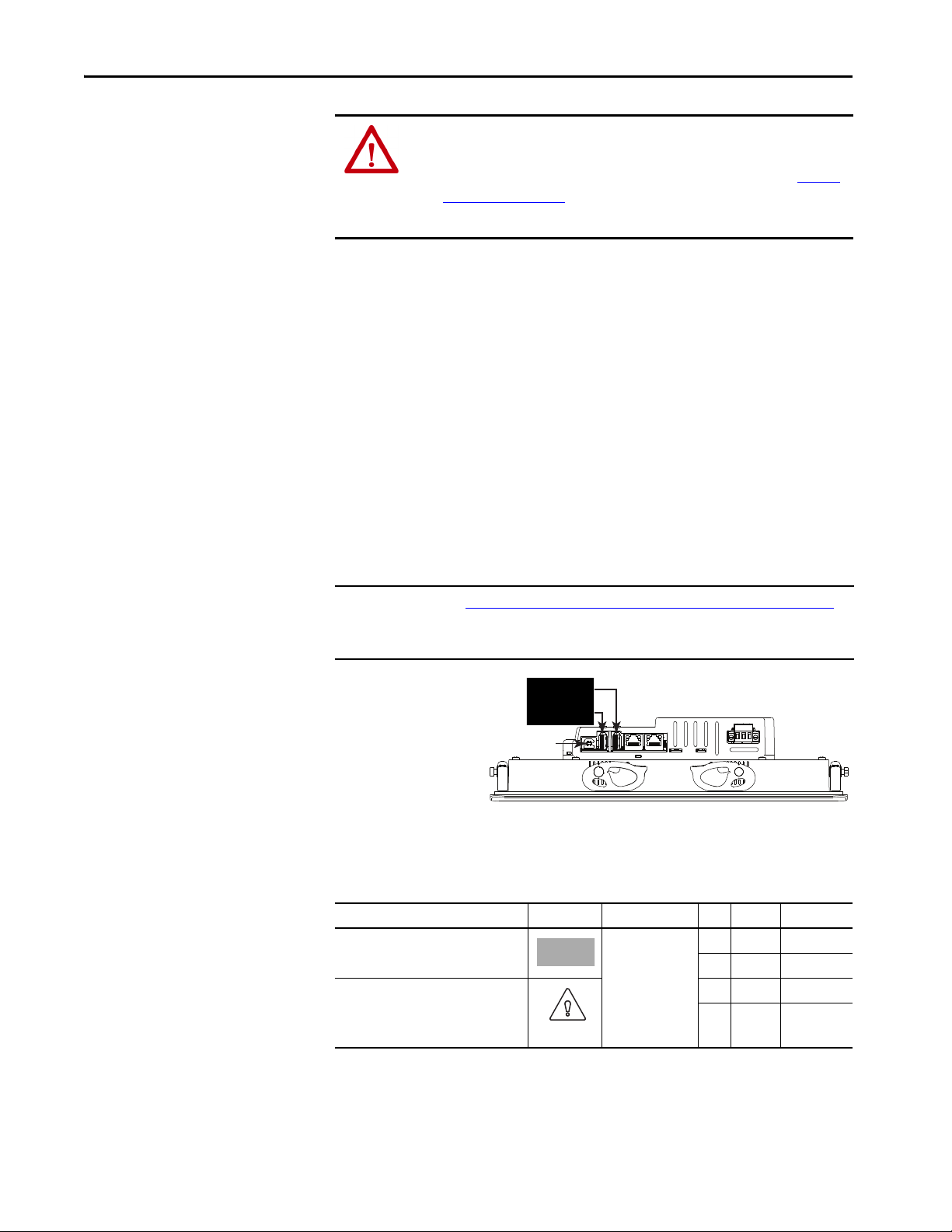
Chapter 5 Install and Replace Components
USB Host Ports
IMPORTANT: This port is not fu nctional. Do not
use this USB device port.
Electrostatic Discharge Precautions
Connect to USB Ports
ATT EN TI ON : Electrostatic discharge (ESD) can damage static-sensitive devices
or microcircuitry.
• Disconnect all power before you work on the terminal as detailed in Volt age
Precautions on page 85.
• Observe proper packaging and grounding techniques to help prevent damage.
Follow these ESD precautions when you handle this terminal:
• Touch a grounded object to discharge potential static.
• Use an anti-static wriststrap connected to the work surface.
• Use properly grounded tools and equipment.
• Avoid touching pins, leads, or circuitry.
• Always hold components with a printed circuit board (PCB) by its edges
and place it with the assembly side down.
The terminals have two USB 2.0 (type A) host ports and one USB (type B)
device port, the latter which currently is not functional. The two USB host
connections can be used with an external keyboard, external mouse, and
removable USB drives during runtime operations, and are intended for
temporary use.
IMPORTANT See Required Circuit Port Parameters for USB Peripheral Devices on page 24 for
information on the USB host ports and USB peripheral devices in hazardous
locations.
86 Rockwell Automation Publication 2715P-UM001D-EN-P - May 2020
1
1
Icons identify the USB host connections. The USB host connection supports
0.5A at 5V DC. Connected USB devices must not exceed this power load.
Table 21 - USB Connector Pinout
USB Port USB Icon USB Connector Pin Signal Description
Host (type A) 1 VCC +5V
2D- Data -
Device (type B)
IMPORTANT: This port is not functional.
The port is expected to be available in a
future s oftware rele ase.
3D+ Data +
4GND Ground
Page 87

Install and Replace Components Chapter 5
Unlocked
Locked
ATTENTION: USB devices that are not powered by the USB port must adhere to
the following:
• The USB device must be within the same enclosure as the terminal.
• The USB device must be connected to a ground system common with the
terminal or used with a USB hub that provides galvanic isolation.
• The USB device port is not for runtime operation.
Connect only externally powered USB hubs to the terminal that are USB 2.0
compatible. Before you attach devices to a USB hub, make sure that the power
adapter is connected and powered on.
USB Cables
Use only high-speed, USB 2.0 certified cables for error-free transmissions.
IMPORTANT The terminals have not been tested with USB 3.0 cables. We recommend only
the use of USB 2.0 certified cables.
Insert an SD Card
Only use a SD™ or SDHC™ card to load troubleshooting profiles and to save
troubleshooting logs. For a list of cards recommended by Rockwell Automation,
see Tab le 6 on pa ge 18
removed while the terminal is powered on and in use.
WARNING: Explosion Hazard
In hazardous location installations, if you remove or insert an SD card while the
power is on, an electric arc can occur. An electric arc can cause an explosion in
hazardous location installations. If the terminal is installed in a hazardous location,
do not remove and insert the SD card unless power has been removed or the area is
known to be nonhazardous.
The SD card slot is accessible from the inside or back of the panel when the
operator terminal is installed.
To install an SD card in the card slot, follow these steps.
1. Verify that the SD card is locked or unlocked according to your preference.
• If unlocked, the terminal can write data to or read data from the card.
• If locked, the terminal can only read data from the card.
. The SD cards are hot-swappable; they can be inserted and
Rockwell Automation Publication 2715P-UM001D-EN-P - May 2020 87
Page 88

Chapter 5 Install and Replace Components
1
6
1
6
SD Slot
ATTENTION: Orient the SD card correctly before you insert it into the slot. If
you force the card into the slot, you can damage the card or the terminal.
2. Insert the SD card firmly into the slot
until you hear a click.
When you hear the click, the card has
locked into place.
To remove the card, push the card in
slightly to unlock the SD card so you can
remove it from the slot.
Replace the Battery
The product has a lithium battery that provides back-up power for the real-time
clock. The battery can be replaced while the product is mounted in the panel.
You need a #1 Phillips screwdriver (#1 Phillips bit) to remove the logic module
and access the battery.
This product contains a sealed lithium battery, which need to be replaced during
the life of the product.
At the end of its life, the battery contained in this product should be collected
separately from any unsorted municipal waste.
The collection and recycling of batteries helps protect the environment and
contributes to the conservation of natural resources as valuable materials are
recovered.
WARNING: There is a danger of explosion if the lithium battery in this product
is incorrectly replaced. Do not replace the battery unless power has been
removed and the area is known to be nonhazardous.
Replace the battery only with catalog number 2711P-RY2032 or an equivalent
CR2032 coin-cell battery.
Do not dispose of the lithium battery in a fire or incinerator. Dispose of used
batteries in accordance with local regulations.
For safety information on the handling of lithium batteries, including handling and
disposal of leaking batteries, see Guidelines for Handling Lithium Batteries,
publication AG 5-4
.
Perchlorate material – special handling apply. See www.dtsc.ca.gov/
hazardouswaste/perchlorate.
88 Rockwell Automation Publication 2715P-UM001D-EN-P - May 2020
This perchlorate warning only applies to primary Lithium Manganese Dioxide
2
(LiMnO
) cells or batteries, and products containing these cells or batteries, sold
or distributed in California, USA.
Page 89
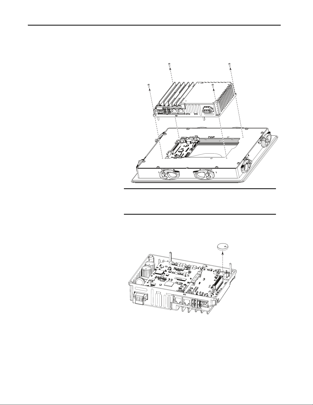
Install and Replace Components Chapter 5
Logic Module
Display Module
To replace the battery, follow these steps.
1. Disconnect power from the terminal.
2. Loosen the screws that secure the logic module to the back of the display.
SHOCK HAZARD: This equipment is sensitive to electrostatic discharge
(ESD).
Follow ESD prevention guidelines when handling this equipment.
3. Carefully lift the logic module away from the display module and turn over
to expose the circuit board.
4. Locate the coin-cell battery on the circuit board.
5. Remove the battery by lifting on the side of the battery.
6. Insert the new battery so the positive (+) polarity faces up.
Rockwell Automation Publication 2715P-UM001D-EN-P - May 2020 89
Page 90
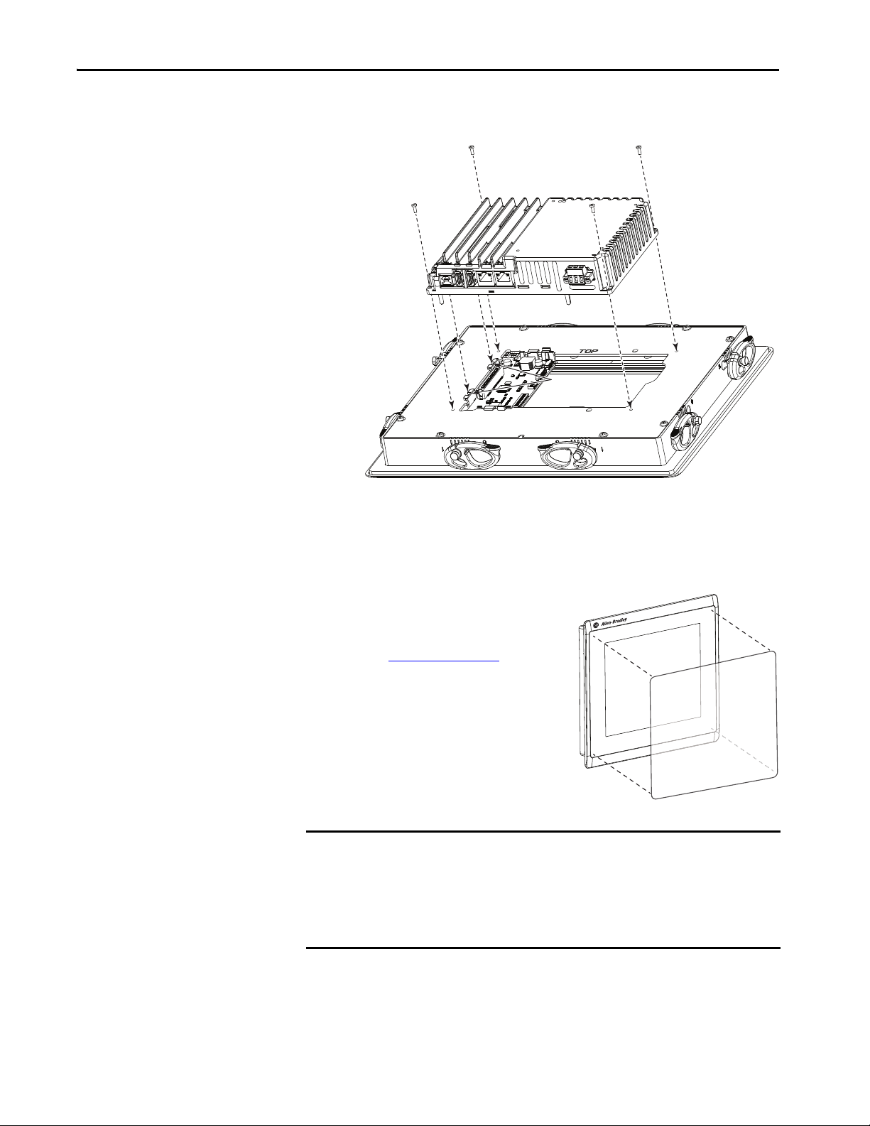
Chapter 5 Install and Replace Components
Module
Connecto rs
Logic Module
Display Module
7. Reattach the logic module by aligning the connector on the bottom of the
logic module with the connector on the back of the display module.
Install a Protective Overlay
8. Push down on the logic module and make sure that it is fully seated.
9. Tighten the screws to a torque of 0.68…0.90 N•m (6…8 lb•in).
The overlay protects the touch screen and
keys from scratches, dust, fingerprints, and
external damage from chemicals or abrasive
materials. See Tabl e 4 on pa ge 17
for a list of
available overlays.
The protective overlay covers the entire
surface of the terminal bezel inside the
aluminum perimeter. The overlay has a
protective liner that is removed by pulling
back on a tab. Do not remove the liner until
you are ready to install the overlay.
IMPORTANT Follow these guidelines when installing the overlay:
• Make sure that your hands are clean and dry.
• Handle the overlay by its edges to prevents fingerprints or lint. If you do get
marks or lint on the overlay, remove them before proceeding.
• Do not touch the adhesive ring.
Before installing the overlay, clean the touch screen and keys, if present, by using a
lint-free cloth and a mild glass cleaner. Remove all fingerprints, grease, or dust.
Marks that are not removed get trapped underneath the overlay. Grease also
90 Rockwell Automation Publication 2715P-UM001D-EN-P - May 2020
affects the adhesion of the overlay.
Page 91
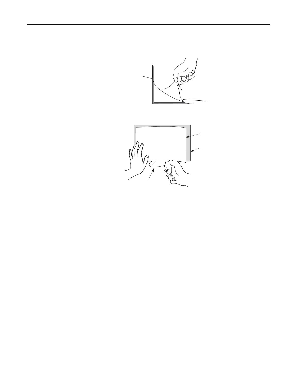
Install and Replace Components Chapter 5
Tab
Protective liner
(covers adhesive)
Overlay
Bezel
Protective Liner
To apply the protective overlay, follow these steps.
1. Pull the tab from one of the short sides and partially peel the liner away
from adhesive layer.
Hold the peeled back portion of the protective liner out of the way as you
perform the next step.
2. Center the overlay over the bezel and carefully position the adhesive
surface on the terminal.
While the protective liner is still covering the rest of the overlay, verify that
it is properly centered.
3. Slowly peel off the rest of the liner while using a soft cloth to press the
overlay on the screen.
Make sure that the overlay lies flat with no bubbles or warps.
4. With a soft cloth or finger, press around the edges of the overlay to seal it,
and remove any air bubbles trapped in the adhesive.
Clean the Overlay
Clean the overlay by using a clean, lint-free cloth, and a mild glass cleaner that
leaves no streaks. Window or eye glass cleaner is recommended. Avoid cleaners
that contain abrasives.
Remove the Overlay
Remove the overlay if it is damaged or needs replacement. Lift a corner and
slowly pull off the overlay. Use isopropyl alcohol to remove any residual adhesive.
Do not reuse the overlay.
Rockwell Automation Publication 2715P-UM001D-EN-P - May 2020 91
Page 92

Chapter 5 Install and Replace Components
Notes:
92 Rockwell Automation Publication 2715P-UM001D-EN-P - May 2020
Page 93

Update Firmware
Top ic Pag e
Before You Begin 93
Firmware Req uirements 93
Get the Terminal Firmware 94
Instal l the ControlFL ASH Software 94
Update the Firmware by Using ControlFLASH Software 95
Verify the Firmware Update 97
Chapter 6
Before You Begin
Firmware Requirements
Perform these tasks to prepare for the update:
• Verify that RSLinx® Classic is configured with an Ethernet driver to
communicate with the terminal.
• Back up your application files to a computer.
• Verify that downloads to the terminal are allowed. If downloads are
disabled, you cannot update the terminal firmware.
See Disable Downloads to the Terminal on page 62
downloads are allowed to the terminal.
• Verify the catalog number of your product and the current firmware
revision on the terminal.
See View the Firmware Revision on page 64
current firmware revision.
ControlFLASH™ software is used to update firmware in the PanelView™ 5510
terminal on the network. The update performs these actions:
•Installs updated binary files
• Preserves configuration data, such as Ethernet settings, display brightness,
time and date, and touch screen settings
to get the catalog number and
and make sure that
Rockwell Automation Publication 2715P-UM001D-EN-P - May 2020 93
Page 94

Chapter 6 Update Firmware
Use Ta b l e 2 2 to determine requirements for the firmware update.
Table 22 - Firmware Requirements for PanelView 5510 Terminals
Software Firmware Revision
Studio 5000® that also includes:
•RSLinx® Classic software
• ControlFLASH software
PanelView 5510 Terminal firmware 4.001 or later
Know the catalog number of the PanelView 5510 terminal you want to update
Know the RSLinx network path to the targeted PanelView 5510 terminal
31.00 or later
4.00.00.16 or later
14.00.10.12 or later
Get the Terminal Firmware
Install the ControlFLASH Software
Access the Rockwell Automation Product Compatibility and Downloads Center
(PCDC), at https://compatibility.rockwellautomation.com/Pages/home.aspx
.
On the home page, click Available Versions.
For instructions on how to use the PCDC site, see the Resources panel on the
PCDC home page.
ControlFLASH software is required to update firmware on the PanelView 5510
terminal. This software is included in the Studio 5000 installation package.
For details about how to install ControlFLASH software, see the
ControlFLASH firmware update Software User Manual, publication
1756-UM105
.
94 Rockwell Automation Publication 2715P-UM001D-EN-P - May 2020
Page 95

Update Firmware Chapter 6
Update the Firmware by Using ControlFLASH Software
To use the ControlFLASH software to update the firmware in a PanelView 5510
terminal, follow these steps.
1. Click Start>Programs>FLASH Programming Tools>ControlFLASH.
2. Make sure that you know the required information in the Welcome dialog
box, then click Next.
3. Select the catalog number of the PanelView 5510 terminal that you want
to update and click Next.
Rockwell Automation Publication 2715P-UM001D-EN-P - May 2020 95
Page 96

Chapter 6 Update Firmware
4. Browse to and select the device to update on the EtherNet/IP™ network
and click OK.
5. Select the firmware revision to install and click Next.
6. Read the Danger information in the Summary dialog, then click Finish.
96 Rockwell Automation Publication 2715P-UM001D-EN-P - May 2020
Page 97

Update Firmware Chapter 6
7. Click Yes to confirm that you want to update the target device.
The update starts and can take several minutes to complete.
IMPORTANT Do not cycle power to the terminal during this process or the
firmware update does not complete successfully.
When the firmware is sent to the terminal, the terminal resets and
performs diagnostics.
The Update Status dialog opens when the update is complete. If the update
was successful, the Status area is green.
8. Click OK.
If the update fails, the status area is red and reads Update failure. See the
ControlFlash firmware update Kit User Manual, publication
1756-UM105
for troubleshooting information.
Verify the Firmware Update
9. Close the ControlFLASH software.
See View Information for the Configured Controller on page 70 to view the
current firmware revision for the terminal.
Rockwell Automation Publication 2715P-UM001D-EN-P - May 2020 97
Page 98

Chapter 6 Update Firmware
Notes:
98 Rockwell Automation Publication 2715P-UM001D-EN-P - May 2020
Page 99

Troubleshooting
Top ic Pag e
Status Indicators 100
View Diagnostic Information for the Configured Controller 101
Troubleshooting Profiles 101
Terminal Does Not Start Up 105
Terminal Restarts Intermittently 105
Touch Screen Issues 105
Display Issues 106
Ethernet Issues 106
Cannot Download Application to Terminal 107
Performance Is Slow 107
Resistance to Chemicals 107
Clean the Display 108
Ship the Terminal 108
Restore Factory Defaults 109
Dispose of the Terminal 110
Chapter 7
Rockwell Automation Publication 2715P-UM001D-EN-P - May 2020 99
Page 100
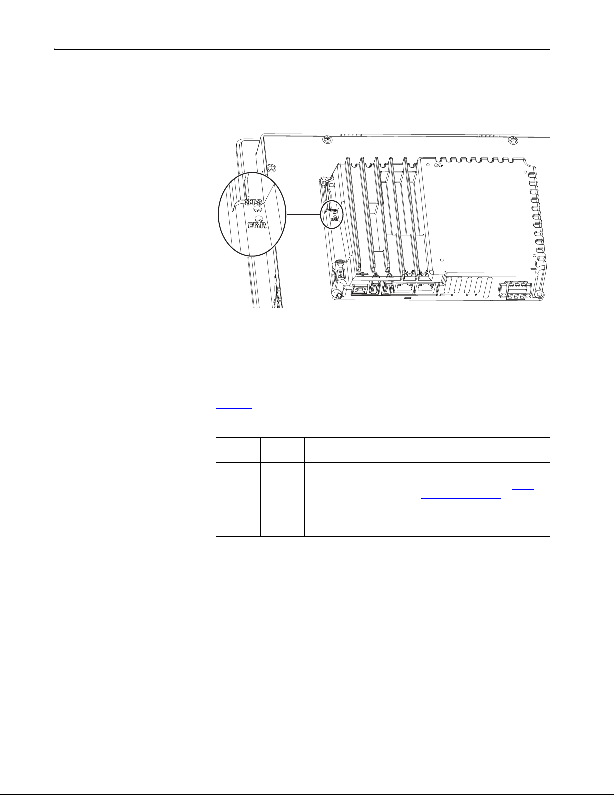
Chapter 7 Troubleshooting
Status Indicators
The back of the terminal has two indicators to identify system status:
• Status (STS) indicates that the terminal is on and in use. Its light color is
green.
• Error (ERR) indicates hardware and firmware faults. Its light color is red.
At startup, the STS and ERR indicators blink on and off, then the STS indicator
blinks to signal progress during startup. If the indicators remain off, check the
power cable.
After a successful startup, the STS indicator remains on.
Ta b l e 2 3
Table 23 - Fault Indicator States during Terminal during Startup
ERR (red)
Indicator
Blinking
On
shows indicator states if the terminal stops during startup.
STS (green)
Indicator
On Recoverable firmware error. Reload the firmware.
Off Recoverable configuration failure Restore factory defaults. Refer to Restore
On Fatal hardware error Replace t he terminal.
Blinki ng Fatal display h ardware error Rep lace the term inal.
Description Recommended Action
Factory Defaults on page 109.
100 Rockwell Automation Publication 2715P-UM001D-EN-P - May 2020
 Loading...