

Page 1

User Manual
Series K (or later)
Medium Voltage SMC™ Flex Motor Controller
Bulletin 1503E, 1560E and 1562E
Publication 1560E-UM051F-EN-P
Page 2
Important User Information
IMPORTANT
Read this document and the documents listed in the additional resources section about installation, configuration, and
operation of this equipment before you install, configure, operate, or maintain this product. Users are required to
familiarize themselves with installation and wiring instructions in addition to requirements of all applicable codes, laws,
and standards.
Activities including installation, adjustments, putting into service, use, assembly, disassembly, and maintenance are required
to be carried out by suitably trained personnel in accordance with applicable code of practice.
If this equipment is used in a manner not specified by the manufacturer, the protection provided by the equipment may be
impaired.
In no event will Rockwell Automation, Inc. be responsible or liable for indirect or consequential damages resulting from the
use or application of this equipment.
The examples and diagrams in this manual are included solely for illustrative purposes. Because of the many variables and
requirements associated with any particular installation, Rockwell Automation, Inc. cannot assume responsibility or
liability for actual use based on the examples and diagrams.
No patent liability is assumed by Rockwell Automation, Inc. with respect to use of information, circuits, equipment, or
software described in this manual.
Reproduction of the contents of this manual, in whole or in part, without written permission of Rockwell Automation,
Inc., is prohibited.
Throughout this manual, when necessary, we use notes to make you aware of safety considerations.
WARNING: Identifies information about practices or circumstances that can cause an explosion in a hazardous environment,
which may lead to personal injury or death, property damage, or economic loss.
ATTENTION: Identifies information about practices or circumstances that can lead to personal injury or death, property
damage, or economic loss. Attentions help you identify a hazard, avoid a hazard, and recognize the consequence.
Identifies information that is critical for successful application and understanding of the product.
Labels may also be on or inside the equipment to provide specific precautions.
SHOCK HAZARD: Labels may be on or inside the equipment, for example, a drive or motor, to alert people that dangerous
voltage may be present.
BURN HAZARD: Labels may be on or inside the equipment, for example, a drive or motor, to alert people that surfaces may
reach dangerous temperatures.
ARC FLASH HAZARD: Labels may be on or inside the equipment, for example, a motor control center, to alert people to
potential Arc Flash. Arc Flash will cause severe injury or death. Wear proper Personal Protective Equipment (PPE). Follow ALL
Regulatory requirements for safe work practices and for Personal Protective Equipment (PPE).
Allen-Bradley, Rockwell Software, Rockwell Automation, and TechConnect are trademarks of Rockwell Automation, Inc.
Trademarks not belonging to Rockwell Automation are property of their respective companies.
Page 3

Table of Contents
Preface
Product Overview
Service Procedure . . . . . . . . . . . . . . . . . . . . . . . . . . . . . . . . . . . . . . . . . . . . . . . . . . 9
Chapter 1
Manual Objectives . . . . . . . . . . . . . . . . . . . . . . . . . . . . . . . . . . . . . . . . . . . . . . . . . 1
Documentation . . . . . . . . . . . . . . . . . . . . . . . . . . . . . . . . . . . . . . . . . . . . . . . . . . . . 1
Description. . . . . . . . . . . . . . . . . . . . . . . . . . . . . . . . . . . . . . . . . . . . . . . . . . . . . . . . 1
1503E – OEM Controller. . . . . . . . . . . . . . . . . . . . . . . . . . . . . . . . . . . . . . . 1
1560E – Retrofit Controller. . . . . . . . . . . . . . . . . . . . . . . . . . . . . . . . . . . . . 2
1562E – Combination Controller . . . . . . . . . . . . . . . . . . . . . . . . . . . . . . . 2
SMC Flex™ Control Module. . . . . . . . . . . . . . . . . . . . . . . . . . . . . . . . . . . . . 3
Starting Modes . . . . . . . . . . . . . . . . . . . . . . . . . . . . . . . . . . . . . . . . . . . . . . . . . . . . 3
Soft Start . . . . . . . . . . . . . . . . . . . . . . . . . . . . . . . . . . . . . . . . . . . . . . . . . . . . . . 3
Selectable Kickstart. . . . . . . . . . . . . . . . . . . . . . . . . . . . . . . . . . . . . . . . . . . . . 4
Current Limit Start
Dual Ramp Start . . . . . . . . . . . . . . . . . . . . . . . . . . . . . . . . . . . . . . . . . . . . . . . 5
Full Voltage Start. . . . . . . . . . . . . . . . . . . . . . . . . . . . . . . . . . . . . . . . . . . . . . . 5
Preset Slow Speed . . . . . . . . . . . . . . . . . . . . . . . . . . . . . . . . . . . . . . . . . . . . . . 6
Linear Speed Acceleration and Deceleration . . . . . . . . . . . . . . . . . . . . . . 6
Soft Stop . . . . . . . . . . . . . . . . . . . . . . . . . . . . . . . . . . . . . . . . . . . . . . . . . . . . . . 7
Protection and Diagnostics . . . . . . . . . . . . . . . . . . . . . . . . . . . . . . . . . . . . . . . . . 8
Overload . . . . . . . . . . . . . . . . . . . . . . . . . . . . . . . . . . . . . . . . . . . . . . . . . . . . . . 8
Underload . . . . . . . . . . . . . . . . . . . . . . . . . . . . . . . . . . . . . . . . . . . . . . . . . . . 10
Undervoltage . . . . . . . . . . . . . . . . . . . . . . . . . . . . . . . . . . . . . . . . . . . . . . . . 10
Overvoltage
(5)
Unbalance . . . . . . . . . . . . . . . . . . . . . . . . . . . . . . . . . . . . . . . . . . . . . . . . . . . 11
Stall Protection and Jam Detection . . . . . . . . . . . . . . . . . . . . . . . . . . . . 11
Ground Fault . . . . . . . . . . . . . . . . . . . . . . . . . . . . . . . . . . . . . . . . . . . . . . . . 12
Thermistor/PTC Protection . . . . . . . . . . . . . . . . . . . . . . . . . . . . . . . . . . 13
Open Gate. . . . . . . . . . . . . . . . . . . . . . . . . . . . . . . . . . . . . . . . . . . . . . . . . . . 14
Line Faults. . . . . . . . . . . . . . . . . . . . . . . . . . . . . . . . . . . . . . . . . . . . . . . . . . . 15
Excessive Starts/Hour . . . . . . . . . . . . . . . . . . . . . . . . . . . . . . . . . . . . . . . . 15
Overtemperature . . . . . . . . . . . . . . . . . . . . . . . . . . . . . . . . . . . . . . . . . . . . . 15
Metering . . . . . . . . . . . . . . . . . . . . . . . . . . . . . . . . . . . . . . . . . . . . . . . . . . . . . . . . 16
I/O . . . . . . . . . . . . . . . . . . . . . . . . . . . . . . . . . . . . . . . . . . . . . . . . . . . . . . . . . . . . . 16
Communication . . . . . . . . . . . . . . . . . . . . . . . . . . . . . . . . . . . . . . . . . . . . . . . . . 17
Programming . . . . . . . . . . . . . . . . . . . . . . . . . . . . . . . . . . . . . . . . . . . . . . . . . . . . 17
Status Indication. . . . . . . . . . . . . . . . . . . . . . . . . . . . . . . . . . . . . . . . . . . . . . . . . 18
Control Options . . . . . . . . . . . . . . . . . . . . . . . . . . . . . . . . . . . . . . . . . . . . . . . . . 19
Pump Control Option. . . . . . . . . . . . . . . . . . . . . . . . . . . . . . . . . . . . . . . . 19
Braking Control Options . . . . . . . . . . . . . . . . . . . . . . . . . . . . . . . . . . . . . 21
Hardware Description. . . . . . . . . . . . . . . . . . . . . . . . . . . . . . . . . . . . . . . . . . . . 21
Power Module . . . . . . . . . . . . . . . . . . . . . . . . . . . . . . . . . . . . . . . . . . . . . . . 21
Current Loop Gate Driver (CLGD) Board . . . . . . . . . . . . . . . . . . . . . 21
Interface Board. . . . . . . . . . . . . . . . . . . . . . . . . . . . . . . . . . . . . . . . . . . . . . . 22
(2)
. . . . . . . . . . . . . . . . . . . . . . . . . . . . . . . . . . . . . . . . . . 4
. . . . . . . . . . . . . . . . . . . . . . . . . . . . . . . . . . . . . . . . . . . . . . . 10
Rockwell Automation Publication 1560E-UM051F-EN-P - June 2013 3
Page 4

Table of Contents
Installation
Functional Description . . . . . . . . . . . . . . . . . . . . . . . . . . . . . . . . . . . . . . . . . . . 25
Bulletin 1562E • Basic Control – Controlled Start only. . . . . . . . . . 25
Bulletin 1562E • Basic Control – With Controlled Stop. . . . . . . . . 25
Bulletin 1562E • DPI Control – Controlled Start only . . . . . . . . . . 26
Bulletin 1562E • DPI Control – With Controlled Stop. . . . . . . . . . 26
Bulletin 1560E • Basic Control – Controlled Start only. . . . . . . . . . 27
Bulletin 1560E • Basic Control – With Controlled Stop. . . . . . . . . 28
Bulletin 1560E • DPI Control – Controlled Start only . . . . . . . . . . 28
Bulletin 1560E • DPI Control – With Controlled Stop. . . . . . . . . . 29
Chapter 2
Receiving . . . . . . . . . . . . . . . . . . . . . . . . . . . . . . . . . . . . . . . . . . . . . . . . . . . . . . . . 39
Safety and Codes . . . . . . . . . . . . . . . . . . . . . . . . . . . . . . . . . . . . . . . . . . . . . . . . . 39
Unpacking and Inspection . . . . . . . . . . . . . . . . . . . . . . . . . . . . . . . . . . . . . . . . 39
General Precautions . . . . . . . . . . . . . . . . . . . . . . . . . . . . . . . . . . . . . . . . . . . . . . 40
Transportation and Handling . . . . . . . . . . . . . . . . . . . . . . . . . . . . . . . . . . . . . 40
Installation Site . . . . . . . . . . . . . . . . . . . . . . . . . . . . . . . . . . . . . . . . . . . . . . . . . . 40
Mounting . . . . . . . . . . . . . . . . . . . . . . . . . . . . . . . . . . . . . . . . . . . . . . . . . . . . 41
Grounding Practices . . . . . . . . . . . . . . . . . . . . . . . . . . . . . . . . . . . . . . . . . . 41
Recommended Torque Values. . . . . . . . . . . . . . . . . . . . . . . . . . . . . . . . . . . . . 42
Power Connections. . . . . . . . . . . . . . . . . . . . . . . . . . . . . . . . . . . . . . . . . . . . . . . 42
Bulletin 1562E . . . . . . . . . . . . . . . . . . . . . . . . . . . . . . . . . . . . . . . . . . . . . . . 42
Bulletin 1560E . . . . . . . . . . . . . . . . . . . . . . . . . . . . . . . . . . . . . . . . . . . . . . . 43
Bulletin 1503E . . . . . . . . . . . . . . . . . . . . . . . . . . . . . . . . . . . . . . . . . . . . . . . 49
Power Wiring . . . . . . . . . . . . . . . . . . . . . . . . . . . . . . . . . . . . . . . . . . . . . . . . . . . . 49
Interlocking. . . . . . . . . . . . . . . . . . . . . . . . . . . . . . . . . . . . . . . . . . . . . . . . . . . . . . 49
Installation . . . . . . . . . . . . . . . . . . . . . . . . . . . . . . . . . . . . . . . . . . . . . . . . . . . . . . 50
Physical Location . . . . . . . . . . . . . . . . . . . . . . . . . . . . . . . . . . . . . . . . . . . . . 50
Fan . . . . . . . . . . . . . . . . . . . . . . . . . . . . . . . . . . . . . . . . . . . . . . . . . . . . . . . . . . 50
Ground Bus Bar . . . . . . . . . . . . . . . . . . . . . . . . . . . . . . . . . . . . . . . . . . . . . . 50
Power and Control Wiring . . . . . . . . . . . . . . . . . . . . . . . . . . . . . . . . . . . . 50
Control Cables . . . . . . . . . . . . . . . . . . . . . . . . . . . . . . . . . . . . . . . . . . . . . . . 51
Fiber-Optic Cables . . . . . . . . . . . . . . . . . . . . . . . . . . . . . . . . . . . . . . . . . . . 51
Power Factor Correction Capacitors . . . . . . . . . . . . . . . . . . . . . . . . . . . 51
Surge Arrestor Protection Devices . . . . . . . . . . . . . . . . . . . . . . . . . . . . . . . . . 52
Motor Overload Protection . . . . . . . . . . . . . . . . . . . . . . . . . . . . . . . . . . . . . . . 53
Two-speed Motors. . . . . . . . . . . . . . . . . . . . . . . . . . . . . . . . . . . . . . . . . . . . 53
Multi-motor Protection . . . . . . . . . . . . . . . . . . . . . . . . . . . . . . . . . . . . . . . 53
EMC Compliance . . . . . . . . . . . . . . . . . . . . . . . . . . . . . . . . . . . . . . . . . . . . . . . . 54
Enclosure . . . . . . . . . . . . . . . . . . . . . . . . . . . . . . . . . . . . . . . . . . . . . . . . . . . . 54
Wiring. . . . . . . . . . . . . . . . . . . . . . . . . . . . . . . . . . . . . . . . . . . . . . . . . . . . . . . 54
Control Power . . . . . . . . . . . . . . . . . . . . . . . . . . . . . . . . . . . . . . . . . . . . . . . . . . . 55
Control Voltage . . . . . . . . . . . . . . . . . . . . . . . . . . . . . . . . . . . . . . . . . . . . . . 55
Control Wiring . . . . . . . . . . . . . . . . . . . . . . . . . . . . . . . . . . . . . . . . . . . . . . 55
Control Terminal Designations . . . . . . . . . . . . . . . . . . . . . . . . . . . . . . . . . . . 56
4 Rockwell Automation Publication 1560E-UM051F-EN-P - June 2013
Page 5

Chapter 3
Table of Contents
Commissioning Procedure
Programming
Preliminary Setup . . . . . . . . . . . . . . . . . . . . . . . . . . . . . . . . . . . . . . . . . . . . . . . . 57
System Characteristics. . . . . . . . . . . . . . . . . . . . . . . . . . . . . . . . . . . . . . . . . . . . 58
Important Commissioning Checks . . . . . . . . . . . . . . . . . . . . . . . . . . . . . . . . 59
Preliminary Check . . . . . . . . . . . . . . . . . . . . . . . . . . . . . . . . . . . . . . . . . . . . . . . 60
Programming . . . . . . . . . . . . . . . . . . . . . . . . . . . . . . . . . . . . . . . . . . . . . . . . . . . . 60
MV SMC Flex Module . . . . . . . . . . . . . . . . . . . . . . . . . . . . . . . . . . . . . . . 60
Hi-Pot and Megger Test . . . . . . . . . . . . . . . . . . . . . . . . . . . . . . . . . . . . . . . . . . 61
Power Supply Tests . . . . . . . . . . . . . . . . . . . . . . . . . . . . . . . . . . . . . . . . . . . . . . 64
Control Function Tests. . . . . . . . . . . . . . . . . . . . . . . . . . . . . . . . . . . . . . . . . . . 67
Resistance Checks. . . . . . . . . . . . . . . . . . . . . . . . . . . . . . . . . . . . . . . . . . . . . . . . 68
Voltage Sensing Module . . . . . . . . . . . . . . . . . . . . . . . . . . . . . . . . . . . . . . . . . . 68
Start-Up . . . . . . . . . . . . . . . . . . . . . . . . . . . . . . . . . . . . . . . . . . . . . . . . . . . . . . . . 69
Chapter 4
Overview . . . . . . . . . . . . . . . . . . . . . . . . . . . . . . . . . . . . . . . . . . . . . . . . . . . . . . . . 71
Keypad Description . . . . . . . . . . . . . . . . . . . . . . . . . . . . . . . . . . . . . . . . . . . . . . 71
Programming Menu. . . . . . . . . . . . . . . . . . . . . . . . . . . . . . . . . . . . . . . . . . . . . . 71
Password . . . . . . . . . . . . . . . . . . . . . . . . . . . . . . . . . . . . . . . . . . . . . . . . . . . . . . . . 75
Parameter Management . . . . . . . . . . . . . . . . . . . . . . . . . . . . . . . . . . . . . . . . . . 76
Random Access Memory (RAM) . . . . . . . . . . . . . . . . . . . . . . . . . . . . . . 76
Read-Only Memory (ROM) . . . . . . . . . . . . . . . . . . . . . . . . . . . . . . . . . . 76
Electrically Erasable Programmable Read-Only Memory (EEPROM)
77
Using Parameter Management with DPI HIM. . . . . . . . . . . . . . . . . . 77
Parameter Modification . . . . . . . . . . . . . . . . . . . . . . . . . . . . . . . . . . . . . . . . . . 78
Soft Start . . . . . . . . . . . . . . . . . . . . . . . . . . . . . . . . . . . . . . . . . . . . . . . . . . . . . . . . 79
Current Limit Start . . . . . . . . . . . . . . . . . . . . . . . . . . . . . . . . . . . . . . . . . . . . . . 79
Dual Ramp Start . . . . . . . . . . . . . . . . . . . . . . . . . . . . . . . . . . . . . . . . . . . . . . . . . 80
Full Voltage Start . . . . . . . . . . . . . . . . . . . . . . . . . . . . . . . . . . . . . . . . . . . . . . . . 81
Linear Speed. . . . . . . . . . . . . . . . . . . . . . . . . . . . . . . . . . . . . . . . . . . . . . . . . . . . . 81
Stop Control . . . . . . . . . . . . . . . . . . . . . . . . . . . . . . . . . . . . . . . . . . . . . . . . . . . . 81
Preset Slow Speed . . . . . . . . . . . . . . . . . . . . . . . . . . . . . . . . . . . . . . . . . . . . . . . . 82
Basic Setup . . . . . . . . . . . . . . . . . . . . . . . . . . . . . . . . . . . . . . . . . . . . . . . . . . . . . . 82
Motor Protection . . . . . . . . . . . . . . . . . . . . . . . . . . . . . . . . . . . . . . . . . . . . . . . . 84
Example Settings . . . . . . . . . . . . . . . . . . . . . . . . . . . . . . . . . . . . . . . . . . . . . . . . . 85
Undervoltage . . . . . . . . . . . . . . . . . . . . . . . . . . . . . . . . . . . . . . . . . . . . . . . . 85
Overvoltage
Jam. . . . . . . . . . . . . . . . . . . . . . . . . . . . . . . . . . . . . . . . . . . . . . . . . . . . . . . . . . 85
Underload
Motor Information. . . . . . . . . . . . . . . . . . . . . . . . . . . . . . . . . . . . . . . . . . . . . . . 86
Motor Data Entry . . . . . . . . . . . . . . . . . . . . . . . . . . . . . . . . . . . . . . . . . . . . 86
(1)
. . . . . . . . . . . . . . . . . . . . . . . . . . . . . . . . . . . . . . . . . . . . . . . 85
(2)
. . . . . . . . . . . . . . . . . . . . . . . . . . . . . . . . . . . . . . . . . . . . . . . . . 85
Metering
Chapter 5
Overview . . . . . . . . . . . . . . . . . . . . . . . . . . . . . . . . . . . . . . . . . . . . . . . . . . . . . . . . 87
Viewing Metering Data. . . . . . . . . . . . . . . . . . . . . . . . . . . . . . . . . . . . . . . . . . . 87
Rockwell Automation Publication 1560E-UM051F-EN-P - June 2013 5
Page 6

Table of Contents
Chapter 6
Options
Diagnostics
Communication
Overview . . . . . . . . . . . . . . . . . . . . . . . . . . . . . . . . . . . . . . . . . . . . . . . . . . . . . . . . 89
Human Interface Module . . . . . . . . . . . . . . . . . . . . . . . . . . . . . . . . . . . . . . . . . 89
Programming Parameters . . . . . . . . . . . . . . . . . . . . . . . . . . . . . . . . . . . . . . . . . 91
Control Wiring . . . . . . . . . . . . . . . . . . . . . . . . . . . . . . . . . . . . . . . . . . . . . . . . . . 93
Chapter 7
Overview . . . . . . . . . . . . . . . . . . . . . . . . . . . . . . . . . . . . . . . . . . . . . . . . . . . . . . . . 95
Protection Programming . . . . . . . . . . . . . . . . . . . . . . . . . . . . . . . . . . . . . . 95
Fault Display. . . . . . . . . . . . . . . . . . . . . . . . . . . . . . . . . . . . . . . . . . . . . . . . . . . . . 95
Clear Fault. . . . . . . . . . . . . . . . . . . . . . . . . . . . . . . . . . . . . . . . . . . . . . . . . . . . . . . 96
Fault Buffer . . . . . . . . . . . . . . . . . . . . . . . . . . . . . . . . . . . . . . . . . . . . . . . . . . . . . . 96
Fault Codes . . . . . . . . . . . . . . . . . . . . . . . . . . . . . . . . . . . . . . . . . . . . . . . . . . 97
Fault and Alarm Auxiliary Indication . . . . . . . . . . . . . . . . . . . . . . . . . . . . . . 97
Fault Definitions . . . . . . . . . . . . . . . . . . . . . . . . . . . . . . . . . . . . . . . . . . . . . . . . . 98
Chapter 8
Overview . . . . . . . . . . . . . . . . . . . . . . . . . . . . . . . . . . . . . . . . . . . . . . . . . . . . . . . 101
Communication Ports . . . . . . . . . . . . . . . . . . . . . . . . . . . . . . . . . . . . . . . . . . . 101
Human Interface Module . . . . . . . . . . . . . . . . . . . . . . . . . . . . . . . . . . . . . . . . 102
Keypad Description. . . . . . . . . . . . . . . . . . . . . . . . . . . . . . . . . . . . . . . . . . 102
Connecting the Human Interface Module to the Controller . . . . 104
HIM Control Enable . . . . . . . . . . . . . . . . . . . . . . . . . . . . . . . . . . . . . . . . 104
Control Enable. . . . . . . . . . . . . . . . . . . . . . . . . . . . . . . . . . . . . . . . . . . . . . . . . . 106
Loss of Communication and Network Faults . . . . . . . . . . . . . . . . . . . . . . 106
SMC Flex Specific Information. . . . . . . . . . . . . . . . . . . . . . . . . . . . . . . . . . . 106
Default Input/Output Configuration . . . . . . . . . . . . . . . . . . . . . . . . . . . . . 107
Variable Input/Output Configuration . . . . . . . . . . . . . . . . . . . . . . . . . . . . 107
SMC Flex Bit Identification . . . . . . . . . . . . . . . . . . . . . . . . . . . . . . . . . . . . . . 108
Reference/Feedback . . . . . . . . . . . . . . . . . . . . . . . . . . . . . . . . . . . . . . . . . . . . . 109
Parameter Information . . . . . . . . . . . . . . . . . . . . . . . . . . . . . . . . . . . . . . . . . . 109
Scale Factors for PLC Communication. . . . . . . . . . . . . . . . . . . . . . . . . . . . 109
Read Example . . . . . . . . . . . . . . . . . . . . . . . . . . . . . . . . . . . . . . . . . . . . . . . 109
Write Example . . . . . . . . . . . . . . . . . . . . . . . . . . . . . . . . . . . . . . . . . . . . . . 110
Display Text Unit Equivalents. . . . . . . . . . . . . . . . . . . . . . . . . . . . . . . . . . . . 110
Configuring DataLinks . . . . . . . . . . . . . . . . . . . . . . . . . . . . . . . . . . . . . . . . . . 110
Rules for Using DataLinks. . . . . . . . . . . . . . . . . . . . . . . . . . . . . . . . . . . . 110
Updating Firmware. . . . . . . . . . . . . . . . . . . . . . . . . . . . . . . . . . . . . . . . . . . . . . 111
Chapter 9
Troubleshooting
6 Rockwell Automation Publication 1560E-UM051F-EN-P - June 2013
General Notes and Warnings . . . . . . . . . . . . . . . . . . . . . . . . . . . . . . . . . . . . . 113
Control Module Removal . . . . . . . . . . . . . . . . . . . . . . . . . . . . . . . . . . . . . . . . 119
Voltage Feedback Circuit Tests . . . . . . . . . . . . . . . . . . . . . . . . . . . . . . . . . . . 119
Voltage Sensing Board Replacement . . . . . . . . . . . . . . . . . . . . . . . . . . . . . . 120
Current Loop Power Supply. . . . . . . . . . . . . . . . . . . . . . . . . . . . . . . . . . . . . . 121
Page 7

Maintenance
Table of Contents
Circuit Board Replacement . . . . . . . . . . . . . . . . . . . . . . . . . . . . . . . . . . . . . . 122
Power Circuit Troubleshooting . . . . . . . . . . . . . . . . . . . . . . . . . . . . . . . . . . 123
Thyristor (SCR) Testing . . . . . . . . . . . . . . . . . . . . . . . . . . . . . . . . . . . . . 123
SCR Replacement Procedure . . . . . . . . . . . . . . . . . . . . . . . . . . . . . . . . . 124
Snubber and Resistor Circuit Testing . . . . . . . . . . . . . . . . . . . . . . . . . . . . . 137
Snubber Resistor Replacement . . . . . . . . . . . . . . . . . . . . . . . . . . . . . . . . . . . 139
Chapter 10
Safety and Preventative . . . . . . . . . . . . . . . . . . . . . . . . . . . . . . . . . . . . . . . . . . 145
Periodic Inspection. . . . . . . . . . . . . . . . . . . . . . . . . . . . . . . . . . . . . . . . . . . . . . 145
Contamination . . . . . . . . . . . . . . . . . . . . . . . . . . . . . . . . . . . . . . . . . . . . . 145
Vacuum Bottles . . . . . . . . . . . . . . . . . . . . . . . . . . . . . . . . . . . . . . . . . . . . . 146
Terminals. . . . . . . . . . . . . . . . . . . . . . . . . . . . . . . . . . . . . . . . . . . . . . . . . . . 146
Coils . . . . . . . . . . . . . . . . . . . . . . . . . . . . . . . . . . . . . . . . . . . . . . . . . . . . . . . 146
Solid-State Devices . . . . . . . . . . . . . . . . . . . . . . . . . . . . . . . . . . . . . . . . . . 147
Static-Sensitive Items . . . . . . . . . . . . . . . . . . . . . . . . . . . . . . . . . . . . . . . . 147
Overload Maintenance After a Fault Condition. . . . . . . . . . . . . . . . 147
Final Check Out . . . . . . . . . . . . . . . . . . . . . . . . . . . . . . . . . . . . . . . . . . . . 147
“Keep Good Maintenance Records”. . . . . . . . . . . . . . . . . . . . . . . . . . . 148
Power Components . . . . . . . . . . . . . . . . . . . . . . . . . . . . . . . . . . . . . . . . . 148
Control Components – Electronic. . . . . . . . . . . . . . . . . . . . . . . . . . . . 148
Fans . . . . . . . . . . . . . . . . . . . . . . . . . . . . . . . . . . . . . . . . . . . . . . . . . . . . . . . . 148
Interlocks. . . . . . . . . . . . . . . . . . . . . . . . . . . . . . . . . . . . . . . . . . . . . . . . . . . 148
Barriers . . . . . . . . . . . . . . . . . . . . . . . . . . . . . . . . . . . . . . . . . . . . . . . . . . . . . 148
Environmental Considerations. . . . . . . . . . . . . . . . . . . . . . . . . . . . . . . . . . . 149
Hazardous Materials. . . . . . . . . . . . . . . . . . . . . . . . . . . . . . . . . . . . . . . . . 149
Disposal . . . . . . . . . . . . . . . . . . . . . . . . . . . . . . . . . . . . . . . . . . . . . . . . . . . . 150
Specifications
Parameter Information
1560E and 1562E Relay Control
Appendix A
1560E/1562E SMC Flex Specifications . . . . . . . . . . . . . . . . . . . . . . . . . . . 151
Appendix B
Parameter List . . . . . . . . . . . . . . . . . . . . . . . . . . . . . . . . . . . . . . . . . . . . . . . . . . 159
Appendix C
Functional Description . . . . . . . . . . . . . . . . . . . . . . . . . . . . . . . . . . . . . . . . . . 165
Bulletin 1562E • Basic Control – Controlled Start only . . . . . . . . 165
Bulletin 1562E • Basic Control – With Controlled Stop . . . . . . . 165
Bulletin 1562E • DPI Control – Controlled Start only . . . . . . . . . 166
Bulletin 1562E • DPI Control – With Controlled Stop . . . . . . . . 166
Bulletin 1560E • Basic Control – Controlled Start only . . . . . . . . 167
Bulletin 1560E • Basic Control – With Controlled Stop . . . . . . . 168
Bulletin 1560E • DPI Control – Controlled Start only . . . . . . . . . 168
Bulletin 1560E • DPI Control – With Controlled Stop . . . . . . . . 168
Rockwell Automation Publication 1560E-UM051F-EN-P - June 2013 7
Page 8

Table of Contents
Appendix D
ArcShield Unit Information
ArcShield Plenum Installation
Instructions
Overview . . . . . . . . . . . . . . . . . . . . . . . . . . . . . . . . . . . . . . . . . . . . . . . . . . . . . . . 179
ArcShield Design . . . . . . . . . . . . . . . . . . . . . . . . . . . . . . . . . . . . . . . . . . . . 179
Exhaust Systems: Chimney or Plenum Option . . . . . . . . . . . . . . . . . . . . . 180
Plenum Information . . . . . . . . . . . . . . . . . . . . . . . . . . . . . . . . . . . . . . . . . 180
Plenum Exhaust Considerations . . . . . . . . . . . . . . . . . . . . . . . . . . . . . . . . . . 181
Additional Notes . . . . . . . . . . . . . . . . . . . . . . . . . . . . . . . . . . . . . . . . . . . . . . . . 184
Chimney Information . . . . . . . . . . . . . . . . . . . . . . . . . . . . . . . . . . . . . . . . . . . 184
Chimney Exhaust Considerations . . . . . . . . . . . . . . . . . . . . . . . . . . . . . . . . 184
Appendix E
Recommended Torque Values. . . . . . . . . . . . . . . . . . . . . . . . . . . . . . . . . . . . 185
Plenum Bracing . . . . . . . . . . . . . . . . . . . . . . . . . . . . . . . . . . . . . . . . . . . . . . . . . 185
General Plenum Layout for ArcShield Line-up. . . . . . . . . . . . . . . . . . . . . 187
STEP 1 – Mounting a Single Plenum . . . . . . . . . . . . . . . . . . . . . . . . . . . . . 188
Cabinet Preparation . . . . . . . . . . . . . . . . . . . . . . . . . . . . . . . . . . . . . . . . . 189
Plenum Placement on Structure. . . . . . . . . . . . . . . . . . . . . . . . . . . . . . . 189
STEP 2 – Alignment of “Side-by-Side” Plenums . . . . . . . . . . . . . . . . . . . 190
STEP 3 – Sequence of Final Assembly. . . . . . . . . . . . . . . . . . . . . . . . . . . . . 191
STEP 4 – Closing the Front of the Plenum Sections. . . . . . . . . . . . . . . . 191
STEP 5 – Extension and Elbow Assembly . . . . . . . . . . . . . . . . . . . . . . . . . 192
STEP 6 – Mounting Extension/Elbow to Plenum “Line-up” . . . . . . . . 193
STEP 7 – Additional Mounting Support . . . . . . . . . . . . . . . . . . . . . . . . . . 194
ArcShield Chimney Installation
Instructions
Spare Parts
Accessories
Appendix F
Recommended Torque Values. . . . . . . . . . . . . . . . . . . . . . . . . . . . . . . . . . . . 195
General Plenum Layout for ArcShield Line-up. . . . . . . . . . . . . . . . . . . . . 195
Cabinet Preparation . . . . . . . . . . . . . . . . . . . . . . . . . . . . . . . . . . . . . . . . . 196
Chimney Placement on Structure . . . . . . . . . . . . . . . . . . . . . . . . . . . . . 197
Appendix G
Power Stacks . . . . . . . . . . . . . . . . . . . . . . . . . . . . . . . . . . . . . . . . . . . . . . . . . . . . 199
Appendix H
Accessories. . . . . . . . . . . . . . . . . . . . . . . . . . . . . . . . . . . . . . . . . . . . . . . . . . . . . . 203
8 Rockwell Automation Publication 1560E-UM051F-EN-P - June 2013
Page 9

Preface
TIP
Service Procedure
For your convenience, the Rockwell Automation Global Manufacturing
Solutions (CSM), provides an efficient and convenient method of servicing
medium voltage products.
Contact your local area support office to make arrangements to have a qualified
service representative come to your facility.
A complete listing of Area Support Offices may be obtained by calling your local
Rockwell Automation Distributor or Sales Office.
For MV SMC Flex technical support on start-up or existing installations, contact
your Rockwell Automation representative. You can also call 1-519-740-4790
for assistance Monday through Friday from 9:00 a.m. to 5:00 p.m. (Eastern
time zone).
Rockwell Automation Publication 7000A-UM200C-EN-P - June 2014 9
Page 10

Preface
Notes:
10 Rockwell Automation Publication 7000A-UM200C-EN-P - June 2014
Page 11

Product Overview
TIP
Chapter 1
Manual Objectives
Documentation
This manual is intended for use by personnel familiar with Medium Voltage and
solid-state power equipment. The manual contains material which will allow the
user to operate, maintain and troubleshoot the MV SMC™ Flex family of
controllers. The family consists of the following Bulletin numbers: 1503E, 1560E
and 1562E.
This user manual pertains to units with Series letter K or later, and firmware
release 4.xxx (or later).
See Appendix D
The following Rockwell Automation publications provide pertinent information
for the MV SMC Flex and components:
• MVB-5.0 General Handling Procedures for MV
• 1500-UM055_-EN-P Medium Voltage Controller Two-High Cabinet
• 1502-UM050_-EN-P 400A Vacuum Contactor, Series D
• 1502-UM052_-EN-P 400A Vacuum Contactor, Series E
• 1502-UM051_-EN-P 800A Vacuum Contactor, Series D and E
• 1560E-SR022_-EN-P Medium Voltage SMC Flex Controllers
• 1503-UM051_-EN-P IntelliVAC Contactor Control Module
, Appendix E and Appendix F for arc-resistant cabinets.
Controllers
(200A/400A) – User Manual
– User Manual
– User Manual
– User Manual
– General Specifications
Description
The MV SMC Flex is a solid-state, three-phase, AC line controller. It is designed
to provide microprocessor-controlled starting and stopping of standard
three-phase, squirrel-cage induction motors, using the same control module as
the Allen-Bradley Bulletin 150 SMC Flex.
1503E – OEM Controller
A chassis-mount medium voltage solid-state controller designed to mount in an
OEM or customer-supplied structure, and designed to work in conjunction with
Rockwell Automation Publication 1560E-UM051F-EN-P - June 2013 1
Page 12

Chapter 1 Product Overview
TIP
an existing or OEM/customer-supplied starter. It is comprised of several modular
components, including:
• Frame-mounted or loose power stacks including gate driver boards
• Loose interface and voltage feedback boards
• Fiber optic cables for SCR firing
• Microprocessor based control module
• Bypass vacuum contactor
1560E – Retrofit Controller
A medium voltage solid-state controller designed to work in conjunction with an
existing customer-supplied starter. It includes:
• Tin-plated, copper, horizontal power bus (optional)
• A continuous, bare copper ground bus
• Power electronics
• A bypass vacuum contactor
• Three (3) current transformers
• A low voltage control panel complete with microprocessor-based control
module
• Top and bottom plates to accommodate power cables.
Refer to Interlocking on page 49 of Chapter 2.
1562E – Combination Controller
A medium voltage solid-state controller that provides isolation and protection
for new installations. It includes:
• Tin-plated, copper, horizontal power bus (optional)
• A continuous, bare copper ground bus
• Power electronics
• A main non-load-break isolating switch and operating handle
• An isolation vacuum contactor
• A bypass vacuum contactor
• Three (3) current limiting power fuses for NEMA Class E2 operation
• Three (3) current transformers
• A control power transformer (optional)
• A low voltage control panel complete with microprocessor-based control
module
• Space for necessary auxiliary control and metering devices
• Top and bottom plates to accommodate power cables
• Motor overload protection (included in SMC Flex control module)
2 Rockwell Automation Publication 1560E-UM051F-EN-P - June 2013
Page 13

Product Overview Chapter 1
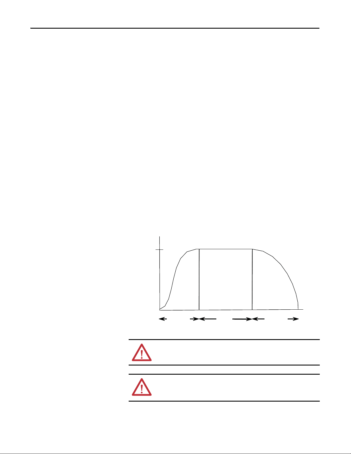
Perce nt
Volt age
100%
Initial
Tor qu e
Start
Time (seconds)
Run
SMC Flex™ Control Module
The MV SMC Flex controller offers a full range of starting and stopping modes
as standard:
• Soft Start with Selectable Kickstart
• Soft Stop
• Current Limit Start with Selectable Kickstart
• Linear Acceleration with Selectable Kickstart
• Linear Deceleration
• Dual Ramp Start
• Preset Slow Speed
• Full Voltage Start
Other features that offer further user benefit include:
• Extensive protection features
• Metering
• Communication capability
• I/O
(1)
Starting Modes
Innovative control option provides enhanced performance:
• Pump Control (Start and Stop Control modes)
These modes, features and options are further described in this chapter.
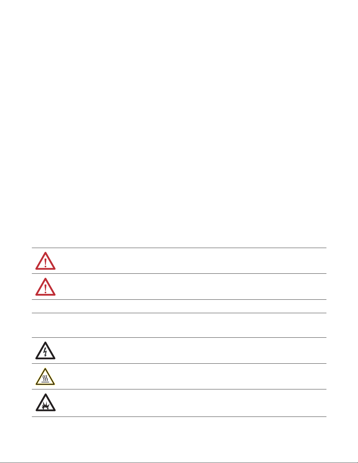
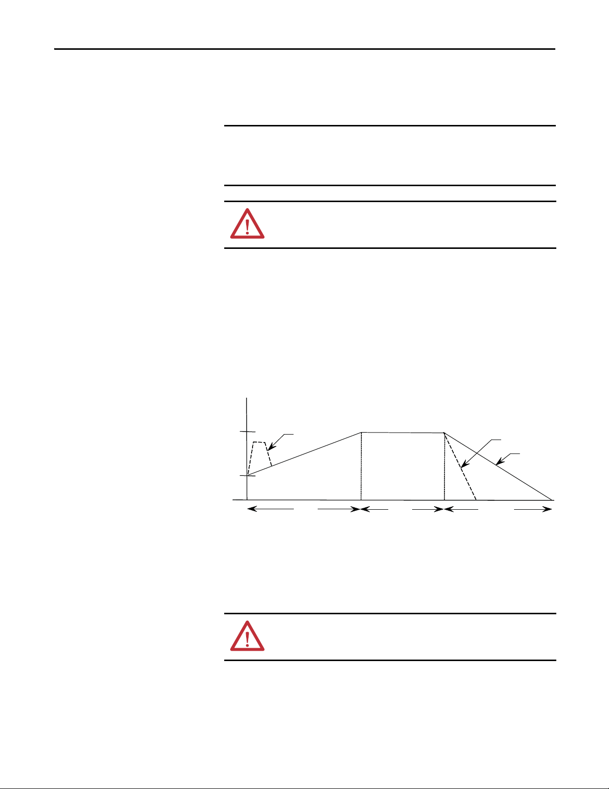
Soft Start
This mode has the most general application. The motor is given an initial torque
setting, which is user-adjustable from 0 to 90% of locked-rotor torque. From the
initial torque level, the output voltage to the motor is steplessly increased during
the acceleration ramp time. The acceleration ramp time is user-adjustable from 0
to 30 seconds. Once the MV SMC Flex controller senses that the motor has
reached the up-to-speed condition during the voltage ramp operation, the output
voltage automatically switches to full voltage, and the bypass contactor is closed.
Figure 1 - Soft Start
(1) This option utilizes gating patterns which result in motor and line currents that produce noise and vibration in the motor and/or
distribution transformer. This must be considered before applying this option.
Rockwell Automation Publication 1560E-UM051F-EN-P - June 2013 3
Page 14
Chapter 1 Product Overview
Kickstart
100%
Initial
Tor q ue
Start
Time (seconds)
Run
600%
Perce nt
Full Load
Curren t
Start
Time (se conds)
50%
Selectable Kickstart
(2)
Selectable kickstart provides a power boost at start-up that is user-adjustable from
0 to 90% of locked rotor torque. The additional power helps motors generate
higher torque to overcome the resistive mechanical forces of some applications
when they are started. The selectable kickstart time is user-adjustable from 0.0 to
2.0 seconds.
Figure 2 - Selectable Kickstart
Current Limit Start
(2)
This starting mode provides a true current limit start that is used when limiting
the maximum starting current is necessary. The Current Limit level is
user-adjustable from 50% to 600% of the motor’s full-load ampere rating, and the
current limit time is user-adjustable from 0 to 30 seconds. Once the MV SMC
Flex controller senses that the motor has reached the up-to-speed condition
during the current limit starting mode, the output voltage automatically switches
to full voltage and the bypass contactor is closed.
Figure 3 - Current Limit Start
4 Rockwell Automation Publication 1560E-UM051F-EN-P - June 2013
(2) Kickstart is also available with Current Limit Start, Dual Ramp Start and Linear Acceleration.
Page 15
Product Overview Chapter 1
Perce nt
Volt age
Start #1
Time (seconds)
Start #2
Ramp #2
Ramp #1
Start #2
Run #1
Run #2
Initial Torque #1
Initial Torque #2
100%
Perce nt
Vol tag e
Time (seconds)
100%
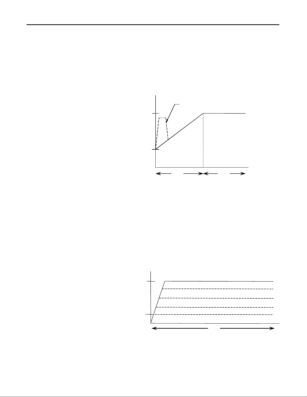
Dual Ramp Start
(3)
This starting mode is useful for applications that have varying loads (and
therefore varying starting torque requirements). Dual Ramp Start allows the user
to select between two separate Soft Start profiles with separately adjustable ramp
times and initial torque settings.
Figure 4 - Dual Ramp Start
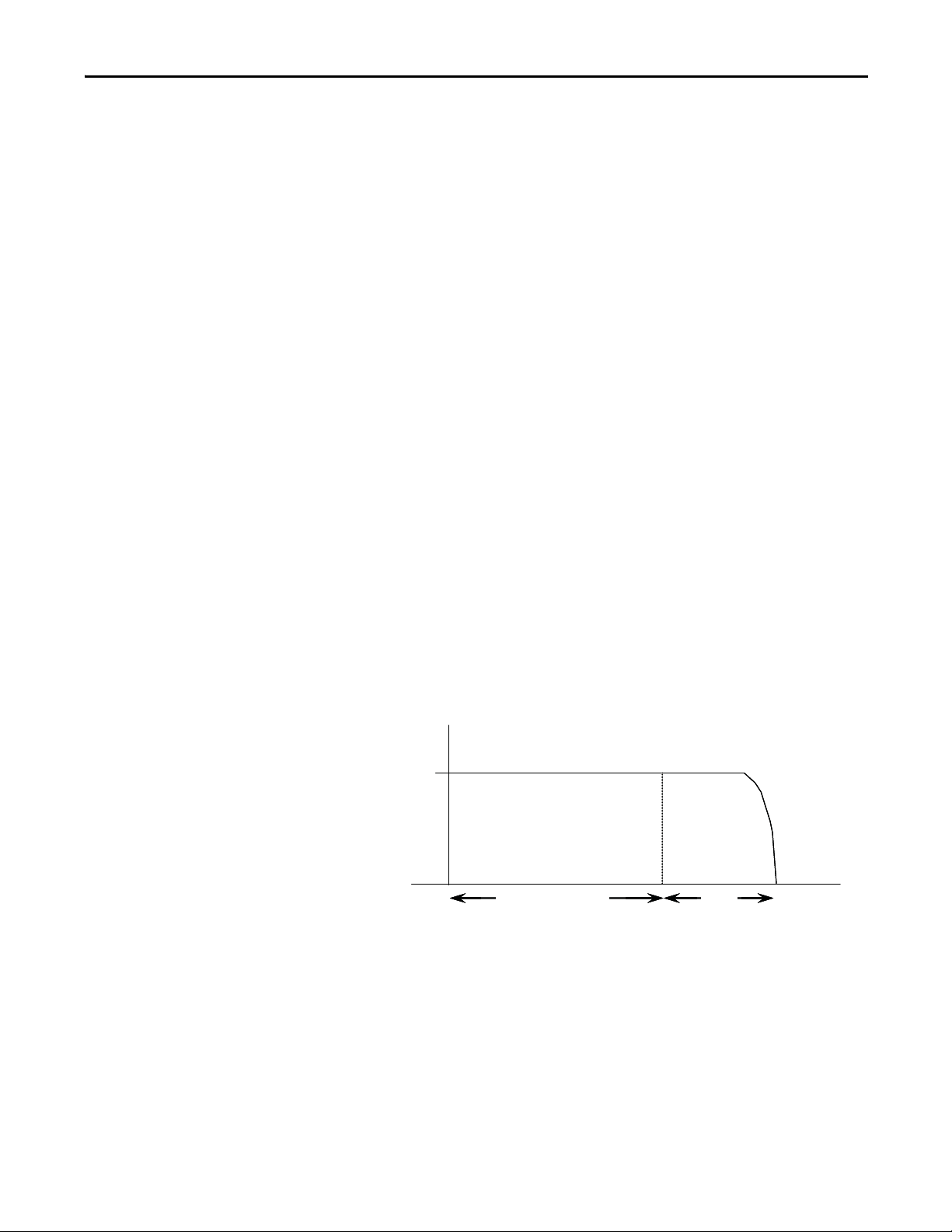
Full Voltage Start
This starting mode is used for applications requiring across-the-line starting. The
output voltage to the motor will reach full voltage within 1/4 second.
Figure 5 - Full Voltage Start
(3) Dual Ramp Start is available only with the standard controller.
Rockwell Automation Publication 1560E-UM051F-EN-P - June 2013 5
Page 16
Chapter 1 Product Overview
IMPORTANT
Forwa rd
15% – High
Time (seconds)
Start Run
10% – Low
Reverse
7% – Low
20% – High
100%
Motor
Speed
Run
Time (seconds)
Start Stop
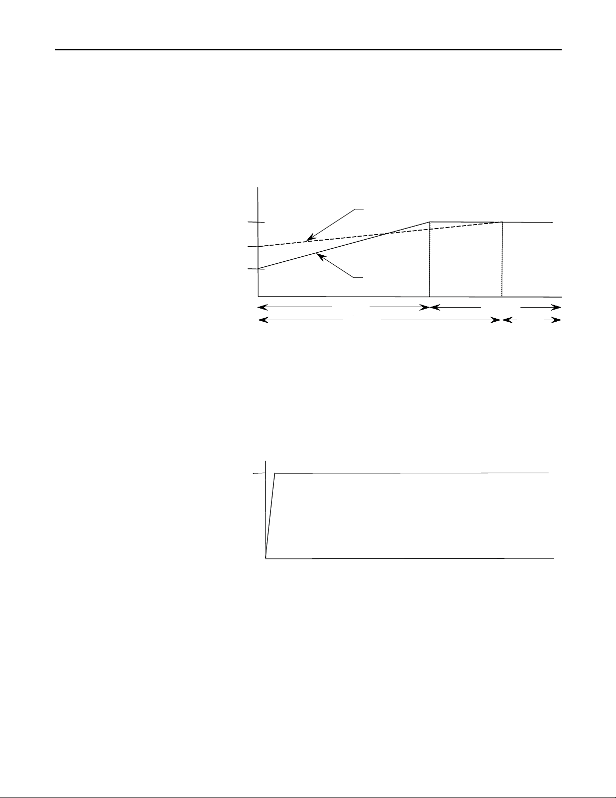
Preset Slow Speed
This option can be used in applications that require a slow-speed jog for general
purpose positioning. Preset Slow Speed provides either 7% of base speed (low) or
15% of base speed (high) settings in the forward direction. Reverse can also be
programmed and offers 10% of base speed (low) and 20% of base speed (high)
settings.
Figure 6 - Preset Slow Speed Option
Slow speed running is not intended for continuous operation due to reduced
motor cooling. The two starts per hour limitation also applies to slow speed
operation. This option employs a cycle-skipping scheme which produces
limited torque. Applications should be checked with the factory.
Linear Speed Acceleration and Deceleration
The SMC Flex has the ability to control the motor speed during starting and
stopping maneuvers. A tachometer signal (0 to 5V DC) is required to perform
this start mode. The start time is selectable from 0 to 30 seconds and determines
the time the motor will ramp from 0 speed to full speed. Kickstart is available
with this option.
Figure 7 - Linear Speed Acceleration
6 Rockwell Automation Publication 1560E-UM051F-EN-P - June 2013
Page 17
Product Overview Chapter 1
IMPORTANT
Kickstart
100%
Initial
Tor qu e
Perce nt
Vol tag e
Run
Time (seconds)
Start Soft Stop
Coast- to-rest
Soft Stop
TIP
Linear deceleration does not need to be used, even if linear acceleration is used.
The stop time can be programmed for 0 to 120 seconds. Linear deceleration
cannot brake the motor/load and reduce the stop time.
Consult factory if settings over 30 seconds are required. The base rating of the
MV SMC Flex is two starts (or one start/stop combination) per hour, thirty
seconds maximum for each operation. A stopping operation counts as a start
for purposes of thermal capacity calculations.
ATT EN TI ON : Linear Deceleration is not intended to be used as an emergency
stop. Such usage may result in severe injury or death. Refer to the applicable
standards for emergency stop requirements.
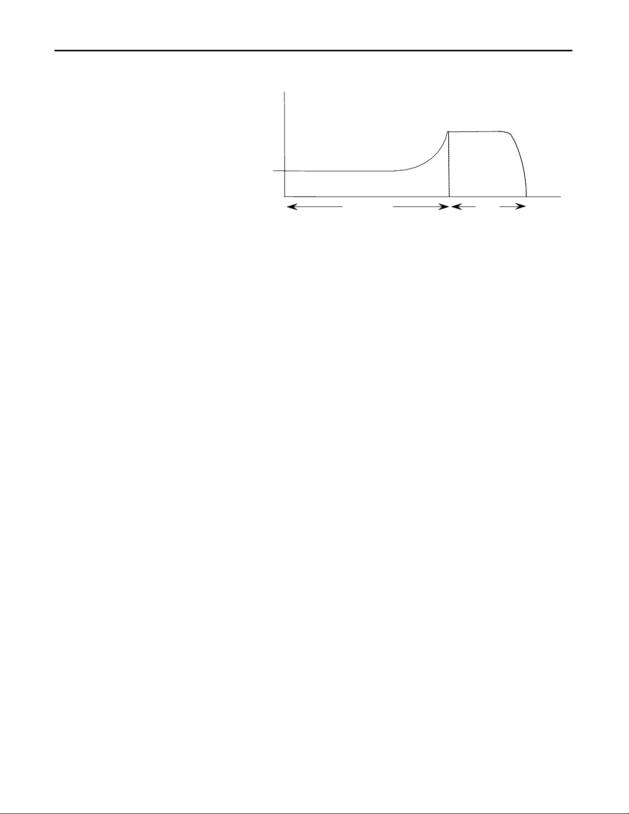
Soft Stop
This feature can be used in applications that require an extended coast-to-rest
time. The voltage ramp-down time is user-adjustable from 0 to 120 seconds and
is adjusted independently from the starting time. The load will stop when the
output voltage drops to a point where the load torque is greater than the
developed motor torque.
Figure 8 - Soft Stop Option
Consult factory if settings over 30 seconds are required. The base rating of the
MV SMC Flex is two starts (or one start/stop combination) per hour, thirty
seconds maximum for each operation. A stopping operation counts as a start
for purposes of thermal capacity calculations.
ATT EN TI ON : Soft Stop is not intended to be used as an emergency stop. Such
usage may result in severe injury or death. Refer to the applicable standards for
emergency stop requirements.
Rockwell Automation Publication 1560E-UM051F-EN-P - June 2013 7
Page 18

Chapter 1 Product Overview
IMPORTANT
Protection and Diagnostics
The MV SMC Flex controller is capable of providing the following protective
and diagnostic features:
Overload
The MV SMC Flex controller meets applicable requirements as a motor overload
protection device. Thermal memory provides added protection and is
maintained even when control power is removed. The built-in overload
algorithm controls the value stored in Parameter 12, Motor Thermal Usage
(Refer to Chapter 4,
value reaches 100%. The parameters below provide application flexibility and
easy setup.
Parame ter Range
Overload Class Disable, 10, 15, 20, 30
Overload Reset Manual – Auto
Motor FLC 10 – 2200 amps
Service Factor 0.01 – 1.99
Programming). An Overload Fault will occur when this
During slow speed operations, current waveforms exhibit non-sinusoidal
characteristics. These non-sinusoidal characteristics inhibit the controller's
current-measurement capability. To compensate for additional motor heating
that may result, the controller uses motor thermal modeling, which increments
motor thermal usage. This compensation takes place when the Preset Slow
Speed option is used.
Notes:
1. If the MV SMC Flex is used to control a multi-speed motor, or more than
one motor, the Overload Class parameter must be programmed to “OFF”
and separate overload relays must be supplied for each speed/motor.
2. Automatic reset of an overload fault requires the start input to be cycled in
a 2-wire control scheme.
3. The trip rating is 117% of the programmed FLC.
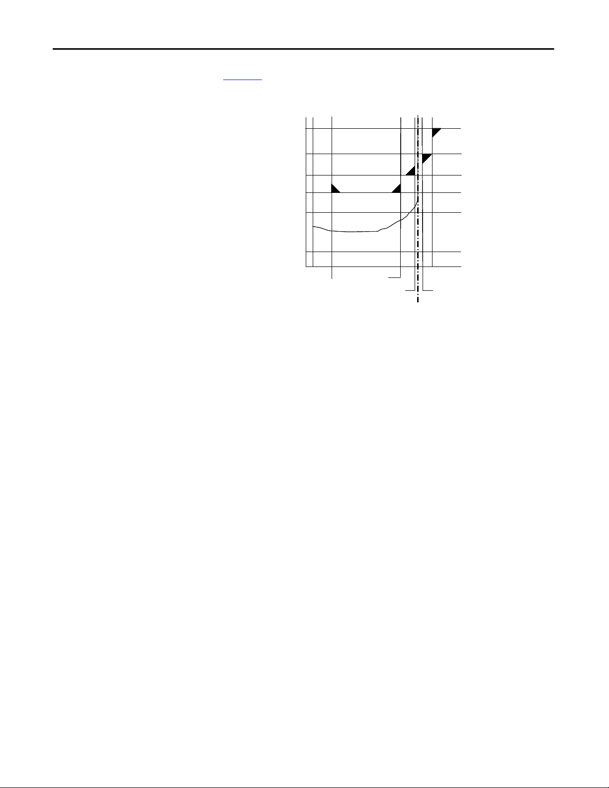
Figure 9
and Figure 10 provide the overload trip curves for the available trip
classes.
8 Rockwell Automation Publication 1560E-UM051F-EN-P - June 2013
Page 19
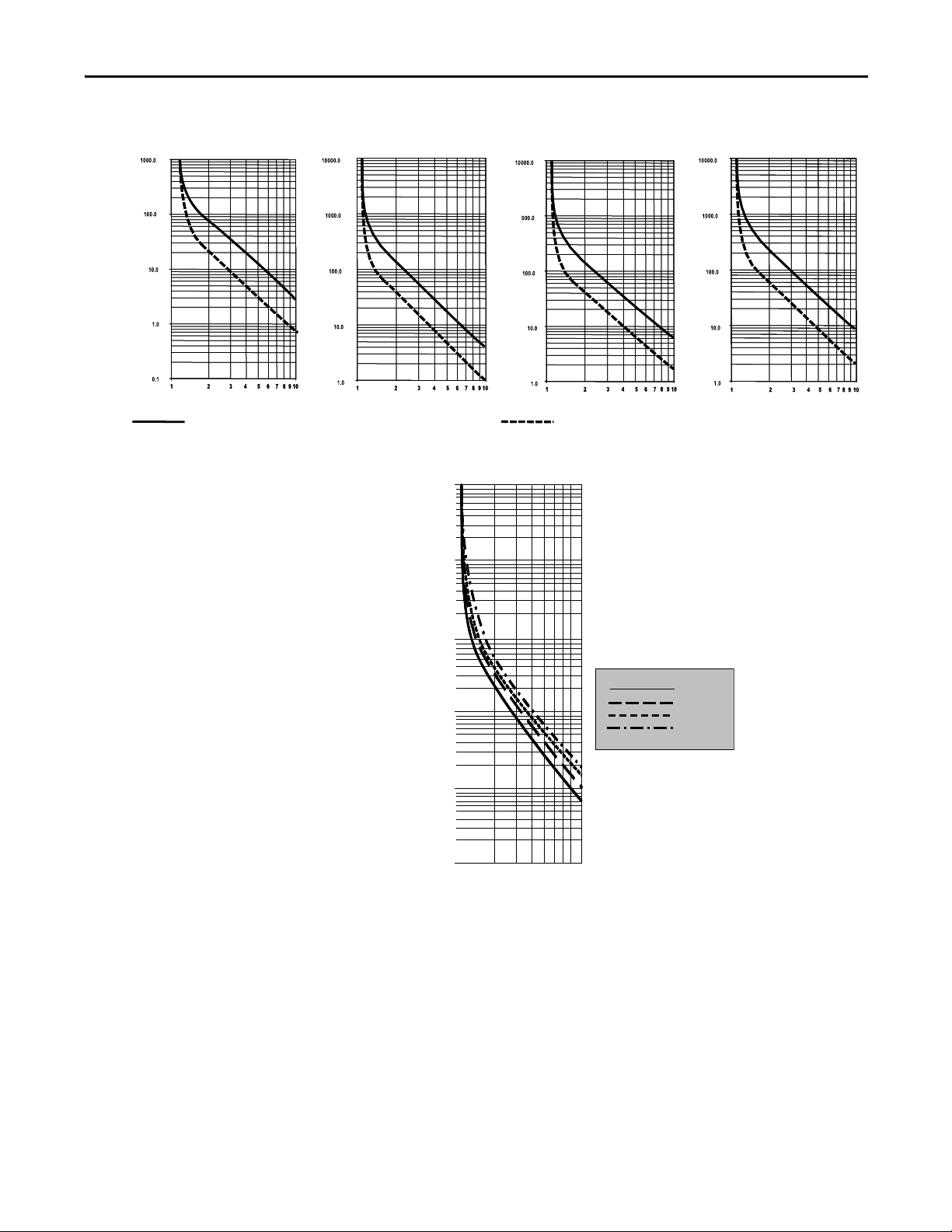
Figure 9 - Overload Trip Curves
Class 10 Class 15 Class 20 Class 30
Multiples of FLC Multiples of FLC Multiples of FLC
Approximate Trip Time (Seconds)
Approximate Trip Time (Seconds)
Approximate Trip Time (Seconds)
Approximate Trip Time (Seconds)
Approximate trip time for 3-phase
balanced condition from hot start
Approximate trip time for 3-phase
balanced condition from cold start
Percent Full Load Current Setting
Seconds
Class 10
Class 15
Class 20
Class 30
Auto Reset Times:
Class 10 = 90 s
Class 15 = 135 s
Class 20 = 180 s
Class 30 = 270 s
Figure 10 - Restart Trip Curves after Auto Reset
100000
100000
Product Overview Chapter 1
1000
1000
100
100
10
10
1
1
0
0
100% 1000%
100% 1000%
Rockwell Automation Publication 1560E-UM051F-EN-P - June 2013 9
Page 20

Chapter 1 Product Overview
TIP
TIP
Underload
(4)
Utilizing the underload protection of the MV SMC Flex controller, motor
operation can be halted if a sudden drop in current is sensed.
The MV SMC Flex controller provides an adjustable underload trip setting from
0 to 99% of the programmed motor full load current rating. Trip delay time can
be adjusted from 0 to 99 seconds.
Undervoltage
(5)
Utilizing the undervoltage protection of the MV SMC Flex, motor operation can
be halted if a sudden drop in voltage is detected.
The MV SMC Flex controller provides an adjustable undervoltage trip setting
from 0 to 99% of the programmed motor voltage. Trip delay time can be adjusted
from 0 to 99 seconds.
For medium voltage applications, undervoltage protection should be set from
80 to 99%.
An alarm (pre-fault) indication level can be programmed to indicate the unit is
getting close to faulting. The alarm modification information is displayed
through the LCD, HIM, Communication (if applicable) and alarm contact
closing.
Overvoltage
(5)
Utilizing the overvoltage protection of the MV SMC Flex, motor operation can
be halted if a sudden increase in voltage is detected.
The MV SMC Flex controller provides an adjustable overvoltage trip setting
from 0 to 199% of the programmed motor voltage. Trip delay time can be
adjusted from 0 to 99 seconds.
For medium voltage applications, overvoltage protection should be set from
100 to 115%.
An alarm (pre-fault) indication level can be programmed to indicate the unit is
getting close to faulting. The alarm modification information is displayed
through the LCD, HIM, Communication (if applicable) and alarm contact
closing.
(4) Underload protection is disabled during slow speed and braking operations.
(5) Undervoltage, overvoltage and voltage unbalance protection are disabled during braking operation.
10 Rockwell Automation Publication 1560E-UM051F-EN-P - June 2013
Page 21
Product Overview Chapter 1
Perce nt
Full Loa d
Curren t
600%
Programmed Start Time
Stall
Time (seconds)
Unbalance
(6)
The MV SMC Flex is able to detect an unbalance in line voltages. Motor
operation can be halted if the unbalance is greater than the desired range.
The MV SMC Flex controller provides an adjustable unbalance setting from 0 to
25% of the line voltages. Trip delay time can be adjusted from 0 to 99 seconds.
An alarm (pre-fault) indication level can be programmed to indicate the unit is
getting close to faulting. The alarm modification information is displayed
through the LCD, HIM, Communication (if applicable) and alarm contact
closing.
Stall Protection and Jam Detection
The MV SMC Flex controller provides both stall protection and jam detection
for enhanced motor and system protection.
• Stall protection is user-adjustable from 0.0 to 10.0 seconds (enabled only
after the programmed start time expires).
• An alarm (pre-fault) indication level can be programmed to indicate the
unit is getting close to faulting. The alarm modification information is
displayed through the LCD, HIM, Communication (if applicable) and
alarm contact closing.
• Jam detection allows the user to determine the jam level (up to 1000% of
the motor’s full-load current rating) and the delay time (up to 99.0
seconds) for application flexibility.
Figure 11 - Stall Protection
(6) Undervoltage, overvoltage, and voltage unbalance protection are disabled during braking operation.
Rockwell Automation Publication 1560E-UM051F-EN-P - June 2013 11
Page 22
Chapter 1 Product Overview
Perce nt
Full Loa d
Curren t
100%
Running
Jam
Time (seconds)
Figure 12 - Jam Detection
(7)
Ground Fault
In isolated or high impedance-grounded systems, core-balanced current sensors
are typically used to detect low level ground faults caused by insulation
breakdowns or entry of foreign objects. Detection of such ground faults can be
used to interrupt the system to prevent further damage, or to alert the
appropriate personnel to perform timely maintenance.
The MV SMC Flex’s ground fault detection capabilities consist of using a core
balance current transformer for 1 to 5A core-balanced ground fault protection
with the option of enabling Ground Fault Trip, Ground Fault Alarm, or both (a
core balance CT can be provided with 1562E units).
Ground Fault Trip
The MV SMC Flex will trip with a ground fault indication if:
• No trip currently exists
• Ground fault protection is enabled
• GF Inhibit Time has expired
• GF Current is equal to or greater than the GF Trip Level for a time period
greater than the GF Trip Delay
Parameter 75, Gnd Flt Inh Time, allows the installer to inhibit a ground fault trip
from occurring during the motor starting sequence and is adjustable from 0 to
250 seconds.
Parameter 74, Gnd Flt Delay, allows the installer to define the time period a
ground fault condition must be present before a trip occurs. It is adjustable from
0.1 to 25 seconds.
Parameter 73, Gnd Flt Level, allows the installer to define the ground fault
current at which the MV SMC Flex will trip. It is adjustable from 1.0 to 5.0 A.
(7) Jam Detection is disabled during slow speed and braking operation.
12 Rockwell Automation Publication 1560E-UM051F-EN-P - June 2013
Page 23

Product Overview Chapter 1
IMPORTANT
The ground fault inhibit timer starts after the maximum phase of load current
transitions from 0A to 30% of the device’s minimum FLA Setting or the GF
Curre nt is greater than or equal to 0.5 A. The MV SMC Flex does not begin
monitoring for a ground fault condition until the Gnd Flt Inh Time expires.
Ground Fault Alarm
The MV SMC Flex will indicate a Ground Fault Alarm if:
• No warning currently exists
• Ground fault alarm is enabled
• GF Inhibit Time has expired
• GF Current is equal to or greater than the Gnd Flt A Lvl
Parameter 77, Gnd Flt A Lvl, allows the installer to define the ground fault
current at which an alarm will be indicated. It is adjustable from 1.0 to 5.0 A.
Parameter 78, Gnd Flt A Dly, allows the installer to define the time period a
ground fault alarm condition must be present before a trip occurs. It is adjustable
from 0.1 to 25 seconds.
Thermistor/PTC Protection
The MV SMC Flex provides terminals 23 and 24 for the connection of positive
temperature coefficient (PTC) thermistor sensors. PTC sensors are commonly
embedded in motor stator windings to monitor the motor winding temperature.
When the motor winding temperature reaches the PTC sensor’s temperature
rating, the PTC sensor’s resistance transitions from a low to high value. Since
PTC sensors react to actual temperature, enhanced motor protection can be
provided to address such conditions as obstructed cooling and high ambient
temperatures.
Ta b l e 1
Table 1 - PTC Input Ratings
defines the MV SMC Flex PTC thermistor input and response ratings:
Response Resistance 3400 ± 150
Reset Resistance 1600 ± 100
Short-circuit Trip Resistance 25 ± 10
Maximum Voltage at PTC Terminals (R
Maximum Voltage at PTC Terminals (R
Maximum Number of Sensors 6
Maximum Cold Resistance of PTC Sensor Chain 1500
Response Time 800 ms
- 4k) < 7.5V
PTC
= open) 30V
PTC
Rockwell Automation Publication 1560E-UM051F-EN-P - June 2013 13
Page 24
Chapter 1 Product Overview
TNF + 15K
TNF + 5K
TNF - 20K
TNF - 5K
TNF
-20°C
0°C
Figure 13 illustrates the required PTC sensor characteristics, per IEC-34-11-2.
Figure 13 - PTC Sensor Characteristics per IEC-34-11-2
4000
4000
4000
4000
1330
1330
1330
1330
550
550
550
550
250
250
250
250
100
100
100
100
20
20
20
20
10
10
10
10
PTC Trip
The MV SMC Flex will trip with a PTC indication if:
• No other fault currently exists
• PTC protection is enabled
• The resistance across terminals 23 and 24 is either greater than the relay’s
response resistance or less than the short-circuit trip resistance.
Open Gate
An open-gate fault indicates that improper SCR firing, typically caused by an
open SCR gate or driver system, has been detected on one of the power poles.
Before the controller shuts down, it will attempt to start the motor a total of three
times (or as programmed in Parameter 82).
An open gate is detected when the module sends a gate signal to the SCRs but
does not detect that they turned on. SCR turn-on is detected when the voltage
across the leg (L-T) collapses. The Open Gate detection is active during starting
or stopping only.
14 Rockwell Automation Publication 1560E-UM051F-EN-P - June 2013
Page 25

Product Overview Chapter 1
TIP
Line Faults
The MV SMC Flex controller continually monitors line conditions for abnormal
factors. Pre-start protection includes:
• Line Fault (with phase indication)
– Line voltage loss
– Missing load connection
– Shorted SCR
Running protection includes:
• Line Fault (no phase indication)
– Line voltage loss
– Missing load connection
(8)
Phase reversal protection
can be toggled either ON or OFF.
Excessive Starts/Hour
The MV SMC Flex module allows the user to program the desired number of
starts per hour (up to 99). This helps eliminate motor stress caused by repeated
starting over a short time period.
The base rating of the MV SMC Flex is two starts (thirty seconds each max.) per
hour. Applications requiring more frequent starts, or longer duration starts,
should be reviewed with the factory to avoid equipment damage.
Overtemperature
The power module temperature is monitored during starting and stopping
maneuvers by thermistors. The thermistor is connected to the gate driver board
where it is processed, and the status is transmitted by fiber-optic cable through
the interface board to the control module. When an overtemperature condition
exists (>85°C), the control module trips and indicates a “PTC Power Pole” fault.
An overtemperature condition could indicate high ambient temperature,
overloading or excessive cycling. After the power module temperature is reduced
to allowable levels, the fault can be cleared (Refer toTroubleshooting
page 113 for instructions).
on
(8) Phase reversal protection is functional only at pre-start.
Rockwell Automation Publication 1560E-UM051F-EN-P - June 2013 15
Page 26

Chapter 1 Product Overview
TIP
Metering
Power monitoring parameters include:
• Three-phase current
• Three-phase voltage
• Power in MW
• Power usage in MWh
• Power factor
• Motor thermal capacity usage
• Elapsed time
• Motor speed (full speed %, with use of optional tachometer input)
Notes:
1. Voltage measurement is not available during the braking operation of the
SMB Smart Motor Braking, Accu-Stop, and Slow Speed with Braking
control options.
2. The elapsed time and MWh values are automatically saved to memory
every 12 hours.
3. Motor thermal capacity usage is determined by the built-in electronic
thermal overload. An overload fault occurs when this value reaches 100%.
I/O
The SMC Flex has the ability to accept up to two (2) inputs and four (4) outputs
controlled over a network. The two inputs are controlled at terminal 16 (Option
Input #1), and terminal 15 (Option Input #2). For these two inputs, refer
to Chapter 4
identification. By using these two terminals as inputs, the Stop Input will need to
be programmed to meet the desired stop functionality.
The four (4) outputs are Aux #1, Aux #2, Aux #3 and Aux #4. All auxiliary
contacts are programmable to the function found on page 83
Network or Network NC, they can be controlled over a Network. Please see
Table 16 on page 109
for the parameter settings and refer to Chapter 8 for the bit
. If programmed to
which defines the Logic Command Word (Control).
For MV applications, some of the I/O are assigned to specific functions. Please
refer to Status Indication
on page 18 for additional details.
16 Rockwell Automation Publication 1560E-UM051F-EN-P - June 2013
Page 27
Product Overview Chapter 1
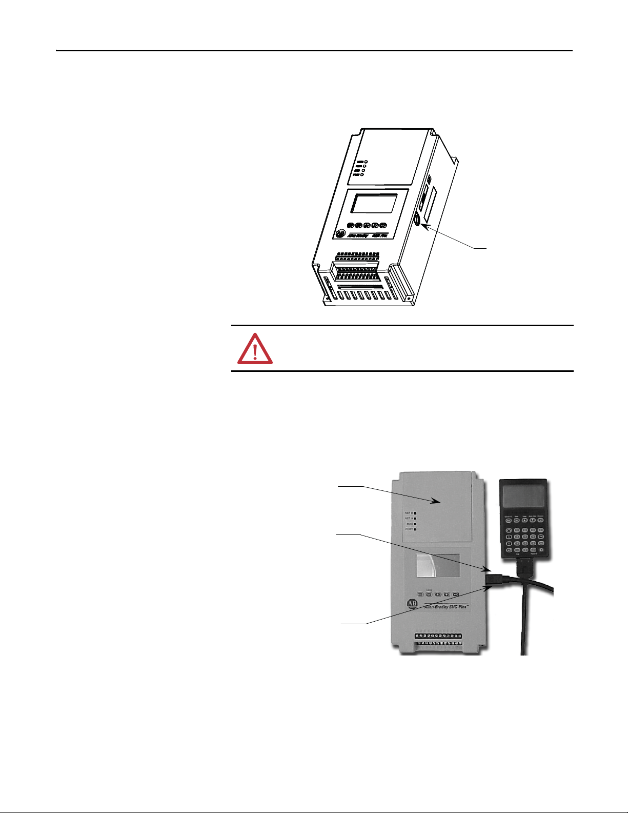
DPI
Port 2
Ports 2 and 3 when two HIMs
are connected with a splitter
Port 5 – DPI Communications
Communication
A serial interface port (DPI) is provided as standard, which allows connection to
the Bulletin 20-HIM LCD human interface modules.
Figure 14 - DPI Location
ATT EN TI ON : Two peripheral devices can be connected to the DPI. The
maximum output current through the DPI is 280 mA.
Programming
Setup is easy with the built-in keypad and three-line, sixteen-character backlit
LCD. Parameters are organized in a three-level menu structure, using a text
format for straightforward programming.
Figure 15 - Built-in Keypad and LCD
Rockwell Automation Publication 1560E-UM051F-EN-P - June 2013 17
Page 28
Chapter 1 Product Overview
TIP
SMC Flex Controller Terminals
Opt
Input
#2
Opt
Input
#1
Start
Input
Stop
Input
(External
Bypass)
Aux #1
PTC
Input
TACH
Input
Ground
Faul t
(Fault
Contac t)
Aux 2 Aux 3 Aux 4
(Alarm
Contac t)
(Normal)
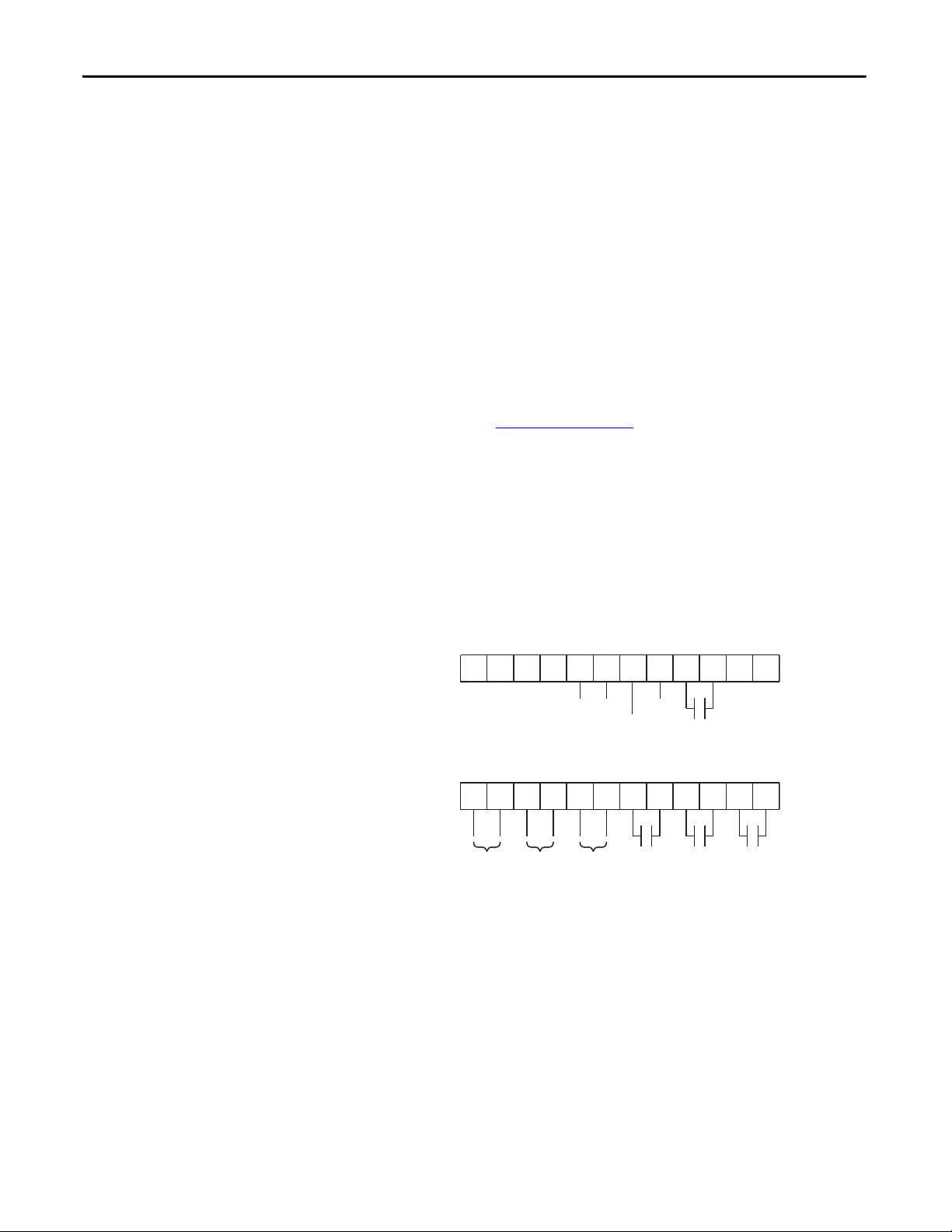
Status Indication
All auxiliary contacts can be programmed as NO or NC for the following states
except External Bypass, which can only be programmed as NO.
Normal/Normal NC: The contact state changes when the unit receives a
Start/Stop signal
Up-to-Speed/Up-to-Speed NC: The contact state changes when the motor
approaches rated speed
Alarm/Alarm NC: The contact state changes when an Alarm condition is
detected
Fault/Fault NC: The contact state changes when a Fault condition is detected
Network Control/Network Control NC: The contact state is controlled over
the network. (Refer to Table 16 on page 109
, which describes logic command
word to control auxiliary outputs)
External Bypass: This contact controls the Bypass contactor for MV
applications.
The tag name without a suffix indicates a NO state (e.g. Normal). On the other
hand, a tag name followed by NC indicates a normally closed state (e.g. Normal
NC).
Figure 16 - Control Terminals
a
20
11 12
23
13
25
24
15
14
26
27
17
16
28
29
Note:
• The Aux #1 contact is always programmed for External Bypass (NO) to
control the bypass contactor in MV applications.
• The Aux #2 contact is typically programmed for fault indication in MV
applications (it can be configured for NO/NC).
• The Aux #3 contact is typically programmed for alarm indication in MV
applications (it can be configured for NO/NC).
• The Aux #4 contact is always configured as Normal (NO) to control the
line contactor for MV applications.
19
18
30
31
21
22
33
32
34
18 Rockwell Automation Publication 1560E-UM051F-EN-P - June 2013
Page 29

Product Overview Chapter 1
IMPORTANT
Network inputs can be obtained through proper programming of Option Input
#1 and Option Input #2. (refer to page 159
MV applications have special requirements for isolation and bypass contactors
(or circuit breakers). For Firmware up to and including 5.001 the following
issues must be considered:
1. AUX1 must be used to control the fully-rated bypass contactor.
Parameters #107 will not be displayed, and defaults to “Ext Bypass”. The
functionality of AUX1 is modified for MV operation and behaves similar
to, but different from, the “Ext Bypass” or “Up-To-Speed” function of any
other AUX relay.
2. AUX4 must be used to control the isolation contactor. Parameter #109
must be set to “Normal”. The functionality of AUX4 is modified for MV
operation and behaves similar to, but different from, the “Normal”
function of any other AUX relay.
For Firmware 6.001 and later, the definitions of all AUX relays will be the same,
and for MV applications will perform with the modified MV functionality.
and page 163 for available options.)
Control Options
1. AUX1 should be used for bypass contactor control, and must be set for
“Ext Bypass”.
2. AUX4 should be used for isolation contactor control, and must be set for
“Normal”.
The MV SMC Flex controller offers the control options described below.
The options listed in this section are mutually exclusive and must be specified
when ordering. An existing controller may be upgraded to another control
option by replacing the control module and possibly other components.
Consult your nearest Rockwell Automation sales office.
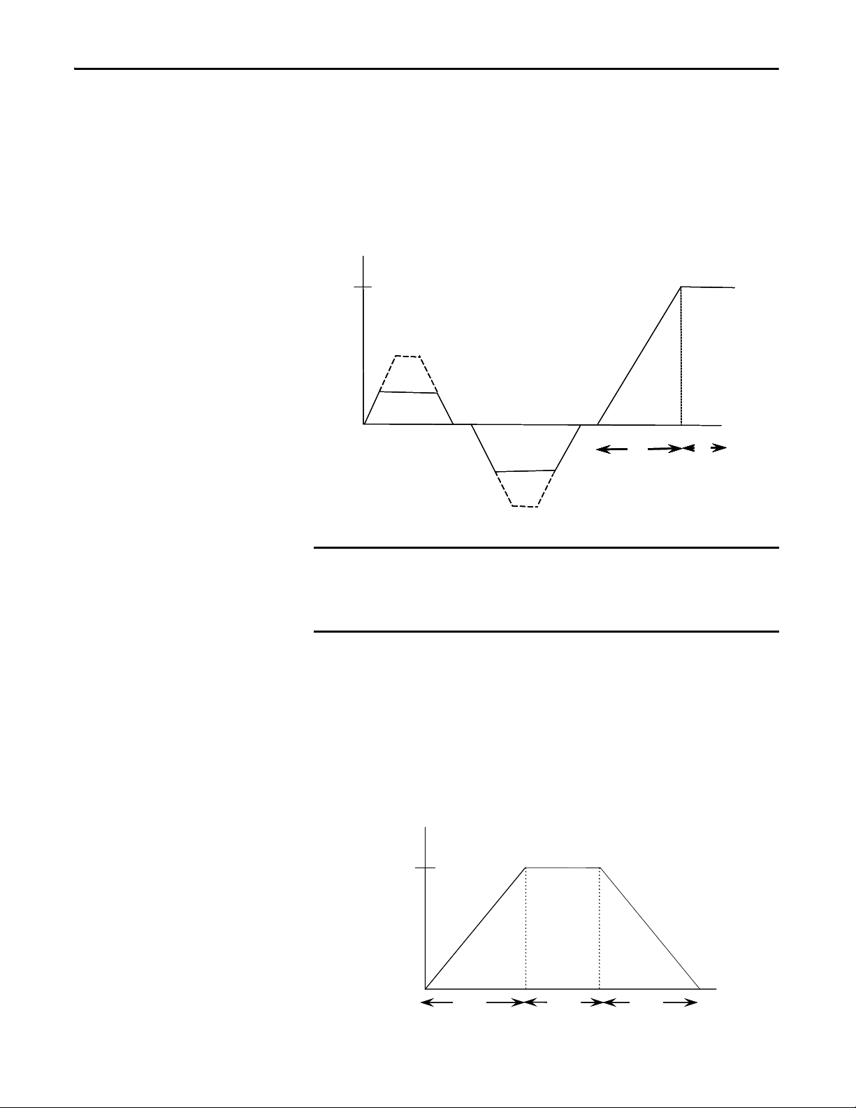
Pump Control Option
This option reduces surges during the starting and stopping of a centrifugal pump
by smoothly accelerating and decelerating the motor. The microprocessor
analyzes the motor variables and generates commands that control the motor and
reduce the possibility of surges occurring in the system.
The motor current will vary during the acceleration period, and may be near the
motor rated starting current. The pump algorithm does not limit starting current
since full voltage is needed to reach full speed with a loaded motor.
The starting time is programmable from 0-30 seconds, and the stopping time is
programmable from 0-120 seconds.
Kickstart is available with this option.
Rockwell Automation Publication 1560E-UM051F-EN-P - June 2013 19
Page 30
Chapter 1 Product Overview
100%
Motor
Speed
Run
Pump StopPump Start
Time (seconds)
Pump Application Considerations
1. Consult factory if start time settings over 30 seconds are required. The
base rating of the MV SMC Flex is two starts (or one start/stop
combination) per hour, thirty seconds maximum for each operation. A
stopping operation counts as a start for purposes of thermal capacity
calculations.
2. The Pump Control option functions only for centrifugal pumps. It is not
suited for positive displacement, piston, or other types of pumps.
3. The Pump Stop option functions only for a centrifugal pump running at
greater than approximately 2/3 of the motor rated horsepower.
4. Pump applications with input and/or output valves that are closed during
starting and/or stopping may not benefit from the Pump Control option.
Consult the factory for applications with valves.
5. For starting or stopping times longer than 15 seconds, power fuse selection
should be reviewed to ensure no element damage occurs. The fuse
minimum melting time-current characteristic curve should be consulted to
ensure that, at 1.1 times the full voltage locked rotor current of the motor,
the actual starting or stopping time does not exceed 75% of the fuse
melting time.
6. Motor overload and/or upstream breaker settings may have to be adjusted
to allow the starting or stopping current to flow for extended periods.
Figure 17 - Pump Control Option
ATT EN TI ON : Pump stopping is not intended to be used as an emergency stop.
Refer to the applicable standard for emergency stop requirements.
ATT EN TI ON : Pump stopping may cause motor heating depending on the
mechanical dynamics of the pumping system. Therefore, select the lowest
stopping time setting that will satisfactorily stop the pump.
20 Rockwell Automation Publication 1560E-UM051F-EN-P - June 2013
Page 31

Product Overview Chapter 1
Braking Control Options
The Braking Control options (Smart Motor Braking, Accu-Stop and Slow Speed
with Braking) are not offered for standard use in MV applications. Please consult
factory for further assistance.
Hardware Description
The following sections contain descriptions of system components and system
operation. Each section will be described to give the user an understanding of the
MV SMC Flex to facilitate operation and maintenance of the system. Refer to
Figure 18
and Figure 19, Typical MV SMC Flex Power System.
Power Module
The controller consists of three power modules, one for each phase. Each power
module consists of incoming and outgoing terminals for cables, SCRs, heatsink
and clamp assembly. The SCRs are connected in inverse parallel (and in series for
12- or 18-SCR assemblies) to form a three-phase, AC line controller
configuration.
Each power module includes a snubber circuit to limit the rate of rise in voltage
across each SCR pair. The module also includes patented current loop gate driver
circuits which derive their power primarily from the snubber circuit.
Voltage sharing resistors are connected across each SCR pair to provide static
voltage balance for series-connected SCRs. These resistors are tapped to provide
a reference for overvoltage protection circuitry on the gate driver board.
A voltage sensing board is used to reduce the line-side and load-side voltages to
lower levels that can be measured by the SMC Flex control module.
Current Loop Gate Driver (CLGD) Board
This board provides the turn-on capability for SCR devices. The board also
provides optical fiber isolation between itself and the gating source logic. It is
primarily powered by recovering energy from the snubber circuit, so it is fully
isolated from the control and logic circuits. The board also receives short-term
power from the current loop power supply.
The MV SMC Flex has three heatsinks fitted with a thermistor to monitor
temperature rise. The circuitry on the gate driver board accepts the thermistor,
and drives a fiber-optic cable if the temperature is below the setpoint (85°C). If
the temperature rises above the setpoint, the driver is turned off, and the MV
SMC Flex is signaled to stop gating and initiate a temperature fault.
Rockwell Automation Publication 1560E-UM051F-EN-P - June 2013 21
Page 32

Chapter 1 Product Overview
Interface Board
This circuit board takes current transformer signals plus line-side and load-side
voltage feedback signals from the voltage sensing board and passes them to the
SMC Flex for processing. The control module produces gating signals for the
SCRs, which are received on the interface board, and used to drive fiber-optic
transmitters. The gating signals are sent to the gate-driver circuit board via
fiber-optic cables. The interface board also receives temperature feedback from
the gate-driver board via fiber-optic cable(s). If the heatsink temperature rises
above a set value, a signal is sent to the SMC Flex to stop gating the SCRs and
initiate a temperature fault.
For a detailed layout of this circuit board, refer to Figure 37 on page 63
.
22 Rockwell Automation Publication 1560E-UM051F-EN-P - June 2013
Page 33

Product Overview Chapter 1
C
A
B
C
A
B
G
G
2
1
4
3
-+ +- -+ +-
A
B
4160V AC, 3Ø, 60Hz
L1 L2 L3 GND
ISOLATING SWITCH
DOOR INTERLOCK
IS
CURRENT LIMITING
POWER FUSES
CURRENT LIMITING
PRIMARY FUSES
F1
F1
F1
100:1
GFCT
(OPTIONAL)
F2F2
H2H1
120V
CPT
500VA
ISa
X3 X2 X4
4200V
TO CONTROL CIRCUIT
TO SMC Flex
(27, 28)
M
BLK
W
X1
B
RR1 RR2
OV1
OV2OV1 OV2OV2 OV3 OV4
S1 S2 S3 S4
RS1 RS2CS1 CS2
C1
C2 C3 C4
OV S C
TEST
CLGD
CT
RX1 TX1
G C T
OV S C
TEST
CLGD
CT
RX1 TX1
G C T
OV S C
TEST
CLGD
CT
RX1 TX1
G C T
OV S C
TEST
CLGD
CT
RX1 TX1
G C T
L1
L2
L3
CL
CT2
CT1
CT3
MTR
T1
T2
T1
CAUTION MAXIMUM TWO STARTS PER HOUR WITH A MINIMUM OF
FIVE MINUTES BETWEEN STARTS.
WIRE CONNECTIONS FOR PHASE A
WIRE CONNECTIONS FOR PHASE B
CONNECTIONS SHOWN FOR PHASE C
CONNECT TO GROUND ONLY IF POWER SYSTEM IS GROUNDED
CURRENT LOOP CONDUCTORS PASS THROUGH THE C.T.'S ON
THE GATE DRIVER BOARDS (CLGD)
REMOTE EQUIPMENT
SMC Flex INTERFACE BOARD SMC
FlexIB
VOLTAGE SENSING BOARD
VSB
GATE TRANSMITTERS
PHASE A PHASE B
OUTPUTS
TX1
TX2
TX3
TX4
TX5
TX6
TX7
TX8
TX9
TX10
TX11
TX12
TX13
TX14
TX15
TX16
TX17
TX18
U16
U18
U20
TEMP.
POWER
IN
POWER
OUT
FROM CONTROL
CIRCUIT
TB1
L1
L2/N
G
J3
TO SMC Flex
(11, 12)
TB5
A-
A+
B-
B+
C-
C+
TB6
TB21
VSB
Vcom
GDPS FROM CLT
24C
L1T1L2T2L3
T3
GND1 GND2
1B2B3B4B5B
6B
A: 4800-7200V
B: 2500-4799V
C: 1450-2499V
D: 800-1449V
PHASE C
J1
Figure 18 - Typical MV SMC Flex Power System • Bulletin 1562E (3300/4160V shown)
Rockwell Automation Publication 1560E-UM051F-EN-P - June 2013 23
Page 34

Chapter 1 Product Overview
C
A
B
C
A
B
A
B
G
G
2
1
4
3
-+
+- -+
+-
A IN
B
RR1 RR2
OV1
OV2 OV3 OV4
S1 S2 S3 S4
RS1 RS2CS1 CS2
C1
C2 C3 C4
OV S C
TEST
CLGD
CT
RX1 TX1
G C T
L1
L2
L3
CL
CT2
CT1
CT3
MTR
A OUT
CAUTION MAXIMUM TWO STARTS PER HOUR WITH A MINIMUM OF
FIVE MINUTES BETWEEN STARTS.
WIRE CONNECTIONS FOR PHASE A
WIRE CONNECTIONS FOR PHASE B
CONNECTIONS SHOWN FOR PHASE C
CONNECT TO GROUND ONLY IF POWER SYSTEM IS GROUNDED
CURRENT LOOP CONDUCTORS PASS THROUGH THE C.T.'S ON
THE GATE DRIVER BOARDS (CLGD)
REMOTE EQUIPMENT
SMC Flex INTERFACE BOARD SMC
FlexIB
VOLTAGE SENSING BOARD
VSB
GATE TRANSMITTERS
PHASE A PHASE B
OUTPUTS
TX1
TX2
TX3
TX4
TX5
TX6
TX7
TX8
TX9
TX10
TX11
TX12
TX13
TX14
TX15
TX16
TX17
TX18
U16
U18
U20
TEMP.
POWER
IN
POWER
OUT
FROM CONTROL
CIRCUIT
TB1
L1
L2/N
G
J3
TO SMC Flex
(11, 12)
TB5
A-
A+
B-
B+
C-
C+
TB6
TB21
VSB
Vcom
GDPS FROM CLT
24C
L1T1L2T2L3
T3
GND1 GND2
1B2B3B4B5B
6B
A: 4800-7200V
B: 2500-4799V
C: 1450-2499V
D: 800-1449V
PHASE C
OV S C
TEST
CLGD
CT
RX1 TX1
G C T
OV S C
TEST
CLGD
CT
RX1
TX1
G C T
OV S C
TEST
CLGD
CT
RX1 TX1
G C T
B IN
C IN
B OUT
C OUT
J1
Figure 19 - Typical MV SMC Flex Power System • Bulletin 1560E (3300/4160V shown)
24 Rockwell Automation Publication 1560E-UM051F-EN-P - June 2013
Page 35

Product Overview Chapter 1
Functional Description
The following functional descriptions and associated control circuits are for units
using IntelliVAC contactor control modules. For units with electromechanical
(relay) control, refer to Appendix C
ATT EN TI ON : The control circuit schematics shown below assume that control
power is fed from the same source as the primary circuit. If external control
power is used, additional control interlocking may be required to avoid
unexpected motor start-up. The control interlock should ensure that a motor
start request is not inadvertently applied when the primary circuit is
disconnected.
.
Bulletin 1562E • Basic Control – Controlled Start only
When wired as shown in Figure 20, the controller operates as follows:
Pressing the “Start” button initiates the start sequence. Relay “CR” closes and
applies control power to terminal 17 of the SMC Flex module. The Aux #4
(“Normal”) closes, energizing “M-IV” and “MCX”, which completes the hold-in
circuit on the start button, and closes the main contactor.
The SMC Flex module examines the line voltage, looks for fault conditions,
checks phase rotation, calculates zero crossing information, and begins gating the
SCRs to start the motor.
When the motor approaches rated speed, the SMC Flex module closes the
“Aux #1” (Ext. Bypass) auxiliary contacts, energizing “B-IV”, which closes the
bypass contactor. The motor then runs at full line voltage.
When the “Stop” button is pressed, the “CR” relay opens terminal 17 on the
SMC Flex module. The “Normal” contact opens, dropping out the main
contactor, allowing the motor to stop. The “Aux #1” contact is held closed for a
short time by the control module. This holds the bypass contactor closed for
about 10 seconds to protect the power electronics from any voltage transients due
to opening the motor circuits.
Bulletin 1562E • Basic Control – With Controlled Stop
When wired as shown in Figure 21, the controller operates in much the same
manner as in Figure 20
Terminal 16 on the SMC Flex module now controls the start and stop
maneuvers. Terminal 16 must remain energized for the module to run. When the
“Stop” button is pressed, and “CR” opens, the SMC Flex module will initiate the
option stop. An uncontrolled, or coast stop, is achieved by opening the
connection to terminal 17. This contact should remain open to ensure all hold-in
contacts clear, to prevent a re-start.
.
Rockwell Automation Publication 1560E-UM051F-EN-P - June 2013 25
Page 36

Chapter 1 Product Overview
If the motor has started, the unit is in the bypass mode, and a trip occurs within
the SMC Flex module or from an external protection relay; “Aux #4” will open
the line contactor immediately, and “Aux #1” will remain closed for 10 seconds to
protect the power electronics from any voltage transients due to opening the
motor circuits. A trip due to an overload or fault condition will result in a “coast”
stop.
Bulletin 1562E • DPI Control – Controlled Start only
The control scheme shown in Figure 22 allows the MV SMC Flex to be
controlled using DPI (Drive Programming Interface). (Table 16 on page 109
Logic Command Word bits assignment for DPI control.) This special usage of
DPI includes provisions for a “Local” mode of control as well.
With the Local-Off-Remote selector switch in the “Remote” position, terminal
18 of the SMC Flex module is energized, allowing a start command to be
executed via DPI. When a “Start” is executed, the “Aux #4” contact closes,
energizing both “M-IV” and “MCX”. The line contactor closes and the unit
initiates a start sequence.
for
When the motor approaches rated speed, the SMC Flex module closes “Aux #1”,
energizing “B-IV”, which closes the bypass contactor.
To run in “Local” mode, the “CR” contact is used to initiate a start sequence
(similar to Figure 20
A stop command can be generated via DPI or by opening “CR”, depending on the
control mode.
).
Bulletin 1562E • DPI Control – With Controlled Stop
The control scheme shown in Figure 23 allows the MV SMC Flex to be
controlled using DPI (Drive Programming Interface). (Table 16 on page 109
Logic Command Word bits assignment for DPI control). This special usage of
DPI includes provisions for a “Local” mode of control as well.
With the Local-Off-Remote selector switch in the “Remote” position, terminal
18 of the SMC Flex module is energized, allowing start and stop maneuvers to be
executed via DPI. When a “Start” is executed, the “Aux #4” contact closes,
energizing both “M-IV” and “MCX”. The line contactor closes and the unit
initiates a start sequence.
for
When the motor approaches rated speed, the SMC Flex module closes “Aux #1”,
energizing “B-IV”, which closes the bypass contactor. When a “Stop” is executed,
the unit opens “Aux #1”. The bypass contactor opens and the unit initiates a
controlled stop sequence, followed by opening of “Aux #4”, which opens the line
contactor.
26 Rockwell Automation Publication 1560E-UM051F-EN-P - June 2013
Page 37

Product Overview Chapter 1
An uncontrolled, or coast stop, can be achieved via DPI or by opening the
connection on terminal 18 (i.e. by pressing “Coast Stop” button).
When using the optional HIM, pressing the “Jog” button will initiate the
optional stop maneuver, and pressing the “O” button will initiate a coast stop.
To run in “Local” mode, the “CR” contact is used to initiate a start and stop
sequence (similar to Figure 21
). An uncontrolled, or coast stop, is achieved by
opening the connection on terminal 17. This contact should remain open to
ensure all hold-in contacts clear, to prevent a re-start.
If the motor has started, the unit is in bypass mode, and a trip occurs within the
SMC Flex module or from an external protection relay, “Aux #4” will open the
line contactor immediately, and “Aux #1” will remain closed for 10 seconds to
protect the power electronics from any voltage transients due to opening the
motor circuits. A trip due to an overload or fault condition will result in a
“Coast” stop.
Bulletin 1560E • Basic Control – Controlled Start only
The Bulletin 1560E is intended for addition to an existing motor controller,
which provides circuit isolation, motor switching, and overload and overcurrent
protection. When wired as shown in Figure 24
, the controller operates as follows:
When a start is initiated in the existing motor controller and the contactor (or
breaker) closes, a contact must be supplied to tell the 1560E to start also. A “CR”
contact will apply control voltage to terminal 17 of the SMC Flex module.
When stopping the motor, the contactor in the existing controller will open,
removing power from the motor, and then the “CR” relay. The bypass hold-in
rung will keep the bypass contactor closed for 10 seconds to protect the power
electronics from any voltage transients due to opening the motor circuits.
The “Fault” contact on the SMC Flex module should be wired into the existing
controller to trip the main contactor (or breaker) in the event of a fault condition
sensed by the SMC Flex module.
If possible, it is better to have the SMC Flex module control the main contactor
directly. In this case, the control circuit would look like, and function like, the
descriptions above for the Bulletin 1562E.
Rockwell Automation Publication 1560E-UM051F-EN-P - June 2013 27
Page 38

Chapter 1 Product Overview
Bulletin 1560E • Basic Control – With Controlled Stop
When wired as shown in Figure 25, the controller operates much the same as
described above for the Standard module. The control signal uses terminal 16
instead of 17, and a “coast” stop can be achieved by opening the connection to
terminal 17.
It is more important in this configuration to integrate the control circuit of the
1560E with the existing controller, for better control of the Stop option. The
“start signal” for this scheme cannot be a slave of the main contactor, since it must
remain closed to accomplish the option stop maneuver. The SMC Flex module
can be used to control the main contactor such that it will close when a start is
initiated, and remain closed until it has sensed the motor has stopped following
an option stop maneuver.
Bulletin 1560E • DPI Control – Controlled Start only
The control scheme shown in Figure 26 allows the MV SMC Flex to be
controlled using DPI. (Refer to Table 16 on page 109
bits assignment for DPI control.) This special usage of DPI includes provisions
for a “Local” mode of control as well.
for Logic Command Word
With the Local-Off-Remote selector switch in the “Remote” position, and
closure of the existing starter main contactor, terminal 18 is energized, allowing a
start command to be executed via DPI. When a “Start” is executed, the “Aux #4”
contact closes, which serves as an interlock with the main contactor (or breaker)
in the existing starter.
As with the other control schemes, the SMC Flex module closes “Aux #1”,
energizing “B-IV”, as the motor approaches rated speed.
Local control is enabled with the selector switch in the “Local” position. Closure
of the “Start” relay, from the existing starter, allows the unit to initiate motor soft
starting.
A stop command can be generated via DPI or by opening “CR”, depending on the
control mode.
If possible, it is better to have the SMC Flex module control the main contactor
directly. In this case, the control circuit would look like, and function like, the
descriptions above for the Bulletin 1562E.
28 Rockwell Automation Publication 1560E-UM051F-EN-P - June 2013
Page 39

Product Overview Chapter 1
Bulletin 1560E • DPI Control – With Controlled Stop
The control scheme shown in Figure 27 allows the MV SMC Flex to be
controlled using DPI (Drive Programming Interface). (Refer to Table 16 on
page 109 for Logic Command Word bits assignment for DPI control). This
special usage of DPI includes provisions for a “Local” mode of control as well.
With the Local-Off-Remote selector switch in the “Remote” position, terminal
18 of the SMC Flex module is energized, allowing start and stop maneuvers to be
executed via DPI. When a “Start” is executed, the “Aux #4” contact closes, which
serves as an interlock with the main contactor (or breaker) in the existing starter.
As with the other control schemes, the SMC Flex module closes “Aux #1”,
energizing “B-IV”, as the motor approaches rated speed. When a “Stop” is
executed, the unit opens “Aux #1”. The bypass contactor opens and the unit
initiates a controlled stop sequence, followed by opening of “Aux #4”, which
opens the main contactor (or breaker) in the existing starter.
When using the optional HIM, pressing the “Jog” button will initiate the
optional stop maneuver, and pressing the “O” button will initiate a coast stop.
An uncontrolled, or coast stop, can be achieved via DPI or by opening the
connection on terminal 18 (i.e. by energizing “Coast Stop” relay in the existing
starter).
To run in “Local” mode, the “CR” contact is used to initiate a start and stop
sequence (similar to Figure 25
). Closure of the “Start” relay from the existing
starter, allows the unit to initiate motor soft starting. Likewise, opening of “Start”
relay from the existing starter will initiate a controlled stop. An uncontrolled, or
coast stop, is achieved by opening the connection on terminal 17 (i.e. by
energizing “Coast Stop” relay in the existing starter). This contact should remain
open to ensure all hold-in contacts clear, to prevent a re-start.
It is more important in this configuration to integrate the control circuit of the
1560E with the existing controller, for better control of the Stop option. The
“start signal” for this scheme cannot be a slave of the main contactor, since it must
remain closed to accomplish the option stop maneuver. The SMC Flex module
can be used to control the main contactor such that it will close when a start is
initiated, and remain closed until it has sensed the motor has stopped following
an option stop maneuver.
Rockwell Automation Publication 1560E-UM051F-EN-P - June 2013 29
Page 40

Chapter 1 Product Overview
BYPASS CONTACTOR (B)
SS
CONTROL RELAY (CR)
BYPASS CONTACTOR
AUXILI ARY RELAY ( BCX)
MAIN CONTACTOR
AUXILIARY RELAY (MCX)
MAIN CONTACTOR (M)
MCX
M-IV
AUX.1
EXTERNAL BYPASS
AUX.4
NORMAL
AUX.3
ALARM
AUX.2
FAULT
GROUND
FAULT
TACH
INPUT
PTC
INPUT
SMC Flex
TM
CONTRO L TERMINA LS
DPI
FROM GFCT
(OPTIO NAL)
SMC FlexIB
INPUT POWER
L1 L2/N
FROM SMC
FlexIB-J3
CLOSE
B-IV
CLOSE
B-IV
SS
BCX
CR
STOP
MCX
BCX
START
M-IV
CONTACTOR
STATUS
M-IV
B-IV
CR
CR
A
M-IV
EC
AUX.
CCO
TCO
L1 G L2/N
L1 G L2/N
MOV
M
MOV
B
N
M
C
N
M
C
ØA
H1
115V
CLT
X1
TO SMC LEXIB -TB6
B-IV
R
B
X2
0.6V
ØB ØC
B
A M B
H3 H2 H4
EC
AUX.
CCO
TCO
CONTACTOR
STATUS
MODULE
STATUS
MODULE
STATUS
Figure 20 - Typical Bulletin 1562E IntelliVAC Control Circuit • Without Stop Control
13 1413 14
15 16
-
1
+
11
12
-
1
+
11
12
4
32
6
5
4
32
6
5
15 16
910
+-
11 12
15141613
17
25242623 33 34
27
29 3028
31 32
201918
21 22
910
+-
30 Rockwell Automation Publication 1560E-UM051F-EN-P - June 2013
Page 41

Figure 21 - Typical Bulletin 1562E IntelliVAC Control Circuit • With Stop Control
BYPASS CONTACTOR (B)
SS
CONTROL RELAY (CR)
BYPASS CONTACTOR
AUXIL IARY RELAY (B CX)
MAIN CONTACTOR
AUXIL IARY RELAY (M CX)
MAIN CONTACTOR (M)
MCX
M-IV
AUX.1
EXTERNAL BYPASS
AUX.4
NORMAL
AUX.3
ALARM
AUX.2
FAULT
GROUND
FAULT
TACH
INPUT
PTC
INPUT
SMC Flex
TM
CONTRO L TERMINA LS
DPI
FROM GFCT
(OPTIO NAL)
SMC FlexIB
INPUT POWER
L1 L2/N
FROM SMC
FlexIB-J3
CLOSE
B-IV
CLOSE
B-IV
SS
BCX
CR
OPTION STOP
MCX
BCX
START
M-IV
CONTACTOR
STATUS
M-IV
B-IV
CR
CR
A
M-IV
EC
AUX.
CCO
TCO
L1 G L2/N
L1 G L2/N
MOV
M
MOV
B
N
M
C
N
M
C
ØA
H1
115V
CLT
X1
TO SMC LEXIB -TB6
B-IV
R
B
X2
0.6V
ØB ØC
B
A M B
H3 H2 H4
EC
AUX.
CCO
TCO
CONTACTOR
STATUS
MODULE
STATUS
MODULE
STATUS
COAST STOP
Product Overview Chapter 1
-
1
+
4
32
11
12
-
1
+
6
5
4
32
13 1413 14
15 16
11
12
6
5
15 16
910
+-
15141613
17
201918
25242623 33 34
27
29 3028
31 32
21 22
11 12
910
+-
Rockwell Automation Publication 1560E-UM051F-EN-P - June 2013 31
Page 42

Chapter 1 Product Overview
32
1
-
+
4
12
11
5
6
32
1
-
+
4
12
11
5
6
29 3028
27
25242623 33 34
201918
17
151416
13
11 12
21 22
31 32
+-
+-
X
X
15 16
15 16
13 1413 14
910
910
BYPASS CONTACTOR (B)
SS
CONTROL RELAY (CR)
BYPASS CONTACTOR
AUXILI ARY RELAY ( BCX)
MAIN CONTACTOR
PILOT RELAY (MCX)
MAIN CONTACTOR (M)
MCX
M-IV
AUX.1
EXTERNAL BYPASS
AUX.4
NORMAL
AUX.3
ALARM
AUX.2
FAULT
GROUND
FAULT
TACH
INPUT
PTC
INPUT
SMC Flex
TM
CONTROL TERMINALS
DPI
FROM GFCT
(OPTIONAL )
SMC FlexIB
INPUT POWER
L1 L2/N
FROM SMC
FlexIB-J3
CLOSE
B-IV
CLOSE
B-IV
SS
BCX
CR
STOP
MCX
BCX
START
M-IV
CONTACTOR
STATUS
M-IV
B-IV
CR
CR
A
M-IV
EC
AUX.
CCO
TCO
L1 G L2/N
L1 G L2/N
MOV
M
MOV
B
N
M
C
N
M
C
ØA
H1
115V
CLT
X1
TO SMC LEXIB -TB6
B-IV
R
B
X2
0.6V
ØB ØC
B
A M B
H3 H2 H4
EC
AUX.
CCO
TCO
CONTACTOR
STATUS
MODULE
STATUS
MODULE
STATUS
OFF
REMOTELOCA L
DEVICENET
ADAPTER
DEVICENET
CONNEC TOR
PORT
MOD
Net A
24V+
CAN H
CAN L
24V-
R
W
B
BLK
TO DEVICENET
NETWORK
Figure 22 - Typical Bulletin 1562E IntelliVAC Control Circuit without Stop control • With DeviceNet (or DPI) Communication and Optional
Local/Off/Remote
32 Rockwell Automation Publication 1560E-UM051F-EN-P - June 2013
Page 43

Figure 23 - Typical Bulletin 1562E IntelliVAC Control Circuit with Stop control • With DeviceNet (or DPI) Communication and Optional
32
1
-
+
4
12
11
5
6
32
1
-
+
4
12
11
5
6
29 3028
27
25242623 33 34
201918
17
151416
13
11 12
21 22
31 32
+-
+-
15 16
15 16
13 1413 14
910
910
X
X
X
X
*
*
BYPASS CONTACTOR (B)
SS
CONTROL RELAY (CR)
BYPASS CONTACTOR
AUXILIARY RELAY (BCX)
MAIN CONTACTOR
PILOT RELAY (MCX)
MAIN CONTACTOR (M)
MCX
M-IV
AUX.1 EX TERNAL BYPASS
AUX.4
NORMAL
AUX.3
ALARM
AUX.2
FAULT
GROUND
FAULT
TACH
INPUT
PTC INPUT
SMC Flex
TM
CONTROL TERMINALS
DPI
FROM GFCT
(OPTIO NAL)
SMC FlexIB
INPUT POWER
L1 L2/N
FROM SMC
FlexIB-J3
CLOSE
B-IV
CLOSE
B-IV
SS
BCX
CR
OPTION STOP
MCX
BCX
START
M-IV
CONTACTOR
STATUS
M-IV
B-IV
CR
CR
A
M-IV
EC
AUX.
CCO
TCO
L1 G L2/N
L1 G L2/N
MOV
M
MOV
B
N
M
C
N
M
C
ØA
H1
115V
CLT
X1
TO SMC LEXIB -TB6
B-IV
R
B
X2
0.6V
ØB ØC
B
A M B
H3 H2 H4
EC
AUX.
CCO
TCO
CONTACTOR
STATUS
MODULE
STATUS
MODULE
STATUS
OFF
REMOTELOCA L
DEVICENET
ADAPTER
DEVICENET
CONNECTOR
PORT
MOD
Net A
24V+
CAN H
CAN L
24V-
R
W
B
BLK
COAST STOP
*NOTE: EXTRA CONTACTS FROM "STOP" BUTTONS SHOULD BE
MONITORED BY THE CONTROLLING PLC FOR REMOTE OPERATION
TO ENSURE UNIT WILL STOP WHEN COMMANDED.
Local/Off/Remote
Rockwell Automation Publication 1560E-UM051F-EN-P - June 2013 33
Product Overview Chapter 1
Page 44

Chapter 1 Product Overview
BYPASS CONTACTOR (B)
CONTROL RELAY (CR)
BYPASS CONTACTOR
AUXILIARY RELAY (BCX)
AUX.1 EXTERNAL BYPASS
AUX.4
NORMAL
AUX.3
ALARM
AUX.2
FAULT
GROUND
FAULT
TACH
INPUT
PTC INPUT
SMC Flex
TM
CONTROL TERMINALS
DPI
SMC FlexIB
INPUT POWER
L1 L2/N
FROM SMC
FlexIB-J3
B-IV
CLOSE
B-IV
SS
BCX
START/STOP
SIGNAL FROM
EXISTING STARTER
B-IV
CR
CR
A
L1 G L2/N
B-IV
MOV
B
N
M
C
ØA
H1
115V
CLT
X1
TO SMC LEXIB -TB6
R
B
X2
0.6V
ØB ØC
B
H3 H2 H4
EC
AUX.
CCO
TCO
CONTACTOR
STATUS
MODULE
STATUS
BCX
CR
Figure 24 - Typical Bulletin 1560E IntelliVAC Control Circuit • Without Stop Control
-
1
+
4
32
13 14
11 12
11
12
15141613
17
201918
25242623 33 34
27
29 3028
31 32
6
5
15 16
21 22
910
+-
34 Rockwell Automation Publication 1560E-UM051F-EN-P - June 2013
Page 45

Figure 25 - Typical Bulletin 1560E IntelliVAC Control Circuit • With Stop Control
32
1
-
+
4
12
11
5
6
29 3028
27
25242623 33 34
201918
17
15141613
11 12
21 22
31 32
+-
15 16
13 14
910
BYPASS CONTACTOR (B)
CONTROL RELAY (CR)
BYPASS CONTACTOR
AUXILIARY RELAY (BCX)
AUX.1 EXT ERNAL BYPASS
AUX.4
NORMAL
AUX.3
ALARM
AUX.2
FAULT
GROUND
FAULT
TACH
INPUT
PTC INPUT
SMC Flex
TM
CONTRO L TERMIN ALS
DPI
SMC FlexIB
INPUT POWER
L1 L2/N
FROM SMC
FlexIB-J3
B-IV
CLOSE
B-IV
SS
BCX
START/STOP
SIGNAL FROM
EXISTING STARTER
B-IV
CR
CR
A
L1 G L2/N
B-IV
MOV
B
N
M
C
ØA
H1
115V
CLT
X1
TO SM CLEX IB-TB6
R
B
X2
0.6V
ØB ØC
B
H3 H2 H4
EC
AUX.
CCO
TCO
CONTACTOR
STATUS
MODULE
STATUS
BCX
CR
NOTE: LINE CONTACTOR (OR BREAKER) MUST REMAIN
CLOSED DURING THE OPTION STOP PERIOD. IT IS
RECOMMENDED THAT THE LINE CONTACTOR BE
CONTROLLED BY THE "AUX.4 NORMAL" CONTACT.
(SEE 1562E CONTROL SCHEME)
COAST STOP
Product Overview Chapter 1
Rockwell Automation Publication 1560E-UM051F-EN-P - June 2013 35
Page 46

Chapter 1 Product Overview
32
1
-
+
4
12
11
5
6
29 3028
27
25242623 33 34
201918
17
151416
13
11 12
21 22
31 32
+-
15 16
13 14
910
X
X
BYPASS CONTACTOR (B)
CONTROL RELAY (CR)
BYPASS CONTACTOR
AUXILI ARY RELAY ( BCX)
AUX.1
EXTERNAL BYPASS
AUX.4
NORMAL
AUX.3
ALARM
AUX.2
FAULT
GROUND
FAULT
TACH
INPUT
PTC
INPUT
SMC Flex
TM
CONTRO L TERMIN ALS
DPI
SMC FlexIB
INPUT POWER
L1 L2/N
FROM SMC
FlexIB-J3
B-IV
CLOSE
B-IV
CONTACTOR
STATUS
SS
BCX
CR
START/STOP
SIGNAL FROM
EXISTING STARTER
MODULE
STATUS
B-IV
CR
A
EC
AUX.
CCO
TCO
L1 G L2/N
MOV
B
N
M
C
ØA
H1
115V
CLT
X1
TO SM CLEX IB-TB6
B-IV
R
B
X2
0.6V
ØB ØC
B
H3 H2 H4
OFF
REMOTELOCA L
DEVICENET
ADAPTER
TO DE VICE NET
NETWORK
R
W
B
BLK
24V+
24V-
CAN H
CAN L
PORT
MOD
NetA
DEVICENET
CONNEC TOR
BCX
CR
Figure 26 - Typical Bulletin 1560E IntelliVAC Control Circuit without Stop Control • With DeviceNet (or DPI) Communication and optional
Local/Off/Remote
36 Rockwell Automation Publication 1560E-UM051F-EN-P - June 2013
Page 47

Product Overview Chapter 1
32
1
-
+
4
12
11
5
6
29 3028
27
25242623 33 34
201918
17
151416
13
11 12
21 22
31 32
+-
15 16
13 14
910
X
X
X
X
BYPASS CONTACTOR (B)
CONTROL RELAY (CR)
BYPASS CONTACTOR
AUXILIARY RELAY (BCX)
AUX.1
EXTERNAL BYPASS
AUX.4
NORMAL
AUX.3
ALARM
AUX.2
FAULT
GROUND
FAULT
TACH
INPUT
PTC
INPUT
SMC Flex
TM
CONTROL TERMINALS
DPI
SMC FlexIB
INPUT POWER
L1 L2/N
FROM SMC
FlexIB-J3
B-IV
CLOSE
B-IV
CONTACTOR
STATUS
SS
BCX
CR
START/STOP
SIGNAL FROM
EXISTING STARTER
MODULE
STATUS
B-IV
CR
A
EC
AUX.
CCO
TCO
L1 G L2/N
MOV
B
N
M
C
ØA
H1
115V
CLT
X1
TO SMC LEXIB -TB6
B-IV
R
B
X2
0.6V
ØB ØC
B
H3 H2 H4
OFF
REMOTELOCA L
DEVICENET
ADAPTER
TO DEV ICENE T
NETWORK
R
W
B
BLK
24V+
24V-
CAN H
CAN L
PORT
MOD
NetA
DEVICENET
CONNECTOR
BCX
CR
COAST
STOP
NOTE: LINE CONTACTOR (OR BREAKER) MUST REMAIN CLOSED
DURING THE OPTION STOP PERIOD. IT IS RECOMMENDED THAT
THE LINE CONTACTOR BE CONTROLLED BY THE "AUX.4
NORMAL" CONTACT. (SEE 1562E CONTROL SCHEME)
Figure 27 - Typical Bulletin 1560E IntelliVAC Control Circuit with Stop Control • With DeviceNet (or DPI) Communication and optional
Local/Off/Remote
Rockwell Automation Publication 1560E-UM051F-EN-P - June 2013 37
Page 48

Chapter 1 Product Overview
Notes:
38 Rockwell Automation Publication 1560E-UM051F-EN-P - June 2013
Page 49
Installation
IMPORTANT
ATT EN TI ON : Perform the installation duties correctly. Errors may cause
commissioning delays, equipment damage or personal injury.
For the 1503E, refer to applicable documentation from OEM installation,
grounding, interlocking and wiring. This manual should be utilized in conjunction
with the OEM supplied documentation, and is suitable for commissioning,
programming, calibration, metering, serial communications, diagnostics,
troubleshooting, and maintenance of a standard solid-state controller.
Chapter 2
Receiving
Safety and Codes
Unpacking and Inspection
It is the responsibility of the user to thoroughly inspect the equipment before
accepting the shipment from the freight company. Check the item(s) received
against the purchase order. If any items are damaged, it is the responsibility of the
user not to accept delivery until the freight agent has noted the damage on the
freight bill. Should any concealed damage be found during unpacking, it is again
the responsibility of the user to notify the freight agent. The shipping container
must be left intact and the freight agent should be requested to make a visual
inspection of the equipment.
ATT EN TI ON : The Canadian Electrical Code (CEC), National Electrical Code (NEC),
or other local codes outline provisions for safely installing electrical equipment.
Installation MUST comply with specifications regarding wire type, conductor
sizes, branch circuit protection, interlocking and disconnect devices. Failure to
do so may result in personal injury and/or equipment damage.
After unpacking the material, check the item(s) received against the bill of lading
to ensure that the nameplate description of each item agrees with the material
ordered. Inspect the equipment for physical damage, as stated in the Rockwell
Automation Conditions of Sale.
Remove all packing material, wedges, or braces from within the controller.
Operate the contactors and relays manually to ensure that they operate freely.
Store the equipment in a clean, dry place if it will not be installed immediately
after unpacking. The storage temperature must be between -20°C and 75°C (-4°F
and 167°F) with a maximum humidity of 95%, non-condensing, to guard against
damage to temperature sensitive components in the controller.
Rockwell Automation Publication 1560E-UM051F-EN-P - June 2013 39
Page 50

Chapter 2 Installation
General Precautions
In addition to the precautions listed throughout this manual, the following
statements, which are general to the system, must be read and understood.
ATT EN TI ON : The controller contains ESD (electrostatic discharge) sensitive
parts and assemblies. Static control precautions are required when installing
testing, servicing, or repairing the assembly. Component damage may result if
ESD control procedures are not followed. If you are not familiar with static
control procedures, refer to applicable ESD protection handbooks.
ATT EN TI ON : An incorrectly applied or installed controller can damage
components or reduce product life. Wiring or application errors, such as
undersizing the motor, incorrect or inadequate AC supply, or excessive ambient
temperatures, may result in malfunction of the system.
ATT EN TI ON : Only personnel familiar with the controller and associated
machinery should plan or implement the installation, start-up, and subsequent
maintenance of the system. Failure to do this may result in personal injury and/
or equipment damage.
Transportation and Handling
Installation Site
The controller must be transported on a pallet or via use of the lifting angles
supplied as part of all 2.3 m (90 inch) high cabinets or frame units.
ATT EN TI ON : Ensure that the load rating of the lifting device is sufficient to
safely raise the controller sections. Failure to do so may result in severe injury
and/or equipment damage. Refer to the packing slip enclosed with shipment
for shipping weights.
Round rollers can be used to assist in moving the controller to the installation
site. Once at the final site, the pipe rolling technique can be used to place the
cabinet in the desired position.
ATT EN TI ON : Care must be exercised when using either a forklift, or the pipe
rolling technique, for positioning purposes to ensure that the equipment is not
scratched, dented or damaged in any manner. Always exercise care to stabilize
the controller during handling to guard against tipping and injury to personnel.
Consider the following when selecting the installation site:
A. The operating ambient temperature should be between 0°C and 40°C
(32°F and 104°F) for NEMA Type 1 or 12 enclosures. For higher ambient
conditions, please consult Rockwell Automation factory.
B. The relative humidity must not exceed 95%, non-condensing. Excessive
humidity can cause electrical problems from corrosion or excessive dirt
buildup.
40 Rockwell Automation Publication 1560E-UM051F-EN-P - June 2013
Page 51

Installation Chapter 2
IMPORTANT
C. The equipment must be kept clean. Dust buildup inside the enclosure
inhibits proper cooling and decreases the system reliability. The
equipment should not be located where liquid or solid contaminants can
drop onto it. Controllers with ventilated enclosures (in particular those
with fans) must be in a room free of airborne contaminants.
D. Only persons familiar with the function of the controller should have
access to it.
E. The losses in the controller produce a definite heat dissipation, depending
on the unit size, that tends to warm the air in the room. Attention must be
given to the room ventilation and cooling requirements to ensure that the
proper environmental conditions are met.
F. Operational altitude is 1 km (3,300 feet) maximum without derating.
Higher altitudes may require optional components. Please consult
Rockwell Automation factory.
G. The area of the controller should be free of radio frequency interference
such as encountered with some welding units. This may cause erroneous
fault conditions and shut down the system.
ATT EN TI ON : An incorrectly applied or installed controller can result in
component damage or a reduction in product life. Wiring or application errors,
such as, undersizing the motor, incorrect or inadequate AC supply, or ambient
temperatures above or below the specified temperature range may result in
malfunction of the controller.
Mounting
The 1503E, 1560E and 1562E are designed to be mounted in the vertical
position. Standard cabinet drawings with certified dimension drawings can be
obtained by contacting your local Rockwell Automation Sales office for the
1560E/1562E. Please refer to OEM documentation for the 1503E. Refer to the
drawings supplied with your order for mounting requirements.
Grounding Practices
The purpose of grounding is to:
A. Provide safety for Personnel.
B. Limit dangerous voltages to ground on exposed parts.
C. Facilitate proper overcurrent device operation under ground fault
conditions.
D. Provide for electrical interference suppression.
Generally, grounding should be in accordance with the Canadian Electrical
Code (CEC) or National Electrical Code (NEC) and other local codes.
Rockwell Automation Publication 1560E-UM051F-EN-P - June 2013 41
Page 52

Chapter 2 Installation
TIP
Each power feeder from the substation transformer to the controller must be
equipped with properly sized ground cables. Simply utilizing the conduit or cable
armor as a ground is not adequate. The conduit or cable armor and ground wires
should be bonded to ground at both ends. Each enclosure and/or frame must be
bonded to ground at a minimum of two locations.
Each AC motor frame must be bonded to grounded building steel within 6.1 m
(20 feet) of its location and tied to the controller’s ground bus by ground wires
within the power cables and/or conduit. The conduit or cable armor should be
bonded to ground at both ends.
ATT EN TI ON : Any instruments used for test or troubleshooting should have
their case connected to ground for safety. Failure to do so may result in damage
to equipment or personal injury.
Recommended Torque Values
Power Connections
When reinstalling components or when reassembling the cabinet, tighten the
following bolt sizes to the specified torque values:
Hardware Recommended Torque
1/4 in. (M6) 8 N-m (6 lb-ft)
5/16 in. (M8) 15 N-m (11 lb-ft)
3/8 in. (M10) 27 N-m (20 lb-ft)
1/2 in. (M12) 65 N-m (48 lb-ft)
Control Wire Terminals 2.5 - 4.0 N-m (2.0 - 3.3 lb-in)
CLGD Power Assembly Terminals 5.6 N-m (50 lb-in)
SMC Flex Control Module Terminals 0.6 N-m (5 lb-in)
For 3/8 in. hardware in the “T”-slots of aluminum heatsinks, the recommended
torque is 22 N-m (16 lb-ft). Do not overtorque these connections as the slots
will be damaged and the connection will be compromised.
The controller requires a three-phase supply and an equipment grounding
conductor to earth ground. A neutral conductor of the three-phase supply is not
necessary and is usually not routed to the controller. Three-phase wiring will
connect the controller to the motor.
Bulletin 1562E
The Bulletin 1562E unit is available in two main configurations:
1. A modified two-high cabinet (180/360A, 2400 to 4160V)
2. A combination of a one-high full voltage non-reversing (FVNR) cabinet
and a 1560E unit (600A, 2400 to 4160V, and 180/360/600A, 5500 to
6900V)
42 Rockwell Automation Publication 1560E-UM051F-EN-P - June 2013
Page 53

Installation Chapter 2
TIP
To make power connections for a two-high cabinet, refer to Figure 28 to
Figure 30
, and Publication 1500-UM055_-EN-P (Chapter 2).
ATT EN TI ON : Bulletin 1562E units provided with an arc resistant enclosure must
be installed in accordance with instructions in Publication 1500-UM055_-EN-P.
Failure to do so may result in damage to equipment or personal injury.
To make power connections for a one-high FVNR cabinet and a 1560E unit,
proceed as follows:
• Make line connections within the one-high cabinet
• Make load connections at the 1512 CT terminals
Bulletin 1560E
Refer to Figure 31 to Figure 33 to make power connection for a 1560E unit
(depending on the rating of the unit).
• Make line connections to the line connection terminals
• Make load connections to the current transformer terminals
The CT assembly can be oriented to allow either top or bottom load cable exit.
Rockwell Automation Publication 1560E-UM051F-EN-P - June 2013 43
Page 54
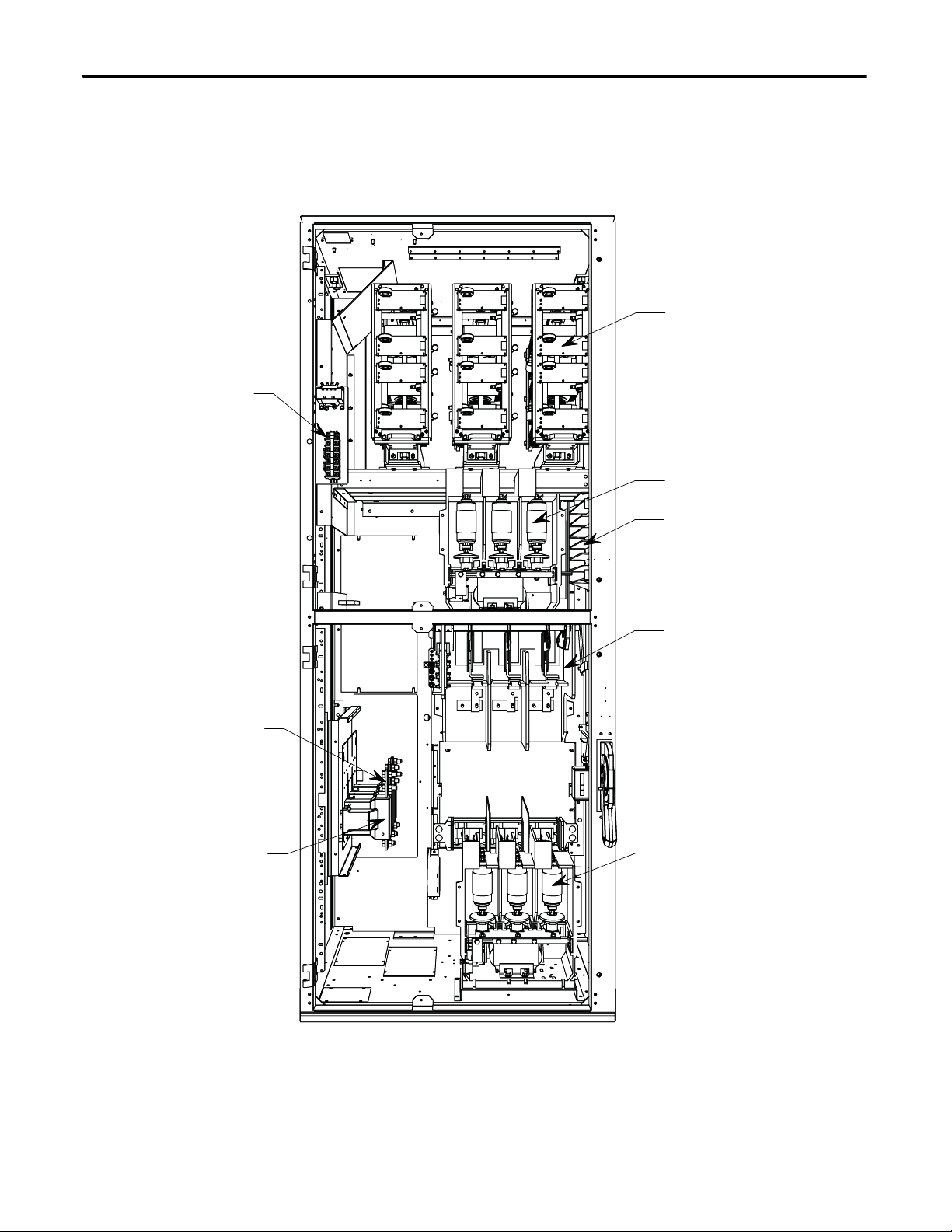
Chapter 2 Installation
Terminal Block
Assembly
Load Cable
Connection Point
(top exit)
Power Stack A ssembl y
Bypass Vacuum Contactor
Voltage Sensing Module
Non Load Break
Isolation Switch
Line Vacuum Contactor
Current Transformers
Bulletin 1562E
Figure 28 - Cabinet Layout • 1562E – 180/360A, 2400V to 4160V (with LV panels not shown) (Non arc-resistant cabinet shown)
44 Rockwell Automation Publication 1560E-UM051F-EN-P - June 2013
Page 55

Installation Chapter 2
Power Cable Lugs
Ground Bus Lug
Cable Duct Boot
Cable Duct Barrier
Motor Cable Terminals
Figure 29 - Incoming Line Cable Connections
(viewed from the rear with power bus access cover removed) (Non Arc-resistant cabinet shown)
Figure 30 - Bottom Cable Exit Configuration
(with LV panel swung open) (Non Arc-resistant cabinet shown)
Rockwell Automation Publication 1560E-UM051F-EN-P - June 2013 45
Page 56

Chapter 2 Installation
Phase 3
Power Stac k Assem bly
Voltage Sensing Module
Load Connections
(top exit shown)
Phase 1 (front)
through 3 (back)
Current Transfo rmers
Bypass Vacuum Contactor
Line Connections
Phase 1 (top)
through 3 (bottom)
Phase 2
Power Stack Assembly
Phase 1
Power Stac k Assembly
Bulletin 1560E
Figure 31 - Power Connections • 1560E – 180/360A, 2400 to 4160V (Not available in an Arc-resistant design)
46 Rockwell Automation Publication 1560E-UM051F-EN-P - June 2013
Page 57

Figure 32 - Power Connections • 1560E – 180/360A, 5500 to 6900V (Not available in an Arc-resistant design)
Voltage Sensing Module
Bypass Vacuum Contactor
Phase 1
Line Connections
Phase 1
Power Stac k Assembly
Phase 2
Power Stack Assembly
Phase 3
Power Stac k Assembly
Phase 2
Line Connections
Phase 3
Line Connections
Load Connect ions
(top exit shown)
Phase 1 (front)
through 3 (back)
Current Transformers
Installation Chapter 2
Rockwell Automation Publication 1560E-UM051F-EN-P - June 2013 47
Page 58

Chapter 2 Installation
Voltage Sensing Module
Bypass Vacuum Contactor
Phase 1
Line Connections
Phase 1
Power Stac k Assembly
Phase 2
Power Stack Assembly
Phase 3
Power Stac k Assem bly
Phase 2
Line Connections
Phase 3
Line Connections
Load Connections
(top exit shown)
Phase 1 (front)
through 3 (back)
Current Transformers
Figure 33 - Power Connections • 1560E – 600A, 2400 to 6900V (Not available in an Arc-resistant design)
48 Rockwell Automation Publication 1560E-UM051F-EN-P - June 2013
Page 59

Installation Chapter 2
IMPORTANT
IMPORTANT
For retrofit units (Bul. 1560E), the CEC and NEC require that branch-circuit
protection of the AC line input to the controller be provided by a circuit breaker
or motor starter. This function is included with a Bulletin 1562E.
The control and signal wires should be positioned at least six (6) inches
(150 mm) from power cables. Additional noise suppression practices (including
separate steel conduits for signal leads, etc.) are recommended.
Bulletin 1503E
For 1503E, refer to applicable documentation from OEM for installation,
grounding, interlocking and wiring. This manual should be utilized in
conjunction with the OEM supplied documentation, and is suitable for
commissioning, programming, calibration, metering, serial communications,
diagnostics, troubleshooting and maintenance of a standard solid-state controller.
Power Wiring
Interlocking
The wire sizes must be selected individually, observing all applicable safety and
CEC or NEC regulations. The minimum permissible wire size does not
necessarily result in the best operating economy. The minimum recommended
size for the wires between the controller and the motor is the same as that used if
a main voltage source connection to the motor was used. The distance between
the controller and motor may affect the size of the conductors used.
Consult the wiring diagrams and appropriate CEC or NEC regulations to
determine correct power wiring. If assistance is needed, contact your area
Rockwell Automation Sales Office.
Hinged doors and panels, which provide access to medium voltage components,
must be mechanically interlocked to ensure circuit isolation. If a combination
MV SMC Flex (1562E) is purchased from Rockwell Automation, all medium
voltage compartments will be mechanically interlocked such that they cannot be
opened unless the isolating switch for the unit is open. Each medium voltage
door is interlocked to the isolating switch handle. To open the doors, move the
isolating switch to the OFF position and loosen the two retaining bolts on the
main power cell door. Once this door is open, the other doors may be opened in
sequence, depending on the specific interlock scheme provided. The retrofit-type
MV SMC Flex (1560E) is intended to be added to an existing motor controller,
and has no isolating means included.
ATT EN TI ON : For 1503E and 1560E, it is the responsibility of the installer/user to
ensure the equipment interlocking scheme is in place and functional before
energizing the equipment. Inadequate interlocking could expose personnel to
energized parts which could result in severe burns, injury or death.
Rockwell Automation Publication 1560E-UM051F-EN-P - June 2013 49
Page 60

Chapter 2 Installation
TIP
TIP
IMPORTANT
Rockwell Automation can assist with the selection of an appropriate
interlocking method, which may include mechanical modifications to the
cabinet(s) or key-type lock systems.
An auxiliary cabinet may be attached to the main structure. It will be raminterlocked with the main power cell door, which will not allow it to be opened
until the main power cell door is opened.
Installation
Physical Location
The controller is designed for limited front access (components may have to be
removed) and should be installed with adequate and safe clearance to allow for
total door opening. The back of the unit may be placed against a wall and several
units may be set end to end. In special cases where floor space is limited and the
unit is not against a wall, certain cabinet sections may be placed back to back.
This requirement must be stated in the specifications in order to mechanically
alter the controller.
Fan
The controller may include a cooling fan which is used to cool the component. It
should be checked for free operation and no obstruction of the airflow.
Ground Bus Bar
Controllers which are delivered in two (or more) sections, or retrofit controllers,
will require that the ground bus bar (6 mm x 51 mm) [1/4 in. x 2 inches], which
runs the entire length of the equipment in the center back side, be reconnected. A
mechanical lug for #8-#10 AWG or #6-250 MCM cable is supplied at the
incoming end of the line-up. When the sections are brought together, bus links
are used to connect the bus bars.
Refer to 2-high, Series B drawings in Publication 1500-UM055_-EN-P for
power/ground bus connection.
Power and Control Wiring
Controllers consisting of two or more sections will require that the power and
control wiring be connected per the schematic drawings provided.
50 Rockwell Automation Publication 1560E-UM051F-EN-P - June 2013
Page 61

Installation Chapter 2
TIP
Control Cables
Control cable entry/exit should be located near the terminal blocks; customer’s
connections are to be routed along the empty side of the terminals. Nylon cable
tie loops are provided at the left, front corner of the cabinet to route control
cables safely behind the low voltage panel hinges. Cables should be routed so they
do not interfere with the swing of the low-voltage panels.
Fiber-Optic Cables
The small, gray, fiber-optic cables are fragile and must be protected during
installation from sharp bends and impact.
Power Factor Correction Capacitors
The controller can be installed on a system with power factor correction
capacitors. The capacitors must be located on the line side of the controller. This
is required to prevent damage to the SCRs in the MV SMC Flex controller. A
separate switching contactor is recommended to apply the capacitors only after
the bypass contactor has closed, and to remove them when the bypass contactor
opens. See Figure 34
for two different acceptable connection methods.
Consult the factory if there are any capacitors on the same branch circuit as the
MV SMC Flex.
When discharged, a capacitor has essentially zero impedance. For switching,
sufficient impedance should be connected in series with the capacitor bank to
limit the inrush current. A method of limiting the surge current is to add
inductance in the capacitor conductors. This can be accomplished by putting
turns or coils of wire in the power connections to the capacitors (6-inch diameter
coil, six loops). For more information, refer to NEMA standard ICS 2, Part 2,
Capacitor Applications.
Care should be used in mounting the coils so that they are not stacked directly on
top of each other or they will have a cancelling effect. Also, the coils should be
mounted on insulated supports away from metal parts so they will not act like
induction heaters.
ATT EN TI ON : Any covers or barriers removed during installation must be
replaced and securely fastened before energizing equipment. Failure to do so
may result in severe burns, injury or death.
Rockwell Automation Publication 1560E-UM051F-EN-P - June 2013 51
Page 62

Chapter 2 Installation
Bypass
Contac tor
di/dt Inductor
PFCC
Contac tor
Fuse
Isolation Switch
Power Bus
Isolation Switch
Fuse
Isolation Contactor
di/dt Inductor
PFCC
(Power Factor
Correction Capacitor)
Contactor
Capacitor
Motor
Figure 34 - Typical One-Line Diagram
(Showing 2 Different Styles of Power Factor Capacitor Connections)
Surge Arrestor Protection Devices
Rockwell Automation highly recommends that motor surge capacitors and/or
motor surge arresters not be located on the load side of the SMC. The issues that
warrant this are:
• Motor and system inductance limits the rate at which the current can
change through the SMC. If capacitance is added at the motor, the
inductance is negated. The surge capacitors downstream of the SMC
represent a near zero impedance when presented with a step voltage from
the turn on of the SCRs near the line voltage peak. This causes a high level
of di/dt to occur, due to the fact that the motor cables are generally short
in length. There is very little impedance between the capacitor and SCR to
limit the di/dt of this capacitor charging current. This can result in damage
to the power semiconductors (SCRs) in the SMC.
• It is essential to understand the clamping voltage of the arresters and type
of grounding used in the distribution system. The switching of the SCRs
generates slightly higher than nominal peak line to ground voltages. The
typical peaks are 1.5 times the nominal line to ground peak voltages. These
may cause the arresters to conduct, which could affect the operation of the
SMC and result in faults. Depending upon the instance at which the
arresters conduct, this could also result in SCR damage.
52 Rockwell Automation Publication 1560E-UM051F-EN-P - June 2013
Page 63

Installation Chapter 2
• The capacitance in combination with the line and motor impedance could
also be excited by the voltage steps from SCR switching to create resonant
voltage swings which could exceed the device voltage withstanding ratings
or surge arrester rating, or cause distorted voltage signals which may be
misinterpreted by the MV SMC Flex control system.
Motor Overload Protection
Thermal motor overload protection is provided as standard (though it must be
programmed) with the MV SMC Flex controller. If the overload trip class is less
than the acceleration time of the motor, nuisance tripping may occur.
ATT EN TI ON : Overload protection should be properly coordinated with the
motor to avoid damage to equipment.
Two special applications require consideration: Two-speed Motors, and Multimotor Protection.
Two-speed Motors
The MV SMC Flex controller has overload protection available for single speed
motors. When the MV SMC Flex controller is applied to a two-speed motor, the
Overload Class parameter must be programmed to OFF, and separate overload
relays must be provided for each speed.
Multi-motor Protection
The MV SMC Flex controller provides overload protection for only one motor.
When the MV SMC Flex is controlling more than one motor, the Overload Class
Parameter must be programmed to OFF, and individual overload protection is
required for each motor.
Rockwell Automation Publication 1560E-UM051F-EN-P - June 2013 53
Page 64

Chapter 2 Installation
EMC Compliance
ATT EN TI ON : This product has been designed for Class A equipment. Use of the
product in domestic environments may cause radio interference, in which case,
the installer may need to employ additional mitigation methods.
The following guidelines are provided for EMC installation compliance.
Enclosure
Install the product in a grounded metal enclosure.
Wiring
Wire in an industrial control application can be divided into three groups: power,
control, and signal. The following recommendations for physical separation
between these groups is provided to reduce the coupling effect.
• Different wire groups should cross at 90° inside an enclosure.
• Minimum spacing between different wire groups in the same tray should
be 16 cm (6 in.).
• Wire runs outside an enclosure should be run in conduit or have shielding/
armor with equivalent attenuation.
• Different wire groups should be run in separate conduits.
• Minimum spacing between conduits containing different wire groups
should be 8 cm (3 in.).
• For additional guidelines, please refer to Wiring and Ground guidelines,
publication DRIVES-IN001A-EN-P.
• Wire earth ground to control terminal 14.
• Use shielded wire for: PTC Input
Tac h In pu t
Ground Fault Input
• Terminate shielded wires to terminal 14.
• Ground fault CT must be inside or within 3 m of metal enclosure.
54 Rockwell Automation Publication 1560E-UM051F-EN-P - June 2013
Page 65

Installation Chapter 2
• To meet produce susceptibility requirements, ferrite cores need to be
added to the communication lines. All cores specified below are the split
core type, so they can be added to existing connections.
– When using an external HIM (or DPI interface), a core should be
added to the HIM cable near the SMC Flex control module. The
recommended core is Fair-Rite no. 0431167281 or equivalent.
– When using DeviceNet, two cores need to be added to the DeviceNet
cable near the SMC Flex control module. The recommended cores are
TDK ZCAT2033 0930H and TDK ZCAT2035 0930 or equivalent.
Control Power
Control Voltage
The SMC Flex controller will accept a control power input of 100 to 240V AC,
(-15 / +10%), 1 phase, 50/60 Hz. Refer to the product nameplate to verify the
control power input voltage.
Connect control power to the controller at terminals 11 and 12. The control
power requirement for the control module is 75 VA. Depending on the specific
application, additional control circuit transformer VA capacity may be required.
Control Wiring
Ta b l e 2 provides the control terminal wire capacity and the tightening torque
requirements. Each control terminal will accept a maximum of two wires.
Table 2 - Control Wiring and Tightening Torque
Wire Size Torque
0.75 to 2.5 mm (#18 to #14 AWG) 0.6 Nm (5 lb-in.)
Rockwell Automation Publication 1560E-UM051F-EN-P - June 2013 55
Page 66

Chapter 2 Installation
Control Terminal Designations
As shown in Figure 35, the SMC Flex controller contains 24 control terminals on
the front of the controller.
Figure 35 - SMC Flex Controller Control Terminals
Ter min al
Number
11 Control Power Input
12 Control Power Common
13 Control Enable Input
14 Control Module Ground 26 Tach Input (+)
15 Option Input #2
16 Option Input #1
17 Start Input
18 Stop Input
19 Aux. Contact #1 (Ext. Bypass)
20 Aux. Contact #1 (Ext. Bypass)
21 Not Used 33 Aux. Contact #4 (Normal)
22 Not Used 34 Aux. Contact #4 (Normal)
Description Terminal
Number
(1)
(1)
(2)
(1)(2)
(1)(2)
(1)(2)
(1)(2)
(1)(3)
(1)(3)
23 PTC Input
24 PTC Input
25 Tach Input (-)
27 Ground Fault Transformer Input
28 Ground Fault Transformer Input
29 Aux. Contact #2
30 Aux. Contact #2
31 Aux. Contact #3
32 Aux. Contact #3
Description
(2)
(2)
(2)
(2)
(1)
(1)
(1)
(1)
(1)(4)
(1)(4)
(1) RC snubbers are required on inductive loads connected to auxiliary.
(2) Do not connect any additional loads to these terminals. These “parasitic” loads may cause problems with operation, which may
result in false starting and stopping.
(3) Aux. Contact #1 is always programmed for Ext. Bypass (NO) to control the bypass contactor in MV applications.
(4) Aux Contact #4 is always programmed for “Normal” (NO) to control the isolation contactor in MV applications.
Note: The OFF state leakage current for a solid-state device connected to an SMC Flex input must be less than 6 mA.
56 Rockwell Automation Publication 1560E-UM051F-EN-P - June 2013
Page 67

Commissioning Procedure
Chapter 3
Preliminary Setup
A. Ensure the work area is clean and tidy. Pathways to main disconnect and
emergency stop push button must be clear and unobstructed.
B. The following test equipment is to be prepared for use:
• Test power supply, supplied with each controller
• Multimeters
• Hi-Pot Tester (recommended) or Megger
• Oscilloscope with memory (optional)
C. Complete drawing package and parts list.
D. Specification of project.
Rockwell Automation Publication 1560E-UM051F-EN-P - June 2013 57
Page 68

Chapter 3 Commissioning Procedure
System Characteristics
Job Name: _________________________________ Job Number: ____________________________________
Rated Voltage: ______________________________ Rated Current: ____________ S.F.: ________________
Actual Motor Load
Load Type: Fan ____ Pump____ Conveyor____ Compressor____ Mixer______
Other________________________________________________
Constant Torque_________ or Variable Torque ______________
Actual Motor Data: __________________________________________________
Motor HP: _________________________________________________________
Motor Rated Speed: __________________________________________________
Motor F.L.A.: _______________________________________________________
Motor S.F.: _________________________________________________________
Motor L.R.A.: ______________________________________________________
Frequency: ________________________________________________________
Phases: ___________________________________________________________
58 Rockwell Automation Publication 1560E-UM051F-EN-P - June 2013
Page 69

Commissioning Procedure Chapter 3
IMPORTANT COMMISSIONING CHECKS
ATT EN TI ON : When commissioning a MV SMC Flex, it is critical that following
important checks are completed. For more details, follow the commissioning
guidelines that follow this page.
• Inspect the equipment for any signs of physical damage.
• Verify SMC Flex physical installation is complete.
• Verify the integrity and operation of all safety interlocks.
• Verify that motor mechanical installation is complete.
• Verify that Incoming Power wiring to SMC Flex is complete and all
connections are tight.
• Verify that Motor cabling to SMC Flex is complete and that all
connections are tight.
• Verify that Control wiring to SMC Flex is complete.
• Check for any damaged components and verify that electrical clearances
have not been reduced while installing power cables.
• Verify Incoming Power System Grounding
(Floating/Solid-Ground/Resistive Ground) and determine if Vcom on the
interface board should be connected to a ground reference or not (refer
to Resistance Checks
• Check if there are any Power Factor Correction Capacitors (refer to Power
Factor Correction Capacitors on page 51 of Chapter 2 for correct
installation requirements of these capacitors).
• Check if Surge Capacitors and/or Surge Arrestors are installed at the
motor. Open motor junction box and verify it by yourself. These must be
disconnected from the circuit. (refer to Surge Arrestor Protection Devices
on page 52 of Chapter 2).
• Verify fiber-optic cables are connected at the right location (FO cables on
Phase-A power pole go to Phase-A on the Interface board, Phase-B of
power pole to Phase-B on the Interface board and Phase-C of power pole
to Phase-C on the interface board) and the connectors are fully seated in
their sockets.
on page 68).
• Verify that circuit board plug connectors are installed and fully inserted in
their sockets.
• Verify that the cooling fan (if supplied) is secured and the rotor is not
obstructed.
• Complete device resistance checks per user manual (refer to Resistance
Checks on page 68 of Chapter 3).
Rockwell Automation Publication 1560E-UM051F-EN-P - June 2013 59
Page 70

Chapter 3 Commissioning Procedure
IMPORTANT
• Complete Power Supply Tests (refer to Power Supply Tests on page 64 of
Chapter 3).
• Program the module with correct parameter settings.
• Start the unit and record scope waveforms (line voltage, motor voltage and
motor current).
Preliminary Check
ATT EN TI ON : Ensure that all sources of power are isolated and locked out before
working on installed equipment. Verify that all circuits are voltage free using a
hot stick or appropriate voltage measuring device. Failure to do so may result in
severe burns, injury or death.
A. Verify correct power cable phase sequencing, and that connections are
tight.
B. Verify power fuse ratings and condition.
C. Verify control fuse ratings and condition.
D. Check that power cable installation has not damaged components, and
that electrical spacings have not been reduced.
E. Check that fiber-optic cables are fully seated in their connectors.
F. Check that circuit board plug connectors are installed and fully inserted in
their sockets.
G. Check that the cooling fan (if supplied) is secured and the rotor is not
obstructed.
H. Verify integrity and operation of all interlocks.
I. In the case of the 1503E, verify wiring and perform all tests in conjunction
with OEM documentation.
Programming
60 Rockwell Automation Publication 1560E-UM051F-EN-P - June 2013
MV SMC Flex Module
Refer to Chapter 4 for programming procedures.
The default (factory) parameter settings are as shown in Appendix B
Settings may be different on engineered orders, or when option modules or
customer requirements dictate different settings.
The module should be programmed with an understanding of how the SMC
functions, and the characteristics of the motor and driven load. Inappropriate
settings may elicit unexpected results such as lack of acceleration torque or
full-voltage starting. For Pump Control applications, refer to Pump Application
Considerations on page 20 of Chapter 1.
.
Page 71

Commissioning Procedure Chapter 3
If the factory settings are not suitable for the application, program the module to
meet the application requirements. Contact your local Rockwell Automation
representative or the factory if assistance is required.
Hi-Pot and Megger Test
It is recommended that insulation levels be checked before energizing power
equipment. This may be done with a High Voltage AC insulation tester
(HI-POT) or a Megger. See Vacuum Contactor User Manual for suggested
HI-POT testers, and for test procedures for vacuum contactors. If using a
Megger, a 5000 volt type is recommended.
ATT EN TI ON : Solid-state devices can be destroyed by high voltage. Use jumper
wires between heatsinks to short out the SCRs before applying high test
voltages to the power circuit. Disconnect the white wires (L1, T1, L2, T2, L3, T3)
from the voltage sensing board and remove the plug connector. If voltage
transformers are present, remove one primary fuse from each device. On the
1503E, consult OEM documentation for location of voltage sensing board.
ATT EN TI ON : Use caution when performing the HI-POT or Megger Test. High
voltage testing is potentially hazardous and may cause severe burns, injury or
death. Where appropriate, the case of the test equipment should be connected
to ground.
Insulation may be tested from phase to phase and phase to ground. The
recommended level for AC HI-POT testing is (2 X VLL) Volts, where VLL is the
rated line-to-line voltage of the power system. The leakage current may be
recorded for future comparison testing, and must be less than 20 mA.
If a Megger is used, it should indicate 50 k megohms or greater if it is isolated as
explained in the next paragraph. If the motor is connected, the Megger should
indicate 5 k megohms or greater.
If a 1560E is being tested, it is recommended that the input and output cables be
disconnected for each phase. If a 1562E is being tested, it is recommended that
the main contactor be in the open position, and that the output cables be
disconnected for each phase. (See points marked with an asterisk * in Figure 36
This will ensure the unit is isolated from the line and the motor. The line and the
motor may be tested separately to locate problem areas. If a 1503E is being tested,
consult OEM documentation.
After completing the test, remove all semiconductor jumpers and test the devices
with a multimeter to ensure no damage has occurred from the insulation test.
Reconnect the system as it existed prior to this section. Perform the power supply
and resistance checks in the following sections.
ATT EN TI ON : Failure to reconnect all wires and cables correctly may result in
equipment damage, personal injury or death.
Rockwell Automation Publication 1560E-UM051F-EN-P - June 2013 61
)
Page 72

Chapter 3 Commissioning Procedure
654321
TO C.T.'S
TO SMC F lex
MODULE
POWER
OUT
CT INPUTS
J3
A-
A+
B-
B+
C-
C+
TB5
TB6
GDPS
SMC Flex INTERFACE BOARD
VBS
TB21
GATE TRANSMITTERS
PHASE A
Vcom
PHASE B PHASE C
TX1
TX2
TX3
TX4
TX5
TX6
TX7
TX8
TX9
TX10
TX11
TX12
TX13
TX14
TX15
TX16
TX17
TX18
POWER
IN
TB1
U16
U18
U20
L1
L2/N
G
115/230V AC
FIBRE OPTIC CABLES
HS1
G1C1G1
C1
HS2
G2
C2
HS3
G1C1G3
C3
HS4
G4
C4
HS5
G5
C5
HS6
G6
C6
HS7
LINE
LOAD
THERMISTOR
RR1
RR2
RR3
C2
C1
C5
OV2
OV3
C3
OV1
OV4
C4
OV5
OV6
C6
GATE DRIVER BOARDS
RX1 TX1 GD1
G1
C1
OV1
S1
C1
S
C
RX1 TX1
GD3
G3
C3
OV3
S3
C3
S
C
RX1 TX1
GD4
G4
C4
OV4
S
C
S4
C4
RX1 TX1 GD5
G5
C5
OV5
S
C
S5
C5
C5
RX1 TX1
GD6
G6
C6
OV6
S
C
S6
T1
C6
THERMISTOR
RX1 TX1
GD2
G2
C2
OV2
S2L1C2
S
C
T
RS1 RS2
CS1 CS2
RS3
CS3
PH
A
SE B PHASE C
CURRENT LOOP CT
CURRENT LOOP
TRANSFORMER
115/230V AC
50/60Hz
H1
H3
H2
H4
X1
X2
VOLTAGE SENSING BOARD
GND2 GND1 J1
T3 L3
T2 L2
T1 L1
TEMP.
Figure 36 - Typical MV SMC Flex Power System Wiring Diagram (5500/6900V shown)
62 Rockwell Automation Publication 1560E-UM051F-EN-P - June 2013
Page 73

Figure 37 - Connection and Test Information for Interface Board
+5 +15
C
C
C
C
C
C
B
B
B
B
B
B
A
A
A
A
A
A
ROCKWELL
AUTOMATION
SW2: When ON (up) provides
test pulses to gate driver circuits.
NOTE: Must be OFF (down) for
normal operation.
LED (Red): ON when
test pulses on
SMC Flex control module
Ribbon connec tors to connect
to SMC Flex control module
(underneath control module)
Current
feedback
test points
Ribbon connector
to Voltage
Sensing Board
TB5:
Curren t
transformer
connections
LED (Green):
ON when
power is
present
LED (Green):
ON when current
loop power
supply is present
Module common:
Do not connect to
this terminal.
Volt age
feedback
test points
Current loop
power supply
sensor input
LED (Yellow): ON
when Phase C
gate signal active
TP18, 19, 20:
Power supply test
points.
LED (Green): ON when signal present
at temperature feedback fibre optic
receiver s
TP15: Common for
Gate/Pulse TPs
TP13: Phase C
gate signal
TP11: Phase B
gate signal
LED (Yellow): ON
when Phase B
gate signal active
TP11: Phase B
gate signal
TP8: Common for
Gate/Pulse TPs
TP4: Phase A
gate signal
LED (Yellow): ON
when Phase A
gate signal active
Phase A
Fibre Optic
Transmitters send
gate signals to
driver boards
Phase B
Fibre Optic
Transmitters
Phase C
Fibre Optic
Transmitters
Temperature
Feedba ck
Fibre Optic
Receivers
Temp A
Temp B
Temp C
L N G
Control Power
110-240 VAC
L N
Power out to
SMC Flex
Serial
Number
Replacement
Part Number
SW3: Used to
detect temp erature
feedback channels
TEMP
DEFEAT
Notes: 1. ICOM is the common connection for Gate and Pulse test points.
2. VCOM is the common connection for Current and Voltage feedback test points. Do not connect J2 (VCOM) to earth
ground; do not connect ICOM and VCOM together, either directly or through test probes, meter or scope common.
ICOM
GATE
PULSE
GATE
PULSE
GATE
PULSE
ICOM
VCOM
TB21
I-A
I-B
I-C
LINE A
LOAD A
LINE B
LOAD B
LINE C
LOAD C
VCOM
TB6
J2
TB5
A-
A+
B-
C-
C+
B+
VCOM
Commissioning Procedure Chapter 3
Rockwell Automation Publication 1560E-UM051F-EN-P - June 2013 63
Page 74

Chapter 3 Commissioning Procedure
SW2 – Close (slide up) to initiate test pulses Red LED – ON when test pulses ac tive
D1
SW2
Power Supply Tests
ATT EN TI ON : Servicing energized industrial control equipment can be
hazardous. Severe injury or death can result from electrical shock, burn, or
unintended actuation of controlled equipment. Before proceeding, ensure that
all sources of power are isolated and locked out. Verify that all circuits are
voltage free using a hot stick or appropriate voltage measuring device. Any
covers or barriers removed during this procedure must be replaced and securely
fastened before energizing equipment. Where appropriate, the case of test
equipment should be connected to ground.
1. Isolate incoming power.
2. Open the door(s) providing access to the SCR/heatsink assemblies. You
will be touching components which are connected to the high voltage
power circuit, so be sure to isolate power as stated above.
3. Apply rated control voltage to the control circuits from a separate control
source, or by plugging into the test source connector, and selecting the
TEST position of the control switch.
4. Check voltage on each gate driver board by connecting a DC voltmeter at
TP4(+) and TP3(-). (See Figure 39
.) The voltage should be 18 - 22V DC.
5. Locate the SMC Flex Interface board in the control section (See Figure 37
and Figure 38
). This circuit board has the control module mounted on it.
Locate the switch labeled SW2 at the upper left corner of the board. Close
the switch by sliding the toggle up. This starts a pulse generator to supply
simulated gate-pulse signals via fiber optic cables to the gate driver boards.
A red LED beside the switch, and the three yellow LEDs on the left side of
the Interface board should be lit. (Note: They may appear dim, depending
on ambient light conditions).
Figure 38 - Interface PCB
64 Rockwell Automation Publication 1560E-UM051F-EN-P - June 2013
Page 75

Commissioning Procedure Chapter 3
Tem pera tur e si gn al
fiber-optic transmitter
Gate signal
fiber-optic receiver
Plug-in test
power supply
Current loop CT
Snubber
terminal
Cathode
terminal
Common
test point
+20V test point
+5V test point
Yellow LED
Thermistor
connector
Gate signal
test point
Overvoltage
sense terminal
J3
J4
J1
TP3 TP4
TP2
TP1
J2
RX2RX1
J6
6. With the gate pulses on, check the voltage again on each gate driver board
as described in Step 4 above. The voltage should be 4 - 5V DC.
7. Locate the Portable Test Power Supply that was included with the
equipment, and verify that the rating corresponds to the available power
system (i.e. 110/120 VAC or 220/240 VAC). Plug the unit into the power
source, and plug the green connector into J1 on each of the gate driver
boards (see Figure 39
Figure 39 - Test Power Application on Gate Driver Board
.
8. The yellow LED on the upper right-hand side of the energized gate driver
circuit should be lit (it may appear dim, depending on ambient light
conditions). While the gate pulses are still on, check the voltage on each
gate driver board as described in step 4 above. The voltage should be
10-12V DC. If the voltage is less than 5V, then you have a bad gate drive
board. Do not leave the Portable Test Power Supply connected to a bad
gate driver board. The power supply adapter will burn up if the gate driver
board is shorted.
9. A more detailed check is performed by verifying the actual gate pulses by
connecting an oscilloscope between TP1 and TP3 (-) (see Figure 39
check gate pulses, the pulse generator must be enabled (i.e. SW2 toggled
up) and the Portable Test Power Supply should be connected to J1. The
pulse should appear as shown in Figure 40
). To
and Figure 41.
Rockwell Automation Publication 1560E-UM051F-EN-P - June 2013 65
Page 76

Chapter 3 Commissioning Procedure
Microseconds
Volt s
-2.0 -1.5 -1.0 -0.5 0.0 0.5 1.0 1.5 2.0 2.5 3.0----
Milliseconds
Figure 40 - Gate Pulse Detail – Typical SCR (ABB)
Figure 41 - Gate Pulse Test Waveform
10. If no pulse is observed, and the yellow LED is lit, check for a shorted gate
on the SCR by removing the green plug and connecting an ohmmeter to
the gate leads. If the LED is not lit, and the circuit voltage is as specified in
step 8 (above), pinch the tab on the blue fiber-optic connector and
carefully pull it straight out of the receiver. The end of the connector
should glow red to indicate the presence of a gate signal.
If it does not, remove the other end of the cable from the interface board
and check that the gray transmitter is emitting red light. If it is, the
fiber-optic cable must be replaced. If it isn’t, the interface board should be
replaced.
11. When each gate driver circuit has been checked, disconnect the power
supply and remove it from the cabinet.
ATT EN TI ON : The gate-drive circuits operate at high voltage when the SMC is
energized. Failure to remove the portable test power supply will result in
equipment damage and may cause severe injury or death.
66 Rockwell Automation Publication 1560E-UM051F-EN-P - June 2013
Page 77

Commissioning Procedure Chapter 3
12. Open the switch SW2 on the interface board (see Figure 38) before
returning the unit to service. Ensure the red LED is off.
ATT EN TI ON : If the SW2 switch is not in the open position when the SMC is
energized, the motor will start in an uncontrolled manner and may cause severe
damage.
13. Check that all plugs and connectors are secure. Retrieve all hardware and
tools from the equipment. Replace and secure any barriers removed during
servicing and close all doors before applying power.
Control Function Tests
ATT EN TI ON : Servicing energized industrial control equipment can be
hazardous. Severe injury or death can result from electrical shock, burn, or
unintended actuation of controlled equipment. Recommended practice is to
disconnect and lock out control equipment from power sources, and allow any
stored energy in capacitors to dissipate. The safety related work practices of
NFPA 70E, Electrical Safety Requirements for Employee Workplaces, must be
followed if it is necessary to work in the vicinity of energized equipment.
1. Apply rated control voltage to the control circuit.
2. Using the control schematic, apply control signals to cause relays and
contactors to energize, to verify operation.
3. Remove any jumpers used in the test and restore all circuits to normal
when finished.
Rockwell Automation Publication 1560E-UM051F-EN-P - June 2013 67
Page 78

Chapter 3 Commissioning Procedure
Resistance Checks
To ensure that resistors and connections have not been damaged during shipment
and installation, the following resistance tests should be performed before
energizing the starter.
1. Remove all power from the equipment.
ATTENTION: Verify that all circuits are voltage free using a hot stick or
appropriate voltage measuring device. Severe injury or death can result
from electrical shock, burn, or unintended actuation of controlled
equipment.
2. Measure DC resistance per the following chart:
Table 3 - Power Circuit Resistance Measurements
Location of Probes 1000V 1300V 1500V 2300V 3300V 4160V 5500V 6900V
Cathode to Cathode (KOhms)
Cathode to Cathode (KOhms)
Cathode to Gate (Ohms) 10-40 10-40 10-40 10-40 10-40 10-40 10-40 10-40
(1) Measured between terminals “Cathode” on CLGO Boards, upper two or between two within a phase.
(2) Measured between terminals “Cathode” on CLGO Boards, top to bottom within a phase.
(3) Measured between line and load terminals within a phase.
(1)
----22-3023-3121-2924-32
(2)
17-23 19-25 20-27 21-29 40-53 43-57 60-90
(3)
64-84
(3)
Voltage Sensing Module
3. If abnormal readings are obtained, refer to Power Circuit Troubleshooting
on page 123 of Chapter 9.
The voltage-sensing module consists of a voltage sensing board and mounting
plate (refer to Figure 48 on page 120
). The voltage sensing board has six
independent channels, with different sized resistors base on voltage range, which
convert voltages up to 10800V (7.2 kV @ 1.5 pu) down to low voltage levels
which can be used by the SMC Flex control logic.
Ta b l e 4
shows the input voltage ranges for each of the input terminals on the
voltage-sensing module. This module has been designed to operate at a nominal
input voltage of up to 7200V with a continuous 40% overvoltage. The output
voltages are scaled to provide close to 10V peak for a 140% input voltage at the
high end of each of the voltage ranges.
68 Rockwell Automation Publication 1560E-UM051F-EN-P - June 2013
Page 79

Commissioning Procedure Chapter 3
Software will be used to scale the output to show the correct value on the SMC
Flex front panel display. (See Parameter #106 – MV Ratio)
Table 4 - Input Voltage Ranges
Module Rated Voltage Voltage Range MV Ratio
1500 800-1500 1200
2500 1501-2500 580
4800 2501-4800 324
7200 4801-7200 195
The MV ratios shown above are nominal values and may be fine tuned to achieve
better accuracy on the display of the SMC Flex control module. While running
the motor in bypass mode, compare the voltage displayed on the control module
to a known accurate meter connected to the same source voltage as the motor the
MV SMC Flex is controlling. Parameter 106, MV Ratio, may be changed up or
down to match the Flex display to the external meter. A small change in ratio can
make a large change in the display, so 5 units at a time is recommended.
Increasing the ratio will decrease the displayed voltage, and visa versa.
Start-Up
1. Remove any temporary jumpers or grounding devices used during
commissioning.
2. Check that all tools are removed from the equipment. Any tools or
hardware used or dropped during installation and commissioning must be
retrieved and accounted for.
3. Check that all barriers or covers removed during installation or
commissioning have been securely mounted.
4. Close and secure all doors, and verify function of all interlocks that
prevent access to medium voltage compartments when the unit is
energized.
5. The controller is ready to power the motor.
Rockwell Automation Publication 1560E-UM051F-EN-P - June 2013 69
Page 80

Chapter 3 Commissioning Procedure
Notes:
70 Rockwell Automation Publication 1560E-UM051F-EN-P - June 2013
Page 81

Programming
TIP
TIP
Sel
Esc
Sel
Sel
Chapter 4
Overview
Keypad Description
This chapter provides a basic understanding of the programming keypad built
into the SMC Flex controller. This chapter also describes programming the
controller by modifying the parameters.
This User Manual pertains to SMC Flex control modules with version 4.xx
firmware (or later).
The keys found on the front of the SMC Flex controller are described in Ta b l e 5 .
Table 5 - Keypad Descriptions
Escape Exit a menu, cancel a change to a parameter value, or
Select Select a digit, select a bit, or enter edit mode in a parameter
Up/Down Arrows Scroll through options increase/decrease a value, or toggle a bit.
Enter Enter a menu, enter edit mode in a parameter screen, or save a
acknowledge a fault/alarm.
screen.
change to a parameter value.
For ease of programming values, after using the Enter key to edit, use the Sel
key to jump to the digit that needs to be modified, then use the arrow keys to
scroll through the digits.
Programming Menu
Parameters are organized in a three-level menu structure for straightforward
programming. Figure 42
details the programming menu structure and the three-
level hierarchy.
In order to change parameters, the controller must be in the STOP mode, and the
control voltage must be present.
Rockwell Automation Publication 1560E-UM051F-EN-P - June 2013 71
Page 82

Chapter 4 Programming
Select language
being deployed
Power-up and
Status Display
Lang
or or or or
Choose Mode
or
OPERATION LEVEL
Memory
Storage
Preferences Diagnostics
Log
In
(3)
Device SelectParameter
Monitoring
Set Up
Motor Protection
Communications
Utility
Linear List
SMC Flex Reset to Defaults
Save to EEPROM
Recall EEPROM
Change Password
User Dspl Line
User Dspl Time
User Dspl Video
Reset User Display
Alarms
Fau lts
Device Revision
Parameter menu
continued in Fi gure 43
MAIN MENU
(1)
GROUP MENU
Esc
Esc
Esc
Sel
(1) The SMC Flex controller does not support EEPROM, Link, Process or Start-up modes.
(2) Steps back one level.
(3) Shown if password protection is configured
(2)
(2)
Figure 42 - Menu Structure Hierarchy
72 Rockwell Automation Publication 1560E-UM051F-EN-P - June 2013
Page 83
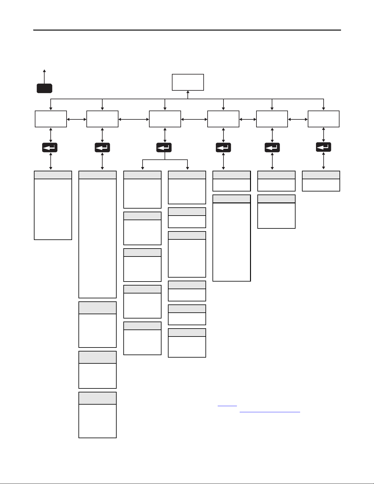
Motor
Protection
Communications Utility
Set Up
Monitoring
Metering
Volt s Phas e A-B
Volt s Phas e B-C
Volt s Phas e C-A
Current Phase A
Current Phase B
Current Phase C
Watt M eter
Megawatt Hours
Elapsed Time
Meter Reset
Power Factor
Mtr Therm Usage
Motor Speed
Esc
Linear List
Parame ter
(1),(3)
Basic
SMC Option
Motor Connection
Line Voltage
MV Ratio
Starting M ode
Ramp Time
Initial Torque
Cur Lim it Lvl
Kickstart Time
Kickstart Lvl
Stop Input
Option 1 Input
Option 2 Input
Stop Mode
Stop Time
Braking Current
Overload Class
Service Factor
Motor FLC
CT Ratio
Overload Reset
Aux1 Config
Aux2 Config
Aux3 Config
Aux4 Config
Backspin Timer
Parameter Mgt. (4)
Dual Ramp (Option 2
Input = Dual Ramp)
Starting M ode 2
Ramp Time 2
Initial Torque 2
Cur Lim it Lvl 2
Kickstart Time 2
Kickstart Lvl 2
Parameter Mgt. (4)
Preset SS (Option 2
Input = Preset SS)
Slow Speed Sel
Slow Speed Dir
Slow Speed Acc
Slow Running Cur
Parameter Mgt. (4)
(Option 2 Input =
Accu-Stop)
Braking Current
Slow Speed Sel
Slow Speed Dir
Slow Accel Cur
Slow Running Cur
Stopping Current
Parameter Mgt. (4)
Overload
Overload Class
Service Factor
Motor FLC
Overload Reset
Overload A Lvl
Parameter Mgt. (4)
Underload
Underload F Lvl
Underload F Dly
Underload A Lvl
Underload A Dly
Parameter Mgt. (4)
Undervoltage
Undervolt F Lvl
Undervolt F Dly
Undervolt A Lvl
Undervolt A Dly
Parameter Mgt. (4)
Overvoltage
Overvolt F Lvl
Overvolt F Dly
Overvolt A Lvl
Overvolt A Dly
Parameter Mgt. (4)
Unbalance
Unbalance F Lvl
Unbalance F Dly
Unbalance A Lvl
Unbalance A Dly
Parameter Mgt. (4)
Jam
Jam F Lvl
Jam F Dly
Jam A Lvl
Jam A Dly
Parameter Mgt. (4)
Stall
Stall Dly
Parameter Mgt. (4)
Ground Fault
Gnd Flt Enable
Gnd Flt Lvl
Gnd Flt Dly
Gnd Flt Inh Time
Gnd Flt A Enable
Gnd Flt A Lvl
Gnd Flt A Dly
Parameter Mgt. (4)
PTC
PTC Enable
Parameter Mgt. (4)
Phase Reversal
Phase Reversal
Parameter Mgt. (4)
Restart
Starts Per Hour
Restart Attempts
Restart Dly
Parameter Mgt. (4)
Comm Masters
Logic Ma sk
Parame ter Mgt. (4)
Data Links
Data In A1
Data In A2
Data In B1
Data In B2
Data In C1
Data In C2
Data In D1
Data In D2
Data Out A1
Data Out A2
Data Out B1
Data Out B2
Data Out C1
Data Out C2
Data Out D1
Data Out D2
Parame ter Mgt. (4)
Language
Language
Parameter Mgt. (4)
Motor Data
Motor Flc
Motor ID
CT Ratio
MV Ratio
Parameter Mgt. (4)
Linear LIst
All parameters
Parame ter Mgt. (4)
(1) Depending upon SMC option selected, some parameters may not appear in product display.
(2) Steps back one level
(3) For further information on parameters, refer to Appendix B
.
(4) For further information on parameter management, refer to Parameter Management
on page 76.
(2)
Figure 43 - Menu Structure Hierarchy
Programming Chapter 4
Rockwell Automation Publication 1560E-UM051F-EN-P - June 2013 73
Page 84

Chapter 4 Programming
Table 6 - Parameter Linear List
(1)
Parameter No. Description Parameter No. Description Parameter No. Description
1 Volts Phase A-B 46 Motor FLC 91 Data In B2
2 Volts Phase B-C 47 Overload Reset 92 Data In C1
3 Volts Phase C-A 48 OL Shunt Time 93 Data In C2
4 Current Phase A 49 OL Trip Enable 94 Data In D1
5 Current Phase B 50 Overload A Lvl 95 Data In D2
6 Current Phase C 51 Underload F Lvl 96 Data Out A1
7 Watt Meter 52 Underload F Dly 97 Data Out A2
8 Kilowatt Hours 53 Underload A Lvl 98 Data Out B1
9 Elapsed Time 54 Underload A Dly 99 Data Out B2
10 Meter Reset 55 Undervolt F Lvl 100 Data Out C1
11 Power Factor 56 Undervolt F Dly 101 Data Out C2
12 Mtr Therm Usage 57 Undervolt A Lvl 102 Data Out D1
13 Motor Speed 58 Undervolt A Dly 103 Data Out D1
14 SMC Option 59 Overvolt F Lvl 104 Motor ID
15 Motor Connection
(2)
60 Overvolt F Dly 105 CT Ratio
16 Line Voltage 61 Overvolt A Lvl 106 MV Ratio
17 Starting Mode 62 Overvolt A Dly 107 Aux1 Config
18 Ramp Time 63 Unbalance F Lvl 108 Aux3 Config
19 Initial Torque 64 Unbalance F Dly 109 Aux4 Config
20 Cur Limit Level 65 Unbalance A Lvl 110 Aux2 Config
21 Reserved 66 Unbalance A Dly 111 Language
22 Kickstar t Time 67 Jam F Lvl 112 Timed Start
23 Kickstar t Level 68 Jam F Dly 113 I Shutoff Level
(2)
(2)
24 Option 2 Input 69 Jam A Lvl 114 UTS Level
25 Starting Mode 2 70 Jam A Dly 115 Parameter Mgmt
26 Ramp Time 2 71 Stall Delay 116 Backspin Timer
27 Initial Torque 2 72 Gnd Flt Enable 117 V Shutoff Level
28 Cur Limit Level 2 73 Gnd Flt Level 118 OL Reset Level
29 Reser ved 74 Gnd Flt Delay 119 Ambient Temp.
30 Kickstar t Time 2 75 Gnd Flt Inh Time 120 Notch Position
(2)
(2)
31 Kickstart Level 2 76 Gnd Flt A Enable 121 Notch – Maximum
32 Stop Mode 77 Gnd Flt A Lvl 122 Start Delay
33 Stop Time 78 Gnd Flt A Dly 123 Bypass Delay
34 Pump Pedestal
(1)
79 PTC Enable 124 Fault 1
(2)
35 Braking Current 80 Phase Reversal 125 Fault 2
36 Braking Time
(3)
81 Star ts Per Hour 126 Fault 3
37 Load Type 82 Restart Attempts 127 Fault 4
38 High Eff Brake 83 Restart Delay 128 Fault 5
39 Slow Speed Sel 84 Line Fault 129 Start Time E
40 Slow Speed Cur 85 Emergency Run 130 Start Time 2E
41 Slow Accel Cur 86 Current Loss 131 Stop Time E
42 Slow Running Cur 87 Logic Mask 132 Option 1 Input
43 Stopping Current 88 Data In A1 133 Stop Input
44 O verload Class 89 Data In A2 134 Elapsed Time 2
45 Service Factor 90 Data In B1
(1) Pump Control module only – see Troubleshooting section for guidance.
(2) Do not change these parameters from the default settings.
(3) Brake module only – Consult factory.
(2)
74 Rockwell Automation Publication 1560E-UM051F-EN-P - June 2013
Page 85
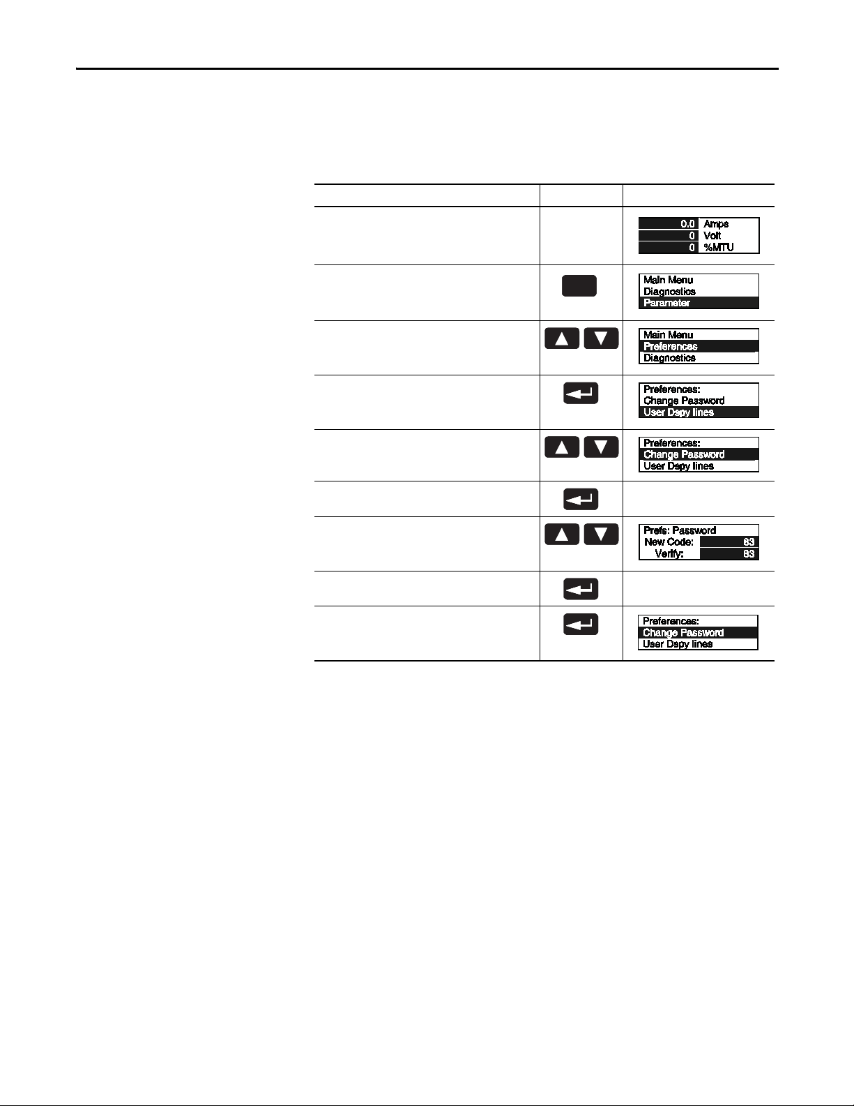
Programming Chapter 4
TIP
Sel
Esc
Password
The SMC Flex Controller allows the user to limit access to the programming
system through password protection. This feature is disabled with a factory-set
default of 0. To modify the password or login after a password is programmed,
complete the procedure below.
Description Action Display
––
1. Press the ESC key to go from the status display to the
Main menu.
2. Scroll with the Up/Down keys until the Preferences
option is highlighted.
3. Press the Enter key to access the Preferences menu.
4. Scroll with the Up/Down keys until the Change
Password option is highlighted.
5. Press the Enter key.
6. Press the Up/Down keys to enter the desired
number. If you are modifying the password, make a
note of it as displayed.
7. Verification of the new password is required. Press
the Enter key.
8. Press the Enter key after you have completed
modifying the password.
(1) To complete the programming process, re-enter the Main Menu mode to log out. This will eliminate unauthorized process to the
programming system.
(1)
If you lose or forget the password, contact your nearest Rockwell Automation
sales office. You can also call Rockwell Automation Medium Voltage Product
Support at 1-519-740-4790 for assistance.
Rockwell Automation Publication 1560E-UM051F-EN-P - June 2013 75
Page 86

Chapter 4 Programming
Esc Sel
EEPROM RAM ROM
Parameter Management
Before you begin programming, it is important to understand how the controller
memory is:
• structured within the SMC Flex controller
• used on power-up and during normal operation
Refer to Figure 44
Figure 44 - Memory Block Diagram
and explanations below.
Esc
Sel
Random Access Memory (RAM)
This is the work area of the controller after it is powered up. When you modify
parameters in the Setup mode, the new values are stored in RAM. When power is
applied to the controller, parameter values stored in the EEPROM are copied to
RAM. RAM is volatile and the values stored in this area are lost when the
controller is powered down.
Read-Only Memory (ROM)
The SMC Flex controller comes with factory default parameter values. These
settings are stored in nonvolatile ROM and are displayed the first time you enter
the Program mode.
76 Rockwell Automation Publication 1560E-UM051F-EN-P - June 2013
Page 87
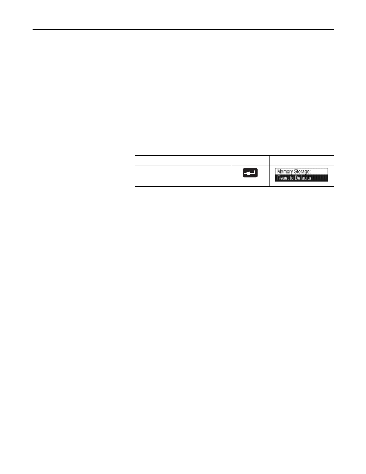
Programming Chapter 4
TIP
Electrically Erasable Programmable Read-Only Memory (EEPROM)
The SMC Flex controller provides a nonvolatile area for storing user-modified
parameter values in the EEPROM.
Using Parameter Management with DPI HIM
The SMC Flex will automatically save any parameter changes made during the
programming process.
Memory Storage and Parameter Management perform the same function of
resetting to defaults.
Description Action Display
Recalling Defaults
After parameter values have been modified, factory
default settings can still be re-initialized.
Rockwell Automation Publication 1560E-UM051F-EN-P - June 2013 77
Page 88
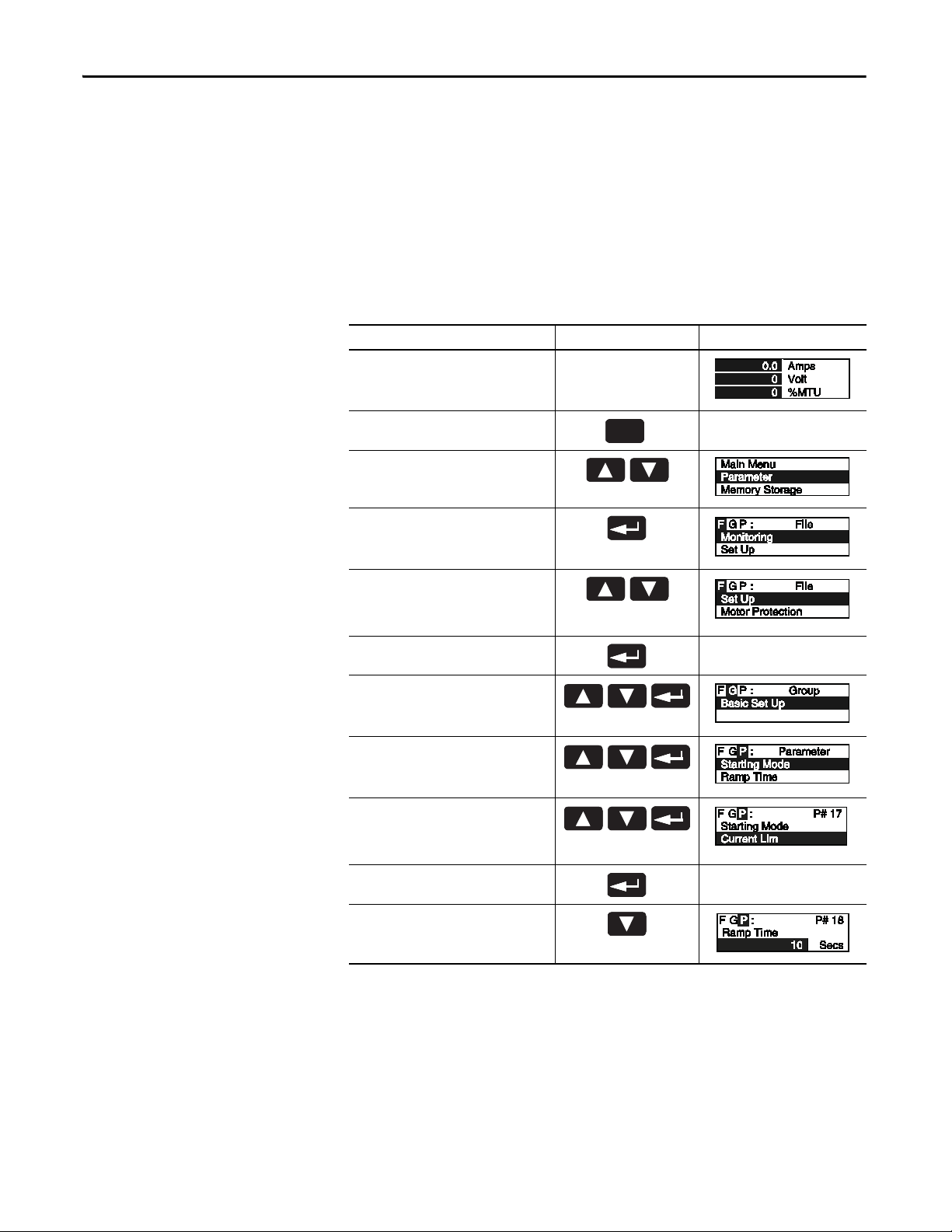
Chapter 4 Programming
Sel
Esc
Parameter Modification
All parameters are modified using the same method. The basic steps to
performing parameter modification are described below.
Notes:
1. Parameter values modified while the motor is operating are not valid until
the next start sequence begins.
2. If the password is set, parameters cannot be adjusted without logging in.
3. Use the Sel key to highlight a single digit.
Description Action Display
——
1. Press the ESC key to go from the status
display to the Main menu.
2. Scroll with the Up/Down keys until the
Preferences option is highlighted.
3. Press the Enter key to access the
Parameter menu.
(2)
—
4. Scroll with the Up/Down keys until the
option you want to use (Monitoring,
Motor Protection, etc.) is highlighted. For
this example, Set Up will be used.
5. Press Enter to select the Set Up group.
6. Scroll to Basic Set Up and press Enter.
7. Scroll to the Starting Mode parameter by
using the Up/Down keys, and press Enter.
8. Press Enter to select the option. Scroll to
the option of your choice by using the Up/
Down keys. For this example, we will
choose Current Limit.
9. Press the Enter key to accept the new
setting.
10.Scroll to the next parameter by using the
Down key. Continue the process until all
desired settings are entered.
(1) The SMC Option advises the user if any control opti on (i.e., Pum p Control) is resident. This parameter is factory set and cannot be
modified by the user.
(2) The display will indicate that the second line is now active by highlighting the first character. If the LCD display does not provide a
highlighted cursor, then the controller is in the Display mode.
(1)
—
—
78 Rockwell Automation Publication 1560E-UM051F-EN-P - June 2013
Page 89

Programming Chapter 4
Soft Start
The following parameters are specifically used to adjust the voltage ramp
supplied to the motor.
Parameter Option
Starting Mode
This must be programmed for Soft Start.
Ramp Time
Programs the time period that the controller will ramp the
output voltage up to full voltage from the initial Torque
level programmed.
Initial Torque
The initial reduced output voltage level for the voltage
ramp to the motor is established and adjusted with this
parameter.
Kickstart Time
A boost of current is provided to the motor for the
programmed time period.
Kickstart Level
Adjusts the amount of current applied to the motor
during the kickstart time.
(1) If the controller senses that the motor has reached full speed before completing the Soft Start, it will automatically switch to
(2) For ramp times greater than 30 s, set “Ramp Time” to zero and program “Ramp Time E” (parameter 129) to the new time. Do not
(1)
providing full voltage to the motor.
exceed the thermal capacity of the controller.
Soft Start
(2)
0 to 30 s
0 to 90% locked rotor torque
0.0 to 2.0 s
0 to 90% locked rotor torque
Current Limit Start
To apply a fixed, reduced-output voltage to the motor, the following parameters
are provided for user adjustment:
Parameter Option
Starting Mode
This must be programmed for Current Limit.
Ramp Time
Programs the time period that the controller will hold the
fixed, reduced output voltage before switching to full
voltage.
Current Limit Level
This parameter provides adjustability for the reduced
output voltage level provided to the motor.
Kickstart Time
A boost of current is provided to the motor for the
programmed time period.
Kickstart Level
Adjusts the amount of current applied to the motor
during the kickstart time.
(1) If the controller senses that the motor has reached full speed before completing the Soft Start, it will automatically switch to
(2) For ramp times greater than 30 s, set “Ramp Time” to zero and program “Ramp Time E” (parameter 129) to the new time. Do not
(1)
providing full voltage to the motor.
exceed the thermal capacity of the controller.
Current Limit
(2)
0 to 30 s
50 to 600% full load current
0.0 to 2.0 s
0 to 90% locked rotor torque
Rockwell Automation Publication 1560E-UM051F-EN-P - June 2013 79
Page 90

Chapter 4 Programming
Dual Ramp Start
The SMC Flex controller provides the user with the ability to select between two
Start settings. The parameters below are available in the Setup programming
mode. To obtain Dual Ramp control, Ramp #1 is located in the Basic Setup and
Ramp #2 is located in the Option 2 Input (Dual Ramp).
Parameter Option
Set Up
The user must select the Set-up programming mode to
obtain access to the Dual Ramp parameters.
Basic Set-up/Starting Mode
Set-up as stated in previous pages.
Option Input 2 (Dual Ramp)
This allows the user the option to choose between two
Soft Start profiles defined by:
1. Start Mode/Ramp Time/Initial Torque, and
2. Start Mode 2/Ramp Time 2/Initial Torque 2.
When this feature is turned on, the ramp time/initial
torque combination is determined by a hard contact input
to terminal 15. When this input signal is low, ramp time/
initial torque are selected. When input signal is high,
ramp time 2/initial torque 2 are selected. Once the Option
2 input has been set to Dual Ramp, you must ESC back to
the Parameter (File) menu. Re-enter into the Set Up
menu to show both Basic Set Up and Dual Ramp.
Basic Set Up/Start Mode
This selects the start mode for option #1.
Basic Set-up/Ramp Time
This programs the time period during which the controller
will ramp the output voltage up to full voltage for the first
Start set-up.
Basic Set-up/Initial Torque
This parameter establishes and adjusts the initial reduced
output voltage level for the first Soft Start set-up.
Dual Ramp/Start Mode 2
This selects the start motor for option #2.
Dual Ramp/Ramp Time 2
This programs the time period during which the controller
will ramp the output voltage up to full voltage for the
second Start set-up.
Dual Ramp/Initial Torque 2
The initial reduced output voltage level for the second
Start set-up is established and adjusted with this
parameter.
(1)
(2)
(2)
0 to 30 s
0 to 90% locked rotor torque
(3)
0 to 30 s
0 to 90% locked rotor torque
–
–
–
–
–
(1) The Dual Ramp feature is available on the standard controller.
(2) Kickstart can be programmed for both start modes.
(3) For ramp times greater than 30 s, set “Ramp Time 2” to zero and program “Start Time 2E” (parameter 130) for the new time. Do not
exceed the thermal capacity of the controller.
80 Rockwell Automation Publication 1560E-UM051F-EN-P - June 2013
Page 91

Programming Chapter 4
TIP
Full Voltage Start
Linear Speed
The SMC Flex controller may be programmed to provide a full voltage start
(output voltage to the motor reaches full voltage within 1/4 second) with the
following programming:
Parameter Option
Starting Mode
This must be programmed for Full Voltage.
Full Voltage
The SMC Flex provides the user the ability to control the motor speed during
starting and stopping maneuvers. A tach input is required as specified in Linear
Speed Acceleration and Deceleration on page 6 of Chapter 1.
Parameter Option
Starting Mode
This must be programmed for Linear Speed.
Ramp Time
Programs the time period that the controller will ramp
from 0 speed to full voltage.
Kickstart Time
A boost of current is provided to the motor for the
programmed time period.
Kickstart Level
Adjusts the amount of current applied to the motor
during the kickstart time.
(1)
Linear Speed
(1)
0 to 30 s
0.0 to 2.2 s
0 to 90% locked rotor torque
Stop Control
(1) For ramp times greater than 30 s, set “Ramp Time” to zero and program “Ramp Time E” (parameter 129) to the new time. Do not
exceed the thermal capacity of the controller.
The SMC Flex can be programmed to extend the motor stop time beyond the
normal coast-to-rest time. There are two standard stop modes: Soft Stop and
Linear Speed Deceleration.
Parameter Option
Stopping Mode This may be set to one of two
standard choices.
Stop Time Allows the user to set the time period
for the stopping function.
(1) Refer to Chapter 6 for optional stop control modes.
(2) A motor tachometer is required (refer to Linear Speed Ac celeration and Decelerat ion on page 6).
(3) Consult factory if settings over 30 seconds are required. The base rating of the MV SMC Flex is two starts (or one start/stop
combination) per hour, thirty seconds maximum for each operation. A stopping operation counts as a start for purposes of thermal
capacity calculations.
(1)
Soft Stop
Linear Speed
(3)
0 to 120 s
(2)
Options that control the stopping of the motor (Soft Stop, Pump Stop, Linear
Speed, Braking) require the self-powered gate drivers to be pre-charged by the
current loop power supply. If this supply is not present, an alarm symbol will
appear at the upper right corner of the control module display, and the options
will be inhibited. When the motor is stopped, it will coast. If the supply is
restored, the alarm symbol will be cleared and the module will perform the
programmed sequence.
Rockwell Automation Publication 1560E-UM051F-EN-P - June 2013 81
Page 92

Chapter 4 Programming
Preset Slow Speed
Basic Setup
This control mode may be configured to allow slow speed operation of the
motor.
Parameter Option
Slow Speed Select Allows the user to program the slow
speed that best fits the application.
Slow Speed Direction This parameter programs the slow
speed motor rotational direction.
Slow Accel Current Allows the user to program the
required current to a ccelerate the
motor to slow speed operation.
Slow Running Current Allows the user to program the
required current to operate the motor
at the slow speed setting.
Low: 7% – Forward
10% – Reverse
High: 15% – Forward
20% – Reverse
Forward, Reverse
0 to 450% of full load current
0 to 450% of full load current
The Basic Setup programming group provides a limited parameter set, allowing
quick start-up with minimal adjustments. If the user is planning to implement
some of the advanced features (i.e., Dual Ramp, Unbalance Level, etc.), then the
Linear List programming group should be selected. It provides all the Basic Setup
parameter set plus the advanced set.
Parameter Option
SMC Option
Displays the type of controller. This is factory set and not
adjustable.
Motor Connection
Displays the location of the SMC in relation to the motor
windings.
Line Voltage
Displays the system line voltage the unit is connected to.
MV Ratio
Scales the output from the Voltage Sensing Board to
display correct line voltage.
Starting Mode
Allows the user to program the SMC Flex controller for the
type of starting that best fits the application.
Ramp Time
This sets the time period during which the controller will
ramp the output voltage.
Initial Torque
The initial reduced voltage output level for the voltage
ramp is established and adjusted with this parameter.
Current Limit Level
The current limit level that is applied for the Ramp time
selected.
(1)
(2)
Standard
Line or Delta
–
1 to 10000
(Refer to Table 4 in Chapter 3
Soft Start, Current Limit, Full Voltage, Linear Speed
0 to 30 s
0 to 90% locked rotor torque
50 to 600% FLC
(3)
)
(1) Starting Mode must be programmed to Soft Start to obtain access to the Initial Torque parameter.
(2) Starting Mode must be programmed to Current Limit to obtain access to the Current Limit Level parameter.
(3) This is not to indicate how the motor windings are configured. Do not select “Delta” for MV applications.
82 Rockwell Automation Publication 1560E-UM051F-EN-P - June 2013
Page 93

Parameter Option
Kickstart Time
0.0 to 2.0 s
A boost current is provided to the motor for the
programmed time period.
Kickstart Level
0 to 90% of locked rotor torque
Adjust the amount of current applied to the motor during
kickstart.
Stop Input
Coast, Stop Option
Allows the user to select the operation of terminal 18,
Stop Input.
Option 1 Input
Disable, Stop Option, Fault, Fault NC, Network
Allows the user to select the operation of terminal 16,
Option Input #1.
Option 2 Input
Allows the user to select the operation of terminal 15,
Disable, Preset Slow Speed, Dual Ramp, Fault, Fault NC,
Network, Clear Fault, Emergency Run
Option Input #2.
Stop Mode
Soft Stop, Linear Speed
Allows the user to program the SMC Flex controller for the
type of stopping that best fits the application.
Stop Time
0.0 to 120 s
This sets the time period which the controller will ramp
the voltage during a stopping maneuver.
CT Ratio
1 to 1500
Scales the CT input to actual motor current (5 amp
secondary assumed). Example: CT Ratio = 150:5,
program 150
Aux1 Config
Contact is provided as standard with the SMC Flex
controller. This contact is located at terminals 19 and 20.
(1) (2)
Normal, Normal NC, Up-to-Speed, Up-to-Speed NC, Fault,
Fault NC, Alarm, Alarm NC, Network, Network NC, External
Bypass
Aux Contacts 1 allows the user to configure the operation
of the contacts.
Aux2 Config
Contact is provided as standard with the SMC Flex
controller. The contact is located at terminals 29 and 30.
Normal, Normal NC, Up-to-Speed, Up-to-Speed NC, Fault,
Fault NC, Alarm, Alarm NC, Network, Network NC, External
Bypass
Aux. Contacts 2 allows the user to configure the operation
of the contacts.
Aux3 Config
Contact is provided as standard with the SMC Flex
controller. The contact is located at terminals 31 and 32.
Normal, Normal NC, Up-to-Speed, Up-to-Speed NC, Fault,
Fault NC, Alarm, Alarm NC, Network, Network NC, External
Bypass
Aux. Contacts 3 allows the user to configure the operation
of the contacts.
Aux4 Config
Contact is provided as standard with the SMC Flex
controller. The contact is located at terminals 33 and 34.
(2)
Normal, Normal NC, Up-to-Speed, Up-to-Speed NC, Fault,
Fault NC, Alarm, Alarm NC, Network, Network NC, External
Bypass
Aux. Contacts 4 allows the user to configure the operation
of the contacts.
Parameter Mgmt
Ready, Load Default
Recall of factory default parameter values.
Programming Chapter 4
(3)
(1) Not accessible in MV applications for Firmware up to 5.001.
(2) Refer to I/O
(3) When programmed for ‘Emergency Run’ and the Option 2 input is energized, a ‘Start’ command will first close the bypass contactor,
on page 16 of Chapter 1 and Note: on page 18 of Chapter 1 for MV specific functionality.
then the line contactor for an across-the-line start of the motor. A ‘Stop’ command will open the line contactor first and allow the
motor to coast, regardless of the programmed ‘Stop Mode’. For Pump Option modules, the Option 2 input defaults to ‘Emergency
Run’ for MV applications.
Rockwell Automation Publication 1560E-UM051F-EN-P - June 2013 83
Page 94

Chapter 4 Programming
TIP
Motor Protection
While the Basic Setup group allows the user to get started with a minimum
number of parameters to modify, the Motor Protection group allows full access
to the SMC Flex controller’s powerful parameter set. Following is a listing of the
additional setup parameters provided.
The majority of parameters have a Fault and an Alarm setting.
Parameter Option
Overload
Allows the user to select the operation of the overload.
(1) (2)
(4)
(1) (2)
(1)
(1)
(1)
(3)
Underload
Determines the trip level as a percentage of the motor’s
FLA, and the delay period.
Undervoltage
Determines the trip level as a percentage of line voltage
and delay period.
Overvoltage
Determines the trip level as a percentage of line voltage
and delay period.
Unbalance
Allows the user to set the current unbalance trip level and
delay period.
Jam
Determines the trip level as a percentage of motor full
load current and delay period.
Stall
Allows the user to set the stall delay time.
Ground Fault
Allows the user to enable the ground fault level in amps,
delay time and inhibit time. A separate core balance
current transformer is required.
PTC
Allows the user to connect a PTC to the SMC and enable a
fault when it becomes active.
Phase Reversal
Determines the proper orientation of line connections to
the SMC. If Enabled and phases are out of sequence, a
fault will be indicated.
Restarts
Allows the user to determine the maximum number of
restarts per hour the unit can experience, and delay time
between consecutive starts.
Trip Class, Service Factor, Motor FLC, Overload Reset,
Overload Alarm Level
Underload Fault Level,
Underload Fault Delay,
Underload Alarm Level,
Underload Alarm Delay
Undervoltage Fault Level,
Undervoltage Fault Delay,
Undervoltage Alarm Level,
Undervoltage Alarm Delay
Overvoltage Fault Level,
Overvoltage Fault Delay,
Overvoltage Alarm Level,
Overvoltage Alarm Delay
Unbalance Fault Level,
Unbalance Fault Delay,
Unbalance Alarm Level,
Unbalance Alarm Delay
Jam Fault Level,
Jam Fault Delay,
Jam Alarm Level,
Jam Alarm Delay
Stall Delay
Ground Fault Enable,
Ground Fault Level,
Ground Fault Delay,
Ground Fault Inhibit Time,
Ground Fault Alarm Enable,
Ground Fault Alarm Level,
Ground Fault Alarm Delay
PTC Enable
Phase Reversal
Restarts Per Hour,
Restart Attempts,
Restart Delay
(1) The delay time must be set to a value greater than zero when Undervoltage, Overvoltage and Unbalance are enabled.
(2) For Jam and Underload detection to function, the Motor FLC must be programmed in the Motor Protection group. See Motor
Information on page 86.
(3) See details in Ground Fault on page 12.
(4) See details in Thermistor/PTC Protection on page 13.
84 Rockwell Automation Publication 1560E-UM051F-EN-P - June 2013
Page 95

Programming Chapter 4
Example Settings
Undervoltage
With Line Voltage programmed for 4160V and the Undervoltage level
programmed for 80%, the trip value is 3328V.
Overvoltage
With Line Voltage programmed for 3300V and the Overvoltage level
programmed for 115%, the trip value is 3795V.
(2)(3)
Jam
With Motor FLC programmed for 150 Amps and the Jam level programmed for
400%, the trip value is 600 Amps.
Underload
With Motor FLC programmed for 90 Amps and the Underload level
programmed for 60%, the trip value is 54 Amps.
(1)
(1)
(2)
(1) The average value of the three phase-to-phase voltages is utilized.
(2) The largest value of the three phase currents is utilized.
(3) The SMC Flex will self-protect.
Rockwell Automation Publication 1560E-UM051F-EN-P - June 2013 85
Page 96
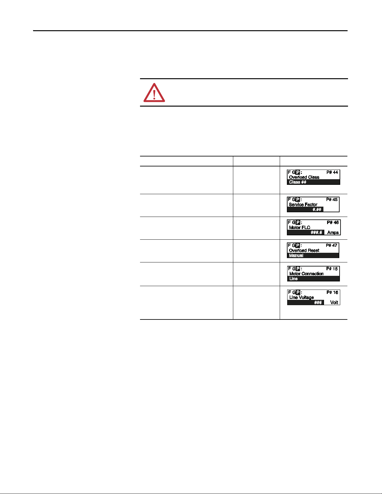
Chapter 4 Programming
Motor Information
The Basic Setup and Overload programming group allows the user to set
parameters indicating to the controller which motor is connected. It is important
to correctly input the data to achieve the best performance from your controller.
ATT EN TI ON : For overload protection, it is critical that the data be entered as it
appears on the motor nameplate.
Motor Data Entry
In the Program mode, enter the correct values into the Overload group:
Description Option Display
Overload Class
The factor default setting disables overload
protection. To enable it, enter the desired trip class
in this parameter.
Service Factor
Enter the value from the motor’s nameplate.
Motor FLC
Enter the value from the motor’s nameplate.
(1) (2)
(1) (2)
(1) (2) (3)
Disable, 10, 15, 20, 30
0.01 to 1.99
1.0 to 2200A
Overload Reset
Allows the user to select either a manual or auto
reset after an overload.
Motor Connection
Enter the type o f motor being connected to t he SMC
Flex: Line or Delta
Line Voltage
Enter the system voltage in this parameter. This
must be done to ensure optimum motor
performance and correct operation of undervoltage
and overvoltage protection.
(1) Found in Overload programming group. Only one location needs to be programmed.
(2) Found in Basic Set Up programming group.
(3) Refer to the SMC Flex controller nameplate for maximum ratings. Exceeding these could result in damage to the controller.
(4) This is not to indicate how the motor windings are configured. Do not select “Delta” for MV applications.
(1) (2)
(2) (4)
(2) (3)
Manual, Auto
Line, Delta
1 to 10,000 V
86 Rockwell Automation Publication 1560E-UM051F-EN-P - June 2013
Page 97
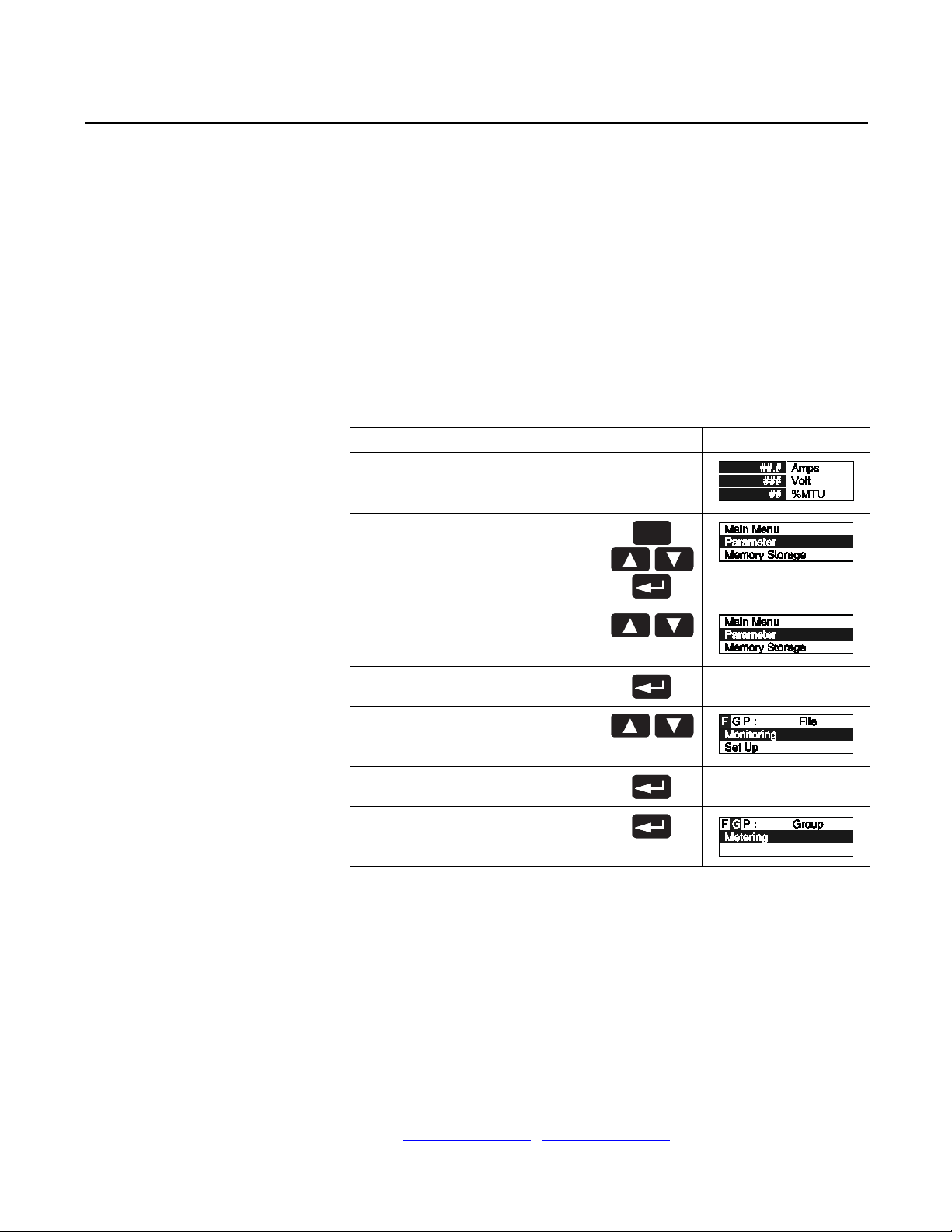
Metering
Sel
Esc
Chapter 5
Overview
Viewing Metering Data
While the SMC Flex controller operates your motor, it also monitors several
different parameters, providing a full function metering package.
To access the metering information, follow the procedure below:
Description Action Display
––
1. Press any key to access the Main menu.
2. Scroll with the Up/Down keys until the Parameter
option is shown.
3. Press the Enter key to access the Parameter option.
4. Scroll with the Up/Down keys until the Monitoring
option is displayed.
(1)
–
5. Press the Enter key to access the Monitoring group.
6. Press the Enter key to access the Metering group.
(1) Refer to Metering on page 16 of Chapter 1 or Figure 43 on page 73 of Chapter 4 for details on the metering functions.
Rockwell Automation Publication 1560E-UM051F-EN-P - June 2013 87
–
Page 98
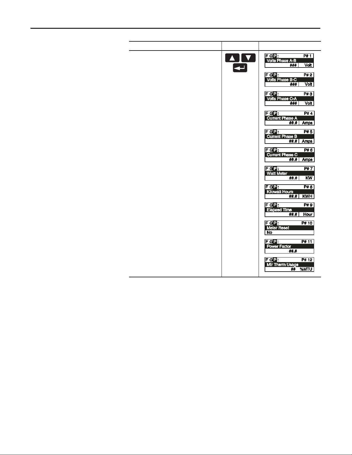
Chapter 5 Metering
Description Action Display
7. Scroll through the Metering parameters with the
Up/Down keys to access the desired information.
Press the Enter key to view that parameter.
The metering values that are displayed on the SMC Flex can be modified to show
you desired values by accessing Main Menu/Preferences.
88 Rockwell Automation Publication 1560E-UM051F-EN-P - June 2013
Page 99

Options
TIP
II
OO
Sel
Jog
II
OO
Sel
Jog
Chapter 6
Overview
Human Interface Module
The SMC Flex controller offers a variety of unique control programming and
communication options that provide enhanced capabilities (refer to Chapter 1
for brief descriptions of each option).
Only one option can reside in a controller.
The control buttons available with the Bulletin 20-HIM Human Interface
Modules are compatible with the SMC Flex controller’s control options. The
following table details the functionality of each button with regards to each
option.
Notes:
1. The logic mask port must be enabled prior to initiating control commands
to the SMC Flex controller. Refer to Control Enable
on page 106 of
Chapter 8 for instructions.
2. The control terminals must be wired according to Figure 36 on page 62
and Figure 37 on page 63
Option Action Operation
Standard
Soft Stop
Current Limit
Full Voltage
Linear Speed
.
The green start button, when pressed, will commence
motor acceleration to full speed.
The red stop button, when pressed, will provide a coast
stop, and/or reset a fault.
The jog button, when pressed, will initiate the
Preset Slow Speed
Rockwell Automation Publication 1560E-UM051F-EN-P - June 2013 89
programmed maneuver.
The green start button, when pressed, will commence
motor acceleration to full speed.
The red stop button, when pressed, will provide a coast
stop.
The jog button is not active for Preset Slow Speed.
* Slow Speed cannot be operated via the HIM.
Page 100

Chapter 6 Options
II
OO
Sel
Jog
II
OO
Sel
Jog
II
OO
Sel
Jog
II
OO
Sel
Jog
Option Action Operation
Pump Control
Pump Control
The green start button, when pressed, will commence
motor acceleration to full speed.
The red stop button, when pressed, will provide a coast
stop, and/or reset a fault.
The jog button, when pressed, will initiate a pump stop
maneuver.
The green start button, when pressed, will commence
motor acceleration to full speed.
Braking Control
(1)
Smart Motor Braking
The red stop button, when pressed, will provide a coast
stop, and/or reset a fault.
The jog button, when pressed, will initiate a brake stop.
Accu-Stop
The green start button, when pressed, will commence
motor acceleration to full speed.
The red stop button, when pressed, will provide a coast
stop, and/or reset a fault.
With a “stopped” status, the jog button, when pressed,
will initiate slow speed motor operation. From an “at
speed” condition, the jog button, when pressed, will
initiate braking to slow speed operation. The controller
will maintain slow speed operation as long as the jog
button is pressed.
Slow Speed with Braking
The green start button, when pressed, will commence
motor acceleration to full speed.
The red stop button, when pressed, will provide a coast
stop, and/or reset a fault.
The jog button will initiate a brake stop.
(1) Bra king Control is not offere d for standa rd use in MV a pplications. Please consult factory for further assistance.
* Slow Speed cannot be operated via the HIM.
ATT EN TI ON : The Bulletin 20-HIM interface module’s stop push button is not
intended to be used as an emergency stop. Refer to the applicable standards for
emergency stop requirements.
90 Rockwell Automation Publication 1560E-UM051F-EN-P - June 2013
 Loading...