

Page 1
Triguard SC300E
MRB04XM
Remote Bus Extender Master
INTRODCUTION
PURPOSE
Module
(MRB04XM)
Issue 5
October 2005
A Remote Bus Extender Master Module MRB04XM (Figure 1-1 ) is located in each of the three
-
hand slots of any local extension chassis that is connected via fibre op
right
remote extension chassis. The three Master Modules (A, B and C), together with their
corresponding Remote Slave Modules, provide an interface between the processor modules
(MPPs) in the main chassis, the I/O modules in the extension chassis and the I/O modules in
the remote chassis.
This document is intended to provide a general understanding of the function of the Remote
Bus Extender Master module sufficient to enable basic maintenance operations to be effected
in the field.
ASSOCIATED DOCUMENTATION
Reference No
008-5097
008-5100
008-5115
Chassis User Manual
MPP Processor Module User Manual
TBA Bus Expansion Adaptor User Manual
Title
tic links to a
008-5118
008-5217
MRB01XS Remote Bus Extender Slave Module User Manual
TBT Bus Terminator User Manual
008-5117
Page 2
2
MRB04XM
October
2005–
Issue 5
Triguard
SC300E
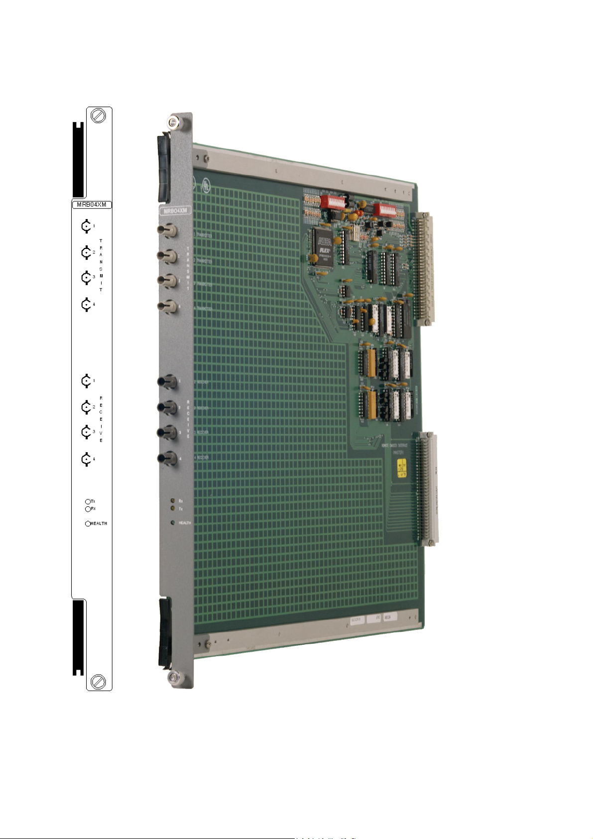
Figure 1-1 MRB04XM General view and front panel detail
Page 3

MRB04X
M
October
2005–
Issue 5
3
Triguard
SC300E MRB04XM Remote Bus Extender Master Module
SPECIFICATION
Model
MRB04XM
Fibre optic ports
Fibre optic cable (not supplied)
Maximum drive loss
Indicators
Module power consumption
Overall size (mm)
Overall size (inches)
Weight
ENVIRONMENTAL SPECIF
The maximum ambient
not be greater than 60 degrees centigrade.
shall
Temperature operating:
ICATIONS
temperature measured at the hottest point within the Triguard system
+5°C to +60°C
4 transmit, 4 receive
Multimode 62.5/1259m cable & 50/1259m
cable
(ST connector to ST connector)
50/1259m cable = 9dB
62.5/1259m cable = 16dB
Health, Tx, Rx
3W
400(9U)H x 397L x 28W
15.75H x 15.63L x 1.1W
1.0kg
Temperature
Humidity
Certi
fication:
General Certification: Ref. SC300E TMR Product Guide (ref 008-5209)
storage:
-
25°C to +70°C
5% to 95% non-condensing at ambient <40°C
TRANSPORT AND HANDLING
The MRB04XM must be transported and stored in its original packing material which should be
retained
for this purpose.
Page 4

4
MRB04XM
October
2005–
Issue 5
Triguard
SC300E
TECHNICAL DESCRIPTIO
N
PHYSICAL
Th
e MRB04XM Remote Bus Extender Master Module is a 9U high PCB with integral front
panel. A general view of the main components is shown in Figure 2-1 . DIP switches SW1 and
SW2 are used to set the enable and addresses of up to four remote chassis.
EXTERNAL CONNECTIONS
Each module is plugged into an extension chassis backplane bus system via two DIN41612
connectors J1 and J2 (Figure 2-1 ). The connections to remote chassis are serial links along
fibre-optic cables which plug into ST type transmitter and receiver connections on the front
panel. The top four connectors are the transmitters and the lower four are receivers enabling
two
-
way communication between the master modules and up to four slave modules in remote
chassis.
CHASSIS BACKPLANE
The signals passin
backplane. The rear backplane connectors are shown in Figure 2-6.For additional information,
refer
to
the Chassis user manual (Ref 008-5097).
g through J1 and J2 are available at the rear of the extension chassis
Connector J1 links the Remote Bus Extender to the I/O modules in the local chassis.
Extensions are provided to the pins of the J1 mating connector (96 pins in three columns ‘a’, ‘b’
and
‘c’). Pins 07 to 10 of columns ‘b’ and ‘c’ are specially extended to enable the installation of
the chassis ad
The I/O modules interface to three isolated communications buses (shown collectively as the
‘I/O Bus’ in Figure 2-5 ), each bus being served by one of the Remote Bus Extenders. Columns
‘a’ and ‘c’ of connectors J2 link each Remote Bus Extender to the expansion bus via rear
backplane connectors ‘e’. The same basic chassis is used for the main chassis, the extension
chassis and the remote chassis.
The following chassis backplane features are not used in the extension c
this
time:/
1.
2.
3.
Di
dress setting links (see Figure 2-6).
hassis application at
The inter-processor communications bus (Figure 2-5 ) and hence Column ‘b’ of
connector J2/backplane connector ‘e’
Watchdog timer ‘WDT’ connectors ‘f’ (Figure 2-6 )
agnostic serial ports ‘g’ (Figure 2-6
).
Page 5

MRB04X
M
October
2005–
Issue 5
5
Triguard
SC300E MRB04XM Remote Bus Extender Master Module
U18 (FPGA) Switch
S1 Fuse F1
Switch
S2
 Loading...