

Page 1
Triguard SC300E
MRB01XS
Remote Bus Extender Slave Module
(MRB01XS)
Issue 4
INTRODUCTION AND TEC
HNICAL DATA
PURPOSE
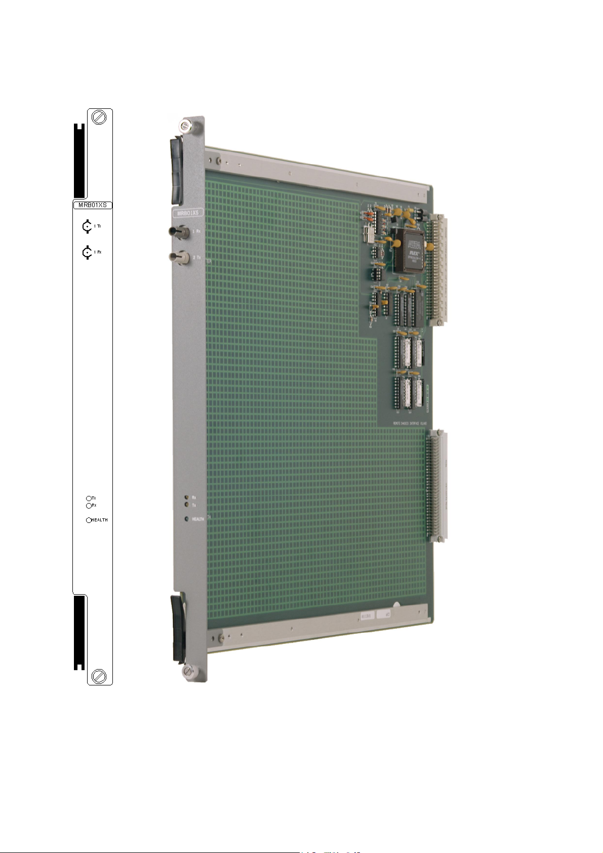
A Remote Bus Extender Slave Module MRB01XS (Figure 1-1 ) is located in each of the three
right-hand slots (A, B and C) of a remote extension chassis. Fibre optic cables link each
MRB01XS to a corresponding master module (MRB04XM) in a local extension chassis. The
master
and slave modules operate together as part of an interface between the I/O modules in
the
remote extension chassis and the processor m
odules (MPPs) in the main chassis.
October 2005
Figure 2-2 shows how the MRB01XSs are linked by fibre optic cables to the MRB04XMs and
then
by
ribbon cables to the MPPs.
This document is intended to provide a general understanding of the function of the MRB01XS
suff
icient to enable basic maintenance operations to be effected in the field.
The chassis that contains the MRB01XS will be referred to as the ‘remote’ chassis throughout
this
document.
ASSOCIATED DOCUMENTATION
Reference No
008-5097
008-5100
008-5117
Title
Chassis Use
MPP Processor Module User Manual
MRB04XM Remote Bus Extender Master Moudle User Manual
NOTE
r Manual
008-5217
TBT Bus Terminator User Manual
008-5118
Page 2
2
MRB01X
S
Octob
er
2005
–
Issue 4
Triguard SC300E
Figure 1-1 MRB01XS General view and front panel detail
Page 3
MRB01X
S
October
2005–
Issue 4
3
Triguard
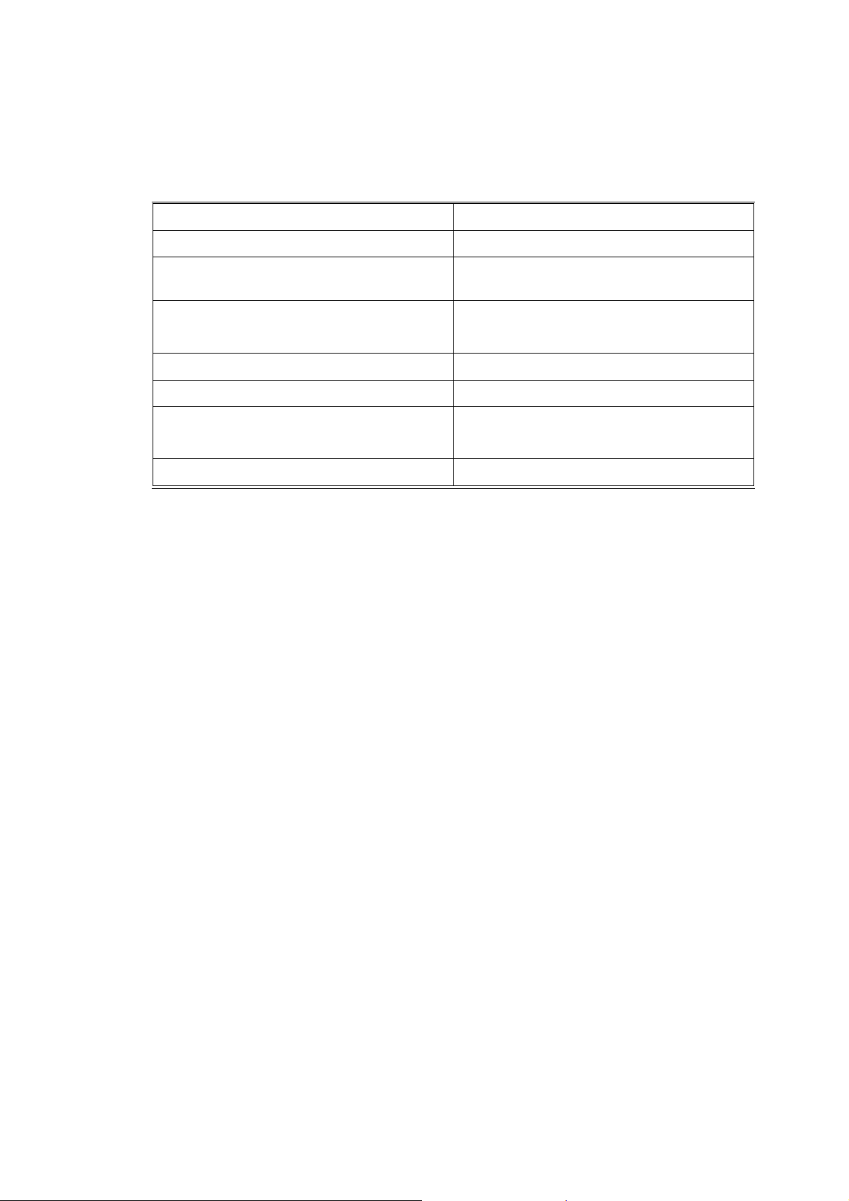
SPECIFICATION
Model
Fibre
optic ports
SC300E MRB01XS Remote Bus Extender Slave Module
MRB01XS
1 transmit, 1 receive
Fibre optic cable (not supplied)
Maximum drive loss
Indicators
Module power consumptin
Overall size (mm)
Overall size (inches)
Weight
ENVIRONMENTAL SPECIF
The maximum ambient temperature measured at the hottest point within the Triguard system
shall
not be greater than 60 degrees centigrade.
Temperature operating:
Temperature
storage:
Multimode 62.5/125;m cable & 50/125;m
cable (ST connector to ST connector)
50/125;m cable = 9dB
62.5/125;m cable = 16dB
Health, Tx, Rx
3W
400(9U)H x 397L x 28W
15.75H x 15.63L x 1.1W
1.0kg
ICATIONS
+5°C to +60°C
-
25°C to +70°C
Humidity:
Certification:
General Certification: Ref. SC300E TMR Product Guide (ref 008-5209)
5% to 95% non-condensing at ambient <40°C
TRANSPORT AND HANDLING
The MRB01XS must be transported and stored in its original packing material which should be
retained
for this purpose.
Page 4
4
MRB01X
S
Octob
er
2005
–
Issue 4
Triguard SC300E
TECHNICAL DESCRIPTIO
N
PHYSICAL
The MRB01XS Remote Bus Extender Slave Module is a 9U high PCB with integral front panel.
A general vie
EXTERNAL CONNECTIONS
The MRB01XS is plugged into the remote chassis backplane bus system via two DIN41612
connectors J1 and J2.
Connections to the associated master module are via fibre-optic cables which plug into
transmitter and receiver connections on the front panel.
w of the main components is shown in Figure 2-1
.
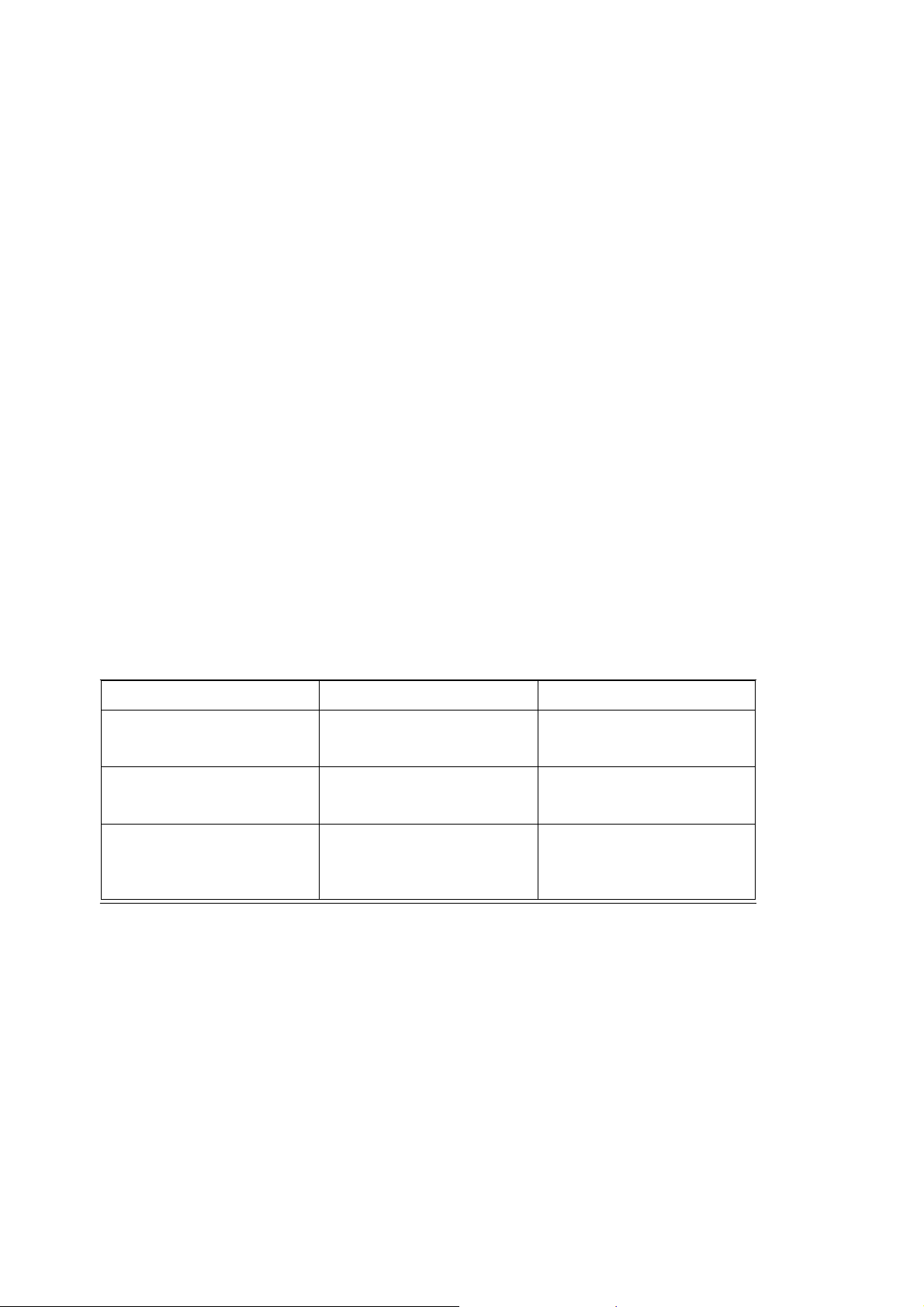
CONNECTOR SUMMARY
Type
96-pin DIN41612 type C male
96-pin DIN41612 type C male
ST
Connected by 62.5/125 m
multimode
cable
Connector
J1 (I/O bus)
J2 (expansion bus)
Transmit (Tx) and
Receive (Rx)
Table 2-1. Connector summary
Rear edge of MRB01XS
(Figure 2
Rear edge of MRB0
(Figure 2
MRB01XS front panel
Location
-
1 )
-
1 )
1XS
CONFIGURATION AND INDICATORS
The MRB01XS has no user configuration.
The Tx and Rx LEDS on the front panel flash to indicate that their respective fibre optic links
are
passing data.
The single Health indicator (green LED) on the frontpanel illuminates in normal operation
.
Page 5

MRB01X
S
October
2005–
Issue 4
5
Triguard
SC300E MRB01XS Remote Bus Extender Slave Module
U3 (FPGA)
Fuse F1
Connector J1
Connector J2
Figure 2-1 MRB01XS Side view
Page 6

6
MRB01X
S
Octob
er
2005
–
Issue 4
Triguard SC300E
EXPANSION BUS
Expansion bus architecture
The main and any local extension chassis are interconnected by ribbon cables running
between
Figure
master
fibre-optic cables terminated at master and slave remote bus extender modules.
The maximum number of remote chassis per SC300E system is eleven—given by the
combination: 1 x main + 3 x local + 11 x remote = 15 chassis total.
expansion bus connectors ‘e’ on their respective chassis backplanes as shown in
2-2.
The expansion bus may be further extended to up to four remote chassis per
module (up to an overall maximum of 15 chassis per SC300E system) by means of
Figure 2-2 Bus extension to remote chassis
NOTE
The Remote Bus Extender Slave Modules will only support the chassis in which they are fitted.
Additional
chassis CANNOT be added to a Remote Extension Chassis.
THEORY OF OPERATION
Figure 2-2 shows the general architecture of the system and identifies the position of the
MRB01XS.
chassis
one
end of the fibre optic data link, operating as a slave to the associated maste
the other end of the link.
The overall function of the system is to interface the I/O modules of the remote
with the processors in the main chassis. At a local level, the MRB01XS terminates
r module at
Page 7

MRB01X
S
October
2005–
Issue 4
7
Triguard
SC300E MRB01XS Remote Bus Extender Slave Module
Remote chassis address selection is controlled from the associated remote bus extender
master module MRB04XM. Refer to the Remote Bus Extender Master Module User Manual
(Ref 008-5117) for details. There are no address setting links or switches on the MRB01XS
itself. The chassis address setting links ‘UNIT ID 0 to 3’ at the rear of the remote chassis
backplane are not used. Links fitted in these positions will have no effect.
The primary function of the MRB01XS is to respond to remote chassis I/O module read/write
requests received via the fibre optic data link.
The presence of the fibre optic data link precludes the use of a serial communications module
in a remote chassis. All other types of I/O module are supported.
The module provides identical timing for remote chassis I/O operations as the MPP provides for
main
chassis I/O operations.
Although the MRB01XS is part of a triplicated system, the module itself is simplex in
operation. Redundancy derives from the fact that there are three such modules in each remote
chassis.
The MRB01XS supports both single and dual slot hot repair.
Figure 2-4 shows the main functional areas of the MRB01XS circuit. Buffers regulate the two
way flow of data and control signals t
logic.
hrough the module, under the overall control of the control
Power supplies
A pair of auctioneering diodes combines the two 5.4Vdc power supplies from the chassis
mounted PSUs into a single 5Vdc (nominal) supply for the module. Capacitive decoupling and
overcurrent
protection is provided.
-
-
Page 8

8
MRB01X
S
Octob
er
2005
–
Issue 4
Triguard SC300E
UNIT
ID
UNIT
ID
0
1
2
3
0
1
2
3
UNIT
ID
0
1
2
3
Figure 2-3 MRB01XS -
Related backplane connectors
Page 9

MRB01X
S
October
2005–
Issue 4
9
Triguard
SC300E MRB01XS Remote Bus Extender Slave Module
Figure 2-4 MRB01XS -
Block diagram
Page 10

10
MRB01X
S
Octob
er
2005
–
Issue 4
Triguard SC300E
SERVICING
SCOPE
The MRB01XS is not field repairable. Field servicing operations are confined to the total
replacement of faulty MRB01XS.
Return the faulty MRB01XS for repair.
DIAGNOSIS
A faulty MRB01XS will be apparent by a single I/O channel failure affecting all the field devices
serviced
by
a particular remote chassis. The Health LED may also be extinguis
hed
CONFIGURATION
There are no configurable links or switches.
REMOVAL AND REPLACEMENT
There are no special warm start or other removal and replacement procedures. Simply withdraw
the
faulty module, replace it with a good one, and check that the Health LED
illuminates.
Page 11

MRB01X
S
October
2005–
Issue 4
11
Triguard
SC300E MRB01XS Remote Bus Extender Slave Module
SERVICE SUPPORT
SPARE PARTS
Spare parts and technical advice can be obtained from your local area offices
.
 Loading...