

Page 1

DC3E Non-Regenerative DC Drive
User Guide
1/4 to 2 HP, 115/230 VAC
Instruction Manual D2-3452-1
M/N DC3N-12D-00-010-AI
M/N DC3N-12D-4X-010-AI
250-0287-rev2.qxd 3/12/01 10:27 AM Page a
Page 2

The information in this manual is subject to change without
notice.
Throughout this manual, the following notes are used to alert
you to safety considerations:
ATTENTION: Identifies information about practices or
circumstances that can lead to personal injury or death,
property damage, or economic loss.
IMPORTANT: Identifies information that is critical for successful
application and understanding of the product.
250-0287-rev2.qxd 3/12/01 10:27 AM Page b
Trademarks not belonging to Rockwell Automation are property
of their respective companies.
©2001 Rockwell International Corporation All rights reserved
Page 3

i
ATTENTION: Only qualified personnel familiar with the
construction and operation of this equipment and the
hazards involved should install, adjust, operate, and/or
service this equipment. Read and understand this
instruction manual in its entirety before proceeding.
Failure to observe this precaution could result in severe
bodily injury or loss of life.
ATTENTION: The user is responsible for conforming
with all applicable local and national codes. Failure to
observe this precaution could result in severe bodily
injury or loss of life.
ATTENTION: The control circuit is at line potential
when the drive is energized. Use a non-metallic
screwdriver when making adjustments to the circuit
board potentiometers. Exercise extreme caution as
hazardous voltage exists. Failure to observe these
precautions could result in severe bodily injury or loss of
life.
ATTENTION: It is possible for a drive to run at full
speed as a result of a component failure. Please
ensure that a master switch has been placed in the AC
line to stop the drive in an emergency.
ATTENTION: Reduce the chance of an electrical fire,
shock, or explosion by proper grounding, over-current
protection, thermal protection and enclosure. Follow
sound maintenance procedures.
250-0287-rev2.qxd 3/12/01 10:27 AM Page i
Page 4

ii Safety Warnings
ATTENTION: Starting and stopping with the start/stop
terminals does not disconnect AC power in the stop
position. A hardwired AC power disconnection switch
must be mounted between the AC source and terminals
L I and L2. This is required, as the DC drive does not
have an armature loop contactor. A single fault like a
power device short may cause motor rotation when in
the stop mode. The user is responsible for assuring safe
conditions for operating personnel by providing suitable
guards, audio or visual alarms, or other devices. Failure
to observe these precautions could result in bodily injury.
ATTENTION: This Drive contains ESD (Electric Static
Discharge) sensitive parts and assemblies, Static control
precautions are required when installing, testing,
servicing, or repairing this assembly. Failure to observe
these precautions could result in damage to, or
destruction of, the equipment.
250-0287-rev2.qxd 3/12/01 10:27 AM Page ii
Page 5

Specifications 1
Dimensions and Layout 4
Installation 7
Wiring ...............................................8
Shielding guidelines ..................................8
Chassis drive ........................................10
Mounting ..........................................10
Isolation transformer ..................................11
Heat sinking .......................................12
Fusing ............................................12
Line fusing . . ....................................13
Speed adjust potentiometer ............................14
Alternate speed adjust potentiometer connections .........15
Cage-clamp terminals ...............................16
Connections ........................................17
Motor ...........................................18
Power input . . ....................................19
Field output . . ....................................20
START/STOP pushbuttons ...........................21
Tachometer feedback ...............................22
Voltage or current follower ...........................24
Enclosed drive .......................................25
Mounting ..........................................25
Heat sinking .......................................26
Line fusing .........................................26
Connections ........................................27
Motor ...........................................28
Power input . . ....................................29
Contents
iii
250-0287-rev2.qxd 3/12/01 10:27 AM Page iii
Page 6

Field output . . ....................................29
Tachometer feedback ...............................30
Voltage or current follower ...........................32
Slide switches ........................................33
LINE VOLTAGE (SW501 and SW502) ....................33
MOTOR (SW503) ...................................33
SIGNAL (SW504) ...................................34
FEEDBACK (SW505) .................................34
Operation 36
Before applying power (all models) .........................37
Drive operation .......................................38
Chassis drive operation ...............................38
POWER ON start .................................38
Pushbutton start/stop ...............................39
Alternate Starting and Stopping Methods ..................41
Minimum speed ...................................42
Dynamic braking ..................................43
Dynamic brake resistor value ........................43
Enclosed drive operating modes .........................45
Manual mode ....................................45
Auto mode . . ....................................46
Enclosed drive operation ..............................46
To run the motor ...................................47
To stop the motor .................................47
Calibration 48
Drive Calibration Procedure .............................50
MINSPD ..........................................51
MAXSPD .........................................52
CURRENT LIMIT ....................................53
IRCOMP .........................................54
Approximate IR COMP calibration: ....................55
ACCEL ...........................................55
iv Table of Contents
250-0287-rev2.qxd 3/12/01 10:27 AM Page iv
Page 7

DECEL ...........................................56
TACHVOLTS.......................................57
Application Notes 60
Multiple fixed speeds ...................................60
Adjustable speeds using potentiometers in series .............61
Independent adjustable speeds ...........................62
Reversing ...........................................63
RUN/JOG switch . . ....................................65
Before troubleshooting .................................67
Troubleshooting 67
Diagnostic LEDs . . ....................................68
Block Diagram ........................................75
Terminal descriptions ..................................76
Chassis drive terminals ...............................76
Enclosed drive terminals ..............................77
CE Compliance 78
Exhibit “A” ...........................................79
Armature Filters . . ....................................80
Notes 82
vTable of Contents
250-0287-rev2.qxd 3/12/01 10:27 AM Page v
Page 8

Figure 1. DC3N-12D-00-010-AI Dimensions ..................4
Figure 2. DC3N-12D-4X-010-AI Dimensions ..................5
Figure 3. PC Board Layout ...............................6
Figure 4. Speed Adjust Potentiometer ......................14
Figure 5. Cage-Clamp Terminal ...........................16
Figure 6. Chassis Drive Connections .......................23
Figure 7. Chassis Drive Signal Follower Connection ...........24
Figure 8. Enclosed Drive Connections ......................31
Figure 9. Slide Switches ................................35
Figure 10. Run/Decelerate to Minimum Speed Switch ...........42
Figure 11. Dynamic Brake Connection .......................44
Figure 12. Calibration Trimpot Layout .......................49
Figure 13. Typical CURRENT LIMIT and IR COMP Settings ......59
Figure 14. Multiple Fixed Speeds ..........................60
Figure 15. Adjustable Fixed Speeds Using Potentiometers in Series 61
Figure 16. Independent Adjustable Speeds ...................62
Figure 17. Reversing Circuit Connection .....................64
Figure 18. RUN/JOG Switch Connection to Speed Adjust
Potentiometer ...............................66
Figure 19. Diagnostic LED Locations ........................68
Figure 20. DC3N Block Diagram ...........................75
vi
Illustrations
250-0287-rev2.qxd 3/12/01 10:27 AM Page vi
Page 9

Specifications
Max.
Armature HP Range HP Range
Current with115 VAC with 230 VAC
Model (Amps DC) Applied Applied
DC3N-12D-00-010-AI 10A 1/4–1 1/2–2
DC3N-12D-4X-010-AI 10A 1/4–1 1/2–2
Model Style
DC3N-12D-00-010-AI Open chassis
DC3N-12D-4X-010-AI NEMA 4X/12
AC Line Voltage 115 VAC or 230 V AC, 50 or 60 Hz, 1 Phase
Maximum Allowable Symmetrical AC Line Current 5000 amps
Maximum AC Line Distribution kVA
with 115 VAC Input 25 kVA
with 230 VAC Input 50 kVA
Armature Voltage
With 115 VAC Input 0–90 VDC
With 230 VAC Input 0 – 180 VDC
Field Voltage
115 VAC Input 50 VDC (F1 to L1); 100 VDC (F1 to F2)
230 VAC Input 100 VDC (F1 to L1); 200 VDC (F1 to F2)
Maximum Field Current 1 ADC
Adjustments and Application Data
Form Factor 1.37 at base speed
Service Factor 1
Maximum Speed Trimpot Range (% of rated voltage) 0to90%
1
250-0287-rev2.qxd 3/12/01 10:27 AM Page 1
Page 10

Minimum Speed Trimpot Range (% of rated voltage) 0to50%
Torque Trimpot Maximum Setting (% of maximum current) 200%
IR Drop Compensation (% of rated armature voltage) 0to15%
Acceleration Time Range 0.5 – 10 seconds
Deceleration Time Range 0.5 – 10 seconds
Analog Input Signal Range (S1 to S2) 0 – 10 VDC or 4 – 20 mADC
Input Impedance (S1 to S2) >100 KOHMS
Speed Regulation (% of base speed with 95% load change)
With Armature Feedback 1% or better
With Tachometer Feedback 0.1%
Speed Range 60:1
Tachometer Feedback Voltage Range
7 – 50 VDC per 1000 RPM
Maximum Current Load 150% for 1 minute
Safety Certification UL Listed Component
cUL Listed Component
CE Approved Component
Weight 2.1 lbs (953g)
Service Conditions
Maximum Allowable Elevation
3300 ft (1000 m) max without derating*
Vibration 0.5G max. (0–50 Hz); 0.1G max. (>50 Hz)
Ambient Temperature Range
Chassis Drives 10°C – 55°C
Enclosed Drives 10ºC – 45ºC
Non-condensing Relative Humidity 0% to 95%
* Derate the current by 1% for every 300 ft (90m) above 3300 ft., up to 10,000 ft.
(3000m)
2 Specifications
250-0287-rev2.qxd 3/12/01 10:27 AM Page 2
Page 11

Drive Ratings
DC Motor Motor
Rated DC Armature Field Field
Motor AC Line Input Armature Current Voltage Current
HP Amps KVA Voltage (Amps) (Amps)
1/4 4.5 0.5 90 2.7 50 1
4.5 0.5 90 2.7 100 1
1/3 5.9 0.7 90 3.5 50 1
5.9 0.7 90 3.5 100 1
1/2 7.8 0.9 90 5 50 1
3.7 0.8 180 2.5 100 1
3.7 0.8 180 2.5 200 1
3/4 10.6 1.2 90 7.6 50 1
5.6 1.3 180 3.8 100 1
5.6 1.3 180 3.8 200 1
1 13 1.5 90 10 50 1
7 1.6 180 5 100 1
7 1.6 180 5 200 1
1.5 -- -- -- -- -- --
10.1 2.3 180 7 100 1
10.1 2.3 180 7 200 1
2------ ------
12 2.8 180 9.2 100 1
12 2.8 180 9.2 200 1
Efficiency (at maximum horsepower output) 92%
3Specifications
250-0287-rev2.qxd 3/12/01 10:27 AM Page 3
Page 12
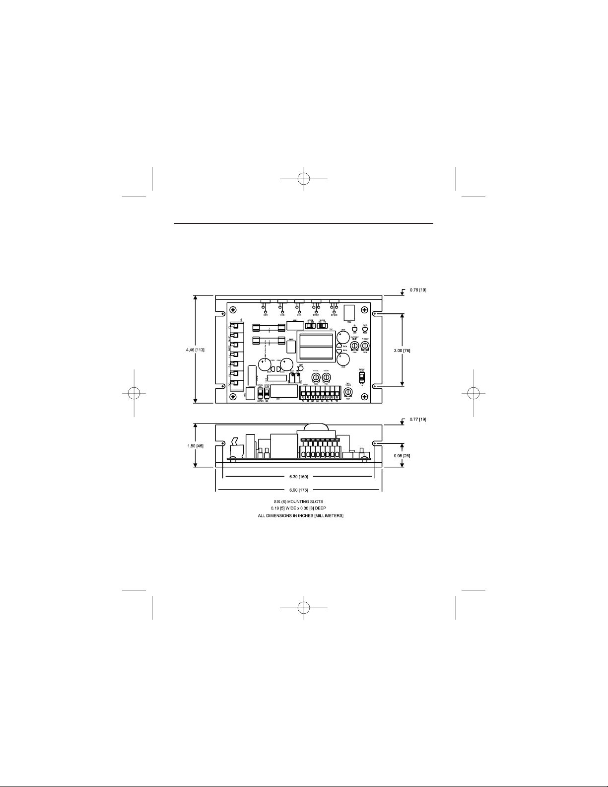
4
Dimensions and Layout
Figure 1. DC3N-12D-00-010-AI Dimensions
250-0287-rev2.qxd 3/12/01 10:27 AM Page 4
Page 13
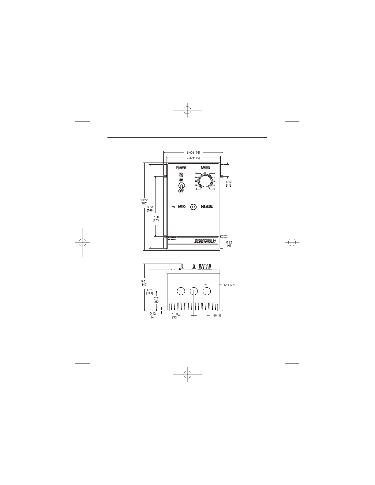
5Dimensions
THREE 0.88 [22] KNOCKOUTS
ALL DIMENSIONS IN INCHES [MILLIMETERS]
Figure 2. DC3N-12D-4X-010-AI Dimensions
250-0287-rev2.qxd 3/12/01 10:27 AM Page 5
Page 14
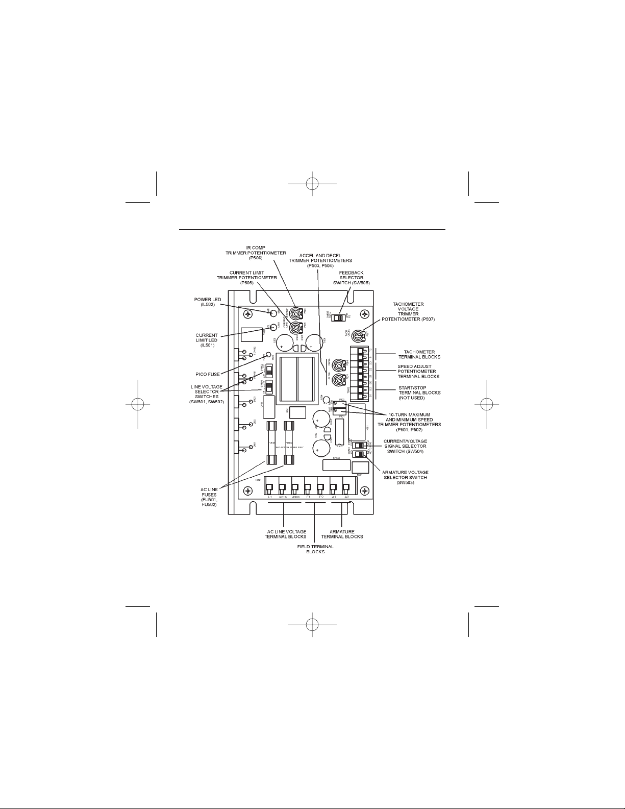
6 Dimensions and Layout
Figure 3. PC Board Layout
250-0287-rev2.qxd 3/12/01 10:27 AM Page 6
Page 15

7
Installation
ATTENTION: Only qualified technical personnel,
familiar with the construction and operation of this
equipment and the hazards involved, should install,
adjust, operate and/or service this equipment. Read and
understand this instruction manual in its entirety before
proceeding. Failure to observe this precaution could
result in severe bodily injury or loss of life.
ATTENTION: This equipment is at line voltage when
AC power is connected. Disconnect and lockout all
ungrounded conductors of the AC power line before
working on the unit. Failure to observe this precaution
could result in severe bodily injury or loss of life.
ATTENTION: The user is responsible for conforming
with all applicable local and national codes. Failure to
observe this precaution could result in severe bodily
injury or loss of life.
250-0287-rev2.qxd 3/12/01 10:27 AM Page 7
Page 16

Wiring
8 Installation
ATTENTION: Circuit potentials are at 115 or 230
VAC above ground. To prevent the risk of injury or
fatality, avoid direct contact with the printed circuit
board or with circuit elements. Use a non-metallic
screwdriver for the calibration trimpots.
ATTENTION: Do not disconnect any of the motor
leads from the drive unless power is removed or the
drive is disabled. Opening any one motor lead may
destroy the drive.
Use 18-24 AWG wire for speed adjust potentiometer
wiring. Use 14–16 AWG wire for AC line (L1, L2) and
motor (A1 and A2) wiring.
Shielding guidelines
ATTENTION: If it is not practical to shield power
conductors, Reliance Electric recommends shielding all
logic-level leads. If shielding logic leads is not
practical, use twisted-pair control wiring to minimize
induced electrical noise.
250-0287-rev2.qxd 3/12/01 10:27 AM Page 8
Page 17

9Installation
*Reliance Electric considers this an unfavorable condition and does not
recommend bundling power and logic leads for any length.
ATTENTION: Under no circumstances should power
and logic leads be bundled together. Induced voltage
can cause unpredictable behavior any electronic device,
including motor controls.
As a general rule, Reliance Electric recommends shielding
of all conductors if:
1) wire lengths exceed 4 inches and power and logic leads
must be bundled together*; or
2) radiated and/or conducted noise must be minimized due
to concerns about immunity or general compliance (CE,
FCC, etc.)
It may be necessary to earth ground the shielded cable. If
noise is produced by devices other than the drive, ground
the shield at the drive end. If noise is generated by a
device on the drive, ground the shield at the end away from
the drive. Do not ground both ends of the shield.
If the device continues to pick up noise after grounding the
shield, it may be necessary to add AC line filtering devices,
or to mount the drive in a less noisy environment.
250-0287-rev2.qxd 3/12/01 10:27 AM Page 9
Page 18

10 Installation
Mounting
Protect the drive from dirt, moisture, and accidental
contact. Provide sufficient room for access to the terminal
block and calibration trimpots.
Mount the drive away from other heat sources. Operate the
drive within the specified ambient operating temperature
range.
Prevent loose connections by avoiding excessive vibration
of the drive.
Mount the drive with its board in either a horizontal or
vertical plane. Four 0.19 inch (5 mm) wide slots in the
chassis accept #8 pan head screws.
ATTENTION: This drive contains ESD (Electric Static
Discharge) sensitive parts and assemblies. Static control
precautions are required when installing, testing,
servicing, or repairing this assembly. Failure to observe
these precautions could result in damage to, or
destruction of, the equipment.
Chassis drive
250-0287-rev2.qxd 3/12/01 10:27 AM Page 10
Page 19

The chassis units do not have to be earth grounded. If you
choose to ground the chassis, use a star washer beneath the
head of at least one of the mounting screws to penetrate the
anodized chassis surface and to reach bare metal.
Isolation transformer
11Installation
ATTENTION: Distribution system capacity above the
maximum recommended system KVA requires the use
of an isolation transformer, a line reactor, or other
means of adding similar impedance to the drive power
input. Failure to observe these precautions could result
in damage to, or destruction of, the equipment
Input isolation transformers might be needed to help
eliminate the following:
· Damaging line voltage transients from reaching the
drive.
· Line noise from the drive back to the incoming power
source.
· Damaging currents that could develop if a point inside
the drive becomes grounded.
250-0287-rev2.qxd 3/12/01 10:27 AM Page 11
Page 20

12 Installation
ATTENTION: Most code requires that upstream
branch protection be provided to protect input power
wiring. Failure to observe this precaution could result in
severe bodily injury or loss of life.
Observe the following guidelines when installing an
isolation transformer:
· A power disconnecting device must be installed between
the power line and primary of the transformer.
· If the power disconnecting device is a circuit breaker, the
circuit breaker trip rating must be coordinated with the
in-rush current (10-12 times full load current) of the
transformer.
Heat sinking
This DC3 drive model contains sufficient heat sinking in
its original configuration. No additional heat sinking is
necessary when installed in accordance with the guidelines
specified in this instruction manual. The chassis plate acts
as the thermal heatsink.
Fusing
Install the required, user-supplied branch circuit protection
fuses according to the applicable local, national, and
international codes (e.g., NEC/CEQ).
250-0287-rev2.qxd 3/12/01 10:27 AM Page 12
Page 21

13Installation
Line fusing
This DC3 drive model has 15-amp line fuses preinstalled
on fuse holders 501 and 502 (FU501 and FU502). When
replacing the line fuses, use fast acting fuses rated for 250
VAC or higher. See Figure 3, page 6, for fuse holder
location, and Table 1 for recommended replacement line
fuse sizes for specific application ratings.
Table 1. Recommended Line Fuse Sizes
90 VDC Motor 180 VDC Motor Max. DC Armature AC Line Fuse
Horsepower Horsepower Current (amps) Size (amps)
1/20 1/10 0.5 3
1/15 1/8 0.8 3
1/8 1/4 1.5 5
1/6 1/3 1.7 5
1/4 1/2 2.6 8
1/3 3/4 3.5 8
1/2 1 5.0 10
3/4 1 1/2 7.6 15
1 2 10 15
Reliance Electric offers a 0.5A pico fuse (part number 050–0074) which protects the control board power supply
transformer and logic.
250-0287-rev2.qxd 3/12/01 10:27 AM Page 13
Page 22
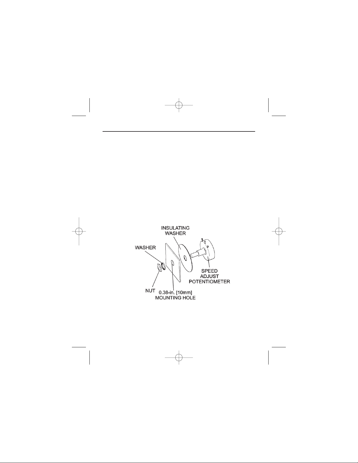
14
Figure 4. Speed Adjust Potentiometer
Installation
Speed adjust potentiometer
Install the circular insulating disk between the mounting
panel and the 10K ohm speed adjust potentiometer (see
Figure 4). Mount the speed adjust potentiometer through a
0.38 inch (10 mm) hole with the hardware provided. Twist
the speed adjust potentiometer wire to avoid picking up
unwanted electrical noise. If potentiometer leads are longer
than 18 inches (46 cm), use shielded cable.
250-0287-rev2.qxd 3/12/01 10:27 AM Page 14
Page 23

15
Alternate speed adjust potentiometer connections
Alternate speed adjust potentiometer connections may be
found in the Application Notes section of this user guide.
IMPORTANT: The user may choose to install a 5K ohm
speed adjust potentiometer; however, the MIN SPD and
MAX SPD trimpots must be recalibrated if the 5K ohm
potentiometer is used.
Installation
250-0287-rev2.qxd 3/12/01 10:27 AM Page 15
Page 24
16
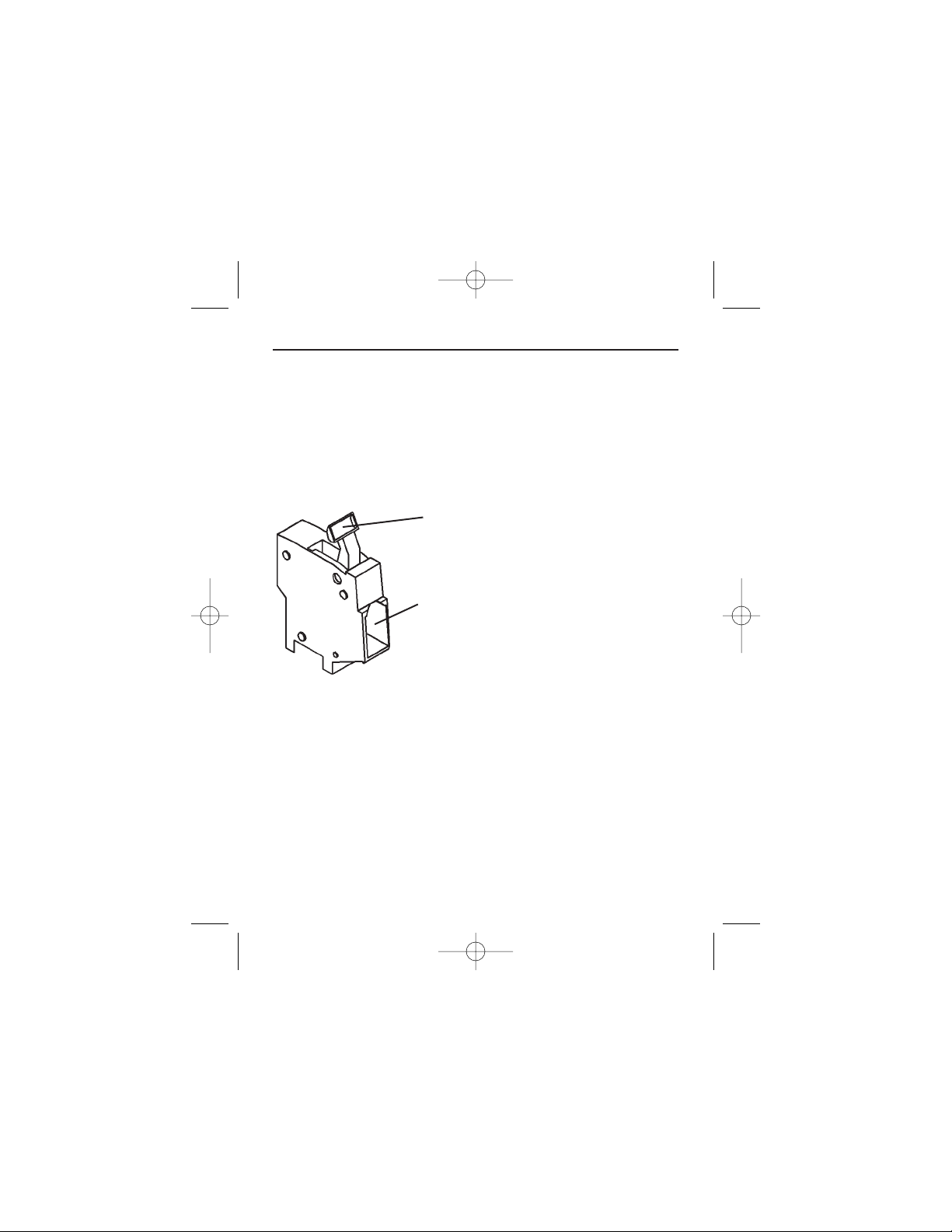
Cage-clamp terminals
Logic connections are made to cage-clamp terminals. To
insert a wire into the cage-clamp terminal:
Figure 5. Cage-Clamp Terminal
Installation
1. Press down on the lever arm using a
small screwdriver.
2. Insert wire into the wire clamp.
3. Release the lever arm to clamp wire.
250-0287-rev2.qxd 3/12/01 10:27 AM Page 16
Page 25

17Installation
ATTENTION: Do not connect this equipment with
power applied. Failure to follow this directive may
result in fire or serious injury.
ATTENTION: Starting and stopping with the start/stop
terminals does not disconnect AC power in the stop
position. A hardwired AC power disconnection switch
must be mounted between the AC source and terminals
L I and L2. This is required, as the DC3 drive does not
have an armature loop contactor. A single fault like a
power device short may cause motor rotation when in
the stop mode. The user is responsible for assuring safe
conditions for operating personnel by providing suitable
guards, audio or visual alarms, or other devices. Failure
to observe these precautions could result in bodily
injury.
ATTENTION: To provide the motor with overload
protection, local, national, and international codes
(e.g.,NEC/CEC) require that a motor thermostat,
internal to the motor, be installed or an electronic
thermal motor overload relay, sized to protect the
motor, be installed between the motor and the drives
output terminals.
Connections
250-0287-rev2.qxd 3/12/01 10:27 AM Page 17
Page 26

18 Installation
ATTENTION: Installation of a master power switch in
the input line is required. This is the only way to
disconnect power from the motor. The user is
responsible for assuring safe conditions for operating
personnel by providing suitable guards, audio or visual
alarms, or other devices. Failure to observe these
precautions could result in bodily injury.
Motor
ATTENTION: To provide the motor with overload
protection, local, national, and international codes (e.g.,
NEC/CEC) require that a motor thermostat, internal to
the motor, be installed or an electronic thermal motor
overload relay, sized to protect the motor, be installed
between the motor and the drive’s output terminals.
IMPORTANT: Reliance Electric drives supply motor
voltage from A1and A2 terminals. It is assumed throughout
this manual that, when A1 is positive with respect to A2,
the motor will rotate clockwise (CW) while looking at the
output shaft protruding from the front of the motor. If this
is opposite of the desired rotation, simply reverse the
wiring of A1 and A2 with each other.
250-0287-rev2.qxd 3/12/01 10:27 AM Page 18
Page 27

19Installation
Connect a motor to terminals A1 and A2 as shown in
Figure 6 (page 23). Ensure that the motor voltage rating is
consistent with the drive’s output voltage.
Power input
ATTENTION: Installation of a master power switch in
the input line is required. This is the only way to
disconnect power from the motor. The user is
responsible for assuring safe conditions for operating
personnel by providing suitable guards, audio or visual
alarms, or other devices. Failure to observe these
precautions could result in bodily injury.
Connect the AC line power leads to terminals L1 and L2 as
shown in Figure 6 (page 23). Install a master power switch
in the voltage input line, as shown in Figure 6. The switch
contacts should be rated at a minimum of 250 volts and
200% of maximum drive current.
250-0287-rev2.qxd 3/12/01 10:27 AM Page 19
Page 28

20 Installation
ATTENTION: Do not make any connections to F1 and
F2 when using a permanent magnet motor. The field
output is for shunt wound motors only. See Table 2 for
field output connections.
Table 2. Field Output Connections
Line Voltage Approximate Connect Motor
(VAC) Field Voltage (VDC) Field To
115 50 F1 and L1
115 100 F1 and F2
230 100 F1 and L1
230 200 F1 and F2
Field output
250-0287-rev2.qxd 3/12/01 10:27 AM Page 20
Page 29

21
START/STOP pushbuttons
Installation
Pushbutton operation of the DC3N drive requires that a
(momentarily) normally-closed STOP pushbutton be wired
to terminals B2 and B3 and a (momentarily) normally-open
START pushbutton wired to terminals B1 and B2. These
pushbuttons must be used together and are not included
with the drive. The B1, B2 and B3 terminals are on
terminal block 502 (TB502).
IMPORTANT: If the START/STOP pushbuttons are not
used, wire a jumper between terminals B1 and B3 to
bypass the latching circuit. The drive will then operate in a
power-up start mode. See Figure 6 (page 23) for these
switch connections.
ATTENTION: Starting and stopping with the start/stop
terminals does not disconnect AC power in the stop
position. A hardwired AC power disconnection switch
must be mounted between the AC source and terminals
L I and L2. This is required, as the DC3 drive does not
have an armature loop contactor. A single fault like a
power device short may cause motor rotation when in
the stop mode. The user is responsible for assuring safe
conditions for operating personnel by providing suitable
guards, audio or visual alarms, or other devices. Failure
to observe these precautions could result in bodily
injury.
250-0287-rev2.qxd 3/12/01 10:27 AM Page 21
Page 30

22 Installation
Using tachometer feedback improves speed regulation from
approximately 1% of motor base speed to approximately
0.1% of motor base speed. Use tachometers rated from 7
VDC per 1000 RPM to 50 VDC per 1000 RPM. Connect
the tachometer to terminals T1 and T2 of terminal block
502 (TB502). Place switch SW505 in the TACH position.
See Figure 6 for tachometer connections.
IMPORTANT: The TACH trimpot must be adjusted prior
to operating with tachometer feedback. Refer to the
Calibration section (pg 48) for instructions on calibrating
the TACH trimpot.
ATTENTION: Applying the incorrect polarity to the
tachometer can cause an overspeed condition. Make
sure the positive (+) wire is connected to terminal T1
and the negative (-) wire is connect to terminal T2 when
the motor is running in the forward direction. Failure to
observe this precaution could result in bodily injury.
Tachometer feedback
250-0287-rev2.qxd 3/12/01 10:27 AM Page 22
Page 31

Figure 6. Chassis Drive Connections
23Installation
NOTES
1. L1 IS THE HOT TERMINAL.
2. L2/115 IS THE NEUTRAL TERMINAL FOR 115 VAC INPUT.
3. L2/230 IS THE NEUTRAL TERMINAL FOR 230 VAC INPUT.
4. TYPICAL FIELD CONNECTIONS SHOWN. REFER TO TABLE 2 (PAGE 29)
FOR ALTERNATE FIELD CONNECTIONS.
250-0287-rev2.qxd 3/12/01 10:27 AM Page 23
Page 32

24 Installation
Figure 7. Chassis Drive Signal Follower Connection
Voltage or current follower
Instead of using a speed adjust potentiometer, these DC3N
model drives may be wired to follow an external input
signal (see Figure 7 for connections). This input signal can
be in the form of voltage (0-10 VDC) or current (4-20
mA). Because these drives have built in isolation the input
signal can be either grounded or ungrounded. The signal
slide switch must be set for current or voltage input,
depending on the input signal type (see Slide switches
section on pg 33).
COM (-)
250-0287-rev2.qxd 3/12/01 10:27 AM Page 24
Page 33

25
Enclosed drive
Mounting
The NEMA 4X enclosed drive comes with 0.88 inch (22
mm) conduit knockout holes at the bottom of the
enclosure. The units may be vertically wall mounted using
the four 0.19 inch (5 mm) slotted holes on the attached heat
sink. For motor loads less than 5 ADC, the drive may be
bench mounted horizontally, or operated without mounting.
Mount the drive as follows:
1. Install the mounting screws.
2. For access to the terminal strip, turn the slotted screw on
the front cover counterclockwise until it is free from the
enclosure. The right side of the cover is hinged to the
enclosure. Pull the slotted screw to open the enclosure.
3. Carefully remove the conduit knockouts by tapping them
into the enclosure and twisting them off with pliers.
4. Install conduit hardware through the 0.88 inch (22 mm)
knockout holes. Connect external wiring to the terminal
block.
5. Grasp the slotted screw and tilt the front cover back into
place. Avoid pinching any wires between the front cover
and the enclosure.
Installation
250-0287-rev2.qxd 3/12/01 10:27 AM Page 25
Page 34

26
6. Turn the slotted screw clockwise until tight to secure the
front cover.
7. Set the POWER switch to the OFF position before
applying the AC line voltage.
Heat sinking
The enclosed DC3N drive contains sufficient heat sinking
in its basic configuration. No additional heat sinking is
necessary when installed in accordance with the guidelines
specified in this manual.
Line fusing
Installation
ATTENTION: Most code requires that upstream
branch protection be provided to protect input power
wiring. Failure to observe this precaution could result in
severe bodily injury or loss of life.
This DC3N model has 15-amp line fuses preinstalled on
fuse holders 501 and 502 (FU501 and FU502). When
replacing the line fuses, use fast acting fuses rated for 250
VAC or higher. See Figure 3, page 6, for fuse holder
location, and Table 1, page 13, for recommended line fuse
sizes.
250-0287-rev2.qxd 3/12/01 10:27 AM Page 26
Page 35

27Installation
Connections
ATTENTION: A single fault like a power device short
may cause motor rotation when in the stop mode. The
user is responsible for assuring safe conditions for
operating personnel by providing suitable guards, audio
or visual alarms, or other devices. Failure to observe
these precautions could result in bodily injury.
ATTENTION: To provide the motor with overload
protection, local, national, and international codes
(e.g.,NEC/CEC) require that a motor thermostat,
internal to the motor, be installed or an electronic
thermal motor overload relay, sized to protect the
motor, be installed between the motor and the drives
output terminals.
ATTENTION: Do not connect this equipment with
power applied. Failure to observe this precaution may
result in fire or serious injury.
250-0287-rev2.qxd 3/12/01 10:27 AM Page 27
Page 36

28 Installation
Motor
ATTENTION: To provide the motor with overload
protection, local, national, and international codes (e.g.,
NEC/CEC) require that a motor thermostat, internal to
the motor, be installed or an electronic thermal motor
overload relay, sized to protect the motor, be installed
between the motor and the drives output terminals.
IMPORTANT: Reliance Electric drives supply motor
voltage from A1and A2 terminals. It is assumed throughout
this manual that, when A1 is positive with respect to A2,
the motor will rotate clockwise (CW) while looking at the
output shaft protruding from the front of the motor. If this
is opposite of the desired rotation, simply reverse the
wiring of A1 and A2 with each other.
Connect a motor to terminals A1 and A2 as shown in
Figure 8 (page 31). Ensure that the motor voltage rating is
consistent with the drive’s output voltage.
250-0287-rev2.qxd 3/12/01 10:27 AM Page 28
Page 37

29Installation
Power input
Connect the AC line power leads to terminals L1 and L2 as
shown in Figure 8 (page 31). Ensure that earth ground is
connected to the green screw inside the case.
Field output
ATTENTION: Do not make any connections to F1 and
F2 when using a permanent magnet motor.The field
output is for shunt wound motors only. See Table 3 for
field output connections.
Table 3. Field Output Connections
Line Voltage Approximate Connect Motor Terminal
(VAC) Field Voltage (VDC) Field To Numbers
115 50 F1 and L1 4 and 1
115 100 F1 and F2 4 and 5
230 100 F1 and L1 4 and 1
230 200 F1 and F2 4 and 5
250-0287-rev2.qxd 3/12/01 10:27 AM Page 29
Page 38

30 Installation
Using tachometer feedback improves speed regulation from
approximately 1% of motor base speed to approximately
0.1% of motor base speed. Use tachometers rated from 7
VDC per 1000 RPM to 50 VDC per 1000 RPM. Connect
the tachometer to terminals T1 and T2 of terminal block
502 (TB502). Place switch SW505 in the TACH position.
See Figure 6 (page 23) for tachometer connections.
IMPORTANT: The TACH trimpot must be adjusted prior
to operating with tachometer feedback. Refer to the
Calibration section (page 48) for instructions on calibrating
the TACH trimpot.
ATTENTION: Applying the incorrect polarity to the
tachometer can cause an overspeed condition. Make
sure the positive (+) wire is connected to terminal T1
and the negative (-) wire is connect to terminal T2 when
the motor is running in the forward direction. Failure to
observe this precaution could result in bodily injury.
Tachometer feedback
250-0287-rev2.qxd 3/12/01 10:27 AM Page 30
Page 39

31Installation
Figure 8. Enclosed Drive Connections
NOTES
1. L1 IS THE HOT TERMINAL.
2. L2/115 IS THE NEUTRAL TERMINAL FOR 115 VAC INPUT.
3. L2/230 IS THE NEUTRAL TERMINAL FOR 230 VAC INPUT.
4. TYPICAL FIELD CONNECTIONS SHOWN. REFER TO TABLE 2 (PAGE 29)
FOR ALTERNATE FIELD CONNECTIONS.
SEE
NOTE 4
SEE
NOTES 1,
2 AND 3
250-0287-rev2.qxd 3/12/01 10:27 AM Page 31
Page 40

32 Installation
Voltage or current follower
Instead of using a speed adjust potentiometer, these DC3N
seriesdrivesmaybewiredtofollowanexternalinput
signal (see Figure 8 on page 31 for connections). This input
signal can be in the form of voltage (0-10 VDC) or current
(4-20 mA). Because these drives have built-in isolation, the
input signal can be either grounded or ungrounded. The
signal slide switch SW504 must be set for current or
voltage input, depending on the input signal type (see Slide
switches section on page 33).
250-0287-rev2.qxd 3/12/01 10:27 AM Page 32
Page 41

33Installation
Slide switches
See Figure 9 on page 35 for all slide switch locations.
LINE VOLTAGE (SW501 and SW502)
Select the appropriate line voltage: 115 for 115 VAC line
voltage, or 230 for 230 VAC line voltage.
MOTOR (SW503)
Select the maximum armature voltage: 90V for 90 VDC
motors, or 180V for 180 VDC motors. If the AC line
voltage is 115 VAC, the typical maximum output voltage is
90 VDC. If the AC line voltage is 230 VAC, the typical
maximum output voltage is 180 VDC.
ATTENTION: Change slide switch settings only when
the drive is disconnected from the AC line voltage.
Make sure both line voltage and motor switches are set
to their correct position. If the switches are improperly
set to a lower voltage position, the motor will not run at
full voltage and may cause transformer damage. If the
switches are improperly set to a higher voltage position,
the motor will overspeed, which may cause motor
damage or result in bodily injury or loss of life.
250-0287-rev2.qxd 3/12/01 10:27 AM Page 33
Page 42

34 Installation
ATTENTION: The DC3N does not have tachometer
loss or a field loss protection. Loss of field or
tachometer will cause the motor to run at maximum
uncontrolled speed. The user is responsible for assuring
safe conditions for operating personnel by providing
suitable guards, audio or visual alarms, or other devices.
Failure to observe these precautions could result in
bodily injury.
Select the appropriate feedback option: ARMATURE for
armature feedback, or TACH for tachometer feedback.
SIGNAL (SW504)
Select the input signal being used: CURR for 4-20 mADC
current input signal, or VOLT for 0-10 VDC voltage input
signal or speed adjust potentiometer input.
FEEDBACK (SW505)
250-0287-rev2.qxd 3/12/01 10:27 AM Page 34
Page 43

35
Figure 9. Slide Switches
Installation
250-0287-rev2.qxd 3/12/01 10:27 AM Page 35
Page 44

36
Operation
ATTENTION: Change voltage switch settings only
when the drive is disconnected from AC line voltage.
Make sure both switches are set to their correct
position. If the switches are improperly set to a lower
voltage position, the motor will not run at full voltage
and may cause damage to the transformer. If the
switches are improperly set to a higher voltage position,
the motor will overspeed, which may cause motor
damage, or result in bodily injury or loss of life.
ATTENTION: Only qualified technical personnel,
familiar with the construction and operation of this
equipment and the hazards involved, should install,
adjust, operate and/or service this equipment. Read and
understand this instruction manual in its entirety before
proceeding. Failure to observe this precaution could
result in severe bodily injury or loss of life.
ATTENTION: All adjustments to these components
should be made with power removed. Failure to
observe this precaution could result in severe bodily
injury or loss of life.
250-0287-rev2.qxd 3/12/01 10:27 AM Page 36
Page 45

37Operation
Before applying power (all models)
ATTENTION: If the motor or drive does not perform
as described, disconnect the AC line voltage
immediately. Refer to the Troubleshooting section,
page 67, for further assistance.
• Set LINE VOLTAGE SELECT switches SW501 and
SW502 to either 115V or 230V to match the AC line
voltage.
• Set ARMATURE VOLTAGE SELECT switch SW503 to
either 90V or 180V to match the maximum armature
voltage.
• Set SIGNAL SELECT switch SW504 to CURR if using
a 4-20 mADC current signal; set it to VOLT if using a
0-10 VDC voltage signal or the speed adjust
potentiometer.
• Verify that no conductive material is present on the
printed circuit board.
• If using a 90 VDC or 130 VDC motor with 230 VAC
line voltage, derate the nameplate motor speed and
torque by at least 30%. The form factor will increase
beyond the typical value, causing increased motor
heating. Contact the factory for details.
250-0287-rev2.qxd 3/12/01 10:27 AM Page 37
Page 46

38 Operation
Drive operation
Chassis drive operation
POWER ON start
SPEED REFERENCE: External signal or
potentiometer
START/STOP control: POWER ON/OFF
IMPORTANT: It is necessary to wire a jumper between
B1 and B3 if no START/STOP switches are to be used.
IMPORTANT: Line starting and line stopping (applying
and removing AC line voltage) is recommended for
infrequent starting and stopping of a drive only. When AC
line voltage is applied to the drive, the motor accelerates to
the speed set by the speed adjust potentiometer or analog
input signal. When AC line voltage is removed, the motor
coasts to a stop.
1. Turn the speed adjust potentiometer full
counterclockwise (CCW), or set the external reference
signal so that it is at its lowest level (0V or 4 mA).
2. Apply AC line voltage.
250-0287-rev2.qxd 3/12/01 10:27 AM Page 38
Page 47

39
3. Slowly increase the speed reference signal. The motor
slowly accelerates as the potentiometer is turned CW
or the external speed reference is increased. Continue
until the desired speed is reached.
4. Remove AC line voltage to coast the motor to a stop.
Pushbutton start/stop
SPEED REFERENCE: External signal or
potentiometer
START/STOP control: PUSHBUTTON
ATTENTION: Starting and stopping with the start/stop
terminals does not disconnect AC power in the stop
position. A hardwired AC power disconnection switch
must be mounted between the AC source and terminals
L I and L2. This is required, as the DC3 drive does not
have an armature loop contactor. A single fault like a
power device short may cause motor rotation when in
the stop mode. The user is responsible for assuring safe
conditions for operating personnel by providing suitable
guards, audio or visual alarms, or other devices. Failure
to observe these precautions could result in bodily
injury.
Operation
1.Turn the speed adjust potentiometer full
counterclockwise (CCW), or set the external reference
signal so that it is at its lowest level (0 VDC or 4 mA).
250-0287-rev2.qxd 3/12/01 10:27 AM Page 39
Page 48

2. Apply AC line voltage.
3. Slowly increase the speed reference signal and press the
START pushbutton. The motor accelerates as the
potentiometer is turned CW or the external speed
reference is increased. Continue until the desired speed
is reached.
4. Press STOP pushbutton to coast motor to a stop.
40 Operation
250-0287-rev2.qxd 3/12/01 10:27 AM Page 40
Page 49

41Operation
Alternate Starting and Stopping Methods
ATTENTION: The DC3 Drive is intended to operate
at a predetermined minimum speed. If the application
requires zero speed operation, the user is responsible for
assuring safe conditions for operating personnel by
providing suitable guards, audio or visual alarms, or
other devices. Failure to observe these precautions
could result in bodily injury.
ATTENTION: For frequent starts and stops, use
coasting to a stop with a STOP pushbutton, decelerating
to minimum speed (shorting S2 and S1 to each other),
or dynamic braking. Do not use any of these methods
for emergency stopping. They may not stop a drive that
is malfunctioning. Removing AC line power (both L1
and L2) is the only acceptable method for emergency
stopping.
ATTENTION: Frequent starts and stops, coasting to a
stop, decelerating to minimum speed, and dynamic
braking produce high current. This may cause damage
to motors, especially gearmotors, that are not properly
sized for the application.
250-0287-rev2.qxd 3/12/01 10:27 AM Page 41
Page 50

42 Operation
Figure 10. Run/Decelerate to Minimum Speed Switch
Minimum speed
The circuit shown in Figure 10 may be used to decelerate a
motor to a minimum speed. Closing the switch between S1
and S2 decelerates the motor from set speed to a minimum
speed determined by the MIN SPD trimpot setting. If the
MIN SPD trimpot is set full CCW, the motor decelerates to
zero speed when the switch between S1 and S2 is closed.
The DECEL trimpot setting determines the rate at which
the drive decelerates. By opening the switch the motor
accelerates to set speed at a rate determined by the ACCEL
trimpot setting.
250-0287-rev2.qxd 3/12/01 10:27 AM Page 42
Page 51

43Operation
Dynamic braking may be used to rapidly stop a motor
(Figure 11, page 44). For the RUN/BRAKE switch, use a
two-pole, two-position switch rated for at least 250 VDC
and 150% of motor nameplate current. For the dynamic
brake resistor, use a 40-watt minimum, high power,
wirewound resistor, or refer toTable 4 on page 44.
Dynamic brake resistor value
Sizing the dynamic brake resistor depends on load inertia,
motor voltage, and braking time. Use a lower-value,
higher-wattage dynamic brake resistor to stop a motor
more rapidly. Refer to Table 4 (page 44) for recommended
dynamic brake resistor sizes.
Dynamic braking
ATTENTION: Wait for the motor to completely stop
before switching it back to RUN. This will prevent high
armature currents from damaging the motor.
ATTENTION: Armature output can drift full ON with
the switch in the BRAKE position and will be driven
full ON if the minimum speed option is selected with
the inhibit circuit. Failure to observe this precaution
could result in severe bodily injury or loss of life.
250-0287-rev2.qxd 3/12/01 10:27 AM Page 43
Page 52

44 Operation
Figure 11. Dynamic Brake Connection
DC3N DRIVE
Table 4. Minimum Recommended Dynamic Brake
Resistor Values
Motor Armature Minimum Minimum
Current Rating Dynamic Brake Dynamic Brake
Wattage Resistor Value Resistor
Less than 2 ADC 1 ohm 1W
2–3 ADC 5 ohm 5W
3–5 ADC 10 ohm 20W
5–10 ADC 20 ohm 40W
250-0287-rev2.qxd 3/12/01 10:27 AM Page 44
Page 53

45Operation
Enclosed drive operating modes
The mode selector switch on the drive, mounted on its
cover, provides the option of operating in either MANUAL
(mounted speed potentiometer) or AUTO (external signal
source) mode.
Manual mode
Set the mode selector switch to MANUAL if you wish to
control the motor speed using the speed adjust
potentiometer mounted on the drive cover. In MANUAL
mode, the motor speed is controlled by the speed adjust
knob located on the drive cover. Setting the speed adjust
knob to zero causes the motor to run at the minimum speed
dictated by the MIN SPD trimpot setting. Refer to the
Calibration section (page 48) for information on
calibrating the MIN SPD trimpot. Set SIGNAL SELECT
switch SW504 to VOLT when in manual mode.
ATTENTION: If you run the drive in AUTO mode, you
must recalibrate the MIN SPD trimpot to offset any
motor drift caused by the input signal. Refer to the
Calibration section (page 48) for more information.
250-0287-rev2.qxd 3/12/01 10:27 AM Page 45
Page 54

46 Operation
ATTENTION: For frequent starts and stops, short the
inhibit terminals, decelerate to a minimum speed, or
apply a dynamic brake to the motor. Do not use any of
these methods for emergency stopping. They may not
stop a drive that is malfunctioning. Removing AC line
power (both L1 and L2) is the only acceptable method
for emergency stopping.
Auto mode
IMPORTANT: If you run the drive in AUTO mode using
an external current signal, you must recalibrate the MIN
SPD trimpot to offset any motor drift caused by the input
signal.
IMPORTANT: When switching between MANUAL and
AUTO (0-10 VDC) modes, you must balance the MIN
SPD trimpot setting for both operating modes.
Set the mode selector switch to AUTO if you wish to
follow an external signal, independent of the speed adjust
knob setting. In AUTO mode, the drive will control motor
speed in proportion to eithera0–10VDCanalog voltage
ora4–20mADC current signal. You must set select
switch SW504, SIGNAL SOURCE SELECT, to either
VOLTAGE or CURRENT, depending on your signal input.
Enclosed drive operation
250-0287-rev2.qxd 3/12/01 10:27 AM Page 46
Page 55

47Operation
To run the motor:
1. Set the speed adjust potentiometer to “0” (full CCW).
2. Apply AC line voltage.
3. Set the POWER switch to the ON position.
4. Slowly advance the speed adjust potentiometer
clockwise (CW), or increase the external reference
signal. The motor will slowly accelerate to follow the
speed adjust potentiometer or external reference signal.
Continue until the desired speed is reached.
To stop the motor:
1. Rotate the speed adjust potentiomter to zero (full
CCW), or set the external reference signal to zero.
The motor will slowly decelerate until minimum speed
is reached.
2. Set the POWER switch on the front panel to OFF.
ATTENTION: Frequent starting and stopping can
produce high torque. This may cause damage to motors,
especially gearmotors that are not properly sized for the
application.
250-0287-rev2.qxd 3/12/01 10:27 AM Page 47
Page 56

48
These DC3N drives have seven user adjustable trimpots.
Each drive is factory calibrated to its maximum
horsepower rating. Readjust the calibration trimpot
settings to accommodate lower horsepower motors.
All adjustments increase with CW rotation, and decrease
with CCW rotation. Use a non-metallic screwdriver for
calibration. Each trimpot is identified on the printed circuit
board. Refer to Figure 12 for trimpot locations.
Calibration
ATTENTION: Dangerous voltages exist on the drive
when it is powered, and up to 30 seconds after power is
removed and the motor stops. When possible,
disconnect the voltage input from the drive before
adjusting the trimpots. If the trimpots must be adjusted
with power applied, use insulated tools and the
appropriate personal protection equipment. BE ALERT.
High voltages can cause serious or fatal injury.
ATTENTION: The control circuit is at line potential
when the drive is energized. Exercise extreme caution
as hazardous voltage exists.
250-0287-rev2.qxd 3/12/01 10:27 AM Page 48
Page 57

49Calibration
Figure 12. Calibration Trimpot Layout
CURRENT
LIMIT
IR COMP
TACH VOLTS
MAXIMUM
SPEED
MINIMUM
SPEED
ACCELERATION
DECELERATION
250-0287-rev2.qxd 3/12/01 10:27 AM Page 49
Page 58

Drive Calibration Procedure
Prepare the DC3N drive for calibration as follows. This
procedure applies to both chassis and enclosed drives.
1. Ensure that no power is applied to the drive.
2. If you use an enclosed drive, you must open the drive
cover to gain access to the trimpots. Turn the slotted
screw on the front cover counterclockwise until it is
free from the enclosure. The right side of the cover is
hinged to the enclosure. Pull the slotted screw to open
the enclosure.
3. Set all trimpots except CURRENT LIMIT and TACH
VOLTS full counterclockwise (CCW).
4. Set the CURRENT LIMIT trimpot full clockwise
(CW).
5. Make no adjustment to the TACH VOLTS trimpot
unless tachometer feedback is used. If you use
tachometer feedback, set the TACH VOLTS trimpot
to the center of travel (12 o’clock position).
6. Adjust the trimpots in the following order:
• MIN SPD
• MAX SPD
• CURRENT LIMIT
• IR COMP
• ACCEL
• DECEL
• TACH VOLTS (if used)
50 Calibration
250-0287-rev2.qxd 3/12/01 10:27 AM Page 50
Page 59

51
IMPORTANT: If you run the drive in AUTO mode, you
must recalibrate the MIN SPD trimpot to offset any motor
drift caused by the input signal.
The MIN SPD setting determines the motor speed when
the speed adjust potentiometer or input signal is set for
minimum speed. It is factory set to zero speed.
To calibrate MIN SPD:
1. Turn the speed adjust potentiometer full CCW or set the
external reference signal for minimum voltage or
current.
2. Adjust the MIN SPD trimpot until the motor has
stopped, or is running at the desired minimum speed.
Calibration
MIN SPD
ATTENTION: The DC3N Drive is intended to operate
at a predetermined minimum speed. If the application
requires zero speed operation, the user is responsible for
assuring safe conditions for operating personnel by
providing suitable guards, audio or visual alarms, or
other devices. Failure to observe these precautions
could result in bodily injury.
250-0287-rev2.qxd 3/12/01 10:27 AM Page 51
Page 60

52 Calibration
MAX SPD
The MAX SPD setting determines the motor speed when
the speed adjust potentiometer or external reference signal
is set for maximum speed. It is factory set for maximum
rated motor speed.
To calibrate MAX SPD:
1. Set the MAX SPD trimpot full CCW.
2. Turn the speed adjust potentiometer full CW or set the
external reference signal for maximum speed.
3. Adjust the MAX SPD trimpot until the desired
maximum motor speed is reached.
IMPORTANT: Check the MIN SPD and MAX SPD
settings after recalibrating to verify that the motor runs at
the desired minimum and maximum speeds.
IMPORTANT: If operation requires switching between
AUTO and MANUAL modes, the user should verify
calibration for both modes if required.
250-0287-rev2.qxd 3/12/01 10:27 AM Page 52
Page 61

53Calibration
CURRENT LIMIT
ATTENTION: Although the CURRENT LIMIT
trimpot is set to 120% of the maximum drive current
rating, continuous operation at that rating may damage
the drive or motor.
The CURRENT LIMIT setting determines the maximum
armature current output of the drive. It is factory set at
120% of maximum drive current. If you use a lower
horsepower motor, CURRENT LIMIT must be recalibrated
for the motor.
To calibrate CURRENT LIMIT, refer to Figure 13 on
page 59, or use the following procedure:
1. With the power disconnected from the drive, connect a
DC ammeter in series with the armature.
2. Set the CURRENT LIMIT trimpot to minimum (full
CCW).
3. Lock the motor armature shaft. Be sure that the motor is
firmly mounted in order to withstand torque generated
by the motor.
4. Connect power to the drive. The motor should remain
stopped.
5. Set the speed adjust potentiometer or external reference
signal for maximum speed.
250-0287-rev2.qxd 3/12/01 10:27 AM Page 53
Page 62

6. Adjust the CURRENT LIMIT trimpot slowly CW until
the armature current is 120% of motor rated current.
7. Set the speed adjust potentiometer or external reference
signal for zero speed and remove power.
8. Remove the lock on the motor armature shaft.
IR COMP
The IR COMP setting determines the degree to which
motor speed is held constant as the motor load changes. It
is factory set at optimum motor regulation for the highest
motor horsepower.
To calibrate IR COMP, refer to Figure 13 on page 59, or
use the following procedure:
1. Turn the IR COMP trimpot full CCW.
2. Set the speed adjust potentiometer or external reference
signal until the motor runs at midspeed without load
(for example, 900 RPM for an 1800 RPM motor). A
hand held tachometer may be used to measure motor
speed.
3. Load the motor armature to its full load armature
current rating. The motor should slow down.
4. While keeping the load on the motor, rotate the IR
COMP trimpot until the motor runs at the speed
measured in step 2.
54 Calibration
250-0287-rev2.qxd 3/12/01 10:27 AM Page 54
Page 63

55Calibration
Approximate IR COMP calibration:
If the motor does not maintain set speed as the load
changes, gradually rotate the IR COMP trimpot CW. If the
motor oscillates (overcompensation), the IR COMP trimpot
may be set too high (CW). Turn the IR COMP trimpot
CCW to stabilize the motor speed.
ACCEL
The ACCEL setting determines the time the motor takes to
ramp to a higher speed, within the limits of available
torque. The ACCEL setting is factory set for its fastest
acceleration time (full CCW).
To calibrate ACCEL:
1. Set the speed adjust potentiometer or external reference
signal for minimum speed. The motor should run at
minimum speed.
2. Set the speed adjust potentiometer or external reference
signal to maximum speed, and measure the time it takes
the motor to go from minimum to maximum speed.
3. If the time measured in step 2 is not the desired
acceleration time, turn the ACCEL trimpot CW for a
slower acceleration time, or CCW for a faster
acceleration time. Repeat steps 1 through 3 until the
acceleration time is correct.
250-0287-rev2.qxd 3/12/01 10:27 AM Page 55
Page 64

DECEL
The DECEL setting determines the time the motor takes to
ramp to lower speed, within the limits of available torque.
The DECEL setting is factory set for its fastest deceleration
time (full CCW).
To calibrate DECEL:
1. Set the speed adjust potentiometer or external reference
signal for maximum speed. The motor should run at
maximum speed.
2. Set the speed adjust potentiometer or external reference
signal for minimum speed and measure the time it takes
the motor to go from maximum to minimum speed.
3. If the time measured in step 2 is not the desired
deceleration time, turn the DECEL trimpot CW for a
slower deceleration time, or CCW for a faster
deceleration time.
Repeat steps 1 through 3 until the deceleration time is
correct.
56 Calibration
250-0287-rev2.qxd 3/12/01 10:27 AM Page 56
Page 65

57Calibration
IMPORTANT: Calibrate the TACH VOLTS setting only
when a tachometer is used. The TACH VOLTS setting, like
the IR COMP setting, determines the degree to which the
motor speed is held constant as the motor load changes.
To calibrate the TACH VOLTS trimpot:
1. Disconnect power from drive.
2. Connect the tachometer to T1 and T2. The polarity
is (+) for T1 and (-) for T2 when the motor is running in
the forward direction.
TACH VOLTS
ATTENTION: Applying the incorrect polarity to the
tachometer can cause an overspeed condition. Make
sure the positive (+) wire is connected to terminal T1
and the negative (-) wire is connect to terminal T2 when
the motor is running in the forward direction. Failure to
observe this precaution could result in bodily injury.
ATTENTION: The control circuit is at line potential
when the drive is energized. Use a non-metallic
screwdriver when making adjustments to the circuit
board potentiometers. Exercise extreme caution as
hazardous voltage exists. Failure to observe these
precautions could result in severe bodily injury or loss
of life.
250-0287-rev2.qxd 3/12/01 10:27 AM Page 57
Page 66

3. Set switch 505 (SW505) to ARM for armature
feedback.
4. Apply power to drive.
5. Set the speed adjust potentiometer or external
reference signal to maximum speed.
6. Measure the armature voltage across A1 and A2 using
a voltmeter.
7. Disconnect power from drive.
8. Set the speed adjust potentiometer or external
reference signal to minimum speed.
9. Set SW505 to TACH for tachometer feedback.
10. Set the IR COMP trimpot full CCW.
11. Set the TACH VOLTS trimpot full CW.
12. Apply power to drive.
13. Set the speed adjust potentiometer or external
reference signal to maximum speed.
14. Adjust the TACH VOLTS trimpot until the armature
voltage is the same value as the voltage measured in
step 6.
Check that the TACH VOLTS trimpot is properly
calibrated. The motor should run at the same set speed
when SW505 is set to either armature or tachometer
feedback.
58 Calibration
250-0287-rev2.qxd 3/12/01 10:27 AM Page 58
Page 67

59Calibration
Figure 13. Typical CURRENT LIMIT
and IR COMP Settings for DC3N drive
(actual settings may vary with each application)
250-0287-rev2.qxd 3/12/01 10:27 AM Page 59
Page 68

60
This section shows typical chassis drive connections.
Multiple fixed speeds
Replace the speed adjust potentiometer with series resistors
with a total series resistance of 10K ohms (Figure 14). Add
a single pole, multi-position switch with the correct
number of positions for the desired number of fixed
speeds.
Application Notes
Figure 14. Multiple Fixed Speeds
ATTENTION: The equipment is at line voltage when
AC power is connected. Disconnect and lockout all
ungrounded conductors of the AC power line. Failure to
observe this precaution could result in severe bodily
injury or loss of life.
250-0287-rev2.qxd 3/12/01 10:27 AM Page 60
Page 69

61Application Notes
Figure 15. Adjustable Fixed Speeds Using
Potentiometers in Series
Adjustable speeds using potentiometers in
series
Replace the speed adjust potentiometer with a single pole,
multi-position switch, and two or more potentiometers in
series, with a total series resistance of 10K ohms. Figure 15
shows a connection for fixed high and low speed adjust
potentiometers.
250-0287-rev2.qxd 3/12/01 10:27 AM Page 61
Page 70

62
Application Notes
Independent adjustable speeds
Replace the speed adjust potentiometer with a single pole,
multi-position switch, and two or more potentiometers in
parallel, with a total parallel resistance of 10K ohms.
Figure 16 shows the connection of two independent speed
adjust potentiometers that can be mounted at two separate
operating stations.
Figure 16. Independent Adjustable Speeds
250-0287-rev2.qxd 3/12/01 10:27 AM Page 62
Page 71

63Application Notes
ATTENTION: The DC3 Drive is intended to operate
at a predetermined minimum speed. If the application
requires zero speed operation, the user is responsible for
assuring safe conditions for operating personnel by
providing suitable guards, audio or visual alarms, or
other devices. Failure to observe these precautions
could result in bodily injury.
Reversing
A dynamic brake may be used when reversing the motor
direction (Figure 17, page 64). Use a three-pole, threeposition switch rated for at least the maximum DC
armature voltage and maximum braking current. Wait for
the motor to stop completely before switching it to either
the forward or reverse direction. See the Dynamic Braking
section on page 43 for sizing the dynamic brake resistor.
250-0287-rev2.qxd 3/12/01 10:27 AM Page 63
Page 72

64 Application Notes
Figure 17. Reversing Circuit Connection
250-0287-rev2.qxd 3/12/01 10:27 AM Page 64
Page 73

65Application Notes
RUN/JOG switch
Using a RUN/JOG switch is recommended in applications
where quick stopping is not needed and frequent jogging is
required. Use a single pole, two position switch for the
RUN/JOG switch, and a single pole, normally closed,
momentary operated pushbutton for the JOG pushbutton.
Connect the RUN/JOG switch and the JOG pushbutton as
shown in Figure 18, page 66. When the RUN/JOG switch
is set to JOG, the motor decelerates to minimum speed
(minimum speed is determined by the minimum speed
trimpot setting). Press the JOG pushbutton to jog the
motor. Return the RUN/JOG switch to RUN for normal
operation.
ATTENTION: Starting and stopping with the start/stop
terminals does not disconnect AC power in the stop
position. A hardwired AC power disconnection switch
must be mounted between the AC source and terminals
L I and L2. This is required, as the DC3 drive does not
have an armature loop contactor. A single fault like a
power device short may cause motor rotation when in
the stop mode. The user is responsible for assuring safe
conditions for operating personnel by providing suitable
guards, audio or visual alarms, or other devices. Failure
to observe these precautions could result in bodily
injury.
250-0287-rev2.qxd 3/12/01 10:27 AM Page 65
Page 74

66 Application Notes
Figure 18. RUN/JOG Switch Connection to
Speed Adjust Potentiometer
250-0287-rev2.qxd 3/12/01 10:27 AM Page 66
Page 75

67
Troubleshooting
Before troubleshooting
Perform the following steps before starting any procedure
in this section:
• Disconnect AC line voltage from the drive.
• Check the drive closely for damaged components.
• Check that no conductive or other foreign material has
become lodged on the printed circuit board.
• Verify that every connection is correct and in good
condition.
• Verify that there are no short circuits or grounded
connections.
• Check that the voltage selection switch settings match
the AC line and output voltages.
• Check that the drive’s rated armature and field outputs
are consistent with the motor ratings.
• Check that the line fuses are properly sized and not
blown.
ATTENTION: This equipment is at line voltage when
AC power is connected. Disconnect and lockout all
ungrounded conductors of the AC power line before
working on the unit. Failure to observe this precaution
could result in severe bodily injury or loss of life.
250-0287-rev2.qxd 3/12/01 10:27 AM Page 67
Page 76

68 Troubleshooting
Figure 19. Diagnostic LED Locations
Diagnostic LEDs
DC3N Series drives are equipped with two diagnostic
LEDs (see Figure 19 for LED location). The red
CURRENT LIMIT LED turns on whenever the drives
reaches current limit and stays off whenever the drive is
not in current limit (normal operation). The green POWER
LED turns on whenever AC line voltage is applied to the
drive and stays off whenever there is no AC line voltage
applied to the drive.
CURRENT
LIMIT
POWER
250-0287-rev2.qxd 3/12/01 10:27 AM Page 68
Page 77

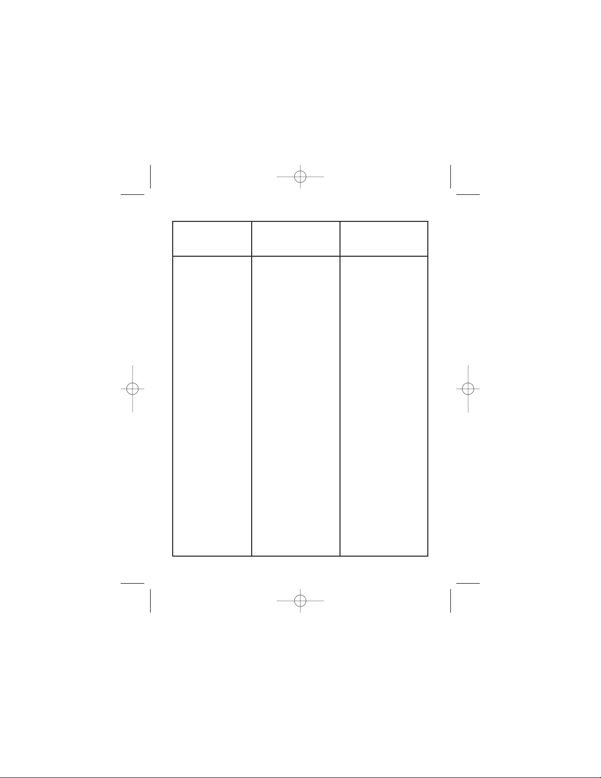
69
Problem Possible
Causes
Suggested
Solutions
Troubleshooting
Line fuse blows 1. Line fuses are
the wrong size.
2. Motor cable or
armature is shorted
to ground.
3. Nuisance
tripping caused by
a combination of
ambient conditions
and high-current
spikes (i.e.
reversing).
4. Field circuit is
open (shunt wound
motors only).
1. Check that line
fuses are correct
for motor size
(page 13).
2. Check motor
cable and armature
for shorts.
3. Add a blower to
cool the drive
components, or
decrease the duty
cycle of the
system.
4. Send drive to
Reliance Electric
repair department.
250-0287-rev2.qxd 3/12/01 10:27 AM Page 69
Page 78

70
Problem Possible
Causes
Suggested
Solutions
Troubleshooting
Line fuse does
not blow, but
motor does not
run
1. Speed adjust
potentiometer,
voltage external
reference signal, or
current external
reference signal
set to zero speed.
2. Speed adjust
potentiometer,
voltage or current
external reference
signal not
connected to drive
input properly;
connections are
open.
3. S2 is shorted to
S1.
4. Drive is in
current limit mode.
1. Increase the
speed adjust
potentiometer,
voltage, or current
setting.
2. Check
connections
to input. Verify that
connections are
not open.
3. Remove short.
4. Verify that motor
is not jammed.
Increase
CURRENT LIMIT
setting if it is set
too low.
250-0287-rev2.qxd 3/12/01 10:27 AM Page 70
Page 79
71
Problem Possible
Causes
Suggested
Solutions
Troubleshooting
Line fuse does
not blow, but
motor does not
run (cont.)
5. Drive is not
receiving AC line
voltage.
6. Motor is not
connected.
7. B1 not
connected to B3 (if
ST ART/STOP
pushbuttons are
not used).
8. Motor is stalled
because of
incorrect field
connections (shunt
wound motors
only).
5. Apply AC line
voltage to L1 and
L2.
6. Connect motor
to A1 and A2.
7. Connect B1 to
B3.
8. Verfiy proper
field connections.
250-0287-rev2.qxd 3/12/01 10:27 AM Page 71
Page 80

72
Problem Possible
Causes
Suggested
Solutions
Troubleshooting
Motor runs too
fast at set speed
1. MIN SPD and
MAX SPD settings
are too high.
2. Motor field
connections are
loose (shunt wound
motors only).
3. Motor is
demagnetized.
4. Tachometer
leads are reversed.
1. Recalibrate MIN
SPD and MAX
SPD.
2. Check motor
field connections.
3. Check for proper
braking technique
and method by
which power is
cycled.
4. Check
tachometer
connections.
250-0287-rev2.qxd 3/12/01 10:27 AM Page 72
Page 81

73
Problem Possible
Causes
Suggested
Solutions
Troubleshooting
Motor runs too
slow or too fast
1. Switches are set
incorrectly.
2. MIN SPD and
MAX SPD not
calibrated.
3. Motor field not
properly connected
(shunt wound
motors only).
4. TACH VOLTS
trimpot not
calibrated properly.
5. Motor is
demagnetized.
1. Verify all switch
settings.
2. Calibrate MIN
SPD and MAX
SPD.
3. Verify motor field
connections.
4. Recalibrate
TACH VOLTS
trimpot.
5. Check for proper
braking technique
and method by
which power is
cycled.
250-0287-rev2.qxd 3/12/01 10:27 AM Page 73
Page 82

74
Problem Possible
Causes
Suggested
Solutions
Troubleshooting
Motor will not
reach the
desired speed
Motor pulsates
or surges under
load
1. MAX SPD
setting is too low.
2. IR COMP setting
is too low.
3. Motor is
overloaded.
1. IR COMP is set
too high.
2. Motor “bouncing”
in and out of torque
limit.
1. Increase MAX
SPD setting.
2. Increase the IR
COMP setting.
3. Check motor
load. Resize the
motor if necessary.
1. Adjust the IR
COMP setting
slightly CCW until
the motor speed
stabilizes.
2. Make sure motor
is not undersized
for load; adjust
CURRENT LIMIT
trimpot.
250-0287-rev2.qxd 3/12/01 10:27 AM Page 74
Page 83

75Troubleshooting
Figure 20. DC3N Block Diagram
Block Diagram
250-0287-rev2.qxd 3/12/01 10:27 AM Page 75
Page 84

Terminal descriptions
Chassis drive terminals
L1 (TB501)
Hot terminal for AC line voltage.
L2/115 (TB501)
Neutral terminal for 115 VAC line voltage.
L2/230 (TB501)
Neutral terminal for 230 VAC line voltage.
F1, F2 (TB501)
Field coil connections (shunt wound motors only). Field
voltage is 100/200 VDC.
A1, A2 (TB501)
Connections to motor.
B1, B2, B3 (TB502)
Connections for START/STOP pushbuttons.
S1, S2, S3 (TB502)
Connections for speed adjust potentiometer or external
reference signal.
76 Troubleshooting
250-0287-rev2.qxd 3/12/01 10:27 AM Page 76
Page 85

T1, T2 (TB502)
Connections to optional external tachometer.
Enclosed drive terminals
L1 (terminal 1)
Hot terminal for AC line voltage.
L2/115 (terminal 2)
Neutral terminal for 115 VAC line voltage.
L2/230 (terminal 3)
Neutral terminal for 230 VAC line voltage.
F1, F2 (terminals 4 and 5)
Field coil connections (shunt wound motors only). Field
voltage is 100/200 VDC.
A1, A2 (terminals 6 and 7)
Connections to motor.
COM (terminal 8)
Circuit common (-) for external reference signal.
REF (terminal 9)
Signal (+) lead for external reference signal.
77Troubleshooting
250-0287-rev2.qxd 3/12/01 10:27 AM Page 77
Page 86

Reliance Electric Corporation hereby certifies that its
DC3N series drives have been approved to bear the “CE”
mark provided the conditions of approval (listed in Exhibit
“A”) have been met by the end user.
The DC3N series has been tested to the following test
specifications:
EN55011:1991 (emissions),
EN50082-1:1992 (immunity)
Compliance allows Reliance Electric’s DC3N series to bear
the CE mark.
The end user, as described herein, falls into one of two
categories:
1. The Consumer will deploy a stand-alone unit as an
integral, yet external, portion of the machine he/she
is operating.
2. The Original Equipment Manufacturer (OEM) will
implement the product as a component of the
machine being manufactured.
78
CE Compliance
250-0287-rev2.qxd 3/12/01 10:27 AM Page 78
Page 87

79CECompliance
Exhibit “A”
In addition to EMI/RFI safeguards inherent in the DC3N
series’ design, external filtering is required.
Reliance Electric requires the Corcom® filters listed in
Table 4. If the exact filter is not available, the
specifications are as follows:
L = (1.73 + 0.03) milliHenries.
C = (0.27 + 0.54) microFarads (X); 0.0055
microFarads (Y).
R = 330Kohms.
Rated current: 1.4 times maximum DC motor current.
Filter type: Balanced 2-section.
Table 5. Corcom® Filters
Nameplate Current of
Motor Wired Corcom© Filter
to the Drrive Part Number
0 to 4 amps 6VV1
4.1 to 13 amps 20VV1
The filters in Table 5 must be wired to the AC output of
the drive, as close to the drive as possible. The ground
connection from the filter must be wired to solid earth
ground (resistance less than 500 ohms); not machine
ground. This is very important!
250-0287-rev2.qxd 3/12/01 10:27 AM Page 79
Page 88

80 CE Compliance
If the end-user is using a CE-approved motor, the correct
filter from Table 5 is all that is necessary to meet the EMC
directives listed herein.
Armature Filters
If the end-user is not using a CE-approved motor, a
Reliance Electric CEXXMM filter must be deployed on the
output. XX is the rated current on the filter
The CE20MM is a Real-Pole Balanced-Pi 3-pole filter. If
the exact filter is not available, the specifications are as
follows:
L&L1=2*(0.8)milliHenries.
C&C1=2*(0.1) microFarads @ 400W VDC.
Rin = 0.1 ohm; Rout = 1.2 ohm.
Table 6. Armature Filters
Nameplate Current of
Motor Wired Reliance Electric© Filter
to the Drrive Part Number
0 to 4 amps CE04MM
4.1 to 13 amps CE20MM
250-0287-rev2.qxd 3/12/01 10:27 AM Page 80
Page 89

The filters in Table 6 must be wired to the DC output of
the drive, as close to the drive as possible. The ground
connection from the filter must be wired to solid earth
ground (resistance less than 500 ohms); not machine
ground. This is very important!
The end user must use the filtering listed in Exhibit A to
comply with CE. The OEM may choose to provide
alternative filtering that encompasses the Reliance Electric
drive and other electronics within the same panel.
The OEM has this liberty because CE is a machinery
directive. Whether or not every component in the OEM’s
machinery meets CE, the OEM must still submit his
machine for CE approval. Thus, no component must
necessarily meet CE within the machine, as long as the
OEM takes the necessary steps to guarantee the machine
does meet CE. By the same token, even if every
component in the OEM’s machine does meet CE, the
machine will not necessarily meet CE as a machine.
Use of CE-approved wiring practices, such as proper
shielding, and the filters listed in Exhibit A guarantee the
drive will meet EN55011 (1991 emissions standard) and
EN50082-1 (1992 immunity standard).
81CE Compliance
250-0287-rev2.qxd 3/12/01 10:27 AM Page 81
Page 90

Notes
250-0287-rev2.qxd 3/12/01 10:27 AM Page 82
Page 91

250-0287-rev2.qxd 3/12/01 10:27 AM Page 83
Page 92

U.S. Drives Technical Support
Tel: (1) 262.512.8176, Fax: (1) 262.512.2222, Email: support@drives.ra.rockwell.com, Online: www.ab.com/support/abdrives
Publication D2-3452-March 2001 Copyright © 2001 Rockwell Automation, Inc. All Rights Reserved. Printed in USA.
 Loading...