

Page 1
Installation and Operating Instructions
Bulletin 802T 4ĆCircuit Direct Opening Action Limit Switch
ATTENTION: To avoid electrical shock
and unintended operation of equipment,
disconnect all power to the limit switch and
the controlled equipment before
proceeding with any repair or adjustment of
the limit switch.
Overview
Bulletin 802T Direct Opening Action limit switches have been
designed for use in applications requiring control reliability
performance per ANSI B11.19 and in safety applications
when applied as shown in ISO 14119.
Limit switches are used in electrical control systems to sense
position. They are actuated by the predetermined motion of a
cam, machine component or piece part. These limit switches
are suitable for use in control systems requiring control
reliability performance or safety related performance per ISO
13849–1.
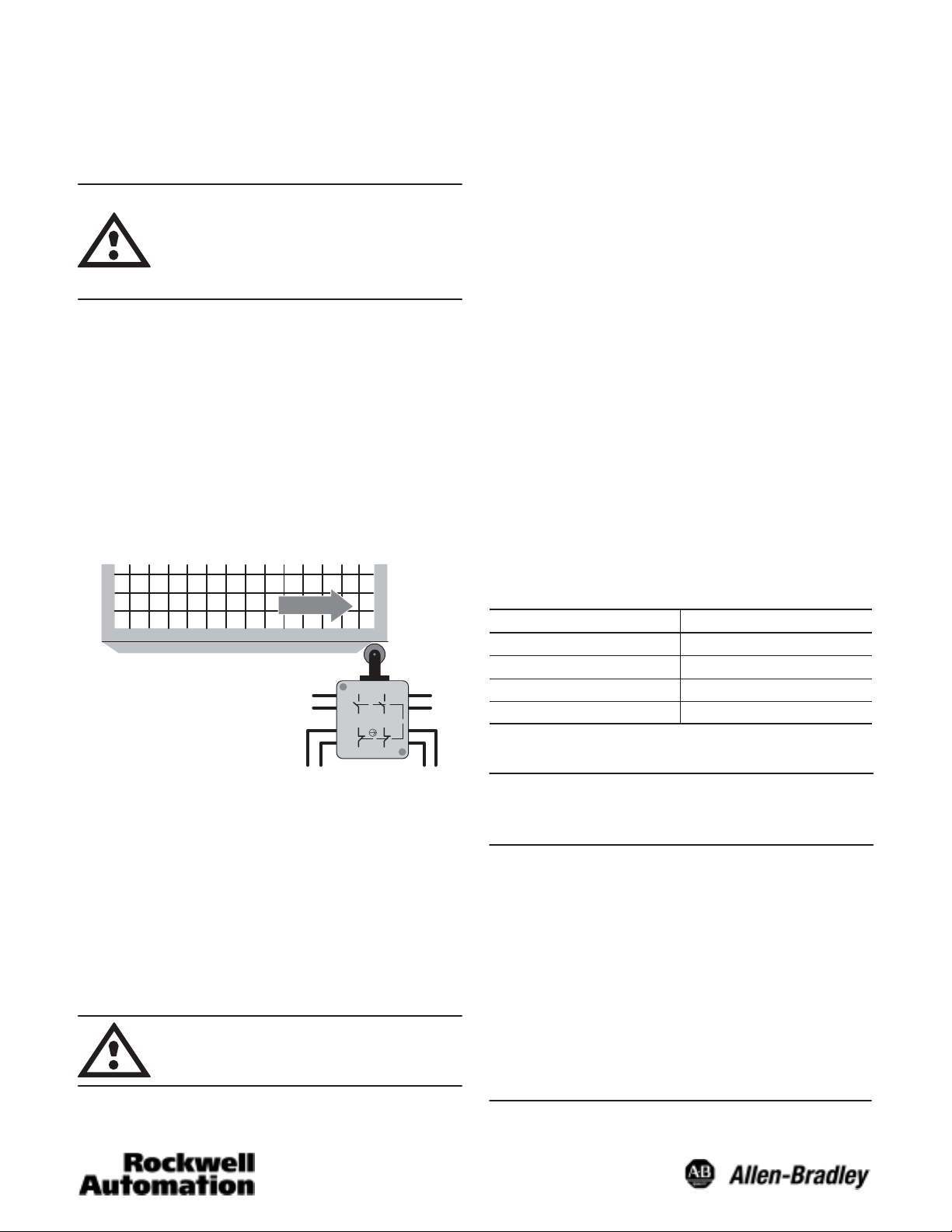
Typical Example of a Dual Channel Safety Application
Guard Closed
1
5
Aux 1
Channel 1
Before installation in a safety application, a risk assessment
should be performed to determine whether the specifications
of this device are suitable for foreseeable operational and
environmental characteristics of the machine which is to be
controlled. Only the normally closed set of contacts are
considered safety contacts. When applying these limit
switches in a safety system application, all applicable
standards for application should be followed. Operating
specifications must be followed and actuator must be
displaced beyond the point where Direct Opening Action
occurs. These devices are not to be used to directly control a
motor.
2
3
4
Safety
6
7
8
Aux 2
Safety
Channel 2
ATTENTION: Adjustable length lever
actuators should not be used in a safety
systems application.
General Data
S Safety Contacts: 2 Normally Closed
S Auxiliary Contacts: 2 Normally Open
S Enclosure Rating:
S NEMA 4, 6P, 12 and 13
S IP67
S Operating rate and speed Ê
S Lever Type: 150/minute @ 9m (30ft)/min Ë
S Top Push Roller: 150/minute @ 9m (30ft)/min Ì
S Side Push Roller: 150/minute @ 9m (30ft)/min Ì
S Operating Temperature (standard models) 18_C to 110_C
(0_F to 230_F)
S Short Circuit Protection: 10 amp slow or 15 amp fast
acting. Overload protection should be sized to load
requirements.
Mounting
Limit switches should be securely mounted using the
mounting holes provided. During installation, ensure that the
actuator will be displaced beyond the point where Direct
Opening Action takes place. Adjustable levers or rod
actuators should not be used in safety systems applications.
Description Tightening Torque
Terminal Screws 18inĆlb
Front to Rear Base 16 to 20inĆlb
Head Screws 12 to 18inĆlb
Lever Arm 25 to 36inĆlb
Wiring
Important: The contacts in each switching element
must have the same polarity. The circuit
diagram is shown on the nameplate.
The pressure type connector terminals in the base will accept
No. 12 AWG and smaller solid or stranded wire. For proper
tightening, it is suggested that nothing smaller than No. 18
AWG be used. Before inserting wire under the pressure
plates, strip the insulation approximately 3/8 inch. Tighten all
pressure plate terminals whether used or not, to avoid
interference with the switch cover.
After wiring has been completed, check that all wires are in
the wiring cavity of the terminal block so they will not interfere
with the switch when it is plugged into the terminal block.
Recheck all wiring terminal screws for tightness.
Note: For switches that have been factory wired, check wire
color and their position in the terminal block for proper
circuit hookup.
Ê Based on operation temperature of 68_F to 86_F.
Ë Using 802T-W1A operating lever.
Ì Using 30_ nonĆovertravel dog.
Page 2
S Grounding of switch should be achieved per National
Electric Code (NFPA 70) requirements. Grounding terminal
is located in the terminal block housing.
S Arrange control wiring according to terminal markings.
S Tighten terminal screws according to specifications.
S Only use insulated connectors.
Important: Pay close attention to the terminal
numbering on the terminal block when
wiring this switch. Terminals 1 and 2 or 5
and 6 are normally open contacts.
Terminals 3 and 4 or 7 and 8 are normally
closed contacts.
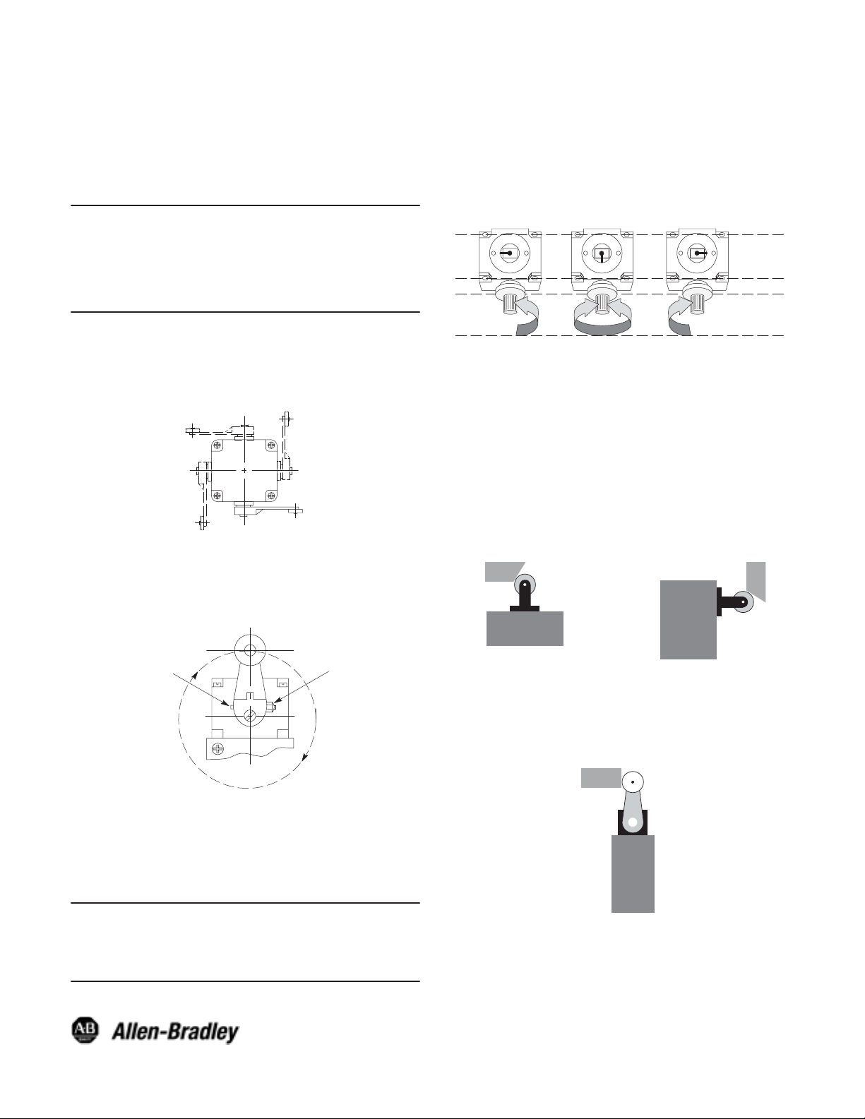
Actuator Head Positioning
The actuator head may be placed in any of four positions on
the switch body. Loosen the four captive screws. Place the
head in the desired position and securely retighten the four
screws (see figure below).
Step 1: Loosen the four head mounting screws and remove
the operating head from the switch body.
Step 2: Locate the plunger on the underside of the operating
head.
Step 3: Pull the plunger outward and rotate it in steps of 90_
to provide the operating mode desired. The
respective settings are shown in the figure below.
Plunger
Setting
Actuation
Required
CCW Only CW OnlyCW & CCW
Step 4: Make sure the plunger is pushed back inward and
the “O” ring is properly seated before the operating
head is reattached to the switch body.
Step 5: Securely retighten the operating head mounting
screws.
Step 6: Check for the desired actuation mode.
Methods of Actuation Examples
Lever Positioning
The lever on rotary actuated devices is adjustable to any
position through 360_ around the shaft. Loosen the nut, move
the lever to the desired position and securely retighten the nut
(see figure below).
Lock Pin
Nut
Changing Direction of Actuation
The switch action of lever operated limit switches may be
adjusted to operate with either a clockwise, a
counterclockwise or both directions movement of the shaft.
To change the actuation direction, follow the steps below:
Important: This procedure must be performed in a
clean environment to avoid the
introduction of foreign material into the
operating mechanism.
802T–DPD
Top Push Roller
30_ Non-Overtravel Dog
Vmax = 30ft/min @ actuator
F max = 150 cycles/min
802T–W1A 1.5I Long
90_ Non-Overtravel Dog
Vmax = 30ft/min @ actuator
F max = 150 cycles/min
802T–KPD
Side Push Roller
30_ Non-Overtravel Dog
802T–APD
Publication 75023–092–01(A)
September 2002
Printed in USA
 Loading...