

Page 1
Bulletin 802PR — Type LA and Type XA — Series C
IMPORTANT: SAVE THESE INSTRUCTIONS FOR FUTURE USE.
Prewired cable Threaded conduit
opening
Prewired
receptacle
Conduit coupler
(Millimeters)
(Inches)
(Millimeters)
Sensing Distance (inches)
Targ et
Release
Operate
Targ et
Square Target Size (x in Inches)
(Millimeters)
Half Hard Cold
Aluminum (Alloy #1100-H14)
Cold Rolled Low Carbon
Cold Rolled
(Millimeters)
Head On Sensing Distance (inches)
Stainless Steel (AISI 304)
Half Hard
Brass (Alloy 260 ASTM
Rolled Copper (ASTM-
Sensing Head Facing
Sensing Faces in Same Plane
3 in. minimum
2 in. minimum
Sensing
Face
Metal
Sensing
Face
Targ et
Targ et
Targ et
Metal
Metal
Sensing
Face
D
D
D
1/4 in. Clearance
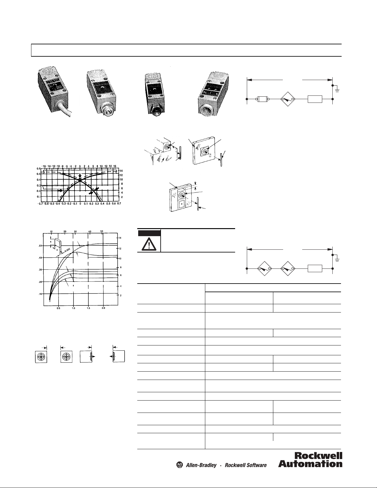
Figure 4a: Metal adjacent to one
side of head. Sensing distance D
increases approximately 2%.
Figure 4b: Metal su rrounds head.
Sensing distance D increases
approximately 10%.
Figure 4c: Metal surrounds switch. Sensing
distance D increases approximately 8%.
WARNING
If a hazardous condition can result from
unintended energization of this device, access to
the sensing area should be guarded.
Proximity
Switch
LOAD
Fuse
(if used)
(110/120V AC
L
1
L
2
LOAD
(110/120V AC
L
1
L
2
HAZARDOUS LOCATION SWITCHES — Switches for hazardous
locations meet Division 2; Class I Groups A, B, C, & D; Class II,
Groups F & G; and, Class III requirements. For additional
information refer to Publication GI-2.8 — A Summary of
National Electrical Code Requirements for Hazardous Locations.
Figure 1: Typical sensing characteristics
Effects of Target Size and Materials on Sensing Distance
Installation Instructions
Figure 4: Effects on nearby meta l surfaces on sensing distances.
CONNEC TION DIAGRAM
Figure 5: Typical wiring diagram
NOTE: To guard against the load remaining energized when the
switch is in an open condition, the minimum load release current
must be greater than the maximum leakage current of the
proximity switch.
GROUNDING — The Bulletin 802PR does not require a ground
connection. The load side of the110/120V AC source can be
grounded as indicated in the connection diagram.
SHORT CIRCUIT PROTECTION — A fuse is recommended in the
circuit to provide short circuit protection for the switch. Use a fast
acting Type KAW10 or KAX10 fuse.
SERIES CONNECTED SWITCHES —
Normally Open Fixed Output — Do not connect two or more
of the switches in series. Erratic operation may result.
Programmable Normally Open/Normally Closed Output
— Two switches can be connected in series with a load. For
proper operation, the operating load voltage must be less than or
equal to the minimum supply voltage less the sum of the onstate voltage drops across the series connected proximity
switches. The load will be energized when the OUTPUT LEDs of
both proximity switches are ON.
CONNEC TION DIAGRAM
WIRING — Connect the proximity switch and load as shown in
Figure 5 using AWG #18 through #14 wire (1.0/1.5mm
of the switch will be ON when the load is energized.
SPECIFICATIONS
Description
Operating voltage range 102…132V, 50/60 Hz 60…132V, 50/60 Hz
Figure 2: Typical sensing distance vs. target size for various metals
SPACING BETWEEN SWITCHES — When installing switches
side-by-side or face-to -face, the minimum spacings in Figure 3
should be maintained.
EFFECTS OF NEARBY METAL SURFACES ON SENSING
DISTANCES — The sensing distance will increase if the
proximity switch is installed so that metal is adjacent to the
Load current Max. continuous: 1 A to +40°C linearly derated to 0.5 A at +75°C
Max. leakage current (load off) 0.0065 A 0.0035 A
Max. voltage drop (load on) 7.5V
Operating temperature range -25…+75°C (-13…+167°F)
Max. operate time 25 ms 25 ms
Max. release time 35 ms 25 ms
Delay on power-up target present 20 ms, typical (no output occurs with target absent)
Sensing distance Steel: 0.525 in. +10% -5%. Refer to Figure 1
sensing head surfaces as illustrated in Figure 4.
Hysteresis (operate — release differential) 0.075 in. max.
Sensing distance drift with temperature ±5% 0…+75°C (32…167°F)
Max. sensing distance drift with voltage ±0.5% 102…132V ±1% 90…132V
Repeat accuracy (10 successive operation s) 0.001 in. max. deviation at constant temperature and supply voltage
Operating speed
(operations per minute)
2
). The LED
Output Mode
Fixed
Normally Ope n
Max. inrush: 10 A, 1 second max.
Min.: 0.025 A
Nonferrous metals: 0.25 in. typical
±10% -25…+75°C (-13…167°F)
1000 1200
Based on max. operate and release time
±5% +15…+50°C (59…122°F)
±10% -25…+75°C (-13…167°F)
±3% 60…132V
Programmable
Normally Open/Normally Closed
Page 2
PROGRAMMABLE OUTPUT SELECTION — The programmable
ATTENTION
Do NOT connect two or more Bulletin 802PR
switches in parallel. Erratic operation may
result.
Normally
closed
mode
Depress recessed rocker near
indicating line to change output mode
Normally
open
mode
Short Pin —
Connects to Terminal 1
Short Pin —
Connects to Terminal 2
Long Pin — Not used
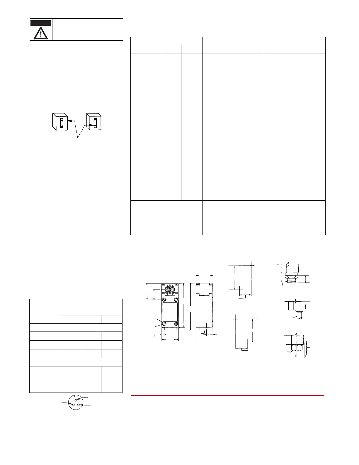
41
(1-5/8)
26
(1-1/84)
109
(4-11/32)
117
(4-5/8)
42
(1-21/32)
6 (15/84)
dia. holes
Front mounting
US (1-5/32 x 2-11/32)
DIN (30 x 60)
6 (15/84)
41
(1-5/8)
1/2 in.-14 NPT
Inside threads
Threaded Con duit Openin g
15
(19/32)
(1-5/32)
(2-11/32)
Rear mounting hole pattern
front view
2 #10-32 tapped holes
9.5 (3/8) deep
30
(1-5/32)
60
(2-11/32)
Front mounting hole pattern
front view
2 holes for #10 or M5 screws
22
(13/16)
7/8 in.-16N
outside threads
Prewired cable
1 in. hub
1/2 in.-14 NPT
inside threads
15
(19/32)
Conduit Coupler
10 (13/32) dia.
16 AWG
2 conductor
STO cable
Prewired receptacle
16
(5/8)
Typ e LA onl y.
Also available with ISO 20- 1.5 threads.
N.O./N.C. proximity switch is factory preset in either the normally
open or normally closed output mode.
To change the switch output mode use the following instructions.
1. Remove the lower legend plate on the front of the switch.
2. A line on the recessed rocker indicates the output mode of
the switch.
3. To change the output, depress the recessed rocker of the
switch with a pointed tool.
Note: Do not use a tool whose point could break and jam the
switch.
4. Replace the lower legend plate.
To return the output mode to its original setting, simply reverse
the above procedure. The OUTPUT LED will be ON when the
switch output is conducting.
HARD WIRED CONTACTS — When hard wired contacts are
connected in parallel with the Bulletin 802PR, a surge suppressor
MUST BE connected in parallel with the load. Surge suppression is
not required when hard wired contacts are connected in series
with the load. For recommended surge suppressors for various
devices, refer to publication 802PR-2.1 product data.
NOTE: Hard wired contacts that are operating in series or parallel
with the Bulletin 802PR Type LA or Type XA will cause a delay of
approximately 200 ms. This power-up delay will reduce the
maximum number of operations per minute and may result in a
momentary de-energization of the load.
CONDUIT CO UPLED SWITCHES — Threaded conduit opening
bases are suitable for use with flexible conduit. Conduit coupler
bases are suitable for use with both flexible conduit and rigid
conduit. Both bases connect to 1/2 in.-14 NPT threaded conduit.
Switches with a “S6” suffix in their catalog number are suitable
for connection to ISO 20-1.5 threaded conduit.
PREWIRED CABLE SWITCHES — These switches include a
prewired cable for connection directly into a junction box. The
cable is a two conductor, oil resistant thermoplastic (STO).
PREWIRED RECEPTACLE SWITCHES — These switches include
a prewired receptacle suitable for use with the connector-cable
assemblies listed in the table below. Figure 6 indicates which two
pins of the receptacle are wired internally to terminals 1 and 2.
The third pin is not used.
Manufacturer
Standard Color Code (green, black, white)
Brad Harrison 40901 40902 40903
Joy X8984-3 8984-4 8984-5
CAM-LOK E2057-624 E2057-625 E2057-626
Automotive Color Code (green, red, red)
Brad Harrison 40958 40959 40960
Joy X8984-13 X8984-14 X8984-15
CAM-LOK E2057-824 E2057-825 E2057-826
Figure 6: End view of prewired receptacle
Connector Cable (supplied by user)
Connector Cable Part Numbers
3-ft cable 6-ft cable 12-ft cable
TROUBLESHOOTING GUIDE — The following guide provides basic troubleshooting information for installation and use of the proximity
switch. If a problem occurs, attem pt to determine the POSSIBLE CAUSE as listed. Apply the suggested SOLUTION.
NOTE: The switch may continue to operate even if the LED (will not light) is damaged.
Output LED
Symptom
Load wil l not
energize
OFF OFF A. Power supply off. A. Apply power.
OFF ON B. Incorre ct voltage applied B. Apply correct voltage.
Possible Cause SolutionN.O. N.C.
OFF OFF C. Broken wires or loose connections. C. Repair wiring or tighten loose connections.
OFF ON D. Improper wiring. D. Recheck con nection diagrams. Rewire
OFF N/A E. Target too small or o ut of sensing range. E. Increase ta rget size of move target or switch
N/A OFF F. Target or metal object within sensing range. F. Remove target or metal object. Refer to
OFF OFF G. Two or more proximity switches placed too
close together.
accordingly.
within sensing range.
EFFECTS OF NEARBY METAL SURFACES.
G. Move sensing faces of switches apart. Refer
to SPACING BETWEEN SWITCHES.
ON ON H. Load device faulty or incorrect. H. Replace load or size load correctly.
Load wil l not
de-energize
ON N/A A. Target or metal object within sensing range. A. Remove target or metal object. Refer to
N/A ON B. Target too small or o ut of sensing range. B. Increase target size of move target or switch
ON ON C. Two or more proximity switches placed too
close together.
ON OFF D. Improper wiring. D. Recheck connection diagrams. Rewire
EFFECTS OF NEARBY METAL SURFACES.
within sensing range.
C. Move sensing faces of switches apart. Refer
to SPACING BETWEEN SWITCHES.
accordingly.
OFF OFF E. Load device faulty or incorrect. E. R eplace load or size load correctly.
Load energizes and
de-engerizes
intermittently
Programmable N.O./N.C. switches have two LEDs. The POWER LED will be ON when power is applied.
N/A — Not Applicable.
ON & OFF intermittently A. Broken wires or loose connections. A. Repair wiring or tighten loose connections.
B. Target fluctuates in and out of sensing
range and hysteresis zone.
C. Two or more proximity switches placed too
close together.
B. Stabilize target within the sensing range.
Refer to SPECIFICATIONS — Hysteresis.
C. Move sensing faces of switches apart. Refer
to SPACING BETWEEN SWITCHES.
MOUNTING DIMENSIONS — Dimensions shown in mm (inches).
www.rockwellautomation.com
Power, Control and Information Solutions Headquarters
Americas: Rockwell Automation, 1201 South Second Street, Milwaukee, WI 53204-2496 USA, Tel: (1) 414.382.2000, Fax: (1) 414.382.4444
Europe/Middle East/Africa: Rockwell Automation NV, Pegasus Park, De Kleetlaan 12a, 1831 Diegem, Belgium, Tel: (32) 2 663 0600, Fax: (32) 2 663 0640
Asia Pacic: Rockwell Automation, Level 14, Core F, Cyberport 3, 100 Cyberport Road, Hong Kong, Tel: (852) 2887 4788, Fas: (852) 2508 1846
802PR-IN002A-EN-P 77050-001-01
July 2013 Printed in Dominican Republic
 Loading...