

Page 1
Installation and Operating Instructions
IMPORTANT: SAVE THESE INSTRUCTIONS FOR FUTURE USE.
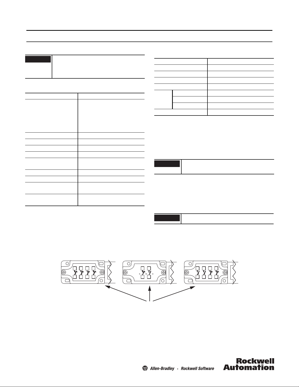
Typical Wiring Diagrams
4 N.C.
41 31 21
11
423222
12
2 N.O. 2 N.C.
43 33 21
11
44 34 22 12
Same polarity this side of block
1 N.O. 1 N.C.
11 23
12 24
IMPORTANT
IMPORTANT
Bulletin 802K DIN 50041 IEC/Large Metal Body Standard Limit Switch
IMPORTANT
Installation of Allen-Bradley products should be in
accordance with local and/or national codes.
Servicing energized industrial control equipment can be
hazardous if not in accordance to recommended safety
procedures.
Specifications
AC/DC Designation A600; Q600
AC/DC Utilization Category Alternating current: AC15 (50/60 Hz)
Ue (V): 120 240 500 600
le (A): 6 3 1.4 1.2
Direct current: DC13
Ue (V): 125 250 500 600
le (A): 0.55 0.27 0.13 0.1
Max. Fusing Rate 10 A fast acting
Impulse Voltage (Uimp) 2500V
Enclosure Protection IP66
Pollution Degree 3
Storage/Operating
Temperature
Direct Opening Action Normally closed only
Conductor Sizes Use copper conductors only
Stranded 0.75…2.5 mm2 (0.02…0.09 in.2)
Solid 0.75…2.5 mm2 (0.02…0.09in.2)
-25…+65 °C (-13…+149 °F)
(18…14 AWG)
(18…16 AWG)
Torque/Mounting
Location Torque
Heads 1.2 N•m (0.86 lb•ft)
Covers 1.6 N•m (1.18 lb•ft)
M5 Mounting 2.5…3.0 N•m (1.84…3.21 lb•ft)
Wire Clamp 0.9…1.0 N•m (0.66…0.74 lb•ft)
Lever
Clamp
M5 Hex Screw 1.8 N•m (1.33 lb•ft)
M3/M4 Hex Screw 1.5 N•m (1.11 lb•ft)
Adj. Lever Screw 1.0 N•m (0.74 lb•ft)
Conduit 1.0 N•m (0.74 lb•ft)
Rotating Operator Heads
When rotating operator heads, follow these steps:
1. Loosen the head mounting screws and remove the operating
head from the switch enclosure.
Internal operator head components can become dislodged when removing operator heads. Use caution
during removal and assembly.
2. Orient the operator head in one of the four positions offered.
Make sure the loose parts are positioned correctly before
affixing the operator head to the switch enclosure.
3. Tighten the four screws per the recommended torque
specifications above.
Check for switch operation with a continuity indicator
before placing product in service.
Page 2
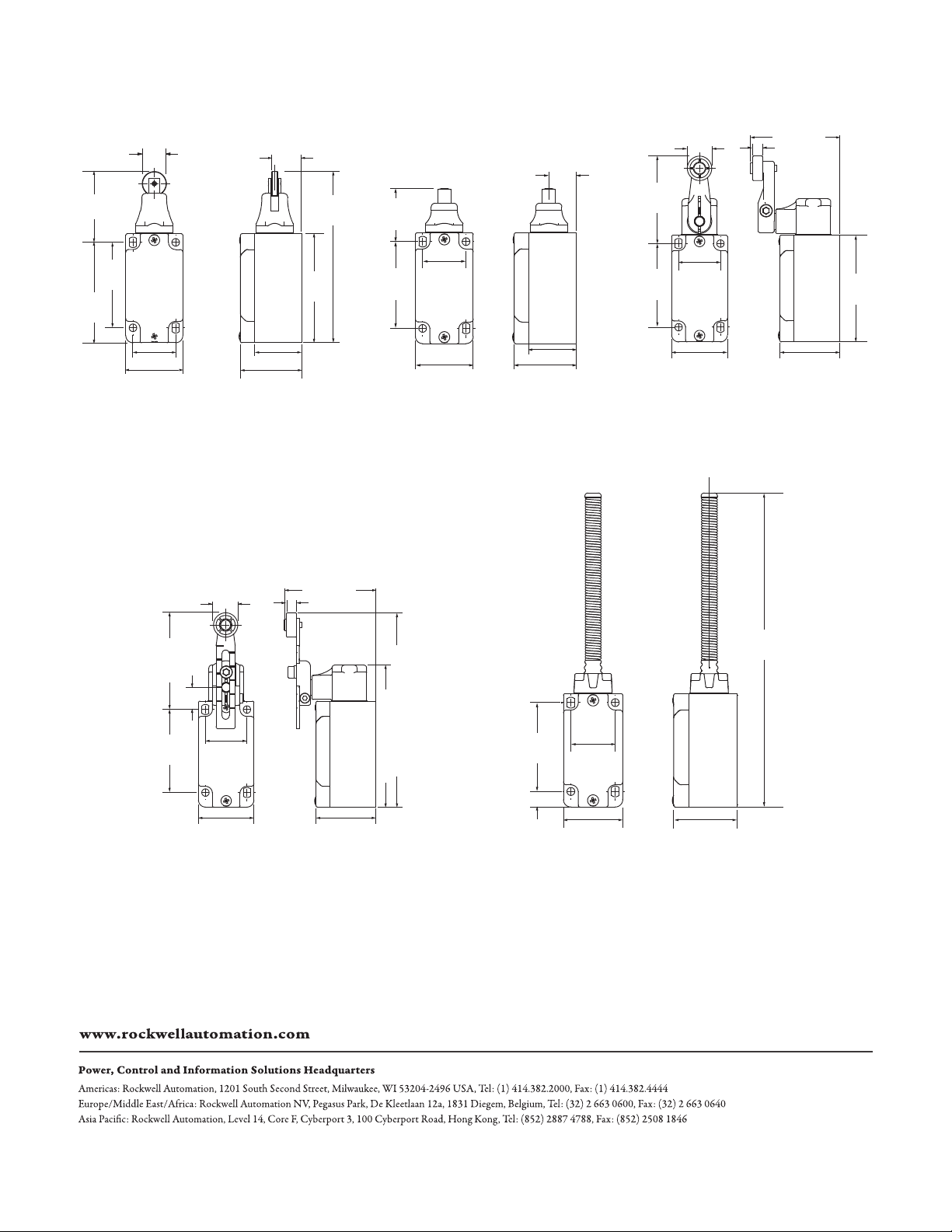
Open Conduit Dimensions [mm (in.)]
33 (1.29)
60
(2.36)
30 (1.18)
40 (1.57)
36.6
(1.44)
19
(0.74)
43 (1.69)
Roller Plunger Dome Plunger Short Lever
Adjustable Lever Spring Rod
48
(1.88)
70.5
(2.76)
60
(2.36)
17 (0.66)
Dia.
30 (1.18)
40 (1.57)
21
(0.82)
33 (1.29)
43 (1.69)
76.5
(3.01)
118
(4.64)
63
(2.48)
60
(2.36)
18 (0.7)
Dia.
30 (1.18)
40 (1.57)
64 (2.51)
7 (0.27)
43 (1.69)
133
(5.23)
85
(3.34)
Max.
(0.62)
60
(2.36)
16
17 (0.66)
Dia.
30 (1.18)
40 (1.57)
64 (2.51)
7 (0.27)
43 (1.69)
103 (4.05)
211
(8.3)
30 (1.18)
60
(2.36)
172 (6.77) Max. Extension
11 (0.43)
40 (1.57)
43 (1.69)
10000237915 Ver 01
June 2012
Copyright © 2012 Rockwell Automation, Inc. All Rights Reserved.
 Loading...