

Page 1
Installation and Operating Instructions
2
21
Bulletin 802B Compact Limit Switch
IMPORTANT: SAVE THESE INSTRUCTIONS FOR FUTURE USE.
This publication does not include specifications, dimensions, and other installation considerations.
Refer to the product catalog pages for additional information.
WARNING: To avoid electrical shock and/or unintended operation of equipment, disconnect all power to the limit
!
switch and the controlled equipment before proceeding with any repair or adjustment of the limit
switch.
Overview
Limit Switches are used in electrical control systems to sense
position. They are actuated by the predetermined motion of a
cam, machine component, or piece part. This mechanical
motion is then converted to an electrical signal through the
actuation of a set of contacts. These signals can be used in
the control circuits of solenoids, control relays, and motor
starters to control the operation of conveyors, hoists,
elevators, machine tools, etc. They are not to be used to
directly control a motor.
General Data
• Enclosure Rating: NEMA 1,3,4,6,12,13 and IP67
• Mechanical Life: Approx. 10,000,000 operations Ê
• Electrical Life: Approx. 200,000 operations (3A 250V AC,
resistive load) Ê
• Operating Speed
G Top Push: 0.1mm to 0.5m per second
G Side Rotary: 1mm to 1m per second
• Operating Frequency:
G Mechanical: 120 operations/minute
G Electrical: 30 operations/minute
• Operating Temperature: –10°C to 70°C (14°F to 158°F)
with no icing
• Short Circuit Protection: Quick blow fuse suitable for rated
current is recommended.
Ê Life expectancy has been calculated at an operating temperature
of 5°C to 35°C (41°F to 95°F) and an operating humidity of 40% to
70%.
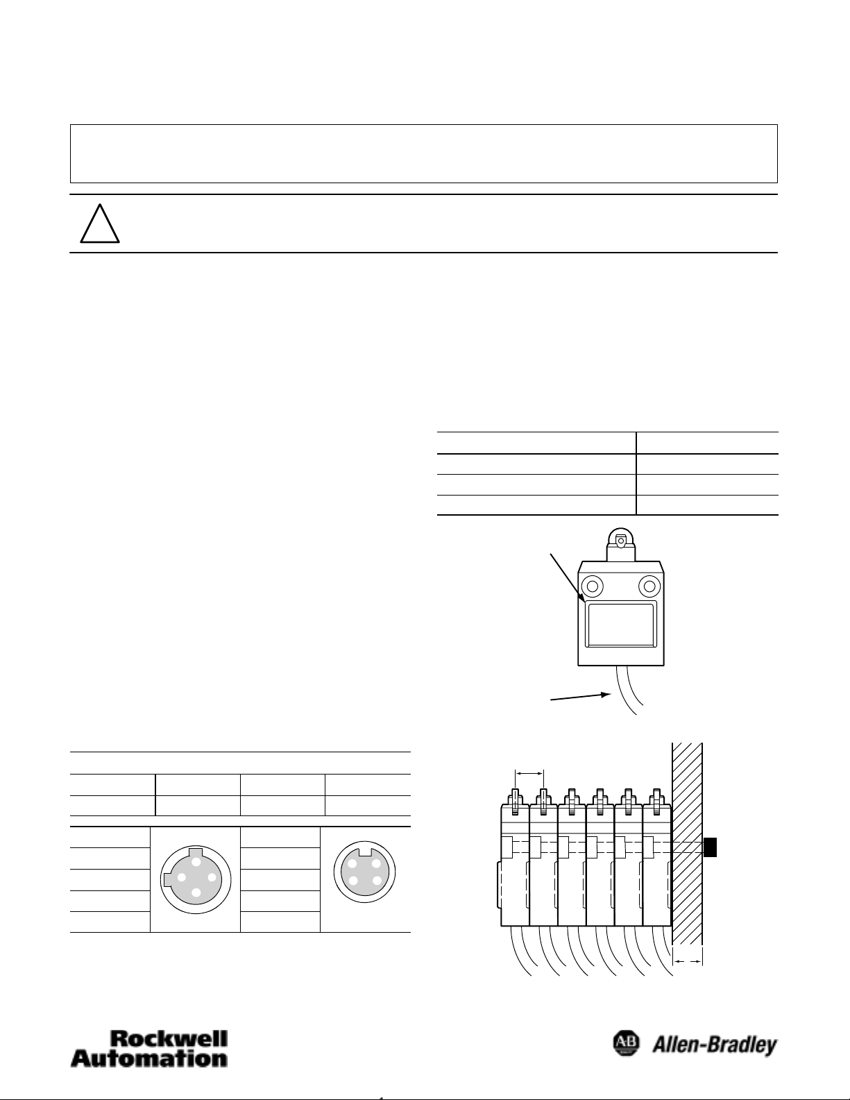
Wiring
PreĆLeaded Models
COM NO NC G
Black Blue Brown Green/Yellow
the bolt heads. The use of M5 Cap Screws, (Hex head), and
washers is recommended. Mounting bolts should be torqued
to a value between 4.90 and 5.88 Nm. These units have been
designed to enable gang mounting. In the case of ganged
mounting, the installer should fit the convex part of the gang
mount guide into the concave guide of the adjacent switch. A
maximum of six switches may be ganged. Special units that
have been designed for panel mounting will be provided with
a threaded head. These switches will also have washers and
a mounting nut included with the switch.
Hardware
Head mounting screw 0.78 to 0.88 N@m
Side rotary shaft bolt 4.90 to 5.88 N@m
Unit mounting screw 4.90 to 5.88 N@m
GangĆmounting guide
(convex front and
concave rear)
45mm
bend radius
16mm
Torque
Mounting Panel
AC QD Pin-out: DC QD Pin-out:
Pin 1 = Common
Pin 2 = N/O
Pin 3 = N/C
Pin 4 = Grnd. Pin 4 = N/C
2
3
4
1
Pin 1 = N/O
Pin 2 = Common
Pin 3 = Grnd.
Mounting
Units should be mounted using the mounting holes provided.
These mounting holes are counter boarded to help contain
21
4
3
Male Receptacle
6mm
Page 2
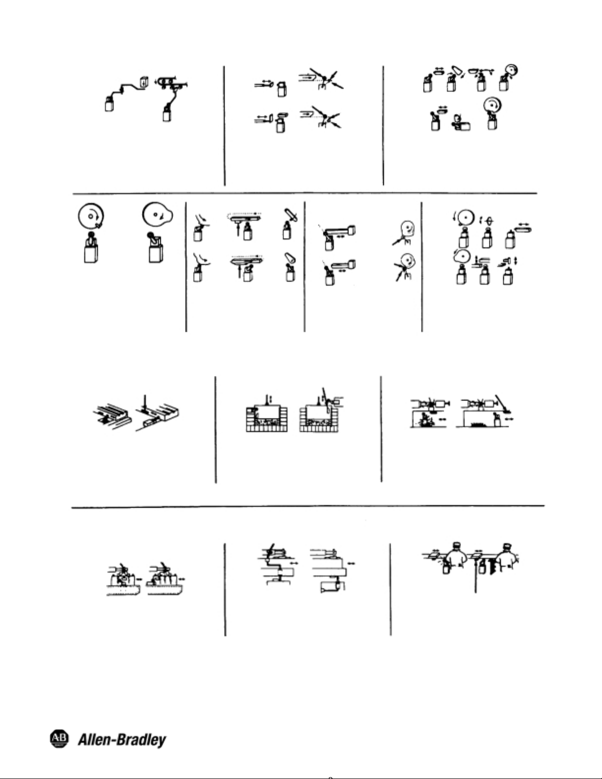
Actuator Consideration
Wrong
Limit switches are designed for proper performance with
the actuators with which they are supplied.
Supplementary actuators should not be used unless the
limit switches are specifically designed for them.
Wrong Right
Where relatively fast motions are involved
cam arrangements should be such that
the actuator does not receive a severe
impact. Cams should be designed such
that the limit switch will be held operated
long enough to operate relays, valves, etc.
Wrong
Free Position
Wrong
Free Position
Right
Operating mechanism for limit switches should be so
designed that under any operating or emergency
conditions the limit switch is not operated beyond its
overtravel limit position. A limit switch should not be used
as a mechanical stop.
Wrong
Overriding Cam
Right
Overriding Cam
Cam or dog arrangements should be such
that the actuator is not suddenly released
to snap back freely.
Wrong
Right
Interference
Wrong
Right
Actuator
Free Position
A limit switch actuator must be allowed to
move far enough for positive operation of
the contacts.
End of
Overtravel
Cam
Wrong
Cam
Right
End of
Overtravel
Operated
Position
Wrong
Operating
Position
Operating
Position
Wrong
NonĆOverriding
Right
NonĆOverriding
For limit switches with lever actuators, the actuating
force should be applied as nearly perpendicular to the
lever as practical and perpendicular to the shaft axis
about which the lever rotates.
Wrong
Right
Right
Operated
Position
For limit switches with pushrod actuators
the actuating force should be applied as
nearly as possible in line with the pushrod
axis.
Location and Installation
Cam
Wrong Right
Limit switches should be mounted rigidly and in
readily accessible locations with suitable
clearances to permit easy service and replacement
when necessary. Cover plates should face the
maintenance access point.
Wrong Right
Limit switches should not be submerged in or
splashed with oils, coolants or other liquids.
NonĆoverriding
Cam
Wrong Right
Limit switches should not be used in locations
where temperature or atmosphere conditions are
beyond those for which they have been specifically
designed.
Wrong Right
The location of oiltight limit switches and the method of
connecting them should be such that condensation in the
conduit cannot enter the switch enclosure.
NonĆoverriding
Cam
Wrong Right
Limit switches should be placed in locations where
machining chips do not accumulate under normal
operating condictions.
Wrong Right
NonĆoverriding
Cam
Limit switches should be mounted in locations
which will prevent false operation by normal
movements of operator or machine components.
Visit our web site at:
http://www.ab.com/sensors
Publication 75043–001–01(B)
February 2001
Printed in Japan
 Loading...