

Page 1

Installation Instructions
OneGear™ MV SMC Flex Solid-State Motor Controller
Publication Number 7760-IN001B-EN-P
Page 2

Important User Information
IMPORTANT
Read this document and the documents listed in the Additional Resources section about installation, configuration, and
operation of this equipment before you install, configure, operate, or maintain this product. Users are required to
familiarize themselves with installation and wiring instructions in addition to requirements of all applicable codes, laws,
and standards.
Activities including installation, adjustments, putting into service, use, assembly, disassembly, and maintenance are required
to be carried out by suitably trained personnel in accordance with applicable code of practice.
If this equipment is used in a manner not specified by the manufacturer, the protection provided by the equipment may be
impaired.
In no event will Rockwell Automation, Inc. be responsible or liable for indirect or consequential damages resulting from the
use or application of this equipment.
The examples and diagrams in this manual are included solely for illustrative purposes. Because of the many variables and
requirements associated with any particular installation, Rockwell Automation, Inc. cannot assume responsibility or
liability for actual use based on the examples and diagrams.
No patent liability is assumed by Rockwell Automation, Inc. with respect to use of information, circuits, equipment, or
software described in this manual.
Reproduction of the contents of this manual, in whole or in part, without written permission of Rockwell Automation,
Inc., is prohibited.
Throughout this manual, when necessary, we use notes to make you aware of safety considerations.
WARNING: Identifies information about practices or circumstances that can cause an explosion in a hazardous environment,
which may lead to personal injury or death, property damage, or economic loss.
ATTENTION: Identifies information about practices or circumstances that can lead to personal injury or death, property
damage, or economic loss. Attentions help you identify a hazard, avoid a hazard, and recognize the consequence.
Identifies information that is critical for successful application and understanding of the product.
Labels may also be on or inside the equipment to provide specific precautions.
SHOCK HAZARD: Labels may be on or inside the equipment, for example, a drive or motor, to alert people that dangerous
voltage may be present.
BURN HAZARD: Labels may be on or inside the equipment, for example, a drive or motor, to alert people that surfaces may
reach dangerous temperatures.
ARC FLASH HAZARD: Labels may be on or inside the equipment, for example, a motor control center, to alert people to
potential Arc Flash. Arc Flash will cause severe injury or death. Wear proper Personal Protective Equipment (PPE). Follow ALL
Regulatory requirements for safe work practices and for Personal Protective Equipment (PPE).
Allen-Bradley, Rockwell Software, Rockwell Automation, and TechConnect are trademarks of Rockwell Automation, Inc.
Trademarks not belonging to Rockwell Automation are property of their respective companies.
Page 3

Equipment Overview
Transportation and Handling
Equipment Installation
Table of Contents
Chapter 1
Overview . . . . . . . . . . . . . . . . . . . . . . . . . . . . . . . . . . . . . . . . . . . . . . . . . . . . . . . . . . 3
Chapter 2
Unpacking and Inspecting . . . . . . . . . . . . . . . . . . . . . . . . . . . . . . . . . . . . . . . . . . 5
Cabinet Handling Instructions. . . . . . . . . . . . . . . . . . . . . . . . . . . . . . . . . . . . . . 6
Overhead Lifting Method. . . . . . . . . . . . . . . . . . . . . . . . . . . . . . . . . . . . . . . 6
Rod or Pipe Rollers . . . . . . . . . . . . . . . . . . . . . . . . . . . . . . . . . . . . . . . . . . . . 8
Fork Lift Truck . . . . . . . . . . . . . . . . . . . . . . . . . . . . . . . . . . . . . . . . . . . . . . . . 8
Shipping Skid Removal . . . . . . . . . . . . . . . . . . . . . . . . . . . . . . . . . . . . . . . . . 8
Chapter 3
Removal of Overhead Lifting Brackets and Channels . . . . . . . . . . . . . . . . . 9
Opening the Front Medium Voltage Doors of the Converter Cabinet . . 9
Remove Medium Voltage Front Cover. . . . . . . . . . . . . . . . . . . . . . . . . 10
Disconnect Fiber Optic Cables to Converter Roll-out Modules . . . . . . 10
Disconnect Flexible Links . . . . . . . . . . . . . . . . . . . . . . . . . . . . . . . . . . . . 12
Disconnect Current Loop Wires . . . . . . . . . . . . . . . . . . . . . . . . . . . . . . 12
Disconnect Mechanical Fastening of Converter Modules . . . . . . . . 13
Install Converter Roll-out Module Ramp . . . . . . . . . . . . . . . . . . . . . . . . . . 14
Install Converter Roll-out Module Pull Handle. . . . . . . . . . . . . . . . . . . . . 15
Removal of Lifting Provisions . . . . . . . . . . . . . . . . . . . . . . . . . . . . . . . . . . . . . 16
Install the Converter Cabinet . . . . . . . . . . . . . . . . . . . . . . . . . . . . . . . . . . . . . 17
With Back Access . . . . . . . . . . . . . . . . . . . . . . . . . . . . . . . . . . . . . . . . . . . . 17
Without Back Access . . . . . . . . . . . . . . . . . . . . . . . . . . . . . . . . . . . . . . . . . 19
Inter-Cabinet Connections . . . . . . . . . . . . . . . . . . . . . . . . . . . . . . . . . . . . . . . 19
Floor Anchoring . . . . . . . . . . . . . . . . . . . . . . . . . . . . . . . . . . . . . . . . . . . . . . . . . 21
Installation of Power Bus Bushings . . . . . . . . . . . . . . . . . . . . . . . . . . . . . . . . 21
Install Power Bus Bushing Inserts . . . . . . . . . . . . . . . . . . . . . . . . . . . . . 22
Connect Power Bus to Switchgear Risers . . . . . . . . . . . . . . . . . . . . . . . 23
Install Lower Bus Links in the Converter Cabinet. . . . . . . . . . . . . . . 24
Installation of Barriers . . . . . . . . . . . . . . . . . . . . . . . . . . . . . . . . . . . . . . . . . . . . 27
Ground Bus Linking . . . . . . . . . . . . . . . . . . . . . . . . . . . . . . . . . . . . . . . . . . . . . 28
Electromechanical Interlock . . . . . . . . . . . . . . . . . . . . . . . . . . . . . . . . . . . . . . 29
OneGear Standard Plenum
General Reference
Chapter 4
Assemble Standard Plenum to Cabinetry. . . . . . . . . . . . . . . . . . . . . . . . . . . 31
Appendix A
Torque Requirements . . . . . . . . . . . . . . . . . . . . . . . . . . . . . . . . . . . . . . . . . . . . 37
Rockwell Automation Publication 7760-IN001B-EN-P - June 2013 1
Page 4

Table of Contents
Notes:
2 Rockwell Automation Publication 7760-IN001B-EN-P - June 2013
Page 5
Equipment Overview
Incoming Line Unit
Main Unit
Converter Cabinet
Bypass Unit
650 mm
650 mm
1500 mm
650 mm
Chapter 1
Overview
The OneGear™ MV SMC controller family consists of the following
configurations:
• Bul. 7760 – Retrofit Controller
• Bul. 7761 – OEM Controller (converter cabinet)
• Bul. 7762 – Complete Controller utilizing vacuum contactors
• Bul. 7763 – Complete Controller utilizing vacuum breakers.
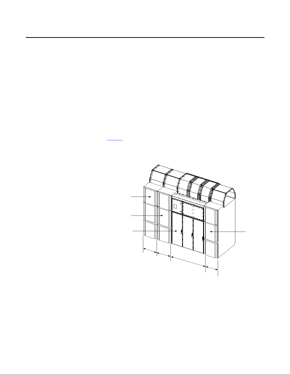
Figure 1
shows an overview of a typical Bulletin 7762/7763 controller complete
with incoming line unit. Refer to project documentation for specific
configuration details and dimensions.
Figure 1 - Typical Bulletin 7762/7763 OneGear MC SMC Controller
The Incoming Line Cabinet, Main Cabinet, and Bypass Cabinet are switch-gear
cabinets and are referred to as such throughout the remainder of this document.
All cabinets are shipped individually. This document describes the handling and
installation of the converter cabinet and the interconnections with the adjacent
switchgear cabinets.
Installation and connection instructions for switchgear cabinets, that are adjacent
to each other is covered by the respective manufacturer’s documentation and is
not included in this document.
Rockwell Automation Publication 7760-IN001B-EN-P - June 2013 3
Page 6

Chapter 1 Equipment Overview
Notes:
4 Rockwell Automation Publication 7760-IN001B-EN-P - June 2013
Page 7

Transportation and Handling
IMPORTANT
IMPORTANT
Chapter 2
Unpacking and Inspecting
Before leaving the factory, the controller has been tested mechanically and
electrically. Immediately upon receiving the controller, remove the packing and
check for possible shipping damage. Report any damage immediately to the
claims office of the carrier.
After unpacking, check the items received against the Bill of Lading to ensure
that the nameplate description of each item agrees with the material ordered.
Inspect the controller for physical damage as stated in the Rockwell Automation
Conditions of Sale.
All claims for breakage and damage, whether concealed or obvious, must be
made to the carrier by the customer as soon as possible after receipt of the
shipment. Rockwell Automation will render reasonable assistance in the
securing of adjustment for such damage claims.
Remove all packing material, wedges or braces from within the controller. If any
part of the equipment will not be installed when it is unpacked, it should be
stored in a clean dry place. The storage temperature must be between
-20...75 °C(-4...167° F) with a maximum humidity of 95% non-condensing.
The controller sections are shipped on wooden skids bolted to the cabinetry.
Lifting brackets are installed at the top corners of the cabinetry. The controller
sections must be maintained in the upright position during any handling.
ATT EN TI ON : Ensure that the load rating of all lifting equipment is sufficient to
safely raise the controller sections. Refer to the packing slip for shipping
weights.
Round rollers can be used to assist in moving the equipment to the installation
site. Once at the final site, rollers can be used to place the sections in their desired
position.
ATT EN TI ON : Use either a forklift or the pipe rolling technique for positioning
purposes to ensure that the equipment is not scratched, dented or damaged.
Stabilize the controller during handling to guard against tipping and injury to
personnel.
Customer installation duties must be performed correctly. Errors can cause
delays in commissioning or damage to the equipment.
Rockwell Automation Publication 7760-IN001B-EN-P - June 2013 5
Page 8

Chapter 2 Transportation and Handling
Cabinet Handling Instructions
When lifting the 1500 mm wide converter cabinet, the lifting instructions
specified below must be followed.
WARNING: Do not pass cables or ropes through support holes. Always use
load-rated shackles or safety hooks in support holes. The legs of swing must not
exceed 45° from vertical.
Overhead Lifting Method
1. Verify that the front/back lifting channels and the middle cosmetic
channels are all installed and that the connecting hardware is tightened to
the cabinet.
2. Verify that the four lifting clips have corresponding internal lifting clips
installed and connected. Lifting clip holes are 30 mm.
3. Figure 2
different depending on customers’ decision and availability of the lifting
hardware. Verify shipping weight and capacity of lifting equipment.
4. The angle between the slings (Figure 2
more (70° is ideal).
is only for lifting demonstration purpose. The lifting parts may be
) and horizontal must be 45° or
5. The centre to centre distance of the two lifting points of the lifting angle or
beam is to be 1500 mm +/- 150 mm (60” +/- 6.0”).
6 Rockwell Automation Publication 7760-IN001B-EN-P - June 2013
Page 9
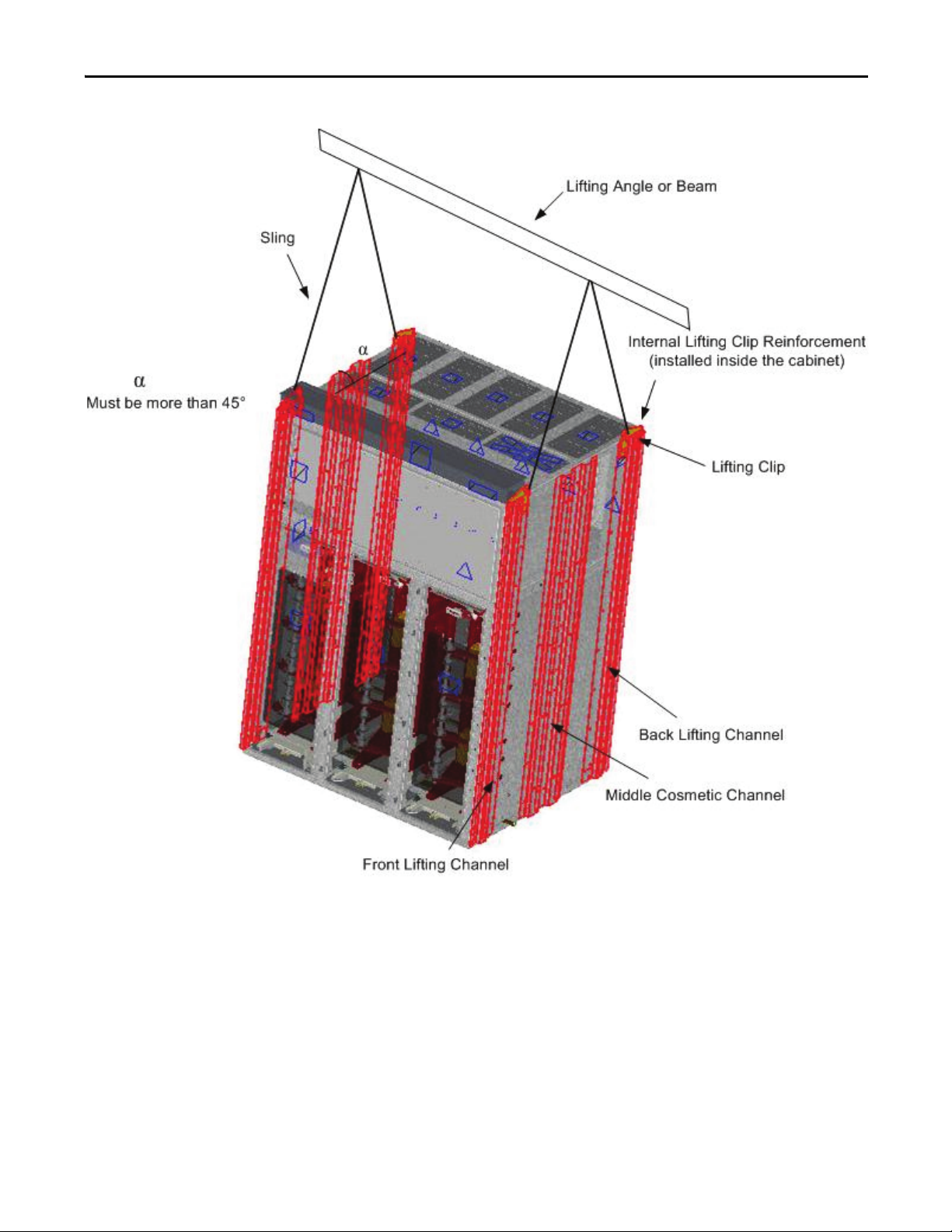
Figure 2 - Overhead Lifting of Converter Cabinet
Transportation and Handling Chapter 2
Rockwell Automation Publication 7760-IN001B-EN-P - June 2013 7
Page 10
Chapter 2 Transportation and Handling
2 x 6 in. minimum (50.8 x 152.4 mm)
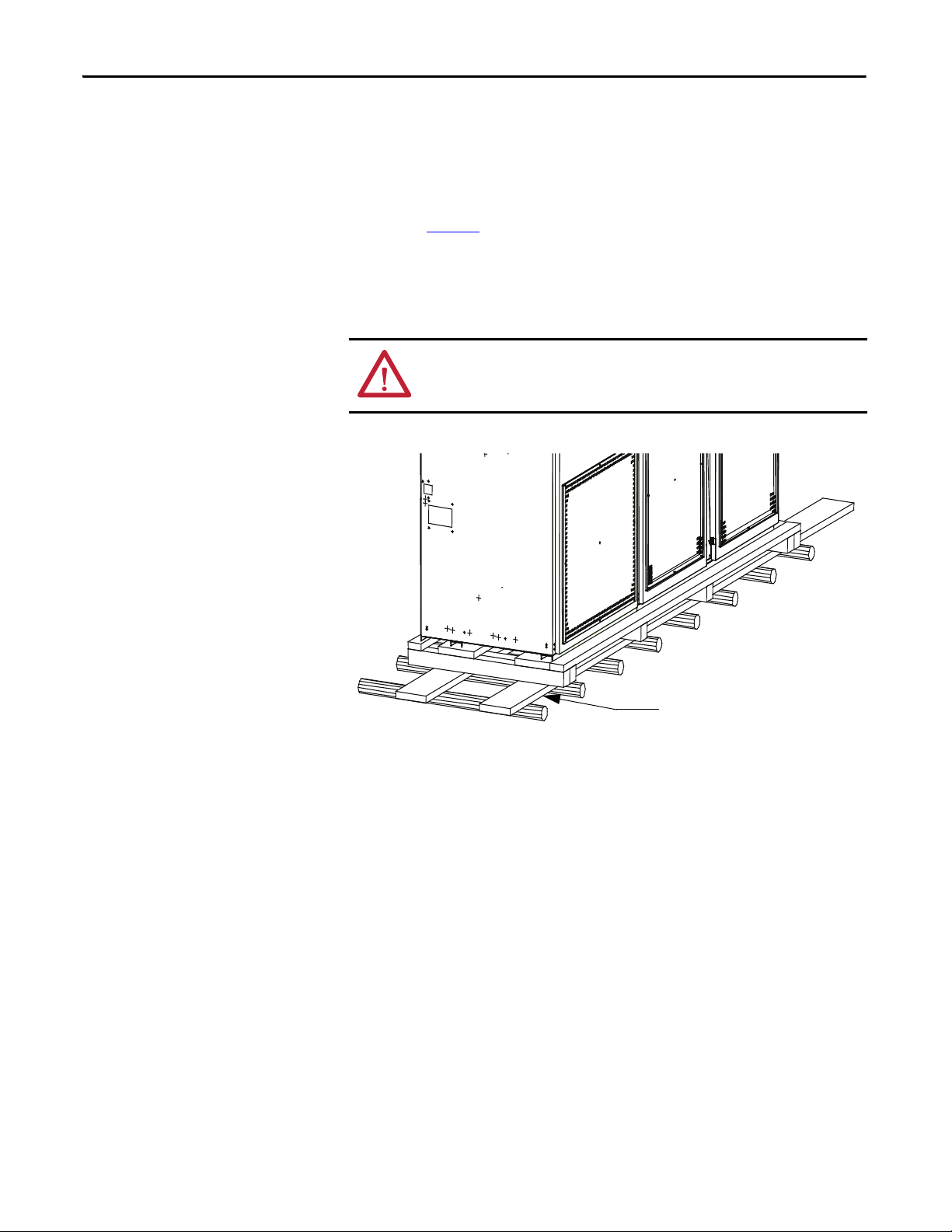
Rod or Pipe Rollers
This method is only suitable when there are no inclines and the controller is
being moved on level floor. Boards 50 x 152 mm (2 x 6”) or equivalent and at
least 300 mm longer than the controller must be placed under the shipping skid,
as shown in Figure 3
Carefully ease the shipping skid over the rollers until the equipment weight is
borne on the rollers. The controller can be rolled to its desired location. Steady
the load to prevent tipping.
Figure 3 - Rod or Pipe Rollers
.
ATT EN TI ON : Ensure that the load rating of all lifting equipment is sufficient to
safely raise the controller sections. Refer to the packing slip for shipping
weights.
Fork Lift Truck
A single fork lift truck may be used, extreme caution must be exercised.
1. Insert the forks into openings of the shipping skid from the rear of the
controller.
2. Carefully balance the controller on the forks and apply safety straps.
Shipping Skid Removal
Internal access is not required to remove the wooden shipping skid from the
converter cabinet. External angle brackets attached to the enclosure are used to
attach the enclosure to the wooden skid.
Remove the angle brackets and the associated hardware. When the enclosure is
lifted by overhead means, the wooden skid can be removed.
8 Rockwell Automation Publication 7760-IN001B-EN-P - June 2013
Page 11

Equipment Installation
Chapter 3
Removal of Overhead Lifting Brackets and Channels
Before joining to adjacent equipment, the lifting brackets and exterior vertical
lifting channels from the converter cabinet must be removed.
Removing of the lifting brackets requires access to the interior of the enclosure
where corresponding internal brackets are located and require removal. Please
refer to page 16
It will be necessary to remove the converter roll-out modules from the enclosure
to install power connections to the adjacent equipment and to install hardware to
secure the enclosure to its floor.
To remove converter modules from the cabinet, the following operations are
necessary:
1. Open the Medium Voltage Doors (see below)
2. Remove the Medium Voltage Front Cover (page 10
3. Disconnect Fiber Optic Cables (page 10
4. Disconnect Flexible Braided Links (page 12
5. Disconnect Current Loop Wire (page 12
6. Disconnect Mechanical Fastening of Converter Module (page 13
for hardware removal details.
)
)
)
)
)
Opening the Front Medium Voltage Doors of the Converter Cabinet
7. Installation of converter roll-out module ramp (page 14
8. Installation of Pull Handle (page 15
Access to the medium voltage converter section is attained by opening the three
lower doors. The left door is generally equipped with interlocking with upstream
equipment. The specifics of this interlocking depends on customer requirements
and is provided in the customer drawings.
Rotating the door handle unlatches the door allowing it to be opened. DO NOT
force open the doors.
The middle and right medium voltage doors are mechanically interlocked with
the left medium voltage door such that the left door must be opened before the
middle and right doors can be opened. Similarly, the left door cannot be closed
until both the middle and right doors are closed and latched.
Rockwell Automation Publication 7760-IN001B-EN-P - June 2013 9
)
)
Page 12
Chapter 3 Equipment Installation
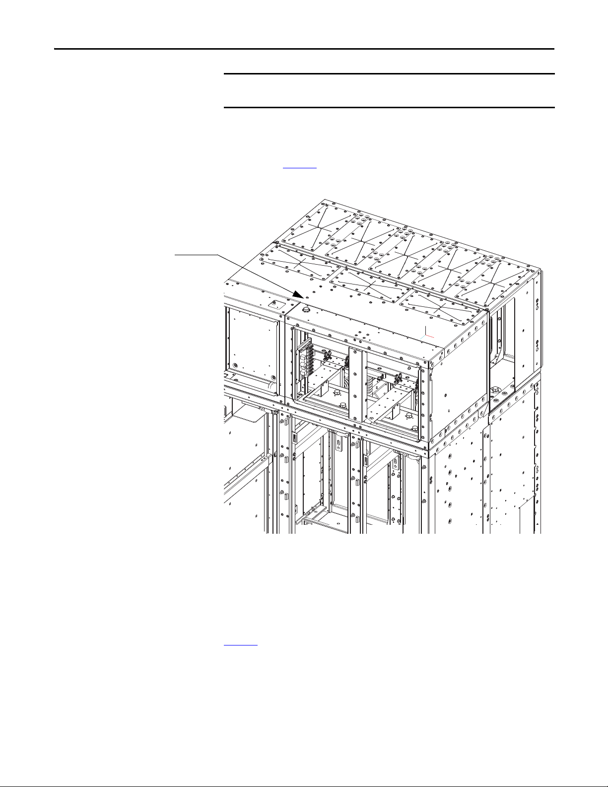
Medium Voltage
Front Cover
Remove Medium Voltage Front Cover
Access to the medium voltage area above the middle and right doors is attained
by removing the bolts that hold the cover in place (Figure 4
ATT EN TI ON : Ensure that power to the unit has been shut down and locked out
before accessing medium voltage areas. Failure to do so may result in severe
injury or death.
Figure 4 - Medium Voltage Front Cover Identification
).
Disconnect Fiber Optic Cables to Converter Roll-out Modules
ATT EN TI ON : Fiber optic cables can be damaged by bending the cables with a
radius of less than 50 mm (2 in.).
To disconnect the fiber optic cables on each of the converter modules, it is
necessary to remove the Front Medium Voltage front cover located over the
middle and right medium voltage doors. Removal of this panel provides access to
the multi-channel fiber optic circuit board.
10 Rockwell Automation Publication 7760-IN001B-EN-P - June 2013
Page 13
IMPORTANT
Multi-channel Fiber
Optic Board location
Equipment Installation Chapter 3
Note the locations of the fiber optics from the fiber optic circuit board before
disconnecting them.
The fiber optic cables are individually identified. Fiber optic cables are
disconnected from the circuit by squeezing the latch lever of each fiber optic
terminal and pulling the fiber optic line out of the multi-channel fiber optic
circuit board (Figure 5
Figure 5 - Multi-channel Fiber Optic Circuit Board Location
)
The cables should be carefully coiled on top of the PowerBricks, so they will not
be damaged when the cart is removed
Reconnection of fiber optic cables requires that the fiber optic cables, for each
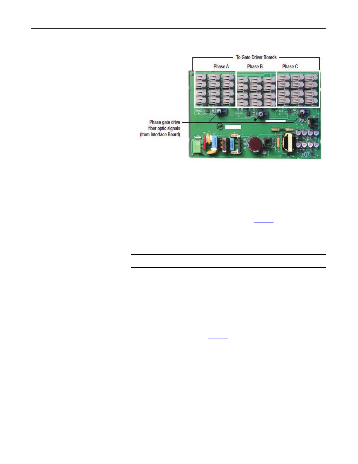
phase of converter module, must be connected to the transmitter terminals of the
appropriate phase location on the fiber optic multiplexer circuit board. Within
each phase of fiber optic connectors the order of connection is not critical.
Figure 6
shows a close-up view of the fiber optic multiplexer board and the
grouping of fiber optic connections per phase.
Rockwell Automation Publication 7760-IN001B-EN-P - June 2013 11
Page 14
Chapter 3 Equipment Installation
IMPORTANT
Figure 6 - Fiber Optic Multiplexer Board
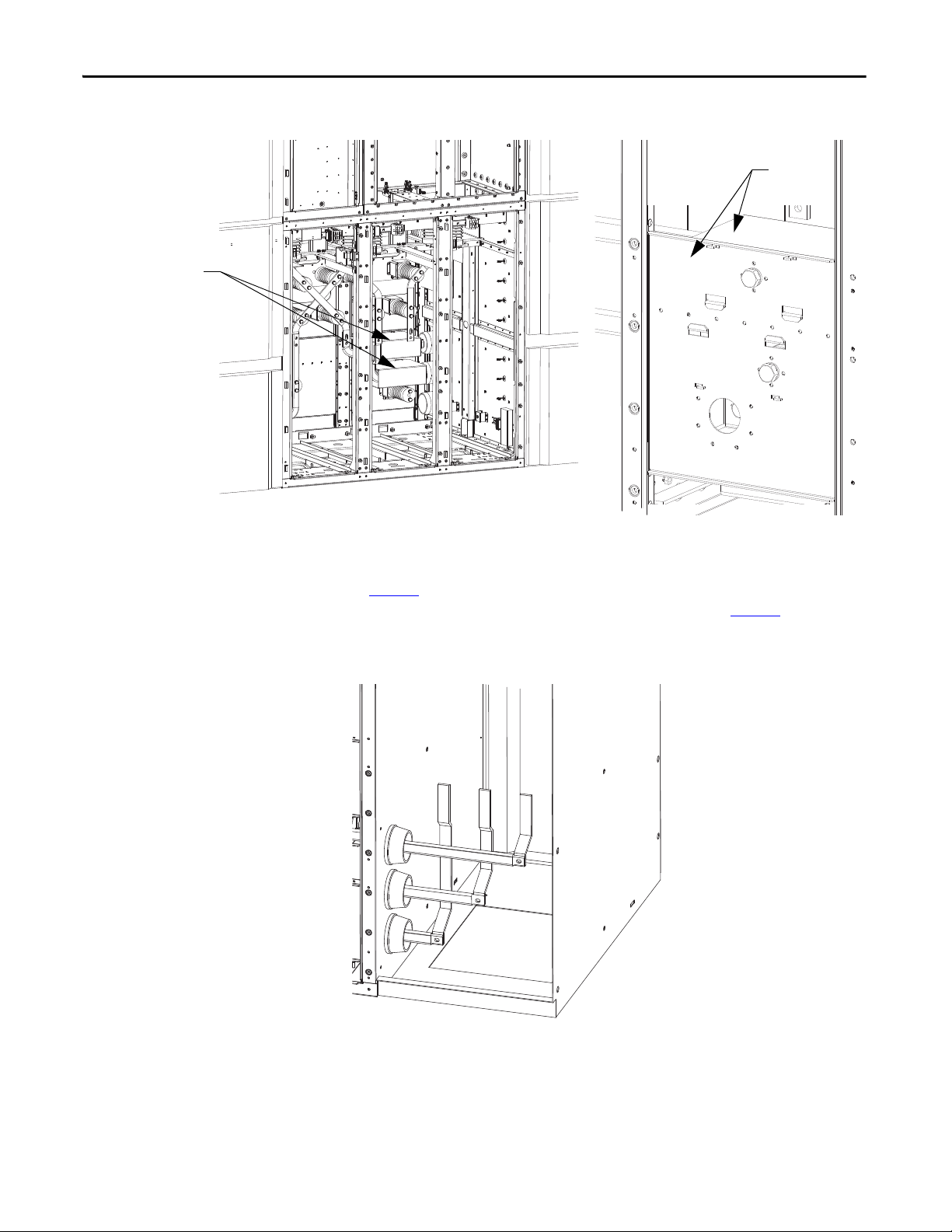
Disconnect Flexible Links
At the top of each roll-out converter module, two flexible links are provided to
connect power to the converter module. A 13 mm hex tool is needed to remove
the hardware at the upper end of the flexible link. The location of the top flexible
link connections to the converter bus are shown in Figure 7
The cable from the rear of the cart must be freed from the clamps that secure it to
the structure.
The cable must be re-attached to these clamps when the cart is re-installed.
.
Disconnect Current Loop Wires
Power for the gate driver circuit boards is provided by current transformers that
derive power from a low voltage loop of wire that is visible at the front of the rollout converter modules. The current loop wire terminations are accessible at the
front and can be disconnected at terminal blocks located above each of the
converter modules, as shown in Figure 7
.
12 Rockwell Automation Publication 7760-IN001B-EN-P - June 2013
Page 15

Equipment Installation Chapter 3
Terminal Block for Current Loop
Top Bo lt
Location for
Mechanical
Attachment of
Roll-out
Conver ter
Modules
Fastener
Location for
Flexible
Power
Connections
Fastener location for
anchoring roll-out Converter
Module Base to enclosure
Disconnect Mechanical Fastening of Converter Modules
The three roll-out converter modules are mechanically attached within the
cabinet by hardware at the top and bottom. A 13 mm hex tool is needed to
remove the two sets of hardware (Figure 7
At the front bottom of each module, on its sheet metal base, two bolts are used to
secure the module to the cabinet. Removal of the bolts (using 17 mm hex tool) is
required to extract the module from the cabinet, as shown in Figure 7
Figure 8
Figure 7 - Removal of Fasteners at Top of Converter Module
.
) at the top of the module.
and
Figure 8 - Removal of Fasteners at Bottom of Converter Module
Rockwell Automation Publication 7760-IN001B-EN-P - June 2013 13
Page 16

Chapter 3 Equipment Installation
IMPORTANT
IMPORTANT
Install Converter Roll-out Module Ramp
A metal ramp assembly is provided that is required for the safe removal and
installation of the converter roll-out modules. The ramp has tabs that locate into
slots of the cabinetry (Figure 9
Figure 9 - Insertion of Ramp for Roll-out Converter Module
).
A clear space of 1500 mm is required in front of the equipment to facilitate
removal of the converter modules is required.
This method of removing the roll-out converter modules is only valid if the
equipment is installed on a level floor. If the equipment is installed on an
elevated platform, alternate means are required. Consult factory for details.
14 Rockwell Automation Publication 7760-IN001B-EN-P - June 2013
Page 17

Equipment Installation Chapter 3
IMPORTANT
IMPORTANT
Pull Handle
Ramp
Install Converter Roll-out Module Pull Handle
Do not push or pull on the clear barrier to remove the converter module.
At the base of the converter roll-out module, an attachment point for the pull
handle is provided.
The pull handle connects to the module base with a pin (Figure 10
Each converter roll-out module should be extracted by pulling outwards. The
converter roll-out module should be maintained level and not be tilted at least
until the middle wheels reach the ramp attachment points to the cabinet, as
shown in (Figure 11
Figure 10 - Insertion of Pull Handle for Roll-out Converter Module
).
).
Check the fiber optic and current loop cables are not being snagged or pinched
when removing or installing the converter module.
Rockwell Automation Publication 7760-IN001B-EN-P - June 2013 15
Page 18

Chapter 3 Equipment Installation
IMPORTANT
External Lifting Lugs
Vertical Lifting Channels
Figure 11 - Converter Module being Extracted from Enclosure
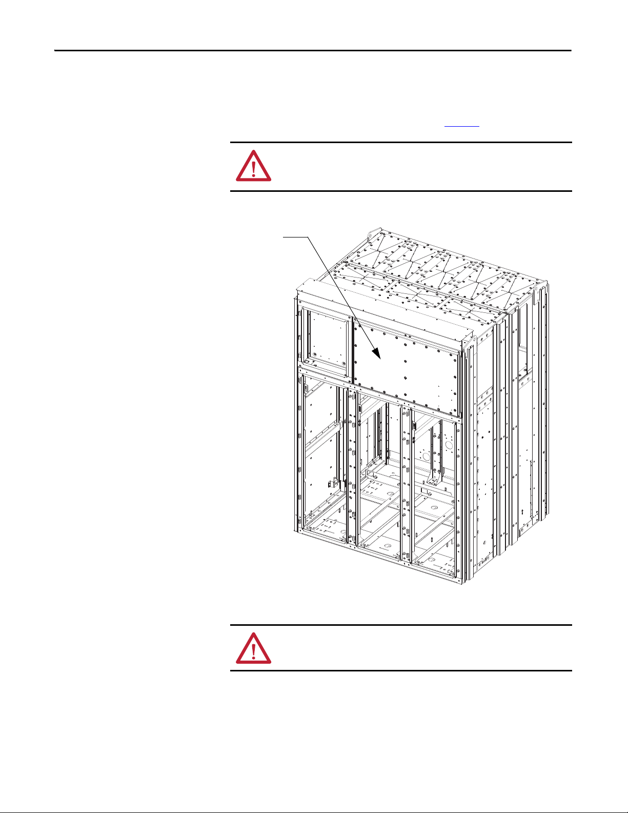
Removal of Lifting Provisions
Once it has been determined that overhead lifting of the controller is no longer
needed, the lifting components may be removed. There are 6 (six) vertical
channels, 4 (four) external lifting lugs (Figure 12
mounting brackets (Figure 13
). Rear access is required to remove the two internal
) and 4 (four) internal lug
lug mounting brackets at the rear of the structure. Care must be taken not to drop
the internal brackets into the cabinet while removing them.
The channels and external lifting lugs must be removed prior to mating to any
adjacent switchgear components.
Figure 12 - External Lifting Components
16 Rockwell Automation Publication 7760-IN001B-EN-P - June 2013
Page 19

Figure 13 - Internal Lifting Components
Internal Lifting Lug
Mounting Brackets
located in top four
corners
Equipment Installation Chapter 3
Install the Converter Cabinet
With Back Access
The installation method described below is valid for (the preferred) situations
when back access to the equipment is available.
Prior to moving one cabinet next to the other, the Horizontal Power Bus and
Bushings need to be inserted into the converter cabinet. Bushings will be fastened
to the adjacent switchgear cabinets at a later step.
At each end of the Bus Module, place a Bushing inside the enclosure with the fl at
surfaces facing out. Slide the bus through the bushing’s openings and the slots in
the supporting brackets until it is through the opposite side. For 1250 A rating
(single bus per phase) bus placement is in the lower of the two slots for each
phase, as shown in Figure 14
. Both slots will be used for 2000 A rating.
Rockwell Automation Publication 7760-IN001B-EN-P - June 2013 17
Page 20

Chapter 3 Equipment Installation
Lower slots for
1250A bus rating
Power Bus Bushing
Flat side facing o ut
Power Bus Bushing
Flat Side facing out
Adjacent switchgear cabinet
Power bus flush
with sidesheet
Figure 14 - Horizontal Power Bus and Bushing Placement
Depending on which side the converter cabinet will fit up to, the bus should be
flush with the side plate facing the mating side of the adjacent switchgear cabinet.
Figure 15 - Horizontal Power Bus Placement
18 Rockwell Automation Publication 7760-IN001B-EN-P - June 2013
Page 21

Equipment Installation Chapter 3
Rear Junction
Point
Front Flange Faces
Front Junction Points
(inside cabinet)
Without Back Access
If no back access to the equipment is available, the Horizontal Power Bus
Bushings must be installed and fastened on the respective switchgear cabinets
prior to connecting with the converter cabinet. The switchgear cabinets must be
first installed with the front, flush with the converter cabinet, then transversally
slid into place such that the bushings clear the associated openings in the
Converter Cabinet Main Bus Module.
Inter-Cabinet Connections
This section describes the electrical and mechanical connections between the
converter and the adjacent switchgear cabinets. For details regarding interconnections between two switchgear cabinets (e.g. Incoming Line Unit and
Bypass Unit), refer to the respective manufacturer’s instruction manuals.
Once the converter and adjacent switchgear cabinets are positioned next to each
other, ensure that both front flanges are flush (Figure 16
Figure 16 - SMC and Switchgear Cabinet Alignment
).
Rockwell Automation Publication 7760-IN001B-EN-P - June 2013 19
Page 22

Rear Junction
Point s (x5)
Front Junction
Point s inside
LV Panel (x2)
Front
Junction
Points inside
MV section
(x4)
Chapter 3 Equipment Installation
Locate the cabinetry junction points in the converter cabinet which connect the
converter cabinet with the adjoining switchgear equipment (M10 nuts). Fasten
with M10 hardware at these locations (6 along front, 5 along rear), as shown in
Figure 17
. Repeat operation for joining both switchgear cabinets to the converter
cabinet.
Figure 17 - Junction Point Locations
20 Rockwell Automation Publication 7760-IN001B-EN-P - June 2013
Page 23

Equipment Installation Chapter 3
SMC Floor
Anchoring
Adjacent Switchgear Cabinets
IMPORTANT
Floor Anchoring
The general location of the converter cabinet floor anchoring points is shown in
Figure 18
Refer to project specific dimension drawing for exact dimensions and anchoring
bolt mounting locations for all cabinets. Anchor holes accommodate 12 mm
(0.50”) hardware.
Figure 18 - Floor Anchoring
.
Installation of Power Bus Bushings
This step is only necessary if the installation procedure outlined in With Back
Access on page 17, (i.e. if the horizontal power bus bushings have been
inserted onto the horizontal power bus and currently reside loose on the bus
inside the converter cabinet’s main bus box.)
Move bushing against the side sheet of the adjacent switchgear cabinet, as
illustrated in Figure 19
and fasten using the supplied M8 hardware. This is typical for both sides.
Rockwell Automation Publication 7760-IN001B-EN-P - June 2013 21
. Align holes in bushing with holes in switchgear cabinet
Page 24

Chapter 3 Equipment Installation
Power Bus Bushing
Figure 19 - Installation of Power Bus Bushing
Install Power Bus Bushing Inserts
Partially slide bus through bushing and into the switchgear cabinet. Slide the
supplied bus bushing inserts onto bus as shown in Figure 20
supplied for the connections between the horizontal bus and the switchgear
risers, slide the bus boots caps next to the bushing inserts (refer to manufacturer
documentation for details).
Slide horizontal bus into the switchgear cabinet past the switchgear risers and
close to the side wall opposite the converter section.
Following the steps outlined above, insert the Power Bus bushing inserts and bus
boot caps (if applicable) onto the horizontal bus inside the switch-gear cabinet on
the opposite side of the converter cabinet.
. If bus boots were
22 Rockwell Automation Publication 7760-IN001B-EN-P - June 2013
Page 25

Equipment Installation Chapter 3
Switchgear Risers
Power Bus Bushing
Inserts
Once these operations are complete for both switchgear cabinets adjacent to the
converter cabinet, the equipment is ready for connecting the Power Bus to the
switchgear vertical risers.
Figure 20 - Installation of Power Bus Bushing Inserts (cutaway view)
Connect Power Bus to Switchgear Risers
Refer to the switchgear equipment documentation for detailed procedures on
connecting the Power Bus to the vertical risers and on installing the Insulating
Boots. Use the supplied M12 hardware and torque the connections (Figure 21
to the values indicated in the switchgear manufacturer’s documentation. This
needs to be completed for both switchgear cabinets adjacent to the converter
cabinet (e.g. Bypass unit, Main unit), as well as for switchgear units adjacent to
each other (e.g. Incoming Line Unit, Bypass Unit).
Once each phase of the Power Bus is bolted and torqued, slide bus inserts towards
the bushings from the switchgear cabinets until they are seated inside the bushing
tabs.
)
Rockwell Automation Publication 7760-IN001B-EN-P - June 2013 23
Page 26

Chapter 3 Equipment Installation
Bolted Connections
between Power Bus
and vertical bus risers
Bus links
Bus bushings
Figure 21 - Installation of Power Bus (cutaway view)
Install Lower Bus Links in the Converter Cabinet
The Converter Bus Bushings are to be installed in the lower rear section of the
Power Converter section.
Figure 22 - Installation of Lower Bus Links, Line Side
24 Rockwell Automation Publication 7760-IN001B-EN-P - June 2013
Page 27

Equipment Installation Chapter 3
IMPORTANT
On the left side (line side) of the converter cabinet, install (3) bus links as
indicated in Figure 22
.
Fasten the bus links to the Converter Bus using the supplied M12 hardware.
Fasten the bus links to the back insulators using the supplied M10 hardware.
Torque all connections to the values indicated on page 37
. DO NOT OVER
TIGHTEN.
On the right side (load side) of the converter cabinet (Figure 23
and middle bus links first. DO NOT install lower link yet.
Figure 23 - Installation of Lower Bus Link, Load Side
), install the top
Fasten the bus links to the Converter Bus using the supplied M12 hardware.
Fasten the bus links to the back insulators using the supplied M10 hardware.
Torque all connections to the values indicated on page 37
.
Two clear barriers are supplied to cover the top two bus links. Install the clear
barrier over each bus link (Figure). The longer barrier is mounted over the
upper bus link. Once installed, the bottom bus link may be installed.
Rockwell Automation Publication 7760-IN001B-EN-P - June 2013 25
Page 28
Chapter 3 Equipment Installation
Rear view of
barrier tabs
Barriers
Figure 24 - Installation of Lower Bus Link Barriers
Within the switchgear cabinet, the lower bus links are to be fastened to the bus
stabs using the hardware supplied on these connections, using the torque values
on page 37
the cap screws to fasten barriers in this area, as described on page 27
. These special cap screws have an internal thread within the head of
. Install the
supplied white barriers using the nylon screws provided.
Figure 25 - Installation of Lower Bus Links within Switchgear Cabinet (rear view)
26 Rockwell Automation Publication 7760-IN001B-EN-P - June 2013
Page 29

Equipment Installation Chapter 3
Nylon Screw
mounting location
Barrier 1
Barrier 2
Installation of Barriers
One (1) clear barrier is provided for installation over the top of the bus
connections, as shown in Figure 26
. Install the barrier onto the rear side of the
bus links within the switchgear cabinet, using the metric nylon screws supplied.
Note the orientation of the barriers as shown below. Installation is typical for
both sides depending on controller configuration.
Figure 26 - Installation of switchgear barrier (rear view)
Two clear barriers (Figure 27) are provided for installation inside the converter
cabinet.
Figure 27 - Clear barriers for installation inside SMC cabinet
Install barriers in the lower rear section of converter cabinet, noting the
orientation shown in Figure 28
. Use the existing hardware from bottom cover
plates.
Rockwell Automation Publication 7760-IN001B-EN-P - June 2013 27
Page 30

Chapter 3 Equipment Installation
Mounting Provision
Barrier 2
Barrier 1
Ground Bus Link
Ground Bus Link
Figure 28 - Installation of SMC Barriers (cutaway view)
Ground Bus Linking
Connect the supplied links from the converter cabinet ground bus to the
switchgear cabinet ground bus, as shown in Figure 29
hardware using values on page 37
Figure 29 - Installation of Ground Bus Link (cutaway view)
.
(typical both sides). Fasten
28 Rockwell Automation Publication 7760-IN001B-EN-P - June 2013
Page 31

Equipment Installation Chapter 3
IMPORTANT
TIP
TIP
Electromechanical Interlock
The Bulletin 776X interlocking system is comprised of both an electrical and a
mechanical system. The unit has been shipped with the interlocking system
disabled for ease of transportation, inspection and installation.
The medium voltage access doors, on the front of the converter cabinet are
equipped with a Guardmaster electromechanical interlock. Once door latch is
installed, control power and inter-cabinet control wire must be completed.
These doors will not open once the door latch is installed unless control power
is applied and wiring is complete.
WARNING: Failure to install the interlock latch and completion of the
electromechanical interlocking system, may lead to personal injury or death,
property damage, or economic loss.
The door latch of the Guardmaster electromechanical lock is not installed on the
door flange when the unit is shipped from the factory. The door latch is shipped
loose, inside a bag attached to the inside of the leftmost MV door (Figure 30
Ensure the following steps have been completed before installing the door latch
on the door flange.
1. Complete the mechanical installation of the equipment into final position.
).
2. Complete low voltage wiring between functional units and ensure control
circuit is functioning properly.
3. Ensure control power is connected to the controller.
The electromechanical interlock is a fail safe device. Once the door latch is
installed and the door is closed, it will remain locked in the closed position
until all control wiring is complete and to permit energization of the low
voltage controls within the converter cabinet.
Once steps 1 through 3 noted above are completed, the door latch may be
installed and interlock integrity tested.
To install the Guardmaster door latch, attach it to the bracket already attached to
the rear of the leftmost medium voltage door, using only the supplied hardware
(Figure 31
interlock is operating properly before putting controller into service. Refer to
project specific electrical diagrams for control power connections and
operational details.
). Interlock is setup and adjusted at factory before shipment. Ensure
The mechanical interlocking system prevents the mechanical latching of the
left most medium voltage door unless the middle and right medium voltage
doors are closed and latched.
Rockwell Automation Publication 7760-IN001B-EN-P - June 2013 29
Page 32

Chapter 3 Equipment Installation
Figure 30 - Location of Guardmaster Door Latch shipped loose
Figure 31 - Guardmaster door latch, screws and tool bit
Figure 32 - Guardmaster door latch installed
30 Rockwell Automation Publication 7760-IN001B-EN-P - June 2013
Page 33

OneGear Standard Plenum
Chapter 4
Assemble Standard Plenum to Cabinetry
1. Use drawing 81020-780 as a general guideline for fixing the panels. This
assembly drawing should be supplied with the order.
2. Identify the right materials necessary for this operation (see following
figures).
• Inner connecting brackets to switchgear, qty.3 (81020-999-54/56,
81023-001-54).
• Outer connecting brackets to switchgear, qty.5 (81023-07501/02/03).
• Plenum front and back assembly, qty.3 (81020-990-52).
• One Gear inner connecting brackets, qty.6 (81023-001-53,
81020999-53/55).
• One Gear outer connecting brackets, qty.10 (81020-991-04/05/06).
• If a 7760 or 7761 is ordered there will be an extension and end
components included (81021-282-52, 81021-637-02, and 81020-998).
• Hardware (M8 HHCS - 29107-304-04, Flat washer 19 mm (0.75”)
OD, Flat washer 28 mm (1.125”) OD, Lock washer, M6 self-tapping
screws 29171-640-01 for extension).
• 25 mm (1”) Gasket and silicone tube
Figure 33 - Components for Plenum Assembly
3. Install the switchgear gas duct per manufacturer’s instructions (e.g. ABB
UniGear type ZS1 – Standard Gas Duct Assembling Procedure).
Rockwell Automation Publication 7760-IN001B-EN-P - June 2013 31
Page 34

Chapter 4 OneGear Standard Plenum
4. Locate the rear inner connecting bracket for connecting to the switch-gear
(81020-999-56) and temporarily fasten in place using M8 hardware
(Figure 34
Figure 34 - Attaching from and rear, inner bracket
).
5. Fasten the front inner connecting bracket for connection to the switchgear
(81020-999-54) temporarily using M8 hardware.
6. Apply gasket to the bottom flange of all front and rear assemblies
(Figure 35
Figure 35 - Gasket location
).
7. Locate the mounting holes on top of the OneGear unit to mount the front
and rear assembly (Figure 36
32 Rockwell Automation Publication 7760-IN001B-EN-P - June 2013
).
Page 35

Figure 36 - Mounting location for front and rear assembly
OneGear Standard Plenum Chapter 4
8. Take the front and rear assembly, position it as shown in Figure 37 and use
the M8 hardware (M8 HHCS, 28 mm (1.125”) OD flat washers and lock
washers) to fasten it.
Figure 37 - Front and rear assembly mounted on top of cabinet
9. Attach the outer side bracket (81023-075-02) at the rear and front using
the M8 hardware (M8 HHCS, 19 mm (0.75”) OD flat washers and lock
washers). Refer to Figure 38
Rockwell Automation Publication 7760-IN001B-EN-P - June 2013 33
.
Page 36

Chapter 4 OneGear Standard Plenum
Figure 38 - Front and rear outer side bracket attached
10. Remove the temporarily fastened hardware from Step 4 and 5; the inner
side bracket should stay in place as a result of Step 9.
11. Attach the outer side bracket that is on an angle (81023-075-01) at the
front and rear of the plenum using M8 hardware (M8 HHCS, 19 mm
(0.75”) OD flat washers and lock washers). Refer to Figure 39
.
Figure 39 - Attach outer side bracket at front and rear
12. Install the inner top bracket (81023-001-54) and outer top bracket
(81023-075-03) using M8 hardware (M8 HHCS, 19 mm (0.75”) OD flat
washers and lock washers), refer to Figure 40
.
34 Rockwell Automation Publication 7760-IN001B-EN-P - June 2013
Page 37

OneGear Standard Plenum Chapter 4
Figure 40 - Attaching outer and inner top brackets
At this point, the OneGear SMC plenum should be completely attached to the
switchgear equipment. Apply silicone to gaps or holes located at bends and
corners. Continue with installation of the OneGear plenum components.
13. Temporarily attach the inner rear and front bracket (81020-999-56/53)
similar to step 4.
14. Take the front and rear assembly, position it as shown in figure 6 and use
the M8 hardware (M8 HHCS, 28 mm (1.125”) OD fl at washers and lock
washers) to fasten it.
15. Attach the outer side bracket (81020-991-05) similar to Step 9.
16. Remove the temporarily fastened hardware in Step 13 and attach the outer
side bracket at the front and rear that is on an angle (81020-991-04) as in
Step 11.
17. Install the inner top bracket (81023-001-53) and outer top bracket
(81020-991-06) using M8 Hardware (M8 HHCS, 19 mm (0.75” OD) flat
washers and lock washers), as in Step 12.
Two sections of the OneGear plenum should now be fully installed (Figure 41
Apply silicone to gaps or holes located at bends and corners. Repeat steps 13-17
to complete the assembly of the OneGear plenum. Review the assembly and
silicone any remaining gaps or holes in the connection.
).
Rockwell Automation Publication 7760-IN001B-EN-P - June 2013 35
Page 38

Chapter 4 OneGear Standard Plenum
IMPORTANT
Figure 41 - Two sections of the OneGear Plenum installed
18. If a Bulletin 7761 product is ordered, an end plate (81020-998) and
extension with screen will be required (81021-282-52, 81021-637-02).
Install the end plate with M8 hardware.
If an end plate is ordered with no exit hole, it must be installed first or it will be
very difficult to attach to the top plate, see Figure 42
Figure 42 - OneGear Unit on the end (7761)
.
19. Attached the extension to the end plate using M6 self-tapping screws.
Subsequent extensions are attached using M8 hardware.
For Bulletin 7760, 7762 and 7763 equipment, switchgear is provided on both
sides of the SMC. Therefore, steps 4-12 will need to be repeated using the
switchgear front and rear assembly.
36 Rockwell Automation Publication 7760-IN001B-EN-P - June 2013
Page 39

General Reference
Appendix A
Torque Requirements
The following table contains the recommended torquing values for hardware
required to fasten electrical connections (bus-bus or bus-flexible bus links).
Hardware Recommended Torque
N•m ft•lb
M6 6.0 4.4
M8 14.0 11.0
M10 29.0 21.0
M12 50.0 37.0
M16 124.0 91.0
Rockwell Automation Publication 7760-IN001B-EN-P - June 2013 37
Page 40

Appendix A General Reference
Notes:
38 Rockwell Automation Publication 7760-IN001B-EN-P - June 2013
Page 41

Notes:
General Reference Appendix A
Rockwell Automation Publication 7760-IN001B-EN-P - June 2013 39
Page 42

Appendix A General Reference
Notes:
40 Rockwell Automation Publication 7760-IN001B-EN-P - June 2013
Page 43

Page 44

Rockwell Automation Support
Rockwell Automation provides technical information on the Web to assist you in using its products.
At http://www.rockwellautomation.com/support
code and links to software service packs, and a MySupport feature that you can customize to make the best use of these
tools. You can also visit our Knowledgebase at http://www.rockwellautomation.com/knowledgebase
information, support chat and forums, software updates, and to sign up for product notification updates.
, you can find technical manuals, technical and application notes, sample
for FAQs, technical
For an additional level of technical phone support for installation, configuration, and troubleshooting, we offer
SM
Te c h C o n n e c t
representative, or visit http://www.rockwellautomation.com/support/
support programs. For more information, contact your local distributor or Rockwell Automation
.
Installation Assistance
If you experience a problem within the first 24 hours of installation, review the information that is contained in this
manual. You can contact Customer Support for initial help in getting your product up and running.
United States or Canada 1.440.646.3434
Outside United States or Canada Use the Wor ldwi de Lo cato r at http://www.rockwellautomation.com/rockwellautomation/support/overview.page, or contact your local
Rockwell Automation representative.
New Product Satisfaction Return
Rockwell Automation tests all of its products to help ensure that they are fully operational when shipped from the
manufacturing facility. However, if your product is not functioning and needs to be returned, follow these procedures.
United States Contact your distributor. You must provide a Customer Support case number (call the phone number above to obtain one) to your
Outside United States Please contact your local Rockwell Automation representative for the return procedure.
distributor to complete the return process.
Documentation Feedback
Your comments will help us serve your documentation needs better. If you have any suggestions on how to improve this
document, complete this form, publication RA-DU002
Medium Voltage Products, 135 Dundas Street, Cambridge, ON, N1R 5X1 Canada, Tel: (1) 519.740.4100, Fax: (1) 519.623.8930
Online: www.ab.com/mvb
Allen-Bradley, Rockwell Software, Rockwell Automation, and TechConnect are trademarks of Rockwell Automation, Inc.
Trademarks not belonging to Rockwell Automation are property of their respec tive companies.
Publication 7760-IN001B-EN-P - June 2013
Supercedes Publication 7760-IN001A-EN-P - January 2013 Copyright © 2013 Rockwell Automation, Inc . All rights reserved. Printed in Canada.
, available at http://www.rockwellautomation.com/literature/.
 Loading...