

Page 1

OneGear™ Motor Control Center
Full-voltage Non Reversing Starter (7.2 kV)
Bulletin 7712
Installation Instructions
Page 2
Important User Information
IMPORTANT
Read this document and the documents listed in the Additional Resources section about installation, configuration, and
operation of this equipment before you install, configure, operate, or maintain this product. Users are required to
familiarize themselves with installation and wiring instructions in addition to requirements of all applicable codes, laws,
and standards.
Activities including installation, adjustments, putting into service, use, assembly, disassembly, and maintenance are required
to be carried out by suitably trained personnel in accordance with applicable code of practice.
If this equipment is used in a manner not specified by the manufacturer, the protection provided by the equipment may be
impaired.
In no event will Rockwell Automation, Inc. be responsible or liable for indirect or consequential damages resulting from the
use or application of this equipment.
The examples and diagrams in this manual are included solely for illustrative purposes. Because of the many variables and
requirements associated with any particular installation, Rockwell Automation, Inc. cannot assume responsibility or
liability for actual use based on the examples and diagrams.
No patent liability is assumed by Rockwell Automation, Inc. with respect to use of information, circuits, equipment, or
software described in this manual.
Reproduction of the contents of this manual, in whole or in part, without written permission of Rockwell Automation,
Inc., is prohibited.
Throughout this manual, when necessary, we use notes to make you aware of safety considerations.
WARNING: Identifies information about practices or circumstances that can cause an explosion in a hazardous environment,
which may lead to personal injury or death, property damage, or economic loss.
ATTENTION: Identifies information about practices or circumstances that can lead to personal injury or death, property
damage, or economic loss. Attentions help you identify a hazard, avoid a hazard, and recognize the consequence.
Identifies information that is critical for successful application and understanding of the product.
Labels may also be on or inside the equipment to provide specific precautions.
SHOCK HAZARD: Labels may be on or inside the equipment, for example, a drive or motor, to alert people that dangerous
voltage may be present.
BURN HAZARD: Labels may be on or inside the equipment, for example, a drive or motor, to alert people that surfaces may
reach dangerous temperatures.
ARC FLASH HAZARD: Labels may be on or inside the equipment, for example, a motor control center, to alert people to
potential Arc Flash. Arc Flash will cause severe injury or death. Wear proper Personal Protective Equipment (PPE). Follow ALL
Regulatory requirements for safe work practices and for Personal Protective Equipment (PPE).
Allen-Bradley, Rockwell Software, Rockwell Automation, and TechConnect are trademarks of Rockwell Automation, Inc.
Trademarks not belonging to Rockwell Automation are property of their respective companies.
Page 3

Chapter 1
Equipment Overview Overview ................................................................................. 1-1
Table of Contents
Chapter 2
Chapter 3 Overview ................................................................................ 3-1
Cabinet Handling Instructions ................................................ 3-2
Overhead Lifting Method ................................................. 3-2
Rod and Pipe Rollers ........................................................ 3-3
Fork Lift Truck ................................................................. 3-4
Shipping Skid Removal .................................................... 3-4
Overview .................................................................................. 2-1
Unpacking and
Inspecting
Transportation
and Handling
Chapter 4 Equipment Installation 4.1 Removal of Overhead Lifting Brackets .................... 4-1
4.2 Open MV Door .......................................................... 4-2
4.3 Removal of the Contactor Cart .................................. 4-3
4.4 Remove Inter Compartment Barrier .......................... 4-7
4.5 Remove Bottom Conduit Cover ................................ 4-9
4.6 Final Product Placement and Joining of Adjacent Units . 4-9
4.6.1 Mechanical Connections between Enclosures . 4-11
4.6.1.1 Joining Incoming Breaker to Starter ........... 4-15
4.6.1.2 Joining Incoming Section to Starter ........... 4-16
4.6.1.3 Joining Section to Section .......................... 4-17
4.7 Floor Anchoring ...................................................... 4-18
4.8 Connecting to Load Terminals ................................ 4-19
4.9 Ground Bus Linking ................................................ 4-20
4.10 Main Bus Linking .................................................... 4-21
4.11 Placing the Contactor Back Into the Starter ............. 4-25
Chapter 5 Procedure ................................................................................ 5-1
Standard Plenum
Assembly Procedure
Appendix A Torque Values Torque Values for Hardware .................................................. A-1
7712-IN001B-EN-P – June 2013
Page 4

ii Table of Contents
7712-IN001B-EN-P – June 2013
Page 5
Chapter 1
Equipment Overview
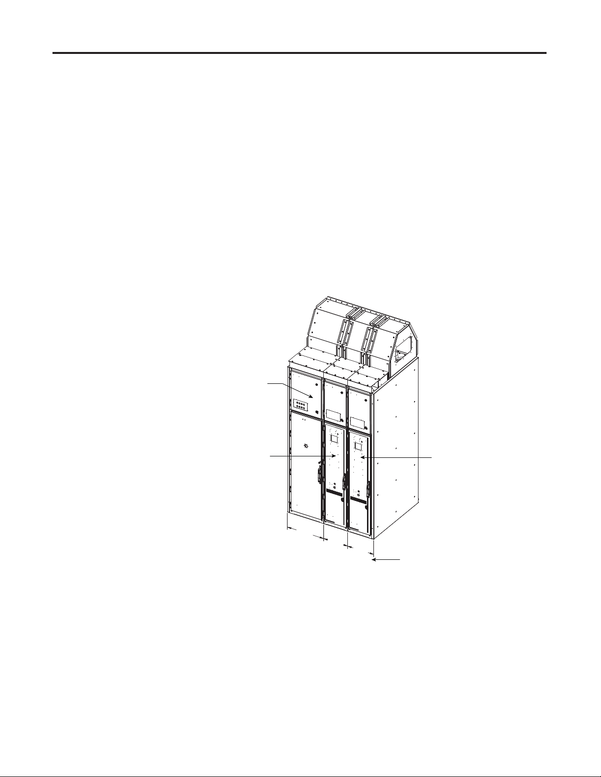
Overview The OneGear™ Bulletin 7712 controller is a one-high full voltage non-
reversing starter. The starter comes with the following standard items:
• Drawout Vacuum Contactor
• Main Power Rated Fuses
• Low Voltage Control Panel with low voltage controls
Figure 1.1 shows an overview of a typical Motor Control Center complete
with two Bulletin 7712 units and a Bulletin 7791 incoming line unit.
Refer to project documentation for specifi c confi guration details and
dimensions.
Incoming Cabinet
(Bulletin 7791)
Starter Cabinet
(Bulletin 7712)
531,5
[20.92]
350,0
[13.78]
381,5
[15.02]
Note:
This dimension includes the end side sheet of metal.
Starter Cabinet
(Bulletin 7712)
Figure 1.1 – Typical Bulletin 7712 OneGear™ One-High Starter
All cabinets are shipped individually or as part of a shipping split. This
document describes the handling and installation of the starter and with
Incoming Breaker, Incoming Section and Joining Section-to-Sections.
Installation and connection instructions for switchgear cabinets, that are
adjacent to each other is covered by the respective manufacturer’s
documentation and is not included in the scope of this document.
7712-IN001B-EN-P – June 2013
Page 6

1-2 Equipment Overview
7712-IN001B-EN-P – June 2013
Page 7

Chapter 2
Unpacking and Inspecting
Overview Before leaving the factory, the controller has been tested mechanically and
electrically.
Immediately upon receiving the controller, remove the packing and check
for possible shipping damage. Report any damage immediately to the
claims offi ce of the carrier.
After unpacking, check the items received against the Bill of Lading to
ensure that the nameplate description of each item agrees with the material
ordered. Inspect the controller for physical damage as stated in the Rockwell
Automation Conditions of Sale.
All claims for breakage and damage, whether concealed
Remove all packing material, wedges or braces from within the controller.
I M P O R T A N TI M P O R T A N T
or obvious, must be made to the carrier by the customer
as soon as possible after receipt of the shipment. Rockwell
Automation will render reasonable assistance in the
securing of adjustment for such damage claims.
If any part of the equipment will not be installed when it is unpacked, it
should be stored in a clean dry place. The storage temperature must be between -20 °C (-4 °F) and 75 °C (167 °F) with a maximum humidity of 95%
non-condensing.
7712-IN001B-EN-P – June 2013
Page 8

2-2 Unpacking and Inspecting
7712-IN001B-EN-P – June 2013
Page 9
Chapter 3
Transportation and Handling
Overview The controller sections are shipped on wooden skids bolted to the cabinetry.
Lifting angles are installed at the top of the cabinetry . The controller sections
must be maintained in the upright position during any handling.
Ensure that the load rating of all lifting equipment is
suffi cient to safely raise the controller sections. Refer to
the packing slip for shipping weights.
Round rollers can be used to assist in moving the equipment to the installation
site. Once at the fi nal site, rollers can be used to place the sections in their
desired position.
Care must be exercised when using either a forklift or the
pipe rolling technique for positioning purposes to ensure
that the equipment is not scratched, dented or damaged
in any manner. Always exercise care to stabilize the
controller during handling to guard against tipping and
injury to personnel.
It cannot be stressed how important it is that the customer
I M P O R T A N TI M P O R T A N T
installation duties are performed correctly. Any errors
will likely cause delays in commissioning or damage to
the equipment.
7712-IN001B-EN-P – June 2013
Page 10
3-2 Transportation and Handling
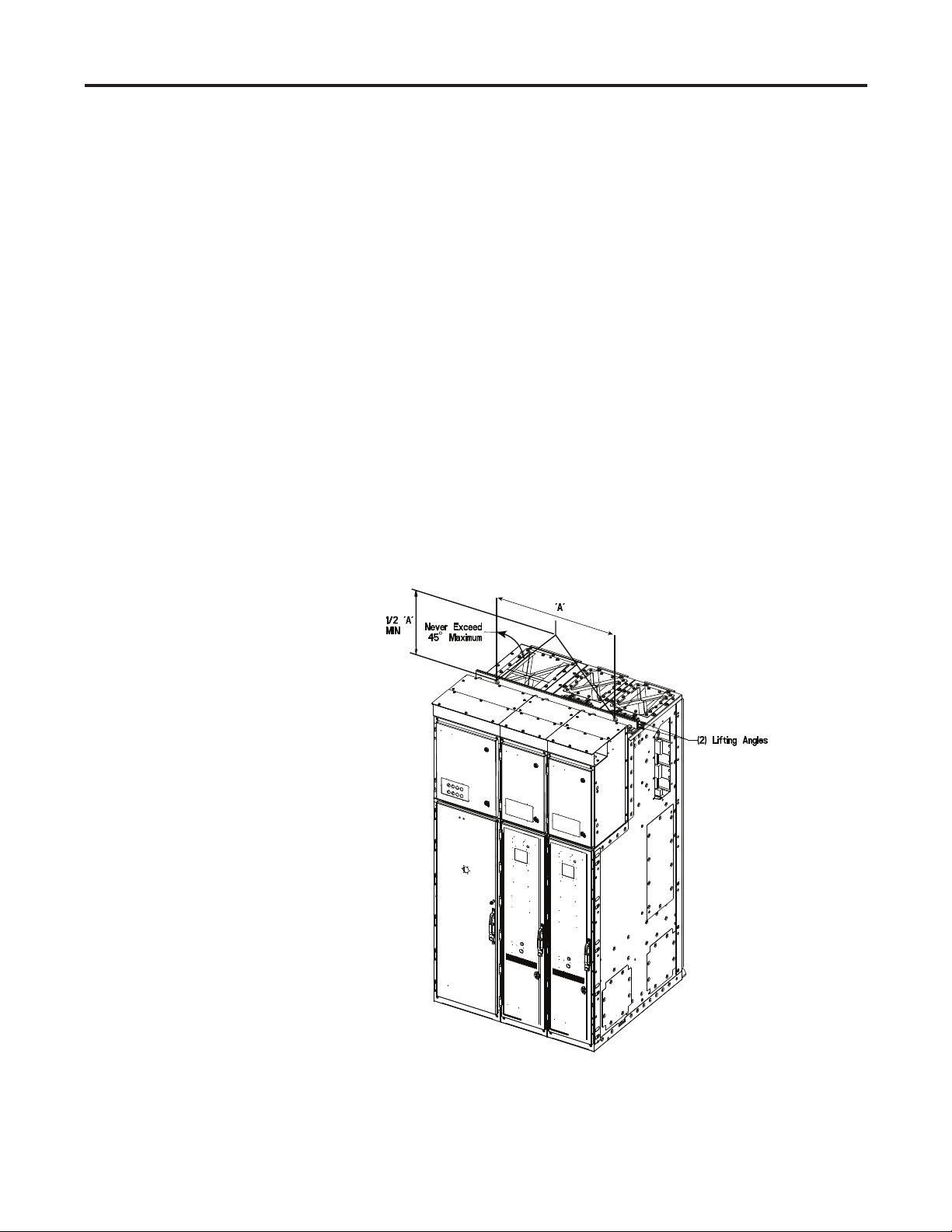
Cabinet Handling Instructions When lifting the Bulletin 7712 OneGear™ cabinet, the lifting instructions
specifi ed below must be followed.
Overhead Lifting Method
1. Verify that the front/back lifting channels and the middle cosmetic
channels are all installed and that the connecting hardware is tightened
to the cabinet.
2. Verify that the four (4) lifting clips have corresponding internal lifting
clips installed and connected. Lifting clip holes are 30 mm.
3. Figure 3.1 is only for lifting demonstration purpose. The lifting parts
may be different depending on customers’ decision and availability
of the lifting hardware. Verify shipping weight and capacity of lifting
equipment.
4. As shown in Figure 3.1, the angle between the slings and horizontal
must be 45° or more (70° is ideal).
5. The centre to centre distance of the two lifting points of the lifting
angle or beam is to be 882 mm +/- 150 mm (34” +/- 6.0”).
Figure 3.1 – Overhead Lifting of Motor Control Center
7712-IN001B-EN-P – June 2013
Page 11
Transportation and Handling 3-3
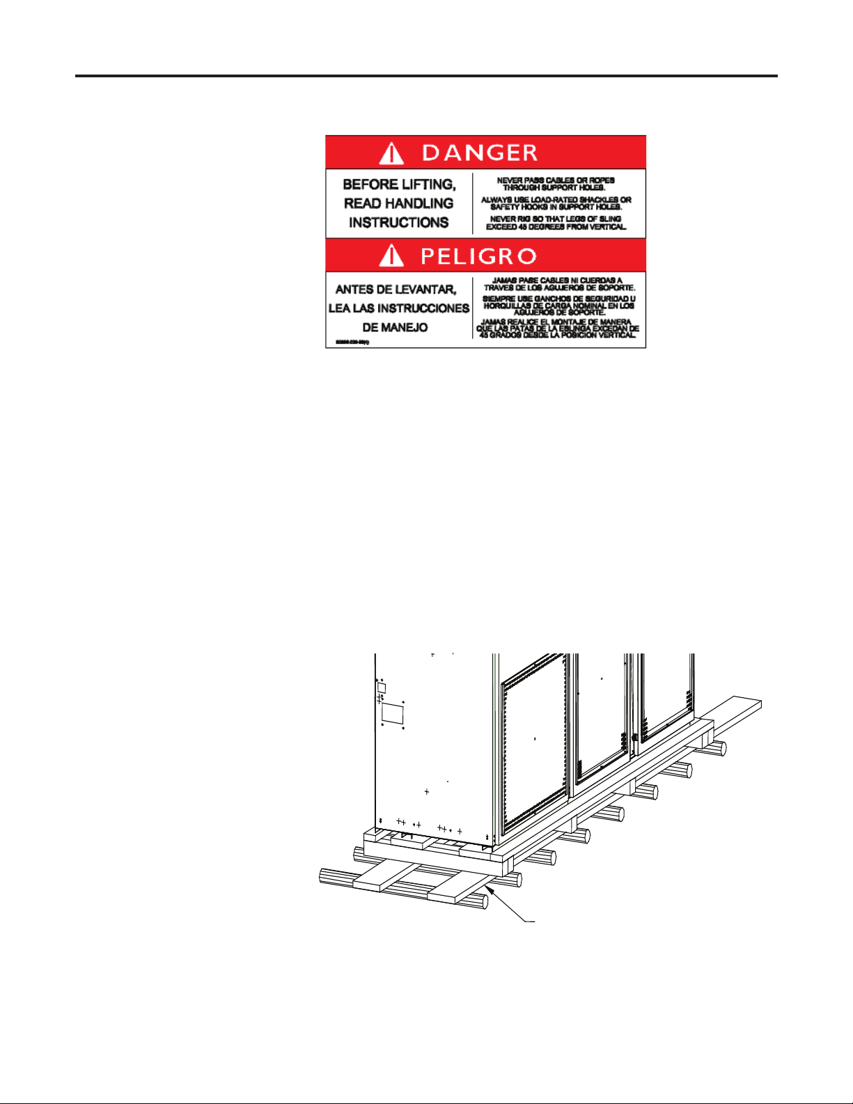
Rod or Pipe Rollers
This method is only suitable when there are no inclines and the controller
is being moved on level fl oor.
Boards 50 mm X 152 mm (2” x 6”) or equivalent and at least 300 mm
longer than the controller must be placed under the shipping skid, as shown
in Figure 3.2.
Carefully ease the shipping skid over the rollers until the equipment weight
is borne on the rollers.
The controller can be rolled to its desired location. Steady the load to prevent
tipping.
Minimum 50 mm x 152 mm (2 in. x 6 in.)
Figure 3.2 – Rod or Pipe Rollers
7712-IN001B-EN-P – June 2013
Page 12

3-4 Transportation and Handling
Fork Lift Truck
A single fork lift truck may be used, extreme caution must be exercised.
1. Insert the forks into openings of the shipping skid from the rear of the
controller.
2. Carefully balance the controller on the forks and apply safety straps.
Shipping Skid Removal
Internal access is required to remove the wooden shipping skid from the
Motor Control Center cabinets. External angle brackets attached to the
enclosure are used to attach the enclosure to the wooden skid.
Remove the angle brackets and the associated hardware.
When the enclosure is lifted by overhead means the wooden skid can be
removed.
7712-IN001B-EN-P – June 2013
Page 13
Equipment Installation
Chapter 4
4.1 Removal of Overhead
Lifting Brackets
and Channels
Before joining to adjacent equipment, it is necessary to remove the lifting
angles, spacer, washer and bolt.
(2) Lifting Angles
Spacer, Washer
and Bolt
Figure 4.1 – Removal of Lifting Bracket
7712-IN001B-EN-P – June 2013
Page 14

4-2 Equipment Installation
4.2 Open MV Door Insert the supplied key into MV door. After the door is unlocked, lift the
door handle up to open the MV door.
Lifting the door handle up unlatches the door allowing it to be opened. DO
NOT force open the doors.
Insert supplied key
and turn to unlock
door handle
Figure 4.2 – Unlocking Door Handle
Figure 4.3 – Lifting Door Handle
7712-IN001B-EN-P – June 2013
Page 15

Equipment Installation 4-3
Remove shipping bracing between contactor cart and structure. Inspect for
shipping damage.
Figure 4.4 – View of Contactor Cart with open door and packing materials removed
4.3 Removal of the
Contactor Cart
Just below the contactor cart door, there are two pin holes that will receive
the pins on the service cart.
Roll service cart up to enclosure and ensure that the cart platform is at the
same elevation of rails on service cart and enclosures are equal.
7712-IN001B-EN-P – June 2013
Page 16
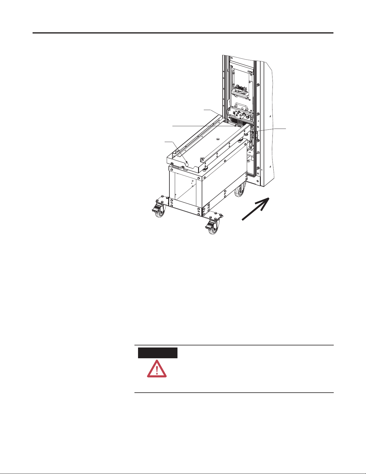
4-4 Equipment Installation
Aligning Holes for
Tapered Pin
Latching Bracket
Lever Handle
Figure 4.5 – Securing Service Cart to Front of the Cabinet
Tapered Pin
Ensure that the cart pins are securely inserted into the enclosure. On the
front of the cart is a locking key that must be engaged to ensure that the
service cart does not come away when the contactor is being removed from
the starter.
Insert cart latch key into the cart latch disengagement and turn the key
clockwise a quarter turn, approximately. Visually ensure latch is disengaged from rail.
The service cart must be securely engaged to the starter
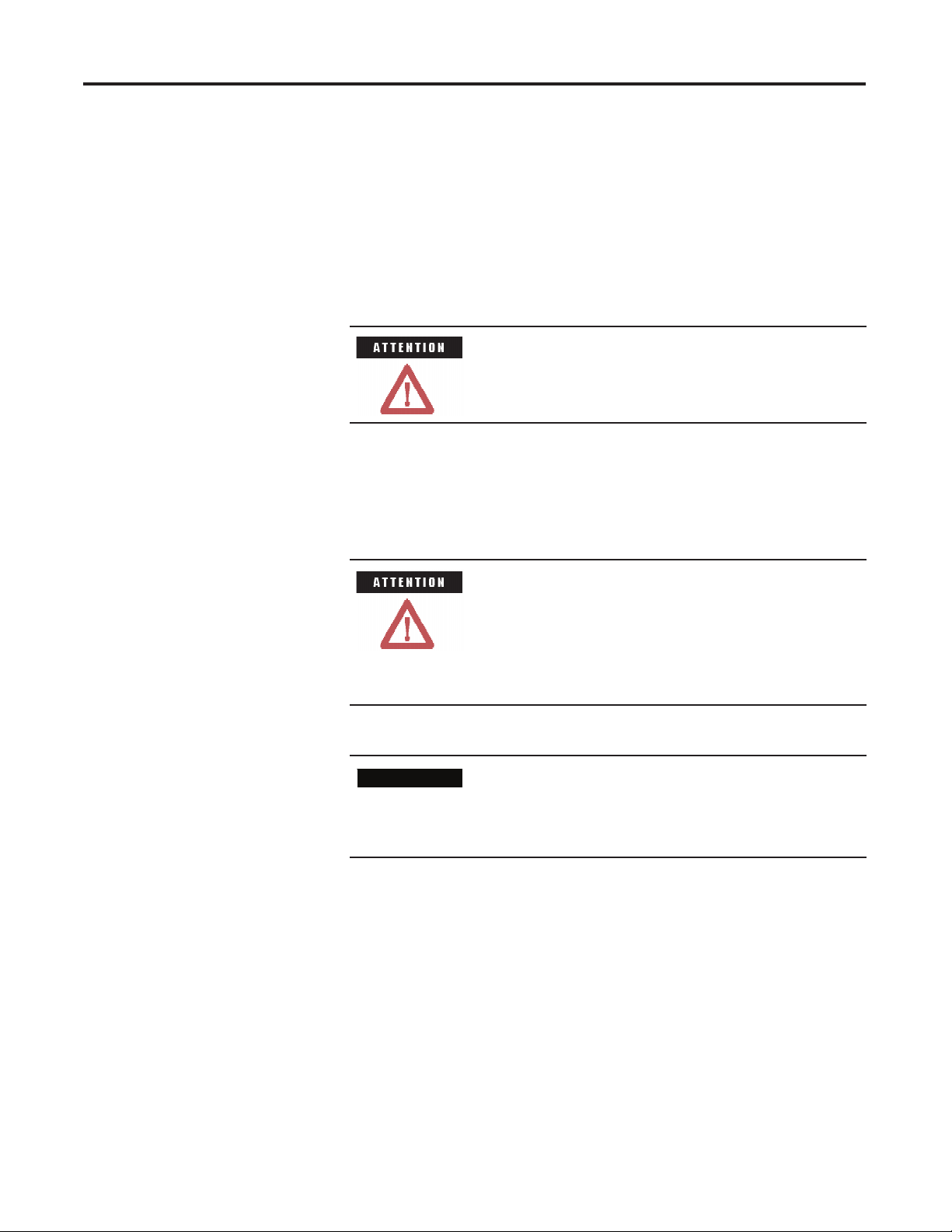
ATTENTION
or there is a possibility that the contactor may fall onto
the fl oor when the contactor is being removed from the
starter. This could result in damage to the contactor and/
or injury to persons.
7712-IN001B-EN-P – June 2013
Page 17

Equipment Installation 4-5
Disengage cart latch
Figure 4.6 – Contactor Cart Latch
Grab handle, keeping key engaged, and fi rmly remove contractor cart from
enclosure onto the service cart.
Figure 4.7 – Contactor Cart Removal Handle
A clear space of 1300 mm is required in front of the
I M P O R T A N TI M P O R T A N T
equipment to facilitate removal of the contactor cart is
required.
I M P O R T A N TI M P O R T A N T
This method of removing the contactor cart is only
valid if the equipment is installed on a level fl oor. If the
equipment is installed on an elevated platform, alternate
means are required. Consult factory for details.
7712-IN001B-EN-P – June 2013
Page 18

4-6 Equipment Installation
Figure 4.8 – Contactor Cart Removal
Figure 4.9 – Contactor Cart Completely Removed
7712-IN001B-EN-P – June 2013
Page 19

Equipment Installation 4-7
Figure 4.10 – Barrier Assembly with Contactor Cart Removed
4.4 Removal of Inter
Compartment Barrier
Figure 4.11 – Removing Barrier Assembly Bolt
Remove bolt that is retaining the barrier assembly between contactor cell
and load terminal cell.
Bolt Securing
Barrier Assembly
Pull aside gasket from the front of the cabinet fl ange to enable removal of
barrier.
7712-IN001B-EN-P – June 2013
Page 20

4-8 Equipment Installation
Figure 4.12 – Setting Aside Gaskets So Barrier Assembly can be Removed
Slide and remove barrier assembly from out of front of the cabinet.
Figure 4.13 – Removal of the Barrier Assembly
7712-IN001B-EN-P – June 2013
Page 21

Equipment Installation 4-9
4.5 Removal of Bottom
Conduit Cover
At the front of the enclosure on the fl oor, you will fi nd the bottom conduit
cover. There are four bolts holding the cover in place. Remove these four
bolts and remove cover.
Remove four bolts
from conduit cover
Figure 4.14 – Bottom Conduit Cover
The starter should now be placed in its fi nal service location. It is important
4.6 Final Product Placement
and Joining of Adjacent
Units
to ensure the MV MCC lineup is in the proper position as the load cables
are to go through the bottom conduit cover. It is also important that the
fi nal installation location for the starter lineup is at a certain minimal distance
from obstructions (e.g. walls and support columns). Refer to Figures 4.16
and 4.17.
7712-IN001B-EN-P – June 2013
Page 22

4-10 Equipment Installation
Control Wire Conduit Opening
1300 mm
Dimensions = inches [mm]
Figure 4.15 – Distance from Obstructions at the Front of Starter Lineup
50 mm
150 mm
150 mm
Load Cable Conduit Opening
Dimensions = inches [mm]
Control Cable Conduit Opening
Mounting Holes for 0.50 [12] dia.
anchor bolts
Figure 4.16 – Distance from Obstructions at the Sides/Back of Starter Lineup
I M P O R T A N TI M P O R T A N T
The channels and external lifting lugs must be removed
prior to mating to any adjacent switchgear components.
7712-IN001B-EN-P – June 2013
I M P O R T A N TI M P O R T A N T
The equipment must be placed on a fl at and level concrete
base that can withstand the weight of the equipment.
Page 23

Equipment Installation 4-11
4.6.1 Mechanical Connections between Enclosures
For fi nding the mechanical connection bolts in the front of the structure,
remove low voltage wire duct cover from the front of the contactor cart
section, and load cable compartment. The covers are held in place by two
bolts each. Each section has these covers that need to be removed.
Low Voltage wire duct cover
in Contactor Compartment
Figure 4.17 – Low Voltage Wire Duct Cover
Inside these LV wire ducts, you will fi nd the bolts needed to connect each
section together.
Connecting bolts
for front of the cabinet
Figure 4.18 – Mechanical Mounting Bolts in the Contactor Compartment
7712-IN001B-EN-P – June 2013
Page 24

4-12 Equipment Installation
In order to fi nd the mechanical connection bolts on the back of the structure,
remove the back panel to get access to the main buss compartment. Remove
the bolts from the bus compartment panel.
Figure 4.19 – Back Access of the Starter
Once removed, you will now see the access to the bus bar compartment.
This compartment also needs to be removed.
7712-IN001B-EN-P – June 2013
Page 25

Equipment Installation 4-13
Figure 4.20 – Back Access Bus Bar Compartment
Once removed, you will now see the exposed bus bars.
7712-IN001B-EN-P – June 2013
Page 26

4-14 Equipment Installation
Figure 4.21 – Exposed Bus Bar Compartment
Looking just inside the Bus Bar Compartment, there will be a series of nuts
attached to the side of the cabinet. Once the adjoining cabinets are positioned
in their fi nal resting location, the cabinets can be secured together with the
bolts provided via the cabinet securing bolts (19 ft-lbs/26 N·m).
Connecting bolts for
the front of the cabinet
Figure 4.22 – Cabinet Securing Bolts at the Back of Bus Bar Compartment
7712-IN001B-EN-P – June 2013
Page 27

Equipment Installation 4-15
4.6.1.1 Joining Incoming Breaker to Starter
Place the breaker and starter beside each in their fi nal position.
Ensure that the two units are in the correct position such that the joining
holes in one cabinet match the opposite bolt hole connections.
Incoming Breaker
(2) Front Junction Points
inside LV panel
(2) Front Junction Points
inside MV panel
Figure 4.23 – Joining Incoming Breaker to Starter
Starter Cabinet
Connecting bolts
to seal around
bus opening
(4) Rear Junction Points
Front flange faces
Figure 4.24 – Aligning Incoming Breaker to Starter
7712-IN001B-EN-P – June 2013
Page 28
4-16 Equipment Installation
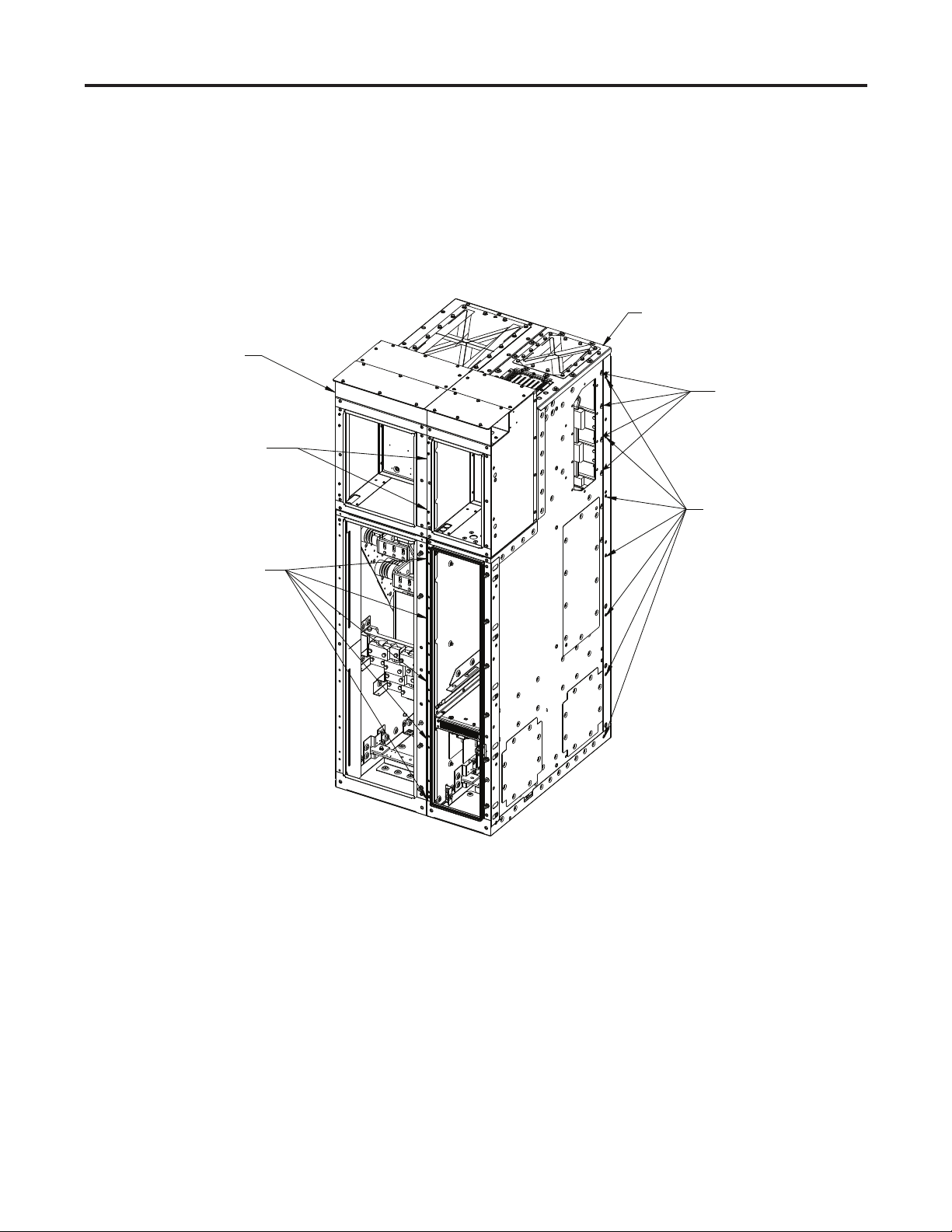
4.6.1.2 Joining Incoming Section to Starter
Place the incoming section and starter beside each other in their fi nal position.
Ensure the two units are in their correct position such that the joining holes
in one cabinet match the opposite bolt hole connections.
Starter Cabinet
Incoming Cabinet
Connecting bolts
to seal around
bus opening
(2) Front junction points
inside LV panel
(7) Rear junction points
(5) Front junction points
inside MV panel
Figure 4.25 – Joining Incoming Section to Starter
7712-IN001B-EN-P – June 2013
Page 29

Equipment Installation 4-17
4.6.1.3 Joining Section to Section
Place the sections beside each other in their fi nal position.
Ensure the two units are in their correct position such that the joining holes
in one cabinet match the opposite bolt hole connections.
Connecting bolts
to seal around
bus opening
(2) Front junction points
inside LV panel
(5) Front junction points
inside MV section
Figure 4.26 – Joining Starter to Starter
(7) Rear junction points
7712-IN001B-EN-P – June 2013
Page 30

4-18 Equipment Installation
4.7 Floor Anchoring Take out front and back lag bolts. Then drill through these holes into the
fl at and level concrete fl oor. The anchor holes accommodate 12 mm (.50”)
hardware. Secure to 75 ft-lb/102 N·m.
Remove bolts from
front anchoring
bolt holes
Figure 4.27 – Front of Cabinet Anchor Bolt Location
Remove bolts from
back anchoring
bolt holes
Figure 4.28 – Back of Cabinet Anchor Bolt Location
ATTENTION
The cabinet must be securely attached to the fl oor or
there is a risk that the starter could fall over.
7712-IN001B-EN-P – June 2013
Page 31

Equipment Installation 4-19
4.8 Connecting to
Load Terminals
Load Terminals U, V, X
Figure 4.29 – Load Terminals at the Front of the Cabinet
With the starter in the fi nal location, and the load cables are now inside the
starter, connect the load cables to the load terminals of the starter. Secure
to 75 ft-lbs/102 N·m.
S H O C K H A Z A R DS H O C K H A Z A R D
Load cables must be securely attached to the starter load
terminals to reduce the impact of electrical arc at this
location.
7712-IN001B-EN-P – June 2013
Page 32

4-20 Equipment Installation
4.9 Ground Bus Linking
Figure 4.30 – Ground Bus Links at the Front of the Cabinet
Slide bus links between sections in the slot. Secure the ground bus link
together with the adjoining section. Secure to 37 ft-lb/51 N·m.
S H O C K H A Z A R DS H O C K H A Z A R D
The ground bus links must be properly secured to ensure
the entire MV MCC line up is properly grounded.
7712-IN001B-EN-P – June 2013
Page 33

Equipment Installation 4-21
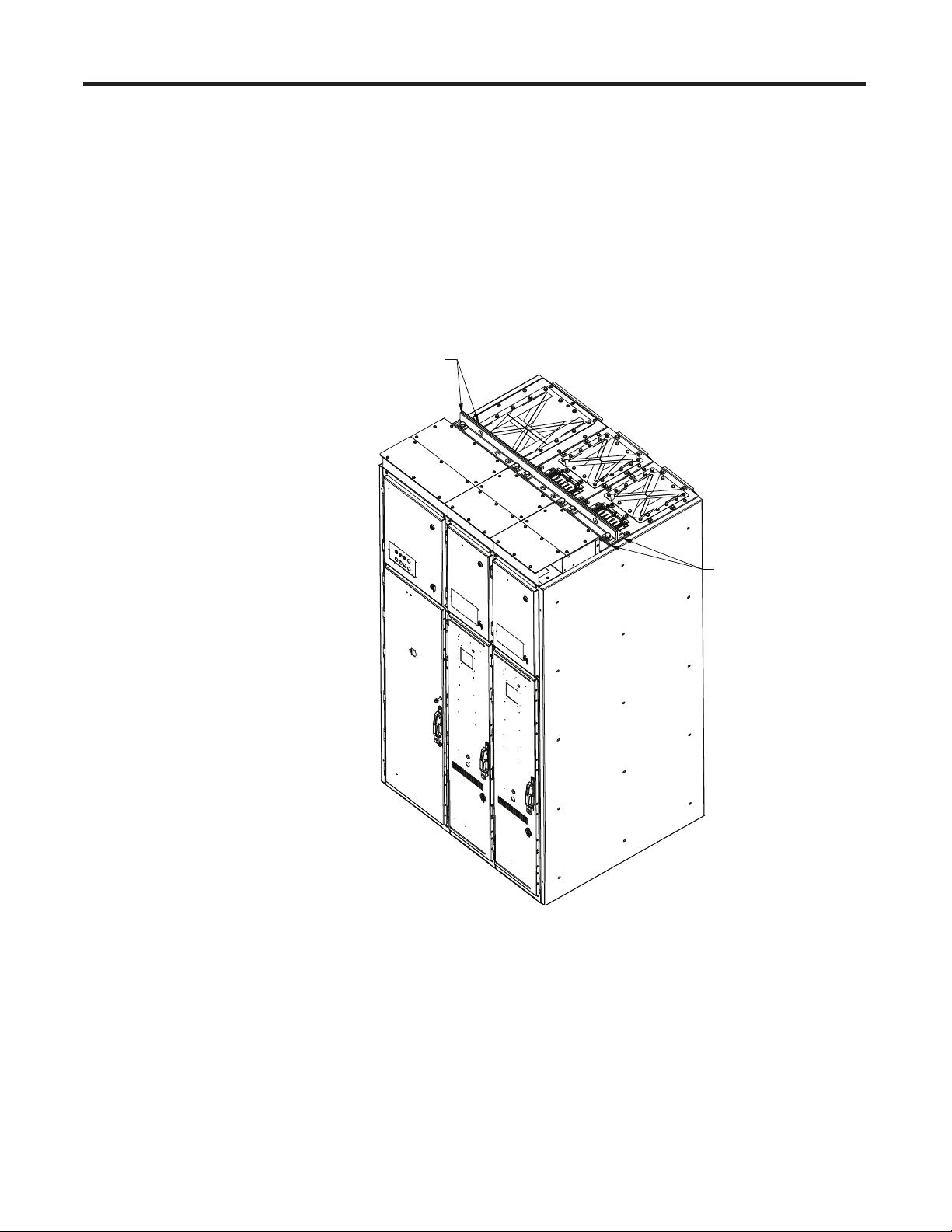
4.10 Main Bus Linking After placing the starters in their fi nal location, the best way to access the
main bus bars are through the top of the starter line up.
Place a ladder at the front of the starters and climb up to the top of the
starter section.
ATTENTION
You may fi nd that you actually have to climb onto the
top MCC lineup. Please be aware that there are arc vents
at the top that cannot have any force applied to them or
they will fall in.
Arc Vents
Some of the bolts
securing top plate
Figure 4.31 – Top View of Cabinet from Front of the Starter
All 16 bolts securing the top plate must be removed before the top plate
can be removed.
Once all 16 bolts have been removed, fl ip back the hinged plate to make it
easier to remove the top plate.
7712-IN001B-EN-P – June 2013
Page 34

4-22 Equipment Installation
Figure 4.32 – Open Top Plate Flap
Remove the top plate while ensuring that the arc vents are not damaged
when you remove the top plate.
Figure 4.33 – Top Plate Removed
7712-IN001B-EN-P – June 2013
Page 35

Equipment Installation 4-23
Once the top plate is off, you will see a partition barrier that will easily
slide up and out of the cabinet.
Figure 4.34 – Inside View of MV Power Compartment
(with Partition Barrier removed)
Once removed, you will easily be able to access the bus bar assembly. The top
bus bar is phase A, the next, phase B and the bar at the bottom is phase C.
Figure 4.35 – Phase A, B, and C Bus Bar Connections
7712-IN001B-EN-P – June 2013
Page 36
4-24 Equipment Installation
Remove the two bolts securing the risers from phase B and C connections.
Starting from Phase C, slide the bus bar link from the left hand cabinet into
the right hand cabinet. Secure the bus bar link to the right hand cabinet
bus bar and then to the left hand cabinet bus bar with the linkage hardware
provided. Secure the bolts to the specifi ed torque value (37 ft-lb/51 N·m).
.
Next, slide the bus bar link from either the left or right cabinets for Phase B.
Secure the bus bar link to the right hand cabinet bus bar and then to the left
hand cabinet bus bar with the linkage hardware provided. Secure the bolts
to the specifi ed torque value (37 ft-lb/51 N·m).
Next, slide the bus bar link from the left hand cabinet into the right hand
cabinet for Phase A. Secure the bus bar link to the right hand cabinet bus
bar and then to the left hand cabinet bus bar with the linkage hardware
provided. Secure the bolts to the specifi ed torque value (37 ft-lb/51 N·m).
S H O C K H A Z A R DS H O C K H A Z A R D
All bus links should be securely attached to avoid risk of
electrical arc.
Figure 4.36 – Phase A, B, and C Bus Bar Connections
The fi nal bus bar links should look like Figure 4.29.
Once the bus bars are connected properly, reverse the procedure from above.
1) Reinsert the partition barrier.
2) Replace the top cover plate.
3) Secure the top cover plate with the 16 bolts that were removed from
before. Secure to 11 ft-lb/14.5 N·m.
7712-IN001B-EN-P – June 2013
Page 37

Equipment Installation 4-25
4.11 Placing the Contactor
Back into the Starter
Upon completion of 4.10, the whole starter must now be placed back
together as it originally was.
1) Re-install the Barrier Assembly from step 4.1.4.
2) Re-install the contactor cart from step 4.1.3.
3) Re-close the MV door from step 4.1.2.
W A R N I N GW A R N I N G
Failure to re-install all components to their original
functional state may lead to personal injury or death,
property damage, or economic loss.
7712-IN001B-EN-P – June 2013
Page 38

4-26 Equipment Installation
7712-IN001B-EN-P – June 2013
Page 39

Chapter 5
OneGear™ Standard Plenum Assembly Procedure
Procedure The following is an illustrated procedure for assembling the standard plenum
to OneGear™ cabinetry.
1. Use drawing 81021-288 as a general guideline for fi xing the panels.
This assembly drawing should be supplied with the order.
2. Identify the right materials necessary for this operation (see following
fi gures).
• Connecting brackets assembly to ABB switchgear, qty. 1
(81021-288-92/93)
• 7712/7719 Plenum assembly, qty. 2 (81021-288-91)
• OneGear connecting brackets assembly, qty. 1
(81020-288-91)
• If a 7712 or 7791 is ordered there will be an extension and end components included (81021-288-60/62, 81021-288-61, and 81021-28885/86/89/90)
• Hardware (M8 HHCS - 29107-304-04, Flat washer 19 mm (0.75”) OD,
Flat washer 28 mm (1.125”) OD, Lock washer, M6 self-tapping
screws 29171-640-01 for extension)
• 25 mm (1”) Gasket and silicone tube
Figure 5.1 – Components for plenum assembly
7712-IN001B-EN-P – June 2013
Page 40

5-2 OneGear™ Standard Plenum Assembly Procedure
3. Install the switchgear gas duct per manufacturer’s instructions
(e.g. ABB UniGear type ZS1 – Standard Gas Duct Assembling Procedure).
4. Locate the ABB connecting adapter plate (81023-965-51/52) for
connecting to the switchgear using M8 hardware (see Figure 5.2a).
Figure 5.2a – Attaching adapter plate to switchgear
5. Locate the front inner bracket (81021-958-51) for connecting to
switchgear temporarily using M8 hardware (see Figure 5.2b).
Figure 5.2b – Attaching front inner bracket
6. Apply gasket to the bottom fl ange of all front and rear assemblies (refer
to Figure 5.3).
7712-IN001B-EN-P – June 2013
Page 41

OneGear™ Standard Plenum Assembly Procedure 5-3
Figure 5.3 – Gasket location
7. Locate the mounting holes on top of the OneGear™ unit to mount the
front and rear assembly (shown in Figure 5.4).
Mounting Holes (Rear)
Mounting Holes (Front)
Figure 5.4 – Mounting location for plenum
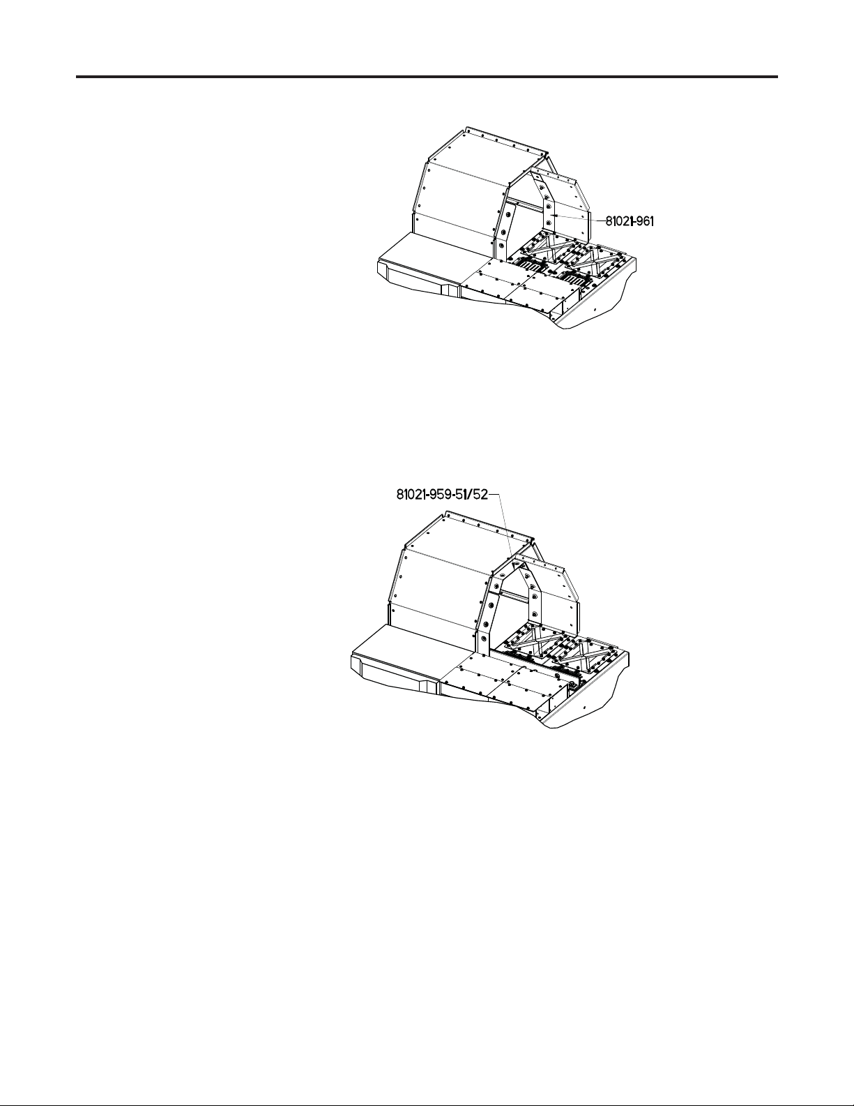
8. Take the rear plate (81021-070-01/02) of 7712/7719 plenum assembly,
position it as shown in Figure 5.5a, and connect it to the adapter plate
and OneGear top plate using the rear inner bracket (81021-961-51) and
M8 hardware (M8 HHCS, 28 mm [1.125"] OD fl at washers and lock
washer).
7712-IN001B-EN-P – June 2013
Page 42
5-4 OneGear™ Standard Plenum Assembly Procedure
Figure 5.5a – Attaching rear inner bracket and rear plate
9. Locate the top inner bracker (81021-959-51/52) for connecting to
switchgear temporarily using M8 hardware (see Figure 5.2b).
Figure 5.5b – Attaching top inner bracket
10. Take the front plate (81021-068-01/02) of 7712/7719 plenum assembly,
position it as shown in Figure 5.5c, and connect to OneGear top plate
using M8 hardware (M8 HHCS, 28 mm [1.25"] OD fl at washers and
lock washer).
7712-IN001B-EN-P – June 2013
Page 43

OneGear™ Standard Plenum Assembly Procedure 5-5
Figure 5.5c – Starter Plenum mounted on top of cabinet
11. Attach the outside backet (81023-075-02) at the front using M8 hardware
(M8 HHCS, 19 mm (0.75”) OD fl at washers and lock washers). Refer
to Figure 5.6.
Figure 5.6 – Attaching front outer bracket
7712-IN001B-EN-P – June 2013
Page 44

5-6 OneGear™ Standard Plenum Assembly Procedure
12. Remove the temporary fastened hardware from Step 5; the front inner
bracket should stay in place as a result of Step 11.
13. Attach the outer side bracket that is on an angle (81023-075-01) at the
front of the plenum using M8 hardware (M8 HHCS, 19 mm [0.75"]
OD fl at washers and lock washer). Refer to Figure 5.7.
Figure 5.7 – Attaching front outer bracket on angle
14. Remove the temporarily fastened hardware from Step 9; the top inner
bracket should stay in place as a result of Step 13.
15. Attach the top outer side bracket (81023-075-04/05) at the top of the
plenum using M8 hardware (M8 HHCS, 19 mm [0.75"] OD fl at washers
and lock washer). Refer to Figure 5.8.
7712-IN001B-EN-P – June 2013
Figure 5.8 – Attaching top outer bracket
Page 45
OneGear™ Standard Plenum Assembly Procedure 5-7
At this point, the OneGear™ SMC plenum should be completely attached
to the switchgear equipment. Apply silicone to gaps or holes located at
bends and corners. Continue with installation of the OneGear™ plenum
components.
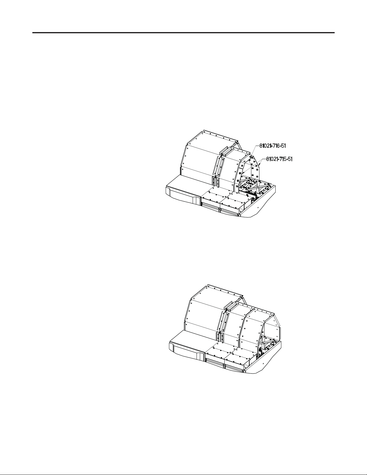
16. Temporarily attach the inner rear and front bracket (81021-715-51)
and top inner bracket (81021-716-51) using M8 hardware as shown in
Figure 5.9.
Figure 5.9 – Attaching top, front and rear inner bracket
17. Take front and rear plates of 7712/7719 plenum assembly, position
it as shown in Figure 5.10, and connect it OneGear top plate using
M8 hardware (M8 HHCS, 28 mm (1.125”) OD fl at washers and lock
washer).
Figure 5.10 – Starter plenum mounted on top of cabinet
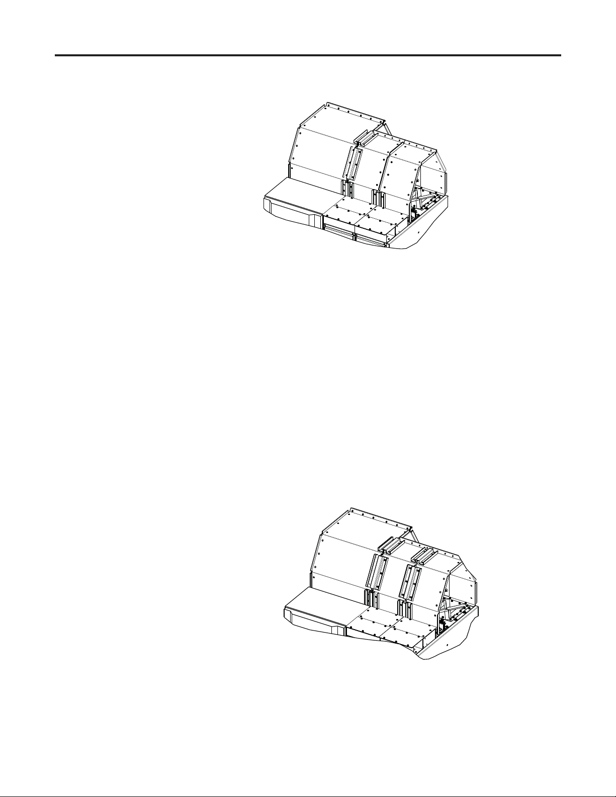
18. Attach the outside bracket (81021-272-02) at the front and rear using
the M8 hardware (M8 HHCS, 19 mm (0.75”) OD fl at washers and lock
washer). Refer to Figure 5.11.
7712-IN001B-EN-P – June 2013
Page 46
5-8 OneGear™ Standard Plenum Assembly Procedure
Figure 5.11 – Attaching front and rear outer bracket
19. Remove the temporary fastened hardware (only for front and rear inner
bracket) from Step 16; the front and rear inner bracket should stay in
place as a result of Step 18.
20. Attach the outer side bracket that is on an angle (81021-272-01) at the
front and rear of the plenum using M8 hardware (M8 HHCS, 19 mm
(0.75”) OD fl at washers and lock washer).
21. Remove the rest of temporary fastened hardware from Step 16; the top
inner bracket should stay in place as a result of Step 20.
22. Attach the top outer side bracket (81021-272-03) at the top of the
plenum using M8 hardware (M8 HHCS, 19 mm (0.75”) OD fl at
washers and lock washer). Refer to Figure 5.12.
Figure 5.12 – Attaching top, front and rear outer bracket
7712-IN001B-EN-P – June 2013
Page 47
5-9 OneGear™ Standard Plenum Assembly Procedure
Two sections of the OneGear™ plenum should now be fully installed .
Apply
silicone to gaps or holes located at bends and corners.
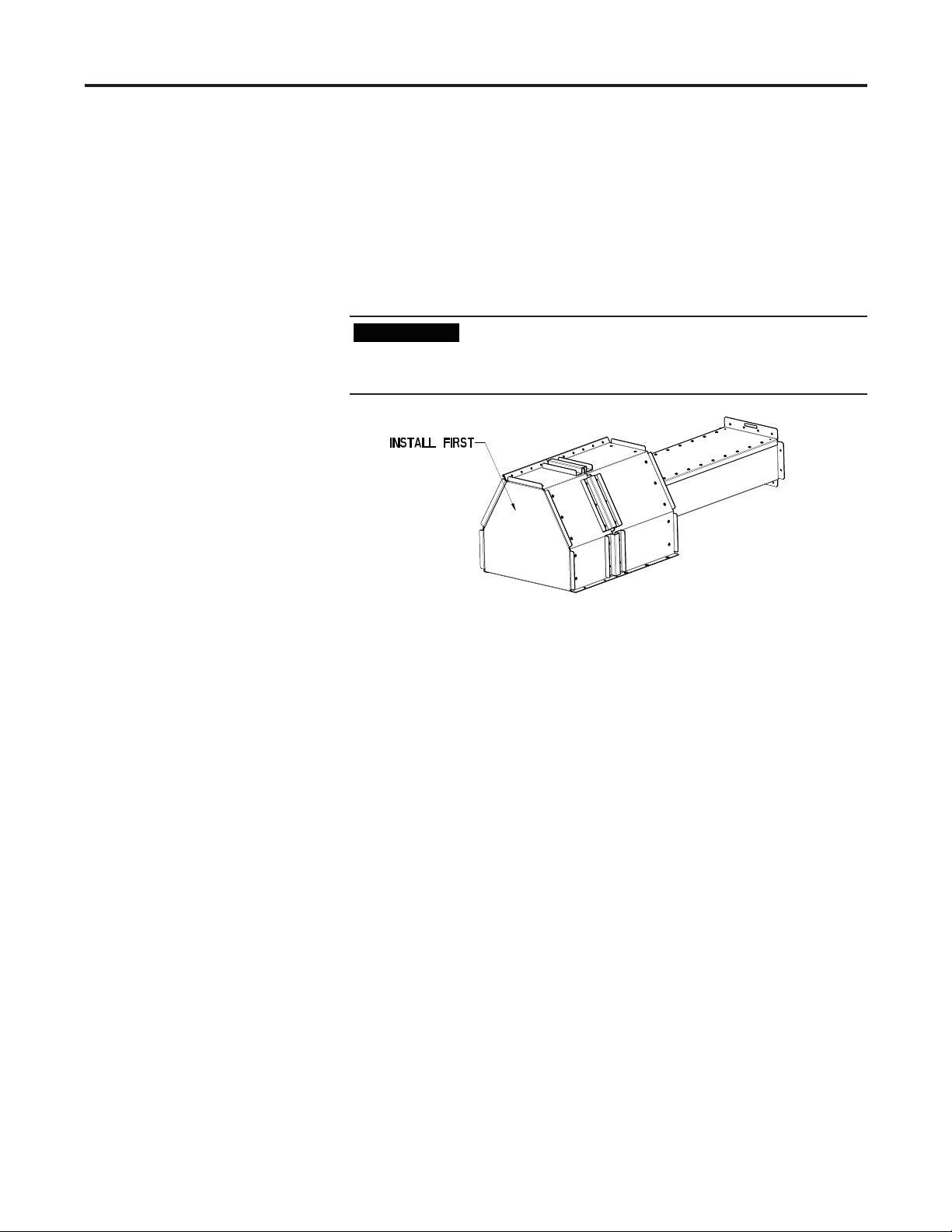
23. If a Bulletin 7712/7791 product is ordered, an end plate (81021-28889/90) and extension with screen will be required (81021-288-60/62,
and 81021-288-61). Install the end plate with M8 hardware.
If an end plate is ordered with no exit hole, it must be
I M P O R T A N TI M P O R T A N T
installed first or it will be very difficult to attach to the
top plate, see Figure 5.13.
Figure 5.13 – One Gear unit on the end (7712)
24. Attached the extension to the end plate using M6 self-tapping screws.
Subsequent extensions are attached using M8 hardware.
For Bulletin 7712and 7791 equipment, switchgear is provided on both
sides of the SMC. Therefore, Steps 4-15 will need to be repeated using the
switchgear front and rear assembly.
7712-IN001B-EN-P – June 2013
Page 48

5-10 OneGear™ Standard Plenum Assembly Procedure
7712-IN001B-EN-P – June 2013
Page 49

Torque Values for Hardware
The following table contains the recommended torquing values for hardware
required to fasten electrical connections (bus-bus or bus-fl exible bus links).
Appendix A
Hardware
M6 6.0 4.4
M8 14.0 11.0
M10 29.0 21.0
M12 50.0 37.0
M16 124.0 91.0
Recommended Torque
N· m Lb.ft.
7712-IN001B-EN-P – March 2013
Page 50

A-2 Torque Values for Hardware
7712-IN001B-EN-P – June 2013
Page 51

Page 52

Medium Voltage Products, 135 Dundas Street, Cambridge, ON, N1R 5X1 Canada, Tel: (1) 519.740.4100, Fax: (1) 519.623.8930, www.ab.com/mvb
Publication 7712-IN001B-EN-P – June 2013 Copyright © 2013 Rockwell Automation, Inc. All rights reserved. Printed in Canada.
 Loading...