

Page 1

Installation Instructions
Medium Voltage SMC™ OEM Components (10…15 kV)
Publication 7703E-IN001E-EN-P
Page 2
Important User Information
IMPORTANT
Read this document and the documents listed in the additional resources section about installation, configuration, and
operation of this equipment before you install, configure, operate, or maintain this product. Users are required to
familiarize themselves with installation and wiring instructions in addition to requirements of all applicable codes, laws,
and standards.
Activities including installation, adjustments, putting into service, use, assembly, disassembly, and maintenance are required
to be carried out by suitably trained personnel in accordance with applicable code of practice.
If this equipment is used in a manner not specified by the manufacturer, the protection provided by the equipment may be
impaired.
In no event will Rockwell Automation, Inc. be responsible or liable for indirect or consequential damages resulting from the
use or application of this equipment.
The examples and diagrams in this manual are included solely for illustrative purposes. Because of the many variables and
requirements associated with any particular installation, Rockwell Automation, Inc. cannot assume responsibility or
liability for actual use based on the examples and diagrams.
No patent liability is assumed by Rockwell Automation, Inc. with respect to use of information, circuits, equipment, or
software described in this manual.
Reproduction of the contents of this manual, in whole or in part, without written permission of Rockwell Automation,
Inc., is prohibited.
Throughout this manual, when necessary, we use notes to make you aware of safety considerations.
WARNING: Identifies information about practices or circumstances that can cause an explosion in a hazardous environment,
which may lead to personal injury or death, property damage, or economic loss.
ATTENTION: Identifies information about practices or circumstances that can lead to personal injury or death, property
damage, or economic loss. Attentions help you identify a hazard, avoid a hazard, and recognize the consequence.
Identifies information that is critical for successful application and understanding of the product.
Labels may also be on or inside the equipment to provide specific precautions.
SHOCK HAZARD: Labels may be on or inside the equipment, for example, a drive or motor, to alert people that dangerous
voltage may be present.
BURN HAZARD: Labels may be on or inside the equipment, for example, a drive or motor, to alert people that surfaces may
reach dangerous temperatures.
ARC FLASH HAZARD: Labels may be on or inside the equipment, for example, a motor control center, to alert people to
potential Arc Flash. Arc Flash will cause severe injury or death. Wear proper Personal Protective Equipment (PPE). Follow ALL
Regulatory requirements for safe work practices and for Personal Protective Equipment (PPE).
Allen-Bradley, Rockwell Software, Rockwell Automation, PowerFlex, and TechConnect are trademarks of Rockwell
Automation, Inc.
Trademarks not belonging to Rockwell Automation are property of their respective companies.
Page 3

Summary of Changes
This manual contains new and updated information. Changes throughout this
revision are marked by change bars, as shown to the right of this paragraph.
New and Updated Information
This table contains the changes made to this revision.
Top ic Pag e
Migrated manual to FrameMaker
Updated PowerBrick catalog numbers and removed footnotes about them 11
Added 580 A to PowerBrick specifications table 12
Updated PowerBrick dimension and arrangement diagrams 14, 15, 16
Removed 160/340 A description from power circuit wiring diagram 38
Added 580 A to component derating table 47
Added 580 A to PowerBrick replacements table 53
Added Index 55
Rockwell Automation Publication 7703E-IN001E-EN-P - July 2014 3
Page 4

Summary of Changes
Notes:
4 Rockwell Automation Publication 7703E-IN001E-EN-P - July 2014
Page 5

Introduction
Table of Contents
Chapter 1
Scope . . . . . . . . . . . . . . . . . . . . . . . . . . . . . . . . . . . . . . . . . . . . . . . . . . . . . . . . . . . . . 7
Additional Publications . . . . . . . . . . . . . . . . . . . . . . . . . . . . . . . . . . . . . . . . . . . . 7
Chapter 2
Receiving and General Information
PowerBrick™ Installation
Control Component Installation
Receiving . . . . . . . . . . . . . . . . . . . . . . . . . . . . . . . . . . . . . . . . . . . . . . . . . . . . . . . . . . 9
Handling Procedures for Electrostatic Sensitive Devices . . . . . . . . . . . . . . . 9
Standards and Codes . . . . . . . . . . . . . . . . . . . . . . . . . . . . . . . . . . . . . . . . . . . . . . . 9
Chapter 3
Identification . . . . . . . . . . . . . . . . . . . . . . . . . . . . . . . . . . . . . . . . . . . . . . . . . . . . 11
Sizing the Enclosure . . . . . . . . . . . . . . . . . . . . . . . . . . . . . . . . . . . . . . . . . . . . . . 12
Dimensions. . . . . . . . . . . . . . . . . . . . . . . . . . . . . . . . . . . . . . . . . . . . . . . . . . . . . . 13
Torque Requirements . . . . . . . . . . . . . . . . . . . . . . . . . . . . . . . . . . . . . . . . . . . . 13
PowerBrick Mounting. . . . . . . . . . . . . . . . . . . . . . . . . . . . . . . . . . . . . . . . . . . . 13
Typical Mounting Arrangement, 10…12 kV PowerBrick System . . . . . 15
Typical Mounting Arrangement, 12.1…14.4 kV PowerBrick System. . 16
Power Connections . . . . . . . . . . . . . . . . . . . . . . . . . . . . . . . . . . . . . . . . . . . . . . 17
Grounding . . . . . . . . . . . . . . . . . . . . . . . . . . . . . . . . . . . . . . . . . . . . . . . . . . . . . . 20
PowerBrick Operating Restrictions . . . . . . . . . . . . . . . . . . . . . . . . . . . . . . . . 20
Voltage Sensing Board Dimensions . . . . . . . . . . . . . . . . . . . . . . . . . . . . . . . . 21
Mounting and Connecting the Voltage Sensing Board . . . . . . . . . . . . . . 21
Current Loop Gate Drive Power Assembly (CLGD) . . . . . . . . . . . . . . . . 23
Chapter 4
Interface Board Installation . . . . . . . . . . . . . . . . . . . . . . . . . . . . . . . . . . . . . . . 27
Interface Board Connections. . . . . . . . . . . . . . . . . . . . . . . . . . . . . . . . . . . . . . 29
SMC Flex Control Module . . . . . . . . . . . . . . . . . . . . . . . . . . . . . . . . . . . . . . . 29
EMC Compliance. . . . . . . . . . . . . . . . . . . . . . . . . . . . . . . . . . . . . . . . . . . . . . . . 29
Enclosure . . . . . . . . . . . . . . . . . . . . . . . . . . . . . . . . . . . . . . . . . . . . . . . . . . . . 29
Wiring . . . . . . . . . . . . . . . . . . . . . . . . . . . . . . . . . . . . . . . . . . . . . . . . . . . . . . 30
Control Power. . . . . . . . . . . . . . . . . . . . . . . . . . . . . . . . . . . . . . . . . . . . . . . . . . . 30
Control Voltage . . . . . . . . . . . . . . . . . . . . . . . . . . . . . . . . . . . . . . . . . . . . . . 30
Control Wiring . . . . . . . . . . . . . . . . . . . . . . . . . . . . . . . . . . . . . . . . . . . . . . 31
Control Terminal Designations . . . . . . . . . . . . . . . . . . . . . . . . . . . . . . . . . . . 31
Connecting Interface Board to Voltage Sensing Board. . . . . . . . . . . . . . . 32
Connecting Fiber Optic Multiplexer Board to Gate Driver Board . . . . 33
Additional Control Components. . . . . . . . . . . . . . . . . . . . . . . . . . . . . . . . . . 34
Main and Bypass Switching Device
Installation
Chapter 5
Introduction. . . . . . . . . . . . . . . . . . . . . . . . . . . . . . . . . . . . . . . . . . . . . . . . . . . . . 35
Main Contactor or Circuit Breaker . . . . . . . . . . . . . . . . . . . . . . . . . . . . . . . . 35
Bypass Contactor or Circuit Breaker. . . . . . . . . . . . . . . . . . . . . . . . . . . . . . . 35
Rockwell Automation Publication 7703E-IN001E-EN-P - July 2014 5
Page 6

Table of Contents
Chapter 6
Typical Wiring Diagrams
Final Test Procedures
Component Deratings
Typical Schematic Diagrams
Wiring Diagrams . . . . . . . . . . . . . . . . . . . . . . . . . . . . . . . . . . . . . . . . . . . . . . . . . 37
Chapter 7
Final Test Procedures . . . . . . . . . . . . . . . . . . . . . . . . . . . . . . . . . . . . . . . . . . . . . 39
Dielectric Test . . . . . . . . . . . . . . . . . . . . . . . . . . . . . . . . . . . . . . . . . . . . . . . . . . . 40
Additional Tests . . . . . . . . . . . . . . . . . . . . . . . . . . . . . . . . . . . . . . . . . . . . . . . . . 41
Programming . . . . . . . . . . . . . . . . . . . . . . . . . . . . . . . . . . . . . . . . . . . . . . . . . . . . 41
MV SMC Flex Module. . . . . . . . . . . . . . . . . . . . . . . . . . . . . . . . . . . . . . . . 41
Voltage Sensing Module . . . . . . . . . . . . . . . . . . . . . . . . . . . . . . . . . . . . . . . . . . 41
Power Supply Test. . . . . . . . . . . . . . . . . . . . . . . . . . . . . . . . . . . . . . . . . . . . . . . . 42
Start-Up. . . . . . . . . . . . . . . . . . . . . . . . . . . . . . . . . . . . . . . . . . . . . . . . . . . . . . . . . 46
Spare Parts. . . . . . . . . . . . . . . . . . . . . . . . . . . . . . . . . . . . . . . . . . . . . . . . . . . . . . . 46
Appendix A
Deratings Specifications. . . . . . . . . . . . . . . . . . . . . . . . . . . . . . . . . . . . . . . . . . . 47
Appendix B
Introduction . . . . . . . . . . . . . . . . . . . . . . . . . . . . . . . . . . . . . . . . . . . . . . . . . . . . . 49
Spare Parts
Index
Appendix C
PowerBricks . . . . . . . . . . . . . . . . . . . . . . . . . . . . . . . . . . . . . . . . . . . . . . . . . . . . . 53
6 Rockwell Automation Publication 7703E-IN001E-EN-P - July 2014
Page 7

Introduction
Chapter 1
Scope
Additional Publications
This document pertains to the Bulletin 7703E SMC OEM components for 1015 kV. These components allow an OEM to fabricate a medium voltage soft
starting solution.
Most of the components described herein are provided in various 7703E kits;
however, some of the devices described are not provided. These must be acquired
separately.
A key part of the Bulletin 7703E components is the power stack assembly which
uses PowerBrick™ technology. PowerBricks are a superior means of packaging
SCRs, heatsinks, passive devices (for circuit protection) and gate drive circuit
boards. Each PowerBrick is a self-contained assembly with inherent insulation
and flexible mounting features. PowerBricks are easily connected in series to
service the required system voltage level.
PowerBricks are provided as a set of components used to create a three-phase
assembly (refer to Figure 1 on page 11
applied with other Bulletin 7703E control components and power devices, in
forming a complete solution.
Please refer to Medium Voltage SMC Flex Motor Controller, Bulletin 1503E,
1560E, 1562E User Manual 1560E-UM051_-EN-P
about the functionality of some of the Bulletin 7703E products. This document
contains the following information for the MV SMC Flex:
• Commissioning
• Maintenance and Troubleshooting
• Parameter List
). Each form of PowerBrick assembly is
for additional information
To order additional copies of Instruction Manuals for all Rockwell Automation
medium voltage products, please contact a Rockwell Automation sales office or
your local distributor.
Rockwell Automation Publication 7703E-IN001E-EN-P - July 2014 7
Page 8

Chapter 1 Introduction
Notes:
8 Rockwell Automation Publication 7703E-IN001E-EN-P - July 2014
Page 9

Receiving and General Information
IMPORTANT
Chapter 2
Receiving
Handling Procedures for Electrostatic Sensitive Devices
Refer to Getting Started, General Handling Procedures for Medium Voltage
Controllers – Publication MV-QS050_-EN-P
your shipment and contains information regarding receiving, unpacking, initial
inspection, handling, storage, and site preparation.
ATT EN TI ON : Printed circuit boards contain components that can be damaged
by electrostatic charges that build up on personnel during normal activities.
Exercise the following precautions when handling electrostatic sensitive
devices. Failure to do so may damage the device and render it inoperable.
To guard against electrostatic damage (ESD) to equipment, the following
precautions should be observed when handling electrostatic sensitive devices.
1. Use a grounding wrist strap to minimize the build up of static charges on
personnel.
2. Handle the module by the edges and avoid touching components or
printed circuit paths.
3. Store devices with sensitive components in the conductive packaging that
the module is shipped in.
. This document is included with
These precautions are the minimum requirements for guarding against ESD. For
more information refer to Guarding Against Electrostatic Damage –
Publication ICCG-4.3. See the Additional Publications section for information
on obtaining this document.
Standards and Codes
It is recommended that the user be familiar with the following safety and
design standards and codes, and any additional local codes that a medium
voltage controller must comply with:
• CEC (Canadian Electrical Code)
• CSA 22.2 No. 253 (Canadian Standards Association) – Medium Voltage
AC Contactors, Controllers and Control Centers
• NEC (National Electrical Code)
Rockwell Automation Publication 7703E-IN001E-EN-P - July 2014 9
Page 10

Chapter 2 Receiving and General Information
• NEMA ICS Standards (National Electrical Manufacturers’ Association)
• OSHA (Occupational Safety and Health Administration)
• UL 50 (Underwriters Laboratories) – Enclosures for Electrical Equipment
• UL 347B (Underwriters Laboratories) – Medium Voltage Motor
Controllers
• UL 508 (Underwriters Laboratories) – Industrial Control Equipment
• IEC 60204-1 – Safety of Machinery – Electrical Equipment of Machines,
Part 1: General Requirements
• IEC 62271-200 – AC Metal Enclosed Switchgear and Control Gear for
Rated Voltages Above 1kV and up to 52 kV (formerly IEC 60298)
• IEC 62271-106 – High Voltage Alternating Current Contactors (formerly
IEC 604701
• IEC 60529 – Degrees of Protection Provided by Enclosures (IP Code)
• IEC 62271-1 – Common Clauses for High Voltage Switchgear and
Control Gear Standards
• ICS1– Industrial Control and Systems General Requirements
• ICS3 Part 2 – Industrial Control and Systems - Medium Voltage
Controllers Rated 2001-7200V AC
10 Rockwell Automation Publication 7703E-IN001E-EN-P - July 2014
Page 11

PowerBrick™ Installation
Chapter 3
Identification
A PowerBrick is shown in Figure 1.
Figure 1 - Single-phase PowerBrick
Several PowerBricks are supplied as a loose set of components to service a
particular voltage and current. Verify the voltage and current rating of the OEM
power stacks by examining the shipping label and referencing it to the
information in Ta b l e 1
.
Table 1 - PowerBrick Options and Catalog Numbers
Catalog Number
7703E-PPMT
7703E-PPMA 340
7703E-PPMC 580
7703E-PPNT
7703E-PPNA 340
7703E-PPNC 580
(1) The OEM is responsible for ordering and installing the correct format for the current loop gate drive conductor conduit/CT assembly
(refer to the Installation Instructions, publication 7703E-IN008_-EN-P
(2) Voltage ranges: 12000 = 10000…12000V (5 PowerBricks in series per phase)
Rockwell Automation Publication 7703E-IN001E-EN-P - July 2014 11
(1)
13800 = 12001…14400V (6 PowerBricks in series per phase)
Voltag e
12000V
13800V
(2)
3 phase, 50/60 Hz
for additional details.)
Current (Amps)
160
160
Page 12
Chapter 3 PowerBrick™ Installation
In addition to the PowerBricks, a voltage sensing board is to be connected in the
power circuit. Ta b l e 2
Table 2 - Voltage Sensing Board Catalog Number
Catalog Number Voltage Sensing Board Input (3 phase, 50/60 Hz)
7703E-VSM 10,000…12,000V
7703E-VSN 12,001…14,400V
lists the voltage sensing board catalog numbers.
Sizing the Enclosure
Description 160 A, 340 A
Input Voltages
(50/60 Hz)
Ambient Temperature 0 °C…40 °C (32 °F…104 °F)
Power Sec tion
(for 3 phases)
Repetitive Peak Inverse
Volt age R ating
Thermal Capacity
dv/dt Protection R.C. Snubber Network
Maximum Heat
Dissipation (kW)
Altitude
Net Shipping Weight
(3 phases)
Weig ht
kg (lbs)
(1)
10,000…12,000V
12,001…14,400V
3 phase, +10%, -15%
30 SCR at 10…12 kV
36 SCR at 12.1…14.4 kV
10 to12 kV…32,500 PIV
12.1…14.4 kV…39,000 PIV
600% of FLA, 10 seconds
450% of FLA, 30 seconds
Start or Stop Cycle (at 450% FLA)
10,000…12,000V 27 57 98 0.5
12,001…14,400V 32 69 117 0.5
0…1000 m (0…3,300 ft)
(See Controller Deratings Table on page 6, Publication 1503-BR010F-EN-P
Rating (kV) 10…12 12.1…14.4
570 (1260) 684 (1512)
ATT EN TI ON : The enclosure for the power stack assemblies must be adequately
sized to provide sufficient airflow to cool the units. Failure to provide adequate
cooling may result in reduced duty cycles or component failure.
Use the data in Ta b l e 3 to assist in calculating the enclosure size.
Table 3 - PowerBrick Specifications
160 A 340 A 580 A Continuous
)
(2)
(1) It may be possible to offer extended start times at reduced current or ambient temperature. Please consult Rockwell Automation factory for assistance.
(2) After bypass contactor/breaker is closed.
12 Rockwell Automation Publication 7703E-IN001E-EN-P - July 2014
Page 13
PowerBrick™ Installation Chapter 3
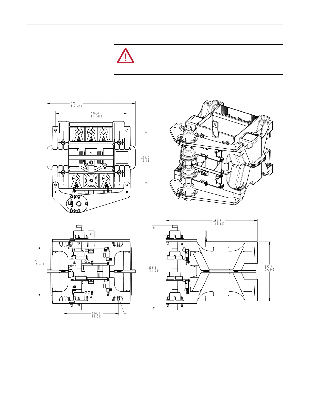
Dimensions
Torque Requirements
Refer to Figure 2, Figure 3, and Figure 4 for PowerBrick dimensions and
mounting.
All electrical connections must be torqued to the specifications shown in Ta b l e 4 .
ATT EN TI ON : Ensure that all electrical connections are torqued to the correct
specification. Failure to do so may result in damage to the equipment and/or
injury to personnel.
Table 4 - Torque Requirements
Hardware Recommended Torque
¼-20 thread cutting housing assembly screws 7 N•m [62 lb•in]
M5 3.4 N•m [30 lb•in]
Control Wire Terminals 0.2…0.4 N•m [2.0…3.3 lb•in]
CLGD Power Assembly Terminals 5.6 N•m [50 lb•in]
SMC Flex Control Module Terminals 0.6 N•m [5in•lb]
M8, Capacitor Lugs
M8, All others
M10 29 N•m [250 lb•in]
7.5 N•m [66 lb•in]
14 N•m [120 lb•in]
PowerBrick Mounting
PowerBricks are to be mounted in a vertical orientation in order to provide
adequate component cooling. Mount the PowerBricks in a suitable location using
the mounting holes provided in the assembly (refer to Figure 2
). Use
M8 (5/16 in.) or similar hardware for the mounting hole dimensions of
10.7 x 15.9 mm (0.421 x 0.625 in.).
PowerBricks are provided with two methods for mounting (as shown in
Figure 2
). The PowerBricks can be mounted to a vertical surface using the four
mounting locations on the rear face, or they can be mounted to a horizontal
surface using the four mounting locations on the base.
Note: Using either mounting option requires space above and below each phase
assembly (refer to Figure 3
and Figure 4).
Rockwell Automation Publication 7703E-IN001E-EN-P - July 2014 13
Page 14
Chapter 3 PowerBrick™ Installation
Top View
Front View
Side View
Mounting holes for
M8 [5/16] hardware
(4) places
ATT EN TI ON : Maintain sufficient clearance between the power phases and
between phases and grounded surfaces. Refer to local electrical codes to
determine the required clearance. Failure to do so may result in injury to
personnel or damage to the equipment.
Figure 2 - Single PowerBrick Dimensions (1000/2400V)
14 Rockwell Automation Publication 7703E-IN001E-EN-P - July 2014
Page 15
PowerBrick™ Installation Chapter 3
Front View
Typical spacing to ground metallic enclosure
components. Spacing may be reduced through the
full use of suitable insulation systems.
Side View
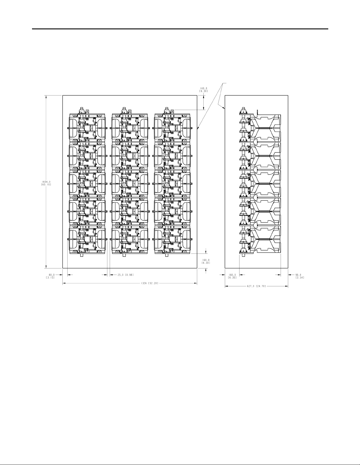
Typical Mounting Arrangement, 10…12 kV PowerBrick System
Figure 3 - Typical PowerBrick arrangement for 10…12 kV
Rockwell Automation Publication 7703E-IN001E-EN-P - July 2014 15
Page 16
Chapter 3 PowerBrick™ Installation
Front View
Typical spacing to ground metallic enclosure
components. Spacing may be reduced through the
full use of suitable insulation systems.
Side View
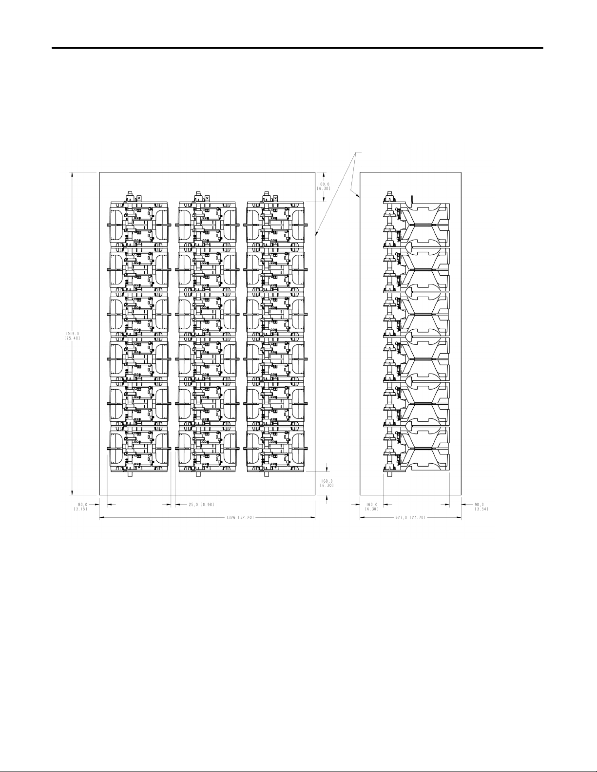
Typical Mounting
Arrangement,
12.1…14.4 kV
PowerBrick System
Figure 4 - Typical PowerBrick arrangement for 12.1…14.4 kV
16 Rockwell Automation Publication 7703E-IN001E-EN-P - July 2014
Page 17

PowerBrick™ Installation Chapter 3
IMPORTANT
Power Connections
ATT EN TI ON : To avoid shock hazard, lock out incoming power to power cables
when completing connections. Failure to do so may result in severe burns,
injury or death.
It is the responsibility of the OEM to ensure that suitable line and load cables
are used to satisfy the requirements of the equipment and meet local electrical
codes.
1. The PowerBrick units are connected to each other in order to create a
complete phase assembly. The flexible connector on the top of each
PowerBrick is attached to the fixed connector on the bottom of the
PowerBrick above.
2. The top PowerBrick should be connected to a suitable fixed terminal
location. Use appropriate cable lugs to attach suitable line cables to the line
cable terminal. Each PowerBrick can use M10 (3/8 in.) hardware. Refer to
Figure 5
specifications shown in Tab l e 4
3. Use cable lugs to attach suitable load cables to the load cable terminal
(lower). Refer to Figure 5
hardware to the specifications shown in Ta b l e 4
for the terminal location. Torque the fastening hardware to the
.
for the terminal location. Torque the fastening
.
4. Refer to Chapter 5
determine the required connections. Appendix B
schematic for a complete soft starter unit.
and Chapter 6 for a typical wiring diagram to
includes a typical
Rockwell Automation Publication 7703E-IN001E-EN-P - July 2014 17
Page 18
Chapter 3 PowerBrick™ Installation
Non-conductive mounting plate
(supplied by OEM)
Insulator
(supplied by OEM)
Flexible bus link
11 mm clearance hole
for M10 hardware
(supplied)
OEM provided
flexible link
Ter m i na l
Figure 5 - Typical Single Phase 15 kV PowerBrick Assembly (side view)
18 Rockwell Automation Publication 7703E-IN001E-EN-P - July 2014
Page 19

PowerBrick™ Installation Chapter 3
Figure 6 - Photo of Typical Single Phase PowerBrick Assembly (Front View)
Rockwell Automation Publication 7703E-IN001E-EN-P - July 2014 19
Page 20

Chapter 3 PowerBrick™ Installation
Grounding
PowerBrick Operating Restrictions
ATT EN TI ON : It is the responsibility of the OEM to ensure that the final enclosure
is suitably bonded to ground, and that provisions for grounding are made
according to local electrical codes and standards.
The SCRs in the power stacks are not intended for continuous operation.
Observe the following operating restrictions for the SMC when operating at the
thermal capacity limit and maximum ambient (40 °C). (Refer to Ta b l e 3
• Power stacks must be bypassed using a separate contactor or circuit breaker
when the motor is up to speed.
• Do not operate the power stacks for more than 60 seconds in one hour.
• Do not exceed 30 seconds for any individual duty cycle of the power
stacks.
• Do not operate the power stacks for at least five minutes between a start or
a stop cycle.
• For repeated hourly operation, forced ventilation is required.
Note: It may be possible to exceed some of the above restrictions if all maximum
ratings are not attained. For example, higher ambient conditions can be
supported when the % FLC and/or start time are reduced. Please consult factory
for details.
.)
ATT EN TI ON : The operating restrictions for the SMC must be adhered to. Failure
to observe the recommended precautions may result in injury to personnel or
damage to the equipment.
20 Rockwell Automation Publication 7703E-IN001E-EN-P - July 2014
Page 21

PowerBrick™ Installation Chapter 3
8.9 [0.35]
4 holes
Includes features to secure
HV wire for maintained spacings.
Approximate dimensions in mm [inches]
IMPORTANT
Voltage Sensing Board Dimensions
Figure 7 - Voltage Sensing Board Dimension Diagram
Mounting and Connecting the Voltage Sensing Board
The voltage sensing board (VSB) for the relevant voltage range (see table below)
should be mounted adjacent to the PowerBrick (refer to Figure 7
for
dimensions). All connection points are to be made accessible.
Description Line Voltage
Voltage Sensing Board
(3 phase, 50/60 Hz)
10,000…12,000V 126 7703E-VSM
12,001…14,400V 97 7703E-VSN
MV Ratio Catalog Number
Connect the voltage sensing board to the L1 to L3 (Line) and T1 to T3 (Load)
terminals of the power stack (refer to Figure 8
Recommended specifications for wire used on medium voltage connections: UL
style 3239, #18 AWG, 40 KVDC silicone rubber insulated wire, covered with
and Chapter 6).
PCV tubing or other suitable material.
The wires must be prevented from touching live or grounded metals, and low
voltage wiring, or have supplemental insulation suitable for the application.
Use the tapered features below the Lx and Tx terminals to maintain wire
spacings in this area.
Rockwell Automation Publication 7703E-IN001E-EN-P - July 2014 21
Page 22

Chapter 3 PowerBrick™ Installation
To Interface Board
Ground Connections
The MV ratios shown above are nominal values and may be fine tuned to achieve
better accuracy on the display of the SMC Flex control module. While running
the motor in bypass mode, compare the voltage displayed on the control module
to a known accurate meter connected to the same source voltage as the motor the
MV SMC Flex is controlling. Parameter 106, MV Ratio, may be changed up or
down to match the Flex display to the external meter. A small change in ratio can
make a large change in the display, so 5 units at a time are recommended.
Increasing the ratio will decrease the displayed voltage, and visa versa.
Figure 8 - Voltage Sensing Board
22 Rockwell Automation Publication 7703E-IN001E-EN-P - July 2014
Page 23

PowerBrick™ Installation Chapter 3
Current Loop Gate Drive Power Assembly (CLGD)
The CLGD power assembly is provided as a loose component with the
PowerBricks. It should be mounted adjacent to the PowerBrick in a manner that
allows the secondary cable assembly to be correctly installed (see below).
The CLGD power assembly consists of three parts:
1. Power supply (transformer with secondary terminal blocks and sensing
CT)
2. Current Transformer (CT) assembly (plastic tubing with two current
transformers per PowerBrick)
3. Loop Cable (white, silicone insulated, 50 kV DC, #6 AWG)
The CT assembly is mounted with hardware to the left side of the PowerBrick
stack, and can be pivoted to the left by loosening the mounting hardware to allow
removal of individual PowerBricks without removing the CT assembly. The
current transformer secondary leads plug into the gate driver board directly
behind each CT, and must all be unplugged to pivot the assembly.
Figure 9 - PowerBrick Current Loop Gate Drive Cable Assembly and Power Supply
ATT EN TI ON : Check that all CT leads are plugged into each gate driver board
before putting the SMC into service. Failure to do so may result in erratic
operation and/or equipment damage during option stop maneuvers.
Rockwell Automation Publication 7703E-IN001E-EN-P - July 2014 23
Page 24

Chapter 3 PowerBrick™ Installation
CLGD CT
Conne ction
Ter m in a l
CLGD CTs
CLGD CT
Connect ion
Terminal
Figure 10 - Connection of CLGD CTs to Gate Driver Board
The CT assembly has a loop cable which passes through the tube and connects to
terminal blocks above and/or below the assembly (depending on how the
assembly is implemented). The three phases of loop cables are connected in series
and to the secondary of the power supply transformer. The transformer rating
and secondary voltage are selected to provide 40 or 50 amps in the loop cable.
See Ta b l e 5
See Appendix C
Table 5 - Matching Loop Length to Power Supply Transformer Rating
Power Supply Transformer Rating Total Loop Length for #6 AWG Cable
50 VA, 115/230:0.6V 21 feet ± 4 in. (6.4 m ± 10 cm)
100 VA, 115/230:1.5V 50 feet ± 8 in. (15.2 m ± 20 cm)
(1) The 50-foot length is 3 x 14 ft HV wire plus 8 ft LV wire.
for matching the loop length to the power supply transformer rating.
for part numbers.
(1)
ATT EN TI ON : The loop cable length must be as specified above. The loop cable is
the load for the transformer and establishes the loop current. If it is not correct,
a longer length will not provide sufficient power to the gate driver boards, and a
shorter length will overload the cable or transformer.
24 Rockwell Automation Publication 7703E-IN001E-EN-P - July 2014
Page 25

PowerBrick™ Installation Chapter 3
To
control
power
1. Power Supply
2. Current Transformer Assembly
3. Loop Cable
4. Terminal
5. Return Cable #6 AWG (13 mm²)
The total length of the three loop
cables and the return cable must be
50 feet ± 8 in.
(152. m ± 20 cm).
PowerBrick
assemblies
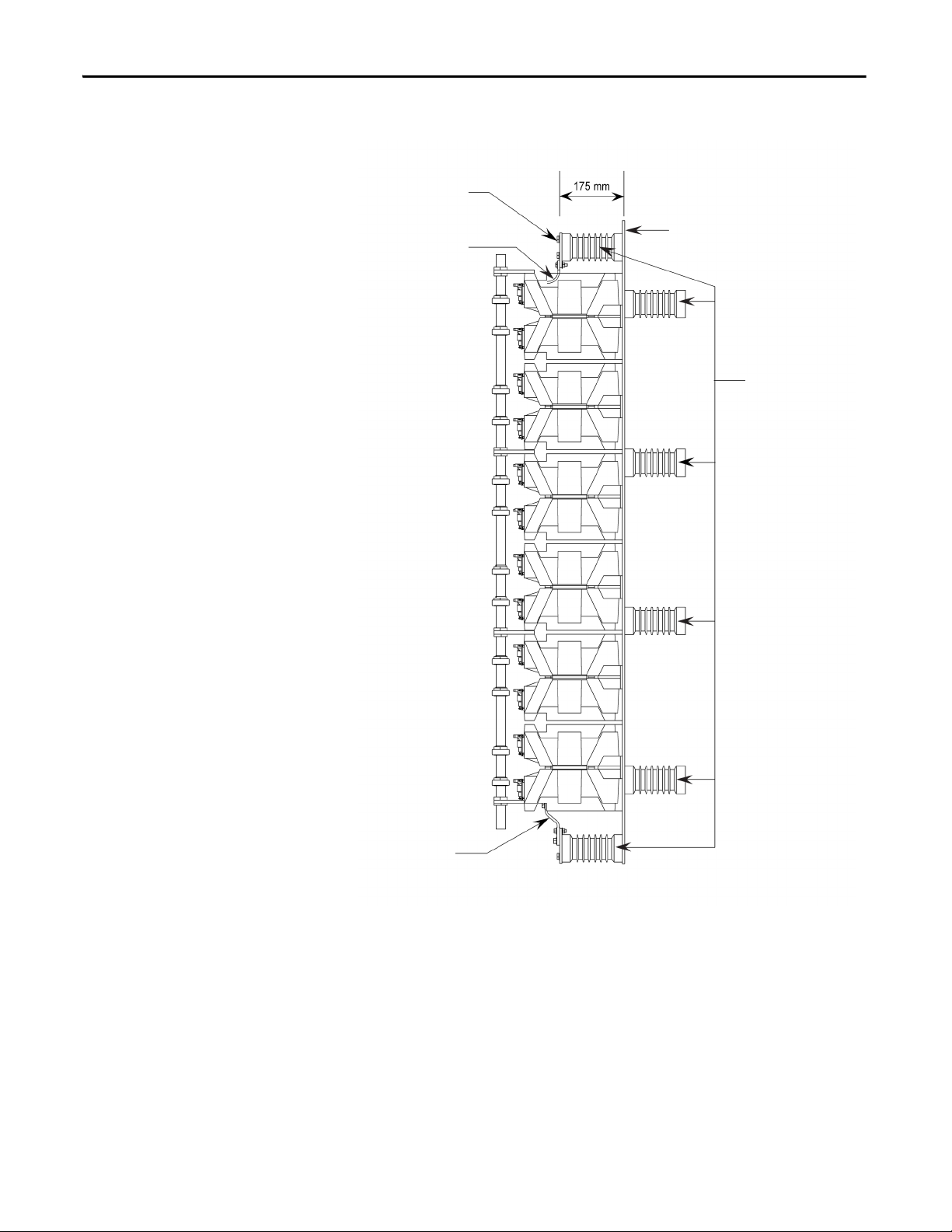
NOTE:
A sensing CT is supplied to monitor the current in the loop. It provides a signal
to the Interface Board to inform the SMC Flex control module that the power
supply is operating. If the current loop is not operating, option stop maneuvers
will be inhibited. An Alarm will be generated in the SMC Flex control module if
the signal is lost after control power has been applied. If control power is applied
without the signal, the controller will not provide option stop maneuvers until
the module is powered up with the signal present.
Figure 11 - Typical 12 kV Implementation for Current Loop
Rockwell Automation Publication 7703E-IN001E-EN-P - July 2014 25
Page 26

Chapter 3 PowerBrick™ Installation
1. Power Supply
2. Current Transformer Assembly
3. Loop Cable
4. Terminal
5. Return Cable #6 AWG (13 mm²)
The total length of the three loop
cables and the return cable must be
50 feet ± 8 in.
(152. m ± 20 cm).
PowerBrick
assemblies
NOTE:
Figure 12 - Typical 15 kV Implementation for Current Loop
26 Rockwell Automation Publication 7703E-IN001E-EN-P - July 2014
Page 27

Control Component Installation
Top mounting holes
for SMC Flex
Control Module
Front View
Side View
Mounting holes (4)
7.14 mm [0.281 in.] dia.
Bottom mounting holes for
SMC Flex Control Module
Approximate dimensions in mm [inches]
Chapter 4
Interface Board Installation
Mount the 7703E-INTB Interface Board in a suitable location within a low
voltage compartment, using the appropriate hardware. Use the interface board
mounting bracket (refer to Figure 13
).
ATT EN TI ON : Do not mount the interface board in the same compartment as
high voltage components. Ensure that barriers are provided in the final
application to prevent access to any live high-voltage parts, including insulated
conductors located in enclosures with low voltage parts and wiring. Failure to
do so may result in severe burns, injury or death.
Figure 13 - Mounting the Interface Board
Rockwell Automation Publication 7703E-IN001E-EN-P - July 2014 27
Page 28

Chapter 4 Control Component Installation
Phase A
Fiber Optic Transmitter
sends gate signals
to multiplexer
Phase B
Fiber Optic Transmitter
Phase C
Fiber Optic Transmitter
SW3: Used to
defeat temperature
feedback channels
Temperature Feedback
Fiber Optic Receivers
SW2: When ON (up), provides
test pulses to gate driver circuits.
Must be OFF (down)
for normal operation
LED (Red) ON
when test pulses on
LED (Yellow) ON
when Phase A
gate signal active
LED (Yellow) ON
when Phase B
gate signal active
LED (Yellow) ON
when Phase C
gate signal active
TP4: Phase A
gate signal
TP11: Phase B
gate signal
TP13: Phase C
gate signal
TP15: Common for
Gate/Pulse TPs
TP8: Common for
Gate/Pulse TPs
LEDs (Green): ON when
signal present at temperature
feedback fiber optic receivers
Ribbon connec tors to connect to
SMC Flex Control Module
(underneath control module)
SMC Flex Control Module
Current feedback
test points
Ribbon connector
to Voltage
Sensing Board
Current loop
power supply
sensor input
TB5: Current
Tra ns fo rm er
Conne ctions
TP18, 19, 20:
Power Sup ply
test points
Replacement
Part Number
1. ICOM is the common connection for Gate and Pulse test points.
2. VCOM is the common connection for Current and Voltage feedback test points.
Do not connect to earth ground. Do not connect ICOM and VCOM together,
either directly or through test probes, meter or scope common.
Notes:
Control Power
110…240V AC
Power out
to SMC Flex
Serial
Number
Voltage feedback
test points
Module common:
No connection
LED (Green): ON
when current loop
power supply
is present
LED (Green): ON
when power is present
ATT EN TI ON : Do not touch or bend the connectors on the Interface Board when
handling it. Damage to the connectors may result in loss of communication
signals from the MV SMC Flex to other components.
Figure 14 - Interface Board Layout
28 Rockwell Automation Publication 7703E-IN001E-EN-P - July 2014
Page 29

Control Component Installation Chapter 4
IMPORTANT
10…12 kV and 12.1…15 kV
Two fiber optic devices per phase are used. One connects to the temperature
feedback in the upper PowerBrick, and the other connects to the fiber optic
multiplexer board (see below).
Interface Board Connections
SMC Flex Control Module
Connect control power to the interface board. Use a grounded supply source
from 110…240 +10, -15% VAC, 50/60 Hz, 15 VA.
Connect 5A current transformer (CT) secondary signals to the interface board,
noting the required CT polarity. Three-phase CTs are required.
WARNING: Do not connect to Interface Board Vcom terminal.
1. Connect the ribbon cables (5) to the back of the SMC Flex control
module.
2. Align the ribbon cables (5) from the SMC Flex Control Module with the
connectors on the Interface Board. Push the ribbon connectors into the
mating connectors on the interface board.
3. Use the supplied screws to securely fasten the module to the board
mounting bracket.
4. Supply power to the SMC Flex control module and make the required
control connections.
EMC Compliance
Please refer to User Manual, MV SMC Flex Motor Controller Bulletins 1503E,
1560E and 1562E – Publication 1560E-UM051_-EN-P
on wiring and programming the unit.
ATT EN TI ON : This product has been designed for Class A equipment. Use of the
product in domestic environments may cause radio interference, in which case,
the installer may need to employ additional mitigation methods.
The following guidelines are provided for EMC installation compliance.
for detailed instructions
Enclosure
Install the product in a grounded metal enclosure.
Rockwell Automation Publication 7703E-IN001E-EN-P - July 2014 29
Page 30

Chapter 4 Control Component Installation
Wiring
Wire in an industrial control application can be divided into three groups: power,
control, and signal. The following recommendations for physical separation
between these groups are provided to reduce the coupling effect.
• Different wire groups should cross at 90° inside an enclosure.
• Minimum spacing between different wire groups in the same tray should
be 16 cm (6 in.).
• Wire runs outside an enclosure should be run in conduit or have shielding/
armor with equivalent attenuation.
• Different wire groups should be run in separate conduits.
• Minimum spacing between conduits containing different wire groups
should be 8 cm (3 in.).
• For additional guidelines, please refer to Wiring and Ground guidelines,
publication DRIVES-IN001M-EN-P
• Wire earth ground to control terminal 14 of the SMC Flex control
module.
• Use shielded wire for:
• PTC Input
• Tac h In pu t
• Ground Fault Input
• Terminate shield wires to terminal 14.
• Ground fault CT must be inside or within 3 m of metal enclosure.
• To meet product susceptibility requirements, ferrite cores need to be
added to the communication lines. All cores specified below are split core
type, so they can be added to existing connections.
• When using an external HIM (or DPI interface), a core should be
added to the HIM cable near the SMC Flex control module. The
recommended core is Fair-Rite no. 0431167281 or equivalent.
• When using DeviceNet, two cores need to be added to the DeviceNet
cable near the SMC Flex control module. The recommended cores are
TDK ZCAT2033 0930H and TDK ZCAT2035 0930 or equivalent.
.
Control Power
30 Rockwell Automation Publication 7703E-IN001E-EN-P - July 2014
Control Voltage
The SMC Flex controller will accept a control power input of 100…240V AC,
(-15 / +10%), 1 phase, 50/60 Hz. Refer to the product nameplate to verify the
control power input voltage.
Connect control power to the controller at terminals 11 and 12. The control
power requirement for the control module is 75 VA. Depending on the specific
application, additional control circuit transformer VA capacity may be required.
Page 31

Control Component Installation Chapter 4
Control Wiring
Ta b l e 6 provides the control terminal wire capacity and the tightening torque
requirements. Each control terminal will accept a maximum of two wires.
Table 6 - Control Wiring and Tightening Torque
Wire Size Torque
0.75…2.5 mm
2
(#18…#14 AWG) 0.6 N•m (5 lb•in.)
Control Terminal Designations
As shown in Figure 15, the SMC Flex controller contains 24 control terminals on
the front of the controller.
Figure 15 - SMC Flex Controller Control Terminals
Rockwell Automation Publication 7703E-IN001E-EN-P - July 2014 31
Page 32

Chapter 4 Control Component Installation
Table 7 - Terminal Descriptions
Terminal Number Description Terminal Number Description
11 Control Power Input C 23 PTC Input
12 Control Power Co mmon C 24 PTC Input
13 Control Enable Input
14 Control Module Ground 26 Tach Input ( + )
15 Option Input #2 27 Ground Fault Transformer Input
16 Option Input #1 28 Ground Fault Transformer Input
17 Start Input 29 Aux. Contact #2
18 Stop Input 30 Aux. Contact #2
19 Aux. Contact #1 (Ext. Bypass)
20 Aux. Contact #1 (Ext. Bypass) 32 Aux. Contact #3
21 Not Used 33 Aux. Contact #4 (Normal)
22 Not Used 34 Aux. Contact #4 (Normal)
(1) Do not connect any additional loads to these terminals. These “parasitic” loads may cause problems with operation, which may result in false starting and stopping.
(2) Aux. Contact #1 is always programmed for Ext. Bypass (N.O.) to control the bypass contactor in MV applications.
(3) Aux. Contact #4 is always programmed for “Normal” (N.O.) to control the isolation contactor in MV applications.
(4) RC snubbers are required on inductive loads connected to auxiliary.
(1)
(2)
25 Tach Input ( - )
31 Aux. Contact #3
(3) (4)
Connecting Interface Board to Voltage Sensing Board
Note: The OFF state leakage current for a solid-state device connected to an
SMC Flex input must be less than 6 mA.
Use the wire harness provided to connect the Voltage Sensing Board and the
Interface Board. Refer to Figure 14
interface board, and Figure 8 on page 22
for the location of the connector on the
for the connector on the voltage sensing
board.
32 Rockwell Automation Publication 7703E-IN001E-EN-P - July 2014
Page 33

Control Component Installation Chapter 4
Phase gate drive
fiber optic signals
(from Interface Board)
To G ate D ri ver Bo ard s
4.0 [0.16]
(5) MTG holes
Phase A
Phase B
Phase C
Connecting Fiber Optic Multiplexer Board to Gate Driver Board
The 7703E-MUXB Fiber Optic Multiplexer board accepts fiber gate drive signals
from the interface board (7703E-INTB) and splits them into the required fiber
optic gate drive signals for 10…15 kV.
Figure 16 - Fiber Optic Multiplexer Board
Figure 17 - Fiber Optic Multiplexer Board Dimensions and Connections
Rockwell Automation Publication 7703E-IN001E-EN-P - July 2014 33
Page 34

Chapter 4 Control Component Installation
IMPORTANT
IMPORTANT
Table 8 - Fiber Optic Multiplexer Board Specifications
Control Voltage 110/120V…220/240V at 50/60 Hz, 30 VA
Gate Drive (In/Out) Via Fiber Optics
1. Use the fiber optic cables (Cat. No. 7703E-XXFOXX) to connect each
fiber optic receiver from the gate driver boards to the fiber optic
multiplexer board (refer to Figure 16
driver boards of each power phase are connected to the correct terminals
on the fiber optic multiplexer board. Observe the minimum bend radius of
at least 45 mm (1.75 in.) for the fiber optic cables.
ATT EN TI ON : Do not sharply bend or strike the fiber optic cables when handling
them. A minimum bend radius of at least 45 mm (1.75 in.) should be
maintained throughout the system. Damaging the cables may result in signal
loss to the components and improper functioning of the unit.
Fiber optic components are color coded for easier connections. Receiver
terminals are dark blue, and transmitter terminals are grey or black. The cables
have a grey connector at one end and a blue one at the other. When connecting
to the gate driver boards, the dark blue connector must plug into the dark blue
receiver and the grey connector must plug into the grey or black transmitter.
and Figure 17). Ensure that the gate
Additional Control Components
Refer to the appropriate wiring diagram in Chapter 6
It is acceptable to connect the fiber optic transmitter cables to any port within
a particular power phase. Note that the cables for the temperature feedback
ports should be connected to the correct phase. Refer to Figure 14
Interface Board layout.
2. Connect a single fiber optic cable between the interface board transmitter
(one per phase) to the corresponding receiver on the fiber optic
multiplexer board.
3. Connect the temperature feedback fiber optic receivers for each phase
from the interface board to the appropriate gate driver board transmitter.
Refer to Chapter 6
feedback fiber optic connections.
Additional control components are required to complete the circuit, depending
on the application. Some of these control components are outlined in Chapter 5
and Appendix B
It is the responsibility of the OEM to ensure that all required power and control
components are supplied and functional.
.
for the appropriate diagram for the temperature
.
for the
34 Rockwell Automation Publication 7703E-IN001E-EN-P - July 2014
Page 35

Chapter 5
Main and Bypass Switching Device Installation
Introduction
Main Contactor or Circuit Breaker
Bypass Contactor or Circuit Breaker
The MV SMC components are designed for intermittent starting duty. A bypass
contactor or circuit breaker must be used to bypass the PowerBrick assemblies
once the motor is at full speed.
A line switch is required in order to isolate the power stacks from line voltage.
• If a line contactor is used, suitable short-circuit protection must be
provided in compliance with relevant standards and/or local codes (refer
to Section 2).
• If a circuit breaker is used for the line switch, it must be rated to handle
normal load and short-circuit conditions.
A bypass contactor or circuit breaker must be used in the SMC configuration to
bypass the SCRs once the motor is up to speed. The bypass must have an opening
time of 100 ms or less.
ATT EN TI ON : A bypass contactor or circuit breaker must be installed to
complete the SMC configuration. SCRs are not rated for continuous duty. The
duty cycle is limited to 60 seconds per hour. This can be a combination of
starting and stopping cycles that does not exceed 30 seconds per cycle. Failure
to install a bypass contactor or circuit breaker may result in damage to
components from overheating.
Rockwell Automation Publication 7703E-IN001E-EN-P - July 2014 35
Page 36

Chapter 5 Main and Bypass Switching Device Installation
Notes:
36 Rockwell Automation Publication 7703E-IN001E-EN-P - July 2014
Page 37

Typical Wiring Diagrams
Chapter 6
Wiring Diagrams
The following wiring diagrams illustrate the connections between the main
components of the MV SMC OEM components.
Additional components are typically required to complete the MV SMC. Refer
to Appendix B
implemented to form a complete solution.
for examples of how these additional components can be
ATT EN TI ON : Wires used for connecting the components must be sufficiently
insulated to withstand system voltage. Refer to the appropriate wiring diagram
for the wire insulation requirements. Failure to use adequately insulated wiring
may cause injury to personnel and/or damage to the equipment.
Rockwell Automation Publication 7703E-IN001E-EN-P - July 2014 37
Page 38

Chapter 6 Typ ica l Wir ing Diagr ams
NOTE: Only devices supplied by Rockwell Automation are shown.
Additional devices are required to form a complete solution
(refer to Appendix B
for a typical schematic showing other
devices).
CONNECTIONS SHOWN FOR PHASE A
WIRE CONNECTIONS FOR PHASE B
WIRE CONNECTIONS SHOWN FOR PHASE C
DON’T CONNECT
USED ONLY FOR 4 OR MORE POWERBRICKS IN SERIES
SEE CHAPTER 3, Current Loop Gate Drive Power Assembly
(CLGD) on page 23, FOR CABLE REQUIREMENTS
LEGEND
NUMBER OF
POWERBRICKS (n)
VOLTAGE
VOLTAGE
SENSING
BOARD
TO LINE AND LOAD TERMINALS
TO INTE RFACE BOAR D
FIBER
OPTIC
CABLES
LINE
POWERBRICK 1
THERMISTOR
POWERBRICK n
LOAD
PHASE B
PHASE C
CURRENT LOOP CT
CURRENT LOOP
TRANSFORMER
GATE TRANSMITTERS
SMC FIBER OPTICS
MULTIPLEXER
BOARD
SMC INTERFACE BOARD
SMCFLEXIB
SMC INTERFACE BOARD
SMCFLEXIB
GATE TRANSMITTERS
TO SMC FLEX MODULE
Figure 18 - Typical Power Circuit Wiring Diagram (10-15 kV)
38 Rockwell Automation Publication 7703E-IN001E-EN-P - July 2014
Page 39

Final Test Procedures
Chapter 7
Final Test Procedures
• Verify that the enclosure is properly grounded.
• Verify that phase-to-phase and phase-to-ground clearances meet the
requirements of the local electrical code.
• Visually check for sufficient electrical clearances, creepage allowances and
bend radii. Refer to the applicable local electrical codes.
• Check the tightness of all power and control connections. Refer to Ta b l e 4
on page 13 for recommended torque values. Gently tug on all wires to
ensure that they are properly connected.
ATT EN TI ON : All hardware for electrical connections must be torqued to the
above specifications. Failure to do so may result in electrical faults causing
personal injury or damage to the equipment.
• Check for cross-threaded hardware. In addition to the regular power
connections, check the connections and wiring to the voltage sensing
board.
• The high voltage silicone-insulated wires must be identified with tube
markers. Avoid routing the wires over any components. If the wires are
routed near live parts or ground, there must be enough slack in the wire to
allow at least 15 cm (6 in.) of creep or clearance between the wire and
other parts. Tie wraps must not tightly squeeze the high voltage wires, and
must not be put on with a tie-wrap gun.
• Do not remove the plastic plugs from unused fiber optic transmitters on
the circuit boards.
• Verify that the fiber optic cables between the interface board, fiber optic
multiplexer board, and the gate driver boards are connected to the correct
power phase.
• Check the routing of the twisted pair of red and white cathode and gate
wires from the SCRs. They can safely touch the heatsink on the side of the
SCR that they are exiting; however, they must not touch the heatsink on
the other side of the SCR. The wires must be properly supported to ensure
this condition is met. See wiring diagrams in Appendix B
sequences.
• Wiring to the voltage sensing board from the power stacks must be rated
for the line voltage. Rockwell Automation recommends UL style 3239,
#18 AWG, 40 kV DC silicone rubber insulated wire covered with PVC
tubing or other suitable material for this application. These wires must not
touch live parts, grounded metal or low voltage wiring.
for the
Rockwell Automation Publication 7703E-IN001E-EN-P - July 2014 39
Page 40

Chapter 7 Final Test Procedures
Jumper
• The bypass vacuum contactor or breaker (and capacitor contactor if
applicable) must have a fast drop-out time (typically 100 milliseconds or
less).
Dielectric Test
1. Remove the ribbon cable and ground wires from the voltage sensing board,
and isolate the ends to prepare for the Hi-Pot test.
2. Jumper the line and load terminals together within each phase as shown in
Figure 19
Figure 19 - Example of Jumper Positioning for Hi-pot Test
.
3. Measure the resistance between the line and load sides of each PowerBrick
phase assembly to make sure there is zero resistance. This indicates that the
jumpers are properly set.
4. Perform a Hi-Pot test as required by the applicable local codes and
standards. Typical levels for field testing are two times the rated voltage of
the equipment.
5. After the Hi-Pot remove the heatsink jumpers. Re-connect the feedback
board wires.
6. Perform a resistance check for each SCR. The SCR resistance can be
checked directly at the device or at the leads on the gate driver board.
a. The gate-to-cathode resistance should range from 10…40 ohms for all
styles.
b. The cathode-to-cathode resistance can also be checked and should be
between 20…32 ks per brick.
40 Rockwell Automation Publication 7703E-IN001E-EN-P - July 2014
Page 41

Final Test Procedures Chapter 7
IMPORTANT
7. Check all line and load resistances to ground at the interface board voltage
feedback test points. The measurement for all voltages should be within
11…13 kΩ.
Additional Tests
Programming
Perform additional tests, as outlined in Chapter 3 of User Manual, MV SMC Flex
Motor Controller, Bulletins 1503E, 1560E and 1562E, Publication
1560E-UM051_-EN-P
.
MV SMC Flex Module
Refer to Chapter 4
The default (factory) parameter settings are as shown in Appendix B
If the factory settings are not suitable for the application, program the module to
meet the application requirements.
(1)
for programming procedures.
(1)
.
The module should be programmed with an understanding of how the SMC
functions, and the characteristics of the motor and driven load. Inappropriate
settings may elicit unexpected results such as lack of acceleration torque or
full-voltage starting. For Pump Control applications, refer to Application
(1)
Considerations in publication 1560E-UM051_-EN-P
.
Voltage Sensing Module
The MV ratios shown above are nominal values and may be fine tuned to achieve
better accuracy on the display of the SMC Flex control module. While running
the motor in bypass mode, compare the voltage displayed on the control module
to a known accurate meter connected to the same source voltage as the motor the
MV SMC Flex is controlling. Parameter 106, MV Ratio, may be changed up or
down to match the Flex display to the external meter. A small change in ratio can
make a large change in the display, so 5 units at a time are recommended.
Increasing the ratio will decrease the displayed voltage, and visa versa.
Table 9 - MV Ratio
Voltage MV Ra tio
12000V 126
14400V 97
(1) References apply to publication 1560E-UM051_-EN-P.
Rockwell Automation Publication 7703E-IN001E-EN-P - July 2014 41
Page 42

Chapter 7 Final Test Procedures
SW2 – Close (slide up) to initiate test pulse
Red LED – ON when test pulses active
Power Supply Test
ATT EN TI ON : Servicing energized industrial control equipment can be
hazardous. Severe injury or death can result from electrical shock, burn, or
unintended actuation of controlled equipment. Before proceeding, ensure that
all sources of power are isolated and locked out. Verify that all circuits are
voltage free using a hot stick or appropriate voltage measuring device. Any
covers or barriers removed during this procedure must be replaced and securely
fastened before energizing equipment. Where appropriate, the case of test
equipment should be connected to ground.
1. Isolate incoming power
2. Open the door(s) providing access to the SCR/heatsink assemblies. You
will be touching components which are connected to the high voltage
power circuit, so be sure to isolate power as stated above.
3. Apply rated control voltage to the control circuits from a separate control
source, or by plugging into the test source connector, and selecting the
TEST position of the control switch.
4. Check voltage on each gate-driver board by connecting a DC voltmeter at
TP4(+) and TP3(-). (See Figure 21
.) The voltage should be
18…22V DC.
5. Locate the SMC Flex Interface board in the control section (See
Figure 20
). This circuit board has the control module mounted on it.
Locate the switch labeled SW2 at the upper left corner of the board. Close
the switch by sliding the toggle up. This starts a pulse generator to supply
simulated gate-pulse signals via fiber optic cables to the gate driver boards.
A red LED beside the switch, and the three yellow LEDs on the left side of
the Interface board should be lit.
Note: They may appear dim, depending on ambient light conditions.
Figure 20 - Interface PCB
42 Rockwell Automation Publication 7703E-IN001E-EN-P - July 2014
Page 43

Final Test Procedures Chapter 7
Tem pera tur e si gn al
fiber optic transmitter
Yel lo w LE D
Thermis tor
connector
Gate signal
test point
Gate/cathode
connector
Overvoltage +20V test point
+5V test point
Gate signal
fiber optic receiver
Plug-in test power
supply
Current loop
CT connector
Snubber
terminal
Cathode
terminal
Common
test point
6. With the gate pulses on, check the voltage again on each gate-driver board
as described in step 4
above. The voltage should be 4…5V DC.
7. Locate the Portable Test Power Supply that was included with the
equipment, and verify that the rating corresponds to the available power
system (i.e., 110/120V AC or 220/240V AC). Plug the unit into the
power source, and plug the green connector into J1 on each of the gate
driver boards (see Figure 21
Figure 21 - Test Power Application on Gate Driver Board
).
8. The yellow LED on the upper right-hand side of the energized gate driver
circuit should be lit (it may appear dim, depending on ambient light
conditions). While the gate pulses are still on, check the voltage on each
gate driver board as described in step 4
above. The voltage should be
10…12V DC. If the voltage is less than 5V, then you have a bad gate drive
board. Do not leave the Portable Test Power Supply connected to a bad
gate driver board. The power supply adapter will burn up if the gate driver
board is shorted.
9. A more detailed check is performed by verifying the actual gate pulses by
connecting an oscilloscope between TP1 and TP3 (-) (see Figure 4 on
page 16). To check gate pulses, the pulse generator must be enabled
(i.e. SW2 toggled up) and the Portable Test Power Supply should be
connected to J1. The pulse should appear as shown in Figure 22
Figure 23
.
and
Rockwell Automation Publication 7703E-IN001E-EN-P - July 2014 43
Page 44

Chapter 7 Final Test Procedures
Microseconds
Vol ts
Microseconds
Figure 22 - Gate Pulse Detail – Typical SCR (ABB)
Figure 23 - Gate Pulse Test Waveform
10. If no pulse is observed, and the yellow LED is lit, check for a shorted gate
on the SCR by removing the green plug and connecting an ohmmeter to
the gate leads. If the LED is not lit, and the circuit voltage is as specified in
(above), pinch the tab on the blue fiber-optic connector and
step 8
carefully pull it straight out of the receiver. The end of the connector
should glow red to indicate the presence of a gate signal.
ATT EN TI ON : Do not look directly into the end of the fiber optic cable.
If it does not, remove the other end of the cable from the interface board
and check that the grey transmitter is emitting red light. If it is, the fiberoptic cable must be replaced. If it isn’t, the interface board should be
replaced.
44 Rockwell Automation Publication 7703E-IN001E-EN-P - July 2014
Page 45

Final Test Procedures Chapter 7
11. When each gate driver circuit has been checked, disconnect the power
supply and remove it from the cabinet.
ATT EN TI ON : The gate-drive circuits operate at high voltage when the SMC is
energized. Failure to remove the portable test power supply will result in
equipment damage and may cause severe injury or death.
12. Open the switch SW2 on the interface board (see Figure 21
) before
returning the unit to service. Ensure the red LED is off.
ATT EN TI ON : If the SW2 switch is not in the open position when the SMC is
energized, the motor will start in an uncontrolled manner and may cause severe
damage.
13. 13.Check that all plugs and connectors are secure. Retrieve all hardware
and tools from the equipment. Replace and secure any barriers removed
during servicing and close all doors before applying power.
ATT EN TI ON : Servicing energized industrial control equipment can be
hazardous. Severe injury or death can result from electrical shock, burn, or
unintended actuation of controlled equipment. Recommended practice is to
disconnect and lock out control equipment from power sources, and allow any
stored energy in capacitors to dissipate. The safety related work practices of
NFPA 70E, Electrical Safety Requirements for Employee Workplaces, must be
followed if it is necessary to work in the vicinity of energized equipment.
1. Apply rated control voltage to the control circuit.
2. Using the control schematic, apply control signals to cause relays and
contactors to energize, to verify operation.
3. Remove any jumpers used in the test and restore all circuits to normal
when finished.
Rockwell Automation Publication 7703E-IN001E-EN-P - July 2014 45
Page 46

Chapter 7 Final Test Procedures
Start-Up
Spare Parts
1. Remove any temporary jumpers or grounding devices used during
commissioning.
2. Check that all tools are removed from the equipment. Any tools or
hardware used or dropped during installation and commissioning must be
retrieved and accounted for.
3. Check that all barriers or covers removed during installation or
commissioning have been securely mounted.
4. Close and secure all doors, and verify function of all interlocks that
prevent access to medium voltage compartments when the unit is
energized.
5. The controller is ready to power the motor.
For a complete listing of spare parts, refer to Appendix C.
46 Rockwell Automation Publication 7703E-IN001E-EN-P - July 2014
Page 47

Component Deratings
Appendix A
Deratings Specifications
The components described in this publication may be applied in a wide variety of
situations. Some applications may require component derating. For example, at
altitudes above 1000 m (3300 ft), the maximum current and basic impulse level
(BIL) are reduced as shown in Ta b l e 1 0
Table 10 - Component Derating Table
Altitude Rating
0…1000 m
(0…3300 ft)
1001…2000 m
(3301…6600 ft)
2001…3000 m
(6601…9900 ft)
3001…4000 m
(9901…13,200 ft)
4001…5000 m
(13,201…16,500 ft)
Reduce Max. Continuous Current Rating by: B.I.L. Withstand Rating
160 A c 340 A 580 A 12 kV 15 kV
— — 75 kv 95 kV
5 A 10 A 15 A 66 kV 84 kV
10 A 20 A 30 A 59 kV 74 kV
15 A 30 A 45 A 52 kV 66 kV
20 A 40 A 60 A 46 kV 58 kV
.
Rockwell Automation Publication 7703E-IN001E-EN-P - July 2014 47
Page 48

Appendix A Component Deratings
Notes:
48 Rockwell Automation Publication 7703E-IN001E-EN-P - July 2014
Page 49

Typical Schematic Diagrams
Appendix B
Introduction
This Appendix contains a typical schematic for a complete MV SMC Flex
controller (refer to Figure 24
Refer to publication 1560E-UM051_-EN-P
wiring configurations. The examples shown are not a recommendation for the
correct wiring configurations, nor is the OEM required to follow this design
exactly.
The OEM must ensure that all wiring for the unit meets all performance and
safety requirements, including any applicable laws, regulations, codes and
standards.
Rockwell Automation does not assume any responsibility or liability for loss or
damages caused by failures in the unit manufactured by the OEM.
For more information, see the Warranty section in General Terms and
Conditions of Sale, Publication 6500-CO001_-EN-P.
).
for additional samples of control
Rockwell Automation Publication 7703E-IN001E-EN-P - July 2014 49
Page 50

Appendix B Typical Schematic Diagrams
WIRE CONNECTIONS FOR PHASE A
WIRE CONNECTIONS FOR PHASE B
WIRE CONNECTIONS SHOWN FOR PHASE C
DON’T CONNECT
CURRENT LOOP CONDUCTORS PASS THROU GH THE CURRENT
LOOP GATE DRIVE CURRENT TRANSFORMER ASSEMBLY
REMOTE EQUIPMENT
USED ONLY FOR 4 OR MORE POWERBRICKS IN SERIES
NOT INCLUDED WITH MV SMC FLEX OEM KITS
SHORT CIRCUIT PROTECTIVE DEVICE (SCPD); MAY BE A CIRCUIT
BREAKER OR FUSED CONTRACTOR WITH DISCONNECT
LEGEND
NUMBER OF
POWERBRICKS (n)
VOLTAGE
MAXIMUM TWO STARTS PER HOUR WITH A MINIMUM OF FIVE
MINUTES BETWEEN STARTS
CAUTION:
FROM
CONTROL
CIRCUIT
SMC FLEX
FIRER OPTIC
BOARD
SMC FLEX INTERFACE BOARD
SMC FLEX XIE
GATE TRANSMITTERS
VOLTAGE FEEDBACK
VBS
FROM CLT
SHT 2, LINE C-212
CT INPUTS
FROM
CONTROL
CIRCUIT
TO SMC FLEX CONTROL MODULE
GATE TRANSMITTERS
POWERBRICK 1
POWERBRICK n
Figure 24 - Typical Power System Diagram (10-15 kV)
Note: Requires input disconnection (optional), as well as main and bypass
vacuum contactors.
50 Rockwell Automation Publication 7703E-IN001E-EN-P - July 2014
Page 51

CURRENT LOOP CONDUCTORS PASS THROUGH THE CURRENT
LOOP GATE DRIVE CURRENT TRANSFORMER ASSEMBLY
NOT INCLUDED WITH MV SMC FLEX OEM KITS
LEGEND
TO
SMCFLEXIB-TB6
FROM SMCFLEXIB
SMC FLEX CONTROL
TERMINALS
EXTERNAL BYPASS
SMCFLEXIB
FIBER OPTIC BOARD
SMC FLEX TO BE
PROGRAMMED BY
THE CUSTOMER
BEFORE START-JP
START
STOP
CONTRO L POWER
OR
CONTROL RELAY
BYPASS CONTACTOR
/CIRCUIT BREAKER
MAIN CONTACTOR
/CIRCUIT BREAKER
Typical Schematic Diagrams Appendix B
Figure 25 - Typical Control Circuit, Standard Module (10-15 kV)
Note: Requires optional Main and Bypass control panels, as well as control relays
and pilot devices.
Rockwell Automation Publication 7703E-IN001E-EN-P - July 2014 51
Page 52

Appendix B Typical Schematic Diagrams
Notes:
52 Rockwell Automation Publication 7703E-IN001E-EN-P - July 2014
Page 53

Spare Parts
Appendix C
PowerBricks
Part Number Description Match Designator PowerBrick Current Rating
81020-232-51-R Heatsink Assembly only W 160 A
81020-753-51-R IJ
81020-230-51-R Complete PowerBrick W
81020-752-51-R IJ
81020-232-57-R Heatsink Assembly only Y 340 A
81020-232-58-R Z
81020-230-57-R Complete PowerBrick Y
81020-230-58-R Z
81020-753-85-R Heatsink Assembly only DM 580 A
81020-753-86-R DN
81020-752-85-R Complete PowerBrick DM
81020-752-86-R DN
Table 11 - PowerBrick Replacements
Table 12 - Snubber Capacitor / Snubber Resistor
Snubber Capacitor
All voltages 80026-508-02 (0.68 μF)
Part Number
200/400 Amp
Snubber Resistor
3 per PowerBrick 80026-561-02-R (20 Ω, 120 W)
(1) All parts are ceramic, wirewound, non-inductive winding.
(2) Resistors are series connected for a total of 60 ? per snubber for 180/ 360A assemblies and 30 ? per snubber for 600A assemblies. A
PowerBrick has one snubber per pair of SCRs.
(1)
Part Number
200/400 Amp
(2)
Table 13 - Common Parts
Part Number Description Quantity
80026-562-01-R Sharing resistor 16.25 kS, 112W, 2.5 k, tap 2 per SCR pair
80190-519-02-R Current loop self-powered gate driver board (CLGD) 1 per SCR
81020-237-52-R Voltage Sensing Board (VSB) 10-12 kV 1 per controller
81020-237-53-R 12.1-15 kV
80190-440-03-R Interface Board 1 per controller
Rockwell Automation Publication 7703E-IN001E-EN-P - July 2014 53
(1)
(1)
Page 54

Appendix C Spare Parts
Part Number Description Quantity
80190-679-01-R Fiber optic multiplexer Board 1 per controller
80025-549-03-R Fiber Optic Cable 2.5 m (8.2 ft) (1 per SCR) + 6
80025-549-01 5 m (16.4 ft)
80187-051-51-R Test Power Supply 120V AC for North America 1 per controller
80187-245-51-R Universal
80022-133-01 Current loop transformer 50 VA, 115/230 : 0.6V 1 per controller
80022-133-02 100 VA, 115/230:1.5V
80018-246-56 Current loop cable (4.3 m) 14 ft
80018-246-57 (6.4 m) 21 ft
80022-163-01 Current loop sense CT 1 per controller
80026-146-56 Ribbon cable from VSB to Interface Board 1 per controller
80174-201-01 Ribbon cable from control module to
80174-201-02 8-pin 3 per controller
(1) Refer to table C.1 for an explanation of the number of SCRs per controller, which is voltage dependent.
(2) Different lengths may be used for various configurations. The current loop total length must conform to the requirements of Sec tion 3, Current Loop Gate Drive Power Assembly.
Interface board
6-pin 2 per controller
(2)
(1)
Table 14 - Accessories
Part Number Description Quantity
41391-454-01-S1FX Control Module (Standard) 1
41391-454-01-B1FX Control Module (Pump Control)
Notes:
1.Reference only.
2. 7703E – For OEM products, refer to OEM-supplied documentation for
specific spare parts list.
54 Rockwell Automation Publication 7703E-IN001E-EN-P - July 2014
Page 55

Index
A
additional test procedures 41
B
Bypass Switching Device
installation
35
C
catalog numbers
PowerBricks
Voltage Sensing Boards
CLGD (Current Loop Gate Drive Power
codes
CEC
CSA 9
ICS1
ICS3
IEC 9
NEC
OSHA
UL 9
Control Components
control power
derating
EMC compliance 29
installation
Interface Board
SMC Flex Control Module
control power
Control Components
Control Terminal designations 31
Current Loop Gate Drive Power Assembly
11
12
Assembly)
23
9
9
9
9
9
30
voltage
30
wiring 31
wiring, torque requirements
47
27
connections
installation 27
layout
mounting
Control Terminal designations
installation
29
28
27
29
30
voltage
30
wiring
31
23
(CLGD)
31
31
D
derating
Control Components
diagrams
schematic
wiring
dielectric test procedure
jumper positioning
49
10...15 kV control circuit
10...15 kV power system
37
47
51
50
40
40
dimensions
PowerBricks
Voltage Sensing Board
13, 14, 15, 16
21
E
Electrostatic Sensitive Devices
handling procedures
EMC Compliance
Control Components
ESD (Electrostatic Sensitive Devices)
handling procedures
9
29
9
F
Fiber Optic Multiplexer Board
connecting to Gate Driver Board
33
G
Gate Driver Board
connecting to Fiber Optic Multiplexer Board
33
H
handling procedures
ESD (Electrostatic Sensitive Devices)
I
identification, PowerBricks 11
installation
Bypass Switching Device
Control Components 27
Interface Boards
SMC Flex Control Module
Main Switching Device
PowerBricks
Interface Board
connecting to Voltage Sensing Board
connections
layout
mounting
11
29
28
27
35
27
29
35
L
layout
Interface Boards
loop length
Power Supply Transformer rating
28
M
Main Switching Device
installation
35
9
32
24
Rockwell Automation Publication 7703E-IN001E-EN-P - July 2014 55
Page 56

Index
mounting
Interface Boards
PowerBricks
Voltage Sensing Boards 21
27
13, 15, 16
O
operating restrictions
PowerBricks
options
PowerBricks
Voltage Sensing Boards
20
11
12
P
power connections
PowerBricks
Voltage Sensing Boards
power supply test procedure
Power Supply Transformer rating
loop length
PowerBrick
catalog numbers
Current Loop Gate Drive Power Assembly
dimensions
identification
installation 11
mounting
operating restrictions
options 11
power connections
spare parts 53
specifications
torque requirements
programming 41
SMC Flex Control Module
17
grounding
24
(CLGD)
13, 14, 15, 16
11
13, 15, 16
grounding
20
21
42
11
23
20
17
20
12
13
41
T
test procedures 39
additional
dielectric
power supply
start-up
torque requirements
Control Components
PowerBricks
41
40
jumper positioning
42
46
31
wiring
13
V
voltage ratios
Voltage Sensing Module
Voltage Sensing Board
catalog numbers
connecting to Interface Board
dimensions 21
mounting
options
power connections 21
Voltage Sensing Module
voltage ratios
12
21
12
41
W
wiring diagrams 37
40
41
32
R
receving
9
overview
S
schematic diagrams 49
10...15 kV control circuit
10...15 kV power system
SMC Flex Control Module
Control Terminal designations
installation 29
programming
spare parts
PowerBricks
specifications
PowerBricks
standards and codes
start-up test procedure
56 Rockwell Automation Publication 7703E-IN001E-EN-P - July 2014
41
53
53
12
51
50
31
9
46
Page 57

Page 58

Rockwell Automation Support
Rockwell Automation provides technical information on the Web to assist you in using its products.
At http://www.rockwellautomation.com/support
code and links to software service packs, and a MySupport feature that you can customize to make the best use of these
tools. You can also visit our Knowledgebase at http://www.rockwellautomation.com/knowledgebase
information, support chat and forums, software updates, and to sign up for product notification updates.
, you can find technical manuals, technical and application notes, sample
for FAQs, technical
For an additional level of technical phone support for installation, configuration, and troubleshooting, we offer
SM
Te c h C o n n e c t
representative, or visit http://www.rockwellautomation.com/support/
support programs. For more information, contact your local distributor or Rockwell Automation
.
Installation Assistance
If you experience a problem within the first 24 hours of installation, review the information that is contained in this
manual. You can contact Customer Support for initial help in getting your product up and running.
United States or Canada 1.440.646.3434
Outside United States or Canada Use the Wor ldwi de Lo cato r at http://www.rockwellautomation.com/support/americas/phone_en.html, or contact your local Rockwell
Automation representative.
New Product Satisfaction Return
Rockwell Automation tests all of its products to ensure that they are fully operational when shipped from the
manufacturing facility. However, if your product is not functioning and needs to be returned, follow these procedures.
United States Contact your distributor. You must provide a Customer Support case number (call the phone number above to obtain one) to your
Outside United States Please contact your local Rockwell Automation representative for the return procedure.
distributor to complete the return process.
Documentation Feedback
Your comments will help us serve your documentation needs better. If you have any suggestions on how to improve this
document, complete this form, publication RA-DU002
Medium Voltage Products, 135 Dundas Street, Cambridge, ON, N1R 5X1 Canada, Tel: (1) 519.740.4100, Fax: (1) 519.623.8930
Online: www.ab.com/mvb
Allen-Bradley, Rockwell Software, Rockwell Automation, PowerFlex, and Tech Connect are trademarks of Rockwell Automation, Inc.
Trademarks not belonging to Rockwell Automation are property of their respec tive companies.
Publication 7703E-IN001E-EN-P - July 2014
Supersedes Publication 7703E-IN001D-EN-P - June 2013 Copyright © 2014 Rockwell Automation, Inc . All rights reserved. Printed in Canada.
, available at http://www.rockwellautomation.com/literature/.
 Loading...