

Page 1
Cover, Chassis and Leg Replacement Kits
Drive Frame Type 1 Cover Type 1 Chassis Type 1 Access Door Type 12 Cover Legs
2 SK-R1-CVR1-F2 SK-R9-CHSS1-F2 – SK-R1-CVR12-F2 –
3 SK-R1-CVR1-F3 SK-R9-CHSS1-F3 – SK-R1-CVR12-F3 –
4 SK-R1-CVR1-F4 SK-R9-CHSS1-F4 – SK-R1-CVR12-F4 –
5 SK-R1-CVR1-F5 SK-R9-CHSS1-F5 – SK-R1-CVR12-F5 –
SK-R9-CHSS2-F5
6 SK-R1-CVR1-F6 – SK-R1-AD1-F67 – SK-R9-LEG1-F6
7 SK-R1-CVR1-F7 – SK-R1-AD1-F67 – SK-R9-LEG1-F7
(1)
For frame 5 drives with common bus.
(1)
Installation Instructions
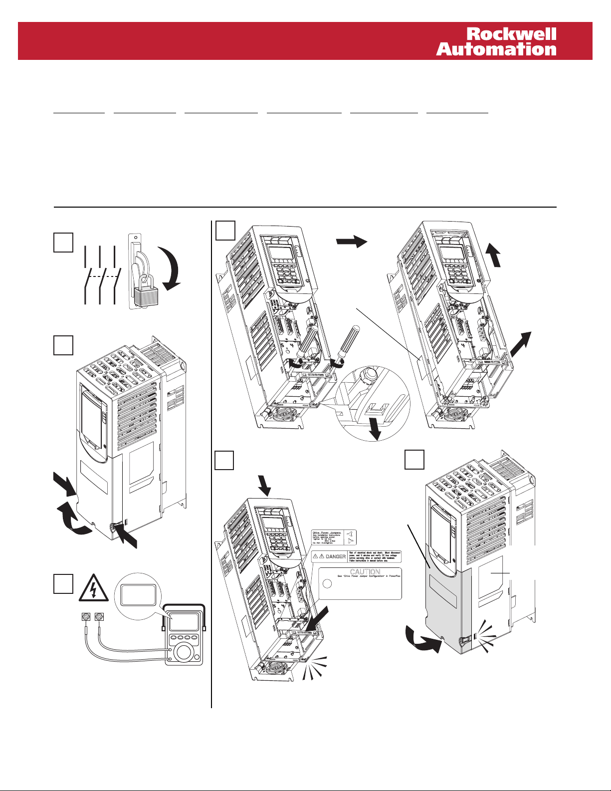
Frames 2 & 3 Type 1 Cover and Chassis
L1 L2 L3
1
(Frame 2 shown)
I
O
2
4
5
SK-R9-CHSS1-F2
SK-R9-CHSS1-F3
(Frame 2 shown)
Manufacturing
Label
6
SK-R1-CVR1-F2
SK-R1-CVR1-F3
3
DC+ DC–
0V
0V
(1)
To receive a replacement Data Nameplate
label, contact U.S. Allen-Bradley Drives
Technical Support, (1) 262.512.8176, with the
serial number from the Manufacturing label
(see step 4 above for location).
Rockwell Automation Publication RA-IN026A-EN-P – November 2009 1
Data
Nameplate
(1)
Label
Page 2
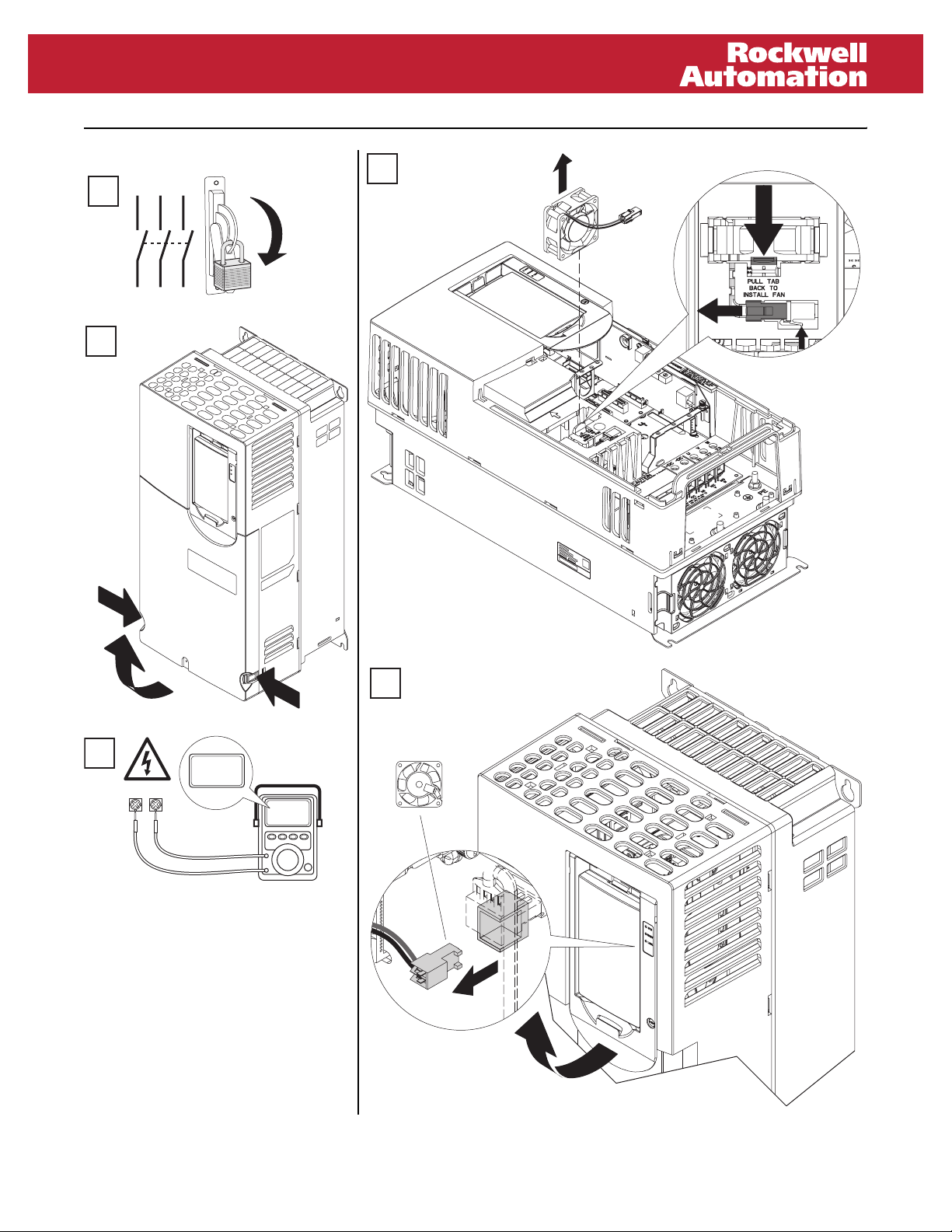
Frames 4 & 5, Type 1 Cover and Chassis
L1 L2 L3
1
(Frame 4 shown)
I
O
2
(Frame 4 shown)
4
3
5
0V
DC+ DC–
0V
2 Rockwell Automation Publication RA-IN026A-EN-P – November 2009
Page 3

Frames 4 & 5, Type 1 Cover and Chassis, Continued
(Frame 4 shown)
6
7
(Frame 4 shown)
9
10
8
Common Bus Drives Only
SK-R9-CHSS1-F4
SK-R9-CHSS1-F5
SK-R9-CHSS2-F5
(Back View of Chassis)
Manufacturing Label
11
SK-R1-CVR1-F4
SK-R1-CVR1-F5
Data Nameplate Label
To receive a replacement
Data Nameplate label,
contact U.S. Allen-Bradley
Drives Technical Support,
(1) 262.512.8176, with the
serial number from the
Manufacturing label (see
step 10 above for location).
Rockwell Automation Publication RA-IN026A-EN-P – November 2009 3
Page 4

Frames 2…5, Type 12 Cover
1
L1 L2 L3
I
Frame 2 Frame 3
12
9
13
12 139
(Frame 4 shown)
2
3
11
4
8
Data Nameplate
Label
6
(same location,
all frame sizes)
2
5
10
(1)
7
1
15 1817
SK-R1-CVR12-F3
14 15
16
1
O
5
7
SK-R1-CVR12-F2
3
10
14 15
(1)
To receive a replacement Data Nameplate label, contact U.S. Allen-Bradley
Drives Technical Support, (1) 262.512.8176, with the serial number from the
Manufacturing label (see step 4 on page 1 or step 10 on page 3 for location).
Frame 4 Frame 5
11 1213
4
8
11
6
2
2x:
3
M4 X 0.7
1
5
4
1
5
8
0V
DC+ DC–
A
0V
9
7
SK-R1-CVR12-F4
10
6
9
13
11
4
7
B
T20
0.34 N-m
(3.0 lb.-in.)
C
0.68 N-m
(6.0 lb.-in.)
4 Rockwell Automation Publication RA-IN026A-EN-P – November 2009
3
14 15
2
3
SK-R1-CVR12-F5
19 21
4
8
12
14
10
6
2
22 20
Page 5

Frame 6 & 7 Type 1 Covers and Legs
1
L1 L2 L3
I
5
Frame 6
SK-R9-LEG1-F6
2
3
DC+ DC–
O
(Frame 6 shown)
0V
0V
T25
3.9 N•m (35 lb•in)
Frame 7
5
T25
SK-R9-LEG1-F7
(Frame 6 shown)
4
90°
3.9 N•m (35 lb•in)
Rockwell Automation Publication RA-IN026A-EN-P – November 2009 5
Page 6

(Frame 6 shown)
6
SK-R1-CVR1-F6
SK-R1-CVR1-F7
90°
7
SK-R1-AD1-F67
Data Nameplate Label
To receive a
replacement Data
Nameplate label,
contact U.S. AllenBradley Drives
Technical Support,
(1) 262.512.8176, with
the serial number from
the Manufacturing label.
Manufacturing Label
*PN-42017*
www.rockwellautomation.com
Power, Control and Information Solutions Headquarters
Americas: Rockwell Automation, 1201 South Second Street, Milwaukee, WI 53204 USA, Tel: (1) 414.382.2000, Fax: (1) 414.382.4444
Europe/Middle East/Africa: Rockwell Automation, Vorstlaan/Boulevard du Souverain 36, 1170 Brussels, Belgium, Tel: (32) 2 663 0600, Fax: (32) 2 663 0640
Asia Pacific: Rockwell Automation, Level 14, Core F, Cyberport 3, 100 Cyberport Road, Hong Kong, Tel: (852) 2887 4788, Fax: (852) 2508 1846
Rockwell Automation Publication RA-IN026A-EN-P – November 2009
Copyright © 2009 Rockwell Automation, Inc. All rights reserved. Printed in USA.
PN-42017
 Loading...