

Page 1

User Manual
PowerFlex 7000 Medium Voltage AC Drive Liquid-Cooled ("C" Frame) - ForGe Control
Publication 7000L-UM301D-EN-P
Page 2
Important User Information
IMPORTANT
Read this document and the documents listed in the additional resources section about installation, configuration, and
operation of this equipment before you install, configure, operate, or maintain this product. Users are required to
familiarize themselves with installation and wiring instructions in addition to requirements of all applicable codes, laws,
and standards.
Activities including installation, adjustments, putting into service, use, assembly, disassembly, and maintenance are required
to be carried out by suitably trained personnel in accordance with applicable code of practice.
If this equipment is used in a manner not specified by the manufacturer, the protection provided by the equipment may be
impaired.
In no event will Rockwell Automation, Inc. be responsible or liable for indirect or consequential damages resulting from the
use or application of this equipment.
The examples and diagrams in this manual are included solely for illustrative purposes. Because of the many variables and
requirements associated with any particular installation, Rockwell Automation, Inc. cannot assume responsibility or
liability for actual use based on the examples and diagrams.
No patent liability is assumed by Rockwell Automation, Inc. with respect to use of information, circuits, equipment, or
software described in this manual.
Reproduction of the contents of this manual, in whole or in part, without written permission of Rockwell Automation,
Inc., is prohibited.
Throughout this manual, when necessary, we use notes to make you aware of safety considerations.
WARNING: Identifies information about practices or circumstances that can cause an explosion in a hazardous environment,
which may lead to personal injury or death, property damage, or economic loss.
ATTENTION: Identifies information about practices or circumstances that can lead to personal injury or death, property
damage, or economic loss. Attentions help you identify a hazard, avoid a hazard, and recognize the consequence.
Identifies information that is critical for successful application and understanding of the product.
Labels may also be on or inside the equipment to provide specific precautions.
SHOCK HAZARD: Labels may be on or inside the equipment, for example, a drive or motor, to alert people that dangerous
voltage may be present.
BURN HAZARD: Labels may be on or inside the equipment, for example, a drive or motor, to alert people that surfaces may
reach dangerous temperatures.
ARC FLASH HAZARD: Labels may be on or inside the equipment, for example, a motor control center, to alert people to
potential Arc Flash. Arc Flash will cause severe injury or death. Wear proper Personal Protective Equipment (PPE). Follow ALL
Regulatory requirements for safe work practices and for Personal Protective Equipment (PPE).
Allen-Bradley, Rockwell Software, Rockwell Automation, and TechConnect are trademarks of Rockwell Automation, Inc.
Trademarks not belonging to Rockwell Automation are property of their respective companies.
Page 3

This manual contains new and updated information.
Summary of Changes
New and Updated
Information
This table summarizes the changes made to this revision.
Top ic Pag e
Changed all references of “tachometer” to “encoder” Throughout
Added HPTC information to Topology section 17
Updated Speed Regulator Bandwidth 24
Updated Torque Regulator Bandwidth 24
Inserted Torque Accuracy with HPTC 24
Added Polish to list of available Languages 25
Added “Dual-port Ethernet/IP” to Communications Protocols 25
Replaced Control Overview block diagram 29
Added “Pipe Materials and Layout” section 76
Added dimensions and torque information to Pipe Flange detail images 77
Inserted “External Piping to the Drive” section 77
Inserted “Controlled Siphon into Open-top Reservoir” section 78
Added Converter Cabinet Components (3300/4160V) image 212
Added Converter Cabinet Components (6600V) image 213
Changed graphic labels for valve locations 217
Changed graphic labels for valve locations 218
Inserted “System Fill and Air Venting” and “Normal Operation” section 218
Replaced Cooling System Overview chart 328
Inserted “Pump Cabinet with Ebara Pumps” image 331
Added “Pump Replacement with Drive Running” section 331
Replaced Pressure Indicator and Switch Locations image 333
Replaced Temperature and Conductivity Sensors image 337
Replaced Deionizer Reservoir Circuit image 338
Inserted “Replacing the Mesh Filters” section 339
Replaced Catalog Number Explanation 411
Updated “When is an Encoder Required?” section and table 414
Replaced Encoder Selection table 415
Added HPTC information to Drive Torque Capabilities table 415
Updated Typical Application Load Torque Profiles 416
Rockwell Automation Publication 7000L-UM301D-EN-P - June 2014 3
Page 4

Summary of Changes
Notes:
4 Rockwell Automation Publication 7000L-UM301D-EN-P - June 2014
Page 5

Overview of Drive
Table of Contents
Chapter 1
Introduction. . . . . . . . . . . . . . . . . . . . . . . . . . . . . . . . . . . . . . . . . . . . . . . . . . . . . 15
Liquid Cooling . . . . . . . . . . . . . . . . . . . . . . . . . . . . . . . . . . . . . . . . . . . . . . . . . . 15
Benefits of Liquid Cooling Include: . . . . . . . . . . . . . . . . . . . . . . . . . . . . 15
Benefits of the 7000L “C” Frame Liquid-cooled Drive: . . . . . . . . . . 16
Topology. . . . . . . . . . . . . . . . . . . . . . . . . . . . . . . . . . . . . . . . . . . . . . . . . . . . . . . . 17
Rectifier Designs . . . . . . . . . . . . . . . . . . . . . . . . . . . . . . . . . . . . . . . . . . . . . . . . . 18
18 Pulse Rectifier. . . . . . . . . . . . . . . . . . . . . . . . . . . . . . . . . . . . . . . . . . . . . 18
Active Front End (AFE Rectifier). . . . . . . . . . . . . . . . . . . . . . . . . . . . . . 18
“Direct-to-Drive” Technology. . . . . . . . . . . . . . . . . . . . . . . . . . . . . . . . . . . . . 19
Motor Compatibility . . . . . . . . . . . . . . . . . . . . . . . . . . . . . . . . . . . . . . . . . . . . . 21
SGCT Features and Benefits . . . . . . . . . . . . . . . . . . . . . . . . . . . . . . . . . . . . . . 22
Specifications . . . . . . . . . . . . . . . . . . . . . . . . . . . . . . . . . . . . . . . . . . . . . . . . . . . . 23
Simplified Electrical Drawings. . . . . . . . . . . . . . . . . . . . . . . . . . . . . . . . . 27
Control Overview . . . . . . . . . . . . . . . . . . . . . . . . . . . . . . . . . . . . . . . . . . . . 29
Direct Vector Control. . . . . . . . . . . . . . . . . . . . . . . . . . . . . . . . . . . . . . . . . . . . 30
Control Hardware . . . . . . . . . . . . . . . . . . . . . . . . . . . . . . . . . . . . . . . . . . . . . . . 30
Operator Interface . . . . . . . . . . . . . . . . . . . . . . . . . . . . . . . . . . . . . . . . . . . . . . . 31
Drive Installation
Chapter 2
Safety and Codes . . . . . . . . . . . . . . . . . . . . . . . . . . . . . . . . . . . . . . . . . . . . . . . . 33
Unpacking and Inspection . . . . . . . . . . . . . . . . . . . . . . . . . . . . . . . . . . . . . . . . 33
Transportation and Handling . . . . . . . . . . . . . . . . . . . . . . . . . . . . . . . . . . . . . 33
Overhead Lifting . . . . . . . . . . . . . . . . . . . . . . . . . . . . . . . . . . . . . . . . . . . . . 34
Rod or Pipe Rollers . . . . . . . . . . . . . . . . . . . . . . . . . . . . . . . . . . . . . . . . . . . 35
Fork Lift Trucks . . . . . . . . . . . . . . . . . . . . . . . . . . . . . . . . . . . . . . . . . . . . . 36
Storage . . . . . . . . . . . . . . . . . . . . . . . . . . . . . . . . . . . . . . . . . . . . . . . . . . . . . . 36
Siting of the Drive. . . . . . . . . . . . . . . . . . . . . . . . . . . . . . . . . . . . . . . . . . . . . . . . 36
Site Considerations. . . . . . . . . . . . . . . . . . . . . . . . . . . . . . . . . . . . . . . . . . . 36
Installation . . . . . . . . . . . . . . . . . . . . . . . . . . . . . . . . . . . . . . . . . . . . . . . . . . . . . . 37
Joining Shipping Splits . . . . . . . . . . . . . . . . . . . . . . . . . . . . . . . . . . . . . . . . . . . 38
Connect the Sections. . . . . . . . . . . . . . . . . . . . . . . . . . . . . . . . . . . . . . . . . . . . . 39
Tools Required (not supplied). . . . . . . . . . . . . . . . . . . . . . . . . . . . . . . . . 39
Install CPVC Piping Splices . . . . . . . . . . . . . . . . . . . . . . . . . . . . . . . . . . 39
Connect Power: M+, L+, M-, L- Power Bus . . . . . . . . . . . . . . . . . . . . 42
Control Wiring Connections . . . . . . . . . . . . . . . . . . . . . . . . . . . . . . . . . . . . . 47
Removal of DC Link Choke Turnbuckle Supports . . . . . . . . . . . . . 54
Removal of Lifting Angles . . . . . . . . . . . . . . . . . . . . . . . . . . . . . . . . . . . . . . . . 54
Shock Indication Labels. . . . . . . . . . . . . . . . . . . . . . . . . . . . . . . . . . . . . . . 55
Installation of Exhaust Air Hood . . . . . . . . . . . . . . . . . . . . . . . . . . . . . . 56
Internally mounted fans. . . . . . . . . . . . . . . . . . . . . . . . . . . . . . . . . . . . . . . 57
Externally mounted fans and fan hood . . . . . . . . . . . . . . . . . . . . . . . . . 58
Typical PowerFlex 7000L Drive Structure Layout. . . . . . . . . . . . . . . 59
Control/Cabling Cabinet. . . . . . . . . . . . . . . . . . . . . . . . . . . . . . . . . . . . . . . . . 59
Major Components . . . . . . . . . . . . . . . . . . . . . . . . . . . . . . . . . . . . . . . . . . . . . . 59
Rockwell Automation Publication 7000L-UM301D-EN-P - June 2014 5
Page 6

Table of Contents
IEC Component and Device Designation . . . . . . . . . . . . . . . . . . . . . . . . . . 68
Power Wiring Selection. . . . . . . . . . . . . . . . . . . . . . . . . . . . . . . . . . . . . . . . . . . 68
General Notes . . . . . . . . . . . . . . . . . . . . . . . . . . . . . . . . . . . . . . . . . . . . . . . . 68
Cable Insulation . . . . . . . . . . . . . . . . . . . . . . . . . . . . . . . . . . . . . . . . . . . . . . 69
Power Cabling Access. . . . . . . . . . . . . . . . . . . . . . . . . . . . . . . . . . . . . . . . . . . . . 71
Access the Customer Power Cable Terminations: . . . . . . . . . . . . . . . 71
Power Connections. . . . . . . . . . . . . . . . . . . . . . . . . . . . . . . . . . . . . . . . . . . . . . . 74
Incoming Connections. . . . . . . . . . . . . . . . . . . . . . . . . . . . . . . . . . . . . . . . 74
Liquid Connections . . . . . . . . . . . . . . . . . . . . . . . . . . . . . . . . . . . . . . . . . . . . . . 75
Liquid-to-Air Heat Exchangers . . . . . . . . . . . . . . . . . . . . . . . . . . . . . . . . 75
Pipe Materials and Layout. . . . . . . . . . . . . . . . . . . . . . . . . . . . . . . . . . . . . . . . . 76
External Piping to the Drive. . . . . . . . . . . . . . . . . . . . . . . . . . . . . . . . . . . . . . . 77
External Piping Cleaning . . . . . . . . . . . . . . . . . . . . . . . . . . . . . . . . . . . . . . 77
Controlled Siphon into Open-top Reservoir . . . . . . . . . . . . . . . . . . . . . . . . 78
Liquid-to-Liquid Heat Exchangers . . . . . . . . . . . . . . . . . . . . . . . . . . . . . . . . 80
Power and Control Wiring. . . . . . . . . . . . . . . . . . . . . . . . . . . . . . . . . . . . . . . . 83
Control Cables . . . . . . . . . . . . . . . . . . . . . . . . . . . . . . . . . . . . . . . . . . . . . . . 83
Encoder Installation Guidelines. . . . . . . . . . . . . . . . . . . . . . . . . . . . . . . . 83
Information Regarding Termination of Customer Cables . . . . . . . . 86
Grounding Practices . . . . . . . . . . . . . . . . . . . . . . . . . . . . . . . . . . . . . . . . . . . . . . 87
Grounding Guidelines and Practices for Drive Signal and Safety
Grounds . . . . . . . . . . . . . . . . . . . . . . . . . . . . . . . . . . . . . . . . . . . . . . . . . . . . . 88
Grounding Requirements and Grounding Specification for
Customers and Power Integrators . . . . . . . . . . . . . . . . . . . . . . . . . . . . . . 88
Identification of Types of Electrical Supplies – Grounded and
Ungrounded Systems . . . . . . . . . . . . . . . . . . . . . . . . . . . . . . . . . . . . . . . . . 89
Ground Bus . . . . . . . . . . . . . . . . . . . . . . . . . . . . . . . . . . . . . . . . . . . . . . . . . . 89
Interlocking. . . . . . . . . . . . . . . . . . . . . . . . . . . . . . . . . . . . . . . . . . . . . . . . . . . . . . 89
Chapter 3
Operator Interface
6 Rockwell Automation Publication 7000L-UM301D-EN-P - June 2014
Chapter Objectives . . . . . . . . . . . . . . . . . . . . . . . . . . . . . . . . . . . . . . . . . . . . . . . 91
Terminology . . . . . . . . . . . . . . . . . . . . . . . . . . . . . . . . . . . . . . . . . . . . . . . . . . . . . 91
Overview . . . . . . . . . . . . . . . . . . . . . . . . . . . . . . . . . . . . . . . . . . . . . . . . . . . . . . . . 92
Keypad . . . . . . . . . . . . . . . . . . . . . . . . . . . . . . . . . . . . . . . . . . . . . . . . . . . . . . . . . . 93
Function (Softkeys) Keys . . . . . . . . . . . . . . . . . . . . . . . . . . . . . . . . . . . . . 93
Cursor (Selection) Keys . . . . . . . . . . . . . . . . . . . . . . . . . . . . . . . . . . . . . . . 93
Data Entry Keys . . . . . . . . . . . . . . . . . . . . . . . . . . . . . . . . . . . . . . . . . . . . . . 94
What is a Screen?. . . . . . . . . . . . . . . . . . . . . . . . . . . . . . . . . . . . . . . . . . . . . . . . . 94
Components . . . . . . . . . . . . . . . . . . . . . . . . . . . . . . . . . . . . . . . . . . . . . . . . . 94
Information Windows . . . . . . . . . . . . . . . . . . . . . . . . . . . . . . . . . . . . . . . . 96
Accessing/Writing to Drive . . . . . . . . . . . . . . . . . . . . . . . . . . . . . . . . . . . 96
Communication Error . . . . . . . . . . . . . . . . . . . . . . . . . . . . . . . . . . . . . . . . 96
Languange Changing. . . . . . . . . . . . . . . . . . . . . . . . . . . . . . . . . . . . . . . . . . 97
General Operation. . . . . . . . . . . . . . . . . . . . . . . . . . . . . . . . . . . . . . . . . . . . 98
Operator Interface Power-up Sequence. . . . . . . . . . . . . . . . . . . . . . . . . . . . . 99
Top Level Menu . . . . . . . . . . . . . . . . . . . . . . . . . . . . . . . . . . . . . . . . . . . . . . . . . 99
How To . . . . . . . . . . . . . . . . . . . . . . . . . . . . . . . . . . . . . . . . . . . . . . . . . . . . . . . . 100
Page 7

Table of Contents
Obtain Help . . . . . . . . . . . . . . . . . . . . . . . . . . . . . . . . . . . . . . . . . . . . . . . . 100
Related Topics . . . . . . . . . . . . . . . . . . . . . . . . . . . . . . . . . . . . . . . . . . . . . . 101
Help on Help . . . . . . . . . . . . . . . . . . . . . . . . . . . . . . . . . . . . . . . . . . . . . . . 102
Modify Operator Interface Operation (Utility) . . . . . . . . . . . . . . . . . . . . 102
Changing Backlight Delay. . . . . . . . . . . . . . . . . . . . . . . . . . . . . . . . . . . . 103
Changing Contrast . . . . . . . . . . . . . . . . . . . . . . . . . . . . . . . . . . . . . . . . . . 104
Setting Time . . . . . . . . . . . . . . . . . . . . . . . . . . . . . . . . . . . . . . . . . . . . . . . . 104
Setting Date . . . . . . . . . . . . . . . . . . . . . . . . . . . . . . . . . . . . . . . . . . . . . . . . 105
Selecting Meters. . . . . . . . . . . . . . . . . . . . . . . . . . . . . . . . . . . . . . . . . . . . . 106
Viewing Revision Levels. . . . . . . . . . . . . . . . . . . . . . . . . . . . . . . . . . . . . . 108
Transfer Data in Memory . . . . . . . . . . . . . . . . . . . . . . . . . . . . . . . . . . . . 109
Picking an Access Level . . . . . . . . . . . . . . . . . . . . . . . . . . . . . . . . . . . . . . 110
Select a Parameter . . . . . . . . . . . . . . . . . . . . . . . . . . . . . . . . . . . . . . . . . . . . . . . 110
Via Groups . . . . . . . . . . . . . . . . . . . . . . . . . . . . . . . . . . . . . . . . . . . . . . . . . 110
Via Name. . . . . . . . . . . . . . . . . . . . . . . . . . . . . . . . . . . . . . . . . . . . . . . . . . . 111
Via Code . . . . . . . . . . . . . . . . . . . . . . . . . . . . . . . . . . . . . . . . . . . . . . . . . . . 113
Edit Text . . . . . . . . . . . . . . . . . . . . . . . . . . . . . . . . . . . . . . . . . . . . . . . . . . . . . . . 114
Configure the Drive . . . . . . . . . . . . . . . . . . . . . . . . . . . . . . . . . . . . . . . . . . . . . 116
Enter/Modify an Access Level . . . . . . . . . . . . . . . . . . . . . . . . . . . . . . . 116
Drive Setup. . . . . . . . . . . . . . . . . . . . . . . . . . . . . . . . . . . . . . . . . . . . . . . . . . . . . 120
Language Selection . . . . . . . . . . . . . . . . . . . . . . . . . . . . . . . . . . . . . . . . . . 121
Modify Parameters . . . . . . . . . . . . . . . . . . . . . . . . . . . . . . . . . . . . . . . . . . 122
Numerical Value . . . . . . . . . . . . . . . . . . . . . . . . . . . . . . . . . . . . . . . . . . . . 122
Enumerated Value. . . . . . . . . . . . . . . . . . . . . . . . . . . . . . . . . . . . . . . . . . . 124
Bit Encoded Value. . . . . . . . . . . . . . . . . . . . . . . . . . . . . . . . . . . . . . . . . . . 125
Analog Ports . . . . . . . . . . . . . . . . . . . . . . . . . . . . . . . . . . . . . . . . . . . . . . . . 126
Fault Masks . . . . . . . . . . . . . . . . . . . . . . . . . . . . . . . . . . . . . . . . . . . . . . . . . 128
User Definable External Text. . . . . . . . . . . . . . . . . . . . . . . . . . . . . . . . . 131
PLC. . . . . . . . . . . . . . . . . . . . . . . . . . . . . . . . . . . . . . . . . . . . . . . . . . . . . . . . 132
XIO. . . . . . . . . . . . . . . . . . . . . . . . . . . . . . . . . . . . . . . . . . . . . . . . . . . . . . . . 133
Message Prompting. . . . . . . . . . . . . . . . . . . . . . . . . . . . . . . . . . . . . . . . . . 134
Store/Retrieve Configuration (NVRAM) . . . . . . . . . . . . . . . . . . . . . 135
Initialize . . . . . . . . . . . . . . . . . . . . . . . . . . . . . . . . . . . . . . . . . . . . . . . . . . . . 135
Save . . . . . . . . . . . . . . . . . . . . . . . . . . . . . . . . . . . . . . . . . . . . . . . . . . . . . . . . 135
Load . . . . . . . . . . . . . . . . . . . . . . . . . . . . . . . . . . . . . . . . . . . . . . . . . . . . . . . 136
Display Parameters
. . . . . . . . . . . . . . . . . . . . . . . . . . . . . . . . . . . . . . . . . . . . . . 137
Custom Group. . . . . . . . . . . . . . . . . . . . . . . . . . . . . . . . . . . . . . . . . . . . . . 138
View Drive Status . . . . . . . . . . . . . . . . . . . . . . . . . . . . . . . . . . . . . . . . . . . . . . . 139
View and Reset Alarms . . . . . . . . . . . . . . . . . . . . . . . . . . . . . . . . . . . . . . . . . . 140
Help for Alarms . . . . . . . . . . . . . . . . . . . . . . . . . . . . . . . . . . . . . . . . . . . . . 141
Request Printouts . . . . . . . . . . . . . . . . . . . . . . . . . . . . . . . . . . . . . . . . . . . . . . . 142
Perform Diagnostic Trending . . . . . . . . . . . . . . . . . . . . . . . . . . . . . . . . . . . . 142
Assigning a Trace. . . . . . . . . . . . . . . . . . . . . . . . . . . . . . . . . . . . . . . . . . . . 144
Setting the Trigger . . . . . . . . . . . . . . . . . . . . . . . . . . . . . . . . . . . . . . . . . . 144
Defining Sample Rate and Positioning . . . . . . . . . . . . . . . . . . . . . . . . 146
Starting the Trace . . . . . . . . . . . . . . . . . . . . . . . . . . . . . . . . . . . . . . . . . . . 146
Flash Memory Transfers . . . . . . . . . . . . . . . . . . . . . . . . . . . . . . . . . . . . . . . . . 148
Rockwell Automation Publication 7000L-UM301D-EN-P - June 2014 7
Page 8

Table of Contents
Format Flash Card. . . . . . . . . . . . . . . . . . . . . . . . . . . . . . . . . . . . . . . . . . . 149
View a Directory. . . . . . . . . . . . . . . . . . . . . . . . . . . . . . . . . . . . . . . . . . . . . 150
Select a Filename . . . . . . . . . . . . . . . . . . . . . . . . . . . . . . . . . . . . . . . . . . . . 151
Enter a Filename. . . . . . . . . . . . . . . . . . . . . . . . . . . . . . . . . . . . . . . . . . . . . 151
Loading Programs (Firmware). . . . . . . . . . . . . . . . . . . . . . . . . . . . . . . . . . . . 152
Parameter Transfers . . . . . . . . . . . . . . . . . . . . . . . . . . . . . . . . . . . . . . . . . . . . . 153
Upload to Operator Interface . . . . . . . . . . . . . . . . . . . . . . . . . . . . . . . . 154
Download from Operator Interface . . . . . . . . . . . . . . . . . . . . . . . . . . . 154
Upload to Memory Card . . . . . . . . . . . . . . . . . . . . . . . . . . . . . . . . . . . . . 155
Download from Memory Card . . . . . . . . . . . . . . . . . . . . . . . . . . . . . . . 155
Parameter File Format . . . . . . . . . . . . . . . . . . . . . . . . . . . . . . . . . . . . . . . 156
Loading Language Modules . . . . . . . . . . . . . . . . . . . . . . . . . . . . . . . . . . . . . . 156
System Programming . . . . . . . . . . . . . . . . . . . . . . . . . . . . . . . . . . . . . . . . . . . . 158
Advanced Screen Operations . . . . . . . . . . . . . . . . . . . . . . . . . . . . . . . . . . . . . 158
Communications Statistics . . . . . . . . . . . . . . . . . . . . . . . . . . . . . . . . . . . 158
Protocol Analyzer. . . . . . . . . . . . . . . . . . . . . . . . . . . . . . . . . . . . . . . . . . . . 159
Print Screen . . . . . . . . . . . . . . . . . . . . . . . . . . . . . . . . . . . . . . . . . . . . . . . . . 160
Memory Dump. . . . . . . . . . . . . . . . . . . . . . . . . . . . . . . . . . . . . . . . . . . . . . 160
Database Download . . . . . . . . . . . . . . . . . . . . . . . . . . . . . . . . . . . . . . . . . 162
Operator Interface Menu Hierarchy Chart . . . . . . . . . . . . . . . . . . . . . . . . 162
What Does It Show? . . . . . . . . . . . . . . . . . . . . . . . . . . . . . . . . . . . . . . . . . 162
How Do You Read It? . . . . . . . . . . . . . . . . . . . . . . . . . . . . . . . . . . . . . . . 163
Example . . . . . . . . . . . . . . . . . . . . . . . . . . . . . . . . . . . . . . . . . . . . . . . . . . . . 163
PCMCIA Memory Card Installation Data . . . . . . . . . . . . . . . . . . . . . . . . 167
Description . . . . . . . . . . . . . . . . . . . . . . . . . . . . . . . . . . . . . . . . . . . . . . . . . 167
Installing the Memory Card . . . . . . . . . . . . . . . . . . . . . . . . . . . . . . . . . . 167
Commissioning
Chapter 4
Start-up Commissioning Services . . . . . . . . . . . . . . . . . . . . . . . . . . . . . . . . . 169
Drive Commissioning. . . . . . . . . . . . . . . . . . . . . . . . . . . . . . . . . . . . . . . . 169
Commissioning the Drive . . . . . . . . . . . . . . . . . . . . . . . . . . . . . . . . . . . . 170
Pre-Commissioning Responsibilities . . . . . . . . . . . . . . . . . . . . . . . . . . . . . . 171
PowerFlex 7000 ‘C’ Frame Pre-Commissioning Checklist . . . . . . . . . . 171
Receiving and Unpacking . . . . . . . . . . . . . . . . . . . . . . . . . . . . . . . . . . . . 171
Installation / Mounting . . . . . . . . . . . . . . . . . . . . . . . . . . . . . . . . . . . . . . 172
Safety . . . . . . . . . . . . . . . . . . . . . . . . . . . . . . . . . . . . . . . . . . . . . . . . . . . . . . . 172
Control Wiring . . . . . . . . . . . . . . . . . . . . . . . . . . . . . . . . . . . . . . . . . . . . . 172
Power Wiring . . . . . . . . . . . . . . . . . . . . . . . . . . . . . . . . . . . . . . . . . . . . . . . 173
Drive Line-up Status . . . . . . . . . . . . . . . . . . . . . . . . . . . . . . . . . . . . . . . . . 173
Cooling System Status . . . . . . . . . . . . . . . . . . . . . . . . . . . . . . . . . . . . . . . 173
Commissioning Preparation. . . . . . . . . . . . . . . . . . . . . . . . . . . . . . . . . . . . . . 175
Recommended Tools and Equipment . . . . . . . . . . . . . . . . . . . . . . . . . 175
Technical Publications. . . . . . . . . . . . . . . . . . . . . . . . . . . . . . . . . . . . . . . . . . . 176
PowerFlex 7000 “C” Frame Manual. . . . . . . . . . . . . . . . . . . . . . . . . . . . . . . 176
PowerFlex 7000 Parameters . . . . . . . . . . . . . . . . . . . . . . . . . . . . . . . . . . . . . . 176
Additional Manuals . . . . . . . . . . . . . . . . . . . . . . . . . . . . . . . . . . . . . . . . . . . . . 176
Resources Required to Complete Drive Commissioning . . . . . . . . . . . . 176
8 Rockwell Automation Publication 7000L-UM301D-EN-P - June 2014
Page 9

Table of Contents
Important Note for Commissioning Engineer . . . . . . . . . . . . . . . . . . . . . 177
Key Steps to Commissioning a PowerFlex 7000 Drive. . . . . . . . . . . . . . 178
PowerFlex 7000 “C” Frame Commissioning Datasheets . . . . . . . . . . . . 179
PowerFlex 7000 “C” Frame Drive Commissioning Checklist . . . . . . . 180
Drive Application Review. . . . . . . . . . . . . . . . . . . . . . . . . . . . . . . . . . . . . . . . 183
Rockwell Automation Drive Line-up Drawings . . . . . . . . . . . . . . . . 183
Electrical System One-line Diagram. . . . . . . . . . . . . . . . . . . . . . . . . . . 184
Verify One-line Diagram on Site. . . . . . . . . . . . . . . . . . . . . . . . . . . . . . 184
Inspect Process . . . . . . . . . . . . . . . . . . . . . . . . . . . . . . . . . . . . . . . . . . . . . . 184
Safety Tests. . . . . . . . . . . . . . . . . . . . . . . . . . . . . . . . . . . . . . . . . . . . . . . . . . . . . 185
Lockout Tagout . . . . . . . . . . . . . . . . . . . . . . . . . . . . . . . . . . . . . . . . . . . . . 185
Step Down Transformer Fusing . . . . . . . . . . . . . . . . . . . . . . . . . . . . . . 186
Fuse and O/L Protection. . . . . . . . . . . . . . . . . . . . . . . . . . . . . . . . . . . . . 186
Installation Review . . . . . . . . . . . . . . . . . . . . . . . . . . . . . . . . . . . . . . . . . . . . . . 186
Inspect for Shipping Damage . . . . . . . . . . . . . . . . . . . . . . . . . . . . . . . . . 186
Inspect Cabinets for Debris . . . . . . . . . . . . . . . . . . . . . . . . . . . . . . . . . . 187
Protective Barriers. . . . . . . . . . . . . . . . . . . . . . . . . . . . . . . . . . . . . . . . . . . 187
Component Grounding. . . . . . . . . . . . . . . . . . . . . . . . . . . . . . . . . . . . . . 187
Information on Splice Kits . . . . . . . . . . . . . . . . . . . . . . . . . . . . . . . . . . . 188
Power Cabling . . . . . . . . . . . . . . . . . . . . . . . . . . . . . . . . . . . . . . . . . . . . . . 188
Control Wiring . . . . . . . . . . . . . . . . . . . . . . . . . . . . . . . . . . . . . . . . . . . . . 188
Liquid-Cooling Connections . . . . . . . . . . . . . . . . . . . . . . . . . . . . . . . . . . . . 189
Service Data . . . . . . . . . . . . . . . . . . . . . . . . . . . . . . . . . . . . . . . . . . . . . . . . . . . . 190
Why this Information is Needed. . . . . . . . . . . . . . . . . . . . . . . . . . . . . . 190
Customer Information . . . . . . . . . . . . . . . . . . . . . . . . . . . . . . . . . . . . . . . . . . 191
Control Power Off Tests . . . . . . . . . . . . . . . . . . . . . . . . . . . . . . . . . . . . . . . . 195
Interlocking. . . . . . . . . . . . . . . . . . . . . . . . . . . . . . . . . . . . . . . . . . . . . . . . . 195
Resistance Checks. . . . . . . . . . . . . . . . . . . . . . . . . . . . . . . . . . . . . . . . . . . . . . . 196
SGCT Testing . . . . . . . . . . . . . . . . . . . . . . . . . . . . . . . . . . . . . . . . . . . . . . 197
SGCT Anode-to-Cathode Resistance . . . . . . . . . . . . . . . . . . . . . . . . . 198
Snubber Resistance (SGCT Device). . . . . . . . . . . . . . . . . . . . . . . . . . . 199
Snubber Capacitance (SGCT Device). . . . . . . . . . . . . . . . . . . . . . . . . 200
SCR Testing . . . . . . . . . . . . . . . . . . . . . . . . . . . . . . . . . . . . . . . . . . . . . . . . 200
SCR Anode-to-Cathode Resistance . . . . . . . . . . . . . . . . . . . . . . . . . . . 201
SCR Sharing Resistance Test . . . . . . . . . . . . . . . . . . . . . . . . . . . . . . . . . 202
SCR Gate-to-cathode Resistance. . . . . . . . . . . . . . . . . . . . . . . . . . . . . . 203
Snubber Resistance (SCR Device) . . . . . . . . . . . . . . . . . . . . . . . . . . . . 204
Snubber Capacitance (SCR Device). . . . . . . . . . . . . . . . . . . . . . . . . . . 205
Control Power Tests . . . . . . . . . . . . . . . . . . . . . . . . . . . . . . . . . . . . . . . . . . . . 206
Three-Phase Input . . . . . . . . . . . . . . . . . . . . . . . . . . . . . . . . . . . . . . . . . . 207
Three-Phase Input / Single Phase Input . . . . . . . . . . . . . . . . . . . . . . . 207
Power Supply Tests. . . . . . . . . . . . . . . . . . . . . . . . . . . . . . . . . . . . . . . . . . 208
Circuit Board Healthy Lights. . . . . . . . . . . . . . . . . . . . . . . . . . . . . . . . . 208
Control Power Transformer (CPT). . . . . . . . . . . . . . . . . . . . . . . . . . . 208
AC/DC Converter (PS1) . . . . . . . . . . . . . . . . . . . . . . . . . . . . . . . . . . . . 209
DC/DC Converter (PS2). . . . . . . . . . . . . . . . . . . . . . . . . . . . . . . . . . . . 210
SGCT Power Supplies (IGDPS). . . . . . . . . . . . . . . . . . . . . . . . . . . . . . 211
Rockwell Automation Publication 7000L-UM301D-EN-P - June 2014 9
Page 10

Table of Contents
IGDPS Board LEDs . . . . . . . . . . . . . . . . . . . . . . . . . . . . . . . . . . . . . . . . . 214
Commissioning the Cooling System . . . . . . . . . . . . . . . . . . . . . . . . . . . . . . 214
Heat Exchanger Checks . . . . . . . . . . . . . . . . . . . . . . . . . . . . . . . . . . . . . . 215
Pumping Cabinet Control Power Checks. . . . . . . . . . . . . . . . . . . . . . 216
System Fill . . . . . . . . . . . . . . . . . . . . . . . . . . . . . . . . . . . . . . . . . . . . . . . . . . 217
System Fill and Air Venting . . . . . . . . . . . . . . . . . . . . . . . . . . . . . . . . . . 218
Normal Operation. . . . . . . . . . . . . . . . . . . . . . . . . . . . . . . . . . . . . . . . . . . 220
Gating Tests . . . . . . . . . . . . . . . . . . . . . . . . . . . . . . . . . . . . . . . . . . . . . . . . . . . . 220
Gating Test Mode . . . . . . . . . . . . . . . . . . . . . . . . . . . . . . . . . . . . . . . . . . . 220
SCR Firing Test . . . . . . . . . . . . . . . . . . . . . . . . . . . . . . . . . . . . . . . . . . . . . 222
SGCT Firing Test . . . . . . . . . . . . . . . . . . . . . . . . . . . . . . . . . . . . . . . . . . . 224
System Test . . . . . . . . . . . . . . . . . . . . . . . . . . . . . . . . . . . . . . . . . . . . . . . . . . . . . 225
System Test Mode . . . . . . . . . . . . . . . . . . . . . . . . . . . . . . . . . . . . . . . . . . . 225
Start/Stop Control Circuit . . . . . . . . . . . . . . . . . . . . . . . . . . . . . . . . . . . 226
Status Indicators. . . . . . . . . . . . . . . . . . . . . . . . . . . . . . . . . . . . . . . . . . . . . 227
Analog I/O . . . . . . . . . . . . . . . . . . . . . . . . . . . . . . . . . . . . . . . . . . . . . . . . . 227
Configurable Alarms. . . . . . . . . . . . . . . . . . . . . . . . . . . . . . . . . . . . . . . . . 231
18 Pulse Phasing Test . . . . . . . . . . . . . . . . . . . . . . . . . . . . . . . . . . . . . . . . . . . . 231
Line Terminal Resistance Measurements . . . . . . . . . . . . . . . . . . . . . . 232
Application of Medium Voltage. . . . . . . . . . . . . . . . . . . . . . . . . . . . . . . 233
Input Phasing Check. . . . . . . . . . . . . . . . . . . . . . . . . . . . . . . . . . . . . . . . . 233
DC Current Test. . . . . . . . . . . . . . . . . . . . . . . . . . . . . . . . . . . . . . . . . . . . . . . . 235
Tuning Procedure . . . . . . . . . . . . . . . . . . . . . . . . . . . . . . . . . . . . . . . . . . . . . . . 238
1. Rectifier . . . . . . . . . . . . . . . . . . . . . . . . . . . . . . . . . . . . . . . . . . . . . . . . . . 238
2. Motor Impedance . . . . . . . . . . . . . . . . . . . . . . . . . . . . . . . . . . . . . . . . . 243
3. FluxSpeed Regulator [INDUCTION MOTORS] . . . . . . . . . . . 244
4. FluxSpeed Regulator [SYNCHRONOUS MOTORS] . . . . . . . 249
Running the Load . . . . . . . . . . . . . . . . . . . . . . . . . . . . . . . . . . . . . . . . . . . . . . . 253
Motor Starting Torque. . . . . . . . . . . . . . . . . . . . . . . . . . . . . . . . . . . . . . . 253
Reaching Specific Load Points . . . . . . . . . . . . . . . . . . . . . . . . . . . . . . . . 253
Capturing Data . . . . . . . . . . . . . . . . . . . . . . . . . . . . . . . . . . . . . . . . . . . . . . . . . 255
Drive Input Voltage Phasing Checks . . . . . . . . . . . . . . . . . . . . . . . . . . . . . . 255
Summary: . . . . . . . . . . . . . . . . . . . . . . . . . . . . . . . . . . . . . . . . . . . . . . . . . . . 255
Harmonic Analysis
(required for AFE drives only) . . . . . . . . . . . . . . . . . . . . . . . . . . . . . . . . . . . . 257
Summary: . . . . . . . . . . . . . . . . . . . . . . . . . . . . . . . . . . . . . . . . . . . . . . . . . . . 257
DC Current Test. . . . . . . . . . . . . . . . . . . . . . . . . . . . . . . . . . . . . . . . . . . . . . . . 258
Summary:
. . . . . . . . . . . . . . . . . . . . . . . . . . . . . . . . . . . . . . . . . . . . . . . . . . . 258
Load Test. . . . . . . . . . . . . . . . . . . . . . . . . . . . . . . . . . . . . . . . . . . . . . . . . . . . . . . 259
Synchronous Transfer . . . . . . . . . . . . . . . . . . . . . . . . . . . . . . . . . . . . . . . . . . . 261
10 Rockwell Automation Publication 7000L-UM301D-EN-P - June 2014
Page 11

Chapter 5
Table of Contents
Component Definition and
Maintenance
Control / Cabling Cabinet Components. . . . . . . . . . . . . . . . . . . . . . . . . . 266
Voltage-Sensing Assembly . . . . . . . . . . . . . . . . . . . . . . . . . . . . . . . . . . . . . . . 269
Voltage-Sensing Circuit Board Assembly Replacement . . . . . . . . . . . . . 269
Input Transient Protection . . . . . . . . . . . . . . . . . . . . . . . . . . . . . . . . . . . . . . 270
Overview . . . . . . . . . . . . . . . . . . . . . . . . . . . . . . . . . . . . . . . . . . . . . . . . . . . 270
Transient Suppression Network (TSN) . . . . . . . . . . . . . . . . . . . . . . . . . . . 271
Description . . . . . . . . . . . . . . . . . . . . . . . . . . . . . . . . . . . . . . . . . . . . . . . . . 271
MOV Suppressor. . . . . . . . . . . . . . . . . . . . . . . . . . . . . . . . . . . . . . . . . . . . 271
MOV Fuse. . . . . . . . . . . . . . . . . . . . . . . . . . . . . . . . . . . . . . . . . . . . . . . . . . 272
Transient Suppression Network Fuse Replacement . . . . . . . . . . . . . . . . 273
Metal-Oxide Varistor Replacement . . . . . . . . . . . . . . . . . . . . . . . . . . . . . . . 274
Surge Arresters. . . . . . . . . . . . . . . . . . . . . . . . . . . . . . . . . . . . . . . . . . . . . . . . . . 275
Description . . . . . . . . . . . . . . . . . . . . . . . . . . . . . . . . . . . . . . . . . . . . . . . . . 275
Operation . . . . . . . . . . . . . . . . . . . . . . . . . . . . . . . . . . . . . . . . . . . . . . . . . . 276
Surge Arrester Replacement . . . . . . . . . . . . . . . . . . . . . . . . . . . . . . . . . . 277
Field Test and Care. . . . . . . . . . . . . . . . . . . . . . . . . . . . . . . . . . . . . . . . . . 278
Output Grounding Network Capacitor Replacement . . . . . . . . . . . . . . 278
Ground Filter Replacement . . . . . . . . . . . . . . . . . . . . . . . . . . . . . . . . . . . . . . 280
Hall Effect Sensor Replacement . . . . . . . . . . . . . . . . . . . . . . . . . . . . . . . . . . 281
Current Transformer Replacement . . . . . . . . . . . . . . . . . . . . . . . . . . . . . . . 282
Filter Capacitor Cabinet. . . . . . . . . . . . . . . . . . . . . . . . . . . . . . . . . . . . . . . . . 283
Filter Capacitors . . . . . . . . . . . . . . . . . . . . . . . . . . . . . . . . . . . . . . . . . . . . 283
Filter Capacitor Replacement . . . . . . . . . . . . . . . . . . . . . . . . . . . . . . . . 284
Testing Filter Capacitors. . . . . . . . . . . . . . . . . . . . . . . . . . . . . . . . . . . . . 285
Converter Cabinet Components . . . . . . . . . . . . . . . . . . . . . . . . . . . . . 287
Converter Cabinet . . . . . . . . . . . . . . . . . . . . . . . . . . . . . . . . . . . . . . . . . . . . . . 289
PowerCage™ . . . . . . . . . . . . . . . . . . . . . . . . . . . . . . . . . . . . . . . . . . . . . . . . . . . . 289
SGCT and Snubber Circuit. . . . . . . . . . . . . . . . . . . . . . . . . . . . . . . . . . . . . . 291
Checking Clamping Pressure. . . . . . . . . . . . . . . . . . . . . . . . . . . . . . . . . . . . . 292
Clamping Pressure Adjustment. . . . . . . . . . . . . . . . . . . . . . . . . . . . . . . 292
Symmetrical Gate Commutated Thyristor Replacement. . . . . . . . . . . . 293
Silicon Controlled Rectifier and SCR Self-Powered Gate Driver Board
Replacement. . . . . . . . . . . . . . . . . . . . . . . . . . . . . . . . . . . . . . . . . . . . . . . . . . . . 296
Detachment of Coolant System from PowerCage Modules . . . . . . . . . 299
Reconnecting the Coolant System to a PowerCage Module . . . . . 303
Chill Block Removal and Replacement. . . . . . . . . . . . . . . . . . . . . . . . . . . . 303
Instructions for removing Chill Block assembly . . . . . . . . . . . . . . . . 303
Instructions for inserting Chill Block assembly. . . . . . . . . . . . . . . . . 304
PowerCage Removal and Replacement. . . . . . . . . . . . . . . . . . . . . . . . . . . . 305
Snubber Resistors . . . . . . . . . . . . . . . . . . . . . . . . . . . . . . . . . . . . . . . . . . . . . . . 306
Testing Snubber Resistors. . . . . . . . . . . . . . . . . . . . . . . . . . . . . . . . . . . . 307
Sharing Resistors . . . . . . . . . . . . . . . . . . . . . . . . . . . . . . . . . . . . . . . . . . . . . . . . 307
Testing Sharing Resistors . . . . . . . . . . . . . . . . . . . . . . . . . . . . . . . . . . . . 308
Snubber and Sharing Resistor Replacement. . . . . . . . . . . . . . . . . . . . . . . . 309
Self-Powered Gate Driver Board – SPGDB. . . . . . . . . . . . . . . . . . . . . . . . 311
Description . . . . . . . . . . . . . . . . . . . . . . . . . . . . . . . . . . . . . . . . . . . . . . . . . 311
Rockwell Automation Publication 7000L-UM301D-EN-P - June 2014 11
Page 12

Table of Contents
Board Calibration . . . . . . . . . . . . . . . . . . . . . . . . . . . . . . . . . . . . . . . . . . . 311
Test points description. . . . . . . . . . . . . . . . . . . . . . . . . . . . . . . . . . . . . . . 311
Terminal/connections description . . . . . . . . . . . . . . . . . . . . . . . . . . . . 312
Testing procedure for SCR self-powered gate driver board . . . . . . . . . . 313
Equipment needed: . . . . . . . . . . . . . . . . . . . . . . . . . . . . . . . . . . . . . . . . . . 313
Procedure: . . . . . . . . . . . . . . . . . . . . . . . . . . . . . . . . . . . . . . . . . . . . . . . . . . 313
Fiber Optic Cabling . . . . . . . . . . . . . . . . . . . . . . . . . . . . . . . . . . . . . . . . . . . . . 317
DC Link Reactor . . . . . . . . . . . . . . . . . . . . . . . . . . . . . . . . . . . . . . . . . . . . 319
Control Power Components . . . . . . . . . . . . . . . . . . . . . . . . . . . . . . . . . . . . . 321
Ride-Through . . . . . . . . . . . . . . . . . . . . . . . . . . . . . . . . . . . . . . . . . . . . . . . 321
AC/DC Power Supply. . . . . . . . . . . . . . . . . . . . . . . . . . . . . . . . . . . . . . . . . . . 322
Description . . . . . . . . . . . . . . . . . . . . . . . . . . . . . . . . . . . . . . . . . . . . . . . . . 322
Location . . . . . . . . . . . . . . . . . . . . . . . . . . . . . . . . . . . . . . . . . . . . . . . . . . . . 323
Terminal / Connections Descriptions . . . . . . . . . . . . . . . . . . . . . . . . . 324
Replacement Procedure . . . . . . . . . . . . . . . . . . . . . . . . . . . . . . . . . . . . . . 325
UPS Option . . . . . . . . . . . . . . . . . . . . . . . . . . . . . . . . . . . . . . . . . . . . . . . . . . . . 326
UPS Replacement Procedure . . . . . . . . . . . . . . . . . . . . . . . . . . . . . . . . . 327
Cooling System . . . . . . . . . . . . . . . . . . . . . . . . . . . . . . . . . . . . . . . . . . . . . . . . . 328
Cooling Circuit . . . . . . . . . . . . . . . . . . . . . . . . . . . . . . . . . . . . . . . . . . . . . 329
Chill Blocks . . . . . . . . . . . . . . . . . . . . . . . . . . . . . . . . . . . . . . . . . . . . . . . . . 329
Coolant Pumps. . . . . . . . . . . . . . . . . . . . . . . . . . . . . . . . . . . . . . . . . . . . . . 329
Pump Maintenance and Replacement . . . . . . . . . . . . . . . . . . . . . . . . . . . . . 330
Pump Seal Replacement . . . . . . . . . . . . . . . . . . . . . . . . . . . . . . . . . . . . . . 330
Pump Replacement with Drive Running. . . . . . . . . . . . . . . . . . . . . . . 331
Piping, Tubing and Connectors. . . . . . . . . . . . . . . . . . . . . . . . . . . . . . . 333
Non-Return Valves . . . . . . . . . . . . . . . . . . . . . . . . . . . . . . . . . . . . . . . . . . 333
Pressure Indicator . . . . . . . . . . . . . . . . . . . . . . . . . . . . . . . . . . . . . . . . . . . 334
Pressure Switch. . . . . . . . . . . . . . . . . . . . . . . . . . . . . . . . . . . . . . . . . . . . . . 334
Thermostatic Valve . . . . . . . . . . . . . . . . . . . . . . . . . . . . . . . . . . . . . . . . . . 334
Thermostatic Valve Replacement . . . . . . . . . . . . . . . . . . . . . . . . . . . . . 334
Repair Instructions - Element Testing . . . . . . . . . . . . . . . . . . . . . . . . . 335
Element Replacing . . . . . . . . . . . . . . . . . . . . . . . . . . . . . . . . . . . . . . . . . . . 335
Heat Exchanger . . . . . . . . . . . . . . . . . . . . . . . . . . . . . . . . . . . . . . . . . . . . . 336
Fluid Conductivity . . . . . . . . . . . . . . . . . . . . . . . . . . . . . . . . . . . . . . . . . . 337
Temperature Sensor . . . . . . . . . . . . . . . . . . . . . . . . . . . . . . . . . . . . . . . . . 337
De-Ionizing Cartridge and Mesh Filter . . . . . . . . . . . . . . . . . . . . . . . . 338
Replacing the Mesh Filters. . . . . . . . . . . . . . . . . . . . . . . . . . . . . . . . . . . . 339
Reservoir Circuit . . . . . . . . . . . . . . . . . . . . . . . . . . . . . . . . . . . . . . . . . . . . 340
Fluid Top-up. . . . . . . . . . . . . . . . . . . . . . . . . . . . . . . . . . . . . . . . . . . . . . . . 340
Strainers . . . . . . . . . . . . . . . . . . . . . . . . . . . . . . . . . . . . . . . . . . . . . . . . . . . . 340
Coolant. . . . . . . . . . . . . . . . . . . . . . . . . . . . . . . . . . . . . . . . . . . . . . . . . . . . . 341
Maintaining Coolant Ratio. . . . . . . . . . . . . . . . . . . . . . . . . . . . . . . . . . . 342
Leakage Checks. . . . . . . . . . . . . . . . . . . . . . . . . . . . . . . . . . . . . . . . . . . . . . 343
System Drain. . . . . . . . . . . . . . . . . . . . . . . . . . . . . . . . . . . . . . . . . . . . . . . . 344
Low Voltage Control Section. . . . . . . . . . . . . . . . . . . . . . . . . . . . . . . . . . . . . 344
DC/DC Power SupplyDescription . . . . . . . . . . . . . . . . . . . . . . . . . . . . . . . 345
Description . . . . . . . . . . . . . . . . . . . . . . . . . . . . . . . . . . . . . . . . . . . . . . . . . 345
12 Rockwell Automation Publication 7000L-UM301D-EN-P - June 2014
Page 13

Table of Contents
Terminal/Connections Descriptions. . . . . . . . . . . . . . . . . . . . . . . . . . 346
Replacement Procedure for DC/DC Power Supply . . . . . . . . . . . . 347
Printed Circuit Board Replacement. . . . . . . . . . . . . . . . . . . . . . . . . . . . . . . 348
IO Connectors on Control Boards. . . . . . . . . . . . . . . . . . . . . . . . . . . . 348
Drive Processor Module . . . . . . . . . . . . . . . . . . . . . . . . . . . . . . . . . . . . . . . . . 349
Drive Processor Module Replacement. . . . . . . . . . . . . . . . . . . . . . . . . 351
Instructions to Replace the Drive Processor Module. . . . . . . . . . . . 351
ACB Analog Control Board . . . . . . . . . . . . . . . . . . . . . . . . . . . . . . . . . . . . . 353
LEDs. . . . . . . . . . . . . . . . . . . . . . . . . . . . . . . . . . . . . . . . . . . . . . . . . . . . . . . 357
Interface Module (IFM) . . . . . . . . . . . . . . . . . . . . . . . . . . . . . . . . . . . . . 357
Analog Inputs and Outputs . . . . . . . . . . . . . . . . . . . . . . . . . . . . . . . . . . 357
Current Loop Transmitter. . . . . . . . . . . . . . . . . . . . . . . . . . . . . . . . . . . . . . . 358
Isolated Process Receiver . . . . . . . . . . . . . . . . . . . . . . . . . . . . . . . . . . . . . 358
Non-Isolated Process Outputs. . . . . . . . . . . . . . . . . . . . . . . . . . . . . . . . 359
Auxiliary +24V Power Supply . . . . . . . . . . . . . . . . . . . . . . . . . . . . . . . . 360
ACB Analog Control Board Replacement . . . . . . . . . . . . . . . . . . . . . 360
Tachometer Feedback Board . . . . . . . . . . . . . . . . . . . . . . . . . . . . . . . . . . . . . 361
Encoder Options . . . . . . . . . . . . . . . . . . . . . . . . . . . . . . . . . . . . . . . . . . . . 361
Quadrature Encoder Operation . . . . . . . . . . . . . . . . . . . . . . . . . . . . . . 364
Positional Encoder Operations . . . . . . . . . . . . . . . . . . . . . . . . . . . . . . . 365
Positional Encoder Guidelines. . . . . . . . . . . . . . . . . . . . . . . . . . . . . . . . 366
External Input/Output Boards . . . . . . . . . . . . . . . . . . . . . . . . . . . . . . . . . . . 367
External Input/Output Board Replacement . . . . . . . . . . . . . . . . . . . 368
Optical Interface Boards (OIB) . . . . . . . . . . . . . . . . . . . . . . . . . . . . . . . . . . 369
Optical Interface Board Replacement . . . . . . . . . . . . . . . . . . . . . . . . . 370
Optical Interface Base Board (OIBB) . . . . . . . . . . . . . . . . . . . . . . . . . . . . . 372
Optical Interface Base Board Test Points . . . . . . . . . . . . . . . . . . . . . . 373
Downloading Firmware . . . . . . . . . . . . . . . . . . . . . . . . . . . . . . . . . . . . . . . . . 374
Introduction . . . . . . . . . . . . . . . . . . . . . . . . . . . . . . . . . . . . . . . . . . . . . . . . 374
Overview . . . . . . . . . . . . . . . . . . . . . . . . . . . . . . . . . . . . . . . . . . . . . . . . . . . 374
PowerFlex 7000 in Download Mode . . . . . . . . . . . . . . . . . . . . . . . . . . 377
Reloading the Parameters . . . . . . . . . . . . . . . . . . . . . . . . . . . . . . . . . . . . . . . . 380
Setting Elapsed Time . . . . . . . . . . . . . . . . . . . . . . . . . . . . . . . . . . . . . . . . . . . . 381
Downloading the Terminal Firmware. . . . . . . . . . . . . . . . . . . . . . . . . . . . . 382
Using Flash Memory Card . . . . . . . . . . . . . . . . . . . . . . . . . . . . . . . . . . . 382
DOSFWDL . . . . . . . . . . . . . . . . . . . . . . . . . . . . . . . . . . . . . . . . . . . . . . . . 382
Method. . . . . . . . . . . . . . . . . . . . . . . . . . . . . . . . . . . . . . . . . . . . . . . . . . . . . 383
Setting up Diagnostic Trending
. . . . . . . . . . . . . . . . . . . . . . . . . . . . . . . . . . 383
Diagnostic Setup . . . . . . . . . . . . . . . . . . . . . . . . . . . . . . . . . . . . . . . . . . . . 384
Setting up the Trend. . . . . . . . . . . . . . . . . . . . . . . . . . . . . . . . . . . . . . . . . 384
Printing (Uploading) Data from the Drive . . . . . . . . . . . . . . . . . . . . . . . . 390
Overview . . . . . . . . . . . . . . . . . . . . . . . . . . . . . . . . . . . . . . . . . . . . . . . . . . . 390
Creating an empty notepad (.txt) file. . . . . . . . . . . . . . . . . . . . . . . . . . 391
Setting up HyperTerminal Connection . . . . . . . . . . . . . . . . . . . . . . . 393
Uploading the Data from the drive. . . . . . . . . . . . . . . . . . . . . . . . . . . . 395
Printing (Uploading) Control Data. . . . . . . . . . . . . . . . . . . . . . . . . . . . . . . 398
Set up HyperTerminal connection. . . . . . . . . . . . . . . . . . . . . . . . . . . . 399
Rockwell Automation Publication 7000L-UM301D-EN-P - June 2014 13
Page 14

Table of Contents
Catalog Number Explanation
Printing Control Data . . . . . . . . . . . . . . . . . . . . . . . . . . . . . . . . . . . . . . . 400
Environmental Considerations . . . . . . . . . . . . . . . . . . . . . . . . . . . . . . . . . . . 402
Hazardous Materials . . . . . . . . . . . . . . . . . . . . . . . . . . . . . . . . . . . . . . . . . 402
Disposal . . . . . . . . . . . . . . . . . . . . . . . . . . . . . . . . . . . . . . . . . . . . . . . . . . . . 404
Preventive Maintenance Check List. . . . . . . . . . . . . . . . . . . . . . . . . . . . . . . 404
Operational Maintenance . . . . . . . . . . . . . . . . . . . . . . . . . . . . . . . . . . . . . . . . 404
Annual Maintenance . . . . . . . . . . . . . . . . . . . . . . . . . . . . . . . . . . . . . . . . . . . . 405
Initial Information Gathering . . . . . . . . . . . . . . . . . . . . . . . . . . . . . . . . 405
Physical Checks (NO Medium Voltage and NO Control Power) 406
Control Power Checks (No Medium Voltage) . . . . . . . . . . . . . . . . . 407
Final Power Checks before Restarting . . . . . . . . . . . . . . . . . . . . . . . . . 407
Additional Tasks During Preventive Maintenance. . . . . . . . . . . . . . 408
Final Reporting. . . . . . . . . . . . . . . . . . . . . . . . . . . . . . . . . . . . . . . . . . . . . . 408
Time Estimations. . . . . . . . . . . . . . . . . . . . . . . . . . . . . . . . . . . . . . . . . . . . 409
Tool / Parts / Information Requirements. . . . . . . . . . . . . . . . . . . . . . 409
Appendix A
PowerFlex 7000 Drive Selection Explanation . . . . . . . . . . . . . . . . . . . . . . 413
Service Duty Rating, Continuous Current Rating & Altitude Rating
Code . . . . . . . . . . . . . . . . . . . . . . . . . . . . . . . . . . . . . . . . . . . . . . . . . . . . . . . 413
When is an Encoder Required? . . . . . . . . . . . . . . . . . . . . . . . . . . . . . . . . . . . 414
PowerFlex 7000 Drive Performance (Torque Capabilities). . . . . . . . . . 415
Glossary of Terms . . . . . . . . . . . . . . . . . . . . . . . . . . . . . . . . . . . . . . . . . . . . . . . 416
Torque Requirements for Threaded
Fasteners
Meggering
Preventative Maintenance Schedule
Appendix B
Torque Requirements . . . . . . . . . . . . . . . . . . . . . . . . . . . . . . . . . . . . . . . . . . . 419
Appendix C
Drive Meggering . . . . . . . . . . . . . . . . . . . . . . . . . . . . . . . . . . . . . . . . . . . . . . . . 421
Meggering the PowerFlex 7000 . . . . . . . . . . . . . . . . . . . . . . . . . . . . . . . . . . . 421
Equipment Required. . . . . . . . . . . . . . . . . . . . . . . . . . . . . . . . . . . . . . . . . 422
Procedure . . . . . . . . . . . . . . . . . . . . . . . . . . . . . . . . . . . . . . . . . . . . . . . . . . . 422
Appendix D
PowerFlex 7000 Maintenance Schedule . . . . . . . . . . . . . . . . . . . . . . . . . . . 427
I – Inspection . . . . . . . . . . . . . . . . . . . . . . . . . . . . . . . . . . . . . . . . . . . . . . . 427
M – Maintenance. . . . . . . . . . . . . . . . . . . . . . . . . . . . . . . . . . . . . . . . . . . . 427
R – Replacement . . . . . . . . . . . . . . . . . . . . . . . . . . . . . . . . . . . . . . . . . . . . 427
C – Cleaning. . . . . . . . . . . . . . . . . . . . . . . . . . . . . . . . . . . . . . . . . . . . . . . . 427
Rv – Review. . . . . . . . . . . . . . . . . . . . . . . . . . . . . . . . . . . . . . . . . . . . . . . . . 428
RFB/R – Refurbishment/Replacement . . . . . . . . . . . . . . . . . . . . . . . . 428
14 Rockwell Automation Publication 7000L-UM301D-EN-P - June 2014
Page 15

Overview of Drive
Chapter 1
Introduction
The PowerFlex® 7000 represents the third generation of medium voltage drives at
Rockwell Automation. The PowerFlex 7000 medium voltage AC drive is part of
the PowerFlex family of AC drive products. The Allen-Bradley PowerFlex® family
of Drives incorporates leading-edge technology, embedded communications, and
significant commonality across multiple platforms, networks, operator interface
programming and hardware. Designed for end users, solution providers and
OEMs, PowerFlex 7000 liquid-cooled drives meet applications ranging from
3000...9000 horsepower (2240...6715 kW).
The PowerFlex 7000L is a general purpose stand alone medium voltage drive that
controls speed, torque, direction, starting, and stopping of standard
asynchronous or synchronous AC motors. It is intended for use on a host of
standard and specialty applications such as fans, pumps, compressors, mixers,
conveyors, kilns, fan-pumps, and test stands. Primary industries for these
applications include petrochemical, cement, mining and metals, forest products,
power generation, and water / waste water.
The PowerFlex 7000L is a global product that adheres to the most common
standards from NEC, IEC, NEMA, UL, and CSA. It is available with the world’s
most common supply voltages at medium voltage, from 2400...6600 volts.
The design focus is on high reliability, ease of use, and lower total cost of
ownership.
(1)
Liquid Cooling
The PowerFlex 7000L “C” Frame liquid-cooled drive utilizes a closed loop
system to cool the converter main power components and the integral DC link
inductor.
Benefits of Liquid Cooling Include:
• Smaller drive dimension compared to air-cooled drives of similar rating
• Higher power rating capability
• Quiet operation in control room
• Low loss rejection to the control room reduces air conditioner loading
• Majority of losses rejected outside the control room via a liquid-to-air or
liquid-to-liquid type heat exchanger
(1) For 2400V and 3300V designs, contact factory.
Rockwell Automation Publication 7000L-UM301D-EN-P - June 2014 15
Page 16

Chapter 1 Overview of Drive
Benefits of the 7000L “C” Frame Liquid-cooled Drive:
• Completely integrated MV drive package reduces customer installation
costs and start-up time.
• Higher power rating capability (up to 9000 hp / 6715 kW)
• 18 Pulse and AFE rectifiers for low harmonic solutions that meet IEEE
519-1992 Harmonic Guidelines
• Motor friendly current and voltage output waveforms for use with
standard new and existing motors
– Inverter duty motors not required
– Motor temperature derating not required
– No additional dv/dt or peak voltage stress to motor insulation system
– Tested up to 15 kilometers (9.3 miles) cable distance between drive and
motor
• Spacious cable termination cabinet for ease of use by installation
contractor
• Cable termination stabs accommodate:
– 3 cables in / 3 cables out (Direct-to-Drive or AFE rectifier)
– 9 cables in / 3 cables out (18 Pulse)
– Top or bottom entry and exit of line and load cables
• 90% of drive losses are rejected outside the control room
• Integral liquid-cooled DC link inductor reduces overall dimension and
eliminates external interwiring.
• Integral pumping panel includes:
– Line supply c/w disconnect and fusing
– Closed loop coolant system
– Iron and chloride free liquid ethyl-glycol / deionized water mixture
3
– Low conductivity coolant (1-2 micro-Siemens / cm
– Isolated from medium voltage
– Fully serviceable low voltage compartment isolated from medium
voltage power
– Monitors coolant temperature, flow, level, conductivity, and pressure
– Redundant pumping system (optional)
– Automatic pump change over on pump failure
– 1/2 turn valves with quick disconnect couplers for pump replacement
when drive is operating
– Full drip tray to contain any spilled coolant
– Drain and fill pump for convenient filling
– Industrial schedule 80 CPVC piping for pump panel, headers and
manifolds (no condensation possibility)
– Control hardware for cycling of main / redundant cooling pumps and
heat exchanger fans
• “Plug and play” Power Cage concept
– Central location for easy access to all main power components
)
16 Rockwell Automation Publication 7000L-UM301D-EN-P - June 2014
Page 17
Overview of Drive Chapter 1
2U (X1)
2V (X2)
2W (X3)
SGCT’s
LINE CONVERTER
DC LINK
L+
M+
SGCT’s
MACHINE CONVERTER
U (T1)
V (T2)
W (T3)
L-
M-
1U
1V
1W
LR
– Common modular design for rectifier / inverter
– Same concept as air-cooled drive for front access, easy component
replacement, and no special tools
– 5...10 minutes to replace main power devices
– No need to remove any cooling lines for device replacement
– Reduced manufacturing time for faster delivery and lower cost
•Keyed mechanical interlock
– Interlocked with main disconnect means to prevent unsafe access to
medium voltage section
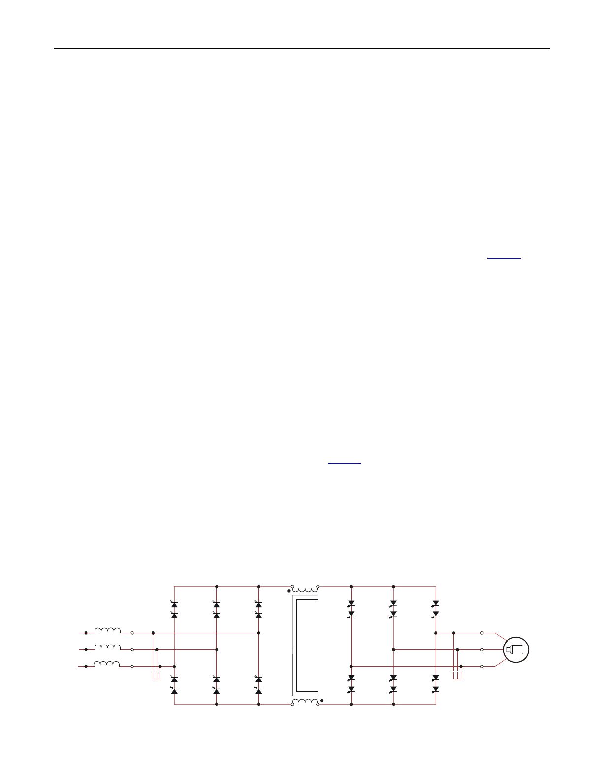
Topology
The PowerFlex 7000L utilizes a Pulse Width Modulated (PWM) – Current
Source Inverter (CSI) for the machine side converter as shown in Figure 1
. This
topology offers a simple, reliable, cost effective power structure that is easy to
apply to a wide voltage and power range. The power semiconductor switches
used are easy-to-series for any medium voltage level. Semiconductor fuses are not
required for the power structure due to the current limiting DC link inductor.
With 6500VPIV rated power semiconductor devices, the number of inverter
components is kept to a minimum. For example, only six inverter switching
devices are required at 2400V, 12 at 3300-4160V, and 18 at 6600V.
The PowerFlex 7000L has the additional benefit of inherent regenerative braking
for applications where the load is overhauling the motor (i.e. downhill conveyors,
etc.), or where high inertia loads (i.e. fans, etc.) need to be slowed down quickly.
Symmetrical Gate Commutated Thyristors (SGCTs) are used for machine
converter switches. Silicon-controlled rectifiers (SCRs) (for 18 Pulse) or SGCTs
(for AFE rectifiers) are used for the line converter switches. An AFE
configuration is shown in Figure 1
.
The PowerFlex 7000L provides a selectable option for enhanced torque control
capabilities and increased dynamic control performance. This High Performance
Torque Control (HPTC) feature delivers 100% torque at zero speed and
provides torque control through zero speed with smooth direction transition.
Figure 1 - AFE Rectifier (4160 Volt)
Rockwell Automation Publication 7000L-UM301D-EN-P - June 2014 17
Page 18
Chapter 1 Overview of Drive
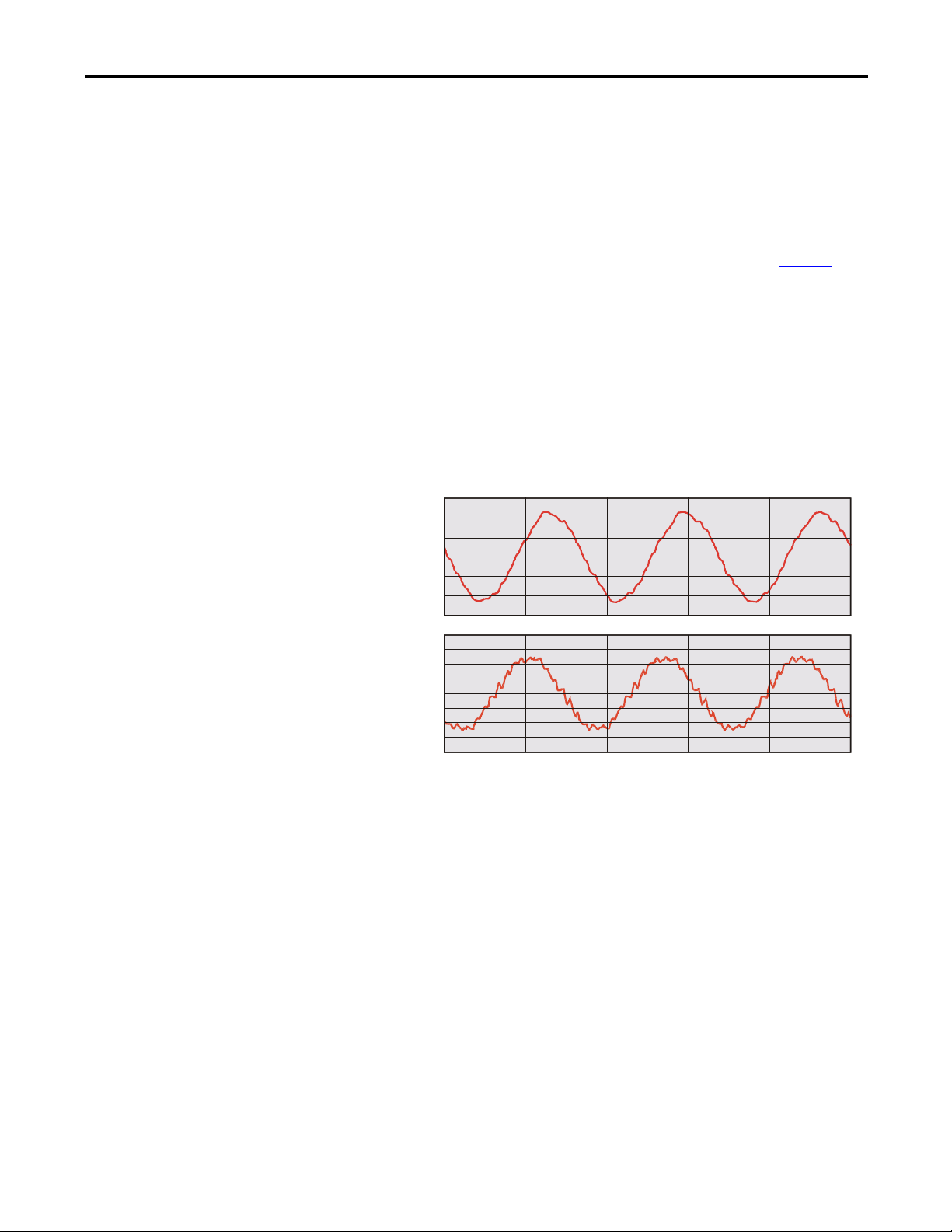
Line
current
Line-to-line
voltage at PCC
Rectifier Designs
There are two offered designs for the rectifier of the PowerFlex 7000L drive.
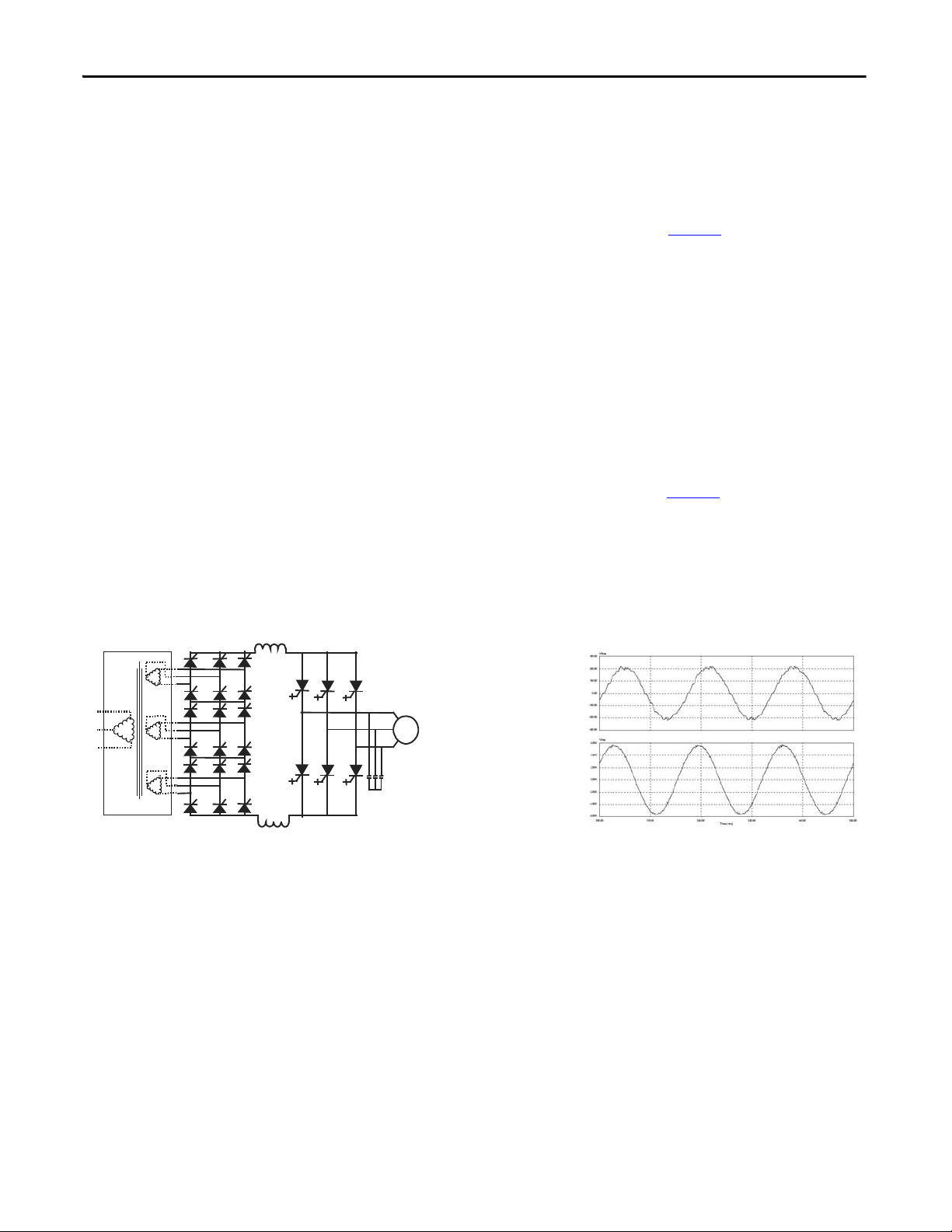
18 Pulse Rectifier
An 18 Pulse phase controlled rectifier is shown in Figure 2. In an 18 Pulse
configuration, the IEEE 519-1992 requirements are met in the majority of cases
without the need for passive filters; however, a multi-winding isolation
transformer is required to mitigate the low order harmonics by phase shifting
principles. The 18 Pulse solution is superior to 6- or 12-pulse offerings in terms of
lowering line side harmonics.
Isolation transformers are available in indoor dry type, cast coil, and outdoor oilfilled designs for maximum flexibility in dealing with floor space, installation
costs, and control room air conditioner loading. (Refer to Specification 80001005, Rectifier Duty Transformers, for more details on transformer requirements
and features.)
Sample line current and voltage are also shown in Figure 2
current is approximately 5.6%, while the THD of line voltage (line-to-line) is
approximately 2.0%. (THD of line voltage is a function of system impedance.)
The 18 Pulse rectifier consists of one master bridge and two slave bridges and will
always have a total of 18 SCR switching devices.
. The THD of line
Figure 2 - 18 Pulse Rectifier and its input waveforms
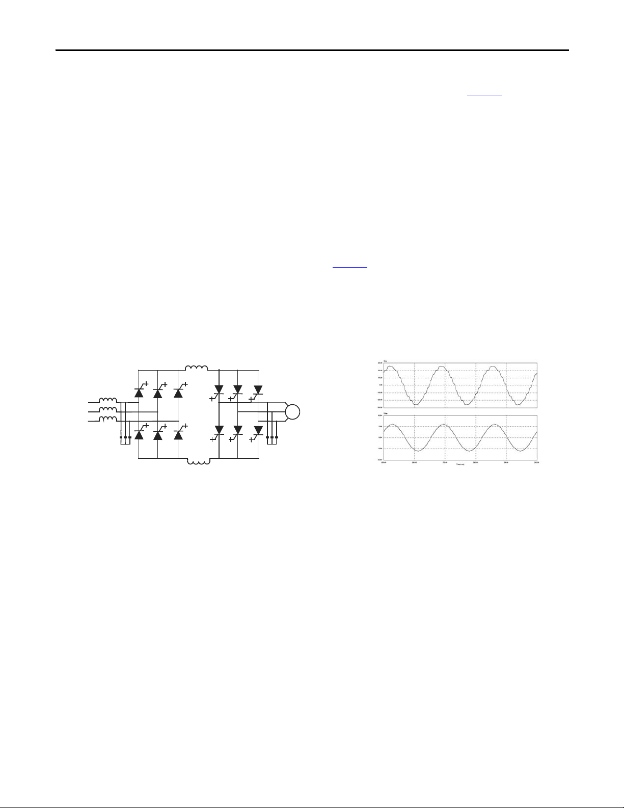
Active Front End (AFE Rectifier)
An active front end (AFE rectifier) suitable for the PowerFlex 7000L topology is
also commonly called a PWM rectifier. This is particularly attractive since it does
not require an isolation transformer to meet IEEE 519-1992. Most available
technologies in today’s MV market require a multi-winding transformer to
mitigate the unwanted harmonics by phase shifting the transformer secondary
windings. Depending on the topology, the transformer can have up to 15 sets of
secondary windings. Elimination of the isolation transformer reduces capital and
installation costs, saves on valuable floor space, and increases overall system
efficiency.
18 Rockwell Automation Publication 7000L-UM301D-EN-P - June 2014
Page 19
Overview of Drive Chapter 1
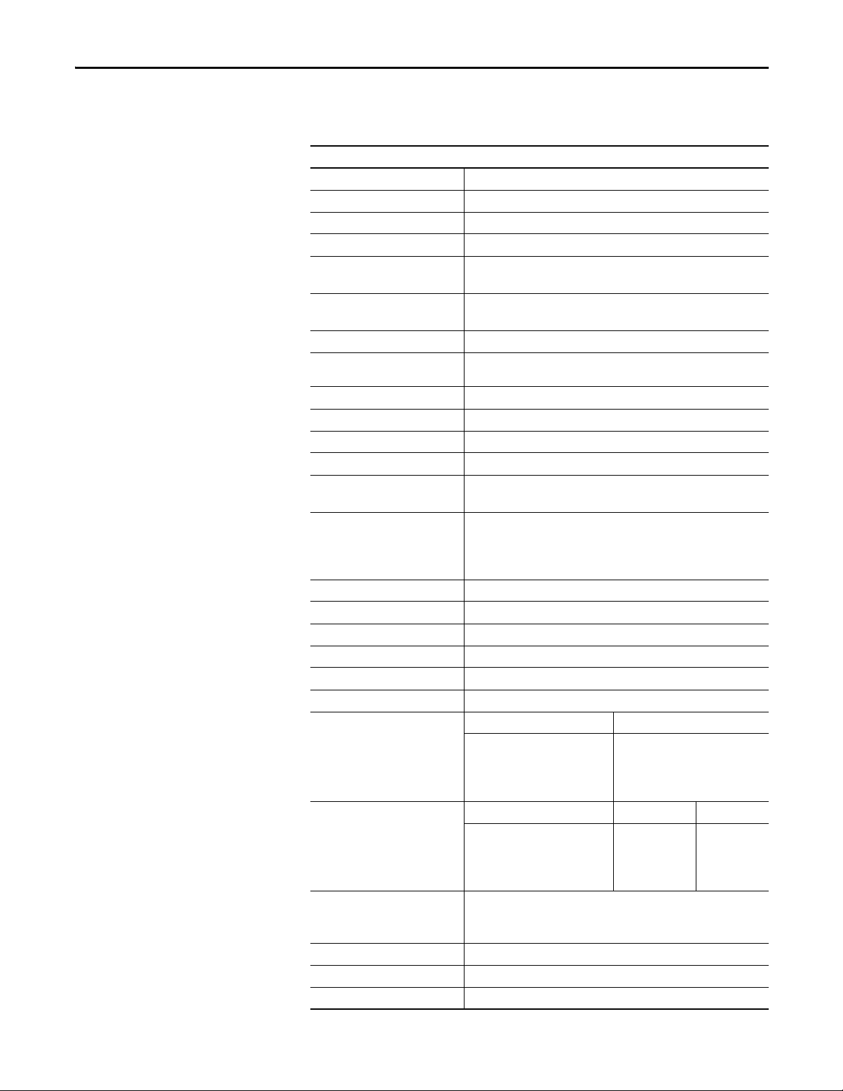
Line
current
Line-to-line
voltage at PCC
The AFE rectifier requires a switching pattern that complies with similar rules as
the inverter. The pattern, used for the example shown in Figure 3
, is a 42-pulse
selective harmonic elimination (SHE) pattern, which eliminates the 5th, 7th and
11th harmonics. The integral input capacitors are designed to reduce the current
harmonics of the higher order. The filter transfer function technique is used to
place the filter break frequency in a region where no harmonics are present. This
prevents the excitation of system harmonic frequencies. Other factors that are
considered when designing the filter are the input power factor and the
requirement on Total Harmonic Distortion (THD) of input current and voltage
waveforms.
The AFE rectifier is ideal when a distribution transformer is required to step
down the distribution voltage to match the VFD and motor voltage. The rectifier
input current, the rectifier terminal voltage and the line current and voltage
waveforms are shown in Figure 3
. The line current THD is approximately 4.5%,
while line-to-line voltage THD is approximately 1.5%. (THD of line voltage is a
function of system impedance.) Input power factor with the AFE rectifier is
equal to or greater than 0.98 for the typical speed and load range when applied to
variable torque loads.
Figure 3 - Active rectifier (PWM) and its input current/voltage waveforms
“Direct-to-Drive” Technology
The PowerFlex 7000L with “Direct-to-Drive” technology allows you to:
• connect supply power directly to the drive without an Isolation
Tr a n s f o r m e r
• connect a new or existing motor directly to the drive without extra motor
filtering.
Most Medium Voltage Drive Manufacturers use multi-winding isolation
transformers to mitigate unwanted harmonics by phase shifting the transformer
secondary windings. Depending on the topology, the transformer can have up to
15 sets of secondary windings. The disadvantages to this method are the high
degree of drive and transformer complexity, a very high component count and
many interconnecting cables and connection points. This leads to much higher
maintenance requirements and lower reliability.
Rockwell Automation Publication 7000L-UM301D-EN-P - June 2014 19
Page 20

Chapter 1 Overview of Drive
Manufacturers also use isolation transformers to protect motors from Common
Mode Voltage stress. When transformers are used they allow the motor neutral
point to be connected to ground, but with this method, the common mode
voltage that would otherwise be impressed on the motor is impressed on the
transformer. The disadvantage to this method is that increased transformer
insulation and increased cable insulation is required between the transformer and
the drive so it can withstand the common mode voltage stress.
Rather than use an Isolation Transformer, the “Direct-to-Drive” Active Front
End uses the semiconductor switching pattern to reduce line current harmonics
to levels that comply to the world’s most accepted harmonic standards. The
Active Front End is the best method of harmonic cancellation because it does not
suffer from complexity and high component count like multi-pulse drive
topologies do.
“Direct-to-Drive” technology produces virtually no common mode voltage so it
is suitable for new or existing motors and imposes no stress on the drive input.
The advantage of “Direct-to-Drive” technology over an Isolation Transformer is
that no extra insulation is required in the motor, in the motor cables or in the line
cables.
In addition to mitigating Common Mode Voltage, “Direct-to-Drive” technology
mitigates dv/dt or Reflected Wave Voltage Stress on motors.
The simplicity of its design results in a lower initial capital investment, lower
operating cost, lower installation cost and lower maintenance cost relative to
drives that require isolation transformers.
The PowerFlex 7000L with “Direct-to-Drive” technology is typically smaller and
lighter than drive technologies that use Isolation Transformers. Isolation
Transformers represent 30 to 50% of a drive system size and 50 to 70% of the
system’s weight. This means that there is no interwiring between drive and
transformer (for external transformer configurations). This makes the PowerFlex
7000L the simplest to install.
20 Rockwell Automation Publication 7000L-UM301D-EN-P - June 2014
Page 21
Overview of Drive Chapter 1
200.00
100.00
0.00
-100.00
-200.00
-300.00
10.00K
7.50K
5.00K
2.50K
0.00K
-2.50K
-5.00K
-7.50K
-10.00K
100.00
110.00
120.00 130.00
)
140.00
150.00
Arms
Vrms
Motor
Current
Motor
Voltage
Motor Compatibility
The PowerFlex 7000L achieves near sinusoidal current and voltage waveforms to
the motor, resulting in no significant additional heating or insulation stress.
Temperature rise in the motor connected to the VFD is typically 3°C (5.5°F)
higher compared to across the line operation. Dv/dt in the voltage waveform is
less than 10 volts / microsecond. The peak voltage that the motor insulation will
see is the rated motor RMS voltage divided by 0.707. Reflected wave and dv/dt
issues often associated with VSI (voltage source inverter) drives are a non-issue
with the PowerFlex 7000L. Typical motor waveforms are shown in Figure 4
.
These motor friendly waveforms are achieved by utilizing a selective harmonic
elimination (SHE) pattern in the inverter to eliminate major order harmonics, in
conjunction with a small output capacitor (integral to the drive) to eliminate
harmonics at higher speeds.
Standard motors are compatible without derating, even on retrofit applications.
Motor cable distance is virtually unlimited. This technology has been tested,
controlling motors up to 15 km (9.3 miles) away from the drive.
Figure 4 - Motor waveforms @ full load, full speed
300.00
TIME (ms
Rockwell Automation Publication 7000L-UM301D-EN-P - June 2014 21
Page 22

Chapter 1 Overview of Drive
SGCT Features and Benefits
An SGCT is a Symmetrical Gate Commutated Thyristor with an integrated gate
drive. Positioning the gate drive close to the SGCT as shown in Figure 5
low inductance path that provides more efficient and uniform gating of the
device. As a result, the device is better suited than a conventional GTO to handle
the fluctuating levels of voltage and current while it is switching on and off during
gating.
An SGCT has similar characteristics to an IGCT (used on some VSI drives),
including low conduction and switching losses, low failure rate, and double sided
cooling for low thermal stress. However, the SGCT achieves voltage blocking
capability in both forward and reverse directions up to 6500 volts by a NPT
(N
on-Punch-Through) structure and nearly symmetrical pnp transistor in the
wafer, while the current is unidirectional. Unlike many VSI topologies that use
IGBTs, the semiconductors used in the PowerFlex 7000L feature a non-rupture,
non-arc failure mode. In the unlikely event of a device failure, the fault would be
contained within the device.
Implementing SGCTs in the PowerFlex 7000L “B” Frame results in significant
advantages including:
1. Simplification of the snubber design and a reduction in the size of the
snubber capacitor by a factor of 10.
, creates a
2. Operation at a higher switching frequency (420-540 Hz), hence reducing
the size of passive components (DC link inductor and motor filter cap) by
50%.
3. Improving performance of the drive.
4. Reduction of component count, hence improving reliability, cost, and size
of the drive.
5. Fail safe failure mode (non-rupture).
Figure 5 - SGCT with integrated gate drive (left) and unit cell structure (right)
22 Rockwell Automation Publication 7000L-UM301D-EN-P - June 2014
Page 23
Specifications
Overview of Drive Chapter 1
Table 1 - General Design Specifications
Description
Motor Type Induction or Synchronous
Input Voltage Rating 2400V, 3300V, 4160V, 6600V
Input Voltage Tolerance ± 10% of Nominal
Volt age Sag
Control Power Loss Ride-through 5 Cycles (Std)
Input Protection
Input Frequency 50/60 Hz, +/- 0.2%
Power Bus Input Short-circuit
Current Withstand (2400…6600V
Basic Impulse Level
Power Bus Design Copper - Tin plated
Ground Bus Copper - Tin plated 6 x 51 mm (¼ x 2 in.)
Customer Control Wire Way Separate and Isolated
Input Power Circuit Protection
Output Voltage 0…2400V
Inverter Design PWM
Inverter Switch SGCT
Inverter Switch Failure Mode Non-rupture, Non-arc
Inverter Switch Failure Rate (FIT) 100 per 1 Billion Hours Operation
Inverter Switch Cooling Double Sided, Low Thermal Stress
Inverter Switching Frequency 420…440 Hz
Number of Inverter SGCTs Voltage SGCTs (per phase)
Inverter PIV Rating
(Peak Inverse Voltage)
Rectifier Designs Direct-to-Drive (transformerless AFE rectifier)
Rectifier Switch SCR (18 Pulse), SGCT (AFE Rectifier)
Rectifier Switch Failure Mode Non-rupture, Non-arc
Rectifier Switch Failure Rate (FIT) 50 (SGCT) 100 (SCR) per 1 Billion Hours Operation
(1)
-30%
> 5 Cycles (Optional UPS)
(2)
Surge Arrestors (AFE/D irect-to-D rive)
Metal Oxide Varistor (MOV) (18 Pulse)
25 kA RMS SYM, 5 Cycle
(3)
)
(4)
45 kV (0…1000 m)
(5)
Vacuum Contactor with Fused Isolating Switch
or Circuit Breaker
0…3300V
0…4160V
0…6000V, 0…6300V, 0…6600V
2400V
3300V
4160V
6600V
2
4
4
6
Voltage PIV (each device) Total PIV
2400V
3300V
4160V
6600V
6500V
6500V
6500V
6500V
AFE with separate isolation transformer
18 Pulse with separate isolation transformer
6500V
13,000V
13,000V
19,500V
Rockwell Automation Publication 7000L-UM301D-EN-P - June 2014 23
Page 24

Chapter 1 Overview of Drive
Table 1 - General Design Specifications (Continued)
Description
Rectifier Switch Cooling Double Sided, Low Thermal Stress
Number of Rectifier Devices per phase Voltage AFE 18 Pu lse
2400V
3300V
4160V
6600V
Output Current THD (1st…49th)< 5%
Output Waveform to Motor Sinusoidal Current / Voltage
Medium Voltage Isolation Fiber Optic
Modulation techniques Selective Harmonic Elimination (SHE)
Synchronous Trapezoidal PWM
Asynchronous or Synchronous SVM (Space Vector Modulation)
Control Method Digital Sensorless Direct Vector
Full Vec tor Control with Encoder Feedback (Option al)
Tuning Method Auto Tuning via Setup Wizard
Speed Regulator Bandwidth 1...10 rad/s with standard control
1...20 rad/s with HPTC (optional)
Torque Regulator Bandwidth 15...50 rad/s with standard control
80...100 rad/s with HPTC (optional)
Torque Accuracy with HPTC (optional) +/- 5%
Speed Regulation
Acceleration/Deceleration Range
Acceleration/Deceleration Ramp
Rates
S Ramp Rate
Critical Speed Avoidance
Stall Protection
Load Los s Detecti on Adjust able level, delay, speed set points
Control Mode Speed or Torque
Current Limit Adjustable in Motoring and Regenerative
Output Frequency Range 0.2...75 Hz (Standard)
Service Duty Rating Normal Duty Heavy Duty
Typical VFD Efficiency > 97.5% (AFE)
Input Power Fac tor AFE Rectifier
0.1% without Encoder Feedback
0.01...0.02% with Encoder Feedback
Independent Accel/Decel – 4 x 30 s
4 x Independent Accel/Decel
Independent Accel/Decel – 2 x 999 s
3 x Independent with Adjustable bandwidth
Adjustable time delay
75 Hz...85Hz (Optional - need specific Motor Filter Capacitor [MFC])
110% Overload for 1 min. every 10
min.
(Variable Torque Load)
> 98% (18 Pulse)
Contact Factory for Guaranteed Efficiency
of Specific Drive Rating
0.95 minimum, 10...100% Load
2
4
4
6
150% Overload for 1 min. every 10
min.
(Consta nt To rque Load)
6
6
6
6
24 Rockwell Automation Publication 7000L-UM301D-EN-P - June 2014
Page 25
Overview of Drive Chapter 1
Table 1 - General Design Specifications (Continued)
Description
IEEE 519 Harmonic Guidelines
VFD Noise Level < 85 dB (A)) per OSHA Standard 3074
Regenerative Braking Capability Inherent – No Additional Hardware or Software Required
Flying Start Capability Yes – Able to Start into and Control a Spinning Load in Forward or Reverse
Operator Interface 10” Color Touchscreen – Cat# 2711P-T10C4A9 (VAC)
Languages English, French, Spanish, Por tuguese, German, Chinese, Italian, Russian, and
Control Power 220/240V or 110/120V, Single phase - 50/60 Hz (20 A)
External I/O 16 Digital Inputs, 16 Digital Outputs
External Input Ratings 50…60 Hz AC or DC
External Output Ratings 50…60 Hz AC or DC
Analog Inputs Three Isolated, 4…20 mA or 0…10V (250 Ω)
Analog Resolution Analog input 12 Bit (4…20 mA)
Analog Outputs One Isolated, Eight Non-isolated,
Communication Interface Ethernet IP/DPI
Scan Time Internal DPI – 2 ms min., 4 ms max.
Communications Protocols
(Opti onal)
Enclosure NEMA 1 (standard) IP21 (IEC)
Lifting Device Standard / Removable
Mounting Arrangement Mounting Sill Channels
Structure Finish Epoxy Powder – Paint
Interlocking Key provision for customer input Disconnecting Device
Corrosion Protection Unpainted Parts (Zinc Plated / Bronze Chromate)
Ambient Temperature 0…40 °C (32…104 °F) / 0…50 °C (32…122 °F) - optional
Fiber Optic Interface Rec tifier – Inverter – Cabinet (Warning / Trip)
Door Filter Painted Defuser with Matted Filter Media
(6)
IEEE 519 - 1992 Compliant
Direction
Built-in PDF viewer
Redesigned PanelView Plus 6 Logic Module with 512 Mb of memory
Polis h
120…240V – 1 mA
30…260V – 1 A
Internal parameter 32 Bit resolution
Serial Communication 16 Bit resolution (.1Hz)
(Digital Speed Reference)
4…20 mA or 0…10V (600 Ω)
DeviceNet ControlNet
Ethernet I/P Lon Works
Dual-port Ethernet I/P Can Open
Profibus RS485 HVAC
Modbus RS485 DF1
Interbus RS232 DF1
USB
NEMA 12 (optional) IP42 (IEC)
Exterior Sandtex Light Grey (RAL 7038) – Black (RAL 8022)
Internal – Control Sub Plates – High Gloss White (RAL 9003)
Rockwell Automation Publication 7000L-UM301D-EN-P - June 2014 25
Page 26

Chapter 1 Overview of Drive
Table 1 - General Design Specifications (Continued)
Description
Door Filter Blockage Air Flow Restriction Trip / Warning
Storage and Transportation
Temperature Range
Relative Humidity Max. 95%, non-condensing
Altitude (Standard) 0…1000 m (0…3300 ft)
Altitude (Optional) 1001…5000 m (0…16,400 ft)
Seismic (UBC Rating) 1, 2, 3, 4
Standards NEMA, IEC, CSA, UL, ANSI, IEEE
(1) Voltage Sag tolerance is reduced to -25% when control power is supplied from medium voltage via CPT.
(2) MOVs are used for 18 Pulse. Surge arrestors are used for AFE/Direct-to-Drive configurations.
(3) Short-circuit fault rating based on input protection device (contactor or circuit breaker).
(4) BIL rating based on altitudes < 1000 m (3300 ft) Refer to factory for derating on altitudes >1000 m.
(5) Optional.
(6) Under certain conditions, power system analysis will be required.
-40…70 °C (-40…185 °F)
26 Rockwell Automation Publication 7000L-UM301D-EN-P - June 2014
Page 27
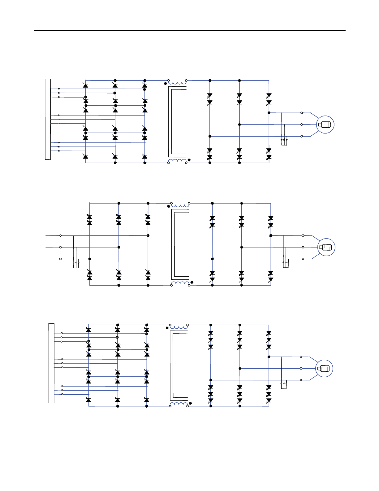
Simplified Electrical Drawings
LINE CONVERTER
L- M-
L+ M+
MACHINE CONVERTER
U (T1)
V (T2)
W (T3)
4U (Z1)
4V (Z2)
4W (Z3)
ISTX
SCRs
3U (Y1)
3V (Y2)
3W (Y3)
2U (X1)
2V (X2)
2W (X3)
SGCTs
LINE CONVERTER
L- M-
L+ M+
MACHINE CONVERTER
U (T1)
V (T2)
W (T3)
4U (Z1)
4V (Z2)
4W (Z3)
ISTX
SCRs
3U (Y1)
3V (Y2)
3W (Y3)
2U (X1)
2V (X2)
2W (X3)
SGCTs
LINE CONVERTER
L- M-
DC LINK
L+ M+
MACHINE CONVERTER
U (T1)
V (T2)
W (T3)
SGCTs
2U (X1)
2V (X2)
2W (X3)
SGCTs
LINE CONVERTER
L- M-
DC LINK
L+ M+
MACHINE CONVERTER
U (T1)
V (T2)
W (T3)
SGCTs
2U (X1)
2V (X2)
2W (X3)
SGCTs
LINE CONVERTER
L- M-
L+ M+
MACHINE CONVERTER
U (T1)
V (T2)
W (T3)
4U (Z1)
4V (Z2)
4W (Z3)
ISTX
SCRs
3U (Y1)
3V (Y2)
3W (Y3)
2U (X1)
2V (X2)
2W (X3)
SGCTs
LINE CONVERTER
L- M-
L+ M+
MACHINE CONVERTER
U (T1)
V (T2)
W (T3)
4U (Z1)
4V (Z2)
4W (Z3)
ISTX
SCRs
3U (Y1)
3V (Y2)
3W (Y3)
2U (X1)
2V (X2)
2W (X3)
SGCTs
Figure 6 - 3300 / 4160 Volt – 18 Pulse
DC LINK
DC LINK
Figure 7 - 3300 / 4160 Volt – Active Front End
Overview of Drive Chapter 1
Figure 8 - 6000-6600 Volt – 18 Pulse
DC LINK
DC LINK
Rockwell Automation Publication 7000L-UM301D-EN-P - June 2014 27
Page 28
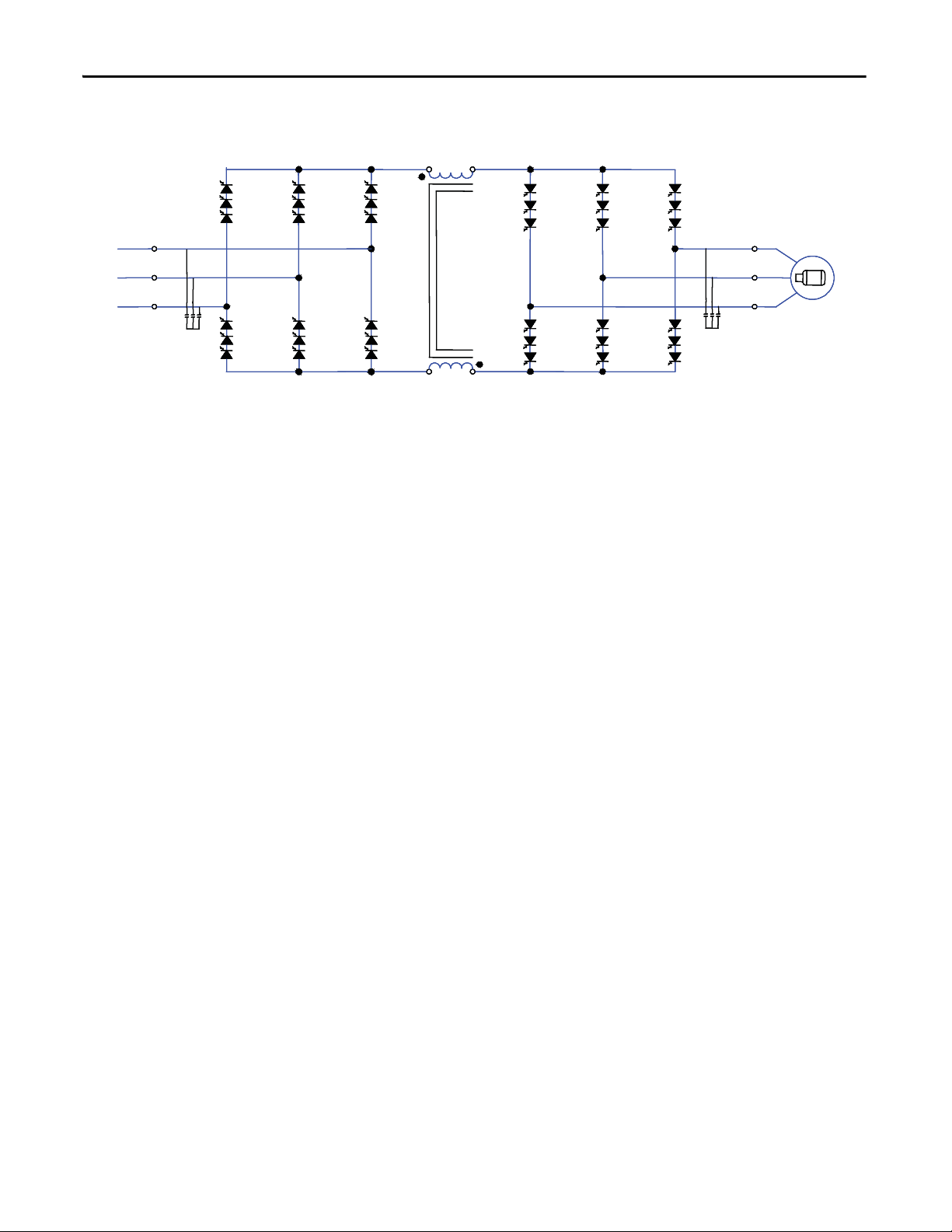
Chapter 1 Overview of Drive
LINE CONVERTER
L- M-
L+ M+
MACHINE CONVERTER
U (T1)
V (T2)
W (T3)
2U (X1)
2V (X2)
2W (X3)
SGCTs
SGCTs
LINE CONVERTER
L- M-
L+ M+
MACHINE CONVERTER
U (T1)
V (T2)
W (T3)
2U (X1)
2V (X2)
2W (X3)
SGCTs
SGCTs
Figure 9 - 6000-6600 Volt – Active Front End
DC LINK
DC LINK
28 Rockwell Automation Publication 7000L-UM301D-EN-P - June 2014
Page 29
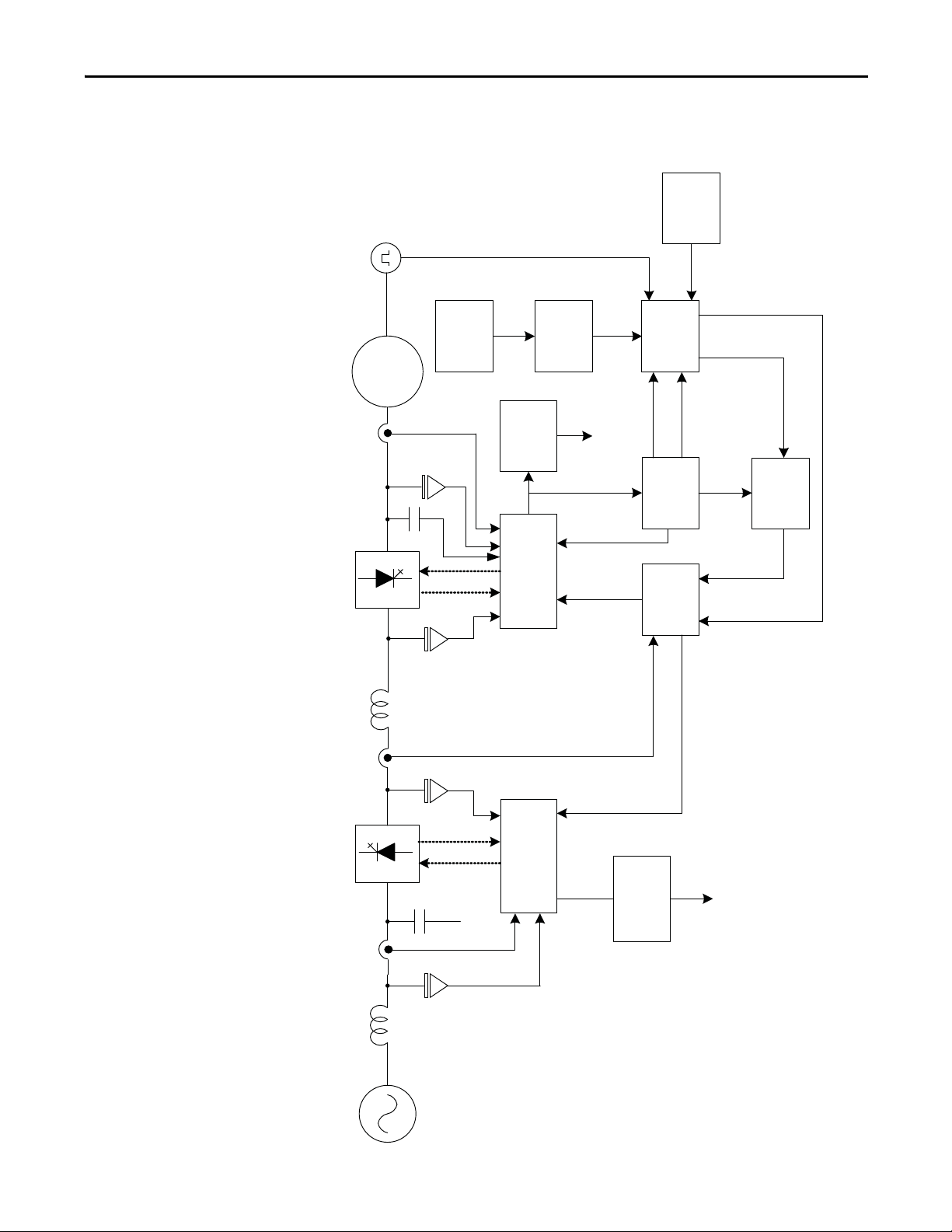
Control Overview
Source
AC Lin e
Reactor
Rectifier
Line Filter
Cap
DC Link
Inductor
Inverter
Line
Curren t
Line Voltage
Line
Protection
Fau lts
Line Side Feedback
and Gating
Alpha
Rectifier
Motor
Filter Cap
Motor
Motor
Curren t
Alpha
Inverter
Current
Control
InvTorque
CurCmd
Inv Flux
CurCmd
Flux
Control
Speed Feedback
Flux Feedback
Motor
Model
Motor
Vol tag e
Machine
Protection
Flux Range
Fau lts
Slip freq
Stator freq
Encoder
Feedback
Speed
Command
Speed
Reference
Speed
Control
Sync
Tra ns fe r
Idc Feedback
Line Side Feedback
and Gating
Figure 10 - PowerFlex 7000L “C” Frame Function Block Diagram
Overview of Drive Chapter 1
Rockwell Automation Publication 7000L-UM301D-EN-P - June 2014 29
Page 30
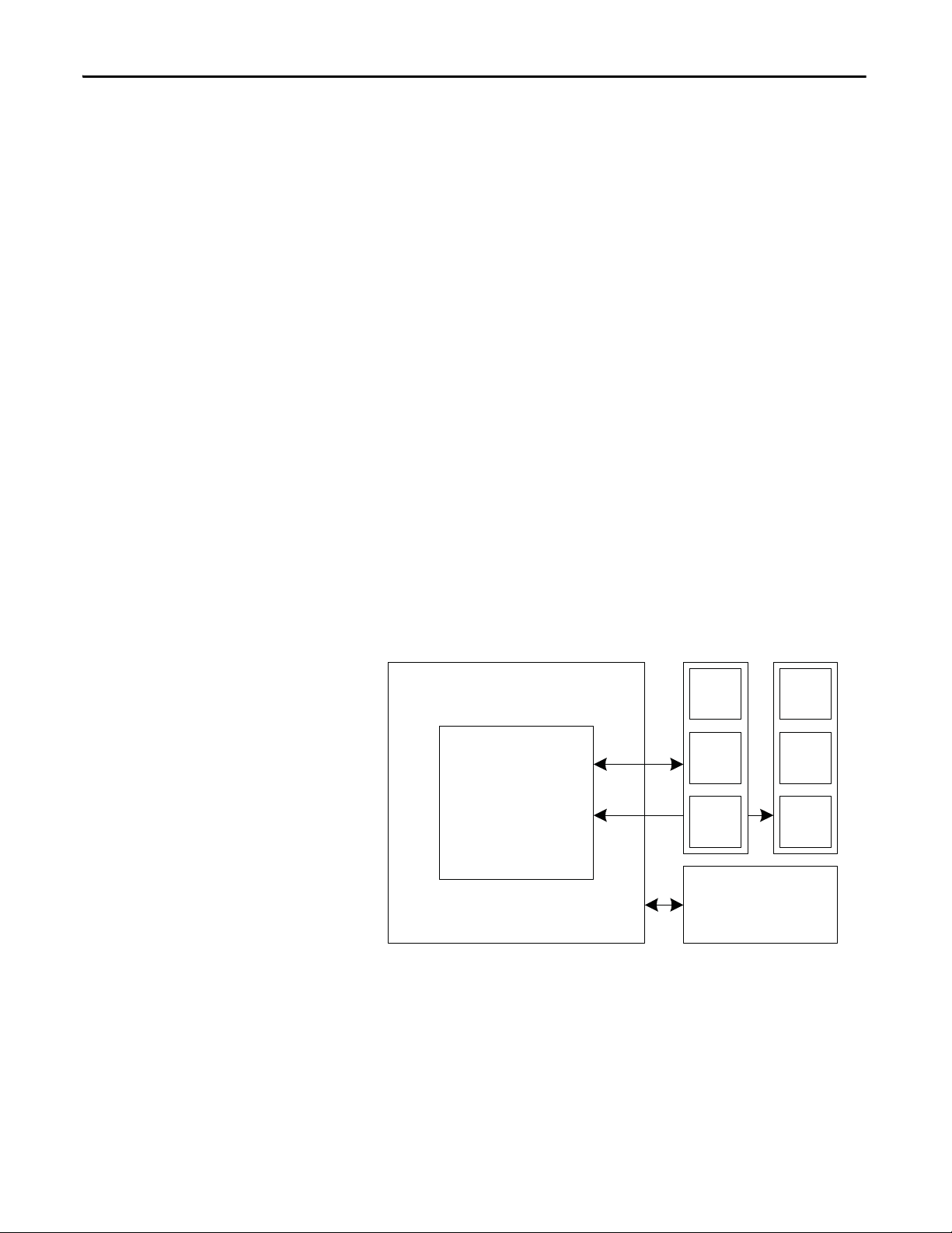
Chapter 1 Overview of Drive
ACB
DPM
XIO
OIB
OIB
OIB
OIB
OIB
OIB
ACB – Analog Conditioning Board
DPM – Drive Processor Module
OIBB – Optical Interface Base Board
XIO – External Input/Output
OIB – Optical Interface Board
Direct Vector Control
Control Hardware
The method of control in the PowerFlex 7000 “C” Frame medium voltage AC
drive is called sensorless direct vector control, meaning that the stator current is
divided into torque producing and flux producing components, allowing the
motor torque to be changed quickly without affecting motor flux. This method
of control is used without encoder feedback for applications requiring
continuous operation above 6 Hz and less than 100% starting torque.
Full vector control can also be achieved with encoder feedback for applications
requiring continuous operation down to 0.2 Hz with up to 150% starting torque.
Vector control offers superior performance over volts/hertz type drives. The
speed bandwidth range is 5...25 rad/s, while the torque bandwidth range is
15...50 rad/s.
The control hardware includes a processor board (DPM) with an interface to six
fiber optic boards (depending on the voltage and number of switching devices)
via OIBB, an analog conditioning board (ACB) and an external IO board (XIO).
The control hardware is used for rectifier and inverter, induction or synchronous
drive control and the two rectifier types (18 Pulse or Active Front End).
The DPM features two floating point DSPs (Digital Signal Processor) and a
FPGA (Field Programmable Gate Array) for advanced functions such as gating
and diagnostics, fault handling and drive synchronization control.
Figure 11 - Control Hardware Layout for PowerFlex 7000 “C” Frame
OIBB OIBB
30 Rockwell Automation Publication 7000L-UM301D-EN-P - June 2014
Page 31

Overview of Drive Chapter 1
Operator Interface
Figure 12 - PowerFlex 7000L Operator interface terminal
The operator interface terminal features a 16-line, 40-character, pixel based LCD
display that makes text and graphics easy to read. Bar chart meters are
configurable for common process variables including speed, voltage and load.
Everything is user friendly about the PowerFlex 7000L operator interface
terminal including the greeting on the opening screen. The terminal is designed
for the greatest ease of use for start-up, monitoring and troubleshooting. The
setup wizard helps the user to set the required parameter menus by asking
questions or prompting selections for desired operation. Warnings and comments
appear complete with help text to keep the user on the right track. The setup
wizard combined with the auto-tuning feature allows the drive to be tuned to the
motor and load as quickly and accurately as possible, resulting in fast start-ups,
smooth operation, and less down time.
Up to five test modes are available including low voltage gate check, and running
at full current without motor connected.
Enhanced diagnostic functions are available on the operator interface terminal
including separate fault and warning queues in non-volatile RAM (NVRAM),
extended fault text strings and on line help, and trend buffers for 16 variables.
Rockwell Automation Publication 7000L-UM301D-EN-P - June 2014 31
Page 32

Chapter 1 Overview of Drive
Notes:
32 Rockwell Automation Publication 7000L-UM301D-EN-P - June 2014
Page 33

Drive Installation
IMPORTANT
Chapter 2
Safety and Codes
Unpacking and Inspection
WARNING: The Canadian Electrical Code (CEC), National Electrical Code (NEC),
or local codes outline provisions for safely installing electrical equipment.
Installation MUST comply with specifications regarding wire type, conductor
sizes, branch circuit protection and disconnect devices. Failure to do so may
result in personal injury and/or equipment damage.
Before leaving the factory, all drives have been tested both mechanically and
electrically. Immediately upon receiving the drive, remove the packing and check
for possible shipping damage. Report any damage immediately to the claims
office of the common carrier.
After unpacking the material, check the item(s) received against the bill of lading
to assure that the nameplate description of each item agrees with the material
ordered. Inspect the PowerFlex 7000 drive for physical damage, as stated in the
Rockwell Automation Conditions of Sale.
All claims for breakage and damage whether concealed or obvious must be
made to the carrier by the Customer as soon as possible after receipt of the
shipment. Rockwell Automation will be glad to give the Customer reasonable
assistance in the securing of adjustment for such damage claims.
Transportation and Handling
Remove all packing material, wedges, or braces from within the drive. Operate
the contactors and relays manually to assure that they operate freely. If any part of
the equipment will not be installed when it is unpacked, it should be stored in a
clean, dry place. The storage temperature must be between -40°C (-40°F) and
70°C (185°F) with a maximum humidity of 95%, non-condensing, to guard
against damage to temperature sensitive components in the controller.
The PowerFlex 7000 drive is shipped on a wooden skid, which is bolted to the
underside of the cabinetry. The drive should remain bolted to the shipping skid
until it is delivered to its final installation area. Lifting angles are supplied bolted
to the top of the cabinetry. The drive must be kept in an upright position during
any handling. Refer to General Handling Procedures, publication 7000-IN002_EN-P for a more detailed description.
The drive must be transported on a pallet or via use of the lifting beam supplied
as part of all 2300 mm (91 in.) high cabinets.
Rockwell Automation Publication 7000L-UM301D-EN-P - June 2014 33
Page 34

Chapter 2 Drive Installation
IMPORTANT
ATT EN TI ON : Ensure that the load rating of the lifting device is sufficient to
safely raise the controller sections. Refer to the packing slip enclosed with
shipment for shipping weights.
Round rollers can be used to assist in moving the drive to the installation site.
Once at the final site, the pipe rolling technique can be used to place the cabinet
in the desired position.
f
WARNING: Care must be exercised when using either a forklift or the pipe
rolling technique for positioning purposes to ensure that the equipment is not
scratched, dented or damaged in any manner. Always exercise care to stabilize
the drive during handling to guard against tipping and injury to personnel.
It is extremely important that the customer’s installation duties are
performed correctly. Any errors will cause damage to the Drive and
delays in commissioning.
Never attempt to lift or move the drive by any means other than the methods
listed, as structural damage or personal injury could result. The following
methods of handling are recommended:
Overhead Lifting
1. Attach rigging to the lifting angles on the top of the cabinetry.
ATTENTION: Ensure that the load rating of the lifting device and
rigging is sufficient to safely raise the drive. Refer to shipping weights
on the packing slip enclosed with the shipment.
2. Do not pass ropes or cables through the support holes in the lifting angles.
Use slings with safety hooks or shackles.
3. Select or adjust the rigging lengths to compensate for an unequal weight
distribution of load and maintain the drive in an upright position.
4. To reduce the tension on the rigging and the compressive load on the
lifting device, do not allow the angle between the lifting cables/chains and
vertical to exceed 45 degrees.
ATTENTION: Drives may contain heavy equipment that could be
adversely affected by tilting.
34 Rockwell Automation Publication 7000L-UM301D-EN-P - June 2014
Page 35

Figure 13 - Overhead Lifting
(50.8 mm x 152.4 mm)
Drive Installation Chapter 2
Rod or Pipe Rollers
This method is only suitable when there are no inclines and the drive is being
moved on one floor level.
1. Boards 50.8 mm x 152.4 mm (2 in. x 6 in.) or equivalent and at least 300
mm (12 inches) longer than the drive must be placed under the shipping
skid.
2. Carefully ease the shipping platform over the roller pipes until the drive
weight is borne on the roller pipes.
3. The drive can be rolled to its designated location. Steady the load to
prevent tipping.
Figure 14 - Rod or Pipe Rollers
Rockwell Automation Publication 7000L-UM301D-EN-P - June 2014 35
Page 36

Chapter 2 Drive Installation
Fork Lift Trucks
A single fork lift truck may be used on drives not exceeding 3 m (120 inches) in
length if the lift truck has sufficient lifting capacity. Larger drives can be moved
with two forklift trucks operating in tandem.
1. Insert forks into openings of shipping skids from the rear of the drive.
2. Carefully balance the drive on the forks because the drives are usually
heavier at one side.
3. Use safety straps when handling to steady the drive while moving.
Storage
If it is necessary to store the drive, be certain to store in a clean dry dust free area.
Storage temperature should be maintained between -40°C (-40°F) and 70°C
(185°F). If storage temperature fluctuates or if humidity exceeds 85%, space
heaters should be used to prevent condensation. The drive should be stored in a
heated building having adequate air circulation. The drive must never be stored
outdoors.
Siting of the Drive
Site Considerations
The standard environment in which the equipment is designed to operate is:
• Elevation above sea level less than 1000 meters (3250 feet)
• Ambient air temperature between 0°C (32°F) and 40°C (104°F)
• Relative humidity of the air not to exceed 95% non-condensing
For the equipment to operate in conditions other than those specified consult the
local Rockwell Automation Sales office.
The equipment requires the following site conditions:
(A) Indoor installation only, no dripping water or other fluids
(B) Clean air for cooling requirements
(C) Level floor for anchoring the equipment. Refer to dimension drawings for
the location of the anchoring points.
(D) The room in which the equipment is located must allow for full opening of
the doors of the equipment, typically 1200 mm (48 inches). Also,
allowances have to be made for clearance for fan removal. This fan
allowance must be greater than 700 mm (27.5 inches).
or
36 Rockwell Automation Publication 7000L-UM301D-EN-P - June 2014
Page 37

Drive Installation Chapter 2
Dimension drawings can be obtained by contacting the local Rockwell
Automation Sales office. The equipment does not require rear access for
servicing.
(E) Allowance must be made for the stream of cooling air which exits the drive
at the top. The flow of cooling air into and out the drive must be kept clear
and uninhibited.
(F) The room in which the equipment is located must be large enough to
accommodate the thermal losses of the equipment since air conditioning
may be required; the ambient temperature must not exceed that for which
the equipment is rated. The heat created by the drive is directly
proportional to the power of the motor being driven and the efficiency of
equipment within the room. If thermal load data is required contact the
Rockwell Automation Sales office.
(G) The area in which the drive is located should be free of radio frequency
interference such as encountered with some welding units. This may cause
erroneous fault conditions and shut down the drive.
(H) The equipment must be kept clean. Dust in the equipment decreases
system reliability and inhibits cooling.
Installation
(I) Power cable lengths to the motor are virtually unlimited due to the near
sinusoidal voltage and current waveforms. Unlike voltage source drives,
there are no capacitive coupling, dv/dt, or peak voltage issues that can
damage the motor insulation system. The CSI-PWM topology utilized in
the PowerFlex 7000 medium voltage AC drive has been tested with
motors located up to 15 km (9.3 miles) from the drive.
(J) Only personnel familiar with the function of the drive should have access
to the equipment.
(K) The drive is designed for front access and should be installed with
adequate and safe clearance to allow for total door opening. The back of
the unit may be placed against a wall although some customers prefer back
access also. If back access is desired, set drive 300 mm (12 inches) out from
wall.
.
ATTENTION: An incorrectly applied or installed drive can result in
component damage or a reduction in product life. Ambient conditions
not within the specified ranges may result in malfunction of the drive.
When the drive has been placed at its installation area, the lag bolts that fasten
the shipping skid to the drive must be removed. The drive is moved off the
shipping skid and the shipping skid can be discarded.
Position the drive in its desired location. Verify that the drive is on a level surface
and that the position of the drive will be vertical when the anchor bolts are
installed.
Rockwell Automation Publication 7000L-UM301D-EN-P - June 2014 37
Page 38

Chapter 2 Drive Installation
LR
CAB
1
CABLE
CAB
2
CONV
CAB
3
CAP
CAB
4
CAP
CAB
5
DC LINK
CHOKE
CAB
6
PUMP
CAB
7
Wood Skid
1st SECTION
2nd SECTION
The location of the anchor points is provided with the dimension drawing of the
drive.
Install and tighten the anchor bolts. (M12 or 1/2" hardware required).
Engineered bolt systems are required for seismic requirements. Consult factory.
Remove the top lifting angles, retain the hardware.
Install the hardware from the lifting angles in the tapped holes at the top of drive;
this prevents leakage of cooling air as well as keeping dust out of the equipment.
Joining Shipping Splits
The Drive may have been shipped in two or more shipping sections which are to
be connected at installation. It is essential that the surfaces are level. Arrange the
sections per the information provided in the dimension drawings and move the
sections together. Ground bus, power and control connections are to be made per
the electrical diagrams provided. Side sheets of the enclosures are to be joined
with thread forming screws using the available holes.
Liquid-cooled Drives may require joining of the coolant pipes. Some enclosure
ratings may require the addition of silicone sealant where cabinets join together
to prevent the possible ingress of dripping water.
For Direct-to-Drive liquid-cooled 6600V Drives (430A, 495A and 575A rated
current) the Drive will be shipped in two sections as shown in Figure 15
Figure 15 - Typical Split Drive
LiftingAngles
.
The 1st section consists of 5 cabinets.
The 2nd section consists of 2 cabinets.
Final placement requires that the 1st and 2nd sections are joined at final
installation site.
38 Rockwell Automation Publication 7000L-UM301D-EN-P - June 2014
Page 39

Drive Installation Chapter 2
WARNING: Heavy Magnetic DC Link Chokes up to 4600 kg (10,000 lb) are
shipped inside DC Link Choke cabinet. Professional Millwright/Rigging
contractors are required for safe final placement of Drive sections.
Connect the Sections
Field connect the following:
• CPVC pipe splices – 2 pieces
• Power Bus Splice Kit – 4 pieces
• Ground Bus Splice – 1 piece
• Control Wiring
Tools Required (not supplied)
• Adjustable or socket wrenches for 6-, 10-, 12-mm and 5/8" bolt and nut
hardware
• Strap wrench for tightening CPVC unions
• Screwdriver assortment
• Cable ties
• Wire cutters
Install CPVC Piping Splices
• Open doors of capacitor cabinet (Cabinet #5) next to DC Link Choke
cabinet (Cabinet #6). Refer to Figure 16
• Remove capacitor from position #3, if installed (not all configurations
have a capacitor in this location). It is not necessary to remove capacitor
from position #2.
.
ATTENTION: Capacitors weigh up to 100 kg (220 lb). Use two people to
remove the unit from the structure.
Rockwell Automation Publication 7000L-UM301D-EN-P - June 2014 39
Page 40

Chapter 2 Drive Installation
Capacitor
Position #1
Capacitor
Position #2
Capacitor
Position #3
CPVC Pipe
Splices
Figure 16 - Capacitor Cabinet
• Remove CPVC pipe splices shipped in the capacitor cabinet. Install and
tighten the 4 CPVC unions with strap wrench (1/4 to 1/2 turn past hand
tight). Ensure O-ring is seated inside male end of union. Refer to
Figure 17
, Figure 18 and Figure 19. Do not use CPVC primer or cement.
40 Rockwell Automation Publication 7000L-UM301D-EN-P - June 2014
Page 41

Figure 17 - CPVC Pipe Splices (Capacitor #2 not shown for clarity)
Pipe Splice #1
Capacitor
Cabinet
DC Link
Choke Cabinet
Pipe Splice #2
Drive Installation Chapter 2
Figure 18 - Typical Strap Wrench (not supplied) used to tighten unions on CPVC pipe splices
Rockwell Automation Publication 7000L-UM301D-EN-P - June 2014 41
Page 42

Chapter 2 Drive Installation
TIP
Figure 19 - Capacitor Cabinet and DC Link Choke Cabinet after Pipe Splices installed
Install according to flow direction labels as shown.
Connect Power: M+, L+, M-, L- Power Bus
• Locate the four (4) Power Bus pieces of the splice kit in DC Link Choke
cabinet and remove shipping wrapping. See Figure 20
• Connect Power Bus M+, L+, M-, L- on the red insulators in the DC Link
Choke cabinet and mating bus pieces in the capacitor cabinet. Hardware
required is pre-attached to bus connections, cabling, and insulators in the
cabinet where the power bus splice kit will attach. Remove and attach as
shown in Figure 20
to Figure 24.
• Torque M10 carriage bolts connecting bus to bus in the capacitor cabinet
to 29 Nm (21 ft-lb). Torque M12 hardware supplied for cable to bus stab
connections to 50 Nm (37 ft-lb).
• After cable connections have been made, ensure cable connections to
choke stabs are torqued to 50 Nm (37 ft-lb).
• Ensure a minimum of 3" (75mm) clearance exists between Medium
Voltage Bus field connections (including hardware) and all cabinet
sidesheets.
.
42 Rockwell Automation Publication 7000L-UM301D-EN-P - June 2014
Page 43

Figure 20 - DC Link Choke Cabinet
MV Bus (4 pieces)
Ground Bus Link (1 piece)
Inside DC Link Choke Cabinet
Power Bus (4) pieces; Ground bus (1) shipped disassembled
Drive Installation Chapter 2
Figure 21 - DC Link Choke Cabinet before field power bus connections
Rockwell Automation Publication 7000L-UM301D-EN-P - June 2014 43
Page 44

Chapter 2 Drive Installation
M-
M+
L+
L-
M+
L+
L-
M-
Figure 22 - DC Link Choke Cabinet after field connections of power bus
Figure 23 - Capacitor Cabinet after field connections of power bus
44 Rockwell Automation Publication 7000L-UM301D-EN-P - June 2014
Page 45

Figure 24 - Capacitor Cabinet
(Connect left side of Medium Voltage bus pieces with M10 hardware)
Drive Installation Chapter 2
• Connect cables from DC Link Choke to MV Bus pieces using supplied
M12 hardware.
Figure 25 - DC Link Choke Cabinet after connection of cables from DC Link Choke to red insulators
• Connection points are labeled on bus and DC Link Choke. Connect
cables from labeled stabs M+, L+, L-, L+ on DC Link Choke to
corresponding labeled stabs M+, L+, M-, L+ on bus.
Rockwell Automation Publication 7000L-UM301D-EN-P - June 2014 45
Page 46

Chapter 2 Drive Installation
Figure 26 - DC Link Choke Cabinet Typical Cable Connection
• Connect Ground Bus Link from top left of DC Link Choke cabinet to
ground bus in adjacent capacitor cabinet by sliding underneath wire duct.
Use supplied hardware.
Figure 27 - Ground Bus Link
Figure 28 - Install Ground Bus Link
46 Rockwell Automation Publication 7000L-UM301D-EN-P - June 2014
Page 47

Figure 29 - Ground Bus Connection Points
(Install Ground Bus Link using Supplied Hardware)
Drive Installation Chapter 2
Control Wiring Connections
Refer to EDs and wiring diagrams supplied with Drive. Contact Rockwell
Automation representative for assistance. Final wiring connections to be
performed by Rockwell Automation field service representative.
1. Remove the wireway covers located on top of the line and motor filter
capacitor sections and the DC Link section.
2. If drive has strip heater wiring, it will be coiled up in the top wireway.
Route these wires down through the grommeted cutout for connection on
the terminal blocks located in the upper left side of the capacitor section.
Figure 30 - Strip heater terminal block
Rockwell Automation Publication 7000L-UM301D-EN-P - June 2014 47
Page 48

Chapter 2 Drive Installation
3. Route the control wiring which has been coiled up and left hanging in the
upper area of the motor filter capacitor section, back up through the two
grommeted cutouts back into the wireway. There is a fiber optic cable in
this bundle and care must be taken not to damage it. The fiber optic cable,
control power wires and the “XIO link” cable will be required in the pump
control cabinet.
Figure 31 - Control Wiring
4. Route the 8 gauge black and red twisted pairs of wire and the Belden
shielded cables down through the grommeted cutout into the AC\DC
power supply section.
Figure 32 - Belden Shielded Cables
48 Rockwell Automation Publication 7000L-UM301D-EN-P - June 2014
Page 49

Drive Installation Chapter 2
5. Route the 3-fan control wires, 2 cabinet over-temperature control wires
down through the grommeted cutout into the center of the DC choke
section (Figure 33
Figure 33 - Fan Thermostat Control Wires
).
6. Route the control wires down through the grommeted cutout into the
control power disconnect section (Figure 34
).
7. Connect the numbered wires to the corresponding numbered terminal
blocks (Figure 35
Figure 34 - Route control wires through grommeted cutout
to Figure 38).
Rockwell Automation Publication 7000L-UM301D-EN-P - June 2014 49
Page 50

Chapter 2 Drive Installation
8. Refer to the electrical drawing and make the above control wiring
connections.
Figure 35 - 56V DC Connections
Figure 36 - AC DC fails Belden Cable Connection
50 Rockwell Automation Publication 7000L-UM301D-EN-P - June 2014
Page 51

Figure 37 - Control Wire Power Connections
Drive Installation Chapter 2
Figure 38 - Thermostat and Fan Connections
9. Once all the connections have been made and neatly routed in each
section, the excess control wires can be looped up in the top wireways.
10. Swing out the control section in the pump control cabinet.
11. Route the XIO link cable, control power wires and the fiber optic cable
down through the wire ways grommeted cutout.
12. Route the XIO link cable, the control power wires into the pump control
cabinet through the upper side grommeted cutout.
Rockwell Automation Publication 7000L-UM301D-EN-P - June 2014 51
Page 52

Chapter 2 Drive Installation
13. Route the fiber optic cable into the pump control cabinet through the
lower side grommeted cutout.
Figure 39 - 120V and XIO cables through upper cutout
14. Connect the XIO link cable to the XIO board “XIO link A” connector.
(Figure 40
)
15. Connect the control power wires to the control power terminal blocks.
Refer to Electrical Drawings for corresponding wire numbers and terminal
blocks.
16. Connect the fiber optic cable to the TFB board.
Figure 40 - XIO link Cable
52 Rockwell Automation Publication 7000L-UM301D-EN-P - June 2014
Page 53

Figure 41 - TFB Fiber Optic connected
Silicone
sealant
Drive Installation Chapter 2
• Use supplied silicone (see Figure 42) to seal between cabinets to prevent
moisture or dirt from entering. Join sidesheets with M6 Taptite thread
forming screws in holes provided.
Figure 42 - Capacitor Cabinet
Rockwell Automation Publication 7000L-UM301D-EN-P - June 2014 53
Page 54

Chapter 2 Drive Installation
Remove cotter pins
Removal of DC Link Choke Turnbuckle Supports
Remove turnbuckles which attach choke to top lifting angle pair as follows:
• Remove cotter pins (see Figure 43
Carefully remove turnbuckles. Retain for future use.
Figure 43 - Choke Cabinet
) from bottom turnbuckle jaw then top.
• Re-install any capacitors that were removed.
• Proceed with Removal of Lifting Angles.
Removal of Lifting Angles
Lifting angles should be removed only when the Drive is in its final location. The
lifting angles are retained with 5/8"-11 hardware. The 5/8" bolts need to be reinstalled in their holes in the top of the Drive to prevent the ingress of foreign
matter into the enclosures. See Figure 44
.
54 Rockwell Automation Publication 7000L-UM301D-EN-P - June 2014
Page 55

Figure 44 - Insert bolts
Drive Installation Chapter 2
ATT EN TI ON : Refer to the technical drawings and installation manual for your
Drive mounting instructions. Failure to correctly anchor the cabinet may result
in damage to the equipment or injury to personnel. Contact the area Rockwell
Automation sales office if you do not have these documents.
Shock Indication Labels
Shock indication labels are devices that permanently record the physical shock to
which equipment is subjected.
At the time of final preparation for shipment from the factory, a shock indication
label is installed on the inside door of the converter cabinet.
During the shipping and installation process drives may inadvertently be
subjected to excess shock and vibration which may impair its functionality.
When the drive has been placed in its installation area, the converter door is to be
opened and the shock indication labels inspected.
The drive is shipped with a label that records shock levels in excess of 10G. If
these shock levels have been attained, the chevron shaped window will appear
blue in one of the two windows.
If these shock levels have been attained, record the values. There is a greater
possibility of the drive having sustained internal damage if it has been subjected
to physical shock during the shipping and installation process.
Even if the indicators show that no shock was attained, full inspection and
verification in accordance with the Commissioning process outlined in Chapter
4 is still essential.
Rockwell Automation Publication 7000L-UM301D-EN-P - June 2014 55
Page 56

Chapter 2 Drive Installation
TIP
Red Plastic Housing
Window Area appears Blue
if subjected to shock
51 mm
(2.0)
21 mm (0.8)
Figure 45 - Shock Indicator
Installation of Exhaust Air Hood
Even though this is a liquid-cooled drive, some sections still require air
circulation.
On the top of the cabinets with cooling fans, sheet metal exhaust hoods are to be
installed. The components to make up the exhaust hood have been packaged and
shipped with the drive and are to be found in the control/cabling cabinet.
The first step is to remove the protective plate covering the fan opening on the
drive. It is a flat cover plate bolted to the top plate. Remove the bolts and plate
and set aside for reuse.
Secondly, loosely assemble the two L-shaped panel components shipped with the
drive.
For AFE Rectifiers with a line reactor cabinet, there may be a provision for small
fans in the roof of the cabinet. This cabinet will still have a full-size exhaust air
hood.
Locate the exhaust hood on top of the cabinet per Figure 46
original cover plate previously set aside. (Care must be taken that the notches on
the bottom flange are oriented toward the sides of the drive). Affix assembly to
the drive top plate. Tighten all hardware.
ATT EN TI ON : Any screws that are accidentally dropped in the equipment must
be retrieved as damage or injury may occur.
and re-install the
56 Rockwell Automation Publication 7000L-UM301D-EN-P - June 2014
Page 57

Drive Installation Chapter 2
Fan Hood to be installed on site
Internally mounted fans
Internally mounted fans
Capacitor cabinets have internally mounted fans which are installed and wired by
Rockwell Automation (refer to Figure 46
fan hood.
Figure 46 - Fan Hood Installation (Internally Mounted Fans)
). The customer only needs to install the
Rockwell Automation Publication 7000L-UM301D-EN-P - June 2014 57
Page 58
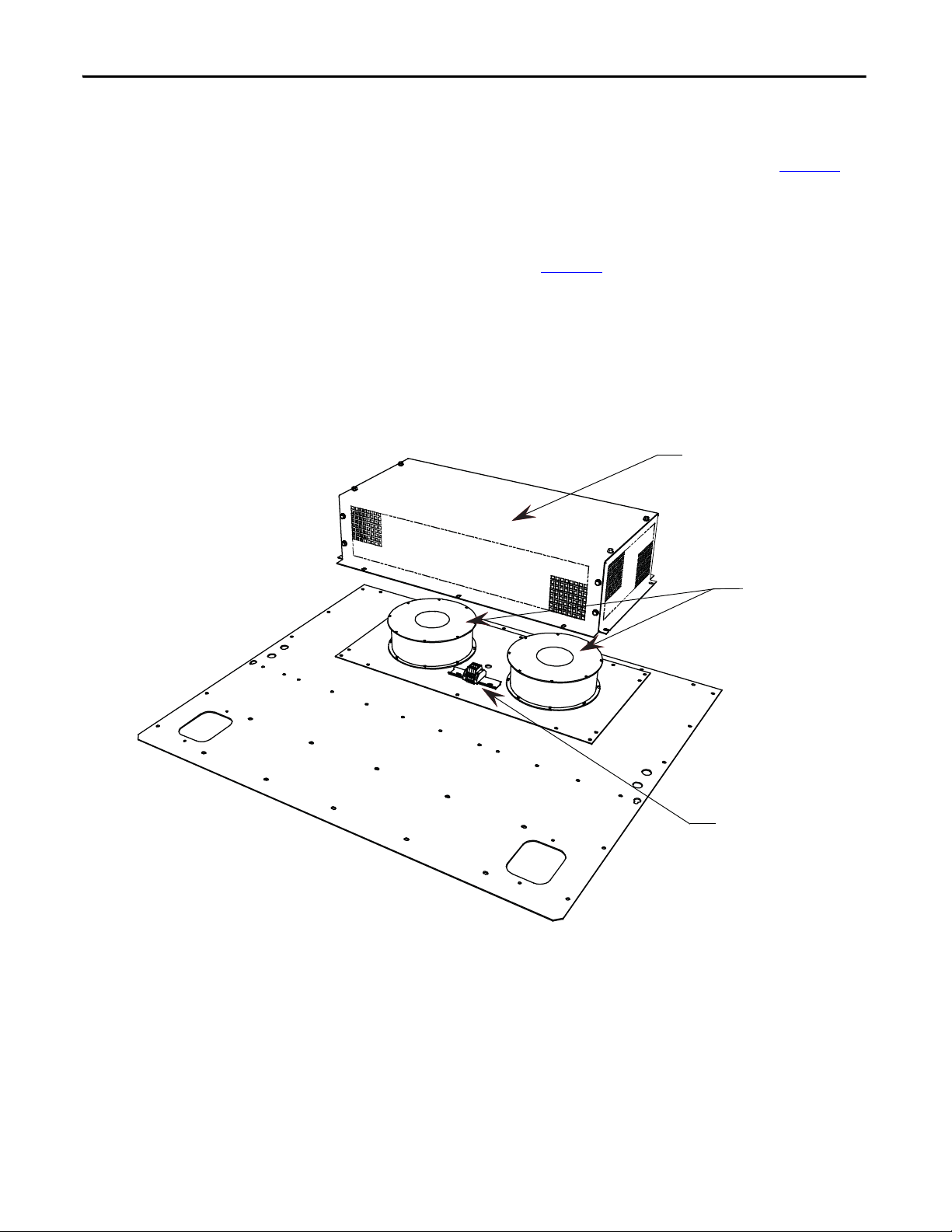
Chapter 2 Drive Installation
Fan Hood
External fans
Terminal blocks
Externally mounted fans and fan hood
The converter has cooling fans that are externally mounted (refer to Figure 47). It
is necessary to re-install and connect the fans, and install the fan hood.
Shipped with the drive is a plate with the fans mounted and wired to terminal
blocks. On site, the fan assembly is to be mounted on the top plate of the
converter cabinet as shown in Figure 47
Wiring for fan power is to be routed through the hole near the terminal blocks.
The plate is fastened to the cabinet with M6 hardware. Connect wires to the
terminal blocks per the electrical diagram.
Position the fan hood over the fan assembly and fasten with M6 hardware.
Figure 47 - Fan Hood Installation (Externally Mounted Fans and Fan Hood)
.
58 Rockwell Automation Publication 7000L-UM301D-EN-P - June 2014
Page 59
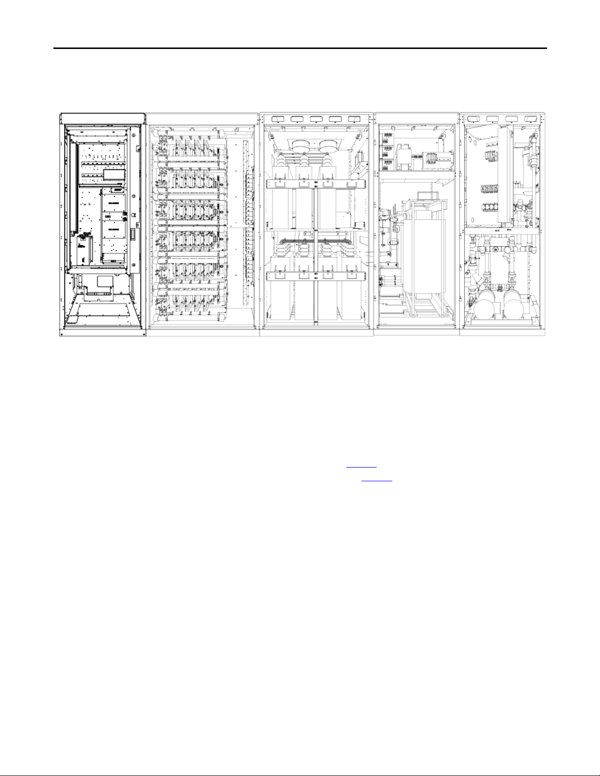
Typical PowerFlex 7000L Drive Structure Layout
Control and
Cabling Cabinet
Converter Cabinet
Capacitor Cabinet
DC Link Inductor
Cabinet
Pump Cabinet
TIP
Figure 48 - Typical PowerFlex 7000 “C” Frame Drive Structure Layout
Drive Installation Chapter 2
Control/Cabling Cabinet
Major Components
Shows the medium voltage area located in the control/cabling cabinet behind the
low voltage compartment and with barriers removed.
The control/cabling cabinet comes in two different configurations:
• AFE rectifier (Figure 49
• 18 Pulse rectifier (Figure 50
)
)
The following seven diagrams show the typical layout of each cabinet for
PowerFlex 7000 “C” Frame Drives.
Rockwell Automation Publication 7000L-UM301D-EN-P - June 2014 59
Page 60

Chapter 2 Drive Installation
Hall-effect Sensor
Motor Terminals
Line Terminals
Volt age Sens ing
Hall-effect Sensor
Surge Arrestors
Curren t
Transformer
Figure 49 - Control and Cabling Cabinet (AFE Rectifier version shown) (with Control Panel
removed)
60 Rockwell Automation Publication 7000L-UM301D-EN-P - June 2014
Page 61
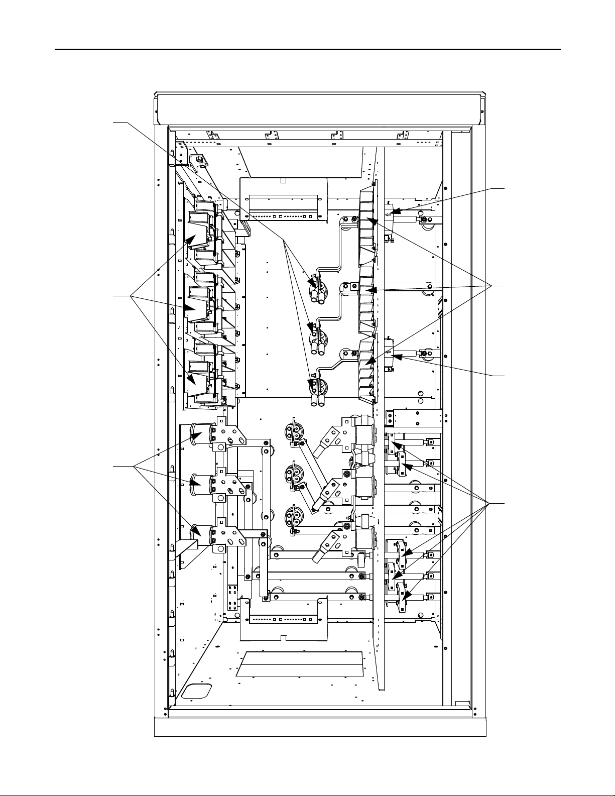
Curren t
Tra ns fo rm er s
Voltage Sensing
Hall Effect Sensor
Hall Effect Sensor
Line Terminals
Tra ns ie nt
Suppression
Networks
Motor Terminals
Drive Installation Chapter 2
Figure 50 - Control and Cabling Cabinet (18 Pulse version shown) (with Control Panel removed)
Rockwell Automation Publication 7000L-UM301D-EN-P - June 2014 61
Page 62
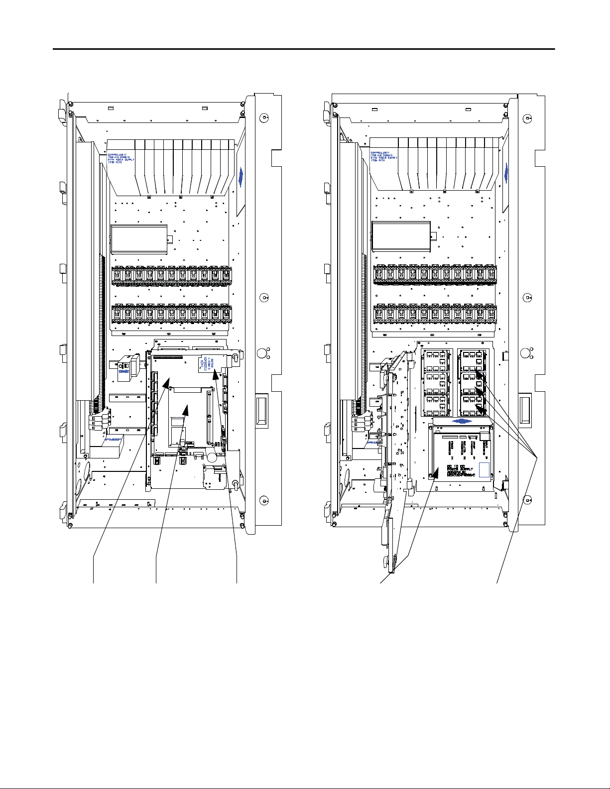
Chapter 2 Drive Installation
ANALOG
CONTROL
BOARD
Analog Control Board Drive Processor
Module (DPM)
Tach Feedback
Circuit Board
DC/DC Power Supply Fiber Optic Interface Boards
Figure 51 - Low Voltage Tub Compartment
62 Rockwell Automation Publication 7000L-UM301D-EN-P - June 2014
Page 63
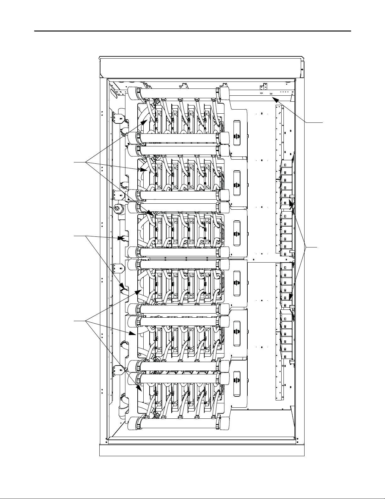
Ground Bus
Isolated Gate Drive
Power Supplies
(IGDPS)
Inverter Modules
Rectifier Modules
Coolant Piping
Drive Installation Chapter 2
Figure 52 - Converter Cabinet Components (4160V AFE shown)
Rockwell Automation Publication 7000L-UM301D-EN-P - June 2014 63
Page 64

Isolated Gate
Driver Power
Supplies (IGDPS)
Ground Bus
Inverter Modules
Rectifier Modules
Chapter 2 Drive Installation
Figure 53 - Converter Cabinet Components (6600V AFE shown)
64 Rockwell Automation Publication 7000L-UM301D-EN-P - June 2014
Page 65
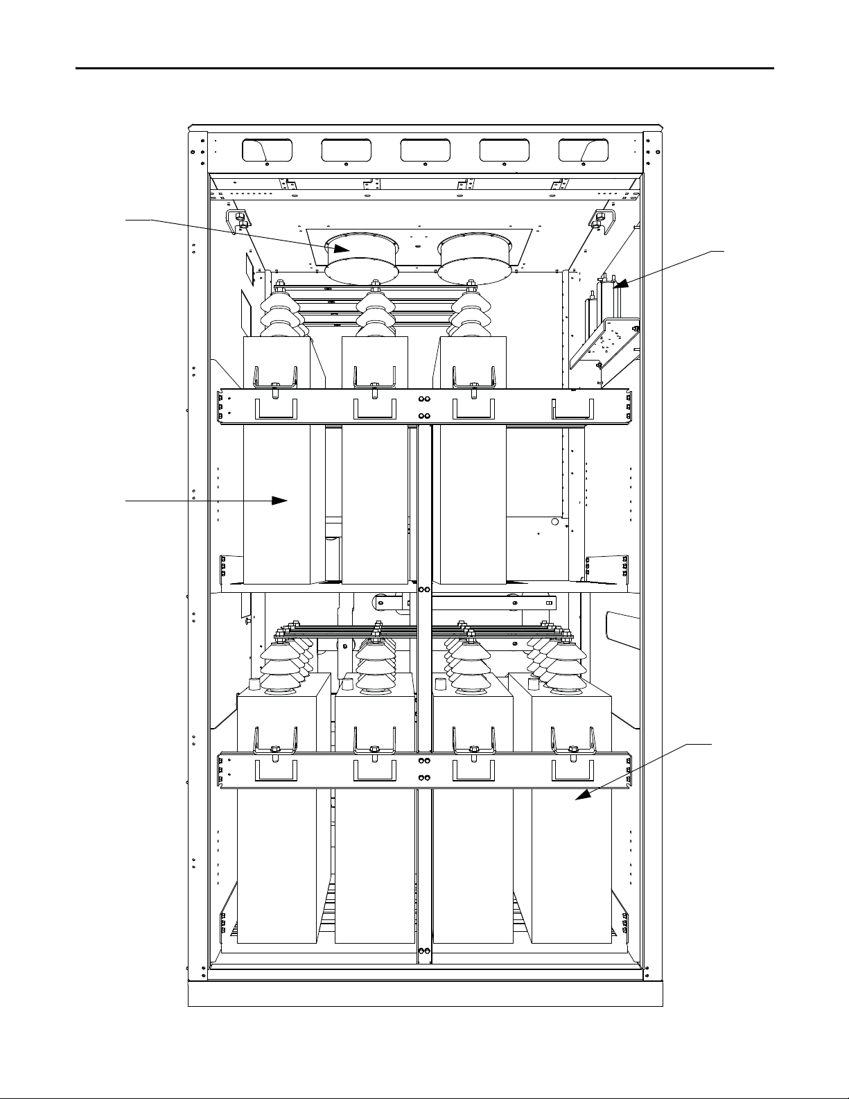
Grounding
Network
Line Capacitors
Motor Line
Capacitors
Cooling Fan
Drive Installation Chapter 2
Figure 54 - Capacitor Cabinet
Rockwell Automation Publication 7000L-UM301D-EN-P - June 2014 65
Page 66

Chapter 2 Drive Installation
Liquid-cooled
DC Link Reacotr
Fuse Blocks
Power
Transformer
AC/DC Power
Supplies
Cooling Pipes
Figure 55 - DC Link Inductor Cabinet
66 Rockwell Automation Publication 7000L-UM301D-EN-P - June 2014
Page 67

Figure 56 - Pump Cabinet (showing swing-out low voltage panel)
Coolant Pumps
Deioni zer CartridgePumping Panel
Swingou t Low Voltage Panel
Drive Installation Chapter 2
Rockwell Automation Publication 7000L-UM301D-EN-P - June 2014 67
Page 68

Chapter 2 Drive Installation
IEC Component and Device Designation
PowerFlex 7000 electrical drawings use conventions that are based on IEC
(International Electrotechnical Commission) standards, while remaining
basically compatible with North American ANSI (American National Standards
Institute) standards. The symbols used to identify components on the drawings
are international and a full listing of the symbols is given as part of each
PowerFlex 7000 elementary drawing (ED) set. The device designations used on
the drawings and labeling are also listed with explanations on each drawing set.
Wiring identification uses a source/destination wire number convention on point
to point multi-conductor wiring and in situations where the system is warranted.
The wire-numbering system of unique, single numbers for multi-drop and point
to point wiring continues to be used for general control and power wiring.
Wiring that connects between the sheets or that ends at one point and starts at
another point on a drawing has an arrow and drawing reference to indicate the
ongoing connection. The drawing reference indicates the sheet and the X/Y
coordinates of the continuation point. The reference system is explained on a
sheet in each drawing set. The unique wire numbering system serves as
confirmation that the correct wire is being traced from sheet to sheet or across a
drawing. Wires in multi-conductor cables are typically identified by color rather
than by number. The abbreviations used to identify the colors on the drawings
are fully identified on a sheet in the drawing set.
Power Wiring Selection
The following tables identify general wire selections that will be encountered
when installing the PowerFlex 7000 drive line-up.
General Notes
Adherence to the following recommended field power cabling insulation levels
for medium voltage drives will help to ensure trouble-free start-up and operation.
The cable insulation level must be increased over that which would be supplied
for an across-the-line application with the same rated line-to-line voltage.
Either shielded or unshielded cable may be used based on the criteria considered
by the distribution system designer and local standards. However, NEC requires
shielded cable for installations above 2 kV.
68 Rockwell Automation Publication 7000L-UM301D-EN-P - June 2014
Page 69

Drive Installation Chapter 2
Cable Insulation
The cable insulation requirements for the PowerFlex 7000 drive are given in the
tables below.
ATT EN TI ON : Voltage ratings shown in the following tables are peak line-toground. Some cable manufacturers rate voltage line-to-line RMS. Ensure the
cable meets the rating specified in the following tables.
Table 2 - Cable Insulation Requirements for 18 Pulse and 6P / AFE Drives with Isolation
Tra nsfor mer
System Voltage (V, RMS) Cable Insulation Rating (kV) (Maximum Peak Line-to-Ground)
Line Side Machine Side
2400 ≥4.1 ≥2.2
3000 ≥5.12 ≥2.75
3300 ≥5.63 ≥3.0
4160 ≥7.1 ≥3.8
6000 ≥10.8 ≥5.5
6300 ≥11.4 ≥5.8
6600 ≥11.8 ≥6.0
Table 3 - Cable Insulation Requirements for “Direct-to-Drive” Technology
System Voltage (V, RMS) Cable Insulation Rating (kV) (Maximum Peak Line-to-Ground)
Line Side Machine Side
2400 ≥2.2 ≥2.2
3000 ≥2.75 ≥2.75
3300 ≥3.0 ≥3.0
4160 ≥3.8 ≥3.8
6000 ≥5.5 ≥5.5
6300 ≥5.8 ≥5.8
6600 ≥6.0 ≥6.0
The following table identifies general wire categories that will be encountered
when installing the PowerFlex 7000 Drive. Each category has an associated wire
group number that is used in the following sections to identify the wire to be
used. Application and signal examples along with the recommended type of cable
for each group are provided. A matrix providing the recommended minimum
spacing between different wire groups run in the same tray or separate conduit is
also provided.
Rockwell Automation Publication 7000L-UM301D-EN-P - June 2014 69
Page 70

Chapter 2 Drive Installation
Wire
Category
Wire
Group
Application Signal Example Recommended
Power 1 AC Power
(> 600V AC)
2AC Power
(TO 600V AC)
Control 3 115V AC
or 115V DC
424V AC
or 24V DC
Signal 5 Analog Signals
DC Supplies
(Low Speed)
6 Digital
(High Speed)
Logic
115V AC
Power
Logic
Digital
Table 4 - Wire Group Numbers
2.3 kV, 3Ø
AC Lines
480V, 3Ø Per IEC / NEC
Relay Logic
PLC I/O
Power Sup plies
Instruments
PLC I/O Per IEC / NEC
5-24V DC
Supplies
Power Sup plies
TTL Log ic Level
Pulse Train
Input Tachometer
PLC
Communications
Per IEC / NEC
Local Codes and
Application
Requirements
Local Codes and
Application
Requirements
Per IEC / NEC
Local Codes and
Application
Requirements
Local Codes and
Application
Requirements
Belden 8760
Belden 8770
Belden 9460
Belden 8760
Belden 9460
Belden 9463
Cable
For Tray: Recommended spacing between different wire groups in the same tray.
For Conduit: Recommended spacing for wire groups in separate conduit – mm (inches)
Wire
Group
In Tray 228.6
Between
Condui t
In Tray 228.6
Between
Condui t
In Tray 228.6
Between
Condui t
In Tray 228.6
Between
Power1Power2Control3Control4Signal5Signal
6
(9.00)
228.6
(9.00)
228.6
(9.00)
228.6
(9.00)
76.2 (3.00)
Between Conduit
(9.00)
228.6
(9.00)
152.4
(6.00)
152.4
(6.00)
76.2 (3.00)
Between Conduit
(9.00)
152.4
(6.00)
228.6
(9.00)
152.4
(6.00)
76.2 (3.00)
Between Conduit
(9.00)
152.4
(6.00)
152.4
(6.00)
228.6
(9.00)
76.2 (3.00) Between Conduit
Condui t
All signal wiring must be run in separate steel conduit.
A wire tray is not suitable.
The minimum spacing between conduits containing different
wire groups is 76.2 mm (3 inches).
Belden 8760 - 18 AWG, twisted pair, shielded
Belden 8770 - 18 AWG, 3 conductor, shielded
Belden 9460 - 18 AWG, twisted pair, shielded
Belden 9463 - 24 AWG, twisted pair, shielded
Note 1: Steel conduit or cable tray may be used for all PowerFlex 7000 Drive power or control wiring, and steel conduit is required for all
PowerFlex 7000 Drive signal wiring. All input and output power wiring, control wiring or conduit should be brought through the
drive conduit entry holes of the enclosure. Use appropriate connectors to maintain the environmental rating of the enclosure. The
steel conduit is REQUIRED for all control and signal circuits, when the drive is installed in European Union countries. The connection
of the conduit to the enclosure shall be on full 360 degree and the ground bond at the junction shall be less than 0.1 ohms. In EU
countries this is a usual practice to install the control and signal wiring.
Note 2: Spacing between wire groups is the recommended minimum for parallel runs of 61 m (200 feet) or less.
Note 3: The customer is responsible for the grounding of shields. On drives shipped after November 28/02, the shields are removed from
the drive boards. On drives shipped prior to November 28/02, all shields are connected at the drive end and these connections must
be removed before grounding the shield at the customer end of the cable. Shields for cables from one enclosure to another must be
grounded only at the source end cabinet. If splicing of shielded cables is required, the shield must remain continuous and insulated
from ground.
Note 4: AC and DC circuits must be run in separate conduits or trays.
Note 5: Voltage drop in motor leads may adversely affect motor starting and running performance. Installation and application
requirements may dictate that larger wire sizes than indicated in IEC / NEC guidelines are used.
70 Rockwell Automation Publication 7000L-UM301D-EN-P - June 2014
Page 71

Drive Installation Chapter 2
The wire sizes must be selected individually, observing all applicable safety and
CEC or IEC / NEC regulations. The minimum permissible wire size does not
necessarily result in the best operating economy. The minimum recommended
size for the wires between the drive and the motor is the same as that used if a
main voltage source connection to the motor was used. The distance between the
drive and motor may affect the size of the conductors used.
Consult the wiring diagrams and appropriate CEC or IEC / NEC regulations to
determine correct power wiring. If assistance is needed, contact your local
Rockwell Automation Sales Office.
Power Cabling Access
The drive is built with provision for either the top or bottom power cable entry.
Cable access plates are provided on the top and bottom plates of the connection
cabinet identified by the customer specific dimension drawing.
Access the Customer Power Cable Terminations:
• Open the door of the low voltage control compartment. The low voltage
control compartment is hinged on its left side. The power terminals are
behind the low voltage control compartment.
• Note that there is a key interlock to prevent swinging the low voltage
control compartment open unless the medium voltage source is locked
out.
• Turn each of the three latches on the right side of the low voltage
compartment one-quarter turn using an 8-mm hexagonal key wrench.
There is a pull handle provided on the right side of the low voltage
compartment.
• Slowly pull the handle so that the low voltage compartment swings out.
The power terminals are now visible.
• The installer is responsible for modifying the power cable access plates to
suit the requirements.
• Note that appropriate connectors must be used to maintain the
environmental rating of the enclosure.
Rockwell Automation Publication 7000L-UM301D-EN-P - June 2014 71
Page 72

Chapter 2 Drive Installation
Latch
Key Interlo ck
Handle
Terminal Blocks Customer (TBC)
Figure 57 - Swing-out of Low Voltage Compartment
72 Rockwell Automation Publication 7000L-UM301D-EN-P - June 2014
Page 73
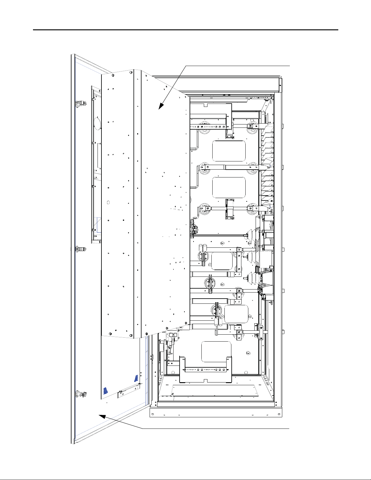
Figure 58 - Access to Power Terminals
Low Voltage Door
Low Voltag e
Compartment (Open)
Drive Installation Chapter 2
Rockwell Automation Publication 7000L-UM301D-EN-P - June 2014 73
Page 74

Chapter 2 Drive Installation
Power Connections
The installer must ensure that interlocking with the upstream power source has
been installed and is functioning.
The installer is responsible for ensuring that power connections are made to the
equipment in accordance with local electrical codes.
The drive is supplied with provision for cable lugs. The power terminals are
identified as follows:
Incoming Connections
• Drives with AFE Rectifiers: 2U, 2V, 2W
• Drives with 18 Pulse Rectifiers
– Secondary (d0) 2U, 2V, 2W
– Secondary (d-20) 3U, 3V, 3W
– Secondary (d+20) 4U, 4V, 4W
• Motor Connections U, V, W
The installer is responsible for ensuring that power connections are made with
appropriate torque. (Refer to Torque Requirements for Threaded Fasteners
page 419 (Appendix B).)
on
The drive is supplied with provision for grounding of cable shields and stress
cones near the power terminals.
74 Rockwell Automation Publication 7000L-UM301D-EN-P - June 2014
Page 75
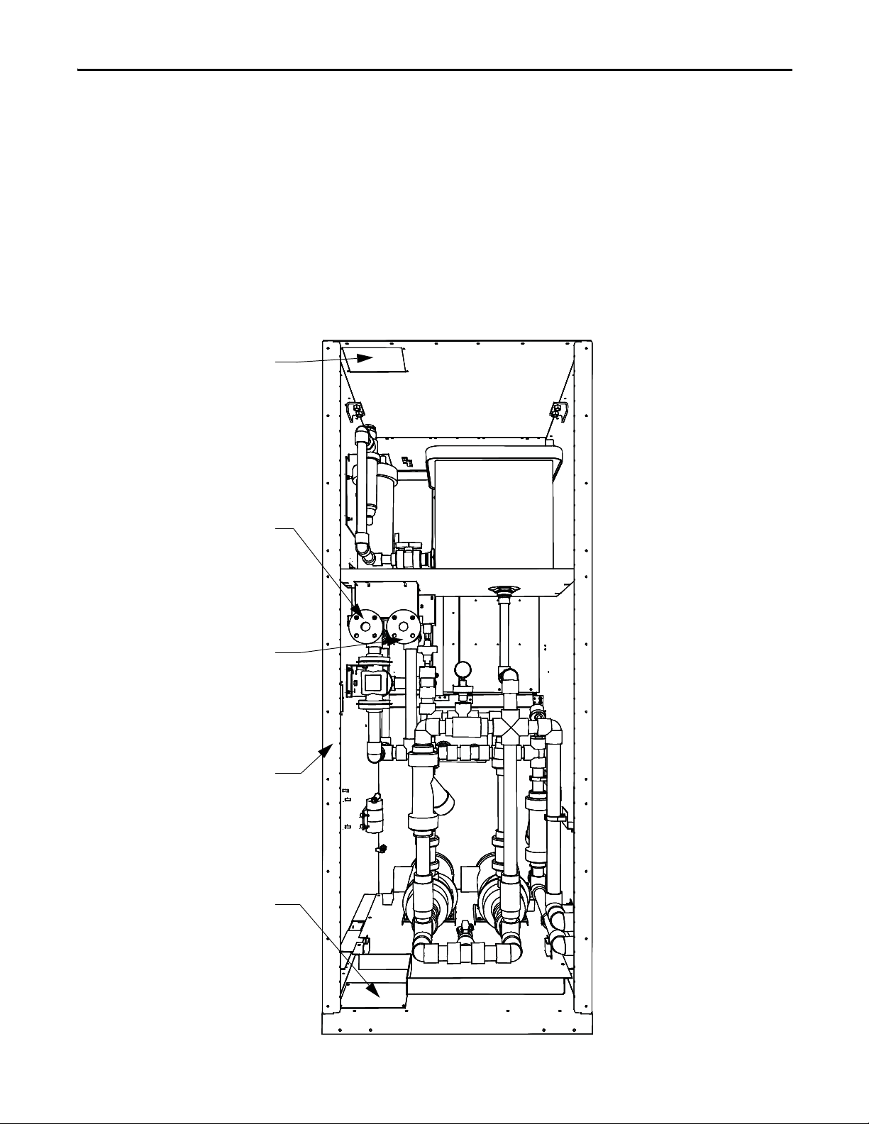
Drive Installation Chapter 2
Piping to Heat Exchanger
through top of cabinet
Outlet Coolant Connection
Warm Fluid to Heat Echaanger
Inlet Coolant Connection
Fluid Return from heat Exchanger
Piping to Heat Exchanger
Routing through right side of cabinet
Piping to Heat Exchanger
Routing through bottom of cabinet
Liquid Connections
Liquid-to-Air Heat Exchangers
There are three options for routing piping between the liquid-to-air heat
exchanger and the pumping cabinet of the drive:
• Pipes through top plate of cabinet
• Pipes through bottom plate of cabinet
• Pipes through right side of cabinet
Removable plates are provided in each of these locations.
Figure 59 - Connection to Liquid-to-Air Heat Exchanger
(rear of pumping cabinet shown with back plates removed)
Rockwell Automation Publication 7000L-UM301D-EN-P - June 2014 75
Page 76

Chapter 2 Drive Installation
Pump Section
Fluid Cooler
Pipe Materials and Layout
All material that contacts fluid between the heat exchanger and drive must be
either Schedule 80 CPVC or stainless steel. Rockwell Automation recommends
using stainless steels AISI 304L or 316L to connect the drives to heat exchangers.
Use 304L and 316L welding wire to avoid sensitization of the welded material.
Sensitization due to incorrect welding causes localized corrosion of the welded
area. Pressures expected within a drive are below 75 psi with test pressures of
110 psi.
Schedule 80 CPVC piping may be installed within a climate controlled building
with any outside pipe of stainless steel. Shield CPVC from direct sunlight to
prevent UV damage. Use expansion loops for long pipe runs.
See document CTS-3 "CPVC CTS Products Design and Installation Manual"
from Spears Manufacturing Company (www.spearsmfg.com
) for more
information.
Figure 60 - Plan View of Piping to Heat Exchanger (Piping may vary with exchanger)
Ensure exit flow from the pump cabinet is routed to the inlet flange of the
exchanger.
The estimated flow rate and pressure is printed on the cooling system schematic,
which is posted on the inside of the pumping cabinet door.
The pipes to which connections are made are Schedule 80 CPVC: 38 mm
(1.50 in.) or 50 mm (2.00 in.).
76 Rockwell Automation Publication 7000L-UM301D-EN-P - June 2014
Page 77
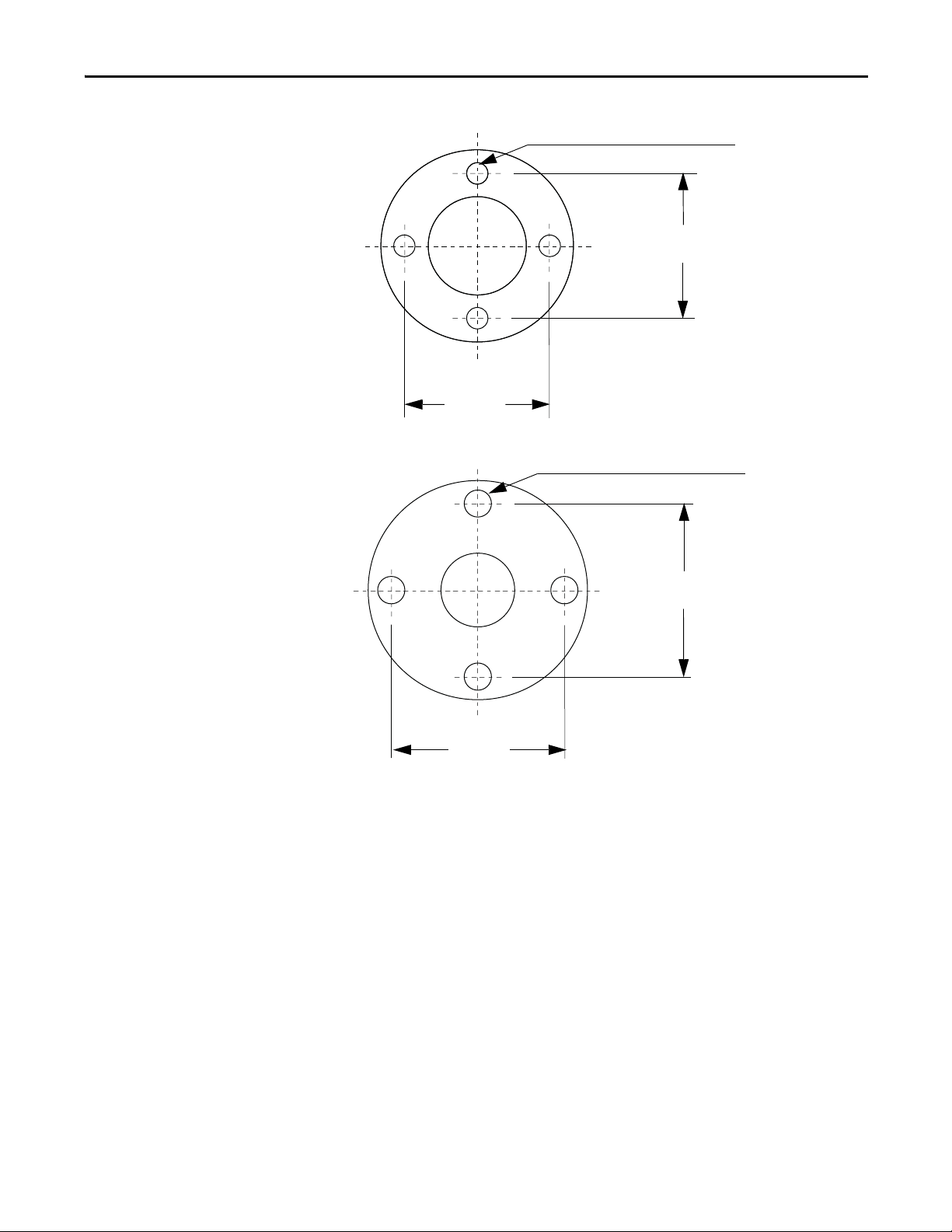
Drive Installation Chapter 2
98.4 (3.9)
98.4
3.9
14.2 (0.560)
• Dimensions in mm (in.)
• Use M12 (0.5 in.) bolt with
washer. Torque to
27...41 N•m (20...30 lb•ft)
• Torque in a cross pattern,
slowly working toward
torque rating
• The flange used must be a
flat type flange. Raised
flanges may break.
• Dimensions in mm (in.)
• Use M16 (5/8 in.) bolt
with washer. Torque to
27...41 N•m (20...30 lb•ft)
• Torque in a cross pattern,
slowly wo rking toward
torque rating
• The flange used must be a
flat type flange. Raised
flanges may break.
18.7 (0.74)
120.6
(4.7)
120.6 (4.7)
Figure 61 - Drive CPVC Class 150 Flange, 1.5 in. (38.1 mm) (ANSI B16.5; ASTM D4024)
Figure 62 - Drive CPVC Class 150 Flange, 2 in. (50.8 mm) (ANSI B16.5; ASTM D4024)
External Piping to the Drive
External Piping Cleaning
Rockwell Automation liquid-cooled drive piping and heat exchangers are flushed
and cleaned at the factory and piping is capped to prevent contamination. Leave
the drive pipe caps installed until final assembly.
Use stainless steel capped piping and valves to maintain cleanliness before
welding or assembly. Parts must be stored in a clean, dry area.
All external piping must be cleaned and flushed before installation to ensure
proper coolant system and drive pump operation.
Rockwell Automation Publication 7000L-UM301D-EN-P - June 2014 77
Page 78

Chapter 2 Drive Installation
Before welding or assembly:
• Remove debris, particulate, oils and greases from inside pipes and valves
before welding.
• Use a high-pressure water spray to remove debris and particulate from
pipes and valve.
• Remove oils and greases with solvents.
Finished pipe system
1. Circulate hot water with industrial detergent through external piping
system only for at least 4...8 hours. Maintain a water temperature of
60…71 °C (140…160 °F). Do not circulate through the drive piping.
2. Circulate clean hot water until the effluent is clear.
Do not allow oils, greases, solvents, cleaning detergents or other cleaning
agents to contact or enter the drive piping as this may cause stress cracking
of CPVC piping.
Refer to ASTM A 380-06 "Standard Practice for Cleaning, Descaling, and
Passivation of Stainless Steel Parts, Equipment, and Systems" for additional
information.
Controlled Siphon into Opentop Reservoir
Rockwell Automation recommends this method of pipe routing for pipes and
heat exchangers higher than the reservoir coolant level. The reservoir is located in
the VFD pump cabinet. This method controls the siphoning of coolant into the
open top reservoir when the coolant pumps are off for maintenance. It prevents
the siphoning of all pipes higher than the reservoir liquid level causing reservoir
overflow. Siphoning occurs only when both pumps are off.
1. Ensure vertical pipe from drive to vent valve is the same size (1-1/2" or
2.0") as the main VFD pipe. The rear outlet flanges may be 1-1/2" or 2.0"
size. Keep the vertical pipe this exact size to maintain minimum coolant
siphon flow into reservoir. Add 1-1/2" Ball Check Valve (Rockwell Part
80025-750-01, Flow Coefficient Cv 80 or equivalent) into vertical exit
piping. Increase pipe size to 2.0" or 3.0" respectively for the remainder of
the pipe circuit.
2. Vents to the top of the reservoir may be 1.0" CPVC pipe or PVC hose. The
end shall not be immersed into the reservoir coolant. Cut a hole into the
top of the reservoir to allow leakage flow.
Vent valve ARV100VS-CP may be obtained from www.plastomatic.com
.
78 Rockwell Automation Publication 7000L-UM301D-EN-P - June 2014
Page 79
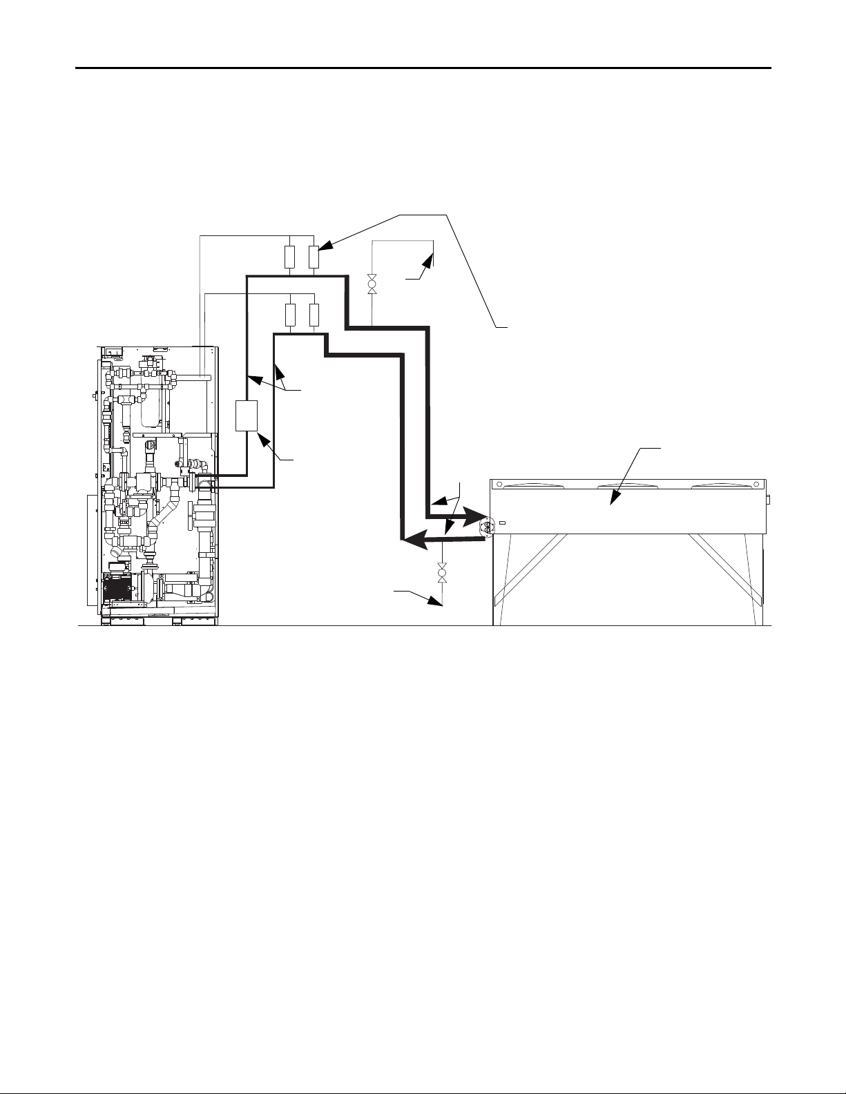
Drive Installation Chapter 2
Drain
Fill
2 or 3 in.
piping
Ball Check
Val ve
1.5 or 2 in.
piping
Ven t Valv e (x4 )
ARV100VS Plastomatic
Mounting Notes:
• 2 ft max section of
horizontal piping for vent
valve mounting
• Horizontal vent valve piping
for exit and return must be
mounted at the same level
Heat Exchanger
3. Fill heat exchanger and pipe using fill line and main VFD piping before
starting pump to purge air. Ensure pumps do not run dry as damage may
occur. Follow priming and valve operation instructions located on pump
cabinet door before operating pumps.
Figure 63 - Controlled Siphon Method
Rockwell Automation Publication 7000L-UM301D-EN-P - June 2014 79
Page 80

Chapter 2 Drive Installation
Drain
Fill
2 or 3 in.
piping
Ball Check
Val ve
1.5 or 2 in.
piping
horizontal piping for vent
valve mounting
for exit and return must be
mounted at the same level
Heat Exchanger
Figure 64 - Controlled Siphon Method with Elevated Heat Exchanger
Liquid-to-Liquid Heat Exchangers
There are three options for routing piping between the liquid-to-liquid heat
exchanger to the supply and return coolant:
• Pipes through top plate of cabinet
• Pipes through bottom plate of cabinet
• Pipes through right side of cabinet
Removable plates are provided in each of these locations.
80 Rockwell Automation Publication 7000L-UM301D-EN-P - June 2014
Page 81

Access for connections
through top of cabinet
Access for connections to
heat exchanger through
right side of cabinet
Liquid-to-Liquid Heat Exchanger
Access for connections to heat
exchanger through bottom of cabinet
Drive Installation Chapter 2
Figure 65 - Connection to Liquid-to-Liquid Heat Exchanger (rear of pumping cabinet shown with
back plates removed)
Rockwell Automation Publication 7000L-UM301D-EN-P - June 2014 81
Page 82

Chapter 2 Drive Installation
Process Water Inlet
Drive Coolant Outlet
1.25 in. or 2.0 in. NPTF
Female Pipe Threads
Process Water Outlet
Drive Coolant Inlet
Figure 66 - Pipe Flange Detail
Table 5 - Customer Cooling Requirements for Liquid-to-Liquid Heat Exchangers
Drive Min. Flow Rate Max. Pressure
Rectifier Voltage Amps US Gpm
(1)
L/m
(2)
(psig)
18 Pulse 4160 375 19.5 72 435 7 > 0 <32
430 21.5 80 435 8 > 0 <32
495 26.5 100 435 13 > 0 <32
575 29.0 109 435 15 > 0 <32
657 37.5 142 435 25 > 0 <32
6600 375 33.0 125 435 18 > 0 <32
430 44.5 167 435 34 > 0 <32
495 48.5 184 435 40 > 0 <32
575 54.5 206 435 43 > 0 <32
657 62.6 237 435 49 > 0 <32
AFE 4160 375 19.5 74 435 7 > 0 <32
430 24.0 90 435 10 > 0 <32
495 26.5 100 435 13 > 0 <32
575 33.0 125 435 19 > 0 <32
6600 375 37.0 139 435 24 > 0 <32
430 44.5 167 435 34 > 0 <32
495 48.5 184 435 40 > 0 <32
575 54.5 206 435 43 > 0 <32
Pressure Drop
(kPa)
Temperature (°C)
Min. Max.
(1) US Gpm = Gallons per minute (U.S.)
(2) L/m = Liters per minute
82 Rockwell Automation Publication 7000L-UM301D-EN-P - June 2014
Page 83

Drive Installation Chapter 2
IMPORTANT
Power and Control Wiring
Drive line-ups (i.e. Drive and Input Starter) which are delivered in two or more
sections, for ease of handling, will require that the power and control wiring be
re-connected. After the sections are brought together, the power and control
wiring is to be reconnected as per the schematic drawings provided.
Control Cables
Control cable entry/exit should be located near the terminal block “TBC” – the
customer’s connections are to be routed along the empty side of the TBC
terminals. These terminals are sized to accept a maximum AWG #14 wire gauge.
The low voltage signals (includes 4-20mA) are to be connected using twisted
shielded cable, with a minimum AWG #18 wire gauge. (Based on using a W4
terminal block for customer connections, comparable wire sizes would be
0.5...4 mm
Of special concern is the encoder signal. Two encoder inputs are provided to
accommodate a quadrature encoder (senses motor direction). The encoder power
supply is isolated and provides +15V and a ground reference. Many encoder
outputs have an open collector output, in which case a pull-up resistor must be
added to ensure that proper signals are fed to the system logic. (Refer to When is
an Encoder Required? on page 414 (Appendix A) to see if one needs to be
supplied.)
2
as equivalent to #22-#10 AWG.)
Low voltage signals are to be connected using twisted shielded cable with the
shield connected at the signal source end only. The shield at the other end is to
be wrapped with electrical tape and isolated. Connections are to be made as
shown on the drawings provided.
Encoder Installation Guidelines
The most frequent problems encountered when transmitting an encoder’s
signal(s) to the drive are signal distortion and electrical noise. Either of these
problems can result in a gain or loss of encoder data counts (quadrature encoders)
or corrupt positional data (absolute encoders). Many of these problems can be
avoided by applying good installation and wiring practices. This section is a
general guideline and recommended practices for field installed equipment. It
applies to either encoder board and both quadrature and absolute encoders.
Protection from Radiated and Conducted Noise
Reasonable care should be taken when connecting and routing power and signal
wiring on a machine or system. Radiated noise from nearby relays, solenoids,
transformers, non linear loads (such as motor drives) etc. can couple onto signal
wires producing undesired pulses. In fact the encoder itself may induce noise into
signal lines run adjacent to it.
Rockwell Automation Publication 7000L-UM301D-EN-P - June 2014 83
Page 84

Chapter 2 Drive Installation
Wrong Shield
Connection
Encoder
Drive
To avoid radiated and/or conducted noise, power and signal lines should be run
separately with a minimum distance between them of at least 75 mm (3 inches).
If they have to overlap somewhere in the system, then the power lines should be
run at 90° to the signal lines. Signal lines should also use twisted pair shielded
cable and run in separate conduit that should be grounded to the building
ground.
Encoder wires and shields should maintain continuity throughout, from the
encoder to the drive. Avoid the use of a terminal block in a junction box. This has
the potential of creating radiated noise and ground loops.
The encoder case must be grounded to the building ground to insure proper and
reliable operation. Most encoders have provision for a case ground connection
through the connector/cable pair if a ground connection cannot be made
through the mounting bracket/machine ground. DO NOT ground the encoder
case through both the machine and cable wiring. Use low capacitance wires
(≤40pf/ft) with 100% shield coverage for long cable runs and connect the shield
only at the drive end.
Figure 67 - Detail Power Terminal Dimensions
For more protection against electrical noise, specify an encoder with
complementary outputs and connect with twisted pair cable. With this type of
cabling, the induced currents will self-cancel.
As a final precaution, ground the shield together with all other parts of the system
that require grounding to a single point ground. This will reduce varying ground
potentials caused by high current fluxes created by motors, remote control
switches and magnetic fields.
Signal Distortion
The primary cause of signal distortion is cable length, more specifically cable
capacitance. Generally speaking the longer the cable length the more there is a
chance of signal distortion at the receiving end. The receiving end responds to
either a logical ‘0’ or a logical ‘1’. Anywhere in between is undefined and the
transition through this region should be < 1.0us. If the leading edge of the
waveform is distorted it causes the transition time through this region to increase.
At some point, the receiver may become unstable and either gain or lose encoder
counts.
84 Rockwell Automation Publication 7000L-UM301D-EN-P - June 2014
Page 85

Drive Installation Chapter 2
To reduce the effects of signal distortion at the encoder receiving electronics, the
following guidelines should be considered:
1. Use a low capacitance cable. Purchase a cable that has a capacitance of
<120pf/m (40pf/ft). As an example Belden 1529A is an 18Awg 3pair
cable having a capacitance of 114pf/m (35pf/ft).
2. Use twisted pair cabling with a shield that covers 100% of the cable. This is
especially true in the case of quadrature encoders. It is still a better choice
for absolute encoders, although the data in these encoders will not exhibit
the same frequency spectrum as quadrature encoders and single wire
cabling can be used. In either case, always check with the encoder
manufacturer for the recommended cable.
3. Keep cable distances as short as is practically possible. Rockwell
Automation’s recommendation for cable distances are:
a. For the 20B-ENC encoders, the distance should be kept to a maximum
of 65m (200 ft). Longer cable distances could cause excessive surge
currents. The operating frequency of the encoder has no bearing on this
recommended distance due to AC Termination used. However, if the
frequency can be kept so that the cable's characteristic impedance is
around 348ohms, this will improve the surge currents and may increase
the maximum distance to 100m (330 ft).
b. For the Universal Encoder Interface, the distance can be extended out
to 200 m (650 ft) @ 100 Khz. This distance can be increased to 500m
at frequencies below 55 Khz. It is not recommended to exceed this
distance since the voltage drop across the cable could cause a lower than
expected power at the encoder.
Unused Inputs
Not all inputs, in either the quadrature or absolute encoders, may be necessary.
For example, the absolute encoder can accept a 12bit encoder but will work with
a lower resolution. Likewise, quadrature encoders may not utilize the Z track.
The following should be used for unused inputs:
1. 20B-ENC Board. Any unused input should be wired to the encoder power
rail. This also includes the B and B’ inputs if using a pulse encoder. Failure
to do this will result in phase loss warnings and improper operation of the
encoder feedback logic (i.e. missing counts).
2. Universal Encode Interface. When used as a quadrature encoder interface,
the same rule applies as for the 20B-ENC Board. When operating as an
absolute encoder interface, the wiring of unused inputs is dependent on
the position of the POL_QRDNT jumper. If the jumper is installed, then
wire all unused inputs to ENC PWR, otherwise use ENC COM.
Rockwell Automation Publication 7000L-UM301D-EN-P - June 2014 85
Page 86

Chapter 2 Drive Installation
4-hole Insulator
Bolts
Lug pad shown with bottom
cable entry orientation
M10 bus
connection
hardware
Customer supplied lugs
4 lugs per phase maximum
Lug pad oriented for
top cable entry
Information Regarding Termination of Customer Cables
Customer termination assemblies can accommodate either top or bottom
customer cable entry.
Figure 68 - Typical Line Cable Termination (shown assembled for bottom cable entry – 18 Pulse)
For top line cable entry, it is necessary to remove the lug pads and re-orient them
as shown in Figure 69
. To remove the lug pads, disconnect the M10 bus
connection hardware (17 mm hex tooling required). Remove the two bolts that
secure the lug pad to the 4-hole insulator. Refer to Torque Requirements for
Threaded Fasteners on page 419 (Appendix B) for Torque Values of electrical
connections.
Figure 69 - Typical Line Cable Terminal Assembly (modified for top cable entry – 18 Pulse)
86 Rockwell Automation Publication 7000L-UM301D-EN-P - June 2014
Page 87

Drive Installation Chapter 2
IMPORTANT
ISOLATION
TRANSFORMER
AC
MOTOR
U (T1)
V (T2)
W (T3)
2U
2V
2W
GROUND BUS
Connected to the neutral point
of the output capacitor
OUTPUT
GROUND
NETWORK
ISOLATION
TRANSFORMER
AC
MOTOR
U (T1)
V (T2)
W (T3)
2U
2V
2W
GROUND BUS
Connected to the neutral point
of the output capacitor
OUTPUT
GROUND
NETWORK
AC
MOTOR
U (T1)
V (T2)
W (T3)
2U
2V
2W
GROUND BUS
AC LI NE
REACTOR
TRANSFORMER
Connected to the neutral point
of the output capacitor
GROUND
FILTER
AC
MOTOR
U (T1)
V (T2)
W (T3)
2U
2V
2W
GROUND BUS
AC LI NE
REACTOR
TRANSFORMER
Connected to the neutral point
of the output capacitor
GROUND
FILTER
Grounding Practices
The purpose of grounding is to:
• provide for the safety of personnel
• limit dangerous voltages on exposed parts with respect to ground
• facilitate proper overcurrent device operation under ground fault
conditions, and
• provide for electrical interference suppression
Generally, the means used for external grounding of equipment should be in
accordance with the Canadian Electrical Code (CEC), C22.1 or the National
Electrical Code (NEC), NFPA 70 and applicable local codes.
Refer to the grounding diagrams that follow for ground connections. The drive’s
main ground bus must be connected to the system ground. This ground bus is the
common ground point for all grounds internal to the drive.
Figure 70 - Ground Connection Diagram with Isolation Transformer
Figure 71 - Ground Connection Diagram with Line Reactor
Each power feeder from the substation transformer to the drive must be provided
with properly sized ground cables. Utilizing the conduit or cable armor as a
ground on its own is not adequate.
Note that if a drive isolation transformer is used, the WYE secondary neutral
point should not be grounded.
Each AC motor frame must be bonded to grounded building steel within 6 m
(20 feet) of its location and tied to the drive’s ground bus via ground wires within
Rockwell Automation Publication 7000L-UM301D-EN-P - June 2014 87
Page 88

Chapter 2 Drive Installation
the power cables and/or conduit. The conduit or cable armor should be bonded
to ground at both ends.
Grounding Guidelines and Practices for Drive Signal and Safety Grounds
When interface cables carrying signals, where the frequency does not exceed
1 MHz, are attached for communications with the drive, the following general
guidelines should be followed:
• It is good practice for the mesh of a screen to be grounded around its whole
circumference, rather than forming a pigtail that is grounded at one point.
• Coaxial cables with a single conductor surrounded by a mesh screen
should have the screen grounded at both ends.
• Where a multi-layer screened cable is used (that is, a cable with both a
mesh screen and a metal sheath or some form of foil), there are two
alternative methods:
– The mesh screen may be grounded at both ends to the metal sheath.
The metal sheath or foil (known as the drain) should, unless otherwise
specified, be grounded at one end only, again, as specified above, at the
receiver end or the end which is physically closest to the main
equipment ground bus.
or
– The metal sheath or foil may be left insulated from ground and the
other conductors and the mesh cable screen grounded at one end only
as stated above.
Grounding Requirements and Grounding Specification for Customers and Power Integrators
An external ground must be attached to the main ground bus. The grounding
means must comply with applicable local codes and standards. As general
guidelines, for information only, the ground path must be of sufficiently low
impedance and capacity that:
• the rise in potential of the drive ground point when subjected to a current
of twice the rating of the supply should be no higher than 4 volts over
ground potential.
• the current flowing into a ground fault will be of sufficient magnitude to
cause the protection to operate.
The main grounding conductor(s) should be run separately from power and
signal wiring so that faults:
• do not damage the grounding circuit
or
• will not cause undue interference with or damage to protection or
metering systems, or cause undue disturbance on power lines.
88 Rockwell Automation Publication 7000L-UM301D-EN-P - June 2014
Page 89

Drive Installation Chapter 2
Identification of Types of Electrical Supplies – Grounded and Ungrounded Systems
When dealing with an ungrounded, three-phase electrical supply system, the
cable insulation must be capable of handling not only the phase-to-phase voltage,
but also the voltage-to-ground if one of the other phases develops a ground fault.
In practice, the cable insulation of an ungrounded, three-phase system must be
good for at least a continuous voltage of root three (1.732) times (1.1) times the
rated voltage of the supply. (1.732 x 1.1 = 1.9 times the rated line-to-line voltage)
Ground Bus
The drive ground bus runs along the top of the drive at the front. The ground bus
is accessible at the top of each of the drive enclosures when the enclosure door is
opened (and the low voltage compartment hinged out in the case of the incomer
cabinet). It is the responsibility of the installer to ensure that the drive is
grounded properly, typically at the point on the ground bus in the incomer
cabinet, close to the incoming power terminations.
Interlocking
Access to the medium voltage areas of the drive is restricted by the use of key
interlocking for safety.
At installation the key interlocking is set up so that access to the medium voltage
compartments of the equipment can only be made when the upstream power is
locked in the off position.
Additionally, the key interlocking prohibits the upstream power being applied
until the medium voltage drive’s access doors have been closed and locked shut.
It is the responsibility of the installer to ensure that the key interlocking is
installed properly to the upstream equipment.
Rockwell Automation Publication 7000L-UM301D-EN-P - June 2014 89
Page 90

Chapter 2 Drive Installation
Notes:
90 Rockwell Automation Publication 7000L-UM301D-EN-P - June 2014
Page 91

Operator Interface
Chapter 3
Chapter Objectives
Terminology
This chapter describes how you use the operator interface to modify and obtain
information contained within the drive. In this chapter you will learn how to:
• Modify information associated with the initial drive setup.
• View:
• drive parameters
• drive status
• View and Reset Alarm Conditions.
• Request printouts of the information in the drive.
• Perform diagnostic trending.
• Modify the operation of the operator interface.
The chapter deals only with the operation of the operator interface. Specific
references to a particular parameter are only for illustrative purposes. Refer to
Publication 7000-TD002_-EN-P
the drive and their use.
Parameter – A memory location within the drive to which data may be written
to or read. Setting a parameter (i.e. writing to it) will modify how the drive
behaves. Prior to using the drive a number of parameters must be set. Additional
parameters may be changed while the drive is in use in order to adjust its
operation, (i.e. the speed could be changed via a parameter).
for information about the actual 'tags' within
Read-only Parameter – A memory location which can only be read. A read-only
parameter contains real-time data and is used to read the current conditions
within the drive, such as running speed.
Ta g – A generic reference to either a parameter or a read-only parameter.
PanelView 550 – The PanelView 550 is a product marketed by Rockwell
Automation consisting of a hardware terminal and a software package, integrated
into a single product. The Medium Voltage Drive only uses the hardware portion
of the product and has replaced the software package.
PowerFlex Operator interface – References to the operator interface refer to the
product consisting of the PanelView 550 interface hardware and the unique
software contained within it, which allows it to function with the Medium
Vol ta ge D ri ve.
Rockwell Automation Publication 7000L-UM301D-EN-P - June 2014 91
Page 92

Chapter 3 Operator Interface
Editing Field – An area of a screen that is displayed in reverse video. When the
field is in this state, data may be entered into it via the keypad.
XIO – the eXternal Inputs and Output adapters used by the drive to interface
hardwired signals to the drive.
Operation – A task which is to be performed. In order to complete the task, a
number of screens may be involved; i.e. selecting a parameter is an operation that
requires at minimum two screens. This operation itself is an operation of
modifying a parameter.
NVRAM – Non-Volatile Random Access Memory. This is memory that is not
affected by loss of power. It is used for long term storage of data such as
parameters and alarm queues.
Flash – A type of memory technology which will indefinitely store information
and is unaffected by power loss. It is used for storage of firmware, parameters and
data files.
PCMCIA – A standard for flash memory cards. Personal Computer Memory
Card International Association.
Overview
The operator interface used on the PowerFlex 7000 Medium Voltage Drive is
that of the PanelView 550 terminal (Figure 72
behave as a PanelView, as only the hardware for the operator interface has been
utilized. The PanelView software has been replaced with unique software to
tailor it to the requirements of the Medium Voltage Drive, and its faceplate has
been modified (Figure 72
Figure 72 - PowerFlex 7000 Drive Operator Interface Terminal
).
). This terminal however does not
92 Rockwell Automation Publication 7000L-UM301D-EN-P - June 2014
Page 93

Operator Interface Chapter 3
Keypad
The keypad of the operator interface consists of two rows of five function keys
(item 1 of Figure 72
Figure 72
will be referred to as the cursor keys (item 2 of Figure 72
are data entry keys consisting of the numeric values 0...9, a decimal point (.), a
negative (-), a backspace key and a data entry key (item 3 of Figure 72
All keys are of a membrane type. The key is executed upon release.
). In the lower right corner of the operator interface are four keys, which
) located below the operator interface display area (item 4 of
). Above the cursor keys
).
Function (Softkeys) Keys
Along the bottom of the display area is one or two rows of 'Softkeys'. These
'Softkeys' represent the physical function keys. The function of the actual keys
will vary between displays. The bottom row of keys (i.e. F6 through F10) is
always shown. The upper row is shown only if they are required for keys (F2
through F5). Thus a single row of 'Softkeys' always refers to the keys F6 through
F10.
Even though the upper row of Softkeys (e.g. F1 through F5) may not be shown
on some displays, the F1-HELP key is always active. (F2 through F5) are only
active if shown.
Cursor (Selection) Keys
The cursor keys are normally used to select an item on the display. When an item
on the display is selected, that item will be displayed in reverse video. To change
the selection, press the key in the desired direction.
On selection screens having more than one page, the page will automatically
change when the cursor is moved beyond the displayed list.
Some displays, such as the Utility screen, use these keys to modify the data value.
Pressing the [cursor up] and [cursor down] keys will change the value by a fine
amount, e.g. one unit. Using the [cursor left] and [cursor right] keys will change
the value by a course amount, e.g. 10 units.
For entries requiring a HEX value, the keys (cursor up/down) are used to scroll to
the desired HEX value.
For parameters which contain an Enumeration string, pressing either the up or
down key will provide a list of options to pick from. Using the cursor keys, make a
selection and press enter. If more options exist than can be displayed on the
screen, a triangle symbol or inverted triangle to the right of the list will show that
there are more selections available in the indicated direction. Continue to use the
up/down cursor keys to move to these additional selections.
Rockwell Automation Publication 7000L-UM301D-EN-P - June 2014 93
Page 94

Chapter 3 Operator Interface
For parameters that are comprised of bit fields, the left/right keys are used to
move to the desired bit field. The up and down keys toggle the bit between its
possible states.
All four cursor keys have an auto feature such that after holding the key for two
seconds, the key will automatically repeat at a rate of five ‘presses’ per second.
Data Entry Keys
As the name implies, these keys are used to enter data. Pressing the keys [0]
through [9] will enter the corresponding value into the 'editing field'. Pressing the
[-] key will change the value to a negative number. Pressing the [.] will allow a
fractional value to be entered.
While entering a value, the value may be edited using the [backspace] key. This
key will remove the right most digit (or decimal point or negative). The help
screen uses the backspace key to return to the previous level of help.
What is a Screen?
The enter key varies depending on the screen. If you are in the process of a
selection operation, the enter key will accept the selection and proceed to a
different screen based on the selection in order to complete the operation. If you
are in the process of entering data, the enter key will accept the edited data.
The operator interface uses menu driven screens to perform various operations on
the drive. You can think of a screen as a window or template, overlaying data from
the drive. The operator interface combines a screen with the drive data, to
formulate what you see on the display area of the operator interface. Individual
screens display a particular type of data and allow selected operations to be
performed on this data. A number of different screens may be used while
performing a single operation.
Components
Although the data displayed on any particular screen will vary, the general
makeup of a screen is the same for all. Figure 73
components.
shows a typical screen and its
94 Rockwell Automation Publication 7000L-UM301D-EN-P - June 2014
Page 95
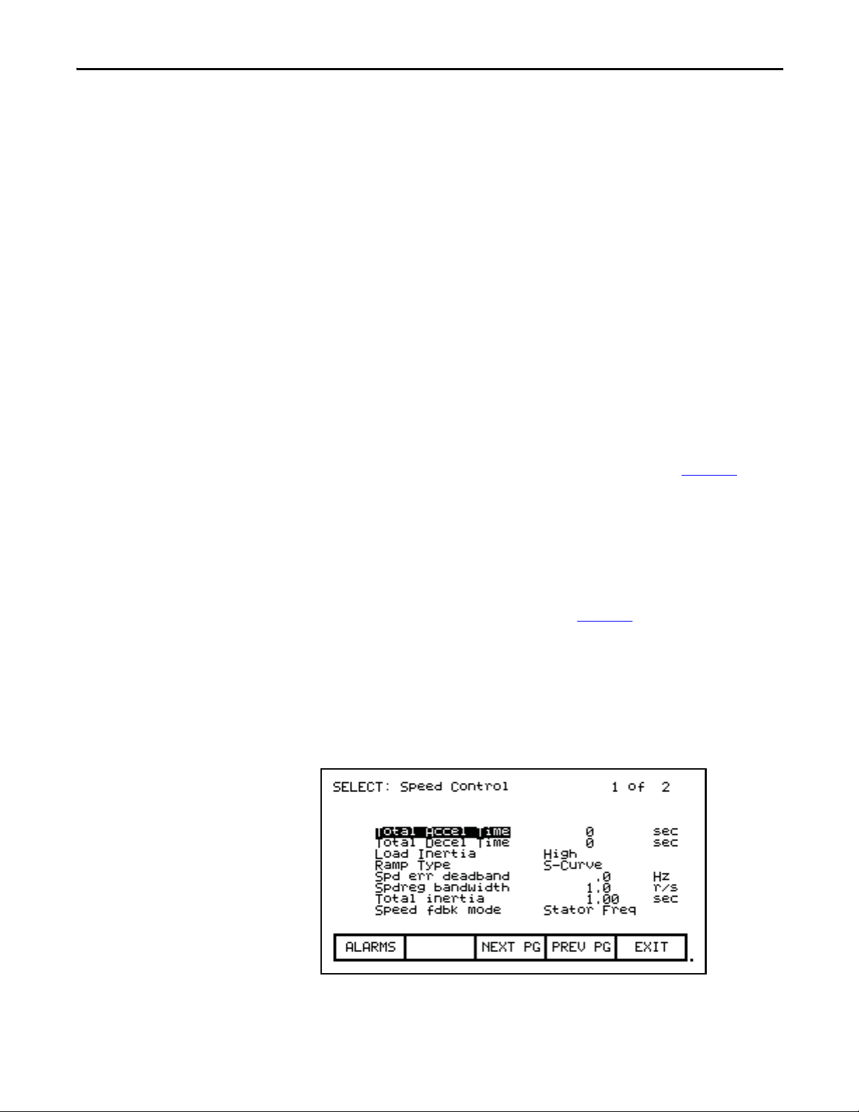
Operator Interface Chapter 3
Figure 73 - Screen Components
The upper left-hand corner contains the name of the screen (i.e. SELECT
GROUP:). Knowing the name of the screen will assist you in the orientation of
the menu system. On some screens to the right of the screen name, will be the
name of the selected item from the previous screen as shown in Figure 74
.
Some screens have more than one page associated with them. The current page
number and the number of pages which make up the data currently being
displayed on the screen is shown in the upper right hand corner (e.g. showing
page 1 of 2 pages).
Along the bottom of the screen are one or two rows of 'Softkeys' which represent
the assignment to the actual function keys. In Figure 73
, Softkeys F6 through F10
are shown. Pressing F8 will display the next page of data.
In the very lower right-hand corner is a small dot. This dot indicates the healthy
state of the operator interface terminal. Under normal conditions this dot will
flash at a rate of .5 Hz. During communication errors, the dot will flash at a rate
of .1 Hz.
Figure 74 - Screen Name & Item
Rockwell Automation Publication 7000L-UM301D-EN-P - June 2014 95
Page 96

Chapter 3 Operator Interface
The remainder of the screen shows the data from the drive. The presentation of
the data is dependent on the screen. Screens that allow an item to be selected
show the current selection in reverse video. An example of this is shown in
Figure 73
in which the Speed Control group is selected.
Information Windows
Numerous screens require communications with the drive in order to function.
At times, the duration of this activity will be noticeable to you. During this
activity, a special 'window' is used within the current screen to inform you of this
activity. The time required for the activity will vary.
Accessing/Writing to Drive
When first powered up, the operator interface knows very little about the
information in the drive. As each screen is activated, the operator interface
requests information from the drive, which it will store within the operator
interface for future reference. When the operator interface requests information
from the drive, a window is used to display a message "Accessing Drive ...". During
this time, the operator interface will not respond to any user input, until the task
at hand is completed. You will notice that subsequent activation of the same
screen for the same data will be much quicker since the operator interface already
has most or all of its required information.
You can selectively choose to download the complete database to the operator
interface on command, thus eliminating the initial access
the operator interface will automatically download the database on power-up, or
during periods of inactivity. Refer to Database Download
Some screens require that information be written to the drive. During this task, a
window is used to display the message "Writing to Drive...” During this time, the
operator interface will not respond to any user input, until the task at hand is
completed.
delays. If uninterrupted,
on page 162.
Communication Error
While the operator interface is reading or writing to the drive, it is possible for
communications to be disrupted for a number of reasons. If this were to occur, a
special window is used to inform you of this. During this time, the operator
interface will not respond to any user input, until the task at hand is completed.
96 Rockwell Automation Publication 7000L-UM301D-EN-P - June 2014
Page 97
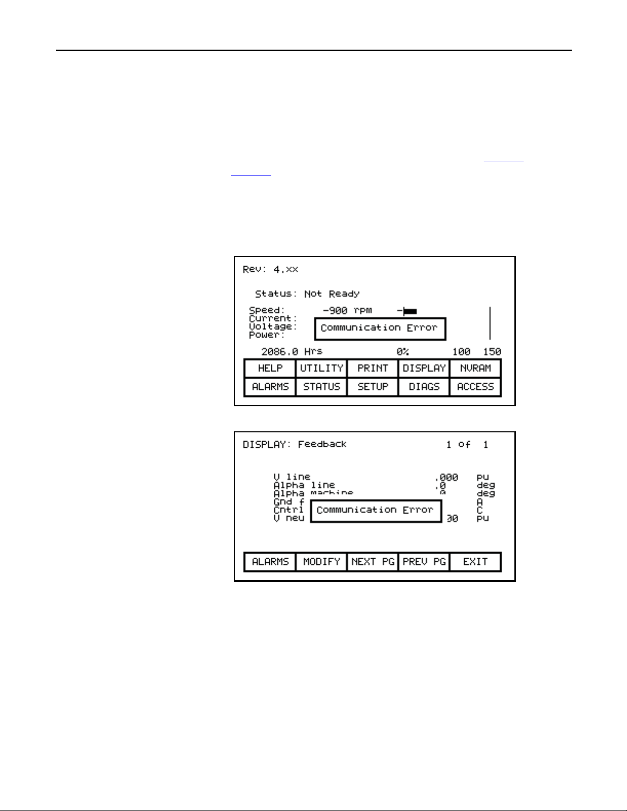
Operator Interface Chapter 3
The window for the "Communication Error" can take on two forms. If a window
has already been displayed showing "Accessing Drive" or Writing to Drive", then
the communication error message will be added to the window already in use.
Some screens constantly read from the drive in order to show real-time data. An
example of this is the 'Top Level Menu’. When a communication error occurs on a
screen showing real-time data, a window is opened showing a box around the
"Communication Error". Two examples of this are shown in Figure 75
Figure 76
.
and
In both cases, once communications has been re-established, the information
window will be removed and the operator interface will return to normal
operation.
Figure 75 - Communications Error
Figure 76 - Communications Error
Languange Changing
When the language used by the drive changes, (either via the operator interface or
an external device), the operator interface must do considerable work. The
database strings are all invalidated, the character set for the server is changed and
all strings used by the operator interface are linked to the new language. During
this possibly lengthy process, the “Language Changing ...” message is displayed.
Rockwell Automation Publication 7000L-UM301D-EN-P - June 2014 97
Page 98

Chapter 3 Operator Interface
General Operation
The operations that can be performed on a screen vary depending on the actual
screen being displayed. The majority of the operations are activated by the
function keys located along the bottom of the screen. Although the meaning of
these keys does change from one screen to the next, there are some functions
which are available on most screens and always have the same assignment.
The operations for these latter keys will not be explained within the description
of individual screen operations. They are explained here and apply equally to all
screens.
F1 - Help
This operation is active on every screen, even if the 'Softkey' is not displayed.
Help is context sensitive and will display help that relates to the screen that you
are currently viewing.
F6 - Alarms
The F6 'Softkey' will always get you to the Alarm Summary Screen. A new alarm
will cause this key to flash in reverse video.
F8 - Next Page
When a screen is capable of displaying data that requires more than one page, this
'Softkey' will be active. The 'Softkey' will increment the page number being
viewed.
F9 - Previous Page
When a screen is capable of displaying data that requires more then one page, this
'Softkey' will be active. The 'Softkey' will decrement the page number being
viewed.
F10 - Exit
When you are viewing any screen other than the Top Level Menu, this 'Softkey'
will return you to the previous screen.
98 Rockwell Automation Publication 7000L-UM301D-EN-P - June 2014
Page 99

Operator Interface Chapter 3
Operator Interface Power-up Sequence
When the operator interface is powered up or reset, it will go through two
noticeable operations:
1. Linking to Drive - During this phase the operator interface is establishing
communications with the drive communications board. The screen will
also show information about the software product contained in the
PowerFlex operator interface, such as:
a. software part number and revision level
b. date and time stamp of program creation
2. Obtaining Drive Database - During this phase, the database of
information about the drive is obtained from the drive. Obtaining the
database at this point in time is optional and may be aborted by pressing
any key on the operator interface. Obtaining the entire database does
however speed up subsequent operations since relevant portions of the
database do not have to be obtained. (Without obtaining the entire
database, the operator interface will access portions of the drive database as
required. This slows down the first access to the operation that requires the
data. Subsequent operations requiring the same data are not affected).
Aborting the download will not affect portions of the database already
obtained.
Once the database has been obtained, the operator interface will start up in one
of two modes, depending on to what degree the drive has previously been
configured:
Top Level Menu
1. On an unconfigured drive, the operator interface will enter the 'Setup
Wizard' mode. Until the user has gone through the entire 'Setup Wizard',
this will be the default mode to power up in. The 'Setup Wizard' can be
cancelled at any time by pressing the appropriate softkey.
2. Once the drive has been configured through the 'Setup Wizard', the Top
Level Menu, will be displayed from this point forward. The 'Setup Wizard'
can be re-entered via the Setup Menu.
This screen (Figure 77) represents the main menu from which all other screens
(and the operations which they perform) are activated. To activate an operation,
simply press the function key corresponding to the 'Softkey' shown on the screen.
A screen for that operation will be displayed. Refer to the section entitled "How
To:" for information about the various operations which may be performed.
The screen identifies the drive product to which the operator interface is attached
and its overall state of operation. Four digital meters show four selected
parameters located in the drive. A Hobbs meter displays the number of hours that
the drive has been running.
Rockwell Automation Publication 7000L-UM301D-EN-P - June 2014 99
Page 100

Chapter 3 Operator Interface
The status of the drive will show one of the following:
NOT READY – drive is not ready to start
READY – drive will start when commanded
FORWARD RN – drive is running in the forward direction
REVERSE RN – drive is running in the reverse direction
WA RN IN G – d ri ve ha s a wa rn in g
FAULTED – the drive is faulted
DISCHARGING – waiting for the input filter capacitor to discharge on an
Active Front End drive before re-start
Figure 77 - Top Level Menu
How To
The following sections describe how to perform the various operations on the drive,
using the operator interface. Throughout the discussion, a number of screens will
be used to achieve the desired operation. In many cases, the same screen will be used
for more than one operation, however with possibly different data from the drive.
Throughout the section, you want to focus on how the operation is performed.
The operator interface will take care of what screens are needed to perform the
operation.
Obtain Help
Help is obtained for any screen by pressing the [F1] function key. Figure 78
shows the help screen, which is displayed for the Top Level Menu. After the name
of the screen (i.e. HELP:) is the name of the screen for which help is being
accessed. (In this case the name of the Top Level Menu is REV.) This particular
help screen contains three pages. To view page two, press the [F8] key. Page 2 is
displayed. To return to page 1, press the [F9] key.
100 Rockwell Automation Publication 7000L-UM301D-EN-P - June 2014
 Loading...