

Page 1

Bulletin 7000 User Manual
PowerFlex® 7000 Medium Voltage AC Drive Air-Cooled
(“A” Frame)—ForGe Control
(Using PanelView 550)
Publication 7000A-UM151D-EN-P
Page 2
Important User Information
IMPORTANT
Solid-state equipment has operational characteristics differing from those of electromechanical equipment. Safety
Guidelines for the Application, Installation and Maintenance of Solid State Controls (publication SGI-1.1
your local Rockwell Automation sales office or online at http://www.rockwellautomation.com/literature/
important differences between solid-state equipment and hard-wired electromechanical devices. Because of this difference,
and also because of the wide variety of uses for solid-state equipment, all persons responsible for applying this equipment
must satisfy themselves that each intended application of this equipment is acceptable.
In no event will Rockwell Automation, Inc. be responsible or liable for indirect or consequential damages resulting from the
use or application of this equipment.
The examples and diagrams in this manual are included solely for illustrative purposes. Because of the many variables and
requirements associated with any particular installation, Rockwell Automation, Inc. cannot assume responsibility or
liability for actual use based on the examples and diagrams.
No patent liability is assumed by Rockwell Automation, Inc. with respect to use of information, circuits, equipment, or
software described in this manual.
Reproduction of the contents of this manual, in whole or in part, without written permission of Rockwell Automation,
Inc., is prohibited.
Throughout this manual, when necessary, we use notes to make you aware of safety considerations.
available from
) describes some
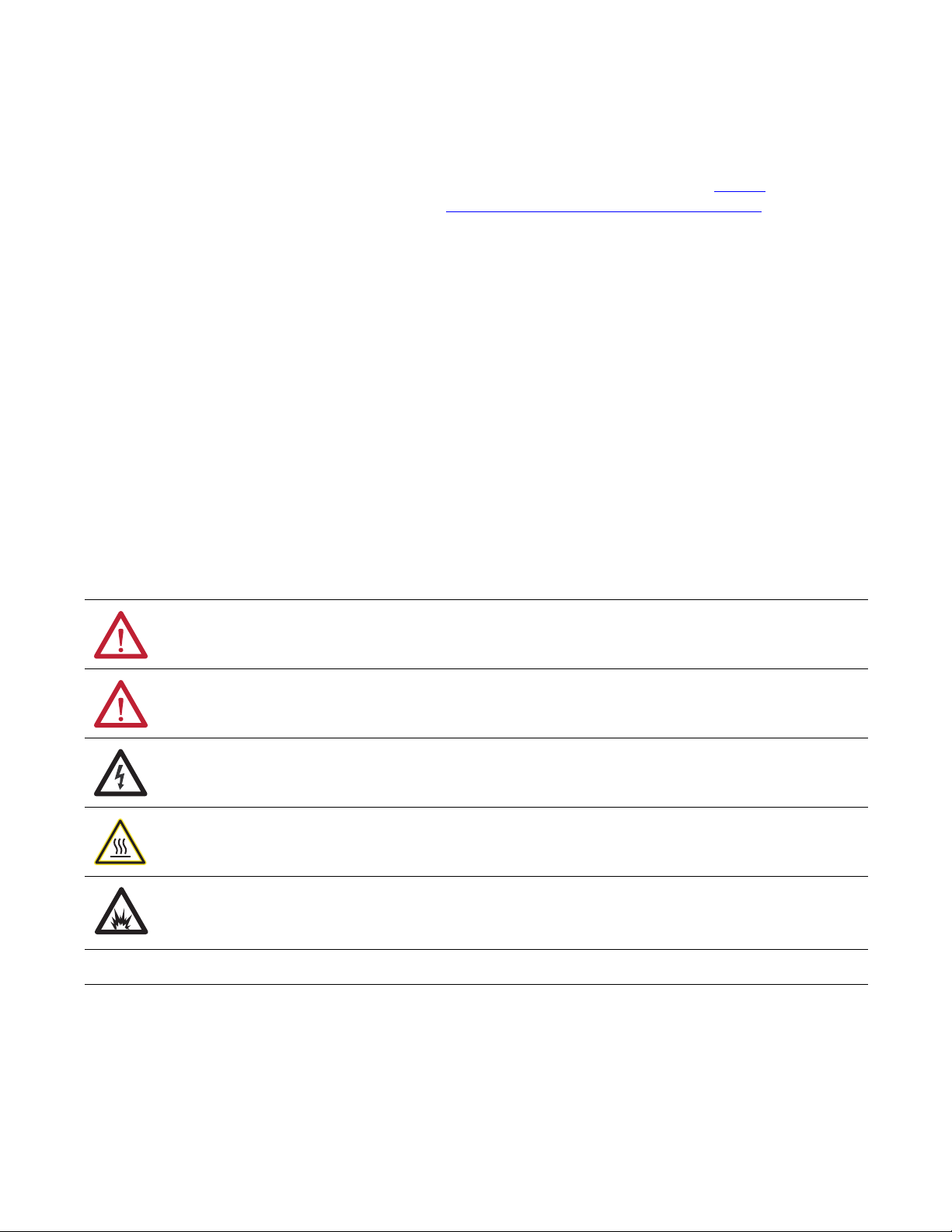
WARNING: Identifies information about practices or circumstances that can cause an explosion in a hazardous environment,
which may lead to personal injury or death, property damage, or economic loss.
ATTENTION: Identifies information about practices or circumstances that can lead to personal injury or death, property
damage, or economic loss. Attentions help you identify a hazard, avoid a hazard, and recognize the consequence.
SHOCK HAZARD: Labels may be on or inside the equipment, for example, a drive or motor, to alert people that dangerous
voltage may be present.
BURN HAZARD: Labels may be on or inside the equipment, for example, a drive or motor, to alert people that surfaces may
reach dangerous temperatures.
ARC FLASH HAZARD: Labels may be on or inside the equipment, for example, a motor control center, to alert people to
potential Arc Flash. Arc Flash will cause severe injury or death. Wear proper Personal Protective Equipment (PPE). Follow ALL
Regulatory requirements for safe work practices and for Personal Protective Equipment (PPE).
Identifies information that is critical for successful application and understanding of the product.
Allen-Bradley, Rockwell Software, Rockwell Automation, and TechConnect are trademarks of Rockwell Automation, Inc.
Trademarks not belonging to Rockwell Automation are property of their respective companies.
Page 3

Table of Contents
Preface Overview Who should use this Manual .................................................... P-1
What is not in this Manual ....................................................... P-1
Manual Conventions ................................................................ P-2
General Precautions ................................................................. P-3
Who to call for Commissioning ............................................... P-3
Chapter 1 Overview of Drive Introduction .............................................................................. 1-1
Drive Configurations ............................................................... 1-2
Topology .................................................................................. 1-3
Rectifier Designs
Active Front End (AFE) Rectifier .................................... 1-4
“Direct-to-Drive” Technology ................................................ 1-5
Motor Compatibility ................................................................ 1-6
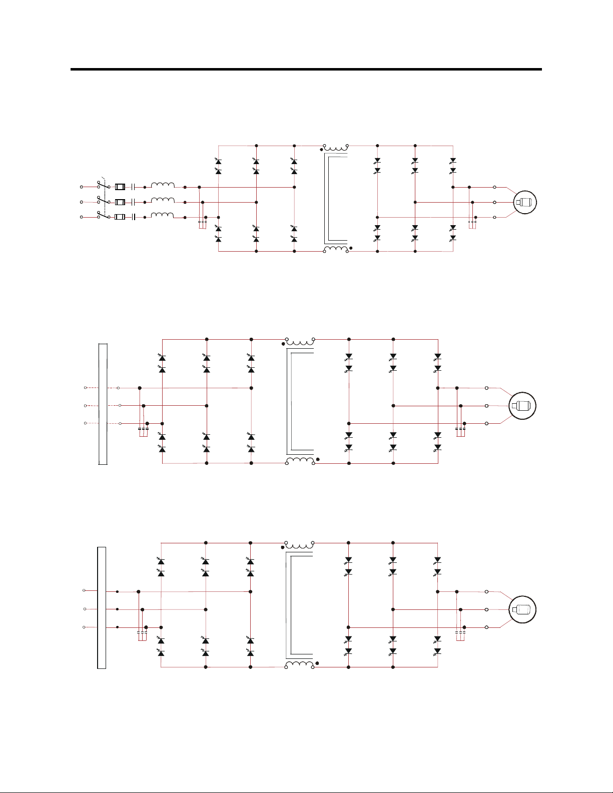
Simplified Electrical Drawings
2400 volt – Active Front End (AFE) Rectifier .................. 1-7
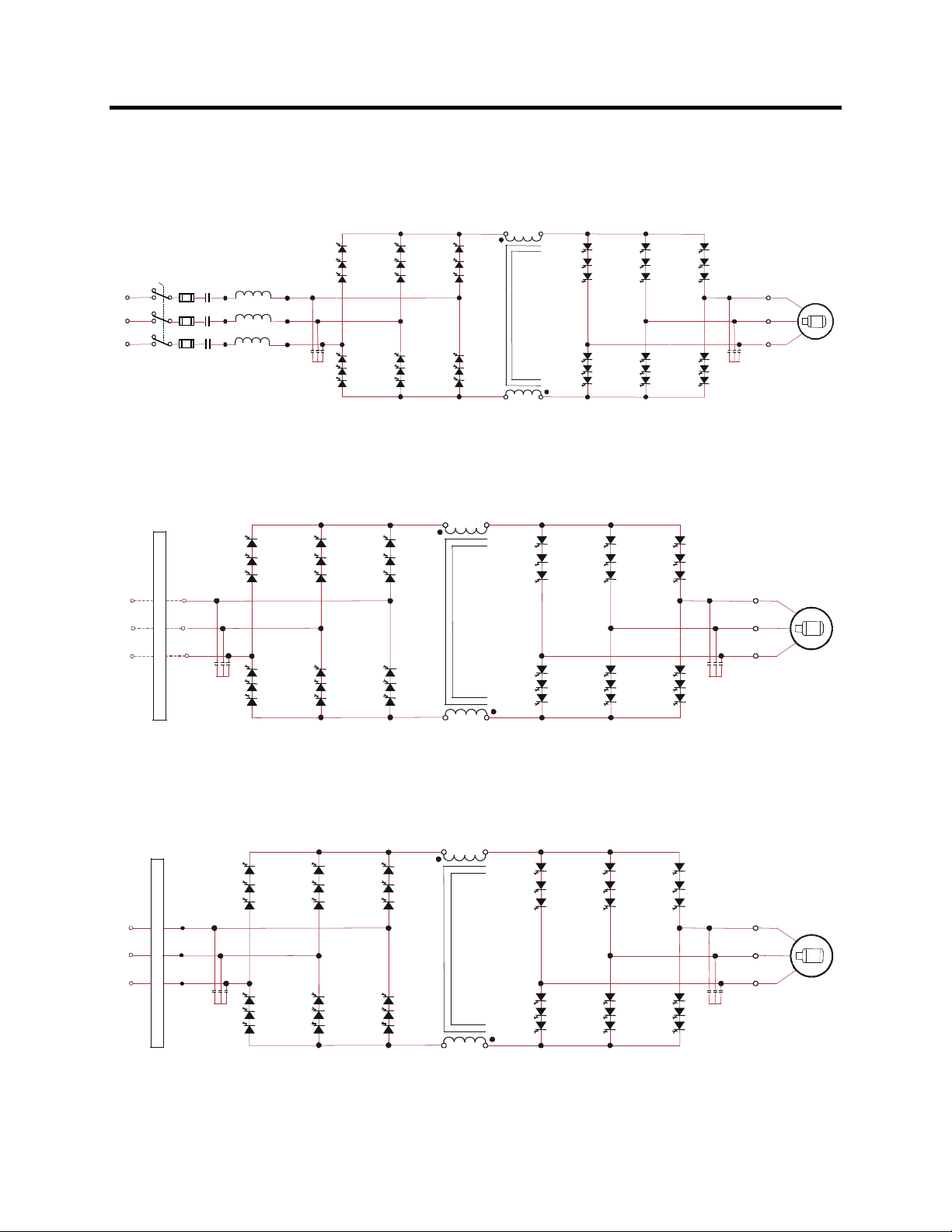
3300/4160 volt – Active Front End (AFE) Rectifier ......... 1-8
6600 volt – Active Front End (AFE) Rectifier .................. 1-9
Operator Interface .................................................................. 1-10
Chapter 2 Drive Installation Safety and Codes ..................................................................... 2-1
General Handling Procedures .................................................. 2-1
Drive Storage ........................................................................... 2-1
Siting of the Drive ................................................................... 2-2
Site Considerations ............................................................ 2-2
Installation ............................................................................... 2-4
Installation of Exhaust Air Hood ...................................... 2-4
Installation of Integral Transformer Cooling Fan ............. 2-8
Neutral Resistor Assembly ............................................... 2-9
Installation of Neutral Resistor Assembly ...................... 2-10
Cabinet Layout and Dimensional Drawings of Drive ............ 2-11
PowerFlex 7000 “A” Frame Dimensional Drawing .............. 2-12
Drive Layout .......................................................................... 2-13
Direct-to-Drive AFE Rectifier Configuration #1 ............ 2-13
AFE Rectifier (Separate Isol. Transformer (Config. #2) ..... 2-14
AFE Rectifier (Integral Isol. Transformer (Config. #3) ....... 2-15
Cabling Cabinet #1 (with Input Starters) .............................. 2-16
Cabling Cabinet #1 (without Input Starters) ......................... 2-17
Cabling Cabinet #2 ............................................................... 2-18
Cabling Cabinet #3 ............................................................... 2-19
Converter Cabinet .................................................................. 2-20
Control/DC Link/Fan Cabinet ............................................... 2-21
Low Voltage Control Tub ...................................................... 2-22
IEC Component and Device Designations ............................ 2-24
Power Wiring Selection ......................................................... 2-24
Cable Insulation .............................................................. 2-25
Wire Group Numbers ...................................................... 2-26
7000 “A” Frame 7000A-UM151D-EN-P – March 2013
Page 4

ii Table of Contents
Chapter 2 Drive Installation
Power Cabling Access ........................................................... 2-27
(cont.)
To access the customer power cable terminations .......... 2-27
Power Connections ................................................................ 2-28
Line/Motor Terminations ................................................ 2-28
Power Cabling Installation Requirements ....................... 2-28
Dimension Views:
Cabling Cabinet for Config. #1 with Input Starter ......... 2-29
Cabling Cabinet for Config. #1 without Input Starter ..... 2-30
Cabling Cabinet for Config. #2 ...................................... 2-31
Cabling Cabinet for Config. #3 ...................................... 2-32
Power and Control Wiring ..................................................... 2-33
Control Cables ................................................................ 2-33
Grounding Practices ............................................................... 2-34
Grounding Guidelines and Practices for Drive Signal
and Safety Grounds ................................................... 2-35
Grounding Requirements and Specifications for
Customer and Power Integrators .............................. 2-36
Identification of Types of Electrical Supplies
– Grounded and Ungrounded Systems ..................... 2-36
Ground Bus ..................................................................... 2-36
Interlocking ............................................................................ 2-37
Chapter 3 Operator Interface Chapter Objectives ................................................................... 3-1
Terminology ............................................................................ 3-1
Overview ................................................................................. 3-3
Keypad .............................................................................. 3-3
Function (Softkeys) Keys ........................................... 3-3
Cursor (Selection) Keys .............................................. 3-4
Data Entry Keys .......................................................... 3-4
What is a Screen? .............................................................. 3-5
Components ................................................................ 3-5
Information Windows ................................................. 3-6
Accessing/Writing to Drive .................................. 3-7
Communication Error ........................................... 3-7
Language Changing ............................................. 3-8
General Operation ....................................................... 3-8
Operator Interface Power-up Sequence ............................. 3-9
Top Level Menu .............................................................. 3-11
How to:
Obtain Help ..................................................................... 3-12
Related Topics .......................................................... 3-12
Help On Help ............................................................ 3-13
Modify Operator Interface Operation (Utility) ............... 3-14
Changing Backlight Delay ........................................ 3-14
Changing Contrast .................................................... 3-15
7000A-UM151D-EN-P – March 2013 7000 “A” Frame
Page 5

Table of Contents iii
Chapter 3 Operator Interface
Setting Time ............................................................. 3-16
(cont.)
Setting Date .............................................................. 3-17
Selecting Meters ....................................................... 3-17
Viewing Revision Levels .......................................... 3-20
Transfer Data in Memory ......................................... 3-21
Picking an Access Level ........................................... 3-21
Select a Parameter ............................................................ 3-22
Via Groups ................................................................ 3-22
Via Name .................................................................. 3-23
Via Code ................................................................... 3-24
Edit Text .......................................................................... 3-26
Configure the Drive ......................................................... 3-28
Enter/Modify an Access Level ................................. 3-28
Drive Set-up .............................................................. 3-32
Language Selection ............................................ 3-33
Modify Parameters ............................................. 3-34
Numerical Value ................................................ 3-34
Enumerated Value .............................................. 3-36
Bit Encoded Value ............................................. 3-37
Analog Ports ....................................................... 3-38
Fault Masks ........................................................ 3-39
User Definable External Text ............................. 3-42
PLC .................................................................... 3-43
XIO ..................................................................... 3-45
Message Prompting .................................................. 3-45
Store/Retrieve Configuration (NVRAM) ................. 3-46
Initialize ............................................................. 3-46
Save .................................................................... 3-47
Load ................................................................... 3-47
Display Parameters .......................................................... 3-48
Custom Group ........................................................... 3-50
View Drive Status ........................................................... 3-51
View and Reset Alarms ................................................... 3-51
Help for Alarms ........................................................ 3-52
Request Printouts ............................................................ 3-53
Loading Programs (Firmware) ........................................ 3-54
Parameter Transfers ........................................................ 3-56
Upload to Operator Interface ............................. 3-57
Download from Operator Interface .................... 3-57
Upload to Memory Card .................................... 3-57
Download from Memory Card ........................... 3-58
Parameter File Format ........................................ 3-58
Loading Language Modules ............................................ 3-59
System Programming ...................................................... 3-60
7000 “A” Frame 7000A-UM151D-EN-P – March 2013
Page 6

iv Table of Contents
Operator Interface Menu Hierarchy Chart
Chapter 3 Operator Interface
What does it show? ......................................................... 3-61
(cont.)
How do you read it? ........................................................ 3-61
Example ........................................................................... 3-62
PowerFlex 7000 “A” Frame Terminal Menu Tree .......... 3-63
PCMCIA Memory Card Installation Data
Description ...................................................................... 3-65
Installing the Memory Card ............................................ 3-65
Cabling Cabinet for Config. #1 (Direct-to-Drive) ................. 4-1
Chapter 4 Component Definition
Cabling Cabinet for Config. #1
and Maintenance
(Direct-to-Drive, optional Input Starter) .......................... 4-2
Cabling Cabinet for Config. #2
(AFE Rectifier with Separate Isolation Transformer) ....... 4-3
Cabling Cabinet for Config. #3
(AFE Rectifier with Integral Isolation Transformer) ....... 4-4
Converter Cabinet Components ............................................... 4-5
Converter Cabinet .................................................................... 4-6
Surge Arresters ....................................................................... 4-6
Description ....................................................................... 4-6
Operation .......................................................................... 4-7
Field Test and Care .......................................................... 4-7
PowerCage™ ........................................................................... 4-8
SGCT and Snubber Circuit .................................................... 4-11
Uniform Clamping Pressure .................................................. 4-12
Checking Clamping Pressure ................................................. 4-13
Clamping Pressure Adjustment ....................................... 4-13
Temperature Sensing ............................................................. 4-14
Symmetrical Gate Commutated Thyristor Replacement ....... 4-15
Snubber Resistors .................................................................. 4-18
Testing Snubber Resistors ............................................... 4-18
Fiber Optic Cabling .............................................................. 4-19
Air Pressure Sensor ................................................................ 4-19
DC Link/Fan/Control Components ........................................ 4-20
Filter Capacitors .............................................................. 4-21
Filter Capacitor Replacement .......................................... 4-22
Testing Filter Capacitors ................................................ 4-23
First Method ............................................................ 4-23
Second Method ........................................................ 4-24
Recommended Digital Multimeters (DMM) .................. 4-27
Fan Replacement ................................................................... 4-28
DC Link Section .............................................................. 4-28
Safety Notes .................................................................... 4-28
Fan Installation ................................................................ 4-29
Top of Integral Isolation Transformer Section ................ 4-29
Top of Integral Line Reactor/Input Starter Section ......... 4-29
7000A-UM151D-EN-P – March 2013 7000 “A” Frame
Page 7

Table of Contents v
Impeller Maintenance (DC Link/Fan Section) ...................... 4-31
Chapter 4 Component Definition
Impeller Removal from Motor Shaft ............................... 4-31
and Maintenance
Safety Notes .................................................................... 4-31
(cont.)
Installation of Impeller Assembly onto Motor Shaft ....... 4-32
Impeller Maintenance ........................................................... 4-34
Isolation Transformer Cooling Fan ................................. 4-34
Inlet Ring Removal and Replacement ................................... 4-34
Safety Notes .................................................................... 4-34
DC Link / Fan Section ..................................................... 4-34
Procedure ......................................................................... 4-34
Top on Integral Isolation Transformer Section ............... 4-35
Replacement of Air Filters ..................................................... 4-35
Procedure ......................................................................... 4-35
Control Power Components ................................................... 4-38
Ride-Through .................................................................. 4-38
AC/DC Power Supply ............................................................ 4-41
Description ...................................................................... 4-41
Location ........................................................................... 4-42
Low Voltage Control Section ................................................ 4-44
DC/DC Power Supply ............................................................ 4-46
Description ...................................................................... 4-46
IO Connectors on Control Boards ........................................ 4-47
Drive Processor Module ........................................................ 4-48
ACB Analog Control Board .................................................. 4-49
Interface Module (IFM) ................................................. 4-50
Analog Inputs and Outputs .............................................. 4-50
External Input/Output Boards ................................................ 4-51
Optical Interface Boards ........................................................ 4-53
Environmental Considerations ............................................... 4-55
Hazardous Materials ........................................................ 4-55
Disposal ........................................................................... 4-57
Appendix A Commissioning Start-up Commissioning Services ........................................... A-1
Drive Commissioning ...................................................... A-1
Appendix B Catalog Number Catalog Number Explanation................................................... B-1
Control Power Transformer Selection ............................... B-2
PowerFlex 7000 Drive Selection Explanation ........................ B-3
When is a Tachometer Required? ........................................... B-4
PowerFlex 7000 Drive Performance ....................................... B-5
Glossary of Terms ................................................................... B-5
Typical Application Load Torque Profiles ............................. B-6
Explanation Supply Voltage, Control Voltage, Frequency and
7000 “A” Frame 7000A-UM151D-EN-P – March 2013
Page 8

vi Table of Contents
Appendix C Torque Requirements Torque Requirements for Threaded Fasteners ........................ C-1
Appendix D Meggering Drive Meggering ..................................................................... D-1
Meggering the PowerFlex 7000A ........................................... D-1
Equipment Required ......................................................... D-2
Procedure .......................................................................... D-2
Preventive Maintenance Check List ....................................... E-1
Appendix E Preventative
Operational Maintenance ........................................................ E-1
Maintenance
Annual Maintenance ............................................................... E-2
Initial Information Gathering ........................................... E-2
Physical Checks (NO Medium Voltage and
NO Control Power) .................................................... E-2
Control Power Checks (NO Medium Voltage) ................ E-4
Final Power Checks before Restarting ............................. E-4
Additional Tasks During Preventive Maintenance .......... E-5
Final Reporting ................................................................. E-5
Time Estimations ............................................................. E-6
Tool / Parts / Information Requirements .......................... E-7
Maintenance Schedule ........................................................... E-8
Preventative Maintenance Service Schedule ......................... E-9
General Notes ...................................................................... E-11
Maintenance of MV Motor Control Equipment ............ E-11
Periodic Inspection ........................................................ E-11
Contamination ............................................................... E-12
High Voltage Testing .................................................... E-12
Maintenance after a Fault Condition ............................. E-12
Part-specific Notes ............................................................... E-13
Cooling Fans ................................................................. E-13
Operating Mechanisms .................................................. E-13
Contacts ......................................................................... E-13
Vacuum Contactors ....................................................... E-13
Power Cable and Control Wire Terminals ................... E-14
Coils ............................................................................. E-14
Batteries ......................................................................... E-14
Pilot Lights .................................................................... E-14
Solid-State Devices ....................................................... E-15
Locking and Interlocking Devices ................................ E-15
Appendix F Specifications Specifications ........................................................................... F-1
Dimensions/Weights ............................................................... F-4
Nominal Power Ratings .......................................................... F-4
7000A-UM151D-EN-P – March 2013 7000 “A” Frame
Page 9

Preface
Overview
Who Should Use This Manual This User Manual is intended for use by personnel familiar with
medium voltage and variable speed solid-state drive equipment. The
manual contains material that will allow the user to operate the drive
system.
What Is Not in this Manual This manual is designed to provide only information specific to the
PowerFlex 7000 “A” Frame drive. Therefore customer specific
topics are not presented. These customer specific topics include:
• Dimensional and Electrical Drawings generated for each
customer specific order. (This manual does provide generic
drawings for illustrative purposes only.)
• Spare Parts Lists compiled for each customer specific order.
(This manual does provide a generic list of possible components
and a description of their characteristics and functionality.)
The above information is provided to the customer during the
Three User Manuals address this product line:
If you have multiple drive types or power ranges, ensure you have
For detailed information on Troubleshooting, Parameters and
For detailed information on receiving and handling for Medium
Reference Manuals (for “A”, “B” and “C” Frame drives) are also
Please note: This manual deals specifically with the PowerFlex 7000
order process cycle.
“A” Frame for lower power air-cooled configurations
(up to approximately 1250 hp/933 kW)
“B” Frame for higher power air-cooled configurations
“C” Frame for all liquid-cooled configurations
the correct manual.
Functional Description for MV variable frequency drives, please
refer to Technical Data publication 7000-TD002_-EN-P.
Voltage variable frequency drive and related equipment, please refer
to General Handling Procedures, publication 7000-IN002_-EN-P.
available. These manuals provide additional technical information
about the drive components. Contact your local Rockwell
Automation Sales office to order copies of these publications.
“A” Frame drive. Information on auxiliary cabinetry or special
components we are contracted to supply with the drive will be
contained within the Service Manual you will receive with your order.
7000 “A” Frame 7000A-UM151D-EN-P – March 2013
Page 10
P-2 Preface
Manual Conventions Symbols are used throughout this manual to indicate specific types
of information.
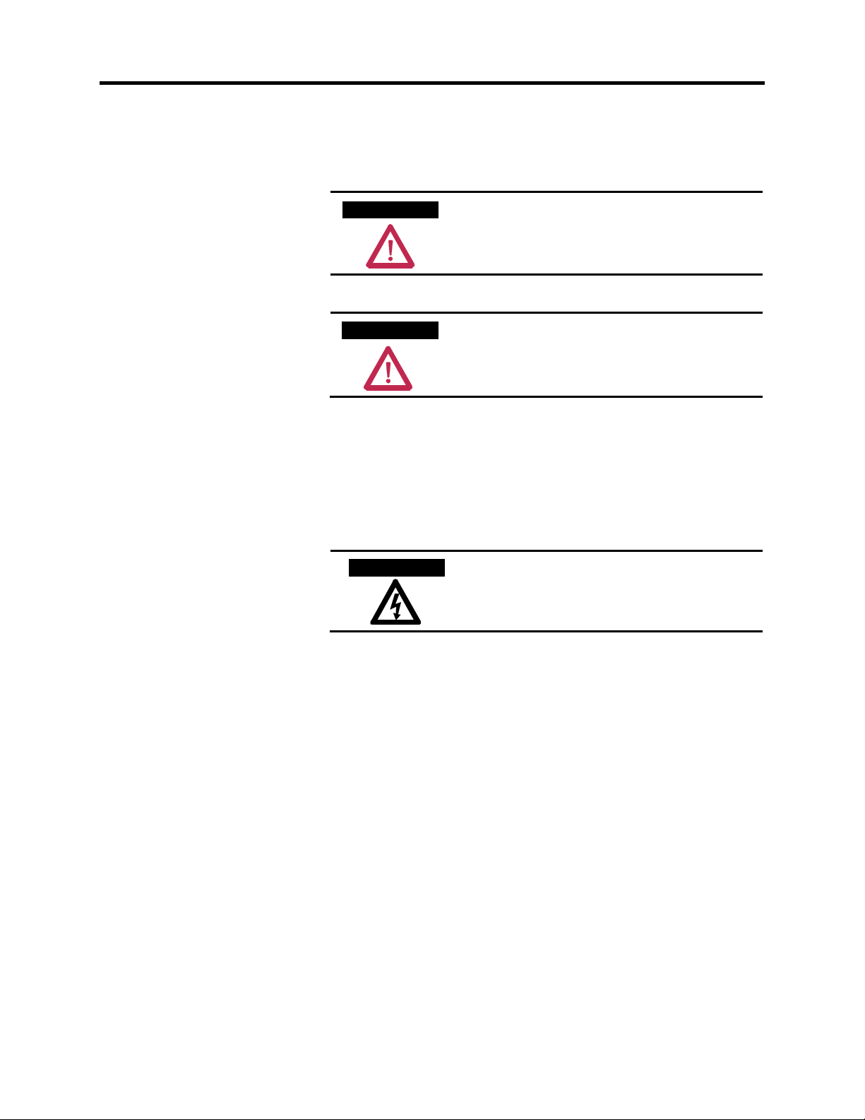
W A R N I N GW A R N I N G
Warnings tell readers where people may be
hurt if procedures are not followed properly.
A T T E N T I O NA T T E N T I O N
Cautions tell readers where machinery may be
damaged or economic loss can occur if
procedures are not followed properly.
Both of the above could indicate:
• A possible trouble spot
• Tell what causes the trouble spot
• Give the result of an improper action
• Tell the reader how to avoid trouble
S H O C K H A Z A R DS H O C K H A Z A R D
This symbol alerts the user to a potential
electrical shock hazard that exists on a
component or printed circuit board.
7000A-UM151D-EN-P – March 2013 7000 “A” Frame
Page 11
Preface P-3
General Precautions
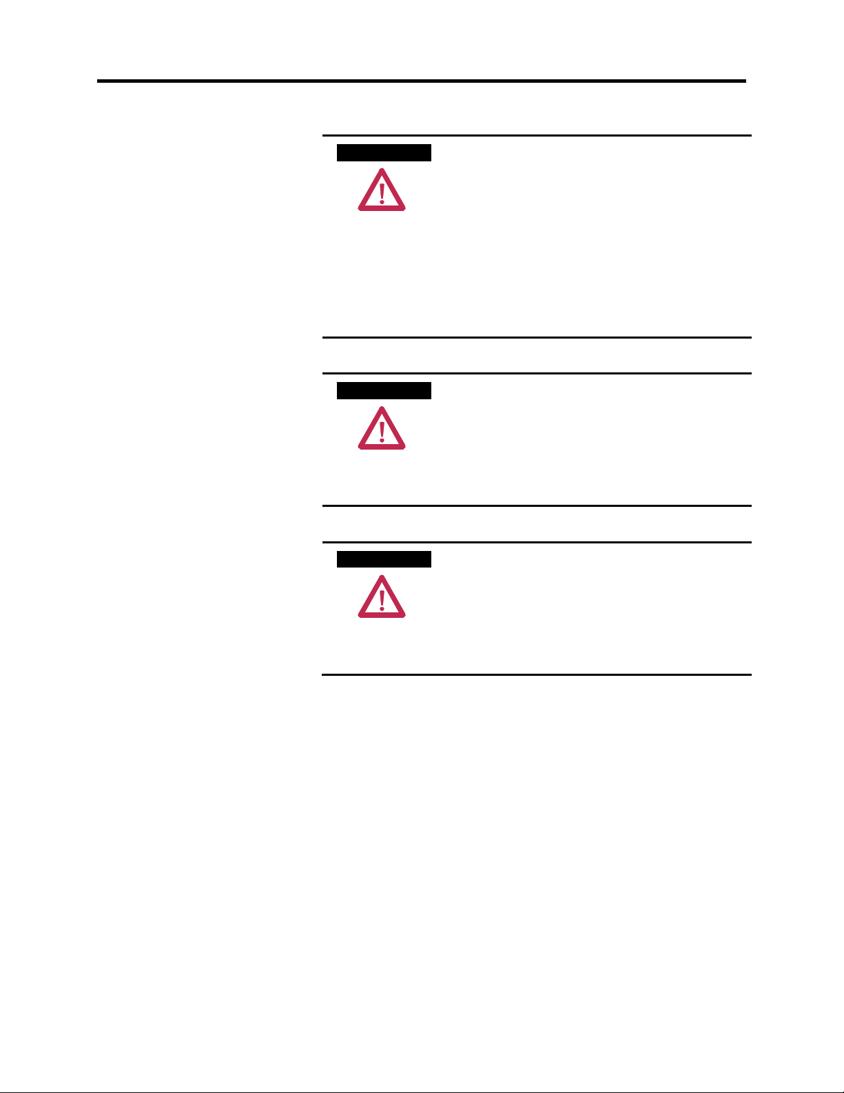
A T T E N T I O NA T T E N T I O N
This drive contains ESD (Electrostatic
Discharge) sensitive parts and assemblies.
Static control precautions are required when
installing, testing, servicing or repairing this
assembly. Component damage may result if
ESD control procedures are not followed. If
you are not familiar with static control
procedures, reference Allen-Bradley
publication 8000-4.5.2, “Guarding Against
Electrostatic Damage” or any other
applicable ESD protection handbook.
A T T E N T I O NA T T E N T I O N
An incorrectly applied or installed drive can
result in component damage or a reduction in
product life. Wiring or application errors,
such as, undersizing the motor, incorrect or
inadequate AC supply, or excessive ambient
temperatures may result in malfunction of the
system.
A T T E N T I O NA T T E N T I O N
Only personnel familiar with the PowerFlex
7000 Adjustable Speed Drive (ASD) and
associated machinery should plan or
implement the installation, start-up and
subsequent maintenance of the system.
Failure to comply may result in personal
injury and/or equipment damage.
Who to Call for Commissioning Rockwell Automation Medium Voltage Support group is
responsible for Commissioning Support and activities in our product
line.
They may be contacted at 519-740-4100, request Medium Voltage
Support – Project Manager.
The support they offer includes, but is not limited to:
– Quoting and Managing Product On-site Start-ups.
– Quoting and Managing Field Modification projects.
– Quoting and Managing Customer in-house and on-site
product training.
7000 “A” Frame 7000A-UM151D-EN-P – March 2013
Page 12

P-4 Preface
7000A-UM151D-EN-P – March 2013 7000 “A” Frame
Page 13

Chapter 1
Overview of Drive
Introduction The PowerFlex® 7000 represents the third generation of medium
voltage drives from Rockwell Automation, and is part of the
PowerFlex family of AC drive products. The Allen-Bradley
PowerFlex® family of Drives incorporates leading-edge technology,
embedded communications, and significant commonality across
multiple platforms, networks, operator interface programming and
hardware.
The PowerFlex 7000 is a general purpose stand alone medium
voltage drive that controls speed, torque, direction, starting, and
stopping of standard induction or synchronous AC motors. It is
intended for use on a host of standard and specialty applications such
as fans, pumps, compressors, mixers, conveyors, kilns, and test
stands. Primary industries for these applications include petrochemical,
cement, mining and metals, forest products, power generation, and
water/waste water.
The PowerFlex 7000 is a global product that adheres to the most
common standards from NEC, IEC, NEMA, UL, and CSA. It is
available with the world’s most common supply voltages at medium
voltage, from 2400-6600 volts.
The design focus is on high reliability, ease of use, and lower total
cost of ownership.
7000 “A” Frame 7000A-UM151D-EN-P – March 2013
Page 14
r
1-2 Overview of Drive
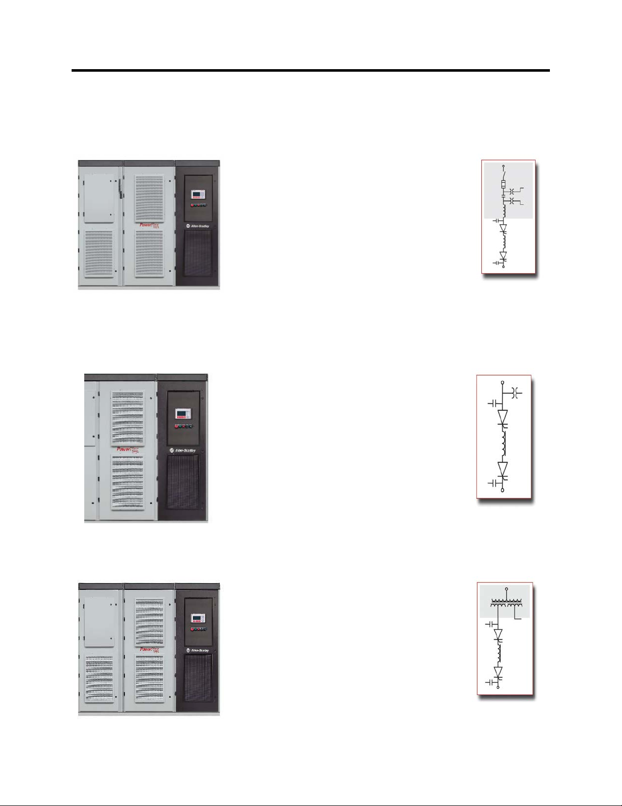
Drive Configurations – PowerFlex 7000 “A” Frame
Configuration #1
Direct-to-Drive
(AFE with DTC DC Link)
Elimination of isolation transformer results in lower
losses and saved space
An integrated system solution for fewer connections
and reduced installation costs
New or existing motors
Small system footprint
3 cables in/3 cables out on entire system for easy
installation
Low line harmonics and high power factor (typical
current THD < 5%, PF > 0.98)
Fan control power and control circuit power
Configuration #2
AFE Rectifier
(Separate isolation transformer)
supplied internally
Input starter optional
Optimum installation flexibility with connection to
indoor or outdoor isolation transformers
Compact packaging for smallest footprint
requirements
New or existing motors
3 cables in/3 cables out for easy installation
Low line harmonics and high power factor (typical
current THD < 5%, PF > 0.98)
Fan control power supplied internally (1-phase
control circuit power supplied by customer,
120V/60 Hz, 110V/50 Hz, 20 amp)
Directto-Drive
(Optional
Input
Starter)
AFE
Rectifier
Configuration #3
AFE Rectifier
(Integral isolation transformer)
An integrated system solution for fewer connections
and reduced installation costs
Small system footprint
New or existing motors
3 cables in/3 cables out for easy installation
Integral cooling fans for VFD and transformer
Low line harmonics and high power factor (typical
current THD < 5%, PF > 0.98)
Fan control power supplied internally (1-phase
control circuit power supplied by customer,
120V/60 Hz, 110V/50 Hz, 20 amp)
Integral
Isolation
Transforme
7000A-UM151D-EN-P – March 2013 7000 “A” Frame
Page 15
Overview of Drive 1-3
L
K
A
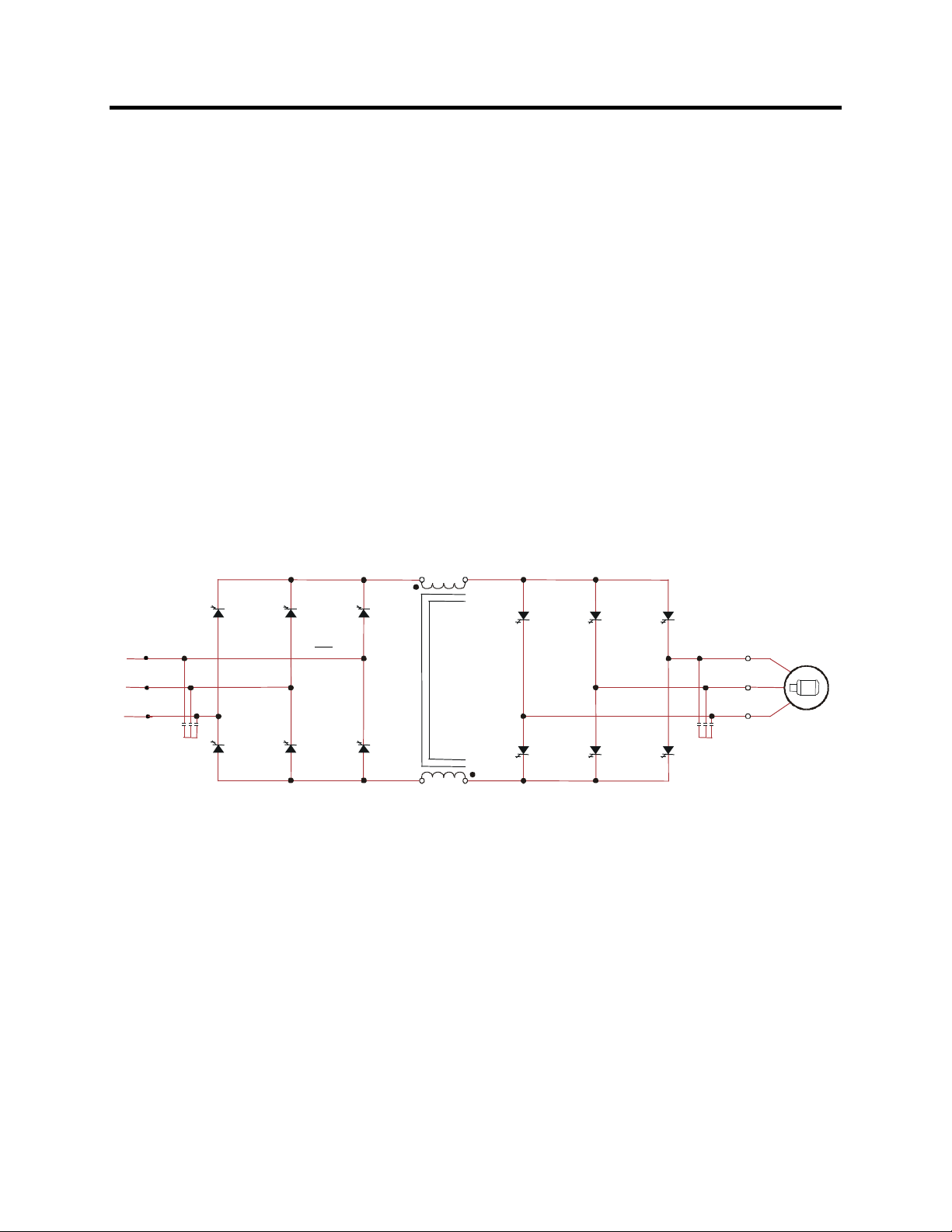
Topology
With 6500 volt PIV rated power semiconductor devices, the number
The PowerFlex 7000 has the additional benefit of inherent
The PowerFlex 7000 utilizes a Pulse Width Modulated (PWM) –
Current Source Inverter (CSI) for the machine side converter as shown
in Figure 1.1. This topology offers a simple, reliable, cost-effective
power structure that is easy to apply to a wide voltage and power
range. The power semiconductor switches used are easy-to-series for
any medium voltage level. Semi-conductor fuses are not required for
the power structure due to the current limiting DC link inductor.
of inverter components is kept to a minimum. For example, only six
inverter switching devices are required at 2400V, 12 at 3300-4160V,
and 18 at 6600V.
regenerative braking for applications where the load is overhauling
the motor, or where high inertia loads need to be slowed down
quickly. Symmetrical Gate Commutated Thyristors (SGCTs) are
used for machine converter switches and line converter switches.
M
INE CONVERTER DCLIN
L+
M+
CHINE CONVERTER
2U (X1)
2V (X2)
2W (X3)
SGCTs
L-
M-
SGCTs
U(T1)
V(T2)
W(T3)
Figure 1.1 – PWM-CSI AC Drive
7000 “A” Frame 7000A-UM151D-EN-P – March 2013
Page 16

1-4 Overview of Drive
Rectifier Designs
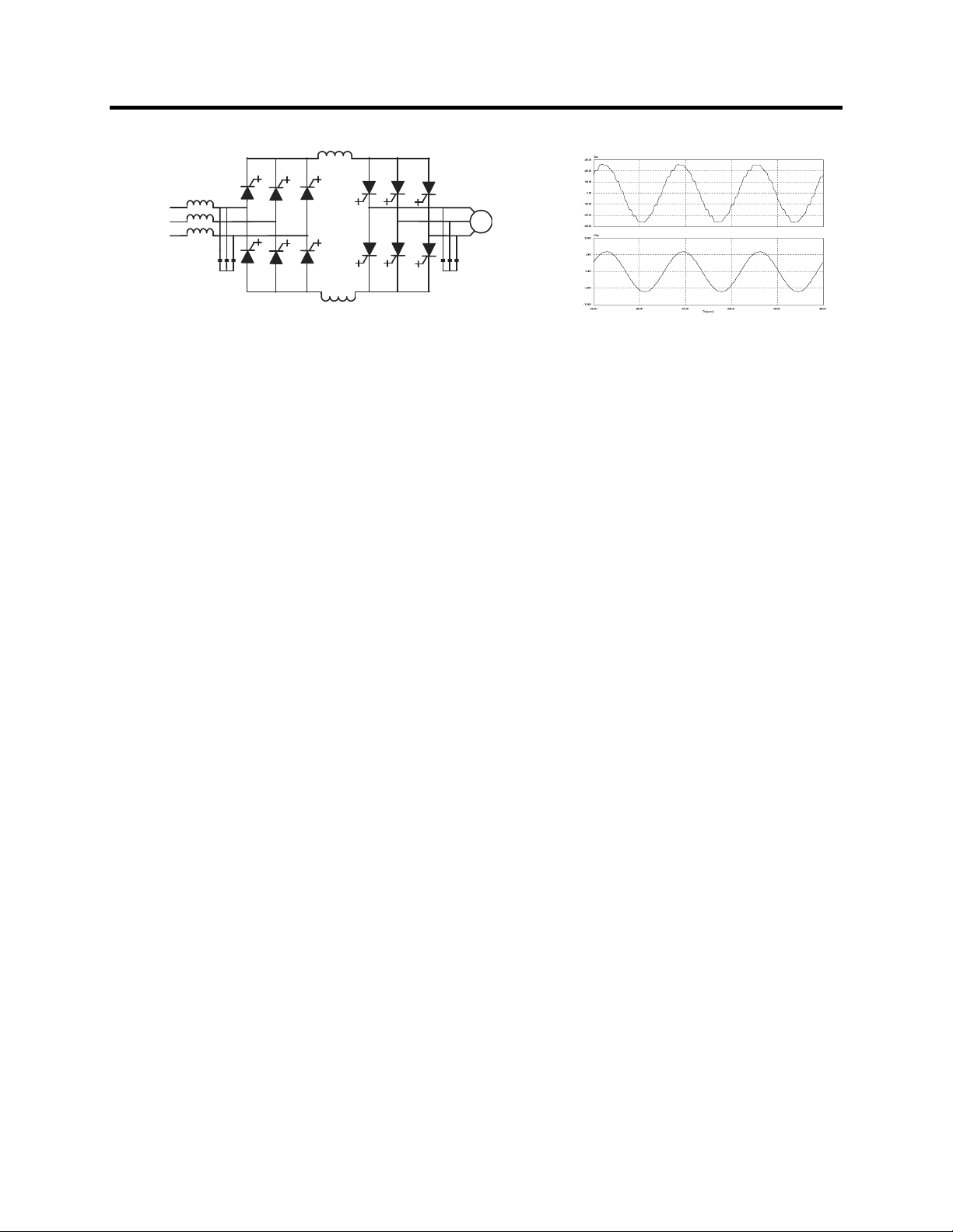
An Active Front-End rectifier is particularly attractive since it does
Many competing technologies in today’s MV market require a multi-
The AFE rectifier requires a switching pattern that complies with
The filter resonant frequency is placed below 300 Hz (for a 60 Hz
The small integral AC line reactor (see Fig. 1.2) provides additional
Active Front-End (AFE) Rectifier
not require an isolation transformer to meet IEEE 519-1992.
winding transformer to mitigate the unwanted harmonics through
cancellation by phase shifting the transformer secondary windings.
Depending on the topology, the transformer can have up to 15 sets of
secondary windings.
Elimination of the isolation transformer reduces capital and
installation costs, saves on valuable floor space, reduces
operating costs and increases overall system efficiency.
similar rules as the inverter. The pattern used for the example shown
in Figure 1.3 is a 42-pulse selective harmonic elimination (SHE)
pattern, which eliminates the 5
th
, 7th and 11th harmonics. The integral
input capacitors are designed to reduce the current harmonics of the
higher order.
system) where no residual harmonics exist. This prevents the
excitation of system harmonic frequencies. Other factors that are
considered when designing the filter are the input power factor and
the requirement on Total Harmonic Distortion (THD) of input
current and voltage waveforms.
filtering and current limiting features to a line side short circuit fault.
The line current and voltage waveforms are also shown in Figure 1.2.
The line current THD is approximately 4.5%, while line-to-line
voltage THD is approximately 1.5%. (THD of line voltage is a
function of system impedance.) Input power factor with the AFE
rectifier is near unity throughout a typical operating speed range for
variable torque loads.
7000A-UM151D-EN-P – March 2013 7000 “A” Frame
Page 17
Overview of Drive 1-5
a)
b)
a) Line current
Figure 1.2 – AFE rectifier and its input current/voltage waveforms
b) Line-to-line voltage at PCC
The AFE rectifier can be used in conjunction with a rectifier duty
isolation transformer or with an AC line reactor (as shown in Figure 1.2).
Isolation transformers are available:
1) Integral to the Drive
2) Remote indoor dry type, or
3) Outdoor oil-filled type
This allows for maximum flexibility in dealing with floor space,
installation cost and control room air conditioner loading.
“Direct-to-Drive” Technology Reduce the cost, size and weight of your medium voltage drive
system with the Allen-Bradley PowerFlex 7000 with Direct-to-Drive
technology. This is the first and only technology that allows you to
directly connect a medium voltage drive to utility power without the
requirement of an isolation transformer. Isolation transformers with
multiple secondary windings are required for traditional AC drives to
address line-side harmonic concerns and common mode voltage.
However, typical isolation transformers are large, heavy, costly,
complex and inefficient. Direct-to-Drive technology combines an
Active Front End (AFE) rectifier to dramatically lower line-side
harmonics and a patented DC link inductor to address common mode
voltage at its source. By addressing harmonics and common mode
voltage, the isolation transformer becomes redundant. This reduces
system complexity to maximize uptime and increases system
efficiency to lower operational costs. Exceptional output voltage and
current waveforms, true of our entire product line, make this ideal for
retrofit applications and allow the use of standard motors for new
applications.
7000 “A” Frame 7000A-UM151D-EN-P – March 2013
Page 18
0
A
1-6 Overview of Drive
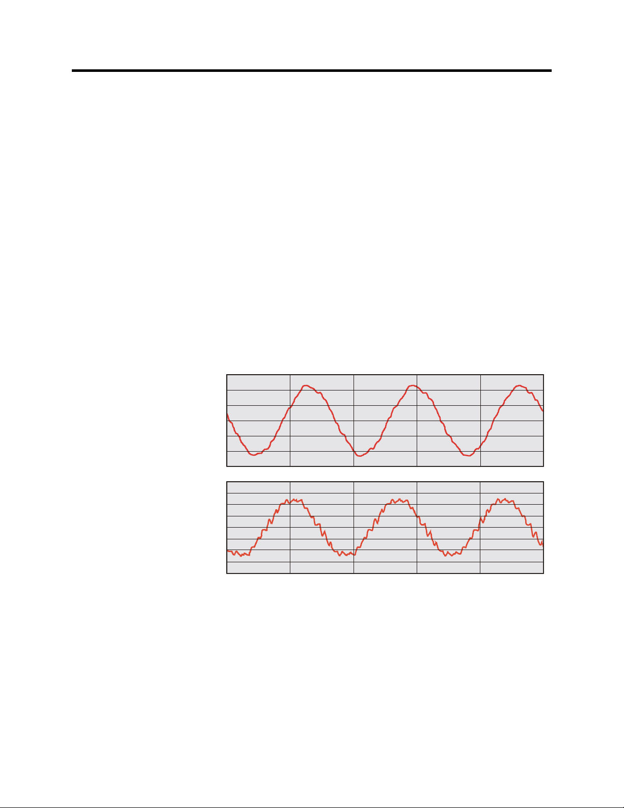
Motor Compatibility The PowerFlex 7000 achieves near sinusoidal current and voltage
waveforms to the motor, resulting in no significant additional heating
or insulation stress. Temperature rise in the motor connected to the
VFD is typically 3 °C (5.4 °F) higher compared to across-the-line
operation. Voltage waveform has dv/dt of less than 10 volts per
microsecond. Reflected wave and dv/dt issues often associated with
VSI (voltage source inverter) drives do not exist with the PowerFlex
7000. Typical motor waveforms are shown in Figure 1.3. These
motor friendly waveforms are achieved by utilizing a selective
harmonic elimination (SHE) pattern in the inverter to eliminate
major order harmonics, in conjunction with a small output capacitor
(integral to the drive) to eliminate harmonics at higher speeds.
Standard motors are compatible without de-rating, even on retrofit
applications.
Motor cable distance is virtually unlimited. This technology is capable
of controlling motors up to 15 km (9.3 miles) away from the drive.
rms
300.00
200.00
100.00
Motor current
Motor voltage
-10.00K
0.00
-100.00
-200.00
-300.00
10.00K
7.50K
5.00K
2.50K
0.00K
-2.50K
-5.00K
-7.50K
Vrms
100.00
110.00
120.00 130.00
TIME (ms)
140.00
150.0
Figure 1.3 – Motor waveform @ full load, full speed
7000A-UM151D-EN-P – March 2013 7000 “A” Frame
Page 19
LIN
ECONVERTERDCLIN
K
M
ACHIN
ECONVERTE
A
1
1
A
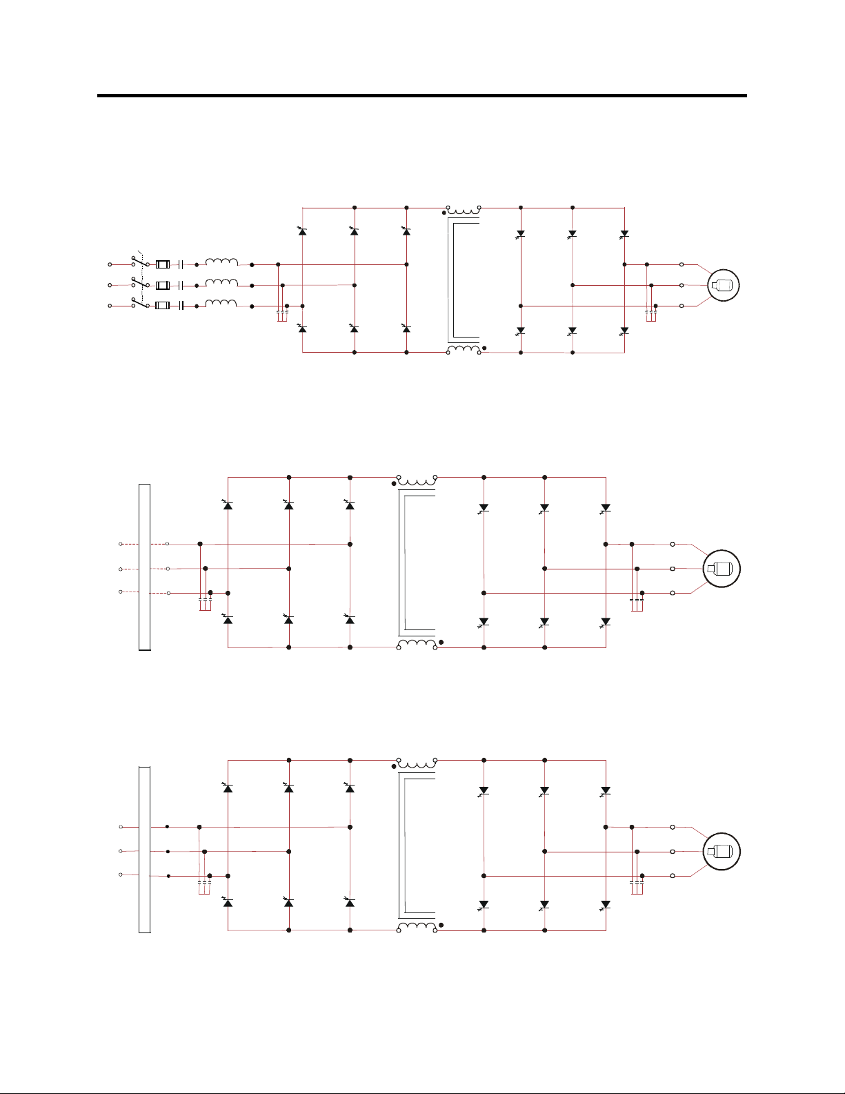
Simplified Electrical Drawings – 2400V with AFE Rectifier
L+
Overview of Drive 1-7
M+
R
SGCTs
L1
L2
L3
LR
L-
M-
2400 Volt – AFE Rectifier, Configuration #1 – Direct-to-Drive
(Configurations without Integral Input Starter are available)
REMOTE
ISTX
1U
1V
W
2U (X1)
2V (X2)
2W (X3)
LINE CONVERTER DC LINK
SGCTs
L+
M+
CHINE CONVERTER
M
SGCTs
SGCTs
U(T1)
V(T2)
W(T3)
U(T1)
V(T2)
W(T3)
L-
M-
2400 Volt – AFE Rectifier, Configuration #2 – Separate Isolation Transformer
INTEGRAL
ISTX
1U
1V
W
2U (X1)
2V (X2)
2W (X3)
LINE CONVERTER DC LINK
SGCTs
L+
M+
L-
M-
CHINE CONVERTER
M
SGCTs
U(T1)
V(T2)
W(T3)
2400 Volt – AFE Rectifier, Configuration #3 – Integral Isolation Transformer
7000 “A” Frame 7000A-UM151D-EN-P – March 2013
Page 20
LIN
ECONVERTERDCLIN
K
M
ACHIN
ECONVERTE
D
C
K
MAC
1
ECONV
ERTERD
C
K
MAC
ECONV
ERTE
1-8 Overview of Drive
Simplified Electrical Drawings – 3300/4160V with AFE Rectifier
L+
M+
R
SGCTs
L1
L2
L3
LR
L-
M-
SGCTs
3300/4160 Volt – AFE Rectifier, Configuration #1 – Direct-to-Drive
(Configurations without Integral Input Starter are available)
1U
1V
1W
REMOTE
ISTX
2U (X1)
2V (X2)
2W (X3)
LINECONVERTER
SGCTs
LIN
L+
M+
HINECONVERTER
SGCTs
U(T1)
V(T2)
W(T3)
U(T1)
V(T2)
W(T3)
L-
M-
3300/4160 Volt – AFE Rectifier, Configuration #2 – Separate Isolation Transformer
INTEGRAL
ISTX
LIN
SGCTs
1U
1V
W
2U (X1)
2V (X2)
2W (X3)
LIN
L+
M+
L-
M-
SGCTs
HIN
R
U (T1)
V (T2)
W (T3)
3300/4160 Volt – AFE Rectifier, Configuration #3 – Integral Isolation Transformer
7000A-UM151D-EN-P – March 2013 7000 “A” Frame
Page 21
LIN
ECONVERTERDCLIN
K
M
ACHIN
ECONVERTE
D
C
K
MAC
NECONVE
RTERD
CLIN
K
ACHINECONVE
RTE
R
Simplified Electrical Drawings – 6600 V with AFE Rectifier
L+
M+
SGCTs
Overview of Drive 1-9
R
SGCTs
L1
L2
L3
LR
L-
M-
6600 Volt – AFE Rectifier, Configuration #1 – Direct-to-Drive
(Configurations without Integral Input Starter are available)
HINECONVERTER
SGCTs
1U
1V
1W
REMOTE
ISTX
LINECONVERTER
SGCTs
2U (X1)
2V (X2)
2W (X3)
LIN
L+
M+
L-
M-
6600 Volt – AFE Rectifier, Configuration #2 – Separate Isolation Transformer
INTEGRAL
ISTX
LI
SGCTs
L+
M+
M
SGCTs
U(T1)
V(T2)
W(T3)
U (T1)
V(T2)
W(T3)
1U
1V
1W
2U (X1)
2V (X2)
2W (X3)
L-
M-
U(T1)
V(T2)
W(T3)
6600 Volt – AFE Rectifier, Configuration #3 – Integral Isolation Transformer
7000 “A” Frame 7000A-UM151D-EN-P – March 2013
Page 22
1-10 Overview of Drive
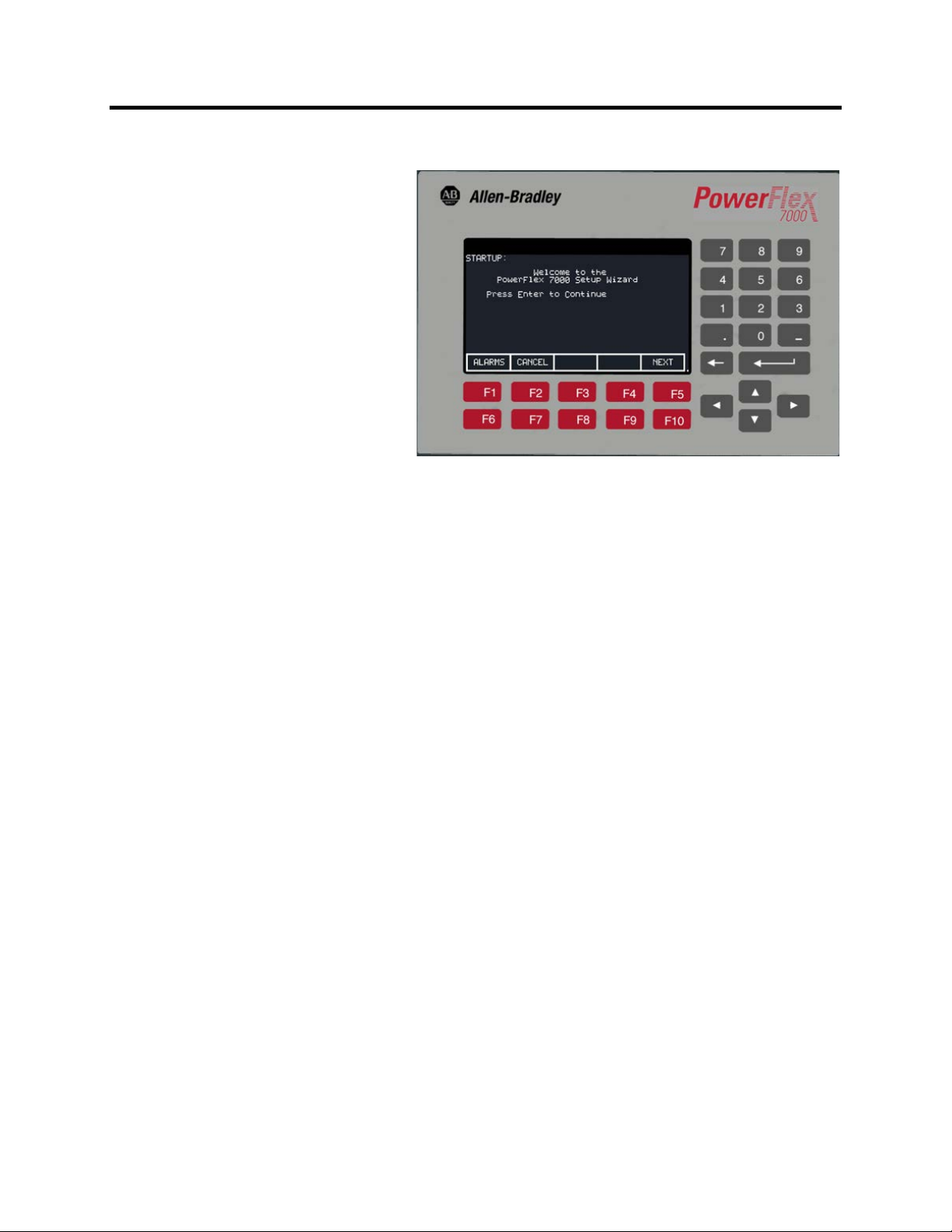
Operator Interface
Figure 1.4 – PowerFlex 7000 Operator interface terminal
The operator interface terminal features a 16-line, 40-character, pixel
based LCD display that makes text and graphics easy to read. Bar
chart meters are configurable for common process variables
including speed, voltage and load.
Everything is user friendly about the PowerFlex 7000 operator interface
terminal including the greeting on the opening screen. The terminal
is designed for the greatest ease of use for start-up, monitoring and
troubleshooting. The setup wizard helps the user to set the required
parameter menus by asking questions or prompting selections for
desired operation. Warnings and comments appear complete with
help text to keep the user on the right track. The setup wizard combined
with the auto-tuning feature allows the drive to be tuned to the motor
and load as quickly and accurately as possible, resulting in fast startups, smooth operation, and less down time.
7000A-UM151D-EN-P – March 2013 7000 “A” Frame
Page 23
Chapter 2
Drive Installation
Safety and Codes
W A R N I N GW A R N I N G
General Handling Procedures Refer to “General Handling Procedures for PowerFlex 7000 Medium
Voltage Drives”, publication no. 7000-IN002_-EN-P supplied in the
drive shipment (affixed to the drive). Additional copies can be
ordered through your local Rockwell Automation Sales office.
Drive Storage If it is necessary to store the drive, be certain to store in a clean dry
dust free area.
Storage temperature should be maintained between -40°C and 70°C
(-40°F and 185°F). If storage temperature fluctuates or if humidity
exceeds 95%, space heaters should be used to prevent condensation.
The drive should be stored in a heated building having adequate air
circulation. The drive must never be stored outdoors.
The Canadian Electrical Code (CEC), National
Electrical Code (NEC), or local codes outline
provisions for safely installing electrical
equipment. Installation MUST comply with
specifications regarding wire type, conductor
sizes, branch circuit protection and disconnect
devices. Failure to do so may result in personal
injury and/or equipment damage.
7000 “A” Frame 7000A-UM151D-EN-P – March 2013
Page 24

2-2 Drive Installation
Siting of the Drive Site Considerations
The standard environment in which the equipment is designed to
operate is:
• Elevation above sea level less than 1000 meters (3250 feet)
• Ambient air temperature between 0°C (32°F) and 40°C (104°F)
• Relative humidity of the air not to exceed 95% non-condensing
For the equipment to operate in conditions other than those specified
consult the local Rockwell Automation Sales office.
The equipment requires the following site conditions:
(A) Indoor installation only, no dripping water or other fluids
(B) Clean air for cooling requirements
(C) Level floor for anchoring the equipment. Refer to dimension
drawings for the location of the anchoring points.
(D) The room in which the equipment is located must allow for full
opening of the doors of the equipment, typically 1200 mm
(48 inches). Also, allowances have to be made for clearance
for fan removal. This fan allowance must be greater than 700
mm (27.5 inches) above the drive.
or
Dimension drawings can be obtained by contacting the local
Rockwell Automation Sales office. The equipment does not
require rear access for servicing.
(E) Allowance must be made for the stream of cooling air which
exits the drive at the top. The flow of cooling air into and out
the drive must be kept clear and uninhibited.
(F) The room in which the equipment is located must be large
enough to accommodate the thermal losses of the equipment
since air conditioning may be required; the ambient
temperature must not exceed that for which the equipment is
rated. The heat created by the drive is directly proportional to
the power of the motor being driven and the efficiency of
equipment within the room. If thermal load data is required
contact the Rockwell Automation Sales office.
(G) The area in which the drive is located should be free of radio
frequency interference such as encountered with some welding
units. This may cause erroneous fault conditions and shut
down the drive.
7000A-UM151D-EN-P – March 2013 7000 “A” Frame
Page 25
Drive Installation 2-3
(H) The equipment must be kept clean. Dust in the equipment
decreases system reliability and inhibits cooling.
(I) Power cable lengths to the motor are virtually unlimited due to
the near sinusoidal voltage and current waveforms. Unlike
voltage source drives, there are no capacitive coupling, dv/dt,
or peak voltage issues that can damage the motor insulation
system. The topology utilized in the PowerFlex 7000 medium
voltage AC drive does not produce dv/dt or peak voltage
problems, and has been tested with motors located up to 15
kilometers from the drive.
(J) Only personnel familiar with the function of the drive should
have access to the equipment.
(K) The drive is designed for front access and should be installed
with adequate and safe clearance to allow for total door
opening. The back of the unit may be placed against a wall
although some customers prefer back access also.
A T T E N T I O NA T T E N T I O N
Generator Note:
A T T E N T I O NA T T E N T I O N
An incorrectly applied or installed drive can
result in component damage or a reduction in
product life. Ambient conditions not within
the specified ranges may result in
malfunction of the drive.
Verify that the load is not turning due to the
process. A freewheeling motor can generate
voltage that will be back-fed to the equipment
being worked on.
7000 “A” Frame 7000A-UM151D-EN-P – March 2013
Page 26

2-4 Drive Installation
Installation When the drive has been placed at its installation area, the lag bolts
that fasten the shipping skid to the drive must be removed. The drive
is moved off the shipping skid and the shipping skid can be
discarded.
Position the drive in its desired location. Verify that the drive is on a
level surface and that the position of the drive will be vertical when
the anchor bolts are installed.
The location of the anchor points is provided with the dimension
drawing of the drive.
Install and tighten the anchor bolts. (M12 or ½” hardware required).
Engineering bolt systems are required for seismic requirements.
Consult factory.
Remove the top lifting angles, retain the hardware.
Install the hardware from the lifting angles in the tapped holes at the
top of drive; this prevents leakage of cooling air as well as keeping
dust out of the equipment.
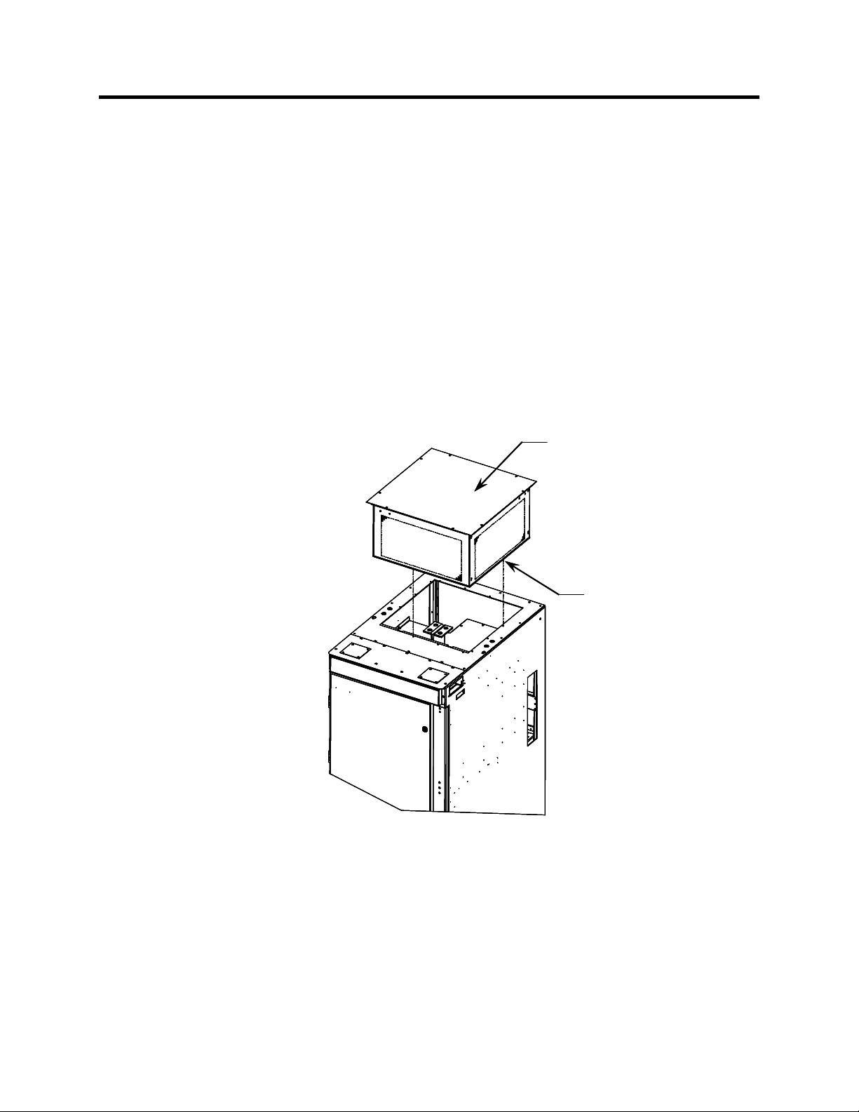
Installation of Exhaust Air Hood
On the top of the cabinet with the cooling fan, a sheet metal exhaust
hood is to be installed. The components to make up the exhaust
hood have been packaged and shipped with the drive. (For drives
with an acoustic hood, the components are shipped assembled. See
Figure 2.2)
The first step is to remove the protective plate covering the fan
opening on the drive. It is a flat cover plate bolted to the top plate.
Remove the bolts and plate and set aside for re-use.
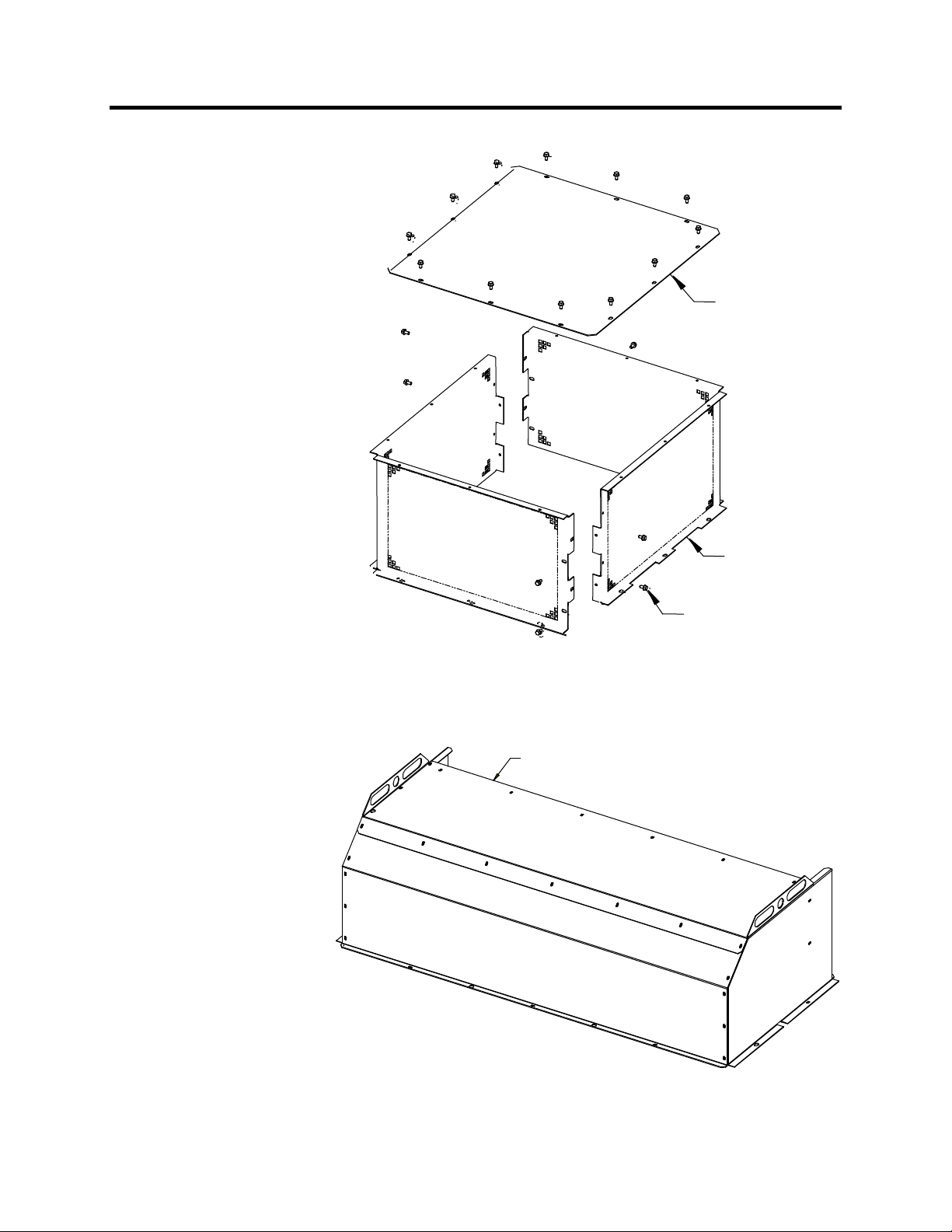
Secondly, loosely assemble the two L-shaped panel components
shipped with the drive as per Figure 2.1.
7000A-UM151D-EN-P – March 2013 7000 “A” Frame
Page 27
Drive Installation 2-5
Flat plate
(Quantity = 1)
Figure 2.1 – Fan Hood Assembly
All the components are shipped assembled.
Exhaust hood panels
(Quantity = 2)
M6 thread forming screws
(Quantity = 20)
Figure 2.2 – Acoustic Fan Hood Assembly
7000 “A” Frame 7000A-UM151D-EN-P – March 2013
Page 28
2-6 Drive Installation
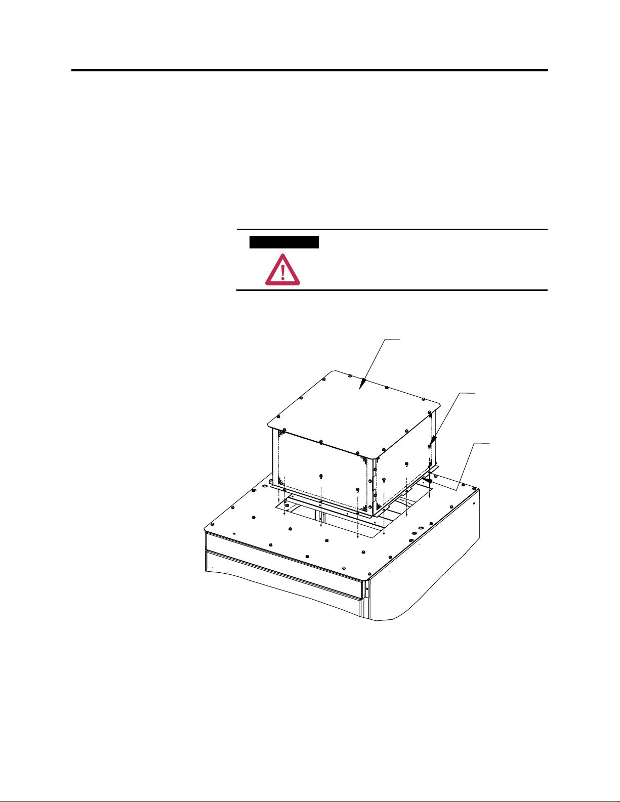
Installation (cont.) Locate the exhaust hood on top of the cabinet per Figure 2.3 and re-
install the original cover plate previously set aside. (Care must be
taken that the notches on the bottom flange are oriented toward the
sides of the drive). Affix assembly to the drive top plate. Tighten all
hardware.
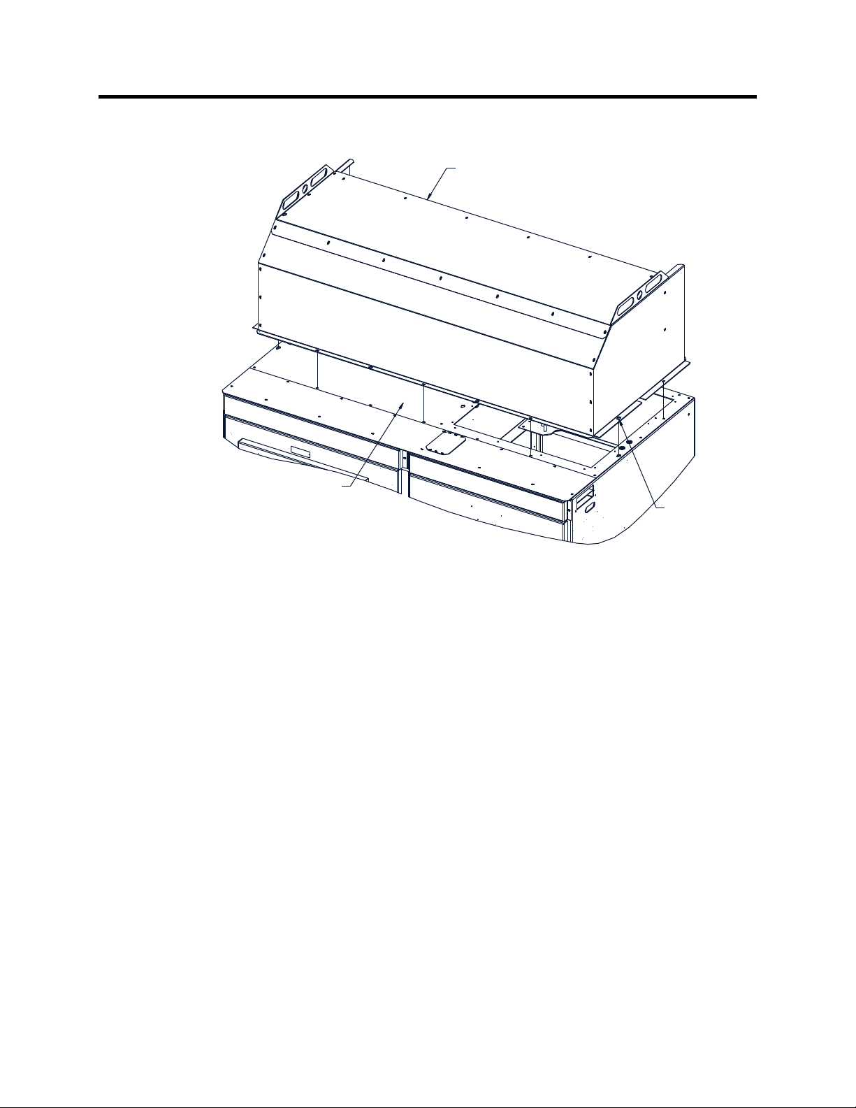
For drives with an acoustic hood (shown in Figure 2.2), locate the
exhaust hood (refer to Figure 2.4).
A T T E N T I O NA T T E N T I O N
Any screws that are accidentally dropped in
the equipment must be retrieved as damage
or injury may occur.
Assembled Exhaust Hood
M6 Screw
(Quantity = 12)
Ensure notch
orientation
to sides
Figure 2.3 – Fan Hood Installation
7000A-UM151D-EN-P – March 2013 7000 “A” Frame
Page 29
w
Drive Installation 2-7
Assembled Acoustic
Exhaust Hood
Top Plate for Converter
and Common Mode Choke/
DC Link Cabinet
Figure 2.4 – Acoustic Fan Hood Installation
M6 Screw.
Remove Existing Scre
and reinsert with Hood.
(Quantity = 11)
7000 “A” Frame 7000A-UM151D-EN-P – March 2013
Page 30
2-8 Drive Installation
Installation (cont.) Installation of Integral Transformer Cooling Fan
1. Remove the protective plate covering the fan opening on the top
of Isolation Transformer cabinet and discard.
2. Locate the cooling fan on top of the cabinet. Position it over the
opening and align the mounting holes and wire harness
connections.
3. Affix the fan to the drive top plate with the M6 thread forming
screws provided.
4. Connect the fan wire harness to fan.
Assembled Exhaust Hood
Assembled Exhaust Hood
M6 Screw
M6 Screw
(Qty = 12)
(Qty = 12)
Figure 2.5 – Fan Installation for Integral Isolation Transformer
7000A-UM151D-EN-P – March 2013 7000 “A” Frame
Page 31

T
T
r
A
Drive Installation 2-9
Neutral Resistor Assembly
op Plate for Neutral
Resistor Housing
Ground Resistor
Hood here
op Plate for Converter
and Common Mode
Choke Cabinet
900 mm Converter –
800 mm Common Mode Choke Cabinet
ttach ground
to top plate
Line Filter
Capacitors
Neutral Resistor Assembly
Refer to Electrical Dra wings
to veri fy cable rating
to connect neutral
resistor assembly.
Motor Filte
Capacitors
Figure 2.6 – Hood Assembly for Neutral Resistor
7000 “A” Frame 7000A-UM151D-EN-P – March 2013
Page 32

2-10 Drive Installation
Assembled Acoustic
Exhaust Hood
Hood Ground Stud
Remove existing screw
and reinsert with Hood.
Ground Exhaust Hood here.
(Use Green M6 Screw)
M6 Screw.
(Quantity = 11)
M6 Screw
(Quantity = 6)
Neutral Resistor Assembly
Top Plate for Converter
and Common Mode
Choke/DC Link Cabinet
Figure 2.7 – Acoustic Hood Assembly for Neutral Resistor
Installation of Neutral Resistor Assembly
(Drives with Common Mode Chokes)
On top of the converter cabinet, a sheet metal enclosure containing
power resistors is to be installed.
1. Locate the resistor assembly on top of the cabinet as shown in
Figure 2.6. (For acoustic hood assembly, refer to Figure 2.7.)
2. Affix the assembly to the top plate using M6 thread forming
screws provided.
3. Remove the top plate of the resistor assembly to permit access to
the wiring connection points.
4. Connect the resistor wiring and per the electrical diagram
provided with the drive, a typical connection diagram is shown
in Figure 2.6. Ensure that the resistor wiring is routed through
the hole having a plastic bushing to protect the wire insulation.
The neutral resistor assembly housing has a ground connection
that is to be connected to the top plate of the drive.
5. Re-install the top plate of the neutral resistor housing.
7000A-UM151D-EN-P – March 2013 7000 “A” Frame
Page 33

Drive Installation 2-11
Cabinet Layout and
Dimensional Drawings
of Drive
The following dimension drawing is a sample and may not accurately
detail your drive. It is provided here to give you a general overview
of a typical drive.
The Dimensional Drawings are order specific and will show the
information outlined.
The dimension drawing provides important information for the
installation of the equipment.
The FLOOR PLAN shows:
• the locations for anchoring the equipment to the floor (balloon D)
• size and location of openings for bottom power cable entry
(balloons A and B)
• size and location of openings for bottom control wiring entry
(balloon C)
The ROOF PLAN shows:
• size and location of openings for top power cable entry (balloons
A and B)
• size and location of openings for top control wiring entry
(balloon C)
• minimum aisle clearance in front of equipment (balloon M)
The Front View shows:
• minimum clearance required at top of drive for fan maintenance
(balloon K)
7000 “A” Frame 7000A-UM151D-EN-P – March 2013
Page 34

2-12 Drive Installation
PowerFlex 7000 “A” Frame Dimensional Drawing
SAMPLE
Note: Contact Factory for Seismic Mounting Information.
7000A-UM151D-EN-P – March 2013 7000 “A” Frame
Page 35

Drive Installation 2-13
Drive Layout The following diagrams are presented to show the typical layout of
the three main configurations of the PowerFlex 7000 “A” Frame Drive.
Configuration #1
Direct-to-Drive
(AFE with DTC DC Link)
Line Reactor/Starter
Cabling Catinet
Converter Cabinet Control/DC Link/Fan Cabinet
Figure 2.8 – Direct-to-Drive (AFE with DTD DC Link)
7000 “A” Frame 7000A-UM151D-EN-P – March 2013
Page 36

2-14 Drive Installation
Configuration #2
AFE Rectifier
(Separate Isolation Transformer)
Cabling Cabinet Converter Cabinet Control/DC Link/Fan Cabinet
Figure 2.9 – AFE Rectifier (Separate Isolation Transformer)
7000A-UM151D-EN-P – March 2013 7000 “A” Frame
Page 37

Configuration #3
AFE Rectifier
(Integral Isolation Transformer)
Drive Installation 2-15
Isolation Transformer
and Cabling Catinet
Converter Cabinet Control/DC Link/Fan Cabinet
Figure 2.10 – AFE Rectifier (Integral Isolation Transformer)
7000 “A” Frame 7000A-UM151D-EN-P – March 2013
Page 38

C
2-16 Drive Installation
Cabling Cabinet #1 The cabling cabinet of the drive with integral line reactor and input
starter is located in the left-hand section. The mounting and location
of the line reactor and input starter are shown along with customer
cable termination locations. The circulating fans for the cabinet are
Note: This cabinet is also available without integral starter (see
located on top.
Figure 2.13). The width of the cabinet changes as a function of the
drive voltage ratings.
Line Cable Terminations
(behind Disconnect Switch)
Fused Disconnect Switch
ontrol Power Transformer
Motor Cable Terminations
(Hall Effect Sensors behind)
Disconnect Switch Operating Handle
Vacuum Contactor Assembly
Control Power Transformer Fuses
AC Line Reactor
Figure 2.11 – Cabling Cabinet for Configuration #1 with Input Starters
7000A-UM151D-EN-P – March 2013 7000 “A” Frame
Page 39

s
Cabling Cabinet #1
Line Cable
Terminations
Drive Installation 2-17
Low Voltage
Compartment
Hall Effect Sensor
Current
Transformers
Control Power
Transformer Fuses
Motor Cable
Terminations
AC Line Reactor
Figure 2.12 – Cabling Cabinet for Configuration #1 without Input Starters
7000 “A” Frame 7000A-UM151D-EN-P – March 2013
Page 40

r
2-18 Drive Installation
Cabling Cabinet #2
Cabling cabinet #2 is located in the left hand section and shows the
medium voltage area for customer cable terminations, three phase
fan power transformer, and fuse assemblies for transformer.
Low Voltage Wireway
Current Transformer
Line Terminals
Current Transformer
Control Power
Transformer Fuses
Hall Effect Sensor
Motor Cable Terminations
Hall Effect Sensor
Fan Control Power Transforme
Figure 2.13 – Cabling Cabinet for Configuration #2
7000A-UM151D-EN-P – March 2013 7000 “A” Frame
Page 41

Drive Installation 2-19
Bac
F
u
sin
g
Cabling Cabinet #3 The cabling cabinet of the drive with integral isolation transformer is
located in the left-hand section. The mounting and location of the
isolation transformer is shown along with customer cable termination
locations. The cooling fan for the isolation transformer is located on top.
an Ho
Top Cable Entry
and Exit locations
Ground Bus
Hall Effect Sensors
Line Terminals
Load Terminals
Current Transformers
(CT)
Integral Isolation
Transformer
k)
(
Side View Front View
(Front)
Bottom Cable Entry
and Exit locations
Figure 2.14 – Cabling Cabinet for Configuration #3
7000 “A” Frame 7000A-UM151D-EN-P – March 2013
Page 42

2-20 Drive Installation
Converter Cabinet The converter cabinet for all configurations of the PowerFlex 7000
“A” Frame drive is located in the middle section. The mounting and
location of Inverter / rectifier modules are shown along with gate
drive power supplies and voltage sensing modules.
Note: The width of the inverter / rectifier modules changes as a
function of the drive voltage ratings (2400-6600V).
Inverter Modules
Isolated Gate Drive
Power Supplies
(IGDPS)
Rectifier Modules
Voltage Sensing Boards
Figure 2.15 – Major Components of the Converter Cabinet
(3300/4160V version shown)
7000A-UM151D-EN-P – March 2013 7000 “A” Frame
Page 43

Drive Installation 2-21
Control / DC Link / Fan
The control / DC link / fan cabinet for all configurations of the
Cabinet
Note: The control / DC link / fan cabinet has the same layout for all
PowerFlex 7000 “A” Frame drive is located in the right section. The
mounting and location of the DC link inductor, line / load side
capacitors, and main cooling fan are shown behind the low voltage
control tub.
drives at 2400-6600 volt ratings.
Fan
Inlet Ring
DC Link
Inductor
Grounding
Network
Capacitors
Motor Filter
Capacitor
Line Filter Capacitor
Figure 2.16 – Major Components of Control / DC Link / Fan Cabinet
(with low voltage control tub removed)
7000 “A” Frame 7000A-UM151D-EN-P – March 2013
Page 44

y
2-22 Drive Installation
The low voltage control tub is mounted in front of the DC link
Low Voltage Control Tub
(Located in Control / DC Link /
Fan Cabinet)
inductor in DC link / fan cabinet of the drive. Refer to Chapter 6,
Component Definition and Maintenance, for complete content details
of the low voltage section.
Note: The low voltage control tub has the same layout for all
PowerFlex 7000 “A” Frame drive ratings.
AC to DC
Pioneer
Power Suppl
Analog
Control
Board
Drive
Processor
Module
Board
Hinged
Panel
(Closed)
Fiber Optic
Interface
Boards
DC to DC
Power Supply
Hinged Panel (Open)
Figure 2.17 – Location of Low Voltage Control Tub (Pioneer Power Supply)
7000A-UM151D-EN-P – March 2013 7000 “A” Frame
Page 45

y
Drive Installation 2-23
AC to DC
Cosel
Power Suppl
Analog
Control
Board
Drive
Processor
Module
Board
Hinged
Panel
(Closed)
Fiber Optic
Interface
Boards
DC to DC
Power Supply
Hinged Panel (Open)
Figure 2.18 – Location of Low Voltage Control Tub (Cosel Power Supply)
7000 “A” Frame 7000A-UM151D-EN-P – March 2013
Page 46

2-24 Drive Installation
IEC Component and
PowerFlex 7000 electrical drawings use conventions that are based
Device Designations
on IEC (International Electrotechnical Commission) standards, while
remaining basically compatible with North American ANSI
(American National Standards Institute) standards. The symbols
used to identify components on the drawings are international and a
full listing of the symbols is given as part of each PowerFlex 7000
electrical drawing (ED) set. The device designations used on the
drawings and labeling are also listed with explanations on each
drawing set.
Wiring identification uses a source/destination wire number
convention on point to point multi-conductor wiring and in situations
where the system is warranted. The wire-numbering system of
unique, single numbers for multi-drop and point to point wiring
continues to be used for general control and power wiring. Wiring
that connects between the sheets or that ends at one point and starts
at another point on a drawing has an arrow and drawing reference to
indicate the ongoing connection. The drawing reference indicates
the sheet and the X/Y coordinates of the continuation point. The
reference system is explained on a sheet in each drawing set. The
unique wire numbering system serves as confirmation that the
correct wire is being traced from sheet to sheet or across a drawing.
Wires in multi-conductor cables are typically identified by color
rather than by number. The abbreviations used to identify the colors
on the drawings are fully identified on a sheet in the drawing set.
Power Wiring Selection The following tables identify general wire selections that will be
encountered when installing the PowerFlex 7000 “A” Frame drive
line-up.
General Notes:
Adherence to the following recommended field power cabling
insulation levels for medium voltage drives will help to ensure
trouble-free start-up and operation. The cable insulation level must
be increased over that which would be supplied for an Across-theline application with the same rated line to line voltage.
Either shielded or unshielded cable may be used based on the criteria
considered by the distribution system designer. However, NEC
requires shielded cables for installations above 2 kV.
7000A-UM151D-EN-P – March 2013 7000 “A” Frame
Page 47

Drive Installation 2-25
Cable Insulation
The cable insulation requirements for the PowerFlex 7000 “A”
Frame drive are given in the tables below.
A T T E N T I O NA T T E N T I O N
Voltage ratings shown in the following
tables are peak line-to-ground. Some cable
manufacturers rate voltage line-to-line RMS.
Ensure the cable meets the rating specified
in the following tables.
Cable Insulation Requirements for AFE Drives with Separate Isolation Transformer
System Voltage (V, RMS)
Cabling from secondary side of Isolation Transformer to input of VFD
Cable Insulation Requirements for “Direct-to-Drive” Technology or Integral
Isolation Transformer
System Voltage (V, RMS)
2400
3000
3300
4160
6000
6300
6600
2400
3000
3300
4160
6000
6300
6600
Cable Insulation Rating (kV)
(Maximum Peak Line-to-Ground)
Machine Side
≥ 4.1 ≥ 2.2
≥ 5.12 ≥ 2.75
≥ 5.63 ≥ 3.0
≥ 7.1 ≥ 3.8
≥ 10.8 ≥ 5.5
≥ 11.4 ≥ 5.8
≥ 11.8 ≥ 6.0
Cable Insulation Rating (kV)
(Maximum Peak Line-to-Ground)
Line Side Machine Side
≥ 2.2 ≥ 2.2
≥ 2.75 ≥ 2.75
≥ 3.0 ≥ 3.0
≥ 3.8 ≥ 3.8
≥ 5.5 ≥ 5.5
≥ 5.8 ≥ 5.8
≥ 6.0 ≥ 6.0
7000 “A” Frame 7000A-UM151D-EN-P – March 2013
Page 48

A
2-26 Drive Installation
The following table identifies general wire categories that will be encountered when installing the
PowerFlex 7000 “A” Frame Drive. Each category has an associated wire group number that is used in the
following sections to identify the wire to be used. Application and signal examples along with the
recommended type of cable for each group are provided. A matrix providing the recommended minimum
spacing between different wire groups run in the same tray or separate conduit is also provided.
For Tray: Recommended spacing between different wire groups in the same tray.
Wire
Category
Power
Control
Signal
Wire
Group
Application
1
2
3
4
5
6
AC Power
(> 600V AC)
AC Power
(TO 600V AC)
115V AC
or 115V DC
Logic
115V AC
Between
Power
24V AC
or 24V DC
Logic
Analog Signals
DC Supplies
Digital
(Low Speed)
Digital
(High Speed)
Signal
Example
2.3 kV, 3∅
AC Lines
480V, 3∅
Relay Logic
PLC I/O
Power Supplies
Instruments
PLC I/O
5-24V DC
Supplies
Power Supplies
TTL Logic Level
Pulse Train
Input
Tachometer
PLC
Communications
Recommended
Cable
Per IEC / NEC
Local Codes and
Application
Requirements
Per IEC / NEC
Local Codes and
Application
Requirements
Per IEC / NEC
Local Codes and
Application
Requirements
Per IEC / NEC
Local Codes and
Application
Requirements
Belden 8760
Belden 8770
Belden 9460
Belden 8760
Belden 9460
Belden 9463
Belden 8760 - 18 AWG, twisted pair, shielded
Belden 8770 - 18 AWG, 3-conductor, shielded
Belden 9460 - 18 AWG, twisted pair, shielded
Belden 9463 - 24 AWG, twisted pair, shielded
Note 1: Steel conduit or cable tray may be used for all PowerFlex 7000 “A” Frame Drive power or control wiring, and steel conduit is required for all PowerFlex
7000 “A” Frame Drive signal wiring. All input and output power wiring, control wiring or conduit should be brought through the drive conduit entry holes of the
enclosure. Use appropriate connectors to maintain the environmental rating of the enclosure. The steel conduit is REQUIRED for all control and signal circuits,
when the drive is installed in European Union countries. The connection of the conduit to the enclosure shall be on full 360 degree and the ground bond at the
junction shall be less than 0.1 ohms. In EU countries this is a usual practice to install the control and signal wiring.
Note 2: Spacing between wire groups is the recommended minimum for parallel runs of 61 m (200 feet) or less.
Note 3: The customer is responsible for the grounding of shields. On drives shipped after November 28/02, the shields are removed from the drive boards. On
drives shipped prior to November 28/02, all shields are connected at the drive end and these connections must be removed before grounding the shield at the
customer end of the cable. Shields for cables from one enclosure to another must be grounded only at the source end cabinet. If splicing of shielded cables is
required, the shield must remain continuous and insulated from ground.
Note 4: AC and DC circuits must be run in separate conduits or trays.
Note 5: Voltage drop in motor leads may adversely affect motor starting and running performance. Installation and application requirements may dictate that
larger wire sizes than indicated in IEC / NEC guidelines are used.
Table 2.A – Wire Group Numbers
For Conduit: Recommended spacing for wire groups in separate conduit – mm (inches).
Wire
Group
In
Tray
Between
Conduit
In
Tray
Between
Conduit
In
Tray
Between
Conduit
In
Tray
Conduit
Power 1 Power 2 Control3 Control4 Signal5 Signal
228.6
(9.00)
228.6
(9.00)
228.6
(9.00)
228.6
(9.00)
ll signal wiring must be run in separate steel conduit.
A wire tray is not suitable.
The minimum spacing between conduits containing different
wire groups is 76.2 mm (3 inches).
228.6
(9.00)
Between Conduit
228.6
(9.00)
Between Conduit
152.4
(6.00)
Between Conduit
152.4
(6.00)
Between Conduit
228.6
(9.00)
76.2 (3.00)
152.4
(6.00)
76.2 (3.00)
228.6
(9.00)
76.2 (3.00)
152.4
(6.00)
76.2 (3.00)
228.6
(9.00)
152.4
(6.00)
152.4
(6.00)
228.6
(9.00)
6
7000A-UM151D-EN-P – March 2013 7000 “A” Frame
Page 49

Drive Installation 2-27
The wire sizes must be selected individually, observing all applicable
safety and CEC, IEC or NEC regulations. The minimum permissible
wire size does not necessarily result in the best operating economy.
The minimum recommended size for the wires between the drive and
the motor is the same as that used with an across-the-line starter.
The distance between the drive and motor may affect the size of the
conductors used.
Consult the wiring diagrams and appropriate CEC, IEC or NEC
regulations to determine correct power wiring. If assistance is
needed, contact your local Rockwell Automation Sales Office.
Power Cabling Access The drive is built with provision for either the top or bottom power
cable entry.
Cable access plates are provided on the top and bottom plates of the
connection cabinet identified by the customer specific dimension
drawing (DD).
To access the customer power cable terminations
Cable connections are located behind the medium voltage door of the
Connection/Cabling cabinet. Location of power terminals for
various drive configurations are as indicated in Figures 2.21, 2.19
and 2.22.
In the case of the cabling cabinet with starter, the removal of internal
barriers and duct covers located on the left side of the cabinet may be
required to facilitate the routing of line cables. This can be
accomplished by removing the hardware securing the barrier/cover
and sliding it toward the front of the cabinet for removal. In addition
the fan housing and cover plate (if already installed) located on the
top of the cabinet must be removed to allow routing and termination
of line cables. All barriers/covers must be replaced, by reversing the
above sequence, before applying medium voltage.
The installer is responsible for modifying the power cable access
plates to suit their requirements.
Note that appropriate connectors must be used to maintain the
environmental rating of the enclosure.
7000 “A” Frame 7000A-UM151D-EN-P – March 2013
Page 50

2-28 Drive Installation
Power Connections The installer must ensure that interlocking with the upstream power
source has been installed and is functioning.
The installer is responsible for ensuring that power connections are
made to the equipment in accordance with local electrical codes.
The drive is supplied with provision for cable lugs. The power
terminals are identified as follows:
• Drives with Connection to remote transformers: 2U, 2V, 2W
• Motor Connections: U, V, W
Line/Motor Terminations
• Drives with integral transformers: 1U, 1V, 1W
• Drives with integral line reactor and input starter: L1, L2, L3
• Drives with integral line reactor, no input starter: 1U, 1V, 1W
Power Cabling Installation Requirements
To determine cable distance from top or bottom of input cabinet to
termination points, refer to Figures 2.21, 2.19 and 2.22.
The installer is responsible for ensuring that power connections are
made with appropriate torque. (Refer to Appendix B "Torque
Requirements" in back of manual.)
The drive is supplied with provision for grounding of cable shields
and stress cones near the power terminals.
7000A-UM151D-EN-P – March 2013 7000 “A” Frame
Page 51

Drive Installation 2-29
411.9 [16.22]
284.9 [11.22]
157.9 [6.22]
L1
L2 L3
242.5 [9.55]
Cable Entry Location
(Top Load/Motor Entry)
Top Cable Entry
Removable Barrier
for Cable Routing
190.6
[7.50]
2314.6
2314.6
2314.6
[91.12]
[91.12]
[91.12]
700.0
[27.56]
Note:
To access line cables,
fan housing and assembly
must first be removed.
Motor
Cables
U, V, W
597.5
100.2
[23.52]
[3.94]
214.5 [8.44]
328.8 [12.94]
Line Cables
L1, L2, L3
L1, L2, L3
2033.2
2033.2
2033.2
[80.05]
[80.05]
[80.05]
1324.8
1324.8
1324.8
[52.16]
[52.16]
[52.16]
Bottom Cable Entry
RH Side Sheet removed for clarity
Figure 2.19 – Dimension Views of Cabling Cabinet for Configuration #1 with Input Starter
7000 “A” Frame 7000A-UM151D-EN-P – March 2013
Page 52

2-30 Drive Installation
Power Connections (cont.)
Cable Entry Location
Cable Entry Location
(Top)
(Top)
1000 [39.4]
1000 [39.4]
700.00
700.00
[27.56]
[27.56]
AB
AB
429.0 [16.89]
429.0 [16.89]
314.7 [12.39]
314.7 [12.39]
189.2 [7.45]
189.2 [7.45]
Motor
Motor
Cables
Cables
U,V,W
U,V,W
1133.0
1133.0
[44.61]
[44.61]
209.6
209.6
[8.25]
[8.25]
2314.6
2314.6
[91.12]
[91.12]
480.5 [18.92]
480.5 [18.92]
366.2 [14.42]
366.2 [14.42]
251.9 [9.92]
251.9 [9.92]
Line
Line
Cables
Cables
L1,L2,L3
L1,L2,L3
480.5
480.5
[18.92]
[18.92]
SECTION A-ASECTION B-B
SECTION A-ASECTION B-B
B
A
A
B
Figure 2.20 – Dimension Views of Cabling Cabinet for Configuration #1 without Input Starter
7000A-UM151D-EN-P – March 2013 7000 “A” Frame
Page 53

Drive Installation 2-31
400.0 [15.75]
112.8
112.8
[4.44]
[4.44]
400.0 [15.75]
112.8 [4.44]
112.8 [4.44]
1000.3 [39.38]
1000.3 [39.38]
2314.6
2314.6
[91.12]
[91.12]
1409.4
1409.4
[55.49]
[55.49]
1180.8
1180.8
[46.49]
[46.49]
952.2
952.2
[37.49]
[37.49]
412.9 [16.26]
412.9 [16.26]
SECTION A-A
SECTION A-A
Figure 2.21 – Dimension Views of 400 mm Cabling Cabinet for Confiuguration #2 Line and Load Motor Terminals
7000 “A” Frame 7000A-UM151D-EN-P – March 2013
Page 54

2-32 Drive Installation
Power Connections (cont.)
1000.4 [39.39]
700.0 [27.56]
731.4 [28.79]
1998.0
[78.66]
1U
1U
1V
1V
1W
1W
157.9 [6.22]157.9 [6.22]
328.3
[12.92]
U
V
W
1890.0
[74.41]
1782.0
[70.16]
2314.6
[91.12]
Figure 2.22 – Dimension Views of Cabling Cabinet for Configuration #3
7000A-UM151D-EN-P – March 2013 7000 “A” Frame
Page 55

Drive Installation 2-33
Power and Control Wiring Drive line-ups (i.e. Drive and Input Starter) which are delivered in
two or more sections, for ease of handling, will require that the
power and control wiring be re-connected. After the sections are
brought together, the power and control wiring is to be re-connected
as per the schematic drawings provided.
Control Cables
Control cable entry/exit should be located near the terminal block
'TBC' – the customer's connections are to be routed along the
empty side of the TBC terminals. These terminals are sized to
accept a maximum #14 AWG. The low voltage signals (includes
4-20mA) are to be connected using twisted shielded cable, with a
minimum #18 AWG.
Of special concern is the tachometer signal. Two tachometer inputs
are provided to accommodate a quadrature tachometer (senses motor
direction). The tachometer power supply is isolated and provides
+15 Volts and a ground reference. Many tachometer outputs have an
open collector output, in which case a pull-up resistor must be added
to ensure that proper signals are fed to the system logic. (Refer to
Appendix A "When is a Tachometer Required?" to see if one
needs to be supplied.)
Low voltage signals are to be connected using
I M P O R T A N TI M P O R T A N T
twisted shielded cable with the shield connected
at the signal source end only. The shield at the
other end is to be wrapped with electrical tape
and isolated. Connections are to be made as
shown on the electrical drawings (ED) provided.
7000 “A” Frame 7000A-UM151D-EN-P – March 2013
Page 56

2-34 Drive Installation
Grounding Practices The purpose of grounding is to:
• provide for the safety of personnel
• limit dangerous voltages on exposed parts with respect to ground
• facilitate proper over current device operation under ground fault
conditions, and
• provide for electrical interference suppression
Generally, the means used for external grounding
Refer to the grounding diagrams that follow for ground connections.
I M P O R T A N TI M P O R T A N T
of equipment should be in accordance with the
Canadian Electrical Code (CEC), C22.1 or the
National Electrical Code (NEC), NFPA 70 and
applicable local codes.
The drive’s main ground bus must be connected to the system
ground. This ground bus is the common ground point for all grounds
internal to the drive.
Connected to the neutral point
ISOLATION
TRANSFORMER
2U
2V
NETWORK
2W
GROUND BUS
OUTPUT
GROUND
of the output capacitor
U (T1)
V (T2)
W (T3)
AC
MOTOR
Figure 2.23 – Ground Connection Diagram with Isolation Transformer
Connected to the neutral point
AC LINE
AC LINE
REACTOR
TRANSFORMER
TRANSFORMER
REACTOR
2U
2U
GROUND
GROUND
2V
2V
FILTER
FILTER
2W
2W
GROUND BUS
GROUND BUS
Figure 2.24 – Ground Connection Diagram with Line Reactor
7000A-UM151D-EN-P – March 2013 7000 “A” Frame
Connected to the neutral point
of the output capacitor
of the output capacitor
AC
U (T1)
U (T1)
V (T2)
V (T2)
W (T3)
W (T3)
AC
MOTOR
MOTOR
Page 57

Drive Installation 2-35
Each power feeder from the substation transformer to the drive must
be provided with properly sized ground cables. Utilizing the conduit
or cable armor as a ground is not adequate.
Note that if a drive isolation transformer is used, the WYE secondary
neutral point should not be grounded.
Each AC motor frame must be bonded to grounded building steel
within 6 m (20 feet) of its location and tied to the drive's ground
bus via ground wires within the power cables and/or conduit. The
conduit or cable armor should be bonded to ground at both ends.
Grounding Guidelines and Practices for Drive Signal and Safety
Grounds
When interface cables carrying signals where the frequency does not
exceed 1 MHz are attached for communications with the drive, the
following general guidelines should be followed:
• It is good practice for the mesh of a screen to be grounded
around its whole circumference, rather than forming a pigtail that
is grounded at one point.
• Coaxial cables with a single conductor surrounded by a mesh
screen should have the screen grounded at both ends.
• Where a multi-layer screened cable is used (that is, a cable with
both a mesh screen and a metal sheath or some form of foil), there
are two alternative methods:
– The mesh screen may be grounded at both ends to the metal
sheath. The metal sheath or foil (known as the drain) should,
unless otherwise specified, be grounded at one end only,
again, as specified above, at the receiver end or the end which
is physically closest to the main equipment ground bus.
or
– The metal sheath or foil may be left insulated from ground
and the other conductors and the mesh cable screen
grounded at one end only as stated above
7000 “A” Frame 7000A-UM151D-EN-P – March 2013
Page 58

2-36 Drive Installation
Grounding Practices (cont.) Grounding Requirements and Grounding Specification for
An external ground must be attached to the main ground bus. The
• the current flowing into a ground fault will be of sufficient
The main grounding conductor(s) should be run separately from
• do not damage the grounding circuit,
or
• will not cause undue interference with or damage to protection or
Identification of Types of Electrical Supplies – Grounded and
When dealing with an ungrounded, three-phase electrical supply
Ground Bus
The drive ground bus runs along the top of the drive at the front.
Customers and Power Integrators
grounding means must comply with applicable local codes and
standards. As general guidelines, for information only, the ground
path must be of sufficiently low impedance and capacity that:
• the rise in potential of the drive ground point when subjected to a
current of twice the rating of the supply should be no higher than
4 volts over ground potential.
magnitude to cause the protection to operate.
power and signal wiring so that faults:
metering systems, or cause undue disturbance on power lines.
Ungrounded Systems
system, the cable insulation must be capable of handling not only the
phase to phase voltage, but also the voltage to ground if one of the
other phases develops a ground fault. In practice, the cable
insulation of an ungrounded, three-phase system must be good for at
least a continuous voltage of root three (1.732) times (1.1) times the
rated voltage of the supply. (1.732 x 1.1 = 1.9 times the rated lineto-line voltage)
The ground bus is accessible at the top of each of the drive
enclosures when the enclosure door is opened (and the low voltage
compartment hinged out in the case of the DC link/fan cabinet). It is
the responsibility of the installer to ensure that the drive is grounded
properly, typically at the point on the ground bus in the cabling
cabinet, close to the line cable terminations.
7000A-UM151D-EN-P – March 2013 7000 “A” Frame
Page 59

Drive Installation 2-37
Interlocking Access to the medium voltage areas of the drive is restricted by the
use of key interlocking for safety.
At installation the key interlocking is set up so that access to the
medium voltage compartments of the equipment can only be made
when the upstream power is locked in the off position.
Additionally, the key interlocking prohibits the upstream power
being applied until the medium voltage drive’s access doors have
been closed and locked shut.
It is the responsibility of the installer to ensure that the key
interlocking is installed properly to the upstream equipment.
7000 “A” Frame 7000A-UM151D-EN-P – March 2013
Page 60

2-38 Drive Installation
7000A-UM151D-EN-P – March 2013 7000 “A” Frame
Page 61

Operator Interface
Chapter 3
Chapter Objectives
The chapter deals only with the operation of the operator interface.
This chapter describes how you use the operator interface to modify
and obtain information contained within the drive. In this chapter
you will learn how to:
• Modify information associated with the initial drive setup.
• View: - drive parameters
- drive status
• View and Reset Alarm Conditions.
• Request printouts of the information in the drive.
• Perform diagnostic trending.
• Modify the operation of the operator interface.
Specific references to a particular parameter are only for illustrative
purposes. Refer to PowerFlex 7000 Medium Voltage AC Drive •
Technical Data (Publication 7000-TD002_-EN-P) for information
about the actual 'tags' within the drive and their use.
Terminology Parameter – A memory location within the drive to which data may
be written to or read. Setting a parameter (i.e. writing to it) will
modify how the drive behaves. Prior to using the drive a number of
parameters must be set. Additional parameters may be changed
while the drive is in use in order to adjust its operation, (i.e. the
speed could be changed via a parameter).
Read-only Parameter – A memory location which can only be read.
A read-only parameter contains real-time data and is used to read the
current conditions within the drive, such as running speed.
Tag – A generic reference to either a parameter or a read-only
parameter.
PanelView 550 – The PanelView 550 is a product marketed by
Rockwell Automation consisting of a hardware terminal and a
software package, integrated into a single product. The Medium
Voltage Drive only uses the hardware portion of the product and has
replaced the software package.
7000 “A” Frame 7000A-UM151D-EN-P – March 2013
Page 62

3-2 Operator Interface
PowerFlex Operator interface – References to the operator
interface refer to the product consisting of the PanelView 550
interface hardware and the unique software contained within it,
which allows it to function with the Medium Voltage Drive.
Editing Field – An area of a screen that is displayed in reverse
video. When the field is in this state, data may be entered into it via
the keypad.
XIO – the eXternal Inputs and Output adapters used by the drive to
interface hardwired signals to the drive.
Operation – A task which is to be performed. In order to complete
the task, a number of screens may be involved; i.e. selecting a
parameter is an operation that requires at minimum two screens.
This operation itself is an operation of modifying a parameter.
NVRAM – Non-Volatile Random Access Memory. This is memory
that is not affected by loss of power. It is used for long term storage
of data such as parameters and alarm queues.
Flash – A type of memory technology which will indefinitely store
information and is unaffected by power loss. It is used for storage of
firmware, parameters and data files.
PCMCIA – A standard for flash memory cards. Personal Computer
Memory Card International Association.
7000A-UM151D-EN-P – March 2013 7000 “A” Frame
Page 63

Operator Interface 3-3
Overview The operator interface used on the PowerFlex 7000 Medium Voltage
Drive is that of the PanelView 550 terminal (Figure 3.1). This
terminal however does not behave as a PanelView, as only the
hardware for the operator interface has been utilized. The
PanelView software has been replaced with unique software to tailor
it to the requirements of the Medium Voltage Drive, and its faceplate
has been modified (Figure 3.1).
4
3
1
Figure 3.1– PowerFlex 7000 Drive Operator Interface Terminal
2
Keypad The keypad of the operator interface consists of two rows of five
function keys (item 1 of Figure 3.1) located below the operator
interface display area (item 4 of Figure 3.1). In the lower right
corner of the operator interface are four keys, which will be referred
to as the cursor keys (item 2 of Figure 3.1). Above the cursor keys
are data entry keys consisting of the numeric values 0-9, a decimal
point (.), a negative (-), a backspace key and a data entry key (item 3
of Figure 3.1).
All keys are of a membrane type. The key is executed upon release.
Function (Softkeys) Keys
Along the bottom of the display area is one or two rows of 'Softkeys'.
These 'Softkeys' represent the physical function keys. The function
of the actual keys will vary between displays. The bottom row of
keys (i.e. F6-F10) is always shown. The upper row is shown only if
they are required for keys (F2-F5). Thus a single row of 'Softkeys'
always refers to the keys F6-F10.
7000 “A” Frame 7000A-UM151D-EN-P – March 2013
Page 64

3-4 Operator Interface
Even though the upper row of Softkeys (i.e. F1-F5) may not be
shown on some displays, the F1-HELP key is always active. (F2-F5)
are only active if shown.
Cursor (Selection) Keys
The cursor keys are normally used to select an item on the display.
When an item on the display is selected, that item will be displayed
in reverse video. To change the selection, press the key in the
desired direction.
On selection screens having more than one page, the page will
automatically change when the cursor is moved beyond the displayed
list.
Some displays, such as the Utility screen, use these keys to modify
the data value. Pressing the [cursor up] and [cursor down] keys will
change the value by a fine amount, i.e. 1 unit. Using the [cursor left]
and [cursor right] keys will change the value by a course amount, i.e.
10 units.
For entries requiring a HEX value, the keys (cursor up/down) are
used to scroll to the desired HEX value.
For parameters which contain an Enumeration string, pressing either
the up or down key will provide a list of options to pick from. Using
the cursor keys, make a selection and press enter. If more options
exist than can be displayed on the screen, a triangle symbol or
inverted triangle to the right of the list will show that there are more
selections available in the indicated direction. Continue to use the
up/down cursor keys to move to these additional selections.
For parameters that are comprised of bit fields, the left/right keys are
used to move to the desired bit field. The up and down keys toggle
the bit between its possible states.
All four cursor keys have an auto feature such that after holding the
key for 2 seconds, the key will automatically repeat at a rate of 5
‘presses’ per second.
Data Entry Keys
As the name implies, these keys are used to enter data. Pressing the
keys [0] to [9] will enter the corresponding value into the 'editing
field'. Pressing the [-] key will change the value to a negative
number. Pressing the [.] will allow a fractional value to be entered.
7000A-UM151D-EN-P – March 2013 7000 “A” Frame
Page 65

Operator Interface 3-5
While entering a value, the value may be edited using the
[backspace] key. This key will remove the right most digit (or
decimal point or negative). The help screen uses the backspace key
to return to the previous level of help.
The enter key varies depending on the screen. If you are in the
process of a selection operation, the enter key will accept the
selection and proceed to a different screen based on the selection in
order to complete the operation. If you are in the process of entering
data, the enter key will accept the edited data.
What is a Screen? The operator interface uses menu driven screens to perform various
operations on the drive. You can think of a screen as a window or
template, overlaying data from the drive. The operator interface
combines a screen with the drive data, to formulate what you see on
the display area of the operator interface. Individual screens display
a particular type of data and allow selected operations to be
performed on this data. A number of different screens may be used
while performing a single operation.
Components
Although the data displayed on any particular screen will vary, the
general makeup of a screen is the same for all. Figure 3.2 shows a
typical screen and its components.
Page Number
Screen Name
Selected Item
Softkeys
Heartbeat
Figure 3.2 – Screen Components
7000 “A” Frame 7000A-UM151D-EN-P – March 2013
Page 66

3-6 Operator Interface
The upper left-hand corner contains the name of the screen (i.e.
SELECT GROUP:). Knowing the name of the screen will assist you
in the orientation of the menu system. On some screens to the right
of the screen name, will be the name of the selected item from the
previous screen as shown in Figure 3.3.
Some screens have more than one page associated with them. The
current page number and the number of pages which make up the
data currently being displayed on the screen is shown in the upper
right hand corner, (i.e. showing page 1 of 2 pages).
Along the bottom of the screen are one or two rows of 'Softkeys'
which represent the assignment to the actual function keys. In
Figure 3.2, Softkeys F6-F10 are shown. Pressing F8 will display the
next page of data.
In the very lower right-hand corner is a small dot. This dot indicates
the healthy state of the operator interface terminal. Under normal
conditions this dot will flash at a rate of .5 Hz. During
communication errors, the dot will flash at a rate of .1 Hz.
Figure 3.3 – Screen Name & Item
The remainder of the screen shows the data from the drive. The
presentation of the data is dependent on the screen. Screens that
allow an item to be selected show the current selection in reverse
video. An example of this is shown in Figure 3.2 in which the Speed
Control group is selected.
Information Windows
Numerous screens require communications with the drive in order to
function. At times, the duration of this activity will be noticeable to
you. During this activity, a special 'window' is used within the
current screen to inform you of this activity. The time required for
the activity will vary.
7000A-UM151D-EN-P – March 2013 7000 “A” Frame
Page 67

Operator Interface 3-7
Accessing/Writing to Drive
When first powered up, the operator interface knows very little about
the information in the drive. As each screen is activated, the
operator interface requests information from the drive, which it will
store within the operator interface for future reference. When the
operator interface requests information from the drive, a window is
used to display a message "Accessing Drive ...". During this time,
the operator interface will not respond to any user input, until the
task at hand is completed. You will notice that subsequent activation
of the same screen for the same data will be much quicker since the
operator interface already has most or all of its required information.
You can selectively choose to download the complete database to the
operator interface on command, thus eliminating the initial access
delays. If uninterrupted, the operator interface will automatically
download the database on power-up, or during periods of inactivity.
Refer to the section on "Advanced Screen Operations - Database
Download".
Some screens require that information be written to the drive.
During this task, a window is used to display the message "Writing
to Drive...” During this time, the operator interface will not respond
to any user input, until the task at hand is completed.
Communication Error
While the operator interface is reading or writing to the drive, it is
possible for communications to be disrupted for a number of reasons.
If this were to occur, a special window is used to inform you of this.
During this time, the operator interface will not respond to any user
input, until the task at hand is completed.
The window for the "Communication Error" can take on two forms.
If a window has already been displayed showing "Accessing Drive"
or Writing to Drive", then the communication error message will be
added to the window already in use. Some screens constantly read
from the drive in order to show real-time data. An example of this is
the 'Top Level Menu’. When a communication error occurs on a
screen showing real-time data, a window is opened showing a box
around the "Communication Error". Two examples of this are
shown in Figures 3.4 and 3.5.
In both cases, once communications has been re-established, the
information window will be removed and the operator interface will
return to normal operation.
7000 “A” Frame 7000A-UM151D-EN-P – March 2013
Page 68

3-8 Operator Interface
Figure 3.4 – Communications Error
Figure 3.5 – Communications Error
Language Changing
When the language used by the drive changes, (either via the
operator interface or an external device), the operator interface must
do considerable work. The database strings are all invalidated, the
character set for the server is changed and all strings used by the
operator interface are linked to the new language. During this
possibly lengthy process, the “Language Changing ...” message is
displayed.
General Operation
The operations that can be performed on a screen vary depending on
the actual screen being displayed. The majority of the operations are
activated by the function keys located along the bottom of the screen.
Although the meaning of these keys does change from one screen to
the next, there are some functions which are available on most
screens and always have the same assignment.
The operations for these latter keys will not be explained within the
description of individual screen operations. They are explained here
and apply equally to all screens.
7000A-UM151D-EN-P – March 2013 7000 “A” Frame
Page 69

Operator Interface 3-9
F1 - Help
This operation is active on every screen, even if the 'Softkey' is not
displayed. Help is context sensitive and will display help that relates
to the screen that you are currently viewing.
F6 - Alarms
The F6 'Softkey' will always get you to the Alarm Summary Screen.
A new alarm will cause this key to flash in reverse video.
F8 - Next Page
When a screen is capable of displaying data that requires more than
one page, this 'Softkey' will be active. The 'Softkey' will increment
the page number being viewed.
F9 - Previous Page
When a screen is capable of displaying data that requires more then
one page, this 'Softkey' will be active. The 'Softkey' will decrement
the page number being viewed.
F10 - Exit
When you are viewing any screen other than the Top Level Menu,
this 'Softkey' will return you to the previous screen.
Operator Interface Power-up When the operator interface is powered up or reset, it will go
Sequence through two noticeable operations:
a) Linking to Drive - During this phase the operator interface is
establishing communications with the drive communications
board. The screen will also show information about the software
product contained in the PowerFlex operator interface, such as:
- software part number and revision level
- date and time stamp of program creation
7000 “A” Frame 7000A-UM151D-EN-P – March 2013
Page 70

3-10 Operator Interface
b) Obtaining Drive Database - During this phase, the database of
information about the drive is obtained from the drive.
Obtaining the database at this point in time is optional and may
be aborted by pressing any key on the operator interface.
Obtaining the entire database does however speed up subsequent
operations since relevant portions of the database do not have to
be obtained. (Without obtaining the entire database, the operator
interface will access portions of the drive database as required.
This slows down the first access to the operation that requires the
data. Subsequent operations requiring the same data are not
affected). Aborting the download will not affect portions of the
database already obtained.
Once the database has been obtained, the operator interface will start
up in one of two modes, depending on to what degree the drive has
previously been configured:
a) On an unconfigured drive, the operator interface will enter the
'Setup Wizard' mode. Until the user has gone through the entire
'Setup Wizard', this will be the default mode to power up in. The
'Setup Wizard' can be cancelled at any time by pressing the
appropriate softkey.
b) Once the drive has been configured through the 'Setup Wizard',
the Top Level Menu, will be displayed from this point forward.
The 'Setup Wizard' can be re-entered via the Setup Menu.
7000A-UM151D-EN-P – March 2013 7000 “A” Frame
Page 71

Operator Interface 3-11
Top Level Menu
The screen identifies the drive product to which the operator
The status of the drive will show one of the following:
NOT READY – drive is not ready to start
READY – drive will start when commanded
FORWARD RN – drive is running in the forward direction
REVERSE RN – drive is running in the reverse direction
WARNING – drive has a warning
FAULTED – the drive is faulted
DISCHARGING – waiting for the input filter capacitor to
This screen (Figure 3.6) represents the main menu from which all
other screens (and the operations which they perform) are activated.
To activate an operation, simply press the function key corresponding
to the 'Softkey' shown on the screen. A screen for that operation will
be displayed. Refer to the section entitled "How To:" for information
about the various operations which may be performed.
interface is attached and its overall state of operation. Four digital
meters show four selected parameters located in the drive. A Hobbs
meter displays the number of hours that the drive has been running.
discharge on an Active Front End drive
before re-start
Figure 3.6 – Top Level Menu
7000 “A” Frame 7000A-UM151D-EN-P – March 2013
Page 72

3-12 Operator Interface
How To:
The following sections describe how to perform the various operations
on the drive, using the operator interface. Throughout the discussion,
a number of screens will be used to achieve the desired operation. In
many cases, the same screen will be used for more than one operation,
however with possibly different data from the drive.
Throughout the section, you want to focus on how the operation is
performed. The operator interface will take care of what screens are
needed to perform the operation.
Obtain Help
Help is obtained for any screen by pressing the [F1] function key.
Figure 3.7 shows the help screen, which is displayed for the Top
Level Menu. After the name of the screen (i.e. HELP:) is the name
of the screen for which help is being accessed. (In this case the name
of the Top Level Menu is REV.) This particular help screen contains
three pages. To view page two, press the [F8] key. Page 2 is displayed.
To return to page 1, press the [F9] key.
You can return to the original screen from which you asked for help
at any time by pressing the [F10] key.
Figure 3.7 – Typical Help Screen
Related Topics
All of the help screens will have additional topics relating to the help
currently being displayed. These topics are highlighted just above
the Softkeys. Additional topics are selected via the [cursor left] and
[cursor right] keys. Figure 3.7 shows the additional topic of
"SOFTKEYS" selected. To access this information, press the [enter]
key.
7000A-UM151D-EN-P – March 2013 7000 “A” Frame
Page 73

Operator Interface 3-13
The help for the additional topic will be displayed as in Figure 3.8 .
As with the original help screen, the related topic help may also have
related topics.
Press the [backspace] key to return to the previous level of help, (i.e.
the previous related topic). To exit help completely press [F10] to
return to the screen from which help was called.
Figure 3.8 – Help on Related Topic (Softkey)
Help on Help
The previous sections described how you can access help for a
particular screen, by pressing the [F1] key while on that screen. This
also applies while in any of the help screens.
Pressing [F1] while in a help screen will give you a help screen
describing how to use the help system. An example of a screen
giving help on the help system is shown in Figure 3.9. As with the
help screens previously described, the screens will contain related
topics.
To return to a previous screen of help information, press the
[backspace] key. To return to the screen from which help was
originally accessed, press the [F10] key.
Figure 3.9 – Help on Help
7000 “A” Frame 7000A-UM151D-EN-P – March 2013
Page 74

3-14 Operator Interface
Modify Operator Interface The utility operation of screens change the characteristics of
Operation (Utility) the operator interface. Within this operation you will:
• Set the clock and calendar
• Change the delay for the display backlight shutoff
• Change the contrast of the display
• Define the meters that will be displayed on the Top Level Menu
• View the revision levels of all software in the drive line-up.
• Transfer data between the operator interface ‘flash’ memory,
‘flash’ memory card and the drive.
• Load a new language module.
You will access the Utility operation from the Top Level Menu by
pressing the [F2] key. This results in the display of the screen shown
in Figure 3.10 .
In all operations on this screen, the value currently being acted upon
is shown in reverse video. Only when the value is in this state, may
it be modified.
Figure 3.10 – Utility Operation Screen
Changing Backlight Delay
The display of the operator interface is only readable with the aid of
a backlight. In order to preserve the life of the lamp that provides
this, the backlighting is automatically shut off after a duration of
inactivity on the keypad. The backlight is restored by pressing any
key. The pressed key will not have any other affect on the operator
interface when pressed with the backlight off.
7000A-UM151D-EN-P – March 2013 7000 “A” Frame
Page 75

Operator Interface 3-15
To change the duration of the delay, press the [F2] key. The current
backlight delay will be shown in reverse video (Figure 3.11). The
value can be adjusted from 0 to 60 minutes. A value of zero (0) will
disable the delay, keeping the light on indefinitely. Press the [cursor
up] or [cursor down] keys to change the value by a resolution of 1
minute. Press the [cursor left] and [cursor right] keys to change the
value by a resolution of 10 minutes. To abort the change, press the
[backspace] key and the setting will return to its original value. To
accept the change press the [enter] key. The backlight delay has
been saved.
The setting may also be aborted by pressing any of the assigned
function keys (other than F1). The function associated with that key
will be executed.
Figure 3.11 – Utility Light
Changing Contrast
The contrast controls the horizontal angle to which the display may
be viewed. To change the contrast, press the [F3] key. The current
value of the contrast will be shown in reverse video (Figure 3.12).
Press the [cursor up] or [cursor down] keys to change the value of
the contrast. The screen will change instantly to show the effect of
the change. To abort the change, press the [backspace] key and the
setting will return to its original value. To accept the change, press
the [enter] key. The contrast setting has been saved.
The setting may also be aborted by pressing any of the assigned
function keys (other than F1). The function associated with that key
will be executed.
7000 “A” Frame 7000A-UM151D-EN-P – March 2013
Page 76

3-16 Operator Interface
Figure 3.12 – Utility Contrast
Setting Time
The clock setting controls the time stamp that the drive uses on the
information contained on the alarm summary screen. To change the
time, press the [F5] key. The hour’s position of the clock will be in
reverse video (Figure 3.13). Press the [cursor up] or [cursor down]
keys to change the value by a resolution of 1 unit. Press the [cursor
left] and [cursor right] keys to change the value by a resolution of 10
units. To change the minutes press the [F5] key again and repeat the
procedure. Likewise to change the seconds press the [F5] key again.
Each press of the [F5] key will highlight the next position of the clock.
The highlighted position may be modified via the cursor keys.
To abort the change, press the [backspace] key and the clock will
return to its original time. To accept the change, press the [enter]
key. The new clock setting has been recorded.
The setting may also be aborted by pressing any of the assigned
function keys (other than F1 and F5). The function associated with
that key will be executed.
Figure 3.13 – Utility Time
7000A-UM151D-EN-P – March 2013 7000 “A” Frame
Page 77

Operator Interface 3-17
Setting Date
The calendar setting controls the date stamp that the drive uses on
the information contained on the alarm summary screen. To change
the date, press the [F4] key. The year position of the calendar will be
in reverse video (Figure 3.14). Press the [cursor up] or [cursor
down] keys to change the value by a resolution of 1 unit. Press the
[cursor left] and [cursor right] keys to change the value by a
resolution of 10 units. To change the month press the [F4] key again
and repeat the procedure. Likewise, to change the day, press the [F4]
key again. Each press of the [F4] key will highlight the next position
of the calendar. The highlighted position may be modified via the
cursor keys.
To abort the change, press the [backspace] key and the calendar will
return to its original date. To accept the change, press the [enter]
key. The new calendar setting has been recorded.
The setting may also be aborted by pressing any of the assigned
function keys (other than F1 and F4). The function associated with
that key will be executed.
You can not set the day of the week. The operator interface will
determine the day of the week based on the date that you set in the
calendar.
Figure 3.14 – Utility Date
Selecting Meters
The utility screen (Figure 3.10 ) shows the four tags assigned to the
four meters on the 'Top Level Menu'. These can be changed by
pressing the [F8] key. This displays a new screen (Figure 3.15) from
which the selection and text associated with the meter is changed.
7000 “A” Frame 7000A-UM151D-EN-P – March 2013
Page 78

3-18 Operator Interface
Figure 3.15 – Utility Meter
To change the tag attach to a meter, use the [cursor up] and [cursor
down] keys to highlight the desired meter and press the [enter] key.
(If nothing happens then you have not gained the required access to
make changes.) Press the [F8] key in order to gain access and refer
to the section entitled Enter/Modify an Access Level .
This will begin the selection process of a tag as described in the
section entitled "Select a Parameter". When you have completed
the selection process, the selected tag will be assigned to the meter
(i.e. V Line). The name of the meter will have been changed to a
default string as shown in Figure 3.16 for meter 2.
Figure 3.16 – Utility Meter V Line
The text consists of 8 characters. This text is displayed on the Top
Level Menu along with the value and units of the tag. Select the
meter that you wish to modify via the [cursor up] and [cursor down]
keys. To modify the text, press the [cursor right] key. (If nothing
happens then you have not gained the required access to make
changes. Press the [F8] key in order to gain access and refer to the
section entitled Enter/Modify an Access Level .
The first character position of the string will be in reverse video as
shown in Figure 3.17. Refer to the section entitled "Edit Text".
7000A-UM151D-EN-P – March 2013 7000 “A” Frame
Page 79

Operator Interface 3-19
Figure 3.17 – Edit the Text
When editing is complete, the screen will appear as in Figure 3.18.
Figure 3.18 – Editing Completed
The operator interface contains a default set of meters. This default
set is selected by pressing the [F2] key any time the 'Meters' screen is
displayed. This results in the default text and tags as shown in
Figure 3.15.
The changes made do not take affect until you press [F10] and exit
the screen. Any time prior to this you may cancel all of the changes
made after coming to the screen by pressing the [F7] key.
The result of selecting the V Line tag for meter 2 (in our example) is
shown in Figure 3.19 after the METERS screen was exited.
Figure 3.19 – Top Level Meter Modified
7000 “A” Frame 7000A-UM151D-EN-P – March 2013
Page 80

3-20 Operator Interface
Viewing Revision Levels
For the purpose of maintenance or upgrading of software, the
revision levels of all the software contained in the terminal and the
drive may be viewed. To access this screen, press the [F9] key.
A screen typical of Figure 3.20 shows:
– the type of drive
– a 16-character, user definable string to uniquely identify a drive
– revision level of the terminal software and its part number
– revision level of the bootcode contained in the terminal
– revision level of various boards contained in the drive
These are identified by name.
Figure 3.20 – Utility Rev Level
To modify the user definable text string, press the [F8] key. (If
nothing happens then you have not gained the required access to
make changes. Exit to the Top Level Menu screen and refer to the
section entitled Enter/Modify an Access Level .)
A screen typical of Figure 3.21 will be displayed. To modify the text
refer to the section entitled "Edit Text", noting the following
exception. When the text has been entered (as in Figure 3.22) the
enter key has no effect. Simply press the exit key [F10] to accept the
edited string.
Prior to exiting the screen, the string can be returned to its state upon
entry to the screen by pressing the [F7] key.
7000A-UM151D-EN-P – March 2013 7000 “A” Frame
Page 81

Operator Interface 3-21
Figure 3.21 – Edit the Drive Name
Figure 3.22 – Editing Completed
Transfer Data in Memory
The operator interface contains long term storage in two forms.
Flash memory contained in the operator interface is used to store the
firmware and optionally language modules and parameters used in
the drive. This information can also be stored on a removable flash
card that can be taken to another drive.
In order to transfer information from the two forms of memory, press
the [F7] key. This displays a new screen (Figure Error! Reference
source not found.) from which all flash memory operations are
performed. Refer to the section entitled “Flash Memory Transfers”
for instructions on these features.
Picking an Access Level
Access Levels are used in the drive to protect parameters from
unauthorized changes and to filter out the amount of information
viewed. Each access level takes on the parameters and permissions
of the lower access levels.
The default access level is 'Monitor'. In this level, only a small
subset of the parameter database is viewable. No changes are
allowed to any configuration information.
7000 “A” Frame 7000A-UM151D-EN-P – March 2013
Page 82

3-22 Operator Interface
The next level is 'Basic'. This level and all levels above it allow
changes to be made to any parameter that can be viewed. The
number of parameters viewable increases from the previous level.
This level will be sufficient for configuring and maintaining the
drive for the majority of applications.
The last level intended for normal operation is the 'Advanced' level.
From this level, the drive can be configured in its entirety.
Two additional levels are used for trained service personal and are
only used when physical hardware changes are made to the drive.
Individual PIN numbers protects all levels, except the first. Use the
up/down cursor keys to select the desired access level. Then enter
the PIN value for the given access level and press [enter]. If the
correct PIN was entered, the access level will change.
Refer to Enter/Modify an Access Level for complete information
on the use of Access Levels.
Select a Parameter Various operations require that a parameter be selected. All
selection operations are done via one of three methods described in
this section. All parameters are organized into groups. Selecting via
groups is the default method.
The screens associated with the selection process are called
automatically as part of the operation from other screens.
Via Groups
This is the default screen (Figure 3.23) used in the selection of a
parameter. It shows all the groups that are accessible for the operation
currently being performed. For example: if you are selecting a
parameter, any groups that are showing read-only parameters only will
not be shown. The current access level will also affect the number of
groups that are currently viewable, and can be selected from. If more
than one page of groups exist, press the [F8] and [F9] keys to view the
Press the [cursor up] or [cursor down] keys to select the desired
7000A-UM151D-EN-P – March 2013 7000 “A” Frame
other pages.
group, (i.e. reverse video the group name). Press the [enter] key.
The SELECT screen (Figure 3.24) is displayed showing the members
of the selected group. The name of the selected group currently
being displayed is shown after the screen name, i.e. Motor Ratings.
Again using the [cursor up] or [cursor down] keys, and if required
the [F8] and [F9] keys to change the page, select the desired tag.
Press the [enter] key and the selected tag will be used to continue the
operation for which the selection process was being used.
Page 83

Operator Interface 3-23
Figure 3.23 – Selecting a Group
Figure 3.24 – Selecting a Member of a Group
From the SELECT GROUP screen (Figure 3.23), the tag can also be
selected via its name by pressing the [F7] key.
Via Name
When you know the name of the tag that you wish to select but do
not know what group it belongs to or are unsure of the full name, this
method of selection may be appropriate.
Selecting via a name is initiated from the SELECT GROUP screen
(Figure 3.23) by pressing the [F7] key. This displays the SELECT
LETTER screen shown in Figure 3.25.
Using the cursor keys, select (i.e. reverse video) the letter with which
the desired tag starts with. The [cursor up] and [cursor down] keys
move vertically within a column, the [cursor left] and [cursor right]
key move laterally within the rows. When the appropriate letter has
been selected, press the [enter] key.
7000 “A” Frame 7000A-UM151D-EN-P – March 2013
Page 84

3-24 Operator Interface
All tags which begin with that letter, and are appropriate for the
operation on which the selection is being performed, will be
displayed as in Figure 3.26. Using the [cursor up] or [cursor down]
keys, and if required the [F8] and [F9] keys to change the page,
select the desired tag. Press the [enter] key and the selected tag will
be used to continue the operation for which the selection process was
being used.
From either of these two screens (SELECT LETTER or SELECT
LIST) you can return directly to the default selection method via
groups by pressing the [F7] key.
Figure 3.25 – Selecting via a Letter (Step 1)
Figure 3.26 – Selecting Name via List (Step 2)
From the SELECT LETTER screen (Figure 3.25) the tag may also
be selected via a code by pressing the [F5] key.
Via Code
This method of selecting a tag is initiated from the SELECT
LETTER screen (Figure 3.25) by pressing the [F5] key. It allows
you to select the tag, given that you know the tag code associated
with the desired tag. Every parameter (i.e. tag) has a unique code
associated to identify it to devices incapable of making decisions
based on a name, such as a PLC for example.
7000A-UM151D-EN-P – March 2013 7000 “A” Frame
Page 85

Operator Interface 3-25
Use the data entry keys [0]-[9] to enter the desired code on the
SELECT CODE screen (Figure 3.27). The entered code may be
edited using the [backspace] key. Press the [enter] key.
Figure 3.27 – Select via Code (Step 1)
The screen will display one of two formats. If the code you entered
was valid, it will show the name of the tag associated with the code
(Figure 3.28). This allows you to verify that this was the tag that you
intended to select with the code before proceeding. If correct, press
the [enter] key. If incorrect, immediately repeat the process by
typing in another code. If the tag code was not valid, a message
indicating such is displayed as in Figure 3.29.
Figure 3.28 – Valid Tag Code
Figure 3.29 – Invalid Tag Code
7000 “A” Frame 7000A-UM151D-EN-P – March 2013
Page 86

3-26 Operator Interface
When the [enter] key is pressed for a valid tag code (i.e. Figure 3.28)
the selected tag will be used to continue the operation for which the
selection process was being used if that tag is appropriate for the
operation. For example: if you are performing a parameter
modification operation, but have selected a read-only parameter tag
code, you will be unable to exit the screen with this read-only
parameter. The screen will display this information, along with the
tag's current value, such as shown in Figure 3.30. Re-enter a tag
code for a parameter or press [F10] to return to the previous screen
without making a selection.
Figure 3.30 – Selected Tag Inappropriate
Edit Text Various operations require a text string to be entered. Operations
requiring this are:
- setting external faults
- adding text to selected Top Level Menu meters
- identifying the drive with a text string
- entering a filename
The operator interface's keypad does not contain any alpha keys to
allow direct input of the characters. This section will describe the
operation for which characters may be entered.
Figure 3.31 – Typical Text Edit Screen
7000A-UM151D-EN-P – March 2013 7000 “A” Frame
Page 87

Operator Interface 3-27
The screen shown in Figure 3.31 is typical of all screens using the
edit text operation. All screens have the F3, F4 and F5 keys in
common (if applicable). Once in the 'editing field' all operations are
performed on the character in reverse video.
Pressing the [cursor left] and [cursor right] keys will move to the
next character position in the string. Pressing the [cursor up] and
[cursor down] keys will cycle through the characters contained in a
set, each time the key is pressed. Note that when the first member of
a set is displayed, pressing [cursor down] will wrap around to the last
member of the set.
There are four sets of characters available. Press the [F3] key to
cycle among the sets. The sets consist of:
a) the upper case letters A-Z.
b) the lower case letters a-z.
c) the numbers 0-9 and the characters '.' and '-'.
d) the characters: space _ ( ) [ ] { } < > | @ # $ % & * ! ^ + = ; : ?
Note: these character set may vary depending on the language
selected.
A special set consisting of A-Z, 0-9 and the underscore character are
used for filenames and cannot be selected via the [F3] key or
modified by the [F5] key.
When a letter is in the editing field, pressing the [F5] key may
change its case.
To delete the entire string (i.e. fill it with spaces), press the [F4] key.
To abort the changes to the string being edited press the [backspace]
key. This will restore the string to its contents when the screen was
first entered.
The editing operation is completed by pressing the [enter] key.
Changes are not permanently made until the screen is exited via the
[F10] key.
Note: The characters entered may only be valid for the currently
selected language. Any characters used which are unique for a
given language (i.e. other than the four sets defined above) can only
be meaningfully displayed in the selected language, because other
languages do not contain the appropriate display characters.
7000 “A” Frame 7000A-UM151D-EN-P – March 2013
Page 88

3-28 Operator Interface
Configure the Drive
There are two methods to configure the drive. This section defines
Regardless of the method used for configuration, the default factory
In order to tailor the drive to your motor and application, a number
of elements must be defined in the drive. The section describes how
you will set or 'configure' these elements of the drive, via this
operator interface. You will learn how to:
• Change a parameter setting.
• Assign a parameter to an Analog Port.
• Selectively enable or disable (i.e. Mask) certain faults.
• Define your own faults attached to external inputs.
• Configure the XIO
• Define the information sent to your optional PLC connection.
• Save and Restore your settings in the drive.
• Select an alternate language (if previously loaded in operator
interface)
the more complete method to configure the drive for any application.
The drive may also be configured for the majority of applications by
using the Setup Wizard. The Setup Wizard can be entered from the
"SETUP" screen by selecting the 'Setup Wizard' from the list of
options and pressing [enter].
parameters will be obtained from the Drive Identity Module (DIM).
The use of the DIM allows each drive to be customized at the factory
to the intended application, using all known information at the time
of building the drive.
Enter/Modify an Access Level
The drive is protected from unauthorized changes via passwords
consisting of a number between 0 and 65535. These passwords are
associated with Access Levels. Each Access Level, (except for the
first one 'Monitor') has its own password number (PIN). These
values can be unique or all can be set to the same value.
The default level, 'Monitor' does not have a PIN associated with it.
With this Access Level, the drive configuration can be viewed, but
no changes are allowed to the parameters. In addition to providing
the protection, the Access Levels also filter out the amount of
information that can be viewed at each level. On any level, other
than 'Monitor', any information that can be viewed may also be
modified.
7000A-UM151D-EN-P – March 2013 7000 “A” Frame
Page 89

Operator Interface 3-29
The screen shown in Figure 3.32 is accessible from within a number
of screens where the Access Level affects the operation of
subsequent operations, such as:
1) [F10] key on the Top Level Menu,
2) [F8] key on the Modify Parameter screen,
3) [F8] key on the Setup Screen,
4) [F8] key on the Transfer Screen,
5) [F8] key on the Diagnostic Setup screen.
Figure 3.32 – Access Screen
The Current Access level is shown. To select a different access
level, use the up/down cursor keys to select the desired the level.
Then enter the password value (PIN) for that level using the data
entry keys. The value can be any number between 0 and 65535. As
the number is entered via the keys [0]-[9], the value will be shown
by a placeholder (i.e. * in the editing field), as shown in Figure 3.33.
Figure 3.33 – Pin Entry
The value may be edited by using the [backspace] key. When the
value has been typed in, press the [enter] key. If the correct PIN was
entered, the access level of the operator interface will change as
shown in Figure 3.34 . If the incorrect value was entered, the
operator interface will remain at the current access level.
7000 “A” Frame 7000A-UM151D-EN-P – March 2013
Page 90

3-30 Operator Interface
Figure 3.34 – Access Level Changed
When the desired operations have been completed, the operator
interface should be placed back to the 'Monitor' level in order to
protect against unauthorized modifications. From this screen press
the [F8] key. The level will change back to 'Monitor' as shown in
Figure 3.32.
The default value for the password (PIN) of the 'Basic' and
'Advanced' levels is zero (0), or simply pressing the [enter] key. This
value can be changed from the ACCESS screen. First use the
up/down cursor keys to select the level for which you wish to modify
the PIN. Press the [F9] key. The typical PASSWORD CHANGE
screen shown in Figure 3.35 is displayed, showing the Access Level
for which the new PIN will be applied to.
Figure 3.35 – PIN Change
Enter the current PIN value via the data keys [0]-[9] and press the
[enter] key. As in the ACCESS screen, the entered value is shown via
placeholders and may be edited with the [backspace] key.
If you entered the correct PIN, the screen now asks you for the new
PIN. Type in the new PIN value using the data entry keys [0]-[9]
followed by the [enter] key. The screen now asks you to verify the
new PIN. Type in the new PIN again followed by the [enter] key as
shown in Figure 3.36.
7000A-UM151D-EN-P – March 2013 7000 “A” Frame
Page 91

Operator Interface 3-31
Figure 3.36 – PIN Change Completed
At the end of the operation you will see a status as shown in either
Figures 3.36, 3.37 or 3.38 depending on whether you successfully
changed the PIN, incorrectly entered the existing PIN or incorrectly
verified the new PIN.
Figure 3.37 – Invalid PIN
Figure 3.38 – Invalid PIN Verification
If you were not successful in changing the password, simply start
over again by typing in the current password value.
7000 “A” Frame 7000A-UM151D-EN-P – March 2013
Page 92

3-32 Operator Interface
Drive Setup This section describes how to:
• select an alternate language
• enter data to a drive parameter
• assign a tag to an analog port
• enable and disable a fault via a mask
• assign text to be associated with optional external fault inputs
• re-enter Setup Wizard
• configure the XIO link
• define the tags to be accessible by a PLC.
You will access the "SETUP" screen from the Top Level Menu by
pressing the [F8] key. This will result in the typical screen shown in
Figure 3.39 .
The Current Access level is shown. If it states 'Monitor' then you are
restricted to only viewing the basic drive setup. You cannot make
any changes. You must be in at least the 'Basic' access level in order
to modify any of the drive parameters, and you may only modify the
parameters for which you can view at the given access level.
At power-up, the operator interface access level is 'Monitor'. If this
is the current mode and you wish to change any of the setup data,
press the [F8] key now in order to change the access level before
proceeding into any of the other setup operations available from this
screen (Figure 3.40). Refer to the section Enter/Modify an Access
Level .
Figure 3.39 – Setup Screen
7000A-UM151D-EN-P – March 2013 7000 “A” Frame
Page 93

Operator Interface 3-33
Figure 3.40 – Basic Access Level
Language Selection
The drive is capable of supporting multiple languages. The operator
interface supports these languages via language modules which must
initially be loaded via the flash card (refer to the section Flash
Memory Transfers).
To select an alternate language, press the [F9] key on the SETUP
screen. The screen will show all language modules currently loaded
as in Figure 3.41. Associated with each language is a module
revision level. Use the [cursor up] and [cursor down] keys to select
the desired language and press the [enter] key.
The operator interface will switch to the new language selected. It is
possible for other devices attached to the drive to request a language
change. If this occurs, the operator interface will switch to the new
language, if the required language module is loaded.
Figure 3.41 – Language Selection
7000 “A” Frame 7000A-UM151D-EN-P – March 2013
Page 94

3-34 Operator Interface
Modify Parameters
To change a parameter, Use the up/down arrow keys on the SETUP
screen to select the 'Parameters' option and press the [enter] key.
This will begin the selection process of a parameter as described in
the section entitled "Select a Parameter". The selection process to
change a parameter can also be initiated while displaying the
members of a parameter group on the DISPLAY screen (Figure 3.68)
by pressing the [F7] key.
When you have successfully selected a parameter, one of three
possible screens will be displayed depending on the type of
parameter.
Numerical Value
When the parameter is a numerical value, the MODIFY
PARAMETER screen typical of Figure 3.42 will be displayed. This
screen shows:
– the name of the parameter for which you are making the changes
(i.e. Rated motor volt).
– the tag code for the parameter, (i.e. 22).
– the minimum and maximum allowable limits to which the
parameter must be set, (i.e. 4000 to 4160).
– the units in which the parameter data is being displayed
– the actual value of the parameter contained in the drive.
Figure 3.42 – Parameter Data Entry
7000A-UM151D-EN-P – March 2013 7000 “A” Frame
Page 95

Operator Interface 3-35
Figure 3.43 – Modify Numerical Value
To be allowed to make changes to the parameter, the operator
interface must be set to an Access Level other than 'Monitor'. (You
will be able to view the screen; however, pressing the data entry keys
will have no effect). If you are not in the correct level, press the [F8]
key in order to gain access to the parameter. Refer to the section
entitled Enter/Modify an Access Level for further information on
the operation to change the level.
Having gained access, use the data entry keys [0]-[9] to enter the
new value. The [-] key can be typed at any time to enter a negative
value. The [.] key is used to enter a decimal point for fractional
values. The entered new value can be edited by pressing the
[backspace] key. This key will delete the right most character (i.e.
number, decimal point or negative sign) shown on the screen. Press
the [enter] key to accept the new value as shown in Figure 3.43. If
the new value that you entered is outside the limits defined, the new
value will not change. For example: If you entered 900 when the
minimum value was 4000, the new value will still show 4100.
Some data must be entered in HEX. To accomplish this, use the
cursor up/down keys to scroll through the values 0-F for the right
most digit. To accept the digit and enter to the right of the current
digit, press the right cursor key. Press the [Enter] key to accept the
value.
The value may be edited the same as a value entered from the
numeric keypad.
The new value is not sent to the drive until you exit the screen with
the [F10] key. Prior to this you can modify the new value by
repeating the above procedure, or you can cancel the change by
pressing the [F7] key. The CANCEL operation returns the new
value to that of the actual value.
7000 “A” Frame 7000A-UM151D-EN-P – March 2013
Page 96

3-36 Operator Interface
Enumerated Value
When the parameter is an enumerated value, the MODIFY
PARAMETER screen typical of Figure 3.44 will be displayed. This
screen shows:
• the name of the parameter for which you are make the changes
(i.e. Operating Mode)
• the tag code for the parameter (i.e. 4)
• the actual value of the parameter contained in the drive.
Figure 3.44 – Modify Enumerated Value
Figure 3.45 – Option List Viewed on Single Page
To be allowed to make changes to the parameter, the operator
interface must be set to an Access Level other than 'Monitor'. (You
will be able to view the screen; however, pressing the data entry keys
will have no effect). If you are not in the correct level, press the [F8]
key in order to gain access to the parameter. Refer to the section
entitled Enter/Modify an Access Level for further information on
the operation to change the level.
Having gained access, press the up or down cursor keys to obtain a
list of possible options to select from. Use the up/down arrow keys
to move the highlighting to the desired option (Figure 3.45). If more
options exist then what can be displayed on a single screen, a triangle
or inverted triangle symbol will indicate in which direction the list
can be expanded (Figure 3.46).
7000A-UM151D-EN-P – March 2013 7000 “A” Frame
Page 97

Operator Interface 3-37
Use the up/down cursor keys to scroll onto these additional options.
Press the [enter] key to accept the new value as shown in Figure
3.47.
Figure 3.46 – Option List Viewed on Multiple Pages
Figure 3.47 – Modification Completed
The new value is not sent to the drive until you exit the screen with
the [F10] key. Prior to this you can modify the new value by
repeating the above procedure, or you can cancel the change by
pressing the [F7] key. The CANCEL operation returns the new
value to that of the actual value.
Bit Encoded Value
When the parameter is a bit encoded value, the MODIFY
PARAMETER screen typical of Figure 3.48 will be displayed. This
screen shows:
• the name of the parameter for which you are make the changes
(i.e. Logic Mask)
• the tag code for the parameter (i.e. 241)
• the name of the bit currently selected (Adapter 0)
• the actual value of the parameter bits contained in the drive.
7000 “A” Frame 7000A-UM151D-EN-P – March 2013
Page 98

3-38 Operator Interface
Figure 3.48 – Modify Bit Encoded Value
To be allowed to make changes to the parameter, the operator
interface must be set to an Access Level other than 'Monitor'. (You
will be able to view the screen; however, pressing the data entry keys
will have no effect). If you are not in the correct level, press the [F8]
key in order to gain access to the parameter. Refer to the section
entitled Enter/Modify an Access Level for further information on
the operation to change the level.
Having gained access, press the left/right cursor keys to move to the
various bits within the parameter. As each bit is selected, the name
of the bit is displayed. Use the up/down arrow keys to toggle the
state of the bit.
The new value is not sent to the drive until you exit the screen with
the [F10] key. Prior to this you can modify the new value by
repeating the above procedure, or you can cancel the change by
pressing the [F7] key. The CANCEL operation returns the new
value to that of the actual value.
Analog Ports
The drive contains a number of external analog ports to which you
can assign any parameter. To setup an analog port, use the up/down
arrow keys on the SETUP screen to select the 'Analog' option and
press the [enter] key.
This will display a series of screens as shown in Figure 3.49 . The
screen shows the current tags and their tag code, which are associated
with each of the analog ports. To change the tag attached to a port,
use the [cursor up] and [cursor down] keys to highlight the desired
port and press the [enter] key. (If nothing happens then you have not
gained the required access to make changes. Exit to the SETUP
screen and refer to the section entitled Enter/Modify an Access
Level to gain access).
7000A-UM151D-EN-P – March 2013 7000 “A” Frame
Page 99

Operator Interface 3-39
Figure 3.49 – Analog Setup
This will begin the selection process of a tag as described in the
section entitled "Select a Parameter". When you have completed
the selection process, the selected tag will be assigned to the port.
To remove an assignment to the highlighted port, press the [delete]
(Backspace) key.
The changes made do not take affect until you press [F10] and exit
the screen. Any time prior to this you may cancel all of the changes
made after coming to the screen by pressing the [F7] key.
7000 “A” Frame 7000A-UM151D-EN-P – March 2013
Page 100

3-40 Operator Interface
Fault Masks
A number of the faults within the drive may be selectively enabled or
disabled by you. To view or modify the current fault mask settings,
use the up/down arrow keys on the SETUP screen to select the 'Fault
Masks' option and press the [enter] key.
A typical screen as shown in Figure 3.50 shows all of the user
maskable faults. Associated with each fault is the state of the mask.
If OFF, it means the fault is disabled and will not occur. The normal
state is ON or enabled.
To change the state of the mask, use the [cursor up] or [cursor down]
keys to select the desired fault and press the [enter] key. Each press
of the [enter] key will toggle the state of the mask as shown in Figure
3.51. (If nothing happens, you do not have proper access to the
drive. Exit to the SETUP screen and refer to the section entitled
Enter/Modify an Access Level to gain access).
Figure 3.50 – Fault Screen
Figure 3.51 – Fault Mask OFF
Figures 3.50 and 3.51 show all fault masks regardless of their current
state. The fault masks can be viewed according to their state by
pressing the [F7] key on the FAULTS SETUP screen. This will
display the FAULTS OVERVIEW screen, typical of Figures 3.52
and 3.53.
7000A-UM151D-EN-P – March 2013 7000 “A” Frame
 Loading...