

Page 1

User Manual
PowerFlex® 7000 Medium Voltage AC Drive Air-Cooled
(“B” Frame)—ForGe Control
Publication 7000-UM202B-EN-P
Page 2
Important User Information
IMPORTANT
Read this document and the documents listed in the additional resources section about installation, configuration, and
operation of this equipment before you install, configure, operate, or maintain this product. Users are required to
familiarize themselves with installation and wiring instructions in addition to requirements of all applicable codes, laws,
and standards.
Activities including installation, adjustments, putting into service, use, assembly, disassembly, and maintenance are required
to be carried out by suitably trained personnel in accordance with applicable code of practice.
If this equipment is used in a manner not specified by the manufacturer, the protection provided by the equipment may be
impaired.
In no event will Rockwell Automation, Inc. be responsible or liable for indirect or consequential damages resulting from the
use or application of this equipment.
The examples and diagrams in this manual are included solely for illustrative purposes. Because of the many variables and
requirements associated with any particular installation, Rockwell Automation, Inc. cannot assume responsibility or
liability for actual use based on the examples and diagrams.
No patent liability is assumed by Rockwell Automation, Inc. with respect to use of information, circuits, equipment, or
software described in this manual.
Reproduction of the contents of this manual, in whole or in part, without written permission of Rockwell Automation,
Inc., is prohibited.
Throughout this manual, when necessary, we use notes to make you aware of safety considerations.
WARNING: Identifies information about practices or circumstances that can cause an explosion in a hazardous environment,
which may lead to personal injury or death, property damage, or economic loss.
ATTENTION: Identifies information about practices or circumstances that can lead to personal injury or death, property
damage, or economic loss. Attentions help you identify a hazard, avoid a hazard, and recognize the consequence.
Identifies information that is critical for successful application and understanding of the product.
Labels may also be on or inside the equipment to provide specific precautions.
SHOCK HAZARD: Labels may be on or inside the equipment, for example, a drive or motor, to alert people that dangerous
voltage may be present.
BURN HAZARD: Labels may be on or inside the equipment, for example, a drive or motor, to alert people that surfaces may
reach dangerous temperatures.
ARC FLASH HAZARD: Labels may be on or inside the equipment, for example, a motor control center, to alert people to
potential Arc Flash. Arc Flash will cause severe injury or death. Wear proper Personal Protective Equipment (PPE). Follow ALL
Regulatory requirements for safe work practices and for Personal Protective Equipment (PPE).
Allen-Bradley, Rockwell Software, Rockwell Automation, and TechConnect are trademarks of Rockwell Automation, Inc.
Trademarks not belonging to Rockwell Automation are property of their respective companies.
Page 3
This manual contains new and updated information.
Summary of Changes
New and Updated
Information
This table summarizes the changes made to this revision.
Top ic Pag e
Added HPTC information to Topology section 13
Added additional SPS test harness warning 103
Added minimum gap measurement and image to Fan Installation section 119
Updated Catalog Number Explanation 169
Updated “When to use an Encoder?” section and table 201
Replaced Encoder Selection table 202
Added HPTC information to Drive Torque Capabilities table 202
Updated Typical Application Load Torque Profiles 203
Updated Speed Regulator Bandwidth 206
Updated Torque Regulator Bandwidth 206
Inserted Torque Accuracy with HPTC 206
Added Polish to list of available Languages 207
Added “Dual-port Ethernet/IP” to Communications Protocols 208
Changes made to this manual for previous revisions are included in the History
of Changes on page 209
.
Rockwell Automation Publication 7000-UM202B-EN-P - June 2014 3
Page 4

Summary of Changes
Notes:
4 Rockwell Automation Publication 7000-UM202B-EN-P - June 2014
Page 5

Important User Information
Table of Contents
Chapter 1
Who Should Use This Manual . . . . . . . . . . . . . . . . . . . . . . . . . . . . . . . . . . . . . . 9
What Is Not in this Manual. . . . . . . . . . . . . . . . . . . . . . . . . . . . . . . . . . . . . . . . . 9
General Precautions . . . . . . . . . . . . . . . . . . . . . . . . . . . . . . . . . . . . . . . . . . . . . . 10
Commissioning Support. . . . . . . . . . . . . . . . . . . . . . . . . . . . . . . . . . . . . . . . . . 10
Additional Resources . . . . . . . . . . . . . . . . . . . . . . . . . . . . . . . . . . . . . . . . . . . . . 11
Chapter 2
PowerFlex 7000 Overview
Component Definition and
Maintenance
Topology. . . . . . . . . . . . . . . . . . . . . . . . . . . . . . . . . . . . . . . . . . . . . . . . . . . . . . . . 13
Rectifier Designs . . . . . . . . . . . . . . . . . . . . . . . . . . . . . . . . . . . . . . . . . . . . . . . . . 14
Configurations. . . . . . . . . . . . . . . . . . . . . . . . . . . . . . . . . . . . . . . . . . . . . . . 14
Cooling Technology. . . . . . . . . . . . . . . . . . . . . . . . . . . . . . . . . . . . . . . . . . . . . . 16
Motor Compatibility . . . . . . . . . . . . . . . . . . . . . . . . . . . . . . . . . . . . . . . . . . . . . 17
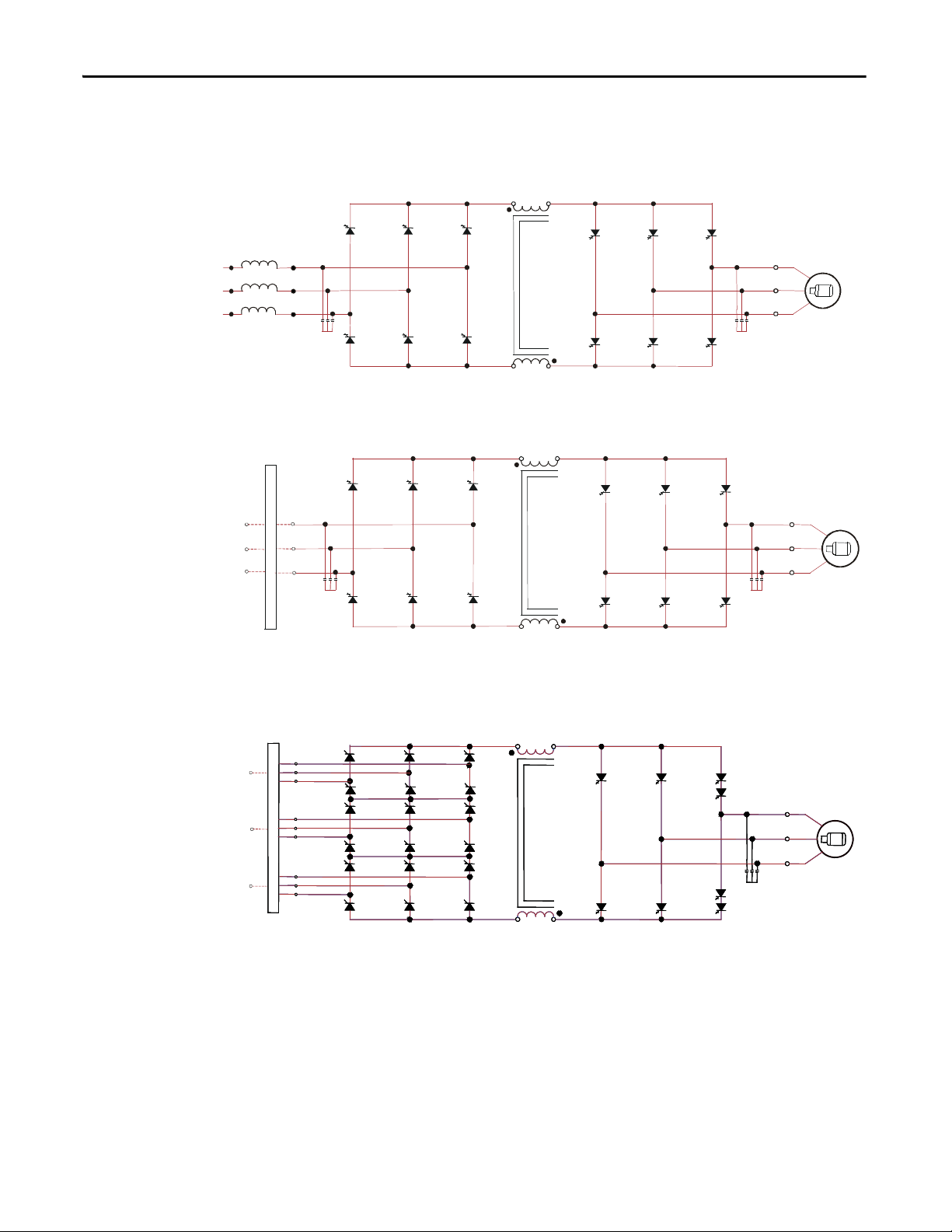
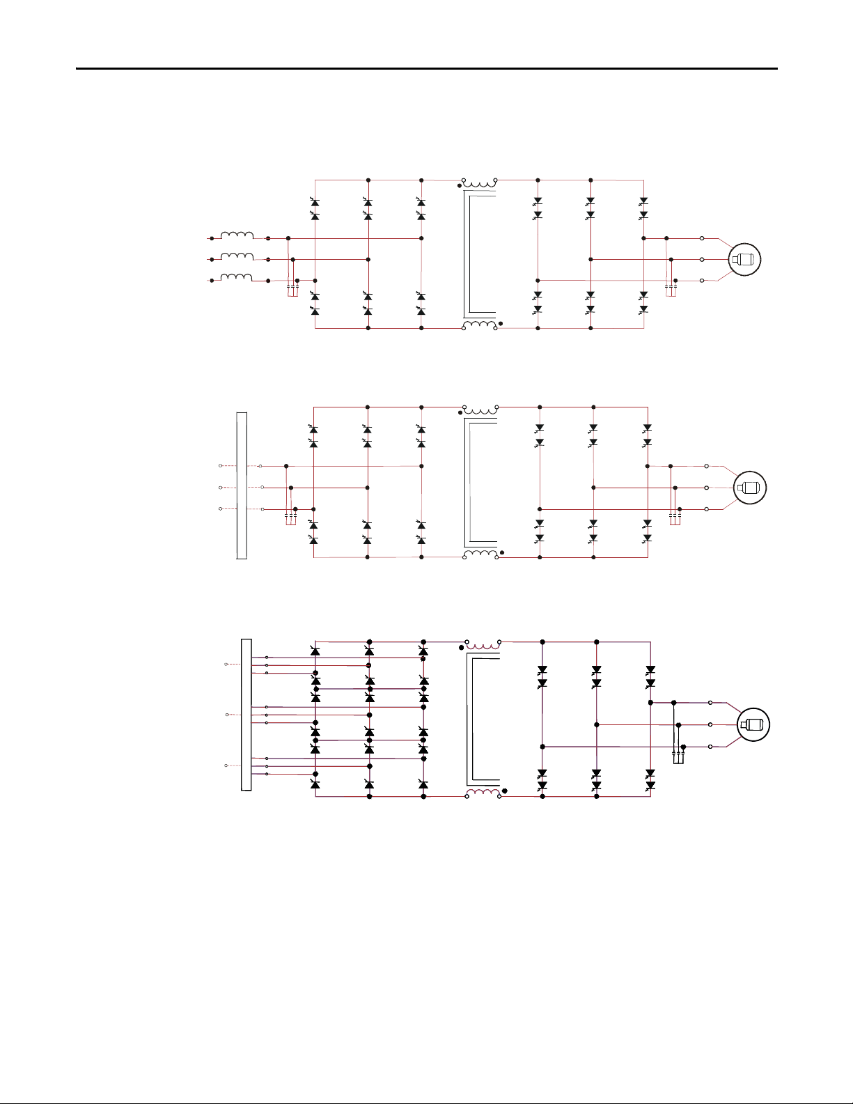
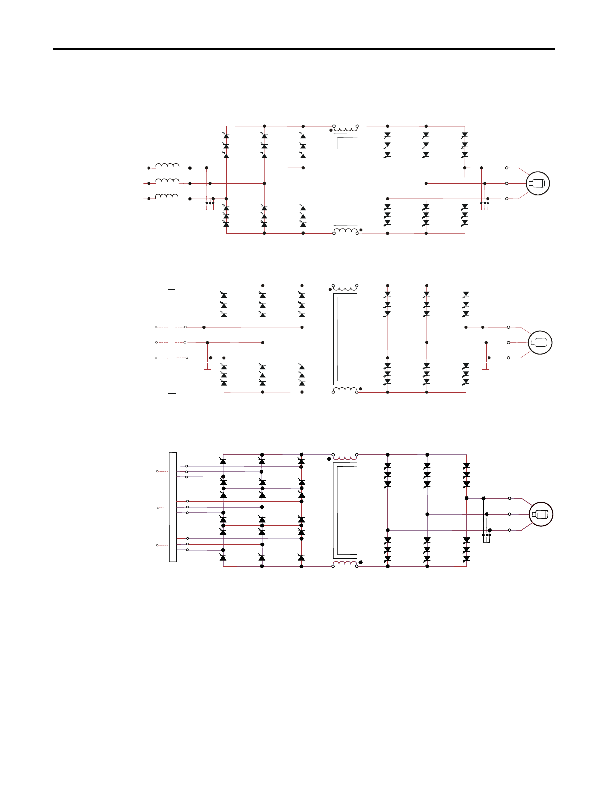
Simplified Electrical Diagrams . . . . . . . . . . . . . . . . . . . . . . . . . . . . . . . . . . . . 18
2400V. . . . . . . . . . . . . . . . . . . . . . . . . . . . . . . . . . . . . . . . . . . . . . . . . . . . . . . 18
3300/4160V . . . . . . . . . . . . . . . . . . . . . . . . . . . . . . . . . . . . . . . . . . . . . . . . . 19
6600V. . . . . . . . . . . . . . . . . . . . . . . . . . . . . . . . . . . . . . . . . . . . . . . . . . . . . . . 20
Operator Interface . . . . . . . . . . . . . . . . . . . . . . . . . . . . . . . . . . . . . . . . . . . . . . . 21
Basic Configurations . . . . . . . . . . . . . . . . . . . . . . . . . . . . . . . . . . . . . . . . . 21
Chapter 3
Control Power Off Tests . . . . . . . . . . . . . . . . . . . . . . . . . . . . . . . . . . . . . . . . . 23
Interlocking. . . . . . . . . . . . . . . . . . . . . . . . . . . . . . . . . . . . . . . . . . . . . . . . . . 23
Control / Cabling Cabinet Components. . . . . . . . . . . . . . . . . . . . . . . . . . . 25
Voltage-Sensing Assembly . . . . . . . . . . . . . . . . . . . . . . . . . . . . . . . . . . . . . . . . 33
Replacing the Voltage-Sensing Circuit Board Assembly. . . . . . . . . . 34
Input Transient Protection . . . . . . . . . . . . . . . . . . . . . . . . . . . . . . . . . . . . . . . 35
Transient Suppression Network (TSN) . . . . . . . . . . . . . . . . . . . . . . . . 35
Surge Arresters . . . . . . . . . . . . . . . . . . . . . . . . . . . . . . . . . . . . . . . . . . . . . . . 39
Filter Capacitor Cabinet. . . . . . . . . . . . . . . . . . . . . . . . . . . . . . . . . . . . . . . . . . 46
Filter Capacitors . . . . . . . . . . . . . . . . . . . . . . . . . . . . . . . . . . . . . . . . . . . . . 46
Replacing Filter Capacitors. . . . . . . . . . . . . . . . . . . . . . . . . . . . . . . . . . . . 47
Testing Filter Capacitors. . . . . . . . . . . . . . . . . . . . . . . . . . . . . . . . . . . . . . 48
Converter Cabinet Components . . . . . . . . . . . . . . . . . . . . . . . . . . . . . . . . . . 50
PowerCage™ Overview. . . . . . . . . . . . . . . . . . . . . . . . . . . . . . . . . . . . . . . . . . . . 55
Resistance Checks. . . . . . . . . . . . . . . . . . . . . . . . . . . . . . . . . . . . . . . . . . . . . . . . 56
SGCT and Snubber Circuit. . . . . . . . . . . . . . . . . . . . . . . . . . . . . . . . . . . . . . . 57
SGCT Testing . . . . . . . . . . . . . . . . . . . . . . . . . . . . . . . . . . . . . . . . . . . . . . . 63
SGCT Anode-to-Cathode (Sharing) Resistance. . . . . . . . . . . . . . . . . 64
Snubber Resistance (SGCT Device). . . . . . . . . . . . . . . . . . . . . . . . . . . . 66
Snubber Capacitance (SGCT Device). . . . . . . . . . . . . . . . . . . . . . . . . . 67
Replacing the SGCT. . . . . . . . . . . . . . . . . . . . . . . . . . . . . . . . . . . . . . . . . . 69
Replacing Snubber and Sharing Resistor. . . . . . . . . . . . . . . . . . . . . . . . 72
Replacing Snubber Capacitor. . . . . . . . . . . . . . . . . . . . . . . . . . . . . . . . . . 76
Replacing Sharing Resistors . . . . . . . . . . . . . . . . . . . . . . . . . . . . . . . . . . . 78
Rockwell Automation Publication 7000-UM202B-EN-P - June 2014 5
Page 6

Table of Contents
Silicon Controlled Rectifier PowerCages . . . . . . . . . . . . . . . . . . . . . . . . . . . 78
SCR Testing . . . . . . . . . . . . . . . . . . . . . . . . . . . . . . . . . . . . . . . . . . . . . . . . . 79
SCR Anode-to-Cathode Resistance . . . . . . . . . . . . . . . . . . . . . . . . . . . . 81
SCR Sharing Resistance Test . . . . . . . . . . . . . . . . . . . . . . . . . . . . . . . . . . 82
SCR Gate-to-Cathode Resistance . . . . . . . . . . . . . . . . . . . . . . . . . . . . . . 83
Snubber Resistance (SCR Device). . . . . . . . . . . . . . . . . . . . . . . . . . . . . . 84
Snubber Capacitance (SCR Device) . . . . . . . . . . . . . . . . . . . . . . . . . . . . 85
Replacing SCR and SCR Self-Powered Gate Driver
Boards (SPGDB) . . . . . . . . . . . . . . . . . . . . . . . . . . . . . . . . . . . . . . . . . . . . . 86
Uniform Clamping Pressure. . . . . . . . . . . . . . . . . . . . . . . . . . . . . . . . . . . . . . . 88
Checking Clamping Pressure . . . . . . . . . . . . . . . . . . . . . . . . . . . . . . . . . . 89
Clamping Pressure Adjustment . . . . . . . . . . . . . . . . . . . . . . . . . . . . . . . . 89
Temperature Sensing . . . . . . . . . . . . . . . . . . . . . . . . . . . . . . . . . . . . . . . . . . . . . 90
Replacing the Thermal Sensor . . . . . . . . . . . . . . . . . . . . . . . . . . . . . . . . . 90
Replacing Heat Sinks/Heat Pipes . . . . . . . . . . . . . . . . . . . . . . . . . . . . . . . . . . 93
Replacing Heat Sinks . . . . . . . . . . . . . . . . . . . . . . . . . . . . . . . . . . . . . . . . . 94
Replacing Heat Pipes. . . . . . . . . . . . . . . . . . . . . . . . . . . . . . . . . . . . . . . . . . 95
PowerCage Gasket . . . . . . . . . . . . . . . . . . . . . . . . . . . . . . . . . . . . . . . . . . . . . . . 97
Replacing PowerCage Gaskets . . . . . . . . . . . . . . . . . . . . . . . . . . . . . . . . . 98
Removing the PowerCage . . . . . . . . . . . . . . . . . . . . . . . . . . . . . . . . . . . . . 99
Self-Powered SGCT Power Supply - SPS . . . . . . . . . . . . . . . . . . . . . . . . . . 101
Board Calibration . . . . . . . . . . . . . . . . . . . . . . . . . . . . . . . . . . . . . . . . . . . 101
Test Points. . . . . . . . . . . . . . . . . . . . . . . . . . . . . . . . . . . . . . . . . . . . . . . . . . 101
Testing Equipment . . . . . . . . . . . . . . . . . . . . . . . . . . . . . . . . . . . . . . . . . . 103
Self-Powered Gate Driver Board – SPGDB . . . . . . . . . . . . . . . . . . . . . . . . 104
Board Calibration . . . . . . . . . . . . . . . . . . . . . . . . . . . . . . . . . . . . . . . . . . . 104
Test Points. . . . . . . . . . . . . . . . . . . . . . . . . . . . . . . . . . . . . . . . . . . . . . . . . . 104
Terminal/Connections . . . . . . . . . . . . . . . . . . . . . . . . . . . . . . . . . . . . . . 105
Testing Procedure for SCR Self-Powered Gate Driver Board . . . . . . . . 106
Testing Equipment . . . . . . . . . . . . . . . . . . . . . . . . . . . . . . . . . . . . . . . . . . 106
Procedure . . . . . . . . . . . . . . . . . . . . . . . . . . . . . . . . . . . . . . . . . . . . . . . . . . . 106
Fiber Optic Cabling . . . . . . . . . . . . . . . . . . . . . . . . . . . . . . . . . . . . . . . . . . . . . 109
Air Pressure Sensor . . . . . . . . . . . . . . . . . . . . . . . . . . . . . . . . . . . . . . . . . . . . . . 110
Replacing the Air Pressure Sensor . . . . . . . . . . . . . . . . . . . . . . . . . . . . . 111
DC Link and Fan Cabinet Components . . . . . . . . . . . . . . . . . . . . . . . . . . 111
DC Link Reactor . . . . . . . . . . . . . . . . . . . . . . . . . . . . . . . . . . . . . . . . . . . . 115
Removing and Replacing Fans . . . . . . . . . . . . . . . . . . . . . . . . . . . . . . . .
117
Fan Installation. . . . . . . . . . . . . . . . . . . . . . . . . . . . . . . . . . . . . . . . . . . . . . 119
Impeller Maintenance . . . . . . . . . . . . . . . . . . . . . . . . . . . . . . . . . . . . . . . . . . . 119
Impeller Removal from Motor Shaft. . . . . . . . . . . . . . . . . . . . . . . . . . . 119
Installing Impeller Assembly onto Motor Shaft. . . . . . . . . . . . . . . . . 120
Replacing Air Filters . . . . . . . . . . . . . . . . . . . . . . . . . . . . . . . . . . . . . . . . . 122
Control Power Components . . . . . . . . . . . . . . . . . . . . . . . . . . . . . . . . . . . . . 125
Ride-Through . . . . . . . . . . . . . . . . . . . . . . . . . . . . . . . . . . . . . . . . . . . . . . . 125
AC/DC Power Supply. . . . . . . . . . . . . . . . . . . . . . . . . . . . . . . . . . . . . . . . . . . 126
Terminal / Connections Descriptions (Pioneer Power Supply) . . 128
Terminal / Connections Descriptions (Cosel Power Supply) . . . . 129
6 Rockwell Automation Publication 7000-UM202B-EN-P - June 2014
Page 7

Table of Contents
Output Calibration. . . . . . . . . . . . . . . . . . . . . . . . . . . . . . . . . . . . . . . . . . 130
Power Supply Replacement. . . . . . . . . . . . . . . . . . . . . . . . . . . . . . . . . . . 131
UPS Option . . . . . . . . . . . . . . . . . . . . . . . . . . . . . . . . . . . . . . . . . . . . . . . . . . . . 133
Replacing the UPS. . . . . . . . . . . . . . . . . . . . . . . . . . . . . . . . . . . . . . . . . . . 135
Low Voltage Control Section . . . . . . . . . . . . . . . . . . . . . . . . . . . . . . . . . . . . 136
DC/DC Power Supply . . . . . . . . . . . . . . . . . . . . . . . . . . . . . . . . . . . . . . . . . . 137
Terminal/Connections Descriptions. . . . . . . . . . . . . . . . . . . . . . . . . . 138
Replacing a DC/DC Power Supply . . . . . . . . . . . . . . . . . . . . . . . . . . . 139
Drive Processor Module . . . . . . . . . . . . . . . . . . . . . . . . . . . . . . . . . . . . . . . . . 140
Replacing the Drive Processor Module . . . . . . . . . . . . . . . . . . . . . . . . 142
Analog Control Board (ACB). . . . . . . . . . . . . . . . . . . . . . . . . . . . . . . . . . . . 144
LEDs. . . . . . . . . . . . . . . . . . . . . . . . . . . . . . . . . . . . . . . . . . . . . . . . . . . . . . . 148
Interface Module (IFM) . . . . . . . . . . . . . . . . . . . . . . . . . . . . . . . . . . . . . 148
Analog Inputs and Outputs . . . . . . . . . . . . . . . . . . . . . . . . . . . . . . . . . . 149
Current Loop Transmitter. . . . . . . . . . . . . . . . . . . . . . . . . . . . . . . . . . . . . . . 149
Isolated Process Receiver . . . . . . . . . . . . . . . . . . . . . . . . . . . . . . . . . . . . . 150
Non-Isolated Process Outputs. . . . . . . . . . . . . . . . . . . . . . . . . . . . . . . . 151
Auxiliary +24V Power Supply . . . . . . . . . . . . . . . . . . . . . . . . . . . . . . . . 151
Replacing the ACB Analog Control Board . . . . . . . . . . . . . . . . . . . . 152
Encoder Feedback Board. . . . . . . . . . . . . . . . . . . . . . . . . . . . . . . . . . . . . . . . . 152
Encoder Options . . . . . . . . . . . . . . . . . . . . . . . . . . . . . . . . . . . . . . . . . . . . 152
20B-ENC-1 & 20B-ENC-1-MX3 Encoder Interface . . . . . . . . . . . 153
80190-759-01, 80190-759-02 Universal Encoder Interface . . . . . 154
Quadrature Encoder Operation . . . . . . . . . . . . . . . . . . . . . . . . . . . . . . 156
Positional Encoder Operations . . . . . . . . . . . . . . . . . . . . . . . . . . . . . . . 157
External Input/Output Boards . . . . . . . . . . . . . . . . . . . . . . . . . . . . . . . . . . . 159
Replacing the External Input/Output Board. . . . . . . . . . . . . . . . . . . 160
Optical Interface Boards (OIB) . . . . . . . . . . . . . . . . . . . . . . . . . . . . . . . . . . 161
Replacing the Optical Interface Board. . . . . . . . . . . . . . . . . . . . . . . . . 162
Optical Interface Base Board Test Points . . . . . . . . . . . . . . . . . . . . . . 165
Catalog Number Explanation
Preventative Maintenance Schedule
Rockwell Automation Publication 7000-UM202B-EN-P - June 2014 7
Appendix A
PowerFlex 7000 Drive Selection Explanation. . . . . . . . . . . . . . . . . . . . . . 168
Service Duty Rating, Continuous Current Rating and
Altitude Rating Code. . . . . . . . . . . . . . . . . . . . . . . . . . . . . . . . . . . . . . . . 168
Appendix B
Preventative Maintenance Checklist . . . . . . . . . . . . . . . . . . . . . . . . . . . . . . 169
Operational Maintenance. . . . . . . . . . . . . . . . . . . . . . . . . . . . . . . . . . . . . . . . 169
Annual Maintenance . . . . . . . . . . . . . . . . . . . . . . . . . . . . . . . . . . . . . . . . . . . . 169
Initial Information Gathering . . . . . . . . . . . . . . . . . . . . . . . . . . . . . . . . 170
Physical Checks (NO Medium Voltage and NO Control Power) 170
Control Power Checks (No Medium Voltage) . . . . . . . . . . . . . . . . . 171
Final Power Checks before Restarting . . . . . . . . . . . . . . . . . . . . . . . . . 172
Additional Tasks During Preventive Maintenance . . . . . . . . . . . . . 172
Final Reporting . . . . . . . . . . . . . . . . . . . . . . . . . . . . . . . . . . . . . . . . . . . . . 173
Page 8

Table of Contents
Torque Requirements
Time Estimations . . . . . . . . . . . . . . . . . . . . . . . . . . . . . . . . . . . . . . . . . . . 174
Tool / Parts / Information Requirements. . . . . . . . . . . . . . . . . . . . . . 174
Overview . . . . . . . . . . . . . . . . . . . . . . . . . . . . . . . . . . . . . . . . . . . . . . . . . . . . . . . 176
PowerFlex 7000 Preventative Maintenance Schedule . . . . . . . . . . . . . . . 177
Appendix C
Torque Requirements for Threaded Fasteners . . . . . . . . . . . . . . . . . . . . . 179
Appendix D
Meggering
Line & Load Cable Sizes
Environmental Considerations
Drive Meggering . . . . . . . . . . . . . . . . . . . . . . . . . . . . . . . . . . . . . . . . . . . . . . . . 181
Meggering the PowerFlex 7000 . . . . . . . . . . . . . . . . . . . . . . . . . . . . . . . 181
Meggering Procedures . . . . . . . . . . . . . . . . . . . . . . . . . . . . . . . . . . . . . . . . . . . 182
Required Equipment. . . . . . . . . . . . . . . . . . . . . . . . . . . . . . . . . . . . . . . . . 182
Procedure . . . . . . . . . . . . . . . . . . . . . . . . . . . . . . . . . . . . . . . . . . . . . . . . . . . 182
Appendix E
Max. Line Cable Sizes. . . . . . . . . . . . . . . . . . . . . . . . . . . . . . . . . . . . . . . . . . . . 187
Max. Load Cable Sizes . . . . . . . . . . . . . . . . . . . . . . . . . . . . . . . . . . . . . . . . . . . 190
Appendix F
Air Quality Requirements. . . . . . . . . . . . . . . . . . . . . . . . . . . . . . . . . . . . . . . . 193
Hazardous Materials. . . . . . . . . . . . . . . . . . . . . . . . . . . . . . . . . . . . . . . . . . . . . 194
Capacitor Dielectric Fluid . . . . . . . . . . . . . . . . . . . . . . . . . . . . . . . . . . . . 194
Printed Circuit Boards . . . . . . . . . . . . . . . . . . . . . . . . . . . . . . . . . . . . . . . 194
Lithium Batteries . . . . . . . . . . . . . . . . . . . . . . . . . . . . . . . . . . . . . . . . . . . . 194
Chromate Plating. . . . . . . . . . . . . . . . . . . . . . . . . . . . . . . . . . . . . . . . . . . . 195
In Case Of Fire . . . . . . . . . . . . . . . . . . . . . . . . . . . . . . . . . . . . . . . . . . . . . . 195
Disposal . . . . . . . . . . . . . . . . . . . . . . . . . . . . . . . . . . . . . . . . . . . . . . . . . . . . 195
Appendix G
Encoder Use and Torque Capabilities
When to use an Encoder? . . . . . . . . . . . . . . . . . . . . . . . . . . . . . . . . . . . . . . . . 197
PowerFlex 7000 Drive Performance (Torque Capabilities). . . . . . . . . . 198
Glossary of Terms . . . . . . . . . . . . . . . . . . . . . . . . . . . . . . . . . . . . . . . . . . . . . . . 199
Appendix H
Specifications
“B” Frame Drive Specifications . . . . . . . . . . . . . . . . . . . . . . . . . . . . . . . . . . . 201
Index
8 Rockwell Automation Publication 7000-UM202B-EN-P - June 2014
Page 9

Chapter 1
Important User Information
This document provides procedural information for managing daily or recurring
tasks involving the PowerFlex 7000 medium voltage “B” Frame drives (heat sink
and heat pipe models).
Who Should Use This Manual
What Is Not in this Manual
This manual is intended for use by personnel familiar with medium voltage and
solid-state variable speed drive equipment. The manual contains material that
enables regular operation and maintenance of the drive system.
This manual provides information specific to maintaining the PowerFlex 7000
“B” Frame drive. It does not include topics such as:
• Physically transporting or siting the drive cabinetry
• Installing or commissioning procedures
• Dimensional and electrical drawings generated for each customer’s order
• Spare parts lists compiled for each customer’s order
Please refer to the following documents for additional product detail or
instruction relating to PowerFlex 7000 “B” Frame drives:
• Drive-specific Technical Data: additional troubleshooting, parameters,
and specification information for MV variable frequency drives
(7000-TD002_-EN-P
• Transportation and Handling Procedures: receiving and handling
instructions for Medium Voltage variable frequency drive and related
equipment (7000-IN008_-EN-P
• Installation Guide: detailed installation and pre-commissioning
procedures and information (7000-IN007_-EN-P
• Commissioning Guide: required procedures and checklists for Rockwell
Automation field service engineers (7000-IN006_-EN-P
• Operator Interface Guide: HMI Offering with Enhanced Functionality
(7000-UM201_-EN-P
• For drives equipped with the PanelView 550 HMI,
see 7000-UM151_-EN-P.
)
)
)
)
)
Rockwell Automation provides the site- and installation-specific electrical and
design information for each drive during the order process cycle. If they are not
available on site with the drive, contact Rockwell Automation.
Rockwell Automation Publication 7000-UM202B-EN-P - June 2014 9
Page 10
Chapter 1 Important User Information
If you have multiple drive types or power ranges, ensure you have the correct
documentation for each specific PowerFlex 7000 product:
• “A” Frame for lower power air-cooled configurations (up to approximately
1250 hp/933 kW)
• “B” Frame for higher-power, air-cooled configurations (standard or heat
pipe models)
• “C” Frame for all liquid-cooled configurations
General Precautions
Commissioning Support
ATT EN TI ON : This drive contains ESD (Electrostatic Discharge) sensitive parts
and assemblies. Static control precautions are required when installing, testing,
servicing or repairing this assembly. Component damage may result if ESD
control procedures are not followed. If you are not familiar with static control
procedures, reference Allen-Bradley publication 8000-4.5.2, “Guarding Against
Electrostatic Damage” or any other applicable ESD protection handbook.
ATT EN TI ON : An incorrectly applied or installed drive can result in component
damage or a reduction in product life. Wiring or application errors, such as,
undersizing the motor, incorrect or inadequate AC supply, or excessive ambient
temperatures may result in malfunction of the system.
ATT EN TI ON : Only personnel familiar with the PowerFlex 7000 Adjustable
Speed Drive (ASD) and associated machinery should plan or implement the
installation, start-up and subsequent maintenance of the system. Failure to
comply may result in personal injury and/or equipment damage.
After installation, Rockwell Automation Medium Voltage Support is responsible
for commissioning support and activities in the PowerFlex 7000 product line.
Phone: 519-740-4790
Option 1 for technical and option 4 for commissioning questions
MVSupport_technical@ra.rockwell.com or
MVSupport_services@ra.rockwell.com
Rockwell Automation support includes, but is not limited to:
• quoting and managing product on-site start-ups
• quoting and managing field modification projects
• quoting and managing customer in-house and on-site product training
10 Rockwell Automation Publication 7000-UM202B-EN-P - June 2014
Page 11
Important User Information Chapter 1
Additional Resources
These documents contain additional information concerning related products
from Rockwell Automation.
Resource Description
Publication 7000-PP002_-EN-P
Publication 7000A-UM150_-EN-P PowerFlex 7000 Medium Voltage AC Drive (A Frame) - Classic Control
Publication 7000A-UM151_-EN-P
Publication 7000-UM150_-EN-P PowerFlex 7000 Medium Voltage AC Drive (B Frame) - Classic Control
Publication 7000-UM151_-EN-P PowerFlex 7000 Medium Voltage AC Drive (B Frame) - ForGe Control
Publication 7000-UM202_-EN-P PowerFlex 7000 Medium Voltage AC Drive (B Frame) - ForGe Control
Publication 7000-IN006_-EN-P PowerFlex 7000 Medium Voltage AC Drive (B Frame) Commissioning -
Publication 7000-IN007_-EN-P PowerFlex 7000 Medium Voltage AC Drive (B Frame) Installation -
Publication 7000-IN008_-EN-P
Publication 7000L-UM301_-EN-P
Publication 7000L-UM302_-EN-P
Publication 7000-TD001_-EN-P
Publication 7000-TD002_-EN-P PowerFlex 7000 Medium Voltage AC Drive (Firmware Version 9.xxx) -
Publication 7000-UM201_-EN-P
Publication 7000-QS002_-EN-P
Publication 7000-IN010B-EN-P Handling, Inspection, and Storage of Medium Voltage Line Filter
PowerFlex 7000 Air-Cooled Drives
PowerFlex 7000 Medium Voltage AC Drive (A Frame) - ForGe Control
(Using PanelView 550)
(Using PanelView 500)
ForGe Co ntrol
ForGe Co ntrol
PowerFlex 7000 Medium Voltage AC Drive (B Frame) Trans. & Handling
- ForGe Control
PowerFlex 7000 Medium Voltage AC Drive (C Frame) - ForGe Control
PowerFlex 7000 Medium Voltage AC Drive (C Frame) - ForGe Control
(Marine)
PowerFlex 7000 Medium Voltage AC Drive (Firmware Version 6.xxx) -
Classic Control
ForGe Co ntrol
PowerFlex 7000 HMI Offering with Enhanced Functionality
HMI Interface Board Software Updater and Firmware Download
Procedure
Capacitors
You can view or download publications at
http:/www.rockwellautomation.com/literature/
. To order paper copies of
technical documentation, contact your local Allen-Bradley distributor or
Rockwell Automation sales representative.
Rockwell Automation Publication 7000-UM202B-EN-P - June 2014 11
Page 12

Chapter 1 Important User Information
Notes:
12 Rockwell Automation Publication 7000-UM202B-EN-P - June 2014
Page 13

Chapter 2
PowerFlex 7000 Overview
The PowerFlex 7000 is a general purpose, stand-alone, medium voltage drive that
controls speed, torque, direction, starting and stopping of standard asynchronous
or synchronous AC motors. It works on numerous standard and specialty
applications such as fans, pumps, compressors, mixers, conveyors, kilns, fanpumps, and test stands in industries such as petrochemical, cement, mining and
metals, forest products, power generation, and water/waste water.
The PowerFlex 7000 meets most common standards from the National Electrical
Code (NEC), International Electrotechnical Commission (IEC), National
Electrical Manufacturers Association (NEMA), Underwriters Laboratories
(UL), and Canadian Standards Association (CSA). It is available with the world’s
most common supply voltages at medium voltage, from 2400...6600V.
Topology
The design focus is on high reliability, ease of use, and lower total cost of
ownership.
The PowerFlex 7000 uses a Pulse Width Modulated (PWM) – Current Source
Inverter (CSI) topology. This topology applies to a wide voltage and power
range. The power semiconductor switches used are easy-to-series for any medium
voltage level. Semiconductor fuses are not required for the power structure due to
the current limiting DC link inductor.
With 6500V PIV rated power semiconductor devices, the number of inverter
components is minimal. For example, only six inverter switching devices are
required at 2400V, 12 at 3300...4160V, and 18 at 6600V.
The PowerFlex 7000 also provides inherent regenerative braking for applications
where the load is overhauling the motor (e.g. downhill conveyors, etc.), or where
high inertia loads (e.g. fans, etc.) are quickly slowed down. The drive uses
Symmetrical Gate Commutated Thyristors (SGCTs) for machine converter
switches, SGCTs (for Active Front-end [AFE] rectifier configurations) for the
line converter switches and Silicon-controlled Rectifiers (SCRs) (for 18 Pulse
rectifier configurations).
The PowerFlex 7000 provides a selectable option for enhanced torque control
capabilities and increased dynamic control performance. This High Performance
Torque Control (HPTC) feature delivers 100% torque at zero speed and
provides torque control through zero speed with smooth direction transition.
Rockwell Automation Publication 7000-UM202B-EN-P - June 2014 13
Page 14
Chapter 2 PowerFlex 7000 Overview
Rectifier Designs
Configurations
The PowerFlex 7000 offers three rectifier configurations for "B" Frame drives:
• Direct-to-Drive (AFE rectifier with integral line reactor and Common
Mode Choke)
• AFE rectifier with separate isolation transformer
• 18 Pulse rectifier with separate isolation transformer
Direct-to-Drive
Direct-to-DriveTM technology does not require an isolation transformer or
multiple rectifier bridges as in Voltage Source Inverter (VSI) topologies offered
by others. The approach is completely different. Instead of multiple
uncontrolled rectifiers, a single AFE rectifier bridge is supplied. The rectifier
semiconductors used are SGCTs. Unlike the diodes used in VSI rectifier bridges,
SGCTs are turned on and off by a gating signal. A PWM gating algorithm
controls the firing of the rectifier devices, very similar to the control philosophy
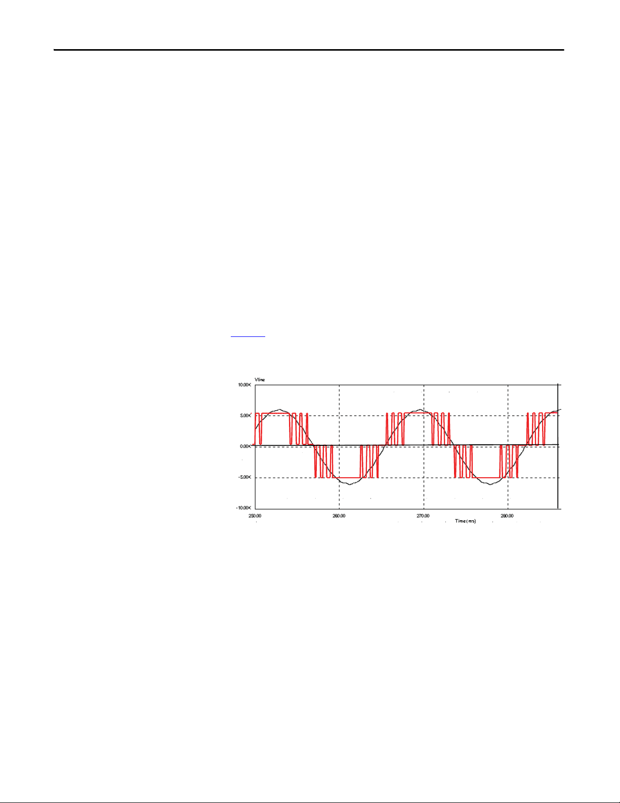
of the inverter. The gating algorithm uses a specific 42 pulse switching pattern
(Figure 1
and 11th harmonic orders.
Figure 1 - Typical PWM switching pattern, line voltage waveform
) called Selective Harmonic Elimination (SHE) to mitigate the 5th, 7th,
A small integral line reactor and capacitor addresses the high harmonic orders
(13th and above) and provides virtually sinusoidal input voltage and current
waveforms back to the distribution system. This delivers excellent line-side
harmonic and power factor performance to meet IEEE 519-1992 requirements
and other global harmonic standards in virtually all cases, while still providing a
simple, robust power structure that maximizes uptime by minimizing the number
of discrete components and the number of interconnections required.
A Common Mode Choke (CMC) mitigates the common mode voltage seen at
the motor terminals, so standard (non-inverter duty rated) motors and motor
cables can be used, making this technology ideal for retrofitting existing motor
applications.
14 Rockwell Automation Publication 7000-UM202B-EN-P - June 2014
Page 15
PowerFlex 7000 Overview Chapter 2
SGCTs
LINE CONVERTER
OMMON MODE CHOKE
C
L+
M+
SGCTs
MACHINE CONVERTER
U(T1)
V(T2)
W(T3)
L-
M-
LR
SGCTs
LINE CONVERTER DC LINK
L+
M+
SGCTs
MACHINE CONVERTER
U(T1)
V (T2)
W(T3)
L-
M-
2U (X1)
2V (X2)
2W (X3)
1U
1V
1W
ISTXISTX
REMOTE
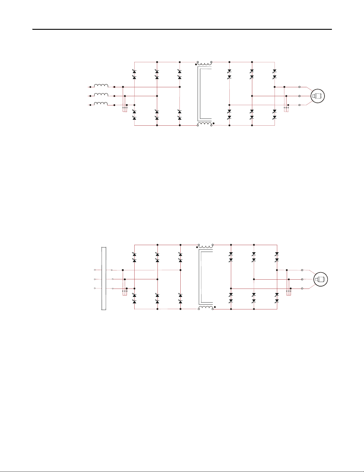
Figure 2 - 3300/4160V Direct-to-Drive (transformerless AFE rectifier)
AFE Rectifier with Separate Isolation Transformer
For applications when the line voltage is higher than the motor voltage, a
transformer is required for voltage matching. In this case, providing an AFE
rectifier with a separate isolation transformer is ideal (indoor and outdoor
transformer versions are offered). The isolation transformer provides the input
impedance (replaces the requirement for an integral line reactor) and addresses
the common mode voltage (replaces the requirement for a CMC that is supplied
in the Direct-to-Drive rectifier configuration). However, the AFE rectifier, its
operation, and advantages are the same as the Direct-to-Drive configuration.
Figure 3 - 3300/4160 AFE Rectifier with separate isolation transformer
Rockwell Automation Publication 7000-UM202B-EN-P - June 2014 15
Page 16
Chapter 2 PowerFlex 7000 Overview
LINE CONVERTER
L- M-
L+ M+
MACHINE CONVERTER
U (T1)
V (T2)
W (T3)
4U (Z1)
4V (Z2)
4W (Z3)
ISTX
SCRs
3U (Y1)
3V (Y2)
3W (Y3)
2U (X1)
2V (X2)
2W (X3)
SGCTs
LINE CONVERTER
L- M-
L+ M+
MACHINE CONVERTER
U (T1)
V (T2)
W (T3)
4U (Z1)
4V (Z2)
4W (Z3)
ISTX
SCRs
3U (Y1)
3V (Y2)
3W (Y3)
2U (X1)
2V (X2)
2W (X3)
SGCTs
REMOTE
1U
1V
1W
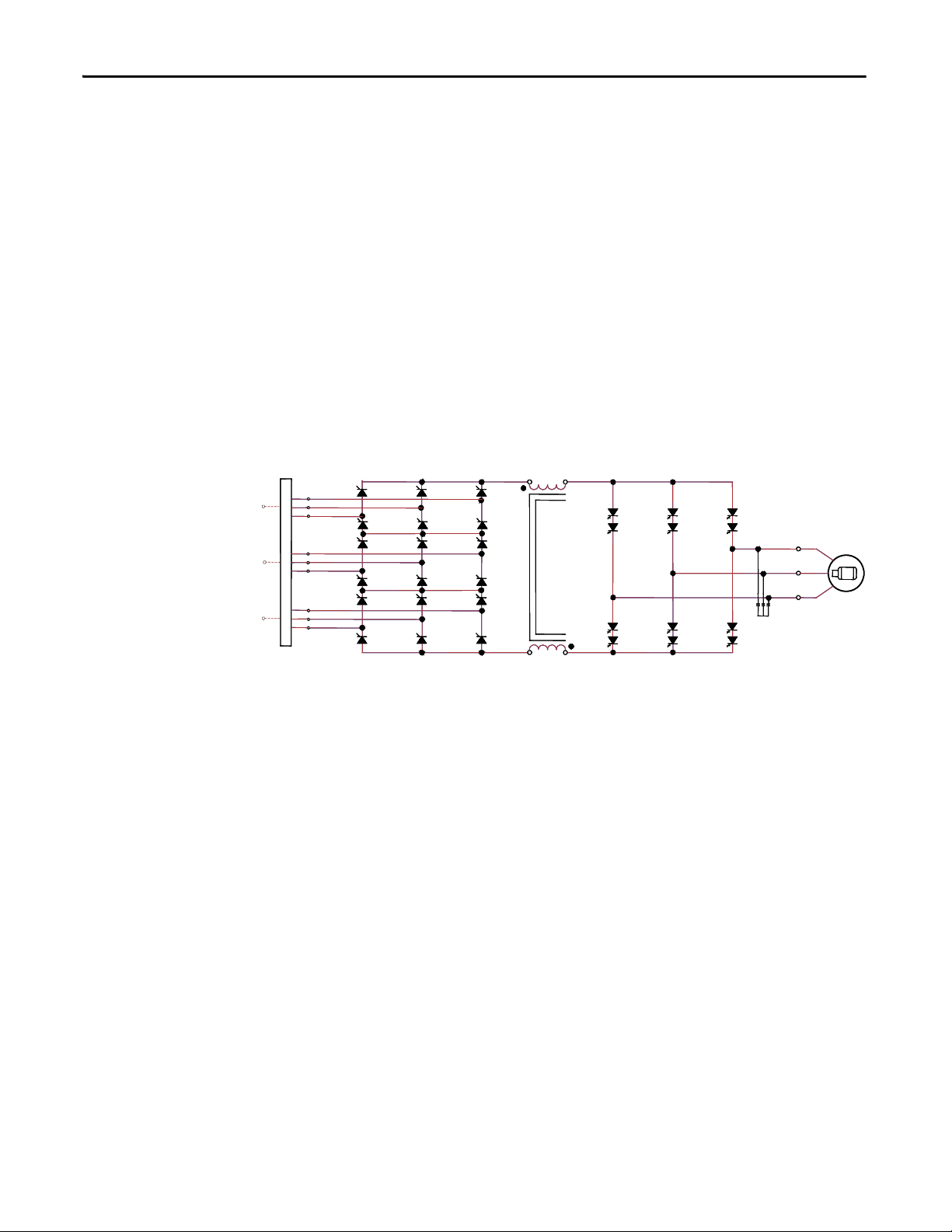
18 Pulse Rectifier with Separate Isolation Transformer
For high power constant torque applications and/or when the line voltage is
higher than the motor voltage, a transformer is required for voltage matching
(indoor and outdoor transformer options are available). The 18 Pulse rectifier
uses SCRs instead of the SGCTs used for an AFE rectifier. When used for high
power constant torque applications, the 18 Pulse rectifier has lower losses than
the AFE rectifier, making it ideal for the highest power requirements. The 18
Pulse isolation transformer provides the required input impedance and addresses
common mode voltage just like the separate isolation transformer used with the
AFE rectifier. However, instead of a PWM rectifier switching pattern and a
single rectifier bridge, the 18 Pulse configuration mitigates line side harmonics
through harmonic current cancellation in the isolation transformer phase shifted
secondary windings. The inverter is the same configuration for all available
rectifier options.
Figure 4 - 3300/4160V 18 Pulse rectifier with Separate Isolation Transformer
DC LINK
DC LINK
Cooling Technology
These VFDs are supplied with heat sinks for most configurations and heat pipes
for the highest-power AFE configurations. While both configurations draw heat
away from the semiconductors, heat pipes are bigger, more efficient, and require
larger fans and airflow.
Information and graphics in this manual show both configurations.
16 Rockwell Automation Publication 7000-UM202B-EN-P - June 2014
Page 17
PowerFlex 7000 Overview Chapter 2
300.00
200.00
100.00
0.00
-100.00
-200.00
-300.00
10.00K
7.50K
5.00K
2.50K
0.00K
-2.50K
-5.00K
-7.50K
-10.00K
100.00
110.00
120.00 130.00
140.00
150.00
Vrms
CURRENT
VOLTAGE
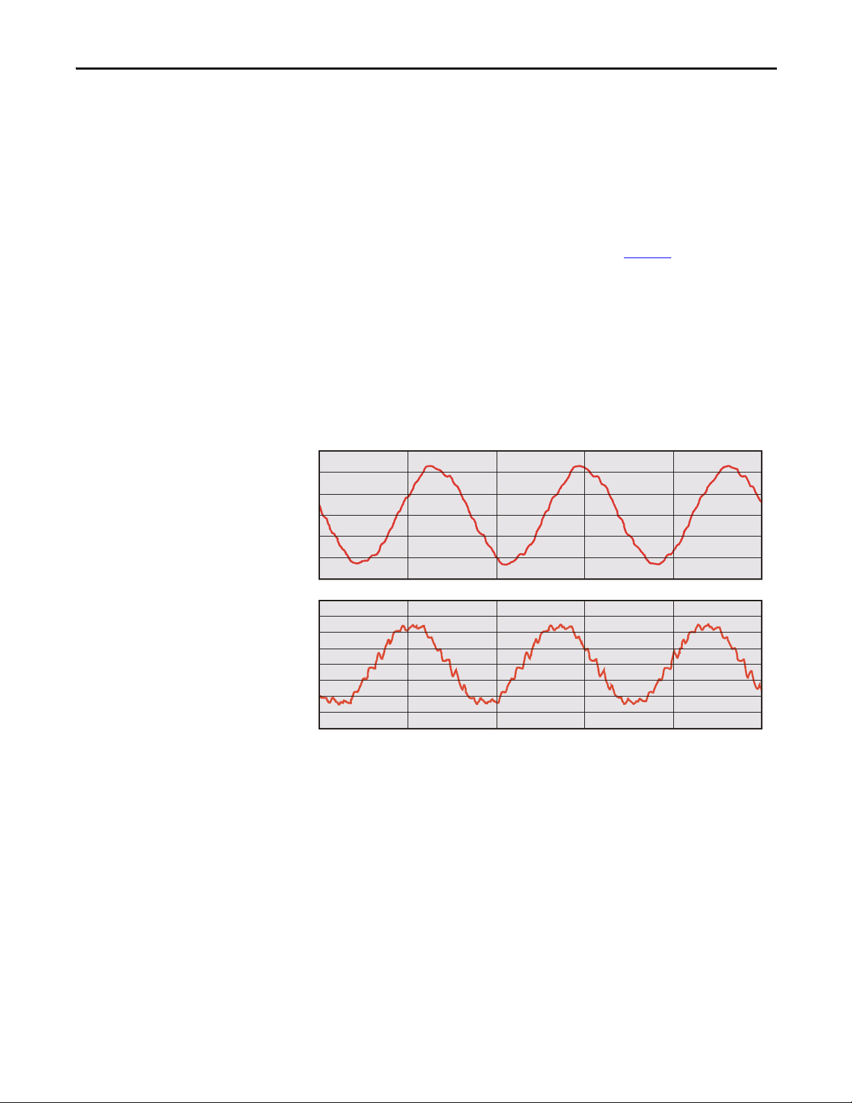
Motor Compatibility
The PowerFlex 7000 achieves near-sinusoidal current and voltage waveforms to
the motor, resulting in no significant additional heating or insulation stress.
Temperature rise in the motor connected to the VFD is typically 3 °C (5.5 °F)
higher compared to across-the-line operation. Voltage waveform has dv/dt of less
than 50 V/
µs. The peak voltage across the motor insulation is the rated motor
RMS voltage divided by 0.707.
Reflected wave and dv/dt issues often associated with voltage source inverter
(VSI) drives are a non-issue with the PowerFlex 7000. Figure 5
shows typical
motor waveforms. The drive uses a selective harmonic elimination (SHE) pattern
in the inverter to eliminate major order harmonics, plus a small output capacitor
(integral to the drive) to eliminate harmonics at higher speeds.
Standard motors are compatible without de-rating, even on retrofit applications.
Motor cable distance is virtually unlimited. Rockwell Automation has tested this
technology for controlling motors up to 15 km (9.3 mi) away from the drive.
Figure 5 - Motor waveforms @ full load, full speed
Arms
TIME (ms)
Rockwell Automation Publication 7000-UM202B-EN-P - June 2014 17
Page 18
Chapter 2 PowerFlex 7000 Overview
SGCTs
LINE CONVERTER
L+
M+
SGCTs
MACHINE CONVERTER
U(T1)
V(T2)
W(T3)
L-
M-
LR
OMMON MODE CHOKE
C
SGCTs
LINE CONVERTER DC LINK
L+
M+
SGCTs
MACHINE CONVERTER
U (T1)
V (T2)
W (T3)
L-
M-
2U (X1)
2V (X2)
2W (X3)
1U
1V
1W
ISTXISTX
REMOTE
LINE CONVERTER
L- M-
L+ M+
MACHINE CONVERTER
U (T1)
V (T2)
W (T3)
4U (Z1)
4V (Z2)
4W (Z3)
ISTX
SCRs
3U (Y1)
3V (Y2)
3W (Y3)
2U (X1)
2V (X2)
2W (X3)
SGCTs
LINE CONVERTER
L- M-
L+ M+
MACHINE CONVERTER
U (T1)
V (T2)
W (T3)
4U (Z1)
4V (Z2)
4W (Z3)
ISTX
SCRs
3U (Y1)
3V (Y2)
3W (Y3)
2U (X1)
2V (X2)
2W (X3)
SGCTs
1U
1V
1W
REMOTE
Simplified Electrical Diagrams
2400V
Figure 6 - 2400V – Direct-to-Drive (transformerless AFE rectifier)
Figure 7 - 2400V – AFE Rectifier with Separate Isolation Transformer
Figure 8 - 2400V – 18 Pulse Rectifier with Separate Isolation Transformer
DC LINK
DC LINK
18 Rockwell Automation Publication 7000-UM202B-EN-P - June 2014
Page 19
PowerFlex 7000 Overview Chapter 2
SGCTs
LINE CONVERTER
L+
M+
SGCTs
MACHINE CONVERTER
U(T1)
V(T2)
W(T3)
L-
M-
LR
OMMON MODE CHOKE
C
SGCTs
LINE CONVERTER DC LINK
L+
M+
SGCTs
MACHINE CONVERTER
U(T1)
V (T2)
W(T3)
L-
M-
2U (X1)
2V (X2)
2W (X3)
1U
1V
1W
ISTXISTX
REMOTE
LINE CONVERTER
L- M-
L+ M+
MACHINE CONVERTER
U (T1)
V (T2)
W (T3)
4U (Z1)
4V (Z2)
4W (Z3)
ISTX
SCRs
3U (Y1)
3V (Y2)
3W (Y3)
2U (X1)
2V (X2)
2W (X3)
SGCTs
LINE CONVERTER
L- M-
L+ M+
MACHINE CONVERTER
U (T1)
V (T2)
W (T3)
4U (Z1)
4V (Z2)
4W (Z3)
ISTX
SCRs
3U (Y1)
3V (Y2)
3W (Y3)
2U (X1)
2V (X2)
2W (X3)
SGCTs
REMOTE
1U
1V
1W
3300/4160V
Figure 9 - 3300/4160V – Direct-to-Drive (transformerless AFE rectifier)
Figure 10 - 3300/4160V – AFE Rectifier with Separate Isolation Transformer
Figure 11 - 3300/4160V – 18 Pulse Rectifier with Separate Isolation Transformer
DC LINK
DC LINK
Rockwell Automation Publication 7000-UM202B-EN-P - June 2014 19
Page 20
Chapter 2 PowerFlex 7000 Overview
SGCTs
L+
M+
SGCTs
U(T1)
V(T2)
W(T3)
L-
M-
LR
OMMON MODE CHOKE
C
SGCTs
LINE CONVERTER DC LINK
L+
M+
SGCTs
MACHINE CONVERTER
U (T1)
V (T2)
W (T3)
L-
M-
2U (X1)
2V (X2)
2W (X3)
1U
1V
1W
ISTXISTX
REMOTE
LINE CONVERTER
L- M-
L+ M+
MACHINE CONVERTER
U (T1)
V (T2)
W (T3)
4U (Z1)
4V (Z2)
4W (Z3)
ISTX
SCRs
3U (Y1)
3V (Y2)
3W (Y3)
2U (X1)
2V (X2)
2W (X3)
SGCTs
LINE CONVERTER
L- M-
L+ M+
MACHINE CONVERTER
U (T1)
V (T2)
W (T3)
4U (Z1)
4V (Z2)
4W (Z3)
ISTX
SCRs
3U (Y1)
3V (Y2)
3W (Y3)
2U (X1)
2V (X2)
2W (X3)
SGCTs
1U
1V
1W
REMOTE
6600V
Figure 12 - 6600V – Direct-to-Drive (transformerless AFE rectifier)
LINE CONVERTER
Figure 13 - 6600V – AFE Rectifier with Separate Isolation Transformer
MACHINE CONVERTER
Figure 14 - 6600V - 18 Pulse Rectifier with Separate Isolation Transformer
DC LINK
DC LINK
20 Rockwell Automation Publication 7000-UM202B-EN-P - June 2014
Page 21

PowerFlex 7000 Overview Chapter 2
Operator Interface
The HMI Interface Board is an HMI-enabling device for the PowerFlex 7000
drive. It allows the user to acquire all the necessary executable tools,
documentation and reports required to commission, troubleshoot and maintain
the drive.
Via the HMI Interface Board, the user can choose the style and size of the desired
Windows-based operator terminal to interact with the drive (e.g. PanelView CE
terminal, laptop, or desktop computer). The HMI Interface Board removes past
issues with compatibility between the drive and configuration tools, as all the
necessary tools are acquired from the drive.
The HMI Interface Board is well suited for applications that require remote
placement of the operator terminal and remote maintenance.
Figure 15 - Operator Interface
Basic Configurations
There are three basic configurations for the HMI.
Remote-mounted HMI
The HMI is not mounted in the traditional location on the low voltage door of
the Variable Frequency Drive (VFD). A remote mounting plate, complete with
E-Stop push button, and HMI is supplied loose for the customer to mount
wherever desired. The HMI connects to the VFD via a hardwired Ethernet cable.
There is no significant functional distance limitation.
Rockwell Automation Publication 7000-UM202B-EN-P - June 2014 21
Page 22

Chapter 2 PowerFlex 7000 Overview
This is ideal for non-PLC users wanting to control and monitor remotely (e.g. at
the driven machine, control room, etc.). Also ideal for customers having policies
in place to control access to medium voltage equipment and the associated
requirements of PPE when using the operator interface at the VFD, etc.
Locally-mounted HMI
Similar to the previously offered PanelView 550, the HMI is mounted on the LV
door of the VFD. There is also a service access port (RJ-45 connector) on the LV
door.
No HMI supplied
A service access port (RJ-45 connector) is located on the LV door of the VFD.
Customers use their own laptop as the HMI. All programs required to use the
laptop as the HMI are stored in the VFD. Their laptop is connected to the VFD
via a hardwired Ethernet cable, when required. This is ideal for unmanned sites,
where a dedicated HMI is not required.
See Publication 7000-UM201_-EN-P
HMI.
See Publication 7000-UM151_-EN-P
drives using the PanelView 550 HMI.
for detailed instruction for the
for detailed instruction for “B” Frame
22 Rockwell Automation Publication 7000-UM202B-EN-P - June 2014
Page 23

Chapter 3
IMPORTANT
Component Definition and Maintenance
This section provides an overview of the control components and cabling of your
PowerFlex 7000 “B” Frame drive. It also details a number of regular or recurring
maintenance tasks that will keep your drive in peak operating condition.
The following illustrations identify the control components and cabling of your
drives. Where appropriate, separate diagrams and instructions are available for
both the heat sink and the heat pipe “B” Frame models.
For information regarding power wiring and cabling connections (as might be
necessary for routine maintenance) refer to the PowerFlex 7000 “B” Frame
Installation Manual (7000-IN007_-EN-P
).
Control Power Off Tests
Perform the following checks before applying control power to the drive.
Rockwell Automation recommends that you complete these checks in the
sequence they are presented here.
This section is also available in the PowerFlex “B” Frame Commissioning Guide
(7000-IN006_-EN-P
drive testing.
); refer to that document for additional information on
Interlocking
When the input contactor option is purchased, a key interlock is provided to
prevent access to the medium voltage compartments of the drive unless the input
isolation switch is locked in the open position.
Where the input switching device is provided by others, Rockwell Automation
will provide a key interlock on the medium voltage compartment of the drive,
and a matching interlock for installation by others on the upstream device. The
interlock shall be installed in a manner that ensures the power to the drive is off
and the drive is electrically isolated whenever the key is freed.
Although Key interlocks shipped with all medium voltage equipment are aligned
in the factory, they often move out of position during shipping or are often
misaligned when the cabinet is set down on an uneven floor. The following
instructions will assist the field engineers in quickly and accurately aligning the
deadbolt key interlock with its counterpart.
Rockwell Automation Publication 7000-UM202B-EN-P - June 2014 23
Page 24
Chapter 3 Component Definition and Maintenance
ATT EN TI ON : Servicing energized industrial control equipment can be
hazardous. Severe injury or death can result from electrical shock, burn, or
unintended actuation of control equipment. Hazardous voltages may exist in
the cabinet even with the circuit breaker in the off position. Recommended
practice is to disconnect or lock out control equipment from power sources, and
confirm discharge of stored energy in capacitors. If it is necessary to work in the
vicinity of energized equipment, the safety related work practices of NFPA 70E,
Electrical Safety requirements for Employee Work places, must be followed.
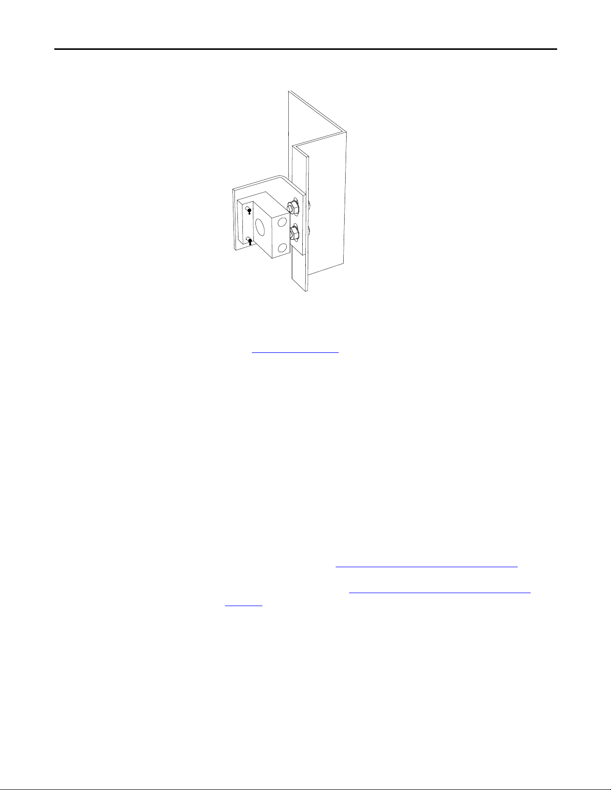
Figure 16 - Deadbolt assembly mounted to door
1. Lock out and isolate the drive from medium voltage. Verify with a hot
stick that there is no medium voltage present.
2. Determine that the key interlock is correctly aligned by securely bolting
the medium voltage doors of the cabinet closed and removing the key from
the lock. The key should turn easily; if any force is required to turn the key,
the deadbolt alignment requires adjustment.
3. Open the doors of the cabinet and inspect the key assembly. Place high
visibility grease on the pins of the deadbolt counterpart. The factory
recommends using yellow torque sealant, however if it is unavailable
almost any grease will do (Figure 17
).
24 Rockwell Automation Publication 7000-UM202B-EN-P - June 2014
Page 25
Component Definition and Maintenance Chapter 3
Figure 17 - Deadbolt counterpart mounted to cabinet
4. Bolt the cabinet door closed so the pins on the dead bolt counterpart make
contact with the deadbolt assembly. Doing so should leave two marks of
torque sealant or grease on the assembly where the pins made contact (see
Figure 16 on page 24
).
Control / Cabling Cabinet Components
5. Slightly loosen the adjustment bolts on the counterpart and make the
necessary movements on the counterpart to ensure that the pins align with
the landing plates on the deadbolt assembly. As the amount of counterpart
movement required is an estimate, it may take a couple attempts to
properly align the assembly.
6. Clean the torque seal/grease from the key interlock once finished aligning
the counterpart.
Once properly aligned, the key should turn freely when the cabinet door is fully
bolted shut. If the key does not function when the door is tightly bolted closed,
adjustments will have to be made to the depth of the counterpart. This can be
done by adding shims on the landing plate where the counterpart is mounted.
For converter cabinets, see Converter Cabinet Components on page 50.
For DC link/fan cabinets, see DC Link and Fan Cabinet Components
page 111.
on
Rockwell Automation Publication 7000-UM202B-EN-P - June 2014 25
Page 26
Chapter 3 Component Definition and Maintenance
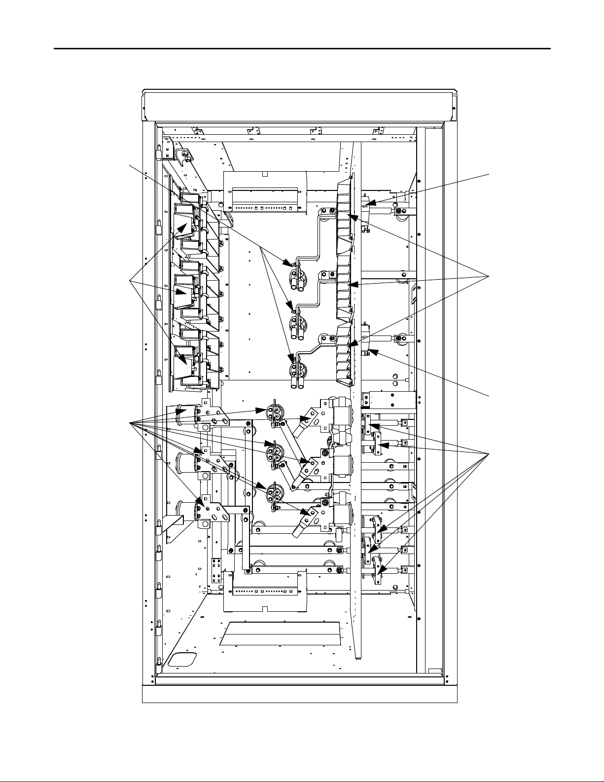
Grounding Network (For use
with Isolation Transformer)
or
Ground Filter (For use with
Line Reactor)
Motor Filter Capacitors
Hall Effect Sensors
Sensing Boards
Line Terminals
Motor Terminals
Current Transformers
Surge Arresters
Figure 18 - Cabling cabinet for AFE rectifier (heat sink model)
26 Rockwell Automation Publication 7000-UM202B-EN-P - June 2014
Page 27
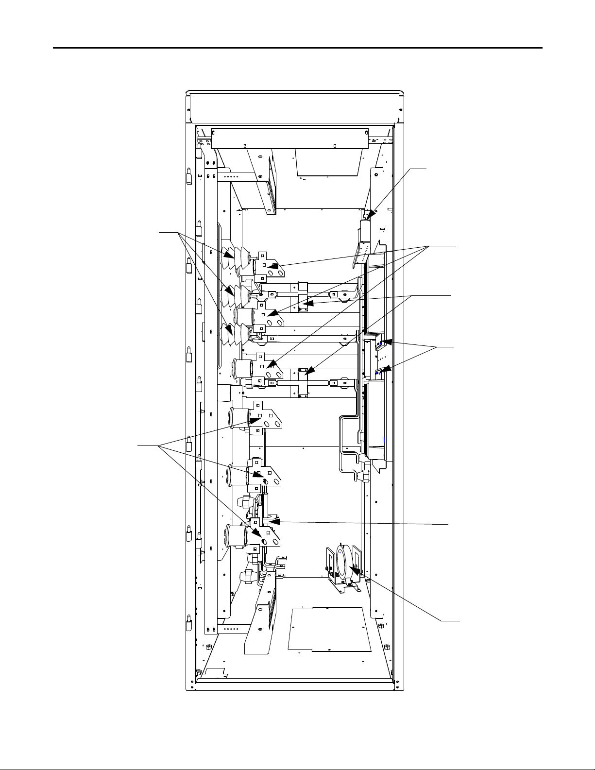
Grounding Network (For use
with Isolation Transformer)
or
Ground Filter (For use with
Line Reactor)
Surge Arresters
Voltage Sensing Boards
Line Terminals
Current Transfo rmers
Zero Sequence Current
Transformer (used with
Line Reactor)
Motor Terminals
Hall Effect Current
Sensors
Component Definition and Maintenance Chapter 3
Figure 19 - Cabling cabinet for AFE rectifier (heat pipe model)
Rockwell Automation Publication 7000-UM202B-EN-P - June 2014 27
Page 28
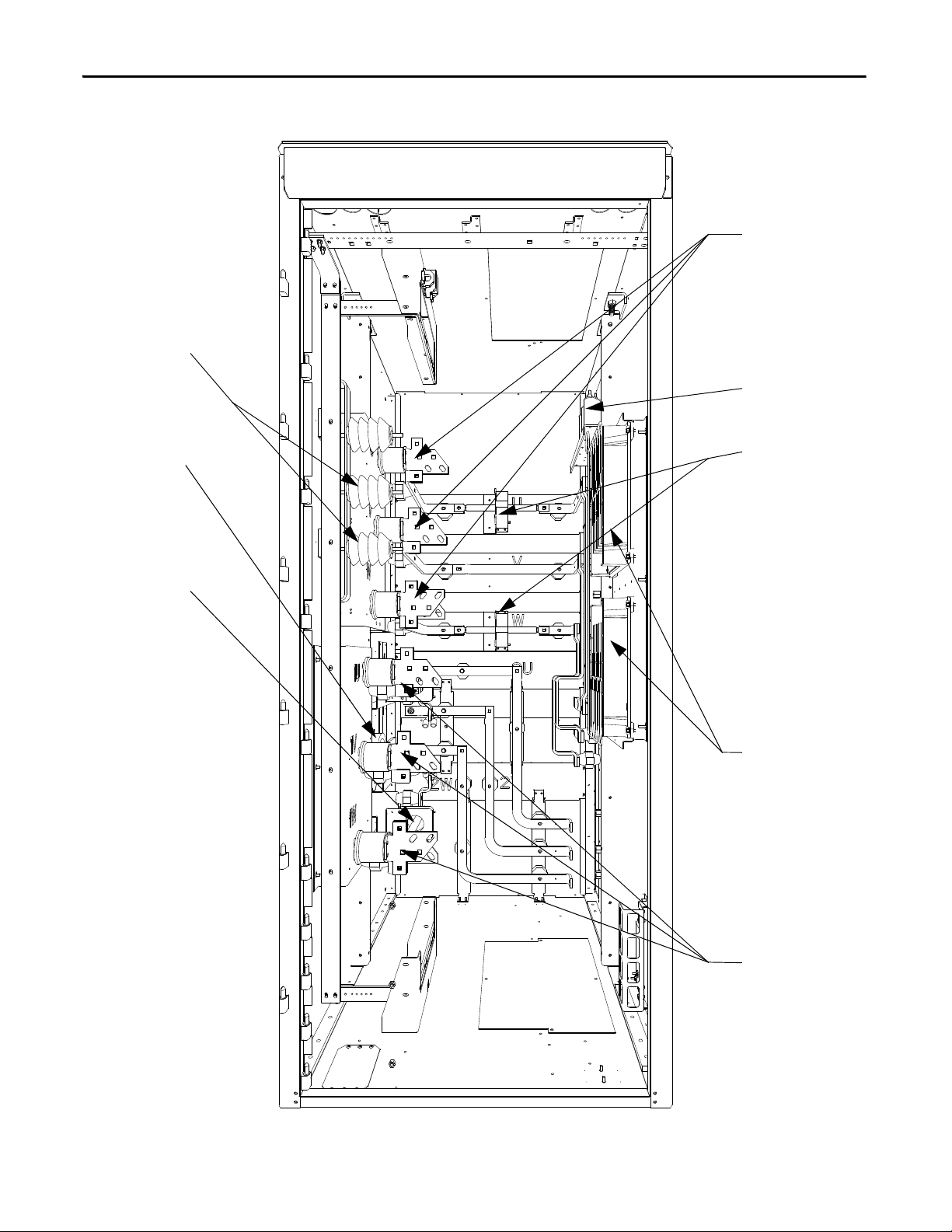
Chapter 3 Component Definition and Maintenance
Surge Arrestors
Zero Sequence
Curren t
Transformer
Current Transformer
Grounding Filter (for
use with Line Reactor)
Hall Effect Current
Sensors
Voltage Sensing Boards
Motor Terminals
Line Terminals
Figure 20 - Cabling Cabinet for AFE Rectifier (6600V heat pipe model)
28 Rockwell Automation Publication 7000-UM202B-EN-P - June 2014
Page 29
Component Definition and Maintenance Chapter 3
Hall Effect Sensor
Vol tag e Se nsi ng
Boards
Hall Effect Sensor
Curren t
Tra ns fo rm er s
Motor Terminals
Tra ns ie nt
Suppression
Network
Line Terminals
Figure 21 - Cabling cabinet for 18 Pulse rectifier (motor filter capacitors not shown)
Rockwell Automation Publication 7000-UM202B-EN-P - June 2014 29
Page 30
Chapter 3 Component Definition and Maintenance
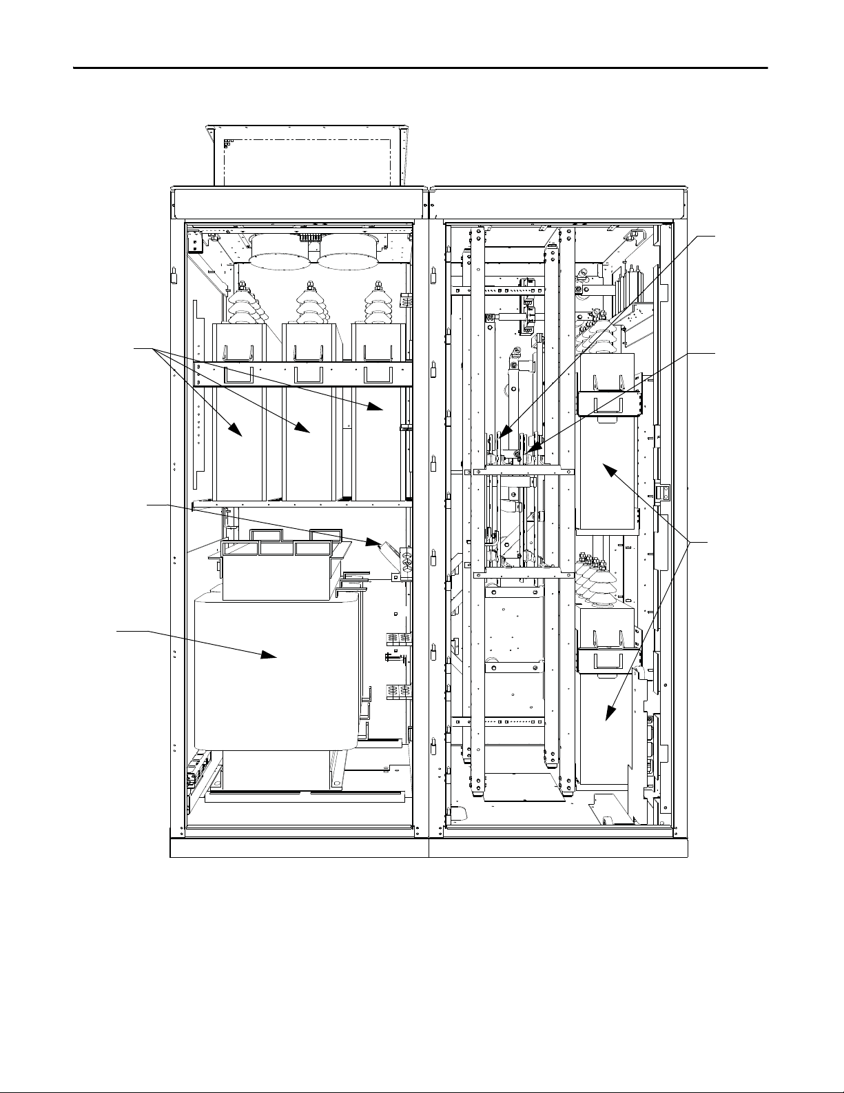
Line Filter
Capacitors
Zero Sequence
Current
Transformer
(if supplied)
Line
Reactor
Line
Terminals
Motor
Terminals
Motor Filter
Capacitor s
Figure 22 - AC line reactor cabinet with connection cabinet (heat sink model)
30 Rockwell Automation Publication 7000-UM202B-EN-P - June 2014
Page 31

Fans
Resistors
Line Reactor
Line Reactor Baffle
Component Definition and Maintenance Chapter 3
Figure 23 - AC Line Reactor Cabinet (6600V heat pipe model)
Rockwell Automation Publication 7000-UM202B-EN-P - June 2014 31
Page 32

Chapter 3 Component Definition and Maintenance
Fans
Line Filter
Capacitors
Line Reactor Baffle
Line Reactor
Resistors
Motor Filter
Capacitors
Figure 24 - AC Line Reactor with connection cabinet (heat pipe model)
32 Rockwell Automation Publication 7000-UM202B-EN-P - June 2014
Page 33

Component Definition and Maintenance Chapter 3
Voltage-Sensing Assembly
The voltage-sensing assembly consists of the voltage sensing board and the
mounting plate. The voltage sensing board has six independent channels that
convert voltages as high as 10,800V (7.2kV x 1.5 pu) down to low voltage levels
that the PowerFlex 7000 control logic (i.e. Signal Conditioning Board - SCB) can
use. To measure up to twelve independent voltage channels, link two assemblies
together, with one assembly acting as the master assembly and the second as the
slave assembly. In linked assemblies, the master assembly sends the twelve voltage
signals to the SCB board. For drives requiring the synchronous transfer option,
use one additional module.
This assembly uses a separate connector to output the transfer voltages directly to
the SCB board.
The following table shows the input voltage ranges for each input terminal on the
voltage-sensing board. There are four separate inputs taps for each independent
channel. This assembly operates at a nominal input voltage of up to 7200V with a
continuous 40% overvoltage. The output voltages scale to provide almost 10V
peak for a 140% input voltage at the high end of each of the voltage ranges.
Each channel has four taps that provide a range of input voltages and software to
provide a given amount of gain, so that 140% will correspond to the maximum
numerical value of the analogue to digital converter.
Nominal input voltage range
Tap Voltage Range
D 800...1449V
C 1450...2499V
B 2500...4799V
A 4800...7200V
ATT EN TI ON : Reconnect the grounds on the voltage sensing boards. Failure to
do so may result in injury, death or damage to equipment.
Rockwell Automation Publication 7000-UM202B-EN-P - June 2014 33
Page 34

Chapter 3 Component Definition and Maintenance
Replacing the Voltage-Sensing Circuit Board Assembly
The number of sensing boards is dependent upon the drive rectifier
configuration.
1. Verify there is no power to the equipment.
ATT EN TI ON : To prevent electrical shock, disconnect the main power before
working on the sensing board. Verify that all circuits are voltage-free, using a
hot stick or appropriate high voltage-measuring device. Failure to do so may
result in injury or death.
2. Mark the position of the ribbon cables and wires.
3. Remove the screws and lift the ring lugs from the terminals to remove the
wires.
4. Release the locking mechanism located on each side of the ribbon cable
connector and pull the ribbon cable straight out to prevent bending the
pins.
5. Remove the four nuts and washers that secure the assembly to the studs
welded to the frame.
6. Remove the old VSB and replace with the new VSB on the studs, using the
existing hardware to secure the assembly. Do not over-torque the
connections or you may break the studs.
7. Replace ring lugs on terminals. Plug in ribbon cables making sure that
cables are positioned properly and fitting is secure (locking mechanism is
engaged).
8. For personnel and equipment safety, ensure both grounding connections
are re-connected to the sensing board.
Figure 25 - Sensing board with mounting hardware placement
34 Rockwell Automation Publication 7000-UM202B-EN-P - June 2014
Page 35

Component Definition and Maintenance Chapter 3
Input Transient Protection
The drive provides input transient protection in one of two forms:
• Transient Suppression Network (TSN), or
• Surge arresters
The TSN is optimized for 18 Pulse rectifier designs. Surge arresters are optimized
for AFE and Direct-to-Drive rectifier designs.
Transient Suppression Network (TSN)
The TSN module consists of an assembly of suppressors connected to each of the
three phase input lines and the structure’s ground bus. There are three assemblies
for an 18 Pulse drive.
A transient voltage spike in excess of the semiconductor rating will destroy or
shorten the lifespan of the device. The TSN module suppresses transient
overvoltages on the drive input, and is a standard feature of the drive. The two
basic blocks of the TSN module are the MOV suppressor and the MOV fuse.
MOV Suppressor
The transient suppressors used in the module are heavy-duty metal oxide
varistors (MOVs). Varistors are voltage dependent, nonlinear resistors. They have
symmetrical voltage/current characteristics similar to back-to-back connected
Zener diodes. The varistor has very high resistance below its voltage rating and
appears as an open circuit.
The leakage current through the device would be very small in this region. When
a voltage transient occurs in which the voltage exceeds the ‘knee’ in the curve, the
varistor resistance changes from its high state by several orders of magnitude to a
very low level. The voltage is clamped for a change in current of several orders of
magnitude (Figure 26
).
Rockwell Automation Publication 7000-UM202B-EN-P - June 2014 35
Page 36

Chapter 3 Component Definition and Maintenance
10-710-610-510
-4
10
-3
10
-2
10
-1
10010
10
2
10310
4
10
5
10
-8
CURRENT (AMPERES) -log scale
VOLTAGE
(VOLTS)
log scale
High Resistance
Region
Voltage Clamping Region
Short Circuit
Region
Figure 26 - Typical MOV V-I Characteristic Curve
When the MOV clips the voltage transient, the MOV absorbs the transient
energy. The varistor has a limited energ y absorbing capability and there is
insufficient time to conduct heat out of the device. The MOV size depends on
the steady-state voltage rating, the energy in the transient, and the repetition rate
of the transients. A critical element in selecting a MOV for protection is the
impedance in the line supplying the transient. The isolation transformer or the
AC line reactor on the input of the drive provides this impedance, which is why
an impedance level is necessary for these input devices.
MOV Fuse
A medium voltage fuse is in series with each of the Phase MOVs. As seen in
Figure 27 on page 37
, these fuses may reside on either the assembly or remote
from the assembly (on the Line Terminal module). Check the part number on
your module and the information in this documentation to determine which
assembly your drive requires.
The fuses provide overload protection for the conductors feeding the suppression
network (and overturned protection if a short circuit occurs on the downstream
side of the fuse.) These conductors will normally have a much smaller current
carrying capacity than the drive input conductors; they are not protected by the
drive input fuses. The fuses also isolate a failed MOV. Varistors initially fail in a
short-circuited condition. The high follow-through current will open the fuse
and remove the MOV from the circuit.
36 Rockwell Automation Publication 7000-UM202B-EN-P - June 2014
Page 37

Component Definition and Maintenance Chapter 3
IMPORTANT
IMPORTANT
U
V
W
Drive Input Power from Line Terminals
Transient Suppression Network
Medium Voltage Input Fuses
Phase MOV Suppressor
Ground MOV Suppressor
The fuses are E-rated, current-limiting fuses with a high interrupting rating.
Because they are current-limiting, they limit both the magnitude and duration of
fault currents. They are small dimension, ferrule-type fuses with a fiberglass body,
and mount in standard fuse clips.
Rockwell Automation selects the fuses sent with the Transient Suppression
Network based on their characteristics (including internal resistance) for
optimum MOV performance and protection. Do not substitute other fuses
without contacting the factory first.
Voltage sensing occurs after the MOV fuse and will detect open fuses in the
drive control as a Master or Slave Undervoltage or Unbalance.
Figure 27 - Simplified wiring diagram
Rockwell Automation Publication 7000-UM202B-EN-P - June 2014 37
Page 38

Chapter 3 Component Definition and Maintenance
IMPORTANT
Ground location
Var ist ors
5 kV fuse example
7.2 kV fuse example
Connecting links
Var ist ors
5 kV fuse location
7.2 kV fuse location
Replacing Transient Suppression Network Fuses
Two sizes of fuses (5 kV, 7.2 kV) are available within the TSN located inside the
connection cabinet. The 18 Pulse drive contains three TSNs.
1. Ensure there is no power to the equipment.
ATT EN TI ON : To prevent electrical shock, disconnect the main power before
working on the drive. Verify that all circuits are voltage-free using a hot stick or
appropriate voltage-measuring device. Failure to do so may result in injury or
death.
2. Fuses are held in a place with a fuse clip. To remove the fuse pull firmly.
3. To replace the fuse, hold it in position and push firmly until the fuse is
seated within the fuse clip. Install fuses so that the rating is visible.
Replace the fuse with another of the same rating. (See Figure 28 on page 38 for
location.)
Figure 28 - Transient Suppression Network
38 Rockwell Automation Publication 7000-UM202B-EN-P - June 2014
Page 39

Component Definition and Maintenance Chapter 3
Replacing Metal-Oxide Varistors
Metal-oxide varistors (MOV) are part of the TSN located within the connection
cabinet.
1. Ensure there is no power to the equipment.
ATT EN TI ON : To prevent electrical shock, disconnect the main power before
working on the drive. Verify that all circuits are voltage-free using a hot stick or
appropriate voltage-measuring device. Failure to do so may result in injury or
death.
2. Observe the locations of the connecting links.
3. Detach the connecting links by removing the screws.
4. Using a screwdriver remove the screws at the base.
5. Replace the MOV (polarity is not an issue).
6. Continue by replacing the screws and connecting links.
Each MOV panel is grounded. Ensure that one MOV (see Figure 28 on page 38
for location) connects to the grounding lead.
Surge Arresters
These medium voltage drives use heavy duty distribution class surge arresters for
transient overvoltage protection in the drives with AFE rectifiers. The arresters
are certified as per ANSI/IEEE Std C62.11-1993.
The surge arresters are MOVs, with or without an air gap in series, in sealed
housing. They provide overvoltage protection similar to that of the TSN module.
They differ from the TSN in that fusing is not mandatory for the operation of
surge arresters.
There are three types of surge arresters depending on the voltage class of the
drive:
Drive Voltage 2.4 kV 3.3 kV, 4.16 kV, 4.8 kV 6.0...6.9 kV
Arrester rating (RMS) 3 kV 6 kV 9 kV
Arrester MCOV (RMS) 2.55 5.10 7.65
The most severe temporary overvoltage occurs when one phase is grounded in an
ungrounded system. The full line-to-line voltage applies to the arrester in this
case. The arresters operate under this condition continuously without any
problems as indicated by their Maximum Continuous Operating Voltage
(MCOV) rating.
Rockwell Automation Publication 7000-UM202B-EN-P - June 2014 39
Page 40

Chapter 3 Component Definition and Maintenance
W
V
Drive Input from Line Terminals
Heavy-duty
Distribution Class
Surge Arrestor
Three Y-connected surge arresters attach to the incoming MV lines. The neutral
point of the arresters connects to the ground bus.
Figure 29 - Surge arresters on incoming MV lines
U
Operation
Arrester operation without a gap is the same as that of MOVs in the TSN.
Depending on design, the arrester may also have a gap. Both gapped and ungapped arresters provide adequate overvoltage protection.
The arresters can withstand most commonly-seen bus transients within their
capability. If there is a harmonic filter on the MV bus connected to the drive, the
filter must satisfy relevant international or local standards, such as IEEE Std
1531— Clause 6.4, to avoid high inrush currents.
The surge arrester is certified as per ANSI/IEEE Std C62.11-1993. Certification
tests include high current short duration tests, low current long duration tests,
and fault current withstand tests. The fault current withstand tests consist of
different combinations of kA and number of cycles, including a 20kA 10-cycle
test, under which the arresters are non-fragmenting without expelling any
internal components.
When the incoming energy exceeds the handling capability of the arrester and
causes arrester failure, the housing splits open to vent without causing damage to
any adjacent components.
40 Rockwell Automation Publication 7000-UM202B-EN-P - June 2014
Page 41

Component Definition and Maintenance Chapter 3
Surge Arresters
Replacing the Surge Arrester
1. Isolate and lock out all power to the drive.
ATT EN TI ON : To prevent electrical shock, disconnect the main power before
working on the drive. Verify that all circuits are voltage-free using a hot stick or
appropriate voltage-measuring device. Failure to do so may result in injury or
death.
2. Wait a minimum of ten minutes for the drive to discharge stored energy.
3. Observe the location of the connecting leads.
4. Use proper method to ensure the leads are at ground potential. Use
temporary grounding when necessary.
5. Detach the connecting leads.
6. Loosen the bolt that attaches the surge arrester to the ground bus. Remove
the arrester. Remove temporary ground when applicable.
7. Replace the surge arrester with an equivalent one (make sure that the
voltage rating is the same).
8. Connect the leads to the surge arrester.
9. Torque the surge arrester hardware to 28 N•m (21 lb•ft).
Figure 30 - Surge Arresters (heat sink model)
Rockwell Automation Publication 7000-UM202B-EN-P - June 2014 41
Page 42

Chapter 3 Component Definition and Maintenance
Surge Arresters
Figure 31 - Surge Arresters (heat pipe model)
When you disconnect the surge arrester from drive, the arrester may retain a small
amount of static charge. As a precautionary measure, install a temporary ground
on the line-end of the arrester and discharge the stored energy. Remove
temporary ground before reinstalling the arrester. To avoid electrical shock when
removing the arrester from service, treat it as fully energized until you disconnect
both the line and ground leads.
Field Test and Care
No field testing is necessary. The arresters do not require special care. At very
dusty sites, however, you should clean the arrester when cleaning the entire drive.
42 Rockwell Automation Publication 7000-UM202B-EN-P - June 2014
Page 43

Component Definition and Maintenance Chapter 3
IMPORTANT
Replacing Output Grounding Network Capacitors
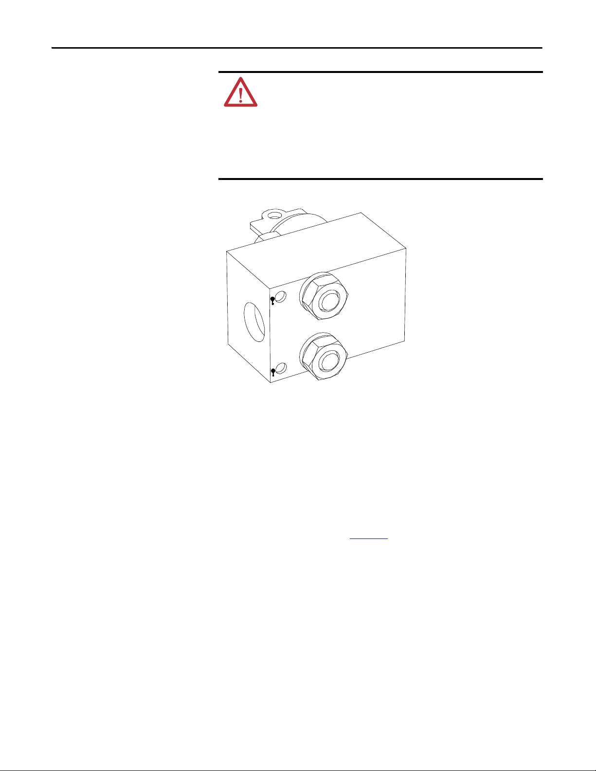
PowerFlex 7000 18 Pulse and select AFE drives come with an installed grounding
network.
The number of capacitors varies depending on the system voltage.
1. Isolate and lock out all power to the drive.
ATT EN TI ON : To prevent electrical shock, disconnect the main power before
working on the drive. Verify that all circuits are voltage-free using a hot stick or
appropriate voltage-measuring device. Failure to do so may result in injury or
death.
2. Note the position of the leads.
3. Remove the 6.4 mm (¼ in.) hardware and disconnect the leads connected
to the terminals.
4. Four brackets secure the capacitor. Loosen the four screws at the base of
the brackets and lift the capacitor out.
5. Place the new capacitor and tighten the screws securely.
6. Replace the ring lugs and 6.4 mm (¼ in.) hardware (see Figure 31
The maximum torque for the capacitor terminal is 3.4 N•m (30 lb•in).
Figure 32 - Capacitor in grounding network
).
Rockwell Automation Publication 7000-UM202B-EN-P - June 2014 43
Page 44
Chapter 3 Component Definition and Maintenance
IMPORTANT
Replacing the Hall Effect Current Sensor (HECS)
1. Isolate and lock out all power to the drive.
ATT EN TI ON : To prevent electrical shock, disconnect the main power before
working on the drive. Verify that all circuits are voltage-free using a hot stick or
appropriate voltage-measuring device. Failure to do so may result in injury or
death.
2. Note the location of all wires and the orientation of the HECS. For quick
reference when checking the orientation of the HECS, look for the white
arrow.
The Hall Effect Current Sensor (HECS) and wires must be in the proper
orientation. Note the position before disassembly.
3. Remove the round bus bar. Remove the M10 hardware and slide the bar
out.
4. Remove the output connector. Note the orientation.
5. Remove the four screws on the base of the Hall Effect sensor and remove
the sensor.
6. Insert the new sensor. Orient the arrows as shown in Figure 34
.
7. Slide the bus bar back into place and secure with the M10 hardware.
8. Replace the output connector, noting the correct orientation.
44 Rockwell Automation Publication 7000-UM202B-EN-P - June 2014
Page 45
Component Definition and Maintenance Chapter 3
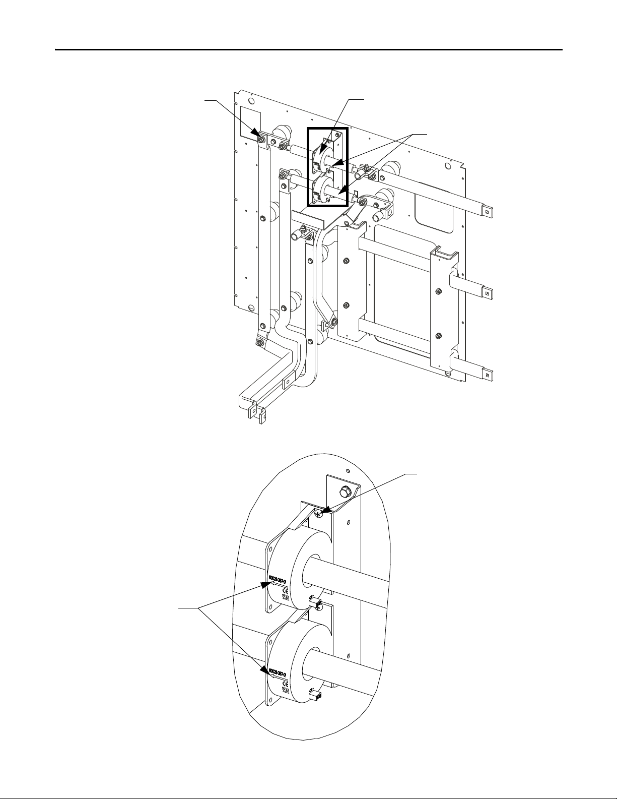
Bus Bar
Hall Effect
Current Sensor
M10 Hardware
Base H ardware
Arrows must be
oriented properly
Figure 33 - Hall Effect Current Sensor located within cabinet
Figure 34 - Hall Effect Current Sensor (detail)
Rockwell Automation Publication 7000-UM202B-EN-P - June 2014 45
Page 46

Chapter 3 Component Definition and Maintenance
IMPORTANT
Replacing the Current Transformer (CT)
1. Isolate and lock out all power to the drive.
ATTENTION: To prevent electrical shock, disconnect the main power before
working on the drive. Verify that all circuits are voltage-free using a hot stick or
appropriate voltage-measuring device. Failure to do so may result in injury or
death.
2. Note the location of all wires and the orientation of the CT. For quick
reference when checking the orientation of the CT, look for the white dot.
The CT and wires must be in the proper orientation. Note the position before
disassembly.
3. Disconnect the wires.
4. Disassemble the bus bar to remove the CT. Remove the M10 hardware to
slide out the bus bar.
Filter Capacitor Cabinet
5. Remove the four screws located in the base of the CT and remove the CT.
6. Replace the CT, ensuring the proper orientation. Fasten the CT securely
with the four screws in the base
7. Reconnect the ring lugs. Do not overtighten or you will break the threaded
stud. For torque specifications, refer to Torque Requirements for
Threaded Fasteners on page 183. Replace the bus bar and tighten into
place.
Filter Capacitors
All “B” Frame drives use filter capacitors on the motor side. The AFE rectifier
options also include filter capacitors on the line side. Refer to Figure 19 on
page 27 (Cabling Cabinet for AFE Rectifier) and Figure 21 on page 29 (Cabling
Cabinet for 18 Pulse Rectifier).
The filter capacitors are three-phase, oil-filled, four-bushing units. The threephase capacitors are internal single-phase units connected in a Y configuration.
The neutral point of the Y connects to the fourth bushing, which is available to
use as a neutral point voltage measurement or other protection/diagnostics
purposes. The metal cases of the capacitors are grounded through a stud on the
capacitor housing.
The capacitors have internal “bleeding resistors” to discharge the capacitor and
reduce its voltage below 50V in five minutes when disconnected. Figure 35
a typical three-phase capacitor.
46 Rockwell Automation Publication 7000-UM202B-EN-P - June 2014
shows
Page 47

Figure 35 - Motor filter capacitor
IMPORTANT
Component Definition and Maintenance Chapter 3
WARNING: Allow 5...10 minutes for motor capacitors to safely discharge
voltage prior to opening cabinet doors.
Replacing Filter Capacitors
See Publication 7000-IN010_-EN-P, “Handling, Inspection, and Storage of
Medium Voltage Line Filter Capacitors”.
1. Isolate and lock out all power to the drive.
ATT EN TI ON : To prevent electrical shock, disconnect the main power before
working on the drive. Verify that all circuits are voltage-free using a hot stick or
appropriate voltage-measuring device. Failure to do so may result in injury or
death.
2. Note the location of all the cables and mark them accordingly.
3. Remove the 4 power connections to the terminals, and the single ground
connector from the drive to the capacitor frame, located at the back top
right corner of the capacitor.
4. Remove the front bracket that holds the capacitor in place. At the rear of
the capacitor, there is no hardware securing the capacitor; it fits into a slot
in the assembly.
5. Remove the capacitor from the drive.
Capacitors can weigh as much as 100 kg (220 lbs). Use two or more people to
remove a capacitor.
Rockwell Automation Publication 7000-UM202B-EN-P - June 2014 47
Page 48

Chapter 3 Component Definition and Maintenance
ATT EN TI ON : The porcelain bushings are extremely fragile and any force applied
to the bushings can damage the seal between the bushing and the body
causing potential leaks or chipping.
6. Install the new capacitor, sliding it back until it fits into the slot. Fasten the
front bracket.
7. Reconnect all the power cables and the ground connection. These use
M14 hardware, but should only be tightened to 30 N•m (22 lb•ft) due to
capacitor mechanical constraints. You may want to fasten these
connections before fully sliding the capacitor into place depending on the
available space.
8. Follow the instruction labels on each capacitor to tighten the terminal
connections.
9. Reinstall the removed sheet metal, and complete one final check to ensure
connections are secure and correct.
Testing Filter Capacitors
There are two ways to test line filter capacitors. Rockwell Automation
recommends the first method as it reduces the chance of re-torque issues because
the capacitors are not disconnected. If the readings are unsatisfactory, the second
method is more accurate, but involves disconnecting and testing them
individually.
First Method
1. Ensure there is no power to the equipment.
ATT EN TI ON : To prevent electrical shock, disconnect the main power before
working on the drive. Verify that all circuits are voltage-free using a hot stick or
appropriate voltage-measuring device. Failure to do so may result in injury or
death.
ATT EN TI ON : Verify the load is not running due to process. A freewheeling
motor can generate voltage that feeds back to the equipment.
2. Follow appropriate safety steps to isolate the equipment from medium
voltage.
3. Verify that there is no voltage present on the capacitor by using a hot stick
or any other appropriate voltage-measuring device.
4. Perform visual inspection to ensure there is no oil leak or bulge in any of
the capacitors.
48 Rockwell Automation Publication 7000-UM202B-EN-P - June 2014
Page 49

Component Definition and Maintenance Chapter 3
ATT EN TI ON : Capacitors that appear bulged or are leaking oil indicate potential
problems with the internal elements. DO NOT USE. These units must be
replaced. Failure to do so may lead to personal injury or death, property
damage, or economic loss.
5. Using a DMM measure the capacitance across each phase-to-neutral of
capacitors without removing any connections.
If the difference between the highest and the lowest readings is below 15%,
then all capacitors are in good condition. If the difference between the
highest and the lowest readings is off by 15% or more, then you might have
a bad capacitor. If more than one capacitor is used in the circuit, then you
would need to isolate each of them and check them separately to identify
which one is defective.
6. Before disconnecting the capacitors, note the location of all the cables and
mark them accordingly.
7. Disconnect power cables from the capacitor terminals on all four bushings
and isolate them from the capacitor (see Replacing Filter Capacitors
on
page 47).
8. Repeat step 5 to check each capacitor separately to confirm which is
defective.
Second Method
1. Ensure there is no power to the equipment.
ATT EN TI ON : To prevent electrical shock, disconnect the main power before
working on the drive. Verify that all circuits are voltage-free using a hot stick or
appropriate voltage-measuring device. Failure to do so may result in injury or
death.
ATT EN TI ON : Verify the load is not running due to process. A freewheeling
motor can generate voltage that feeds back to the equipment.
2. Perform visual inspection to ensure there is no oil leak or bulge in any of
the capacitors.
ATT EN TI ON : Capacitors that appear bulged or are leaking oil indicate potential
problems with the internal elements. DO NOT USE. These units must be
replaced. Failure to do so may lead to personal injury or death, property
damage, or economic loss.
3. Note the location of all the cables and mark them accordingly.
4. Disconnect power cables from the capacitor terminals on all four bushings
and isolate them from the capacitor (see Replacing Filter Capacitors
on
page 47).
Rockwell Automation Publication 7000-UM202B-EN-P - June 2014 49
Page 50

Chapter 3 Component Definition and Maintenance
5. Connect a low voltage single-phase test power, for instance 110V or 220V,
across a phase and the neutral of the capacitor. Switch on the test power
and measure the test voltage and current drawn by the capacitor. Repeat
the test for all three phases and note down the test voltage and current.
ATT EN TI ON : The capacitor will charge during this test so take care to prevent a
shock or injury. When moving the test connections from one phase to the next,
wait five minutes minimum for the capacitor to discharge.
6. Calculate the capacitance from the measured values of test voltage and
current. For a good capacitor, the calculated capacitance value for each of
the three readings should be within ±15% of the capacitor nameplate
micro-Farad. If it is outside this range, the capacitor must be replaced.
Suppose a capacitor under test is rated at 400 kVAR, 6600V, 50 Hz, 29.2 F.
Assume you are using 200V, 50 Hz test power with the recorded voltage and
current values for each test as shown in the table below.
Phase - Neutral L1-N L2-N L3-N
Test Voltage 200V 200V 200V
Measured Current 1.87 A 1.866 A 1.861 A
Converter Cabinet Components
Calculate the capacitance using the first reading. In this case:
V = 200V, I = 1.87 for L1-N
Xc = V/I = 200/1.87 = 106.95
C= 1/ (2
π F Xc)
Where:
F = frequency of the applied voltage.
C= 1/(2 x 3.14 x 50 x 106.95
C=29.7 F
Similarly, you can calculate the capacitance for the remaining two measurements
for L2-N and L3-N.
This section describes the converter cabinet components of your PowerFlex 7000
“B” Frame drive. It also details a number of regular or recurring maintenance
tasks that will keep your drive in peak operating condition.
The converter cabinet contains three rectifier modules and three inverter
modules. Isolated Gate Driver Power Supplies (IGDPS) are available on the
cabinet’s right side sheet.
Thermal sensors are available on the top module of the inverter and rectifier. The
exact location depends on the drive configuration. These sensors connect to
temperature feedback boards that return signals to the drive control.
For control/cabling cabinets, see Control / Cabling Cabinet Components
page 25. For DC link/fan cabinets, see DC Link and Fan Cabinet Components
on page 111.
50 Rockwell Automation Publication 7000-UM202B-EN-P - June 2014
on
Page 51

Isolated Gate Driver Power
Supplies (IGDPS)
Rectifier IGDPS not
required in drives with
SPS boards installed
Ground Bus
Inverter Modules
Differential Pressure
Sensor
Rectifier Modules
Component Definition and Maintenance Chapter 3
Figure 36 - Converter cabinet (heat sink model, 2400V)
Rockwell Automation Publication 7000-UM202B-EN-P - June 2014 51
Page 52

Chapter 3 Component Definition and Maintenance
Isolated Gate
Driver Power
Supplies (IGDPS)
Rectifier IGDPS not
required in drives with
SPS boards installed
Ground Bus
Inverter Modules
Differential Pressure
Sensor
Rectifier Modules
Figure 37 - Converter cabinet (heat sink model, 3300...4160V version shown)
52 Rockwell Automation Publication 7000-UM202B-EN-P - June 2014
Page 53

Component Definition and Maintenance Chapter 3
Differential Pressure
Sensor
Ground Bus
Isolated Gate Driver
Power Suppli es
(IGDPS)
Rectifier IGDPS not
required in drives with
SPS boards installed
Rectifier Modules
Inverter Modules
Figure 38 - Converter cabinet (heat sink model, 6600V version shown)
Rockwell Automation Publication 7000-UM202B-EN-P - June 2014 53
Page 54

Chapter 3 Component Definition and Maintenance
Isolated Gate
Driver Power
Supplies (IGDPS)
Isolated Gate
Driver Power
Supplies (IGDPS)
Rectifier modules
Inverter modules
Ground bus
Rectifier modules
Isolated Gate
Driver Power
Supplies
(IGDPS)
Isolated Gate
Driver Power
Supplies
(IGDPS)
Inverter modules
Figure 39 - Converter Cabinet, 3300...4160V (heat pipe model)
Figure 40 - Converter Cabinet, 6600V (heat pipe model)
54 Rockwell Automation Publication 7000-UM202B-EN-P - June 2014
Page 55

Component Definition and Maintenance Chapter 3
PowerCage™ Overview
A PowerCage is a converter module, consisting of the following elements:
• epoxy resin housing
• power semiconductors with gate driver circuit boards
• heat sinks or heat pipes
• clamp
• snubber resistors
• snubber capacitors
• sharing resistors (not applicable for 2400V models)
Each drive consists of three PowerCage rectifier modules and three PowerCage
inverter modules. There are two principal classes of rectifiers:
• AFE and 18 Pulse
– AFE type rectifiers use SGCTs
– 18 Pulse rectifiers use SCRs
All inverter modules use SGCTs as semiconductors.
The size of the PowerCage depends on the system voltage, and the components
will also vary in the system current.
This table illustrates power semiconductor usage in the converter section.
Configuration Rectifier SGCTs Rectifier SCRs Inverter SGCTs
2400V, AFE 6 0 6
2400V, 18 Pulse 0 18 6
3300/4160V, AFE 12 0 12
3300/4160V, 18 Pulse 0 18 12
6600V, AFE 18 0 18
6600V, 18 Pulse 0 18 18
Some PowerFlex 7000 configurations contain Self-Powered SGCT Power Supply
(SPS) boards. These boards are applicable on all “A” Frame drives and all AFE “B”
Frame drives with heat sinks. See Self-Powered SGCT Power Supply - SPS
on
page 101 for more information
ATT EN TI ON : To prevent electrical shock, disconnect the main power before
working on the drive. Verify that all circuits are voltage-free, using a hot stick or
appropriate voltage-measuring device. Failure to do so may result in injury or
death.
ATT EN TI ON : The PowerCage can house either SCRs or Symmetrical Gate
Commutated Thyristors (SGCT). The SGCT circuit board is sensitive to static
charges. Never handle these boards without proper grounding.
ATT EN TI ON : Some circuit boards can be destroyed by static charges. Use of
damaged circuit boards may also damage related components. Use a grounding
wrist strap when handling sensitive circuit boards.
ATT EN TI ON : If equipped, the SPS circuit board is sensitive to static charges. Do
not handle these boards without proper grounding.
Rockwell Automation Publication 7000-UM202B-EN-P - June 2014 55
Page 56

Chapter 3 Component Definition and Maintenance
Resistance Checks
Prior to applying control power to the drive, power semiconductor and snubber
circuit resistance measurements must be taken. Doing so will ensure that no
damage has occurred to the converter section during shipment. The instructions
provided below detail how to test the following components:
• Inverter or AFE Rectifier Bridge
– Anode-to-Cathode Resistance Test (Sharing Resistor and SGCT)
– Snubber Resistance Test (Snubber Resistor)
– Snubber Capacitance Test (Snubber Capacitor)
• SCR Rectifier Bridge
– Anode-to-Cathode Resistance Test (Sharing Resistor and SCR)
– Gate-to-Cathode Resistance Test (SCR)
– Snubber Resistance Test (Snubber Resistor)
– Snubber Capacitance Test (Snubber Capacitor)
ATT EN TI ON : Before attempting any work, verify that the system has been
locked out and tested to have no potential.
Snubber Resistors
Snubber resistors connect in series with the snubber capacitors. Together they
form a simple RC snubber that connects across each thyristor (SCR or SGCT).
The snubber circuit reduces the dv/dt stress on the thyristors and reduces the
switching losses. The snubber resistors connect as sets of various wire-wound
resistors connected in parallel. The number of resistors in parallel depends on the
type of the thyristor and the configuration and frame size of the drive.
Snubber Capacitors
Snubber capacitors are connected in series with the snubber resistors. Together
they form a simple RC snubber that is connected across each thyristor (SGCT).
The purpose of the snubber circuit is to reduce the voltage stress (dv/dt and
peak) of the thyristor and to reduce the switching loss.
Sharing Resistors
Sharing resistors provides equal voltage sharing when using matched devices in
series. Please note, SGCT PowerCages for 2400V systems do not need matched
devices and have no sharing resistor.
SCR PowerCages always have sharing resistors even if matched devices are not
necessary. Sharing resistors in SCR PowerCages provide a diagnostic function.
56 Rockwell Automation Publication 7000-UM202B-EN-P - June 2014
Page 57

Component Definition and Maintenance Chapter 3
Rsn-2
Rsn-1
Anode
Cs-1
Rsh
Cs-2
Snubber
Resistor
Test
Cathode
Heatsink Heatsink
Rsn-2
Rsn-1
Anode
Cs-1
Rsh
Cs-2
Snubber
Resistor
Test
Cathode
Heatsink Heatsink
SPS Board
J1-1
J1-2
SGCT and Snubber Circuit
With all power semiconductors or thyristors, the SGCT requires a snubber
circuit. The snubber circuit for the SGCT consists of a snubber resistor in series
with a snubber capacitor.
Figure 41
shows the snubber circuit. Figure 51 shows the physical locations of the
same circuit. Measure the resistance across two adjacent heat sinks. A value
between 60 kΩ and 75 kΩ indicates a good sharing resistor.
Figure 41 - Snubber Circuit for SGCT module
Figure 42 - Snubber Circuit for SGCT module (with SPS board)
Rockwell Automation Publication 7000-UM202B-EN-P - June 2014 57
Page 58

Chapter 3 Component Definition and Maintenance
Clamp Base
SGCTs
Heat sink
Module
Housing
Tem p er at u re
Feedba ck Board
Clamp Head
Clamp Base
Heat sink
Module Housing
SPS Board
Mounting
Assembly
without
Temperature
Feedback
Board
Clamp Head
SGCT
SPS Mounting Assembly with
Temperature Feedback Board
SGCT
Figure 43 - 2400V Two Device PowerCage (heat sink model)
Figure 44 - 2400V Two Device PowerCage (with SPS Boards installed)
58 Rockwell Automation Publication 7000-UM202B-EN-P - June 2014
Page 59

Component Definition and Maintenance Chapter 3
Clamp Base
Matched Set
Two SGC Ts
Matched Set
Two SGC Ts
Heat sink
Module Housing
Temperature Feedback Board
Clamp Head
Clamp Base
Matched Set
Two SGC Ts
SPS Mounting Assembly with
Temperature Feedback Board
Matched Set
Two SGC Ts
Clamp Head
Heat sink
SPS Mounting Board Assembly without
Temperature Feedback Board
Module Housing
Figure 45 - 3300/4160V Four Device PowerCage (heat sink model)
Figure 46 - 3300/4160V Four Device Rectifier PowerCage (with SPS Boards installed)
Rockwell Automation Publication 7000-UM202B-EN-P - June 2014 59
Page 60

Chapter 3 Component Definition and Maintenance
Clamp Base
Matched Set
Three SGCTs
Matched Set
Three SGCTs
Clamp Head
Heat sink
Temperature Feedback Board
Module Housing
Clamp Base
Matched Set
Three SGCTs
Matched Set
Three SGCTs
Clamp Head
Heatsink
SPS Mounting Assembly with
Temperature Feedback Board
SPS Mounting Assembly without
Temperature Feedback Board
Module
Housing
Figure 47 - 6600V Six Device PowerCage (heat sink model)
Figure 48 - 6600V Six Device PowerCage (with SPS Boards installed)
60 Rockwell Automation Publication 7000-UM202B-EN-P - June 2014
Page 61

Component Definition and Maintenance Chapter 3
Heat Pipe Suppor t Channel
Module Housing
Clamp Base
Matched Set
Two SGC Ts
Tem p er at u re
Feedback Board
Matched Set
Two SGC Ts
Clamp Head
Heat Pipe Assembly
Figure 49 - 3300/4160V Four Device PowerCage (heat pipe model)
Rockwell Automation Publication 7000-UM202B-EN-P - June 2014 61
Page 62

Chapter 3 Component Definition and Maintenance
Cs-1
Rsh
Rsn-2
Rsn-1
Anode
Cs-2
Cathode
Rsn-2
Cs-1
Cs-2
Rsn-1
Cathode
Rsh
Anode
Figure 50 - Snubber Circuit Assembly for SGCT module
Figure 51 - Snubber Circuit Assembly (heat pipe model)
62 Rockwell Automation Publication 7000-UM202B-EN-P - June 2014
Page 63

Component Definition and Maintenance Chapter 3
In addition to the snubber circuit, a sharing resistor connects in parallel with the
SGCT. The sharing resistor ensures the voltage’s equal distribution among
SGCTs connected in series. Connect SGCTs in series to increase the total reverse
voltage blocking (PIV) capacity, as seen by the electrical circuit. A single SGCT
has a PIV rating of 6500V. This single device provides sufficient design margin
for electrical systems with 2400V medium voltage supply. At 4160V, connect two
SGCTs in series to provide a net PIV of 13,000V to achieve the necessary design
margin. Similarly, connect three SGCTs in series at 6.6 kV, providing a net PIV of
19,500V to achieve the necessary design margin.
To meet the cooling requirements of the SGCT, place the SGCT between two
forced air-cooled heat sinks, one heat sink on the anode and the other heat sink
on the cathode. The force on the SGCTs differs with the size of the device. The
clamp assembly on the right hand side of the inverter module generates these
forces.
The SGCTs require uniform pressure to prevent damage and to ensure low
thermal resistance. Achieve uniform pressure by loosening the heat sink
mounting bolts, tightening the clamp, then tightening the heat sink bolts.
This design directs external filtered air through the heat sink slots to dissipate
heat from the SGCTs. The door filter ensures the heat sink slots stay clear of
dust particles.
SGCT Testing
The following steps outline how to verify SGCT semiconductors and all
associated snubber components. A quick reference to the expected resistance and
capacitance values as well as a simple schematic diagram is located in the table
below. A simple schematic diagram in Figure 41 on page 57
snubber components are connected across an SGCT.
SGCT Rating Sharing Resistor¹ Snubber Resistor Snubber Capacitor
1500 A 80 kΩ 6 Ω (AFE Rectifier) 0.2 μf
1500 A 80 kΩ 7.5 Ω (Inverter) 0.2 μf
800 A 80 kΩ 10 Ω 0.1 μf
400 A 80 kΩ 15 Ω (AFE Rectifier) 0.1 μf
400 A 80 kΩ 17.5 Ω (Inverter) 0.1 μf
¹— 2400V drives will not have a sharing resistor on devices.
shows how the
Table 1 - SGCT/snubber resistance values
SGCT Resistance Measurement Measured Resistance
Inverter Rectifier (AFE only)
SGCT Anode-Cathode Resistance (heat sink to heat sink) k-Ω
(Lowest) (Highest) (Lowest) (Highest)
Snubber Resistance (Test point: Heat sink above) Ω
(Lowest) (Highest) (Lowest) (Highest)
Snubber Capacitance (Test Point – heat sink on Right) μF
(Lowest) (Highest) (Lowest) (Highest)
Rockwell Automation Publication 7000-UM202B-EN-P - June 2014 63
Page 64

Chapter 3 Component Definition and Maintenance
Resistance value between two
heat sinks is sharing resistance in
parallel with anode-cathode
resista nce
Resistance value between
heat sink and test point is
snubber resistance
SGCT Anode-to-Cathode (Sharing) Resistance
The anode-cathode resistance check measures the parallel combination of the
sharing resistor and SGCT anode-cathode resistance. The sharing resistor has a
resistance much lower than that of a good SGCT, so the measurement will be
slightly less than the resistance of the sharing resistor. A measurement between
60 kΩ and 75 kΩ indicates the SGCT is in good condition and that wiring to
the SGCT is correct. If the SGCT fails, it will be in the shorted mode, 0 Ω. The
anode-to-cathode resistance check will be 0 Ω.
There is a test point inside the PowerCage to measure the resistance of the
snubber resistor and capacitance of the snubber capacitor. The test point is the
electrical connection between the snubber resistor and snubber capacitor. Place
one probe of the multi-meter on the test point and the other probe on the
appropriate heat sink to determine the value of the resistor or capacitor. See
Figure 52
Figure 52 - SGCT PowerCage
.
64 Rockwell Automation Publication 7000-UM202B-EN-P - June 2014
Page 65

Component Definition and Maintenance Chapter 3
Resistance value between two
heat sinks is sharing resistance
in parallel with anode-cathode
resista nce
Resistance value
between heat sink and
test point is snubber
resistance
Snubber Test Point
Resistance between
heat sink and test
point is snubber
resistance
Resistance between
two heat sinks is
sharing resistance in
parallel with anodecathode resistance
Figure 53 - Resistance Measurements SGCT PowerCage (with SPS Board Mounting Assembly)
Figure 54 - Resistance Measurements (heat pipe model)
Rockwell Automation Publication 7000-UM202B-EN-P - June 2014 65
Page 66

Chapter 3 Component Definition and Maintenance
Snubber test point
Measure resistance
between heat sink
and test point
Heatsink Heatsink
SGCT
Snubber
Resistor
Snubber
Capacitor
Sharing Resistor
Tes t Po in t
Resistance value between
heat sink and test point is
Snubber Resistance
Heatsink H eatsink
Snubber
Resistor
Snubber
Capacitor
Sharing Resistor
J1
SPS Board
1
2
SGCT
Tes t Po int
Resistance Value between two
heat sinks is sharing resistance
in parallel with Anode-Cathode
Resistance
Snubber Resistance (SGCT Device)
Access to the snubber resistor is not required to test the resistance. The snubber
circuit test point is located within the PowerCage under the heat sinks. For each
device, there is one test point. To verify the resistance, measure the resistance
between the test point and the heat sink above.
Figure 55 - Snubber resistor test
Figure 56 - Snubber Resistor Test (with SPS Board)
66 Rockwell Automation Publication 7000-UM202B-EN-P - June 2014
Page 67

Component Definition and Maintenance Chapter 3
Heatsink Heatsink
Snubber
Resistor
Snubber
Capacitor
Sharing Resistor
SGCT
Tes t Po in t
Measure capacitance
between heat sink
and test point (or
from heat sink to
heat sink)
Snubber test point
Refer to Tab l e 1 on p ag e 6 3 to determine the appropriate snubber resistance value
for the current rating of the SGCT used.
If the resistor is found to be out of tolerance, refer to page page 72
for detailed
instructions on replacing the snubber resistor assembly.
Snubber Capacitance (SGCT Device)
Turn the multimeter from the resistance to capacitance measurement mode.
Verify the snubber capacitor by measuring from the test point to the heat sink
adjacent to the right for standard rectifiers, or from heat sink to heat sink. For
SPS rectifiers, measure from the test point to pin 1 of the Phoenix connector that
plugs into J1 of the SPS board (disconnect the J1 connector from the SPS board
first).
Figure 57 - Snubber Capacitor Test
Rockwell Automation Publication 7000-UM202B-EN-P - June 2014 67
Page 68

Chapter 3 Component Definition and Maintenance
Heatsink Heatsink
Snubber
Resistor
Snubber
Capacitor
Sharing Resistor
J1
SPS Board
1
2
SGCT
Tes t Po in t
Snubber Capacitor Wire
Use Connector Terminal Screw
for Testing Snubber Capacitor
SGCT Cathode Wire
Snubber Test Point
Figure 58 - Snubber Capacitor Test (shown with SPS Board installed)
Refer to Tab le 1 on p ag e 63 to determine the appropriate snubber capacitance
value for the current rating of the SGCT used.
The capacitance measured is actually affected by the snubber capacitor and other
capacitance in the circuit, including capacitance from the gate driver circuit. You
are actually looking for a consistent reading for all devices.
If the capacitor is out of tolerance, refer to page 76
for detailed instructions on
how to replace the snubber capacitor.
68 Rockwell Automation Publication 7000-UM202B-EN-P - June 2014
Page 69

Component Definition and Maintenance Chapter 3
IMPORTANT
Replacing the SGCT
The SGCT (“device”) with attached circuit board is located within the
PowerCage assembly. You must replace SGCTs in matched sets (2 sets for 4160V,
3 sets for 6600V).
The SGCT and associated control board are a single component. Never change
the device or the circuit board individually. There are four LEDs on the SGCT,
and the following table describes their functions.
LED 4 Green Solid Green indicates that the Power Supply to the Card is OK
LED 3 Green Solid Green indicates that the Gate-Cathode resistance is OK
LED 2 Yellow LED ON indicates the gate is ON, and Flashes alternately with LED 1 while gating
LED 1 Red LED ON indicates the gate is OFF, and Flashes alternately with LED 2 while gating
1. Isolate and lock out all power to the drive.
ATT EN TI ON : To prevent electrical shock, disconnect the main power before
working on the drive. Verify that all circuits are voltage-free using a hot stick or
appropriate voltage-measuring device. Failure to do so may result in injury or
death.
2. Note the position of the fiber optic cables for assembly.
3. To remove the SGCT, remove the gate driver power cable and fiber optic
cables. Exceeding the minimum bend radius (50 mm [2 in.]) of the fiber
optic cables may result in damage.
Remove the SPS snubber connector ( J1 on the SPS board) and remove the
SPS mounting bracket with the SPS board, if installed.
ATT EN TI ON : You may damage the fiber optic cables if you strike or bend them
sharply. The minimum bend radius is 50 mm (2 in.). The connector has a locking
feature that requires pinching the tab and gently pulling straight out. Hold the
component on the printed circuit board to prevent damage.
Nylon screws are installed on the 6600V heat pipe model only; these must be
removed when replacing the SGCTs. The purpose of these screws is for
additional support while in transit and they are not required once the drive is
installed on site. They must not be used again when the SGCTs are replaced.
4. Remove the load on the clamp head assembly as described under Checking
Clamping Pressure on page 89.
5. Two brackets secure the board to the heat sink. Loosen the captive screws
to free the circuit board. If necessary, adjust the position of the heat sinks
to move the SGCT freely.
Rockwell Automation Publication 7000-UM202B-EN-P - June 2014 69
Page 70

Chapter 3 Component Definition and Maintenance
IMPORTANT
IMPORTANT
6. Slide the circuit board straight out.
ATT EN TI ON : Static charges can damage or destroy the SGCT. Properly ground
yourself before removing the replacement SGCT from the protective anti-static
bag. Using damaged circuit boards may also damage related components. Use a
grounding wrist strap for handling sensitive circuit boards.
SGCTs come in matched sets in systems with more than one device per leg.
When replacing the device, you must replace all SGCTs in the set even if only
one has failed. Arrange the devices from left to right in sets (i.e. set 1+2, 3+4,
5+6).
7. While grounded, remove the SGCT from its anti-static bag.
8. Clean the heat sink with a soft cloth and rubbing alcohol.
9. Apply a thin layer of Electrical Joint Compound (Alcoa EJC No. 2 or
approved equivalent) to the contact faces of the new SGCTs. Apply the
compound to the pole faces using a small brush, and then gently wipe the
pole face with an industrial wipe so that a thin film remains. Examine the
pole face before proceeding to ensure that no brush bristles remain.
Too much joint compound may result in contamination of other surfaces
leading to system damage.
10. Slide the SGCT into place until the mounting brackets contact the surface
of the heat sink and tighten the captive screws located in the brackets.
11. Follow procedure Uniform Clamping Pressure
on page 88 to clamp the
heat sinks to a uniform pressure.
If equipped, re-install the SPS board and mounting bracket, and reconnect
the snubber connection to J1 of the SPS board.
12. Connect the power cable and fiber optic cables (do not exceed the bend
radius).
70 Rockwell Automation Publication 7000-UM202B-EN-P - June 2014
Page 71

Figure 59 - Replacing the SGCT
SGCT captive screws
Clamp head block
Disc Springs
Inside nut for loosening and
applying load to assembly
DO NOT ADJUST outside nut
Clamp head block
SPS board mounting
assembly captive screws
SGCT captive screws
Inside nut for
loosening and
applying load to
assembly
DO NOT ADJUST outside nut
Component Definition and Maintenance Chapter 3
Figure 60 - Replacing the SGCT (if SPS board is installed)
Rockwell Automation Publication 7000-UM202B-EN-P - June 2014 71
Page 72

Chapter 3 Component Definition and Maintenance
Clamp Head
DO NOT ADJUST
outside nut
Inside nut used for loosening
and applying load to assembly
Disc Springs
SGCT
Captive
Screws
Figure 61 - Replacing the SGCT (heat pipe model)
Replacing Snubber and Sharing Resistor
The snubber and sharing resistors are part of the resistor assembly located behind
the PowerCage.
1. Remove the PowerCage as outlined in Removing the PowerCage
page 99.
Note the connection of the leads for correct replacement.
2. Detach the leads located on the bottom of the resistor assembly.
on
72 Rockwell Automation Publication 7000-UM202B-EN-P - June 2014
Page 73

Figure 62 - PowerCage removal (Heat sink PowerCage)
Push Nuts
Common Snubber
and Sharing Resistor
Connection
Snubber Resistor
Connection
Sharing Resistor
Connection
Push Nuts
Snubber Capacitor
Cathode
Connect ion
Anode Connection
Make vertical cut on
gasket at these two
locations between
Resistor Cage and
main PowerCage
Remove
Hardware
Component Definition and Maintenance Chapter 3
Figure 63 - PowerCage removal (Heat pipe PowerCage)
Rockwell Automation Publication 7000-UM202B-EN-P - June 2014 73
Page 74

Chapter 3 Component Definition and Maintenance
1. Detach leads of
resistor assembly
2. Pinch and remove
clips at end of retaining
rod
3. Extract
retaining rod
Detach the leads
of the resistor
assembly
Remove h ardware
for resistor
retaining bracket
3. Remove the push nuts on the end of the retaining rod. Pinch the clip
together and pull off. Pull out the retaining rod.
Figure 64 - Snubber and Sharing Resistor replacement (heat sink model)
Figure 65 - Snubber and Sharing Resistor replacement (heat pipe model)
74 Rockwell Automation Publication 7000-UM202B-EN-P - June 2014
Page 75

Component Definition and Maintenance Chapter 3
Push Nut
Resistor
Bank
Retaining Rod
Resistor Bank
Resistor Retaining
Bracket
4. Use silicone gel to secure the snubber resistor assembly to the PowerCage.
The gel minimizes possible damages to the resistor bank during
transportation from the factory. You do not need to reapply it when
inserting the new resistor bank. Remove the resistor bank from the
PowerCage.
Figure 66 - Removing Resistor Bank from PowerCage
Figure 67 - Removing Resistor Bank from PowerCage (heat pipe model)
Rockwell Automation Publication 7000-UM202B-EN-P - June 2014 75
Page 76

Chapter 3 Component Definition and Maintenance
Snubber Capacitor
Sharing Resistor Connection
Snubber Resistor Connection
Cathode Connection
Anode Connection
Common Snubber and Sharing
Resistor Connection
5. Place the new resistor bank assembly back into the PowerCage.
6. Slide the retaining rod into place and push the clips back into place.
7. Connect the leads to the resistor bank
8. Install the PowerCage as outlined in Removing the PowerCage
on
page 99.
Replacing Snubber Capacitor
The snubber capacitors are part of the capacitor assembly located behind the
PowerCage.
1. Remove the PowerCage (see Removing the PowerCage
Note the connection of the leads for correct replacement.
2. Detach the lead located on the top of the capacitor.
Figure 68 - Removal of the PowerCage
on page 99).
76 Rockwell Automation Publication 7000-UM202B-EN-P - June 2014
Page 77

Component Definition and Maintenance Chapter 3
1. Detach leads of
resistor assembly
2. Pinch and remove
clips at end of retaining
rod
3. Extract
retaini ng rod
Push Nut
Retaining Rod
Resistor Bank
3. Remove the push nuts on the end of the retaining rod. Pinch the clip
together and pull off. Pull out the retaining rod.
4. Remove two bolts and swing out PowerCage plug-in stab assembly.
Figure 69 - Snubber Capacitor Replacement
Figure 70 - Removing capacitor bank from PowerCage
Rockwell Automation Publication 7000-UM202B-EN-P - June 2014 77
Page 78

Chapter 3 Component Definition and Maintenance
TP
Rsn-2
Cs-1
Rsh
Anode
Cs-2
SPGDB
Cathode
Rsn-1
5. Remove the capacitor from the PowerCage.
6. Place the new capacitor back into the PowerCage.
Ensure the bottom lead of the capacitor is on the stud.
7. Slide the retaining rod into place and push the clips back into place.
8. Connect the top lead to the capacitor.
Silicon Controlled Rectifier PowerCages
9. Install the PowerCage as outlined in Removing the PowerCage
page 99.
on
Replacing Sharing Resistors
Normally the sharing resistor is part of the snubber resistor assembly. Replacing
the sharing resistor requires also replacing the snubber resistor.
The sharing and snubber resistors are normally located on the backside of the
PowerCage. See page 72
Figure 71 shows the snubber circuit. Figure 72 shows the physical locations of the
same circuit.
Disconnect the 2-pole plug to the Gate Driver board marked TB1 on the circuit
board. Measure the resistance from the point of the plug that connects to the
point labeled V.SENSE on the Gate Driver board to the anode side heat sink. A
value of 80 kΩ indicates a good sharing resistor.
Figure 71 - Snubber Circuit for SCR Rectifier Module
for removing and replacing snubber resistors.
78 Rockwell Automation Publication 7000-UM202B-EN-P - June 2014
Page 79

Component Definition and Maintenance Chapter 3
Cathode
Cs-2
Cs-1
Rsh
Rsn-2
Rsn-1
Anode
Figure 72 - Snubber Circuit Assembly for SCR Rectifier Module
SCR Testing
The following procedure verifies SCR semiconductors and all associated snubber
components. For quick reference to the expected resistance and capacitance
values, refer to Ta b l e 2
snubber component connections across an SGCT.
Table 2 - SCR Snubber Circuit Resistance and Capacitance Values
SCR Rating Sharing Resistance Snubber Resistance Snubber Capacitance
350, 400, 815 A 80 kΩ 60 Ω 0.5 μf
below. A simple schematic diagram in Figure 73 shows the
Rockwell Automation Publication 7000-UM202B-EN-P - June 2014 79
Page 80

Chapter 3 Component Definition and Maintenance
HeatsinkHeatsink
To G ate Dr ive r Bo ard
Heatsink
Heatsink
Snubber
Resistor
Snubber
Capacitor
Sharing Resistor
Tes t Po in t
Figure 73 - SCR snubber circuit connections
SCR Resistance Measurement Measured Resistance
Inverter Rectifier (SCR only)
SCR Anode-Cathode Resistance (heat sink to
heat sink) k-Ω
(Lowest) (Highest) (Lowest) (Highest)
SCR Gate-Cathode Resistance (across SCR
Phoenix Connector) Ω
Snubber Resistance (Test point: Heat sink
above) Ω
(Lowest) (Highest) (Lowest) (Highest)
Snubber Capacitance (Test Point – heat sink
on Right) μF
Sharing Resistance (Red wire from snubber
Phoenix connector—heat sink on left) k-Ω
(Lowest) (Highest) (Lowest) (Highest)
(Lowest) (Highest) (Lowest) (Highest)
80 Rockwell Automation Publication 7000-UM202B-EN-P - June 2014
Page 81

Component Definition and Maintenance Chapter 3
Resistance value
between two heat
sinks is Anode-toCathode resistance
SCR Anode-to-Cathode Resistance
Performing an Anode-to-Cathode resistance test verifies the integrity of the
SCR. The SCR uses the snubber circuit to power the self-powered gate driver
boards. The resistance measurement taken across each SCR should be constant;
an inconsistent value may indicate a damaged sharing resistor, self-powered gate
driver board or SCR.
Using an ohmmeter, measure the anode-to-cathode resistance across each SCR in
the rectifier bridge, while looking for similar resistance values across each device.
Easy access from the anode-to-cathode is available by going from heat sink-toheat sink (Figure 74
Figure 74 - Anode-to-cathode test
).
A good SCR and circuit should read between 22 and 24 k.
An SCR that has failed from anode-to-cathode will commonly produce a
resistance value of 0 for a shorted device or
∞Ω for an opened device. Unlike the
SGCT, it is highly irregular for an SCR to have a partially shorted device. If an
SCR is found to be out of tolerance, refer to page 86
for detailed instructions on
how to replace the SCR assembly.
Rockwell Automation Publication 7000-UM202B-EN-P - June 2014 81
Page 82

Chapter 3 Component Definition and Maintenance
Resistance between heat sink and
red wire at plug is sharing resistance
SCR Sharing Resistance Test
To test the sharing resistor of an SCR module, disconnect the 2-pole plug of the
self-powered gate driver board labeled SHARING and SNUBBER on the circuit
board. The red wire of the plug is the sharing resistor. Measure the resistance
between the red wire of the plug and the heat sink to the left. A value of 80 kohms indicates a healthy sharing resistor.
Figure 75 - SCR sharing resistance test
82 Rockwell Automation Publication 7000-UM202B-EN-P - June 2014
Page 83

Component Definition and Maintenance Chapter 3
Test points for Gate-to-Cathode
Disconnect SCR
Phoenix
connector from
board
SCR Gate-to-Cathode Resistance
One test that can be performed on SCRs that cannot be performed on SGCTs is
a Gate-to-Cathode Resistance Test. Performing a Gate-to- Cathode resistance
measurement will identify damage to an SCR by revealing either an open or
shorted gate to cathode connection. To test an SCR from gate-to-cathode,
disconnect the SCR gate leads from the self powered gate driver board and
measure the gate-to-cathode resistance on the SCR firing card Phoenix
connector.
Figure 76 - SCR gate-to-cathode test
The resistance value from gate-to-cathode should be between 10 Ω to 20 Ω. A
value close to 0 Ω indicates that there is an internal short in the SCR. An
extremely high value indicates that the gate connection in the device has broken.
If a Gate-to-Cathode test reveals a damaged SCR, refer to page 86
for the SCR
replacement procedure.
Rockwell Automation Publication 7000-UM202B-EN-P - June 2014 83
Page 84

Chapter 3 Component Definition and Maintenance
HeatsinkHeatsink
To Gate Driver Board
Heatsink
Heatsink
Snubber
Resistor
Snubber
Capacitor
Sharing Resistor
Tes t Po int
Resistance value between test point and
heat sink to its left is snubber resistance
Snubber Resistance (SCR Device)
Access to the snubber resistor is not required to test the resistance. The snubber
circuit test point is located within the PowerCage under the heat sinks. For each
device, there is one test point. To verify the resistance, measure the resistance
between the test point and the heat sink above.
Figure 77 - Snubber resistance test
Refer to Tab l e 2 on p ag e 7 9 to determine the appropriate snubber resistance value
for the current rating of the SCR used.
If the resistor is found to be out of tolerance, refer to page 72
resistor assembly replacement procedure.
84 Rockwell Automation Publication 7000-UM202B-EN-P - June 2014
for the snubber
Page 85

Component Definition and Maintenance Chapter 3
HeatsinkHeatsink
To G ate D ri ver Bo ard
Heatsink
Heatsink
Snubber
Resistor
Snubber
Capacitor
Sharing Resistor
Tes t Po int
Resistance value between test point and white
wire at 2-hole plug is snubber capacitance
Snubber Capacitance (SCR Device)
Turn the multimeter from the resistance to capacitance measurement mode.
Proceed to verify the snubber capacitor by measuring from the test point and the
white wire at the 2-pole device snubber plug (labeled snubber).
Figure 78 - Snubber capacitance test
To test the snubber capacitance, disconnect the plug of the self-powered gate
driver board labeled SHARING and SNUBBER. The resistance between the
white wire of the plug and the Test Point to its left is the snubber capacitance.
Refer to Tab le 2 on p ag e 79
value for the current rating of the SCR used. Read the actual snubber capacitor
value shown in the table.
If the capacitor is out of tolerance, refer to page 76
replacement procedure.
Rockwell Automation Publication 7000-UM202B-EN-P - June 2014 85
to determine the appropriate snubber capacitance
for the snubber capacitor
Page 86

Chapter 3 Component Definition and Maintenance
IMPORTANT
Replacing SCR and SCR Self-Powered Gate Driver Boards (SPGDB)
Replacing the SCR is similar to replacing the SGCT, except that you can replace
the SCR and circuit board independently of one another.
1. Isolate and lock out all power to the drive.
ATT EN TI ON : To prevent electrical shock, disconnect the main power before
working on the drive. Verify that all circuits are voltage-free using a hot stick or
appropriate voltage-measuring device. Failure to do so may result in injury or
death.
2. Note the position of the fiber optic cables for reassembly.
3. To remove the SCR and SCR SPGDB, first remove the Gate Driver Power
Supply connector (from snubber circuit), the fiber optic cable, and the
SCR gate-cathode connection. Exceeding the minimum bend radius
(50 mm / 2 in.) of the fiber optic cables may result in damage.
ATT EN TI ON : You may damage the fiber optic cables if you strike or bend them
sharply. The minimum bend radius is 50 mm (2 in.). The connector has a locking
feature that requires pinching the tab and gently pulling straight out. Hold the
component on the printed circuit board to prevent damage.
4. Remove the load on the clamp head assembly as described under Checking
Clamping Pressure on page 89.
5. Loosen the 2 captive screws with a long Phillips screwdriver until the
circuit board is free. If necessary, adjust the position of the heat sinks to
allow free movement of the SCR.
6. Slide the SCR and SCR SPGDB straight out.
7. While grounded, unplug the Gate-Cathode connector from the SCR
SPGD board.
ATT EN TI ON : Static charges can destroy or damage the SCR and SCR SPGD
board. Properly ground yourself before removing the replacement SCR and SCR
SPGD board from the protective anti-static bag. Using damaged circuit boards
may also damage related components. Use a grounding wrist strap for handling
sensitive circuit boards.
Never adjust the orientation of the SCR using the Gate and Cathode Leads.
These connections are sensitive; adjust the device orientation by turning the
device itself.
To replace the SCR, follow steps 8-11 and 15-18.
To replace the SCR SPGDB, follow steps 12-18.
86 Rockwell Automation Publication 7000-UM202B-EN-P - June 2014
Page 87

Component Definition and Maintenance Chapter 3
IMPORTANT
8. Loosen the tie wrap holding the G-C wire in place, and remove the device
from the assembly.
9. Install the new device in the same position and using the same orientation
as the original SCR, and firmly secure the G-C wires with the same tie
wrap.
10. Connect the Gate-Cathode connector to the Gate Driver board.
11. Apply a thin layer of electrical joint compound (Alcoa EJC No.2 or
approved equivalent) to the contact faces of the new SCRs. The
recommended procedure is to apply the compound to the pole faces using
a small brush and then gently wiping the pole face with an industrial wipe
so that a thin film remains. Examine the pole face before proceeding to
ensure that no brush bristles remain.
Too much joint compound may result in contamination of other surfaces
leading to system damage.
12. While grounded, use a long Phillips screwdriver to remove the two screws
that hold the SCR SPGDB to the metal bracket on the red glastic
assembly. Retain the hardware.
13. Pull the 4 plastic clips that secure the SCR SPGDB to the glastic assembly.
Retain the hardware.
14. Install the new SCR SPGDB in the assembly with the 4 plastic clips and
use the screws to secure the board to the metal bracket.
15. Clean the heat sink with a soft cloth and rubbing alcohol.
16. Slide the SCR and SPGDB back into place until the mounting bracket
makes contact with the heat sink. Use the Phillips screwdriver to tighten
the assembly to the heat sink.
17. Reapply the clamping load as described in Uniform Clamping Pressure
on
page 88.
18. Connect the control power cable and the fiber optic cables, ensuring that
you do not exceed the bend radius.
Rockwell Automation Publication 7000-UM202B-EN-P - June 2014 87
Page 88

Chapter 3 Component Definition and Maintenance
Heat sink bolt location
Figure 79 - SCR and SPGDB assembly
Uniform Clamping Pressure
Always maintain proper pressure on the thyristors. Follow this procedure
whenever changing devices or loosening the clamp completely.
1. Apply a thin layer of Electrical Joint Compound (Alcoa EJC No. 2 or
approved equivalent) to the clamp head pressure pad face (Figure 81
Apply the compound using a small brush, and gently wipe the pad face
with an industrial wipe until a thin film remains. Ensure no brush bristles
remain.
2. Torque the heat sink bolts to 13.5 N•m (10 ft•lb.), then loosen each bolt
two complete turns.
Figure 80 - Location of Heat sink bolts
).
3. Tighten the clamp to the proper force until you can turn the indicating
washers by the fingers with some resistance.
88 Rockwell Automation Publication 7000-UM202B-EN-P - June 2014
Page 89

Component Definition and Maintenance Chapter 3
Calibration Nut - DO NOT ADJUST
Clamp Bar
Disc Springs
Pressure Pad Face
Indicating Washer
Adjustment Nut
IMPORTANT
4. Torque the heat sink bolts to 13.5 N•m (10 ft•lb.) starting with the center
heat sink and moving outward alternating left to right.
5. Check the clamp indicating washer.
Checking Clamping Pressure
Periodically inspect the clamping force in the PowerCage. Ensure there is no
power to the equipment.
ATT EN TI ON : To prevent electrical shock, disconnect the main power before
working on the drive. Verify that all circuits are voltage-free using a hot stick or
appropriate voltage-measuring device. Failure to do so may result in injury or
death.
Figure 81 - Clamp head illustration
Clamping Pressure Adjustment
1. Disconnect all power to the drive.
2. Do not loosen the adjustment nut. If you loosen the clamping pressure,
3. Tighten with a 21-mm wrench on the adjustment nut (upward motion)
Rockwell Automation Publication 7000-UM202B-EN-P - June 2014 89
carry out the assembly procedure to ensure uniform pressure on the
thyristors.
until you can turn the indicating washer by fingers with some resistance. IT
SHOULD NOT SPIN FREELY.
Never rotate the lock nut located outside the indicating washer at the end of
the threaded rod. The rotation of the outer nut will affect the torque
calibration, which is factory-defined. Only adjust the inside nut (see Figure 81
).
Page 90

Chapter 3 Component Definition and Maintenance
Temperature Sensing
Thermal sensors are available on one heat sink in the rectifier and one heat sink in
the inverter. The thermal sensors are mounted on the heat sink with the
temperature feedback board, or on the SPS mounting bracket which is mounted
to the heat sink, if equipped.
Replacing the Thermal Sensor
1. Ensure there is no power to the equipment.
ATT EN TI ON : To prevent electrical shock, disconnect the main power before
working on the drive. Verify that all circuits are voltage-free using a hot stick or
appropriate voltage-measuring device. Failure to do so may result in injury or
death.
2. Remove the heat sink with the thermal sensor from the PowerCage. If
equipped, first remove the SPS mounting bracket.
3. Remove clamp load (Figure 81 on page 89
4. Remove the device (SGCT or SCR) from the heat sink with the thermal
sensor.
).
5. Disconnect the fiber optic cable to the temperature feedback board.
6. Remove two M8 screws holding the heat sink in place.
7. Remove the heat sink with the temperature feedback board (may be on the
SPS bracket, if equipped) from the PowerCage.
8. Disconnect the plug connecting the thermal sensor and circuit board.
9. Remove the screw attaching the thermal sensor to the heat sink.
10. Replace with the new thermal sensor and cable assembly.
11. Note the small voltage difference between the thermal sensor and its heat
sink. For proper function, mount the small insulating pad between the
thermal sensor and the heat sink, and the insulating bushing between the
thermal sensor mounting screw and the thermal sensor.
12. Reverse the removal order to replace the heat sink with the new thermal
sensor.
13. Follow procedure Uniform Clamping Pressure
heat sinks to a uniform pressure.
on page 88 to clamp the
90 Rockwell Automation Publication 7000-UM202B-EN-P - June 2014
Page 91

Component Definition and Maintenance Chapter 3
Tem p er at u re
Feedback
Circuit Board
Mounting Pad
Insulating
Bushing
Mounting Screw
Thermal Sensor and
Cable Assembly
Mounting Screw
Insulating
Bushing
Mounting Pad
Thermal Sensor and
Cable Assembly
Temperature Feedback
Circuit Board
Figure 82 - Thermal sensor replacement (heat sink model)
Figure 83 - Thermal Sensor Replacement (SPS Board Model)
Rockwell Automation Publication 7000-UM202B-EN-P - June 2014 91
Page 92

Chapter 3 Component Definition and Maintenance
Air flow sensor plugs into
feed back circuit board
Air flow sensor
mounting bracket
Thermal sensor plugs
into feedback circuit
board
Temperature feedback
air flow circuit board
Figure 84 - Thermal sensor replacement (heat pipe model)
92 Rockwell Automation Publication 7000-UM202B-EN-P - June 2014
Page 93

Component Definition and Maintenance Chapter 3
Aluminum Type W
Aluminum Type M
Coppe r
Heat Pipe
Replacing Heat Sinks/ Heat Pipes
There are three different styles of heat sinks and one type of heat pipe used in
PowerFlex air-cooled drives, depending on thermal requirements:
• Aluminum Type W heat sinks have a plurality of short internal fins along
the internal surfaces
• Aluminum Type M heat sinks have internal fins with flat surfaces.
• Copper heat sinks have internal fins made from folded copper foil
• Heat pipes have a stack of aluminum fins
Figure 85 - Styles of Heat Sinks / Heat Pipes
Rockwell Automation Publication 7000-UM202B-EN-P - June 2014 93
Page 94

Chapter 3 Component Definition and Maintenance
Replacing Heat Sinks
The copper heat sinks can weigh about 9 kg (20 lb), while the aluminum heat
sinks will weigh approximately 4 kg (9 lb).
1. Isolate and lock out all power to the drive.
ATT EN TI ON : To prevent electrical shock, disconnect the main power before
working on the drive. Verify that all circuits are voltage free using a hot stick or
appropriate voltage-measuring device. Failure to do so may result in injury or
death.
2. Remove the load from the clamp head as described in Checking Clamping
Pressure on page 89.
3. Completely remove the SGCT or SCR from the heat sink that is being
replaced (see Replacing the SGCT
Self-Powered Gate Driver Boards (SPGDB) on page 86).
4. There are two bolts that secure the heat sink to the PowerCage. They are
13-mm bolts, and must be removed using several extenders to get the
socket wrench out past all the sensitive gate driver boards.
on page 69 or Replacing SCR and SCR
5. Loosen the two bolts and carefully remove the heat sink from the
PowerCage.
ATT EN TI ON : If present, remove plastic film from the heat sink before
installation. Failure to remove the film will result in device failure.
6. Install the new heat sink and hand-tighten the bolts.
7. Replace the SGCT or SCR (see Replacing the SGCT
on page 69 or
Replacing SCR and SCR Self-Powered Gate Driver Boards (SPGDB)
page 86).
8. Follow procedure Uniform Clamping Pressure
on page 88 to ensure the
heat sinks are clamped to a uniform pressure.
on
94 Rockwell Automation Publication 7000-UM202B-EN-P - June 2014
Page 95

Component Definition and Maintenance Chapter 3
Replacing Heat Pipes
For the largest power ratings of AFE rectifiers, heat pipes are used. Heat pipes
weigh approximately 13 kg (28 lb). To replace a heat pipe:
1. Loosen heat pipe locking nuts on top of heat pipe horizontal fin support
(center nut at each sink).
On 6600V drives only: Loosen heatsink nylon shipping bolts on bottom
white heatsink retaining bracket (Figure 86
2. Remove the load from the clamp head as described in Checking Clamping
Pressure on page 89.
3. Completely remove SGCT from the heat pipe that is being replaced as
described in Replacing the SGCT
on page 69.
4. Remove snubber resistor lugged connection at front of heatsink block and
the thermistor connection if present.
5. Remove top heatsink horizontal fin support.
6. Remove the front white heat pipe retaining bracket at bottom of heatsink
block.
).
7. Pull heatsink forward, and lift up and out of powercage. Do not remove
clamp head glass rods.
On both the ends and middle heat pipes there will be resistance pulling the
heatsink forward due to the pin in the socket power connection is being
disconnected as the heat pipe is being pulled forward).
ATT EN TI ON : If present, remove plastic film from the heat sink before
installation. Failure to remove the film will result in device failure.
8. Install the new heat pipe.
9. Replace front white heat pipe retaining bracket.
10. Replace top heatsink horizontal fin support.
11. Replace the snubber resistor wire lugged connection and thermistor
connection, if present.
12. Replace the SGCT as described in Replacing the SGCT
on page 69.
13. Re-apply clamp force to heat pipes:
a. Apply a thin layer of Electrical Joint Compound (Alcoa EJC No.2 or
approved equivalent) to the clamp head pressure pad face.
b. Tighten the clamp to the proper force until you can turn the indicating
washers by the fingers with some resistance.
Rockwell Automation Publication 7000-UM202B-EN-P - June 2014 95
Page 96

Chapter 3 Component Definition and Maintenance
IMPORTANT
Heat Pipe locking nuts
Horizontal Fin Support
Clamp Head
Glass Rods
Clamp Head
White Heat Pipe
Retaining Bracket
Nylon Shipping Bolt
Heat Pipe
14. Once clamp force has been re-applied, tighten heat pipe locking nuts on
top of horizontal fin support (center nut at each sink) to 8.13 N•m
(6 ft•lb).
Do not re-tighten nylon shipping bolts on 6600V drives. They are for shipping
purposes only.
Figure 86 - Heat Pipe PowerCage
96 Rockwell Automation Publication 7000-UM202B-EN-P - June 2014
Page 97

Component Definition and Maintenance Chapter 3
Power Connection
Gasket
Resistors
Power Connection
PowerCage Housing
PowerCage Gasket
To ensure all air movement is through the slots of the heat sinks, all possible air
leaks are sealed with a rubber gasket between the surface of the PowerCage and
heat sink module. The gasket maintains proper cooling of the SGCTs or SCRs.
Figure 87 - PowerCage gasket location (heat sink model)
Rockwell Automation Publication 7000-UM202B-EN-P - June 2014 97
Page 98

Chapter 3 Component Definition and Maintenance
Resistors
Gasket
PowerCage Housing
Figure 88 - PowerCage gasket location (heat pipe model)
Replacing PowerCage Gaskets
The gaskets do not normally require replacement, but in the event that they
become damaged, you may have to replace them.
Remove Old Gasket Material
Remove as much material as possible by hand to leave an even, bondable surface.
Scrape off as much material as possible with a sharp knife, but avoid scoring the
PowerCage. Clean away any loose pieces of gasket before proceeding with the
gasket installation.
98 Rockwell Automation Publication 7000-UM202B-EN-P - June 2014
Page 99

Component Definition and Maintenance Chapter 3
IMPORTANT
Clean the PowerCage with a general purpose household cleaner. Do not spray
onto the PowerCage as it promotes electrical tracking. Apply the cleaner to a
paper towel and wipe the surface of the PowerCage where you will apply the
gasket. Liberally spray the surface with distilled water, then wipe dry with a clean
paper towel.
Apply a thin bead of Loctite 454 adhesive to the PowerCage surface in a zigzag
pattern using the original nozzle size. Use the tip to spread the adhesive around to
cover at least 50% of the area. There should be sufficient quantity of adhesive to
remain wet long enough for the gasket to be applied. The adhesive uses the
moisture in the air as it cures. The higher the humidity the faster the adhesive will
cure.
This adhesive will bond anything quickly, including fingers!
Position the gaskets ensuring the gasket is oriented correctly. Center the gasket
over the opening for the heat sinks with the narrow end positioned closest to the
test points. Apply the porous surface of the gasket to the PowerCage. The gasket
will bond almost immediately. Apply some pressure to the gasket for 15...30
seconds.
After all the gaskets have been placed check to see that the gasket has bonded
properly. Repair any loose areas.
Removing the PowerCage
1. Ensure there is no power to the equipment.
ATT EN TI ON : To prevent electrical shock, disconnect the main power before
working on the drive. Verify that all circuits are voltage-free using a hot stick or
appropriate voltage-measuring device. Failure to do so may result in injury or
death.
2. Before removing the PowerCage, remove all the components located
within the PowerCage to avoid any damage to the components. Consult
the required sections to remove clamping pressure, as well as remove the
SGCT or SCR, circuit boards, and thermal sensor.
ATT EN TI ON : Static charges can destroy or damage the SCR and SCR SPGD
board. Properly ground yourself before removing the replacement SCR and SCR
SPGD board from the protective anti-static bag. Using damaged circuit boards
may also damage related components. Use a grounding wrist strap for handling
sensitive circuit boards.
3. Remove the 13 mm bolts in the two flanges that connect the heat sink to
the PowerCage, then remove the heat sink from the PowerCage. This
reduces the PowerCage weight for easier handling.
Rockwell Automation Publication 7000-UM202B-EN-P - June 2014 99
Page 100

Chapter 3 Component Definition and Maintenance
IMPORTANT
IMPORTANT
4. To detach the PowerCage itself, remove the bolts on the outer flange.
Carefully lift the PowerCage down, placing the forward face down. Do
not over-torque these bolts when replacing the PowerCage.
The PowerCage can be heavy. Use two people to extract the PowerCage from
the drive to prevent injury or damage to the module.
5. Refer to appropriate section for component replacement.
6. When replacing the PowerCage, it is important to place the bolts on the
outer flange in loosely. Torque bolts alternately on one flange and then the
opposite flange to ensure even tightening of the module. Use the suggested
torquing sequence shown in Figure 89
Figure 89 - Typical torque sequence
.
Note: The PowerCage is shown with switching components, heat sinks and
clamps removed for ease of lifting.
7. Replace interior assembly in the reverse order of removal.
A heat pipe PowerCage does not have to be removed to access the snubber
resistors. The resistor cage can be removed within a heat pipe PowerCage
(Figure 63
100 Rockwell Automation Publication 7000-UM202B-EN-P - June 2014
).
 Loading...