

Page 1
Industrial 20.1" Flat Panel Monitor
(Bulletin 6185-E)
Installation and User Manual
Page 2
2 Table of Contents
7
7D
DEOH R
EOH RI
Industrial 20.1" Flat Panel Monitor.................................. 3
Description........................................................................... 3
Package Contents................................................................. 4
Installing the 6185-E Flat Panel Monitor.............................. 5
Panel Mounting.................................................................... 6
Connecting the 6185-E Flat Panel Monitor ........................... 12
Initial Video Setup................................................................ 16
Operating the 6185-E Flat Panel Monitor.............................. 19
Routine Maintenance............................................................ 24
Troubleshooting................................................................... 25
Appendix A: Touchscreen Serial Interface........................ 27
Description........................................................................... 27
Setting Up the Touchscreen Interface.................................... 27
Perfor ming a Calibration...................................................... 29
Appendi x B : H D -1 5 Video Cab le ....................................... 30
Specificat io ns...................................................................... 31
I &RQWH
&RQWHQ
QWV
WV
Important U s er Information
Solid state equipment has operational characteristics differing from those of
electromechani cal equipment. "Safety Guidelines for the Application, Installation, and
Maintenance of Solid State Controls" (Publication SGI-1.1) describes some important
differences bet ween solid st ate equipment and hard-wired electromechanical devices.
Because of this difference, and because of the wide variety of uses for solid state
equipment, all persons responsible for applying this equipment must satisfy themselves
that each intended application of this equipment is acceptable.
In no event will Rockwell Automation be responsible or liable for indirect or
consequential damages resulting from the use or application of this equipment.
The examples and di agrams in this manual are included solely for illustrative purposes.
Because of the many variables and requirements associ ated with any particular
installation, Rockwell Automation cannot assume responsibility or liability for actual
use based on the examples and diagrams.
No patent liability is assumed by Rockwell Automation with respect to use of the
informat ion, cir cuits, equipment, or s of twar e described in this manu al.
Reproduction of the contents of this manual, in whole or in part, without written
permission of Rockwell Automation is prohibite d.
Throughout this manual, we use notes to make you aware of safety considerations.
ATTENTION: Identifies information about practices or
circumstances that can lead to personal injury or death,
property damage, or economic loss.
Important:
application and understanding of the product.
Identifies information that is espe cially imp ortant for succe ssful
Publication 6185-5.2
Page 3
Industrial 20.1" Flat Panel Monitor 3
,QGXVWULDO
,QGXVWULDO
0RQLWRU
0RQLWRU
)
)O
OD
DW
W3
3DQHO
DQHO
Description
The Bulletin 6185-E 20.1" Industr ial Flat Panel Monitor offers the
following capabilities:
• Full color
• Bright (130 nits) Active Matrix-TFT 1280 x 1024 display
• Displays video formats from 640 x 480 to 1280 x 1024
• 160°H viewing angle
• NEMA 4/12 or 4X panel
• Touchscreen opti ons
• AC (85-264V) or DC (24V) inputs
• Plug and Play
• Full-range dimmi ng
ATTENTION: The equipment described in this
document genera tes, uses, and emits radio frequency
energy. The equipment has been t ested and found to
comply with FCC Rules, Part 15, subpart J, for Class A
computing devices.
The use of non-shielded interface or power cords with
All e n-Bradley indust rial monitor s is prohibited.
Publication 6185-5.2
Page 4

4 Industrial 20.1" Flat Panel Monitor
Availab l e O pt ions
The following options are available to the 6185-E Flat Panel Monitor:
AC a nd DC po wer options
•
NEMA 4/12 or 4X (stainless steel) front panel options
•
Touchscreen opti on
•
Video ca ble options
•
Power cord options
•
Package Contents
The monitor shipping carton contains the following items:
Monitor
•
Monitor a dju stment util ity on fl oppy diskette
•
Pa cka g e of mou nt i ng ha r dwa r e
•
AC power cord (optional)
•
Video cable ( optional)
•
This user manual
•
A 6185-E Flat Panel M onitor with a touchscreen option is shipped with
these additiona l items:
Supporting software and manuals
•
RS-232 serial extension cable (optional)
•
Un packin g the Unit
Before unpacking a new monit or, inspect the s hipping carton for
damage. If damage is visible, immedia tely contact the shipper and
request assistance. Otherwise, proceed with unpa cking.
Publication 6185-5.2
Note:
Make s ure you keep t he ori ginal packagin g f or the monitor
in case you need to r eturn the monitor for repair.
Page 5

Industrial 20.1" Flat Panel Monitor 5
Installing the 6185-E Flat Panel Monitor
This section describes how to install the monitor.
Tools Needed
In addition to the tools r equired to make the cutout, you will need the
following tools:
3/8” Deep Well Socket
•
1/4 ” Drive Extension - 6” or lo ng er
•
1/4” Drive Ratchet or 1/4” Drive Torque Ratchet
•
Before Installation
When installing the unit, it is important to consider environmental
factors at the site that could affect performance as well as possible
effects from equipment operation on per sonnel and nearby equipment.
Following the guidelines will help ensure that the monitor will provide
safe and r eliable service.
Ensure that sufficient power is available from a single phas e AC
•
outlet at the site.
Ensure that sufficient space is available around a ir inlets and outlets
•
to provide the circulation necessary for cooling. Never allow air
passages to become obstructed.
Ensure tha t the ambient air temperature will not exceed the
•
specified maximum temperature. A user supplied fan, heat exchanger
or air conditioner may be required to meet this condition in some
installations.
Leave the m onitor’s enclosure or cover in place at all times during
•
oper ation. The c over affords prote c tion agai nst hig h voltages inside
the monitor and inhibits radio-frequency emissions that might
interfere with other equipment.
The Federal Communications C ommission has prepa red a pamphlet
•
that addr esses the pr ob lem of radio frequency interference to radio
and televisio n receptio n, which should b e consu lted i n c ase of
problems with such interference. This publication, “How to Identify
and Resolve R a dio/TV Interference Problems” (Stock #004-00000345-4) may be obtained from the US. Government Printing Office,
Washington, DC 20402.
Publication 6185-5.2
Page 6
6 Industrial 20.1" Flat Panel Monitor
Determine the mini mum and maximum ambient humidity for the
•
monitor by consulting the specification sheets at the ba ck of this
manual. Ensure that the humidity of the ambient air will not exceed
these limit s. In very dry environments, static charges build up ver y
rea dily. Proper groundi ng of t he equ ipment through th e AC pow er
cord can help reduce the likelihood of static discharges, which may
cau se shoc ks and damage e lectronic c omponents.
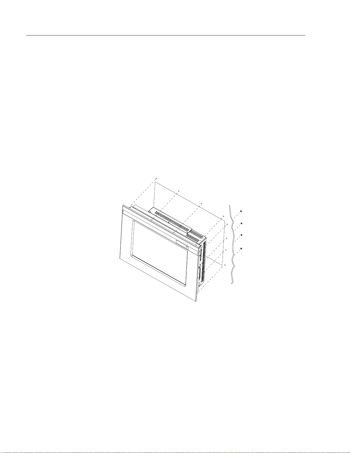
Panel Mounting
When properly installed, the 6185-E Flat Panel Monitor is designed to
provide p rotection agai nst water a nd dust to NEM A 4 and NEMA 12
standards.
No slides or shelves are required because the 6185-E Flat Panel Monitor
is designed to be supported by the panels in which it is installed.
Figure 1
Generic Panel Mount Diagram
Publication 6185-5.2
Page 7
Industrial 20.1" Flat Panel Monitor 7
Panel Mounting Guidelines
Observe the following precautions befor e installing the unit in a panel:
Confirm that there is ad eq uate spac e behind the p anel. Rememb er to
•
allow extra space (0.5 in. or 12.7 mm behind and on each side) for air
circulation. A cabinet with a minimum depth of 5.12 in. (130 mm) is
sufficient.
Take precautio ns so tha t meta l c utti ngs do not enter any c ompone nts
•
that are alrea dy installed in the panel.
Supporting panels should be at least 14 gauge to ensure proper
•
sealing against water and dust and to provide proper support. The
mounting hardware supplied accommodates panels up to 0. 25 in.
(6.35 mm) thick.
Note:
Supporting panels must be cut and drilled to
specifications prior to installation.
ATTENTION: Failure to follow these warnings may
result in personal injury or damage to the panel
components.
Publication 6185-5.2
Page 8
8 Industrial 20.1" Flat Panel Monitor
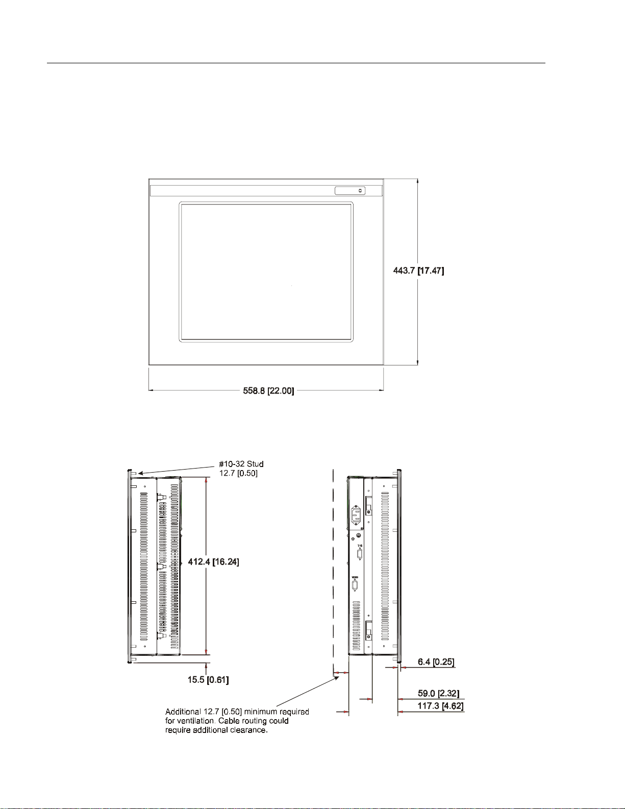
Dimensions
This section provides diagrams you need to follow to install the unit.
Figure 2
Dimensions ( Front Vie w)
Figure 3
Dimensions (Side View)
Publication 6185-5.2
Page 9
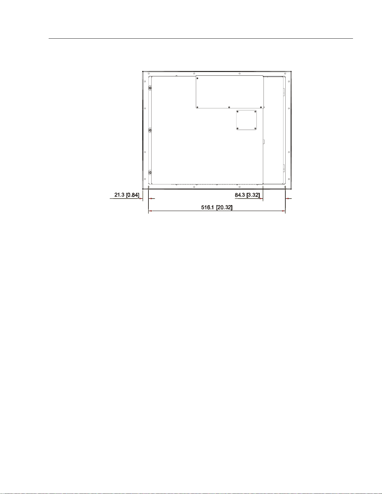
Figure 4
Dimensions (Back View)
Industrial 20.1" Flat Panel Monitor 9
Publication 6185-5.2
Page 10
10 Industrial 20.1" Flat Panel Monitor
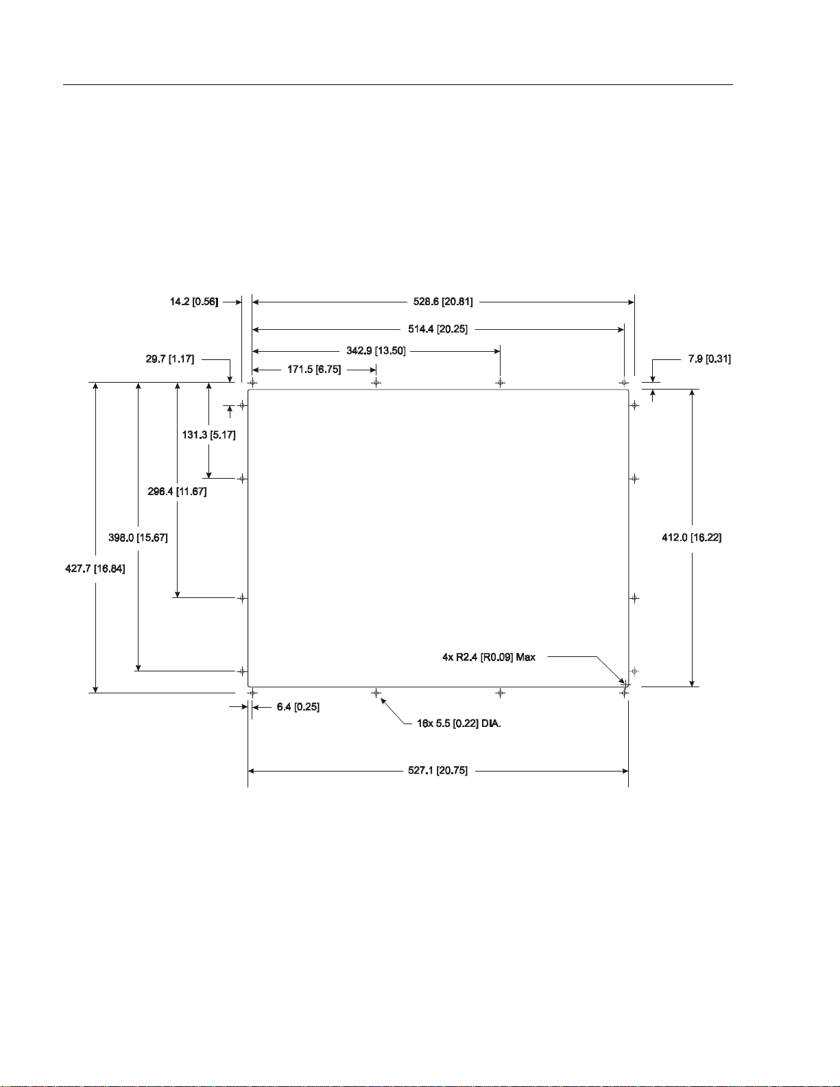
Panel Mounting Procedure
1. Cut and drill the panel (refer to following figure). Units are in mm
[inches].
Note:
Figure 5
Panel Mounting Cutout
Use #10-32 or M5 self-locking nuts for mounting.
Publication 6185-5.2
2. If access to the side of the monitor is not available following
installation, attach the power and video cables to the s ide of the
monitor at this time.
3. Install the monitor in the prepared cutout. Refer to the figure on this
page.
4. Install lock nuts and washers, supplied with the monitor, behind the
holes running a long the sides and top/bottom of the cutout in the
panel.
Page 11

Industrial 20.1" Flat Panel Monitor 11
5. Tighten all mounting bolts evenly to a torque of 24 inch-pounds.
ATTENTION: Mounting nuts must be tightened to a
torque of 24 inch-pounds to provide panel seal and avoid
potential damage. Rockwell Automation assumes no
responsibility for water or chemical damage to the
monitor or other equipment within the enclosure due to
improper installation.
Publication 6185-5.2
Page 12

12 Industrial 20.1" Flat Panel Monitor
Connecting the 6185-E Flat Panel Monitor
The side panel of the 6185-E Flat Panel Monit or has connectors for
attaching cables to accomplish the following:
Connecting to a host video source (HD-15 VGA connector)
•
Connecting to a host t ouchscreen control port (DB-9 connector)
•
(optional)
Connecting to AC power (IEC connect or) or DC power (terminal
•
block)
Note:
Some connectors on your monitor may differ from the
following figure.
The following figure illustrates the standard configuration for the 6185-E
Flat Panel Monitor.
Figure 6
Side Panel
Publication 6185-5.2
Page 13

Industrial 20.1" Flat Panel Monitor 13
Connecting the Video Source
The video connection to the host is made through a HD-15 (female)
connector located on the side panel.
Note:
For more information on using an HD-15 video ca ble to
connect to the host computer, refer to Appendix B
(Page 30).
To establish a signal using the HD-15 connector:
1. Obtain a shielded, properly terminated video cable of length as shor t
as possible. Longer cables (up to approximat ely 50 feet in some
cases) may be used, provided they are properly constructed. Your
package may include a six-foot video cable, if specified.
2. Connect one end of the cable to the female HD-15 video input
connector on the side panel of the monitor.
3. Conn e c t the other en d to th e ou tput of any IBM-co mp atible VGA
ada pter or other vide o generator.
Note:
You may connect the monitor to video genera tors that
do not conform to VGA standards. The main
requirement is that the gener a tor provide analog RGB
video signals (0.714V above reference black into 75
ohms) and separate horizontal and vertical sync signals.
Connecting the Touchscreen Interface
The serial touc hscreen interfa ce connection to th e host is made through
an RS-232 DB-9 (female) connector located on the side panel.
The optional touchscreen provides a high-resolution touc h input system.
Driver software included with the package allows the touchscreen to
function with many popular DOS and Windows
applications as a pointing device (mouse).
Note:
Refer to the manual included with the touchscreen option
and Appendix A of this manual (page 27) for a dditional
details on the installation and operation of the touchscreen.
To connect the touchscreen:
1. For units with the touchscreen option, make sure you have one of the
opti onal serial c ables.
2. Connect one end of the touchscreen serial cable to the T/S port
connector on the side of the monitor.
®
-based industrial
Publication 6185-5.2
Page 14

14 Industrial 20.1" Flat Panel Monitor
3. Conn e c t the other en d to any commu nicat ions p ort on t he host
computer.
4. Tighten the captive screws on the cable connector to secure it.
Connecting AC Power
The 6185-E Flat Panel Monitor requires a single pha se power supply
providing 85 to 264V AC at 47 to 70 Hz. Power must be available at a
grounded three-pi n outlet locate d nearby. Wh en e ver p ossib le, co nnect
the monitor to the same AC source that supplies the computer.
To connect AC power to the monitor:
1. Turn off the mai n switch or breaker.
2. Use the ground terminal of the monitor (below the power connector)
to est ablish a cha ssis- to-earth ground conn e c tion. Secure one e nd of
a ground strap to the ground terminal. Conn ect the other end of the
ground strap to a good earth ground.
The ground terminal is an M5 screw.
A TTENTION: Chassis ground must be connected for
safe operation of the monitor. The AC receptacle on the
monitor is a 3-wire type with chassis ground pin, and the
mating AC cord supplied is a 3-wire type, designed for
connection to a grounded 3-pin AC outlet. However, a
properly ground AC ou tlet is not always avai lable, and
grounding using a 3-wire cord can easily be defeated. If
you fail to ground the monitor proper ly, the setup may
resu lt in p ersona l injury from e lectric al shock or damage
to the equipment.
3. Connec t the socket end of the AC power cord to the mat ing
connector on the rear pa nel of the monitor. Position the power cord
retaining clip attached to the rear panel c onnector over the cord’s
socket to secure it in place.
4. Connect the plug end of the AC power cord to the main outlet.
5. Restore AC power to the outlet.
Publication 6185-5.2
Page 15

Industrial 20.1" Flat Panel Monitor 15
Connecting DC Power
The 6185-E Flat Panel Monitor requires a DC power supply providing
18 to 32V DC.
To connect DC power to the monitor:
1. Turn off the mai n switch or breaker.
2. Use the ground terminal of the monitor (below the power connector)
to est ablish a cha ssis- to-earth ground conn e c tion. Secure one e nd of
a ground strap to the ground terminal. Conn ect the other end of the
ground strap to a good earth ground.
The ground terminal is an M5 screw.
A TTENTION: Chassis ground must be connected for
saf e opera tion of the monitor. T he D C scr ew term inals on
the monitor have a chassis ground pin. However, some
DC s ources may not provide a proper ground path. If you
fail t o ground the monitor prop erly, the s etup ma y result
in personal injury from electrical shock or damage to the
equipment.
3. Connect the +VDC wire to the “+V” screw terminal. Connect the VDC wire to the “-V” screw terminal. Connect the power source
ground wire to the GND screw terminal. Tighten down the screw
terminals.
4. Restore DC power.
Publication 6185-5.2
Page 16

16 Industrial 20.1" Flat Panel Monitor
Initial Video Setup
The 6185-E Flat Panel Monitor is configured at the fa ctory, but typically
requires i nitial a djustme n ts to ens ure the best s c reen image. Rockwell
Automation prov ides th e F lat P anel Monitor Adjustment Ut ility with
each flat panel monitor to assist you in adjusting the monitor settings.
Important:
Fla t panel monitors ar e f ixed r esolution devic es and work
best when set at their native r esolution. If you switch the
resolution of this monitor from 1280 x 1024 resolution, the
disp lay ma y look d istorted.
Common Flat Panel Video Adjustments
The 6185-E Flat Panel Monitor provides controls to adjust the f ollowing
aspects of the monitor video display:
Horizontal and vertical position
•
Horizontal size of the display
•
Clock phase
•
Brig htness and contrast
•
It is important that you make initial adjustments to these settings to
ensure that the screen image on the flat panel monitor is set up correctly.
If th e h orizo ntal or vertical p ositi on of th e d isplay is not adjusted
correctly, one edge of the screen image extends beyond the side of the
monitor screen.
The horizontal size and clock phase adjustments are especially important
for flat panel monitors. If the horizontal size setting is not properly
adjusted, t h e scr een ima g e co ntains vertica l sha d ed ba rs. If the clock
phase setting is not properly adjusted, the screen image is “jittery.”
Figure 7
Monitor Video Adjustments
Publication 6185-5.2
Page 17

Industrial 20.1" Flat Panel Monitor 17
You may a lso need to adjust th e b rig htness or cont ras t of the sc reen
image based on the conditions of the location in which the monitor is
installed.
Adjusting Settings
Use these instructions to adjust the video settings to achieve the best
screen image.
Note:
For more inf ormation on the location and op eration of the
controls on the monitor, refer to Page 19.
Step 1 - Start the Adjustment Utility
1. Insert the diskette which was provi ded with the monitor in the floppy
drive of th e hos t co mputer
2. Start the Flat Panel Monitor Adjustment utility using the instructions
on the di sk ett e l ab el.
The utility displays an image on the screen to assist you in adjusting
the monitor settings.
Note:
The utility may take s everal seconds to display the
screen image.
Step 2 - Access the controls and use the auto-adjust feature
1. Loosen three of the four screws on the a ccess panel on the back of
the unit.
2. Slide the a ccess panel to reveal the control panel inside the unit.
3. Press the CLK- and CLK+ simultaneously to enable the auto-adjust
feature. The monitor will attempt to adjust the settings pr operly
based on the cur r ent signal. This process may take up to 20 seconds,
during which time the screen will be dark.
4. Do one of the following:
If the display looks acceptable, go to Step 6.
•
If the display does not look acceptable, r epeat the auto adjust
•
process two or three more times. If the display still does not look
acceptable, proceed to the next step.
Publication 6185-5.2
Page 18

18 Industrial 20.1" Flat Panel Monitor
Step 3 - Adjust the horizontal size
Use the H+ and H- controls to adjust the hor i z ontal size until the vertical
shaded bars disappear and the screen image fits the display precisely.
Note:
The v ertical size is f ixed and requires no user adjustment.
Step 4 - Adjust the horizontal and vertical position
1. Use the H LFT and H RT controls to adjust the horizontal screen
position.
2. Use the V UP a nd V DN controls t o adjust the vertical screen
position.
Step 5 - Adjust the clock phase
Use the CLK+ and CLK- contr ols to adjust the clock phase until the
screen image is s harp and there is no screen “j itter.” The change should
be most apparent in the vertical lines of the screen.
Step 6 - Saving Settings
Press SAVE to save the current settings for the current resolution.
Note:
Each resolution can have its own custom settings. You can
have different settings at 1280 x 1024, 1024 x 768, 800 x
600, 640 x 480, and 720 x 400 resolution.
Publication 6185-5.2
Page 19

Industrial 20.1" Flat Panel Monitor 19
Operating the 6185-E Flat Panel Monitor
This section describes how to operate the 6185-E Flat Panel Monitor.
You can adjust the monitor attributes several different ways:
Usi ng the optio nal luminance control on the front p anel
•
Using th e controls on t he rear pa ne l
•
Power Indicator
Two LED indicators are provided on the front panel to indicat e various
operating modes. The following table describes the functions assigned to
the LEDs:
Table A
Power Indicator LED
LED Color Indication
Gr een Normal operat ion
Amber
Power ON, loss of video sync or disconnected video
cable
Controls
The 6185-E Flat Panel Monitor is equipped with a cont r ol panel on the
back of the u nit, which allows you to a djust the screen display.
Figure 8
Controls on Back Panel
Note:
Do not adjust the s witches at the top of the control
panel.
Publication 6185-5.2
Page 20

20 Industrial 20.1" Flat Panel Monitor
Table B
Control Panel for Adjusting Monitor Settings
Abbreviation Control Name Control Function
CLK- Clock Left
CLK+ Clock Right Moves the signal sampling points to the right. Eliminates display
SAVE Save Saves the current settings for the current resolution.
CLEAR Clear Moves the last saved active setting to the current setting.
BKLGHT Backlight Turns the LED backlight ON and OFF.
TEST Test
V DN Vertical Down Moves the display down on the LED display.
V UP Vertical Up Moves the display up on the LED display.
BRT- Decrease Brightness
BRT+ Increase Brightness Increases brightness of the display. (Not used when front panel
H LFT Horizontal Left Moves the display left on t he LED display.
H RT Hori zontal Right Moves the display right on t he LED display.
H- Horizontal Reduce Reduces the horizontal display size. Synchronizes the sam pling
H+ Horizontal Increase Increases the horizontal display size. Synchronizes the sampling
Moves the signal sampling points to the left. Eliminates display jitter
and fuzziness. Change this setting after all other adjustments have
been made. Adjust setting until vertical lines are crisp.
jitter and fuzziness. Change this setting after all other adjustments
have been made. Adjust setting until vertical lines are cr isp.
Decreases bri ghtness of t he display. (Not us ed when f ront panel
luminance control installed.)
luminance control is installed.)
frequency with signal frequency.
frequency with signal frequency.
Publication 6185-5.2
Page 21

Industrial 20.1" Flat Panel Monitor 21
Interpreting the LEDs on the Control Board
The c ontrol board contains f ive LED s that are visible through wh e n you
remo ve the access pane l ( four red LEDs and on e green LED). If the
monitor is functioni n g properly, the green LE D (PWR ) and one red LE D
(L1) should be lit.
If more than one red LED is lit, then consult the following table to
interpret the sta tus LEDs. If you still cannot fix the pr oblem, contact
Technical Support for additional assistance.
Table C
Interpreting the Control Board Status LEDs
LED 1 LED 2 LED 3 LED 4 Stat us
X X Screen image control is out of range
(beyond range of Vertical Up).
X X No sync.
X X No vertical sync.
X X Unable to center screen.
X X Problem with Flash RAM.
X X Sync signal has changed.
Note:
This combi natio n f las hes bri efly
any time the screen resolut ion
changes. A constant blinking cycle of
this combination indicates an error
condition.
X X X Bad power.
X X X Invalid switch combination.
Publication 6185-5.2
Page 22

22 Industrial 20.1" Flat Panel Monitor
Dimmer Con trol
The 6185-E is equipped with proprietary display dimming circuitry that
all o ws full rang e control of image luminance from the fro nt panel. The
LEDs are present with or without the dimmer control, but the two
but tons that adju st the luminance of the dis play are opt ional.
Figure 9
Dimmer Control
Publication 6185-5.2
The control buttons adjust t he luminance of the image, w h ich is not the
same as the brightness setting. Luminance refers to the actual intensity
of the light emitted from the monitor. Brightness refers to the
appearance of the image displayed – a range between dark and dazzling.
The backlights are controll e d by the luminance co ntrol.
To adjust the luminance of the monitor:
Pr es s and hol d either one of the dimmer b uttons unti l the lumi nanc e is
adjusted as desired.
The left dimmer button reduces the luminance and the right button
•
increases it.
The green LED blinks fast when you first press the button and slows
•
down as you reach t he end of the ad just me nt ra nge.
When you release the dimmer button for three seconds, the amber
•
LED blinks twice to indicate that your changes ha ve been saved and
wi l l be used each time th e mon itor is powere d ON.
Page 23

Industrial 20.1" Flat Panel Monitor 23
To turn off the monitor without turning off the power:
1. Press and hold both buttons for 2 sec onds, until the monitor’s
backlight is turned OFF.
2. Press either button to turn the backlight back ON.
Table D
Interpreting the Dimmer LED
Green LED Amber LED Condition
On Off Normal Operation - The monitor is receiving a valid video signal.
Off On Signal Not Received - The m onitor is not receiving a valid video signal.
On (blinking
slowly)
On (blinking
fast then slow)
On
Off
Off Changing Dimmer Setting - When you are pressing one of the dimmer buttons,
On (blinking
slowly)
Backlight Off - The monitor is still ON but the backlight is powered OFF. Hold
down both buttons for 2 seconds to disable the backlight. Press either button to
enable the backlight.
the LED blinks fast and slows down as you reach the end of the possible dim mer
adjustments in that direction. The light stops blinking when you stop pressing
the button, and the amber LED blinks twice when the change has been saved.
Once a dimmer settin g has been saved, it will be used each time the monit or i s
powered O N.
Calibration Mode - The monitor has a calibration mode to compensate for
abnormal signal levels. Calibration mode is started by holding down both buttons
for 8 seconds. To turn off the calibration mode, hold down both buttons for 2
seconds until the amber light is turned OFF. The amber light will blink twice after
calibration mode to indicate that the calibration is complete.
If you need to adjust the cal ibra t ion mode, contact Rock well Autom ation. Thes e
instructions are provided only so you can get out of calibration mode if you get
into it accidentally.
Publication 6185-5.2
Page 24

24 Industrial 20.1" Flat Panel Monitor
Routine Maintenance
Cleaning
Occasionally clean the display panel and cabinet wit h a soft cloth
dampened (not soaked) with a mild (non-abrasive) glass cleaner. Keep
turning a fresh s ide of the cloth t owar d the screen surface to a void
scratching it with accumulated grit.
Note:
Special ca re shou ld be taken when cl eanin g a touc hscr een or
polycarbonate shield that is installed over the screen. Abrasive and
certain chemical cleaners can ea sily damage the surface. Never use
alcoholic or ammoniac cleaners.
The solvent should be applied only to the cloth, a nd not
directly on the monitor screen.
Do not use paper products as they may scr atch the surfac e.
To minimize the risk of abrasion, allow the scr een to
sta nd dr y.
Replacing a Line Cord
To avoid s hock and fire haza rds, the moni tor’s power cord should be
replaced if the insulation becomes broken or if it develops a loose
internal conne c tion.
Other Maintenance
Qualified service personnel should perform all maintenance, except for
the power cord replacement described above.
Publication 6185-5.2
Page 25

Industrial 20.1" Flat Panel Monitor 25
Troubleshooting
You can refer to this table to help identify the cause and offer a solution
to a problem. This table lists typical problems you may encounter.
Table E
Troubleshooting Table
Symptom Possible Problem Action
Front panel status LED does not come on. Power cord not connected. Open 6185-E and reconnect the power
No power av ail able at outl et . Test outl et by pl ug gi ng in a lamp or other
Power cord faulty. Replace power cord.
Monitor f aulty. Have moni t or serviced.
Screen is blank. Screen saver activated. Check the status LED using the table
Bright n ess c ontrol not proper l y ad jus ted. Turn brig ht n ess c ont r ol UP .
Video cable problem
Image is to o bright or whit e. Br ig ht ness contr ol n ot pr op er l y ad jus t ed. Turn bright n ess c ontrol DOW N .
No image vis i ble even when brightness
control is set full UP.
Image is di m, e ven wi th brightnes s and
contrast controls set full UP.
Image is not centered. Position controls are not properly
Image will not adjust. Video timing outsi d e of r ang e. Use the control panel to ad jus t th e C l ock
Image position changes are not saved. Position mode not saved correctly. Reposition the image using the rear
Image is not stable. Monitor is not synched to video source. Refer to installation instructions.
Vertical shaded bars on screen image. Horizontal size not properly adjusted. Adjust horizontal size settings (Page 20).
Monitor is out of ad jus t m ent or fault y. Have moni tor servic ed.
Video cable problem Check for pr oper installation of video
Fault in vid eo s our ce Test video source by connect in g t o
Fault in mon itor Have moni tor servic ed.
adjusted.
cord.
known good devic e.
provided on Page 23. Disable screen
saver by activating an input to the host
system.
Check for pr oper installation of video
cable(s). Refer to installation instructions.
Replace suspected faulty cable(s).
cable(s). Refer to installation instructions.
Replace suspected faulty cable(s).
another m onitor that is kn own to be
operational.
Reset the horizontal and vertical
positioning using the control panel
(Page 20). Also, check to ensure that
video s ource is operati n g wi thi n the
monitor’s range.
Setting (Page 20). Make sure timing is
within VESA.
accessible control panel, save the
chang es an d exi t .
Check for pr oper video cable installation.
Replace suspected faulty cable.
Check to ens ure that video s ource is
operating within the display’s range. Adjust
the Phase control (Page 20).
Publication 6185-5.2
Page 26

26 Industrial 20.1" Flat Panel Monitor
Symptom Possible Problem Action
Color(s) ar e missing. Video cable problem Check for proper video cable installation.
Fault in mon itor Have moni tor servic ed.
Screen jitter or noisy video. Monitor clock phase not properly
adjusted.
Video cable problem. Check for pr oper video cable installation.
El ectrical n oise in terference f rom n e a rb y
equipm ent.
Replace suspected faulty cable.
Adjust m onitor clock p h as e s ett in gs
(Page 20).
Replace suspected faulty cable.
Check for proper video cable routing an d
installation. Reroute cables or replace
suspected faulty cables.
Check hos t an d m onitor groun di ng .
Publication 6185-5.2
Page 27

Industrial 20.1" Flat Panel Monitor 27
$
$SSHQGL[ $
SSHQGL[ $
,QWHUIDFH
,QWHUIDFH
7
7RX
RXF
FKVF
KVFU
UHHQ 6
HHQ 6H
HULDO
ULDO
Description
Setting Up the Touchscreen Interface
All touch controllers are configured by default to provide serial
communications at 9600 baud, 8 data bits, 1 stop bit, no parity.
For Allen- Bra dley monitors equipped with touchscreens, a serial
communications cable is requ ir ed. A suit able cable can be obta i n ed fr o m
Rockwell Automation or you can create one.
The cable provides a communications channel between the touchscreen
controller, which is mounted inside the monitor, and an RS-232-C serial
port on the host computer. Because the touch controller obtains power
from the monitor's power supply, no external touch power connections
are necessary.
Software supplied with the t ouchscreen must be loa ded on the host
computer to ha ndle communications with the touch controller over the
channel.
Because t he touchscreen emu l ates a mouse, there may be c ompa tibili ty
issues involving how the touchscreen emulates mouse buttons, especially
multiple buttons. For a complete discussion of these issues and how to
troubleshoot them, refer to the touc hscreen documentation.
This section describes how to set up the touchscreen system using the
6185-E Flat Panel Monitor. Setup involves the following:
• Enabling the touchscreen interface
• Installing the s oftware on the host computer that will handle
communications with the touchscreen contr oller
• Performing a calibrati o n
Enabl ing th e To uchscreen Interf a c e
The 6185-E Flat Panel Monitor provides a fema le DB-9 connector on the
side panel. This connector provides the s erial interface for the touch
controller.
Publication 6185-5.2
Page 28

28 Industrial 20.1" Flat Panel Monitor
Interconnecting wiring to the host serial port connection is shown in the
following table.
Table F
Touchscreen Interface
Monitor
(DCE Device) Host (DTE Device)
DB-9 (Female) Signal Description DB-9 (Male) DB-25 (Male)
1 Not Connected (DCD) 1 8
2 Transmit Data (TXD) 2 3
3 Receive Data (RXD) 3 2
4 Data Terminal Ready ( DTR) 4 20
5 Common Signal Return (SG) 5 7
6 Not Conn ected (DSR) 6 6
7 Request To Send (RTS) 7 4
8 Clear To Send (CTS) 8 5
9 Not Conn ected 9 22
Installing the Touchscreen Driver Software
To install the touchscreen driver software correctly, obtain the following
information a bout the host hardware:
The COM por t in use for the touchscreen. Ensure that the RS-232
•
cable is properly installed between the monitor port and the host’s
COM port.
The baud rate at wh ich the controller is oper ating. Yo u will need to
•
match the ba ud rate at the COM port. The controller baud rate is
factory set a t 9600.
Note:
Once you have obtained this information, install the software using the
installation disks found in the touchscreen a ccessory package.
If you are using older touchscreen software, you may be
prompted for the type of touchscreen controller being used.
The 6185-E uses the following controllers:
Resistive: Elo TouchSystems model E271-2210.
•
Ca paciti ve: MicroTouch model SMT-3.
•
Publication 6185-5.2
Page 29

Industrial 20.1" Flat Panel Monitor 29
Performing a Calibration
Note:
After installing the driver software, follow the instructions in the
touchscreen documentation.
Following installation of the touchscreen software and calibration, the
touchscreen is ready to use.
Before installation, you may want to check the touchscreen
manufacturer’s site on the World Wide Web for the latest
sof twa re drivers. Enter these ad d resses in y o ur I n ternet
browser:
www.elotouch.com for resistive touchscreens
•
www. micr otou ch.co m for capacitiv e touchscreens.
•
Publication 6185-5.2
Page 30

30 Industrial 20.1" Flat Panel Monitor
$
$SSHQGL[ %
SSHQGL[ %
You use an HD-15 video cable equipped with a conventional HD-15
connector at each end to connect the 6185-E Flat Panel Monitor to the
host computer.
+
+'
' 9
9LGHR &
LGHR &D
DEOH
EOH
Note:
Figure 10
HD-15 Video Connector
The following table provides the pin numbers and corresponding pin
assignments for the HD-15 video connect or with the DDC2B ca pability:
Table G
Standard HD-15 Video Cable
Monitor HD-15
(Female)
The following figur e is the view looking into the p in end of
the male c onnector or solder term end of the female
connector.
Signal Description
1Red Video 1
2 Green Video 2
3Blue Video 3
4Not Used 4
5Return 5
6 Red Video Ground 6
7 Green Video Ground 7
8 Blue Video Ground 8
9Not Used 9
10 Sync Ground 10
11 Not Used 11
12 Bi-Directional Data 12
13 Horizontal Sync 13
14 Vertical Sync (VCLK) 14
15 Data Clock (SCL) 15
Host
HD-15 (Male)
Publication 6185-5.2
Page 31

Specifications
Industrial 20.1" Flat Panel Monitor 31
Display
Type Active Mat rix Color Thin Film Transistor (TFT) LCD
Backlight
Type
Life Expectancy
Field Replaceable
Nominal Displa y Area
Horizontal
Vertical
Resolution 1280x1024 pixels, full color
Viewing Angle
Horizontal (typical)
Vertical (typical)
Luminance (typica l) 130 nit, 38 fL
Contrast Ratio (typical) 100:1
CIE coordinates
White x=0.291, y=0.338
Response Time 130 msec (typical)
Cold Cathode Tube (CCT)
17,500 h ours (typic al)
No
15.7in. (399mm)
12.6in. (319mm)
+/-80deg.
+/-80deg.
Video
Suppor t ed Standards 720x40 0 at 70 Hz (VGA text)
640x48 0 at 60Hz and 75Hz
800x60 0 at 60Hz and 75Hz
1024x7 68 at 6 0H z and 75Hz
1280x1 02 4 at 60Hz and 75H z (native)
Video Input Signal RGB analog (white level = 0.714V above ref. Black,
Sync Input Si gn als H and V separate (TTL levels, p osit ive or negati ve)
Inpu t Connection HD-15
Controls and Indicators
Front Panel Luminance (optional)
Back Pan el Horizontal Size, Ver tical Posit i on, H orizontal P osi tion,
Operator Input
Electrical
Line Volt age 85 to 264VA C, or 18 t o 32 VD C
Line Frequency 47-70Hz or DC
Ground Leakage 1.0 uA max at 1.5KVDC
Power Consumption 85W max, 100 VA
into 75 Ohms
Contrast, Brightness, Clock Phase, Backlight
Touchscreen Option - Resistive or capacitive
touchscreen, with serial controller and DOS and
Windows dr i v er s
Publication 6185-5.2
Page 32

32 Industrial 20.1" Flat Panel Monitor
Environmental
Pane l Rating NEMA 4/12 (built to IP65 sta ndards), NEMA 4X
Operating Temperature 0C to 50C
Storag e T emperatur e -20C to 60C
Relati ve Hu midity 10% to 85% n on-condensing
Operating Altitude Sea level to 10,000 ft (3048m)
Non-Operating Altitude Sea level to 25,000 ft (7620m)
Operating Electrostatic
Discharge
Non-Operating Electrostatic
Discharge
Opera ting Shock 10g (1/2 sine, 11msec)
Non-Operating Shock 30g (1/2 sine, 11msec)
Operating Vibration 0.006in. p-p, 10-57Hz,
Non-Operating Vibration 0.006in. p-p, 10-57Hz,
Optional
8.0K VDC (IE C 801-2, level 3)
20.0K VDC
1.0g peak, 57-640Hz si ne
1.0g peak 57-640Hz sine
Physical
Panel Bezel Dimensions
(W x H x D)
Overall Dimensions (from rear
surface of front panel to bac k)
Net Weight 24.0lb (11.0kg)
Certifications
22.0in. x 17 . 5 in. x 0. 25 in . (5 5 9m m x 444mm x 6mm)
20.3in. x 16 . 2 in. x 4. 6i n. ( 51 6 m m x 41 2 m m x 11 7m m)
UL 1950 Recognized Component,
C-UL 950 R ec og ni z ed C om p onent,
CE (89/336/EEC and 73/23/EEC),
FCC Class A
Publication 6185-5.2
Page 33

IBM is a registe red trademark of In ternational Busin e ss Machines Corporation.
VGA is a trademar k of Internation al Business Machines Corporation.
PC AT is a trademark of Internat ional Business Machines Corpo ration.
Microsoft is a regist ered tradem ark of Microsoft Corpor ation.
Microsoft Windows is a trademar k of Microsof t Corporation .
Rockwell A utomation h el ps i ts custom ers receive a superior return on their investment by bringing
together leading brands in industri al aut omation, creating a broad spect rum of easy-t o-i ntegrate
products. T hese are supported by local technical resources availabl e worldwide, a gl obal network of
system s olutions provid ers, and the advanced technology resources of Rockwell.
Worldwide representation.
Argentina • Australia • Austria • Bahrain • Belgium • Bolivia • Brazil • Bulgaria • Canada • Chile • China, People’s Republic of • Colombia • Costa Rica • Croatia • Cyprus • Czech
Republic • Denmark • Dominican Republic • Ecuador • Egypt • El Salvador • Finland • France • Germany • Ghana • Greece • Guatemala • Honduras • Hong Kong • Hungary
Iceland • India • Indonesia • Iran • Ireland • Israel • Italy • Jamaica • Japan • Jordan • Korea • Kuwait • Lebanon • Macau • Malaysia • Malta • Mexico • Morocco • The Netherlands
New Zealand • Nigeria • Norway • Oman • Pakistan • Panama • Peru • Philippines • Poland • Portugal • Puerto Rico • Qatar • Romania • Russia • Saudi Arabia • Singapore
Slovakia • Slovenia • South Africa, Republic of • Spain • Sweden • Switzerland • Taiwan • Thailand • Trinidad • Tunisia • Turkey • United Arab Emirates • United Kingdom • United
States • Uruguay • Venezuela
Rockwell Automation Headquarters, 1201 South Second Street, Milwaukee, WI 53204-2496 USA, Tel: (1) 414 382-2000, Fax: (1) 414 382-4444
Rockwell Automation European Headquarters, Avenue Hermann Debroux, 46 1160 Brussels, Belgium, Tel: (32) 2 663 06 00, Fax: (32) 2 663 06 40
Rockwell Automation Asia Pacific Headquarters, 27/F Citicorp Centre, 18 Whitfield Road, Causeway Bay, Hong Kong, Tel: (852) 2887 4788, Fax: (852) 2508 1846
World Wide Web: http://www.ab.com
998042-010
Publication 6185-5.2
Copyright 1998 Rockwell Automation Corporation. All rights reserved. Printed in USA.
•
•
•
 Loading...