

Page 1

Installation Instructions
RAC6182 Industrial Computer
English......................................................................................................... Page 2
Station industrielle RAC6182
Français ..................................................................................................... Page 17
Industriecomputer RAC6182
Deutsch...................................................................................................... Seite 32
Computadora industrial RAC6182
Español................................................................................................... Página 47
Computer industriale RAC6182
Italiano.................................................................................................... Pagina 62
Computador Industrial RAC6182
Português................................................................................................ Página 77
Page 2

Installation Instructions
RAC6182 Industrial Computer
Chapter Objective
This chapter describes installation of the RAC6182 Industrial Computer for the
Windows CE Operating System including how to install the RAC6182 in a panel
using mounting clips.
European Union Compliance
The RAC6182 Industrial Computer meets the European Union Directive
requirements when installed within the European Union or EEA regions and has
the CE mark. A copy of the Declaration of Conformity is available at the
Rockwell Automation / Allen-Bradley Internet site: www.ab.com
ATTENTION: The RAC6182 Industrial Computer is intended
to operate in an industrial or control room environment, which
utilizes some form of power isolation from the public low
voltage mains. Some configurations may not comply with the
EN 61000-3-2 Harmonic Emissions standard as specified by the
EMC Directive of the European Union. Obtain permission
from the local power authority before connecting any
configuration that draws more than 75 watts of AC power
directly from the public mains.
Page 3

RAC6182 Industrial Computer 3
Environmental Considerations
Mount the RAC6182 Computer in a panel or enclosure to protect the internal
circuitry. Versions with a gasketed bezel meet NEMA Type 1, 12, 13 and 4X
(Indoor use) and IEC 1P54, 1P65 only when properly mounted in a panel or
enclosure having an equivalent rating. The non-display version does not have a
gasket and has a NEMA Type 1 and IEC 1P2X rating.
Allow enough room within the enclosure for adequate ventilation. Also consider
heat produced by other devices in the enclosure. The ambient temperature around
the RAC6182 Computer must be maintained between 0
F). The RAC6182 Computer is intended for use in Pollution Degree 2
environments.
Make sure you provide provisions for accessing the top, bottom, and side panels
of the RAC6182 Computer to install/remove components and to access the
connectors.
o
and 50 oC (32 o to 122 o
Publication 6182-IN001D-MU-P
Page 4

4 RAC6182 Industrial Computer
Hazardous Location Considerations
This equipment is suitable for use in Class I, Division 2, Groups A, B, C, D or
non-hazardous locations only. The following WARNING statement applies to use
in hazardous locations.
ATTENTION: EXPLOSION HAZARD.
• Substitution of components may impair suitability for Class
I, Division 2.
• Do not replace components or disconnect equipment unless
power has been switched off or the area is known to be nonhazardous.
• Do not connect or disconnect components unless power has
been switched off or the area is known to be non-hazardous.
• All wiring must comply with N.E.C. article 501-4(b).
Publication 6182-IN001D-MU-P
Page 5
RAC6182 Industrial Computer 5
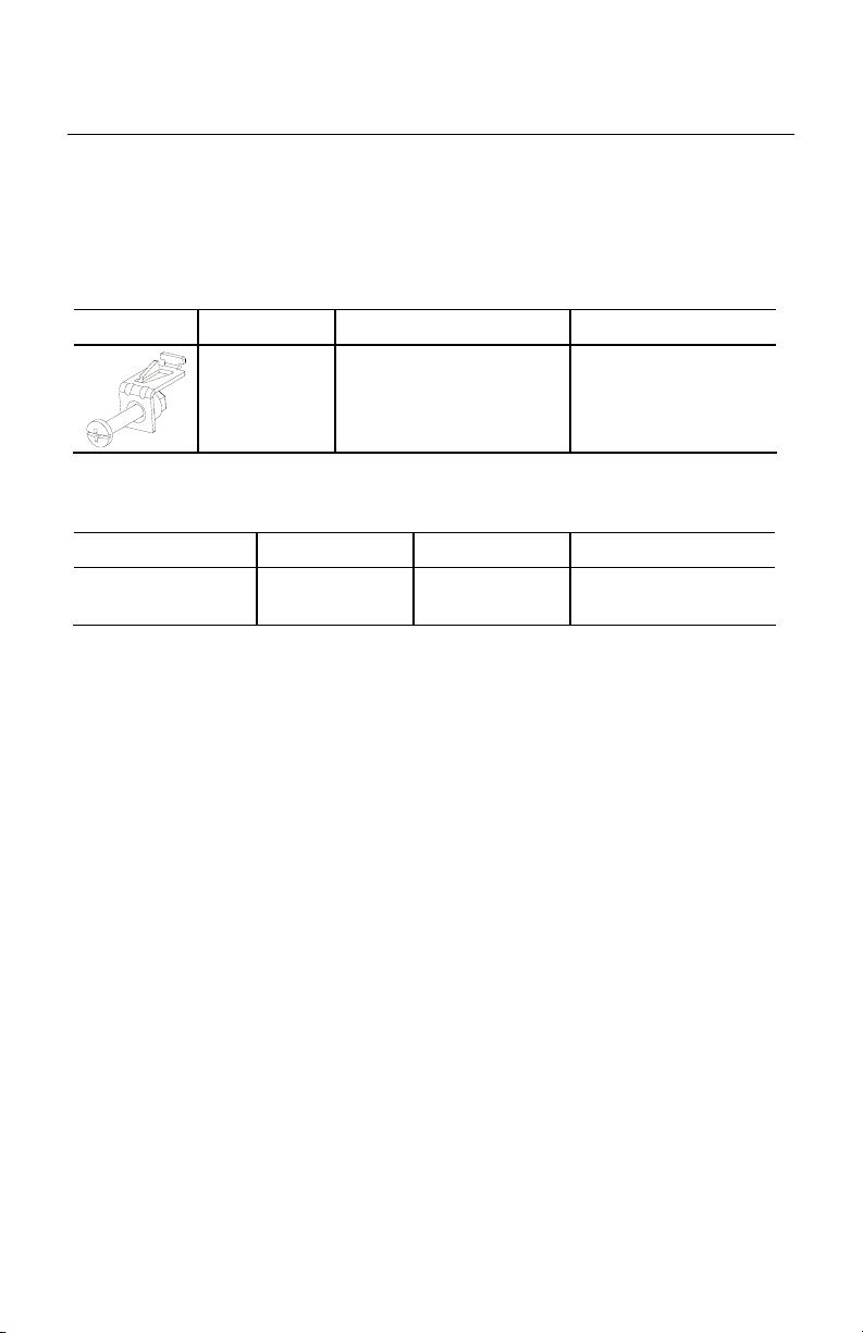
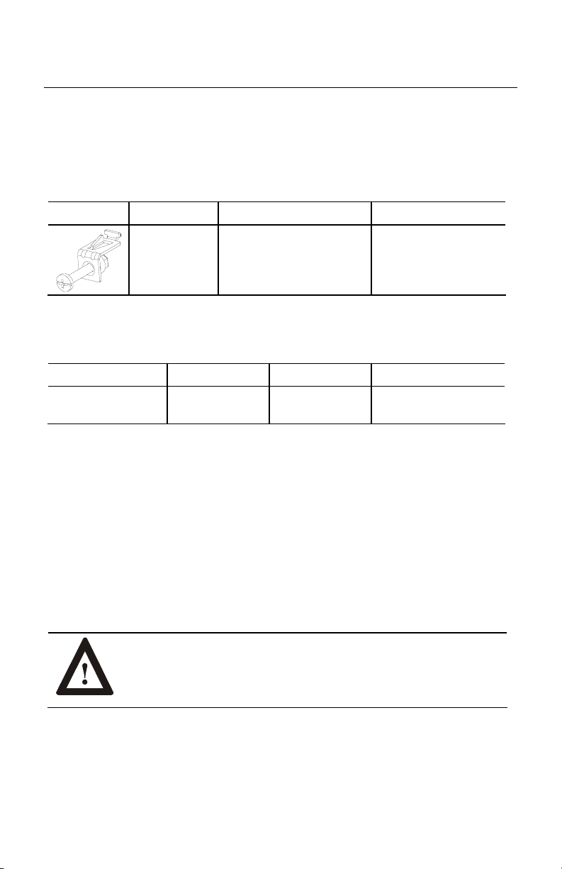
Mounting Hardware
Versions of the RAC6182 Computer with a display are shipped with the following
mounting hardware.
Item Description Quantity Use For
Mounting
Clips
4 Clips Panel or enclosure
mounting
The following replacement clips can be ordered from Rockwell Automation:
Part Number Description Quantity Use For
6189-2MTGKIT Mounting clips Package of 4
clips
Replacement item
Tools Required
In addition to the tools required to make the cutout, you will need a #2 Phillipshead screwdriver and a torque wrench.
Publication 6182-IN001D-MU-P
Page 6
6 RAC6182 Industrial Computer
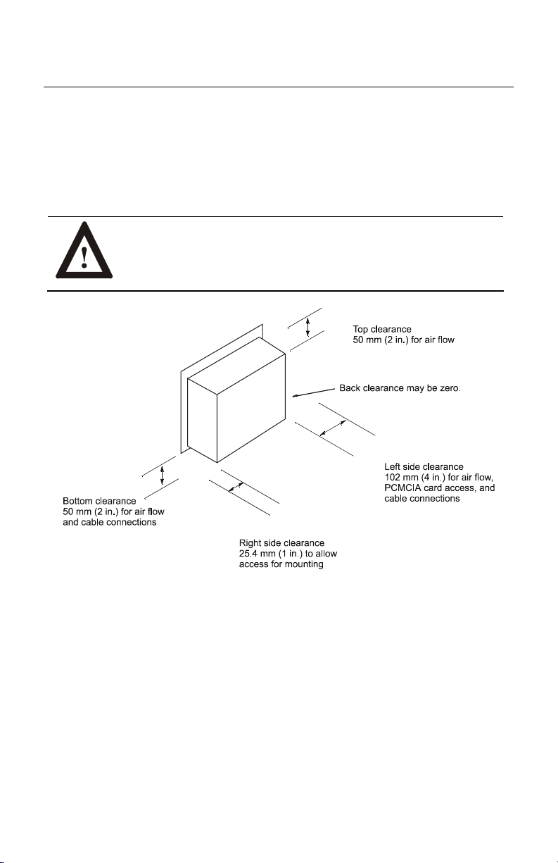
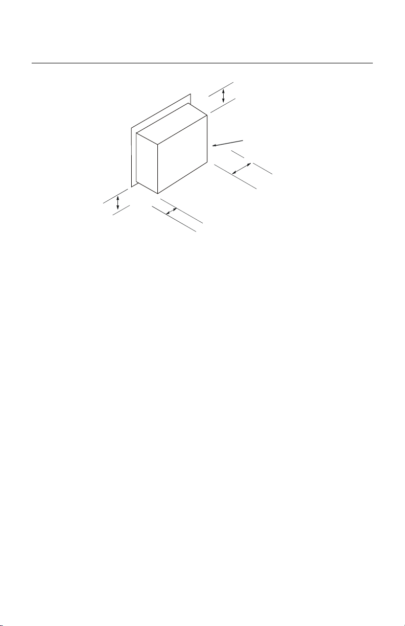
Mounting Clearances
Allow adequate space for mounting, air flow, and maintenance. The figure below
shows recommended minimum clearances to other components within the rack or
enclosure.
ATTENTION: The RAC6182 Computer should not be operated
within a confined space of the dimensions shown below unless
adequate ventilation or other cooling methods are used to lower
the air temperature within the enclosure.
Publication 6182-IN001D-MU-P
Page 7

RAC6182 Industrial Computer 7
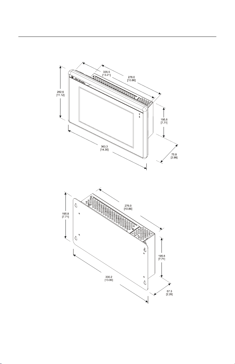
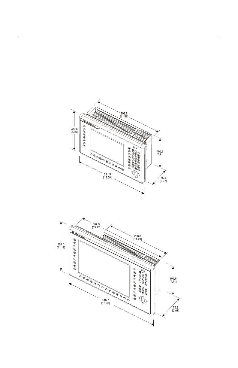
Mounting Dimensions
Note:
Measurements in these figures are expressed in millimeters
[inches].
7.7 in. Version with Keypad
12.1 in. Version with Keypad
Publication 6182-IN001D-MU-P
Page 8
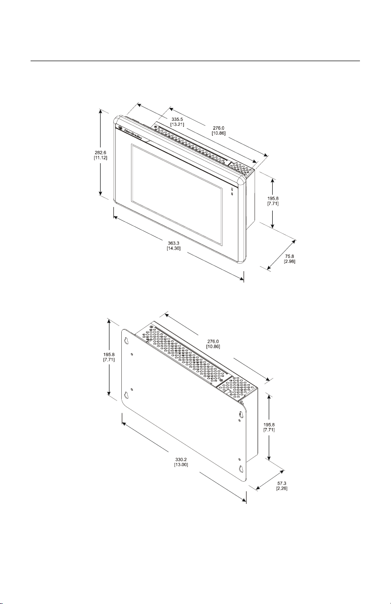
8 RAC6182 Industrial Computer
12.1 in. Version with No Keypad
Non-Display Version
Publication 6182-IN001D-MU-P
Page 9
RAC6182 Industrial Computer 9
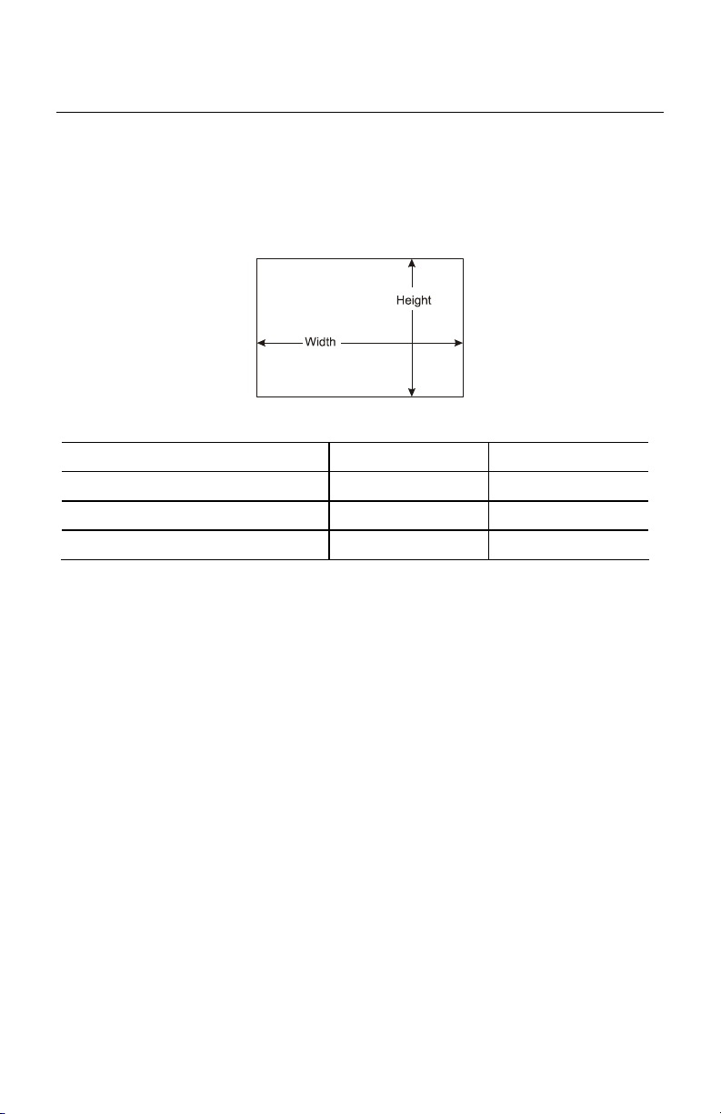
Mounting Cutouts
The following figure provides the dimensions for making the panel or enclosure
cutout for the RAC6182 Computer.
Display Size Height Width
7.7 in. version with keypad 197.8 [7.79] 295.8 [11.65]
12.1 in. version with no keypad 256.8 [10.11] 337.6 [13.29]
12.1 in. version with keypad 256.8 [10.11] 389.9 [15.35]
Publication 6182-IN001D-MU-P
Page 10
10 RAC6182 Industrial Computer
Panel Mounting
To install the RAC6182 Computer in a panel:
ATTENTION: Disconnect all electrical power from the panel
before making cutout.
Make sure the area around the panel cutout is clear.
Take precautions so that metal cuttings do not enter any
components that are already installed in the panel.
Failure to follow these warnings may result in personal injury
or damage to the panel components.
1. Cut an opening in the panel using the panel cutout dimensions provided on
Page 9.
2. Make sure the RAC6182 Computer sealing gasket is properly positioned on
the terminal. This gasket forms a compression type seal. Do not use sealing
compounds.
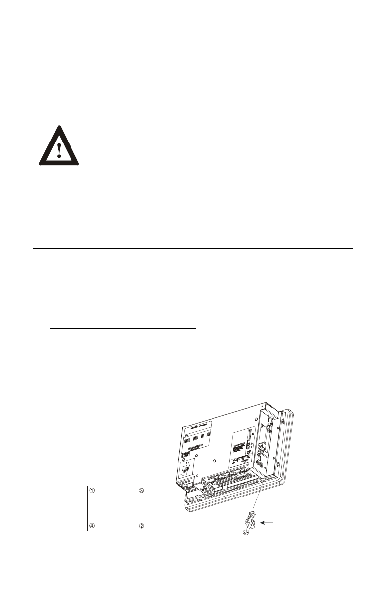
3. Place the RAC6182 Computer in the panel cutout.
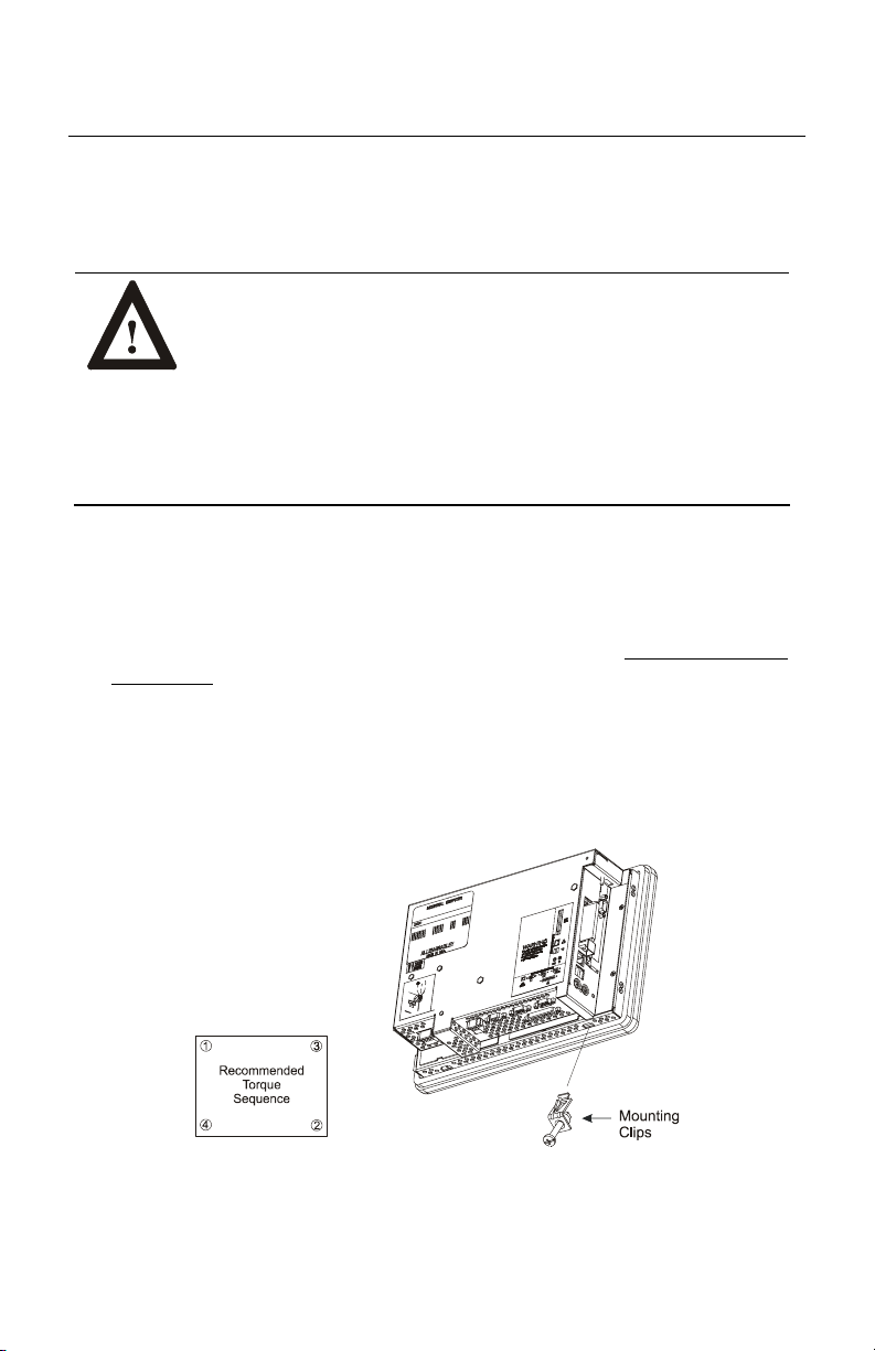
4. Install the mounting clips. The mounting clips slide into the slots on the top
and bottom of the RAC6182 Computer.
Publication 6182-IN001D-MU-P
Page 11
RAC6182 Industrial Computer 11
5. Gradually tighten the clips one at a time around the bezel using the specified
sequence. Repeat this process at least three times
until the clips are hand tight
and the gasket is compressed uniformly against the panel.
6. Tighten mounting clips to a torque of 10 inch–pounds (1.1 N•m) in the
sequence shown above. Do not over–tighten.
ATTENTION: Tighten mounting clips to a torque of 10 inch–
pounds (1.1 N•m) to provide a proper seal and prevent damage
to the RAC6182 Computer. Rockwell Automation assumes no
responsibility for water or chemical damage to the terminal or
other equipment within the enclosure because of improper
installation.
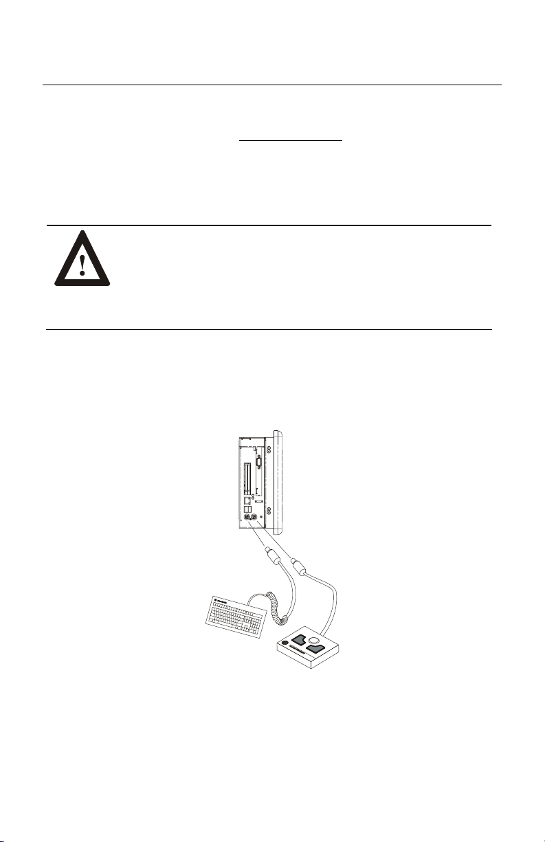
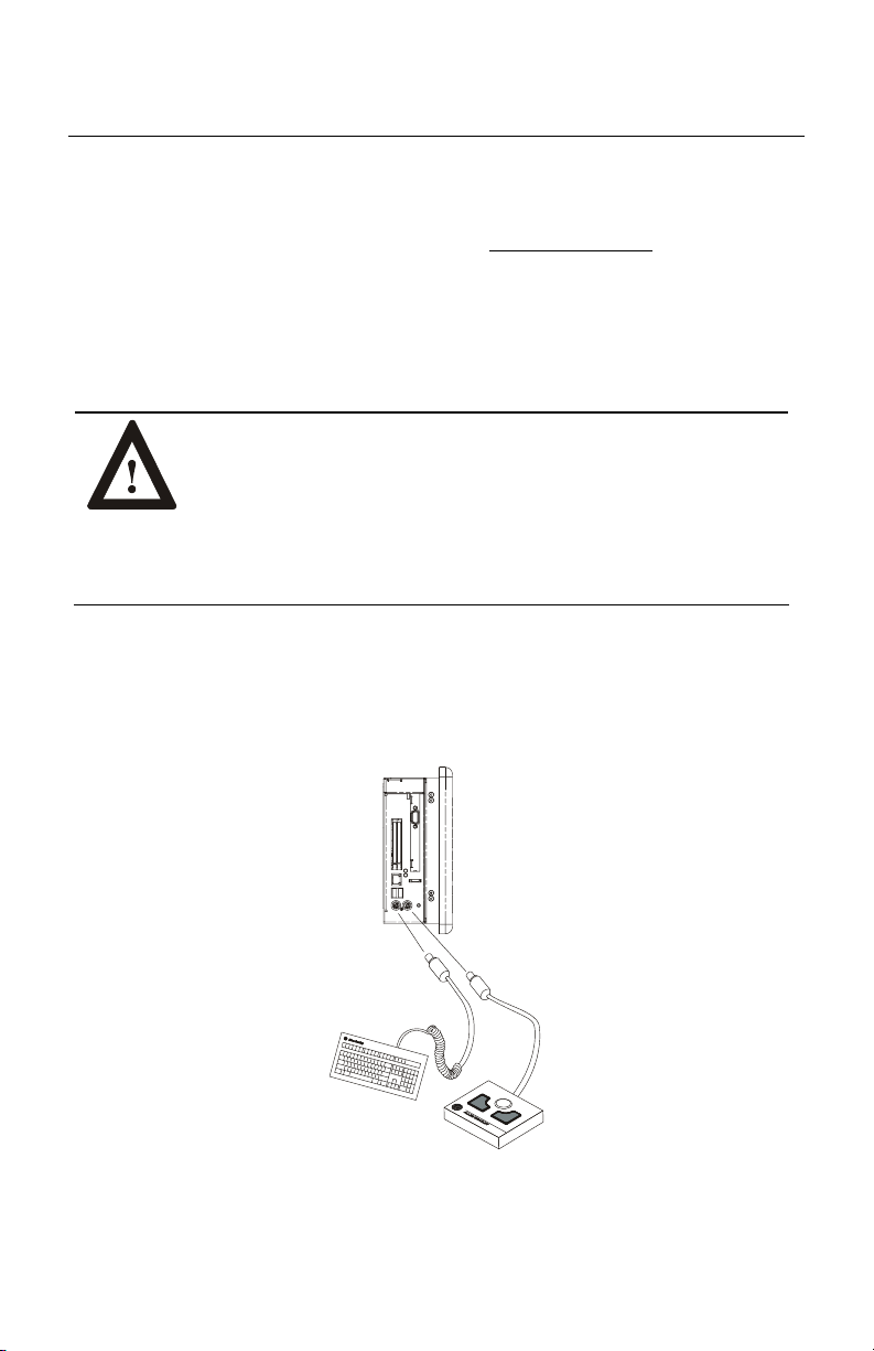
Connecting a Mouse & Keyboard (Side Panel)
The mouse and keyboard plug into the side panel mouse and keyboard ports as
shown below.
Publication 6182-IN001D-MU-P
Page 12
12 RAC6182 Industrial Computer
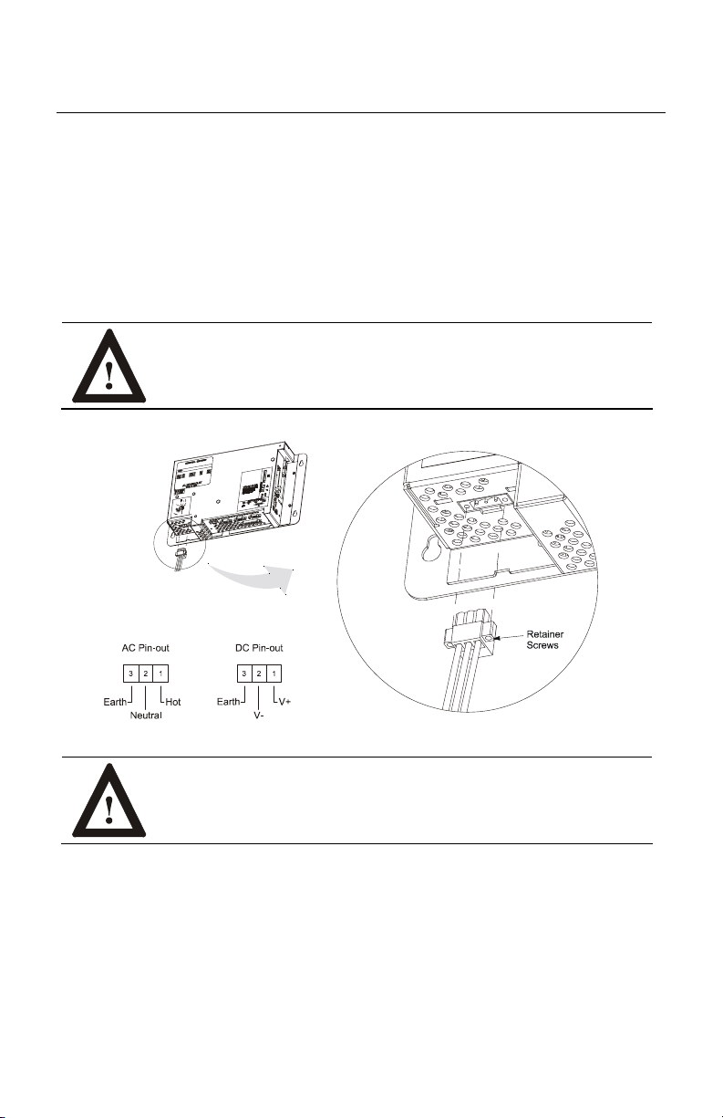
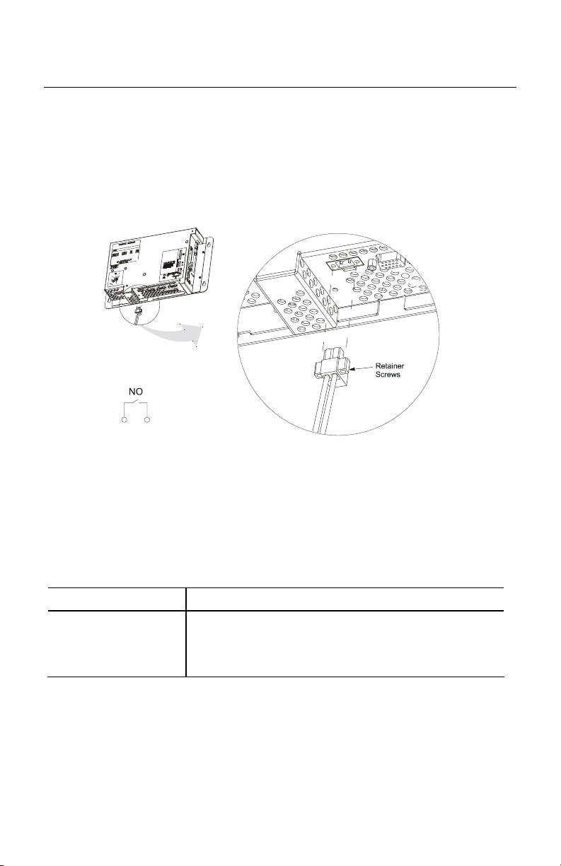
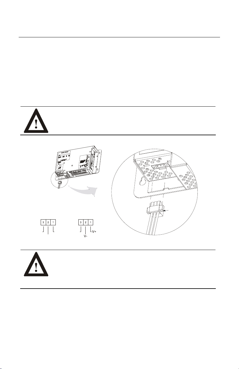
Power Connections
A three-contact removable terminal block is used to connect power to the
RAC6182 Computer. The RAC6182 Computer AC version accepts 120/240V
AC. The power supply is autoranging. The DC version accepts 18-32V DC. The
removable terminal blocks are different on the AC and DC versions and cannot be
interchanged.
ATTENTION: The power supply must be connected to an
earth ground. Failure to follow this warning could result in
severe electrical shock.
ATTENTION: Some 1784 communication cards have a
connector like the one used for the RAC6182 power connector.
Do not plug power into these connectors.
Publication 6182-IN001D-MU-P
Page 13
RAC6182 Industrial Computer 13
The terminal block is equipped with two retainer screws to prevent accidental
interruption of power to the RAC6182 Computer. Tighten the screws on the AC
version to a torque of 5 inch–pounds (0.56 N•m). Tighten the screws on the DC
version to a torque of 2.5 inch–pounds (0.28 N•m).
WARNING: EXPLOSION HAZARD! Do not connect or
disconnect equipment unless power has been switched off or
the area is known to be non-hazardous.
The following terminal blocks can be ordered from Rockwell Automation:
Part Number Description
6189-2CONN 120/240VAC Unit terminal block (qty 1)
24VDC Unit terminal block (qty 1)
Relay output terminal block (qty 1)
Publication 6182-IN001D-MU-P
Page 14
14 RAC6182 Industrial Computer
Relay Output
The RAC6182 Computer has a relay output. This output is a normally-open hard
contact relay rated for 24VDC, 500mA. A two-contact removable terminal block
is used to connect to the relay output.
The terminal block is equipped with two retainer screws to prevent accidental
disconnection. Tighten these screws to a torque of 5 inch–pounds (0.56 N•m).
The following replacement relay output terminal blocks can be ordered from
Rockwell Automation:
Part Number Description
6189-2CONN Relay output terminal block (qty 1)
120/240VAC Unit terminal block (qty 1)
24VDC Unit terminal block (qty 1)
Publication 6182-IN001D-MU-P
Page 15
RAC6182 Industrial Computer 15
Network Connections
The RAC6182 Computer accommodates CAT5 twisted pair Ethernet cabling with
RJ45 connectors to support 100 Mbps network data transfer. Shielded cabling is
required to meet CE compliance.
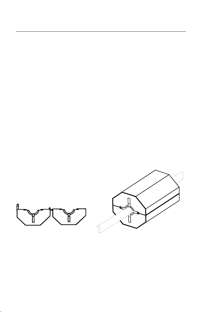
A ferrite collar is included with the RAC6182 and is intended for use with an
Ethernet cable connected to a RAC6182. Install the collar for suppression of
electromagnetic emissions and interference. The collar is required for compliance
with the European EMC directive.
To be effective, the ferrite collar must be placed on the cable where the cable exits
the RAC6182.
To install the ferrite collar:
1. Fold the collar so that it encircles the cable.
2. Press the plastic housing until the collar snaps together.
3. Check that the collar is fully latched.
Open Ferrite Collar
(Side View)
Publication 6182-IN001D-MU-P
Ferrite Collar
Folded Around Cable
Page 16
16 RAC6182 Industrial Computer
Important:
Performance degradation of your Ethernet communications is
likely to result if the unit or cables are subjected to extreme
radiated or conducted high-frequency noise. It is the user’s
responsibility to properly route cable and condition input power
in order to improve communication reliability.
Proper cable routing and power conditioning is required to ensure
reliable Ethernet communications in industrial environments.
Rockwell Automation recommends that all Ethernet cabling be
routed through dedicated metal conduits. Installing ferrite bead
filters at cable ends may also improve reliability.
Replacing the Battery
The RAC6182 Computer contains a battery to maintain the CMOS SRAM and
real-time clock. The battery is located in a battery holder on the RAC6182
Computer backplane. Replace this battery as needed with a Panasonic battery,
part number CR2032.
ATTENTION: There is a danger of explosion if the battery is
incorrectly replaced. Replace only with the same or equivalent
type recommended by the manufacturer. Dispose of used
batteries according to the manufacturer's instructions.
Publication 6182-IN001D-MU-P
Page 17
Notice d'installation
Station industrielle RAC6182
Objet du chapitre
Ce chapitre décrit l'installation de la station industrielle RAC6182 pour le système
d'exploitation Windows CE, ainsi que le montage de la station sur panneau.
Conformité aux directives de l'Union européenne
Lorsqu'elle porte le marquage CE, la station industrielle RAC6182 est conforme
aux directives de l'Union européenne et peut être installée dans les pays de l'Union
européenne et de l'Espace Economique Européen. Une copie de la déclaration de
conformité peut être consultée sur le site Internet de Rockwell Automation /
AllenBradley : www.ab.com
ATTENTION : la station industrielle RAC6182 est conçue
pour être utilisée en milieu industriel ou dans une salle de
commande dans lesquels l'alimentation est isolée des sources
basse tension. Certaines installations peuvent ne pas être
conformes à la norme EN 61000-3-2 (Emissions de courant
harmonique), telle que spécifiée par la directive CEM de
l'Union européenne. Vous devez obtenir une autorisation des
autorités locales avant de connecter tout système qui consomme
plus de 75 watts directement à partir du secteur.
Page 18

18 Station industrielle RAC6182
Environnement
Montez la station RAC6182 sur un panneau ou dans une armoire pour protéger ses
circuits internes. La version à face avant étanche répond aux normes NEMA
Type 1, 12, 13 et 4X (usage intérieur) et CEI IP54, IP65 uniquement si la station
est montée correctement sur un panneau ou dans une armoire répondant à des
normes équivalentes. La version sans écran ne dispose pas de joint et répond aux
normes NEMA Type 1 et CEI 1P2X.
Dans une armoire, laissez un dégagement suffisant pour maintenir une bonne
ventilation. Tenez compte également de la chaleur dégagée par les autres appareils
de l'armoire. La température ambiante autour de la station RAC6182 doit être
maintenue entre 0
dans un environnement avec une pollution de degré 2.
Vérifiez qu'il y a suffisamment d'espace pour accéder à la partie supérieure,
inférieure et aux côtés de la station RAC6182 afin de procéder à l'installation ou
au retrait des composants et d'accéder aux connecteurs.
o
C et 50 oC. La station RAC6182 est destinée à être utilisée
Publication 6182-IN001D-MU-P
Page 19

Station industrielle RAC6182 19
Environnements dangereux
Cet équipement est conçu pour être utilisé dans des environnements de Classe 1,
Division 2, Groupes A, B, C, D ou non dangereux. La mise en garde suivante
s’applique à une utilisation dans des environnements dangereux.
DANGER D’EXPLOSION
• La substitution de composants peut rendre cet équipement
impropre à une utilisation en environnement de Classe 1,
Division 2.
• Ne pas remplacer de composants ou déconnecter
l'équipement sans s'être assuré que l'alimentation est coupée
et que l'environnement est classé non dangereux.
• Ne pas connecter ou déconnecter des composants sans s'être
assuré que l'alimentation est coupée ou que l'environnement
est classé non dangereux.
Publication 6182-IN001D-MU-P
Page 20
20 Station industrielle RAC6182
Matériel de montage
Les versions de la station RAC6182 avec écran sont livrées avec le matériel de
montage suivant.
Pièce Description Quantité Utilisation
Colliers de
fixation
4 colliers Montage sur
panneau ou dans
une armoire
Les colliers de rechange suivants peuvent être commandés auprès de
Rockwell Automation :
Référence Description Quantité Utilisation
6189-2MTGKIT Colliers de
fixation
Jeu de
4 colliers
Pièce de rechange
Outils utilisés
Outre les outils utilisés pour la découpe, vous aurez besoin d'un tournevis
cruciforme n° 2 et d'une clé dynamométrique.
Dégagements
Laissez un espace suffisant pour le montage, la ventilation et la maintenance.
La figure ci-après indique les dégagements minimaux conseillés par rapport aux
autres composants dans le rack ou l'armoire.
ATTENTION : ne jamais faire fonctionner la station RAC6182
dans un espace fermé aux dimensions indiquées ci-après sans
ventilation adéquate ou tout autre système de refroidissement
pour réduire la température à l'intérieur de l'armoire.
Publication 6182-IN001D-MU-P
Page 21
Station industrielle RAC6182 21
Dégagement supérieur
50 mm pour la ventilation
Le dégagement arrière n'est pas
indispensable.
Dégagement côté gauche
102 mm pour la ventilation,
Dégagement inférieur
50 mm pour la ventilation
et les connexions
Dégagement côté droit
25,4 mm pour permettre
l'accès pour le montage
l'accès à la carte PCMCIA et les
connexions
Publication 6182-IN001D-MU-P
Page 22
22 Station industrielle RAC6182
Dimensions de montage
Remarque :
les mesures indiquées sur ces figures sont exprimées en
millimètres [pouces].
Version 7,7 pouces avec clavier
Version 12,1 pouces avec clavier
Publication 6182-IN001D-MU-P
Page 23
Station industrielle RAC6182 23
Version 12,1 pouces sans clavier
Version sans écran
Publication 6182-IN001D-MU-P
Page 24

24 Station industrielle RAC6182
Découpe pour le montage
La figure suivante indique les dimensions de découpe du panneau ou de l'armoire
pour la station RAC6182.
Hauteur
Largeur
Taille de l'écran Hauteur Largeur
Version 7,7 pouces avec clavier 197,8 [7,79] 295,8 [11,65]
Version 12,1 pouces sans clavier 256,8 [10,11] 337,6 [13,29]
Version 12,1 pouces avec clavier 256,8 [10,11] 389,9 [15,35]
Publication 6182-IN001D-MU-P
Page 25
Station industrielle RAC6182 25
Montage sur panneau
Pour installer la station RAC6182 sur un panneau :
ATTENTION : débranchez toute alimentation électrique du
panneau avant de faire la découpe.
Assurez-vous que la zone autour du panneau est dégagée.
Prenez les précautions nécessaires pour qu'aucun copeau
métallique ne pénètre dans un composant déjà installé sur le
panneau.
Le non respect de cette mise en garde risque d'entraîner des
blessures corporelles ou d'endommager les composants du
panneau.
1. Découpez une ouverture dans le panneau à l'aide des dimensions de découpe
appropriées fournies à la page 24.
2. Vérifiez que le joint d'étanchéité de la station RAC6182 est correctement
positionné sur le terminal. Ce joint donne une étanchéité par compression :
ne pas utiliser de produit d'étanchéité
.
3. Placez la station RAC6182 dans la découpe du panneau.
4. Installez les colliers de fixation. Ils s'insèrent dans les fentes situées sur les
parties supérieure et inférieure de la station RAC6182.
Ordre
de serrage
recommandé
Collier de fixation
Publication 6182-IN001D-MU-P
Page 26
26 Station industrielle RAC6182
5. Serrez progressivement les colliers l'un après l'autre autour de la face avant
dans l'ordre indiqué. Répétez ce processus au moins trois fois
jusqu'à ce que
les colliers soient correctement serrés et que le joint soit comprimé
uniformément contre le panneau.
6. Serrez les colliers à 1,1 Nm dans l'ordre indiqué ci-dessus. Ne pas serrer
exagérément.
ATTENTION : serrez les colliers de fixation à 1,1 Nm pour
assurer une étanchéité correcte et éviter d'endommager la
station RAC6182. Rockwell Automation ne saurait être tenu
responsable de dégâts causés par une infiltration d'eau ou de
produit chimique dans le terminal ou dans tout autre
équipement situé dans l'armoire, suite à une installation
incorrecte.
Connexion d'une souris et d'un clavier (panneau latéral)
La souris et le clavier se branchent sur les ports souris et clavier situés sur le côté
de la station, comme indiqué ci-dessous.
Publication 6182-IN001D-MU-P
Page 27
Station industrielle RAC6182 27
Connexion de l'alimentation
Un bornier débrochable à trois contacts sert à connecter l'alimentation à la station
RAC6182. La version c.a. de la station RAC6182 accepte 120/240 V c.a.
L'alimentation électrique est auto-adaptative. La version c.c. accepte 18-32 V c.c.
Les borniers débrochables sont différents sur les versions c.a. et c.c. et ne sont pas
interchangeables.
ATTENTION : l'alimentation électrique doit être connectée à
une prise de terre. En cas de non respect de cette consigne, vous
risquez de vous électrocuter.
Vis
Brochage c.a. Brochage c.c.
de blocage
Terre
Neutre
Phase
Terre
ATTENTION : certaines cartes de communication 1784 ont un
connecteur identique à celui utilisé pour l'alimentation de la
RAC6182.
Ne pas brancher l'alimentation électrique dans ces
connecteurs.
Publication 6182-IN001D-MU-P
Page 28
28 Station industrielle RAC6182
Le bornier externe comporte deux vis de blocage pour éviter une coupure
accidentelle de l'alimentation de la station RAC6182. Serrez les vis à 0,56 Nm sur
la version c.a. ou à 0,28 Nm sur la version c.c.
AVERTISSEMENT : DANGER D'EXPLOSION ! Brancher
ou débrancher l'équipement uniquement si l'alimentation a été
coupée ou si la zone est reconnue non dangereuse.
Les borniers suivants peuvent être commandés auprès de Rockwell Automation :
Référence Description
6189-2CONN Bornier externe 120/240 V c.a. (qté 1)
Bornier externe 24 V c.c (qté 1)
Bornier externe pour sortie relais (qté 1)
Publication 6182-IN001D-MU-P
Page 29

Station industrielle RAC6182 29
Sortie relais
La station RAC6182 comporte une sortie relais. Cette sortie est un relais statique
normalement ouvert dont les valeurs nominales sont 24 V c.c., 500 mA. Un
bornier débrochable à deux contacts sert à connecter cette sortie relais.
Vis de
blocage
Le bornier externe comporte deux vis de blocage pour éviter une déconnexion
accidentelle. Serrez ces vis à 0,56 Nm.
Les borniers externes suivants peuvent être commandés auprès de
Rockwell Automation :
Référence Description
6189-2CONN Bornier externe pour sortie à relais (qté 1)
Bornier externe 120/240 V c.a. (qté 1)
Bornier externe 24 V c.c (qté 1)
Publication 6182-IN001D-MU-P
Page 30

30 Station industrielle RAC6182
(
)
Connexion réseau
La station RAC6182 comporte des connecteurs RJ45 pour réseau Ethernet de
100 Mb/s (câblage CAT5). Un câblage blindé est requis pour la conformité CE.
Une perle de ferrite est livrée avec la station RAC6182. Elle doit être installée sur
le câble Ethernet connecté à la station RAC6182 pour éliminer les émissions et les
interférences électromagnétiques. Cette perle est requise pour la conformité à la
directive CEM de l'Union européenne.
Pour être efficace, la perle doit être placée sur le câble, à la sortie de la RAC6182.
Installation de la perle de ferrite :
1. Enserrez le câble avec la perle.
2. Appuyez sur le boîtier en plastique jusqu'à ce que la perle s'enclenche.
3. Vérifiez que la perle est bien verrouillée.
Perle de ferrite ouverte
Perle de ferrite ouverte
Open Ferrite Collar
(Vue latérale)
(Vue latérale)
Side View
Perle de ferrite fixée
Ferrite Collar
autour du câble
Folded Around Cable
Publication 6182-IN001D-MU-P
Page 31

Station industrielle RAC6182 31
Important :
Il est possible de constater une baisse des performances des
communications Ethernet si l'équipement ou les câbles sont
exposés à d'importantes perturbations de haute fréquence
transmises par rayonnement ou conduction. Il incombe à
l'utilisateur d'acheminer correctement les câbles et d'assurer le
conditionnement correct de l'alimentation afin d'améliorer la
fiabilité des communications, en particulier des communications
Ethernet en milieu industriel. Rockwell Automation recommande
d'acheminer tous les câblages Ethernet à travers des conduits
métalliques dédiés. L'installation de filtres à perle de ferrite aux
extrémités des câbles peut également améliorer la fiabilité.
Remplacement de la pile
La station RAC6182 contient une pile qui conserve la mémoire CMOS SRAM et
l'horloge temps réel. Cette pile se trouve dans un compartiment situé sur le fond
de panier de la station RAC6182. Remplacez la pile lorsque c'est nécessaire par
une pile Panasonic, référence CR2032.
ATTENTION : il y a danger d'explosion si la pile de rechange
n'est pas correcte. La remplacer uniquement avec une pile
identique ou de type équivalent, conformément aux
recommandations du fabricant. Se conformer aux directives du
fabricant pour mettre la pile au rebut.
Publication 6182-IN001D-MU-P
Page 32

Installationsanleitung
Industriecomputer RAC6182
Inhalt
Dieses Kapitel beschreibt die Installation des Industriecomputers RAC6182 für
das Betriebssystem Windows CE und den Einbau des RAC6182 in einen
Schaltschrank mithilfe von Montageklammern.
EUKonformität
Die Industriecomputer RAC6182 erfüllen die Anforderungen der EU-Richtlinien,
wenn sie innerhalb der Europäischen Union oder der EWR-Regionen installiert
werden und das CE-Zeichen tragen. Die Konformitätserklärung (Declaration of
Conformity) kann auf der folgenden Internet-Seite von Rockwell Automation/
AllenBradley eingesehen werden: www.ab.com
ACHTUNG: Der Industriecomputer RAC6182 wurde für den
Betrieb in einer industriellen Umgebung bzw. in einer
Steuerwarte entwickelt, wo bereits eine gewisse Art der
Trennung vom öffentlichen Spannungsnetz verwendet wird.
Einige Konfigurationen entsprechen eventuell nicht dem
Standard EN 61000-3-2 zu Oberschwingungsströmen, wie
durch die EMV-Richtlinie der Europäischen Union festgelegt.
Daher müssen Sie vor dem Anschließen eines Computers mit
einer Leistungsaufnahme von über 75 Watt AC-Leistung direkt
über das öffentliche Stromnetz zunächst die Erlaubnis des
lokalen Stromversorgers einholen.
Page 33

Industriecomputer RAC6182 33
Hinweise zu den Umgebungsbedingungen
Bauen Sie den Computer RAC6182 in einen Schaltschrank oder in ein Gehäuse
ein, um die internen Schaltungen zu schützen. Die Ausführungen mit Dichtung
erfüllen NEMATyp 1, 12, 13 und 4X (Innenraumverwendung) und IEC IP54,
IP65 nur dann, wenn sie ordnungsgemäß in einen Schaltschrank oder in ein
Gehäuse mit der gleichen Schutzart eingebaut werden. Die Ausführungen ohne
Anzeige haben keine Dichtung und erfüllen NEMA-Typ 1 und IEC IP2X.
Lassen Sie genügend Platz im Gehäuse für eine ausreichende Belüftung. Beachten
Sie, dass auch andere Geräte im Gehäuse Wärme abgeben. Die
Umgebungstemperatur für den Computer RAC6182 muss zwischen 0
o
C liegen. Der Computer RAC6182 wurde für den Einsatz in Umgebungen mit
50
Verschmutzungsgrad 2 konzipiert.
Achten Sie darauf, dass Sie an der Ober- und Unterseite sowie an den Seiten des
Computers RAC6182 genügend Platz lassen, damit Sie Komponenten ein- und
ausbauen sowie auf die Anschlüsse zugreifen können.
o
C und
Publikation 6182-IN001D-MU-P
Page 34

34 Industriecomputer RAC6182
Gefährliche Standorte
Dieses Gerät eignet sich ausschließlich für den Einsatz in Gefahrenbereichen der
Klasse I, Division 2, Gruppen A, B, C, D, oder in nicht gefährlichen Bereichen. Die
folgende WARNUNG bezieht sich auf den Einsatz in gefährlichen Umgebungen.
ACHTUNG: EXPLOSIONSGEFAHR!
• Der Austausch von Komponenten kann die Eignung des
Geräts für die Klasse I, Division 2 beeinträchtigen.
• Kompontenten dürfen erst dann ausgetauscht und Geräte
erst dann abgeklemmt werden, wenn die
Spannungsversorgung ausgeschaltet wurde oder der Bereich
als ungefährlich gilt.
• Komponenten dürfen erst dann angeschlossen oder
abgeklemmt werden, wenn die Spannungsversorgung
ausgeschaltet wurde oder der Bereich als ungefährlich gilt.
• Die gesamte Verdrahtung muss gemäß N.E.C. Artikel
501-4(b) erfolgen.
Publikation 6182-IN001D-MU-P
Page 35

Industriecomputer RAC6182 35
Montagezubehör
Die mit einer Anzeige ausgestatteten Ausführungen des Computers RAC6182
werden mit folgendem Montagezubehör ausgeliefert.
Artikel Beschreibung Menge Zweck
Montageklammern 4 Klammern Schaltschrank oder
Gehäuseeinbau
Folgende Ersatzklammern können bei Rockwell Automation bestellt werden:
Teilenummer Beschreibung Menge Zweck
6189-2MTGKIT Montageklammern Paket mit 4
Klammern
Ersatzteil
Benötigte Werkzeuge
Neben den Werkzeugen für den Ausschnitt benötigen Sie noch einen
Kreuzschlitzschraubendreher #2 sowie einen Drehmomentschlüssel.
Montagefreiraum
Lassen Sie genügend Platz für Montage, Belüftung und Wartung. Die folgenden
Abbildungen zeigen die empfohlenen Mindestabstände zu anderen Komponenten
im Rack oder Gehäuse.
ACHTUNG: Der Computer RAC6182 darf nicht in einem
Raum mit geringeren als den im Folgenden aufgeführten
Abmessungen betrieben werden, es sei denn, es wird für eine
angemessene Belüftung oder eine andere Form der Kühlung
gesorgt, um die Lufttemperatur im Gehäuse gering zu halten.
Publikation 6182-IN001D-MU-P
Page 36

36 Industriecomputer RAC6182
Montagefreiraum Unterseite
50 mm für Luftstrom
und Kabelanschlüsse
Montagefreiraum rechte Seite
25,4 mm für Zugriff
bei der Montage
Montagefreiraum Oberseite
50 mm für Luftstrom
An der Rückseite ist kein
Montagefreiraum erforderlich.
Montagefreiraum linke Seite
102 mm für Luftstrom,
Zugang zur PCMCIA-Karte und
Kabelanschlüsse
Publikation 6182-IN001D-MU-P
Page 37

Industriecomputer RAC6182 37
Einbaumaße
Hinweis:
Die Maße sind in den Abbildungen in mm angegeben.
7,7-Zoll-Ausführung mit Tastatur
223,6
12,1-Zoll-Ausführung mit Tastatur
387,9
282,6
321,5
293,8
195,8
75,4
286,8
Publikation 6182-IN001D-MU-P
195,8
415,7
75,8
Page 38

38 Industriecomputer RAC6182
12,1-Zoll-Ausführung ohne Tastatur
282,6
Ausführung ohne Anzeige
195,8
335,5
276,0
195,8
363,3
75,8
276,0
195,8
330,2
57,3
Publikation 6182-IN001D-MU-P
Page 39

Industriecomputer RAC6182 39
Montage-Ausschnitte
Die nachfolgende Abbildung zeigt die Abmessungen für den Schaltschrank- oder
Gehäuseausschnitt des Computers RAC6182.
Höhe
Breite
Anzeigengröße Höhe Breite
7,7-Zoll-Ausführung mit Tastatur 197,8 295,8
12,1-Zoll-Ausführung ohne Tastatur 256,8 337,6
12,1-Zoll-Ausführung mit Tastatur 256,8 389,9
Publikation 6182-IN001D-MU-P
Page 40

40 Industriecomputer RAC6182
Einbau in den Schaltschrank
So wird der Computer RAC6182 in einen Schaltschrank eingebaut:
ACHTUNG: Schalten Sie die Spannungsversorgung für den
Schaltschrank ab, bevor Sie den Ausschnitt anfertigen.
Achten Sie darauf, dass der Bereich um den Schaltschrankausschnitt
frei ist.
Treffen Sie Vorsichtsmaßnahmen, damit keine Metallspäne in die
bereits im Schaltschrank eingebauten Komponenten eindringen
können.
Bei Nichtbeachten dieser Warnhinweise kann es zu Verletzungen
und/oder Beschädigungen der Schaltschrankkomponenten kommen.
1. Schneiden Sie mit Hilfe der auf Seite 39 dargestellten Ausschnittmaße eine
Öffnung in den Schaltschrank.
2. Achten Sie darauf, dass die Dichtung für den Computer RAC6182 richtig am
Gerät angebracht ist. Die Dichtung erfolgt durch Kompression. Verwenden
Sie keine zusätzlichen Dichtungsmittel.
3. Setzen Sie den Computer RAC6182 in den Montage-Ausschnitt im
Schaltschrank ein.
4. Bringen Sie die Montageklammern an. Die Montageklammern schieben sich
in die dafür vorgesehenen Öffnungen an der Ober- und Unterseite des
Computers RAC6182.
Empfohlene
Anzugs-
reihenfolge
Publikation 6182-IN001D-MU-P
Montageklammern
Page 41

Industriecomputer RAC6182 41
5. Ziehen Sie die Klammern rund um die Frontplatte nur stufenweise und in der
angegebenen Reihenfolge nacheinander fest. Wiederholen Sie diesen
Vorgang mindestens dreimal
, bis die Klammern handfest sitzen und die
Dichtung gleichmäßig gegen den Schaltschrank gedrückt wird.
6. Ziehen Sie die Montageklammern in der oben beschriebenen Reihenfolge mit
einem Anzugsmoment von 1,1 Nm fest. Achten Sie darauf, dass Sie die
Klammern nicht zu stark anziehen.
ACHTUNG: Ziehen Sie die Montageklammern mit einem
Anzugsmoment von 1,1 Nm fest, um eine angemessene
Abdichtung zu erreichen und Schäden am RAC6182 zu
vermeiden. Rockwell Automation übernimmt bei
unsachgemäßer Installation keine Haftung für Schäden durch
Wasser oder Chemikalien am Computer oder an anderen
Geräten innerhalb des Gehäuses.
Anschließen von Maus und Tastatur (Seitenwand)
Die Maus und die Tastatur werden wie unten dargestellt an den Schnittstellen für
Maus und Tastatur seitlich am Gerät angeschlossen.
Publikation 6182-IN001D-MU-P
Page 42

42 Industriecomputer RAC6182
Anschließen der Spannungsversorgung
Der Computer RAC6182 wird über eine abnehmbare Klemmenleiste mit drei
Kontakten an die Spannungsversorgung angeschlossen. Die AC-Ausführung des
RAC6182 kann mit 120/240 V AC arbeiten. Das Gerät erkennt die angelegte
Spannung automatisch. Die DC-Ausführung kann mit 18–32 V DC arbeiten. Die
abnehmbaren Klemmenleisten der AC- und DC-Ausführungen des 6182
unterscheiden sich voneinander und können daher nicht untereinander
ausgetauscht werden.
ACHTUNG: Die Spannungsversorgung muss geerdet werden.
Bei Nichtbeachten dieser Warnung könnte es zu schwerem
Stromschlag kommen.
AC-Kontaktstift DC-Kontaktstift
Neutral
Spannungsführend
Erde
Erde
ACHTUNG: Einige Kommunikationskarten der Serie 1784
sind mit einem Steckverbinder ausgestattet, wie er auch für den
Stromanschluss des RAC6182 verwendet wird.
Achten Sie unbedingt darauf, die Spannungsversorgung
niemals an diese Steckverbinder anzuschließen!
Halteschrauben
Publikation 6182-IN001D-MU-P
Page 43

Industriecomputer RAC6182 43
Die Klemmenleiste ist mit zwei Halteschrauben ausgerüstet, um eine
unbeabsichtigte Unterbrechung der Stromversorgung zum RAC6182 zu
verhindern. Ziehen Sie die Schrauben auf der AC-Ausführung bis zu einem
Anzugsmoment von 0,56 Nm an. Ziehen Sie die Schrauben an der DCAusführung bis zu einem Anzugsmoment von 0,28 Nm an.
WARNUNG: EXPLOSIONSGEFAHR! Achten Sie unbedingt
darauf, die Stromversorgung abzuschalten bzw. vergewissern
Sie sich, dass der Standort KEIN explosionsgefährdeter
Standort ist, bevor Sie Geräte anschließen oder abklemmen.
Folgende Klemmenleisten können bei Rockwell Automation bestellt werden:
Teilenummer Beschreibung
6189-2CONN Klemmenleiste für 120/240-V-AC-Ausf. (1 Stück)
Klemmenleiste für 24-V-DC-Ausf. (1 Stück)
Klemmenleiste für Relaisausgang (1 Stück)
Publikation 6182-IN001D-MU-P
Page 44

44 Industriecomputer RAC6182
Relaisausgang
Der Computer RAC6182 ist mit einem Relaisausgang ausgestattet. Hierbei
handelt es sich um ein Schließer-Kontaktrelais, das für 24 V DC, 500 mA
ausgelegt ist. Für den Anschluss an den Relaisausgang wird eine abnehmbare
Klemmenleiste mit zwei Kontakten verwendet.
Halteschrauben
Die Klemmenleiste verfügt über zwei Halteschrauben, um eine unbeabsichtigte
Unterbrechung der Stromversorgung zu verhindern. Ziehen Sie diese Schrauben
bis zu einem Anzugsmoment von 0,56 Nm fest.
Folgende Ersatz-Klemmenleisten für den Relaisausgang können bei Rockwell
Automation bezogen werden:
Teilenummer Beschreibung
6189-2CONN Klemmenleiste für Relaisausgang (1 Stück)
Klemmenleiste für 120/240-V-AC-Ausf. (1 Stück)
Klemmenleiste für 24-V-DC-Ausf. (1 Stück)
Publikation 6182-IN001D-MU-P
Page 45

Industriecomputer RAC6182 45
(
)
Anschluss an ein Netzwerk
An den RAC6182 kann ein paarweise verdrilltes CAT5-Ethernet-Kabel mit RJ45Steckverbindern für die Datenübertragung im Netz mit 100 Mbit/s angeschlossen
werden. Zur Erfüllung der CE-Norm ist ein geschirmtes Kabel erforderlich.
Der RAC6182 wird mit einer Ferritmanschette geliefert, die zum Anschließen
eines Ethernet-Kabels am RAC6182 vorgesehen ist. Bringen Sie die Manschette
zur Unterdrückung von elektromagnetischen Emissionen und Störungen an. Die
Manschette ist zur Einhaltung der EMV-Richtlinie erforderlich.
Die Ferritmanschette muss an der Stelle angebracht werden, an der das Kabel aus
dem RAC6182 austritt.
So bringen Sie die Ferritmanschette an:
1. Falten Sie die Manschette so zusammen, dass sie das Kabel umgibt.
2. Drücken Sie das Kunststoffgehäuse zusammen, bis die Manschette einrastet.
3. Überprüfen Sie, ob die Manschette fest sitzt und vollständig eingerastet ist.
Offene Ferritmanschette
Offene Ferritmanschette
Open Ferrite Collar
(Seitenansicht)
(Seitenansicht)
Side View
Publikation 6182-IN001D-MU-P
Ferritmanschette
Ferrite Collar
um Kabel gefaltet
Folded Around Cable
Page 46

46 Industriecomputer RAC6182
Wichtig:
Wird das Gerät oder die Verkabelung extremen abgestrahlten
oder geleiteten Hochfrequenzstörungen ausgesetzt, kann dies eine
Leistungsminderung der Ethernet-Kommunikation bewirken. Es
liegt in der Verantwortung des Anwenders, die Kabel sachgemäß
zu verlegen und die Eingangsspannung so aufzubereiten, dass die
Zuverlässigkeit der Kommunikation gewährleistet ist.
Die sachgemäße Kabelverlegung und Spannungsversorgung sind
für eine zuverlässige Ethernet-Kommunikation in
Industrieumgebungen unabdingbar. Rockwell Automation
empfiehlt, die Ethernet-Kabel in eigenen Metallschutzrohren zu
verlegen. Die Zuverlässigkeit kann auch durch Installieren von
Ferritfiltern an den Kabelenden erhöht werden.
Auswechseln der Batterie
Der Computer RAC6182 ist mit einer Batterie ausgestattet, die den CMOS SRAM
und die Echtzeituhr mit Spannung versorgt. Die Batterie befindet sich in einer
Batteriehalterung an der Backplane des RAC6182. Ersetzen Sie diese Batterie bei
Bedarf durch eine Panasonic-Batterie (Teilenummer CR2032).
ACHTUNG: Beim Einsetzen einer falschen Batterie besteht
Explosionsgefahr. Verwenden Sie nur Batterien desselben Typs
oder gleichwertige Batterien gemäß den Empfehlungen des
Herstellers. Entsorgen Sie leere Batterien gemäß den
Anweisungen des Herstellers.
Publikation 6182-IN001D-MU-P
Page 47

Instrucciones de instalación
Computadora industrial RAC6182
Objetivo del capítulo
Este capítulo describe la instalación de la computadora industrial RAC6182 para
el sistema operativo Windows CE e incluye cómo instalar la computadora
RAC6182 en un panel usando abrazaderas de montaje.
Conformidad con especificaciones de la Unión Europea
La computadora industrial RAC6182 cumple con los requisitos de la Directiva de
la Unión Europea cuando se instala dentro de la Unión Europea o regiones EEA y
tiene la marca CE. Una copia de la Declaración de Conformidad está disponible
en la página de Internet de Rockwell Automation/AllenBradley: www.ab.com
ATENCIÓN: La computadora industrial RAC6182 está
diseñada para funcionar en un ambiente industrial o en una sala
de control que cuente con alguna forma de aislamiento de
alimentación de las líneas de bajo voltaje de servicio público.
Es posible que algunas configuraciones no cumplan con la
normativa EN 61000-3-2 de emisiones de armónicas según lo
especificado por la directiva EMC de la Unión Europea.
Obtenga permiso de la autoridad local del servicio de
alimentación eléctrica antes de conectar una configuración que
consuma más de 75 watts de alimentación de CA directamente
de las líneas de servicio público.
Page 48

48 Computadora industrial RAC6182
Consideraciones del entorno
Monte la computadora RAC6182 en un panel o envolvente para proteger los
circuitos internos. Las versiones con junta de bisel cumplen los requisitos NEMA
tipo 1, 12, 13 y 4X (uso en interiores) e IEC IP54, IP65 sólo cuando se montan
correctamente en un panel o caja que tenga una clasificación equivalente. La
versión sin pantalla no tiene empaquetadura y tiene clasificación NEMA Tipo 1 e
IEC 1P2X.
Deje suficiente espacio dentro de la caja para que haya una ventilación adecuada.
Tenga en cuenta también el calor producido por otros dispositivos que pueda
haber en la caja. La temperatura alrededor de la computadora RAC6182 debe
mantenerse entre 0° y 50 °C (32° a 122 °F). La computadora RAC6182 está
diseñada para uso en ambientes con contaminación de grado 2.
Asegúrese de proporcionar acceso a los paneles superior, inferior y laterales de la
computadora RAC6182 para instalar o desmontar componentes y para tener
acceso a los conectores.
Publicación 6182-IN001D-MU-P
Page 49

Computadora industrial RAC6182 49
Consideraciones específicas para lugares peligrosos
Este equipo es apto para uso en lugares Clase I, División 2, Grupos A, B, C, D o
en lugares no peligrosos solamente. La siguiente ADVERTENCIA se aplica para
uso en lugares peligrosos.
ATENCIÓN: PELIGRO DE EXPLOSIÓN
• La sustitución de componentes puede afectar la idoneidad
para Clase I, División 2.
• No reemplace componentes ni desconecte equipos a menos
que haya desconectado la alimentación eléctrica o el área se
considere no peligrosa.
• No conecte ni desconecte componentes a menos que haya
desconectado la alimentación eléctrica o el área se considere
no peligrosa.
• Todo el cableado debe cumplir con las especificaciones de
N.E.C. artículo 501-4(b).
Publicación 6182-IN001D-MU-P
Page 50

50 Computadora industrial RAC6182
Tornillería de montaje
Las versiones de la computadora RAC6182 con pantalla se envían con la siguiente
tornillería de montaje.
Artículo Descripción Cantidad Usar para
Abrazaderas
de montaje
4 abrazaderas Montaje en panel o
envolvente
Las siguientes abrazaderas de repuesto se pueden pedir a Rockwell Automation:
Número de pieza Descripción Cantidad Usar para
6189-2MTGKIT Abrazaderas
de montaje
Paquete de 4
abrazaderas
Ítem de repuesto
Herramientas necesarias
Además de las herramientas requeridas para el corte, necesitará un destornillador
Phillips #2 y una llave dinamométrica.
Espacios libres para el montaje
Deje espacios adecuados para el montaje, el flujo de aire y el mantenimiento. La
ilustración de abajo muestra el espacio mínimo que se recomienda para otros
componentes dentro del rack o el envolvente.
ATENCIÓN: La computadora RAC6182 no debe funcionar en
un espacio pequeño como el que se muestra abajo salvo que se
proporcione ventilación adecuada o se usen otros métodos de
enfriamiento para reducir la temperatura dentro del envolvente.
Publicación 6182-IN001D-MU-P
Page 51

Computadora industrial RAC6182 51
Espacio libre en la parte superior
50 mm (2 pulg.) para flujo de aire
El espacio libre en la parte posterior
puede ser cero.
Espacio libre al lado izquierdo
102 mm (4 pulg.) para flujo de aire,
Espacio libre en la parte inferior
50 mm (2 pulg.) para flujo de aire
y conexiones de cables
Espacio libre al lado derecho
25.4 mm (1 pulg.) para permitir
acceso para el montaje
acceso para tarjeta PCMCIA y
conexiones de cables
Publicación 6182-IN001D-MU-P
Page 52

52 Computadora industrial RAC6182
Dimensiones de montaje
Nota:
Las medidas en estas figuras se proporcionan en milímetros
[pulgadas].
Versión de 7.7 pulg. con teclado
Versión de 12.1 pulg. con teclado
Publicación 6182-IN001D-MU-P
Page 53

Computadora industrial RAC6182 53
Versión de 12.1 pulg. sin teclado
Versión sin pantalla
Publicación 6182-IN001D-MU-P
Page 54

54 Computadora industrial RAC6182
A
A
Cortes para montaje
La siguiente figura proporciona las dimensiones para hacer el corte en el panel o
envolvente para la computadora RAC6182.
tura
ncho
Tamaño de pantalla Altura Ancho
Versión de 7.7 pulg. con teclado 197.8 [7.79] 295.8 [11.65]
Versión de 12.1 pulg. sin teclado 256.8 [10.11] 337.6 [13.29]
Versión de 12.1 con teclado 256.8 [10.11] 389.9 [15.35]
Publicación 6182-IN001D-MU-P
Page 55

Computadora industrial RAC6182 55
Montaje en panel
Para instalar la computadora RAC6182 en un panel:
ATENCIÓN: Desconectar completamente la alimentación
eléctrica del panel antes de hacer el corte.
Asegurarse de que el área alrededor del panel esté libre.
Tomar precauciones para que las virutas de metal no entren en
los componentes ya instalados en el panel.
El no seguir estas advertencias puede causar lesiones personales
o daños en los componentes del panel.
1. Haga una abertura en el panel utilizando las dimensiones de corte indicadas
en la página 54.
2. Asegúrese de que la empaquetadura de sello de la computadora RAC6182
esté colocada correctamente en el terminal. Esta empaquetadura forma un
sello tipo compresión. No use compuestos selladores
3. Coloque la computadora RAC6182 en el corte del panel.
.
4. Instale las abrazaderas de montaje. Las abrazaderas de montaje se deslizan en
las ranuras ubicadas en la parte superior e inferior de la computadora
RAC6182.
Secuencia
de par de apriete
recomendada
Publicación 6182-IN001D-MU-P
Abrazaderas
de montaje
Page 56

56 Computadora industrial RAC6182
5. Apriete gradualmente las abrazaderas una a la vez alrededor del bisel en la
secuencia especificada. Repita este proceso por lo menos tres veces
hasta que
las abrazaderas estén apretadas manualmente y la empaquetadura esté
comprimida de manera uniforme contra el panel.
6. Apriete las abrazaderas de montaje a un par de 10 pulg.-libras (1.1 N•m) en la
secuencia mostrada anteriormente. No sobreapriete.
ATENCIÓN: Apriete las abrazaderas de montaje a un par de
10 pulg.-libras para proporcionar un sello adecuado y evitar
daño a la computadora RAC6182 Rockwell Automation no
asume responsabilidad por daño producido por agua o
productos químicos que ingresen al terminal u otros equipos
dentro del envolvente debido a una instalación incorrecta.
Conexión de un mouse y teclado (panel lateral)
El mouse y el teclado se conectan a los puertos para mouse y teclado del panel
lateral tal como se muestra abajo.
Publicación 6182-IN001D-MU-P
Page 57

Computadora industrial RAC6182 57
Conexiones de alimentación eléctrica
Se utiliza un bloque de terminales extraíble de tres contactos para conectar la
alimentación eléctrica a la computadora RAC6182. La versión de CA de la
computadora RAC6182 acepta 120/240 VCA. La fuente de alimentación es de
rango automático. La versión de CC acepta 18-32 VCC. Los bloques de
terminales extraíbles son diferentes en las versiones de CA y CC y no se pueden
intercambiar.
ATENCIÓN: La fuente de alimentación eléctrica debe tener
conexión a tierra. El no seguir esta advertencia puede causar
descargas eléctricas peligrosas.
Configuración de
pines de CA
Tierra
Caliente
Neutro
Configuración de
pines de CC
Tierra
ATENCIÓN: Algunas tarjetas de comunicación 1784 tienen un
conector como el usado para la conexión de alimentación de la
computadora RAC6182.
No enchufe la alimentación eléctrica en estos conectores.
Publicación 6182-IN001D-MU-P
Tornillos
de
retención
Page 58

58 Computadora industrial RAC6182
El bloque de terminales está equipado con dos tornillos de retención para evitar
una interrupción accidental de la alimentación eléctrica de la computadora
RAC6182. Apriete los tornillos en la versión de CA a un par de apriete de 5 pulg.libras (0.56 N•m). Apriete los tornillos en la versión de CC a un par de apriete de
2.5 pulg.-libras (0.28 N•m).
ADVERTENCIA: ¡PELIGRO DE EXPLOSIÓN! No conecte
ni desconecte el equipo a menos que la alimentación eléctrica
haya sido desconectada o el área se considere no peligrosa.
Los siguientes bloques de terminales se pueden pedir a Rockwell Automation:
Número de pieza Descripción
6189-2CONN Bloque de terminales de unidad de 120/240 VCA
(paquete de 1)
Bloque de terminales de unidad de 24 VCC
(paquete de 1)
Bloque de terminales de salida de relé
(paquete de 1)
Publicación 6182-IN001D-MU-P
Page 59

Computadora industrial RAC6182 59
Salida de relé
La computadora RAC6182 tiene una salida de relé. Esta es una salida de relé
normalmente abierta, de contacto duro, para 24 VCC, 500 mA. Se utiliza un
bloque de terminales extraíble de dos contactos para hacer conexión a la salida de
relé.
Tornillos de
retención
El bloque de terminales está equipado con dos tornillos de retención para evitar
una desconexión accidental. Apriete estos tornillos a un par de 5 pulg.-libras
(0.56 N•m).
Los siguientes bloques de terminales de salida de relé de repuesto se pueden pedir
a Rockwell Automation:
Número de pieza Descripción
6189-2CONN Bloque de terminales de salida de relé
(paquete de 1)
Bloque de terminales de unidad de 120/240 VCA
(paquete de 1)
Bloque de terminales de unidad de 24 VCC
(paquete de 1)
Publicación 6182-IN001D-MU-P
Page 60

60 Computadora industrial RAC6182
(
)
Conexiones de red
La computadora RAC6182 acepta cables Ethernet de par trenzado CAT5 con
conectores RJ45 que permiten la transferencia de datos a 100 Mbps por una red.
Se requiere cableado blindado para cumplir con las especificaciones de CE.
Se incluye un collarín de ferrita con la RAC6182, el cual está diseñado para uso
con un cable Ethernet conectado a una RAC6182. Instale el collarín para suprimir
las emisiones e interferencias electromagnéticas. El collarín es requisito para
cumplir con la directiva de EMC de Europa.
Para ser eficaz, el collarín de ferrita debe colocarse en el cable donde éste sale de
la RAC6182.
Para instalar el collarín de ferrita:
1. Doble el collarín de manera que envuelva al cable.
2. Presione el envolvente de plástico hasta que el collarín encaje.
3. Verifique que el collarín esté firmemente fijado.
Collarín de ferrita abierto
Collarín de ferrita abierto
Open Ferrite Collar
(Vista lateral)
(Vista lateral)
Side View
Collarín de ferrita
Ferrite Collar
Doblado alrededor del cable
Folded Around Cable
Publicación 6182-IN001D-MU-P
Page 61

Computadora industrial RAC6182 61
Importante:
Es probable que las comunicaciones Ethernet se vean
degradadas si la unidad o los cables son sometidos a ruidos
extremos de alta frecuencia ya sean radiados o conducidos. El
usuario es responsable de instalar los cables y acondicionar la
alimentación eléctrica de entrada a fin de mejorar la fiabilidad
de las comunicaciones.
Es necesario instalar los cables y acondicionar la alimentación
eléctrica correctamente para asegurar que las comunicaciones
por Ethernet sean fiables en un ambiente industrial. Rockwell
Automation recomienda que todos los cables Ethernet se
instalen a través de conductos metálicos especialmente
asignados. La instalación de filtros con núcleo de ferrita en los
extremos de los cables también puede mejorar la fiabilidad de
las comunicaciones.
Cómo reemplazar la batería
La computadora RAC6182 contiene una batería para mantener la SRAM CMOS y
el reloj en tiempo real. La batería está ubicada en el portabatería situado en el
backplane de la computadora RAC6182. Reemplace esta batería según sea
necesario con una batería Panasonic, número de pieza CR2032.
ATENCIÓN: Existe el peligro de explosión si la batería se
reemplaza incorrectamente. Reemplácela sólo con una del
mismo tipo o equivalente recomendada por el fabricante.
Deseche las baterías usadas siguiendo las instrucciones del
fabricante.
Publicación 6182-IN001D-MU-P
Page 62

Istruzioni per l'Installazione
Computer industriale RAC6182
Obiettivi del capitolo
Questo capitolo descrive l'installazione del computer industriale RAC6182 per il
sistema operativo Windows CE, compresa la procedura di montaggio del
RAC6182 a pannello mediante clip di montaggio.
Conformità alle norme dell'Unione Europea
Il computer industriale RAC6182 è conforme ai requisiti delle Direttive
dell'Unione Europea quando installato nei paesi dell'Unione Europea o EEA e reca
il marchio CE. Una copia della Dichiarazione di Conformità può essere ottenuta
collegandosi al sito Internet della Rockwell Automation / AllenBradley:
www.ab.com
ATTENZIONE: Il computer industriale RAC6182 è destinato
all'uso in ambiente industriale o sale di controllo, dove sia
installata qualche forma di isolamento dell'alimentazione dalla
rete pubblica a bassa tensione. Alcune configurazioni possono
non essere conformi allo standard sulle Emissioni di Armoniche
EN 61000-3-2 come specificato dalla Direttiva EMC
dell'Unione Europea. Chiedere l'autorizzazione al locale ente
per l'energia elettrica prima di collegare qualsiasi
configurazione che assorba più di 75 watt di corrente alternata
direttamente dalla rete pubblica.
Page 63

Computer industriale RAC6182 63
Considerazioni ambientali
Montare il computer RAC6182 a pannello o in una custodia per proteggere il
circuito interno. Le versioni munite di cornice con guarnizione di tenuta sono
conformi al Tipo NEMA 1, 12, 13 e 4X (per l'interno) e IEC 1P54, 1P65 solo se
montate a pannello o in una custodia di classe equivalente. La versione senza
display non dispone di guarnizione di tenuta ed è di classe Tipo NEMA 1 e
IEC 1P2X.
È necessario lasciare sufficiente spazio nella custodia per un'adeguata
ventilazione. Considerare anche il calore prodotto da altri dispositivi nella
custodia. La temperatura ambiente all'esterno del RAC6182 deve essere
mantenuta tra 0
in ambienti con inquinamento di grado 2.
Garantire l'accesso ai pannelli superiore, inferiore e laterali del computer
RAC6182 per installare o rimuovere i componenti e per accedere ai connettori.
o
e 50 oC (da 32 o a 122 oF). È previsto l'uso del computer RAC6182
Pubblicazione
6182-IN001D-MU-P
Page 64

64 Computer industriale RAC6182
Considerazioni sugli ambienti pericolosi
Questo dispositivo può essere utilizzato solo in luoghi appartenenti alla Classe I,
Divisione 2, Gruppi A, B, C, D oppure in luoghi non pericolosi. La seguente
AVVERTENZA si riferisce all'impiego in ambienti pericolosi.
ATTENZIONE: PERICOLO DI ESPLOSIONE.
• La sostituzione dei componenti può rendere questo
dispositivo inadatto per l'uso in ambienti di Classe I,
Divisione 2.
• Non sostituire i componenti o scollegare il dispositivo prima
di essersi accertati che l'alimentazione sia stata scollegata e
che l'area sia immune da pericoli.
• Non collegare o scollegare i componenti prima di essersi
accertati che l'alimentazione sia stata scollegata e che l'area
sia immune da pericoli.
• Tutti i cablaggi devono essere conformi all'articolo N.E.C.
501-4(b).
Pubblicazione
6182-IN001D-MU-P
Page 65

Computer industriale RAC6182 65
Componenti per il montaggio
Le versioni del computer RAC6182 dotate di display vengono fornite con il
seguente materiale per il montaggio.
Art. Descrizione Quantità Utilizzare per
Graffe di
montaggio
4 graffe Il montaggio a
pannello o in
custodia
È possibile ordinare le seguenti graffe di ricambio presso la Rockwell
Automation:
Numero parte Descrizione Quantità Utilizzare per
6189-2MTGKIT Graffe di
montaggio
Confezione da
4 graffe
Articolo di ricambio
Attrezzi necessari
Oltre agli attrezzi necessari per eseguire le aperture, è necessario un cacciavite a
croce n. 2 e una chiave torsiometrica.
Distanze per il montaggio
Lasciare adeguato spazio per il montaggio, la circolazione dell'aria e la
manutenzione. La figura di seguito riportata riporta le distanze minime da
mantenere dagli altri componenti nella custodia o nel rack.
ATTENZIONE: Il computer RAC6182 non può essere
impiegato in spazi inferiori a quelli di seguito riportati a meno
che non ci sia adeguata ventilazione o che non vengano
utilizzati altri metodi di raffreddamento per abbassare la
temperatura dell'aria dentro la custodia.
Pubblicazione
6182-IN001D-MU-P
Page 66

66 Computer industriale RAC6182
Distanza lato inferiore
50 mm (2 poll.) per il passaggio
dell'aria e i collegamenti dei cavi
Distanza lato destro
25,4 mm (1 poll.) per consentire
l'accesso per il montaggio
Distanza lato superiore
50 mm (2 poll.) per il passaggio
dell'aria
La distanza del lato posteriore può
essere zero.
Distanza lato sinistro 102 mm (4 poll.)
per il passaggio dell'aria,
l'accesso alla scheda PCMCIA e
alle connessioni dei cavi
Pubblicazione
6182-IN001D-MU-P
Page 67

Computer industriale RAC6182 67
Dimensioni per il montaggio
Nota:
Le misure riportate in queste figure sono espresse in millimetri
[pollici].
Versione da 7,7" con tastierino
Versione da 12,1" con tastierino
Pubblicazione
6182-IN001D-MU-P
Page 68

68 Computer industriale RAC6182
Versione da 12,1" senza tastierino
Versione senza display
Pubblicazione
6182-IN001D-MU-P
Page 69

Computer industriale RAC6182 69
Tagli per il montaggio
L'illustrazione sottostante fornisce le dimensioni per il taglio del pannello o della
custodia per il computer RAC6182.
Altezza
Larghezz
Dimensione display Altezza Larghezza
Versione da 7,7" con tastierino 197,8 [7,79] 295,8 [11.65]
Versione da 12,1" senza tastierino 256,8 [10,11] 337,6 [13,29]
Versione da 12,1" con tastierino 256,8 [10,11] 389,9 [15,35]
Pubblicazione
6182-IN001D-MU-P
Page 70

70 Computer industriale RAC6182
Montaggio a pannello
Per installare il computer RAC6182 a pannello:
ATTENZIONE: Disinserire tutta l'alimentazione elettrica dal
pannello prima di eseguire i tagli.
Accertarsi che l'area attorno al taglio del pannello sia libera.
Evitare che frammenti di metallo penetrino nei componenti già
installati sul pannello.
La mancata osservanza di queste avvertenze può causare lesioni
alle persone o danni ai componenti del pannello.
1. Praticare un'apertura nel pannello utilizzando le dimensioni del taglio del
pannello fornite a pagina 69.
2. Accertarsi che la guarnizione del computer RAC6182 sia posizionata
correttamente sul terminale. Questa guarnizione è di tipo a pressione.
Non impiegare sigillanti
3. Posizionare il computer RAC6182 nella sagoma del pannello.
.
4. Installare le graffe di montaggio. Le graffe di montaggio devono inserirsi
nelle fessure poste sul lato superiore e inferiore del computer RAC6182.
Sequenza
coppia
consigliata
Pubblicazione
Graffe
di montaggio
6182-IN001D-MU-P
Page 71

Computer industriale RAC6182 71
5. Stringere gradualmente le graffe una per volta intorno alla cornice nella
sequenza specificata. Ripetere questo processo almeno tre volte
fino a quando
le graffe non sono perfettamente serrate e la guarnizione non aderisce in
modo uniforme al pannello.
6. Stringere le graffe di montaggio con una coppia di serraggio di 10 lb.-poll.
(1,1 N•m) nella sequenza sopra indicata. Non stringere eccessivamente.
ATTENZIONE: Stringere le graffe di montaggio con una
coppia di serraggio di 10 lb.-poll. (1,1 N•m) per garantire
un'idonea tenuta e prevenire danni al computer RAC6182.
Rockwell Automation non si assume alcuna responsabilità per
danni, causati da acqua o sostanze chimiche, al terminale o ad
altre apparecchiature all'interno della custodia a causa di
un'installazione errata.
Connessione di un mouse e di una tastiera (pannello laterale)
Il mouse e la tastiera vanno collegati alle relative porte situate sul pannello
laterale, come illustrato di seguito.
Pubblicazione
6182-IN001D-MU-P
Page 72

72 Computer industriale RAC6182
Connessioni dell'alimentazione
Per la connessione dell'alimentazione al computer RAC6182 si utilizza una
morsettiera estraibile a tre contatti. La versione in CA del computer RAC6182
accetta 120/240 V CA. L'alimentatore è autoadattante. La versione in CC accetta
18-32 V CC. Le morsettiere rimovibili delle versioni in CA e in CC sono diverse e
quindi non intercambiabili.
ATTENZIONE: L'alimentatore deve essere dotato di messa a
terra, pena il rischio di gravi scosse elettriche.
Viti di
Piedinatura in CA Piedinatura CC
ritenuta
Terra
Neutro tensione
Sotto
Terra
ATTENZIONE: Alcune schede di comunicazione 1784
dispongono di un connettore simile a quello usato per la
connessione dell'alimentazione del RAC6182.
Non collegare alimentazione a questi connettori.
Pubblicazione
6182-IN001D-MU-P
Page 73

Computer industriale RAC6182 73
La morsettiera è dotata di due viti di ritenuta per prevenire interruzioni accidentali
di alimentazione al computer RAC6182. Sulla versione in CA, stringere le viti con
una coppia di serraggio da 5 lb.-poll. (0,56 N•m). Sulla versione in CC, stringere
le viti con una coppia di serraggio da 2,5 lb.-poll. (0,28 N•m).
AVVERTENZA: RISCHIO DI ESPLOSIONE! Non
connettere o disconnettere l'apparecchiatura a meno che
l'alimentazione non sia stata disattivata o l'area sia
perfettamente sicura.
È possibile ordinare le seguenti morsettiere presso la Rockwell Automation:
Numero parte Descrizione
6189-2CONN Morsettiera da 120/240 VCA (qtà 1)
Morsettiera da 24 VCC (qtà 1)
Morsettiera per uscita a relè (qtà 1)
Pubblicazione
6182-IN001D-MU-P
Page 74

74 Computer industriale RAC6182
Uscita a relè
Il computer RAC6182 dispone di un'uscita a relè. Questa uscita è un relè a
contatto elettromeccanico normalmente aperto con valori nominali di 24 VCC,
500 mA. La connessione all'uscita a relè avviene tramite morsettiera rimovibile a
due contatti.
Viti di
ritenuta
La morsettiera è dotata di due viti di ritenuta per prevenire scollegamenti
accidentali. Stringere queste viti con una coppia di serraggio da 5 lb.-poll.
(0,56 N•m).
È possibile ordinare le seguenti morsettiere con uscita a relè di ricambio presso la
Rockwell Automation:
Numero parte Descrizione
6189-2CONN Morsettiera per uscita a relè (qtà 1)
Morsettiera da 120/240 VCA (qtà 1)
Morsettiera da 24 VCC (qtà 1)
Pubblicazione
6182-IN001D-MU-P
Page 75

Computer industriale RAC6182 75
(
)
Connessioni in rete
Il computer RAC6182 utilizza cavi Ethernet con doppino intrecciato CAT5 e
connettori RJ45 per il trasferimento dei dati in rete a 100 Mbps. Sono richiesti
cavi schermati per la conformità CE.
Con il RAC6182 è fornito un manicotto di ferrite destinato all'uso con un cavo
Ethernet collegato al RAC6182. Installare il manicotto per la soppressione delle
emissioni e interferenze elettromagnetiche. Il manicotto è richiesto per conformità
alla direttiva europea EMC.
Perché abbia effetto, il manicotto di ferrite deve essere posto sul cavo nel punto in
cui questo esce dal RAC6182.
Per installare il manicotto di ferrite:
1. Richiudere il manicotto in modo che circondi il cavo.
2. Premere la custodia di plastica finché il manicotto si chiude con uno scatto.
3. Verificare che il manicotto sia completamente agganciato.
Manicotto di ferrite aperto
Manicotto di ferrite aperto
Open Ferrite Collar
(vista laterale)
(vista laterale)
Side View
Pubblicazione
6182-IN001D-MU-P
Manicotto di ferrite
Ferrite Collar
chiuso attorno al cavo
Folded Around Cable
Page 76

76 Computer industriale RAC6182
Importante:
Le comunicazioni Ethernet possono subire un degrado nel
caso in cui l'unità o i cavi siano soggetti a forti disturbi ad alta
frequenza radiati o condotti. È responsabilità dell'utente
instradare il cavo in modo appropriato ed eseguire il
condizionamento dell'alimentazione di ingresso in modo da
migliorare l'affidabilità della comunicazione.
Per garantire comunicazioni Ethernet affidabili in ambienti
industriali sono necessari un instradamento dei cavi e una
stabilizzazione della tensione appropriati. Rockwell
Automation raccomanda di instradare tutti i cavi Ethernet
mediante condotti di metallo indipendenti. Anche
l'installazione di filtri ad anello di ferrite alle estremità dei cavi
garantisce una maggiore affidabilità.
Sostituzione della batteria
Il computer RAC6182 contiene una batteria per l'alimentazione costante della
SRAM del CMOS e dell'orologio in tempo reale. La batteria è posta in un
portabatterie sul backplane del computer RAC6182. Sostituire questa batteria
quando necessario con una batteria Panasonic, parte numero CR2032.
ATTENZIONE: Vi è rischio di esplosione se la batteria è
sostituita in modo errato. Sostituire solo con lo stesso tipo o un
tipo equivalente raccomandato dal produttore. Smaltire le
batterie usate secondo le istruzioni del produttore.
Pubblicazione
6182-IN001D-MU-P
Page 77

Instruções de Instalação
Computador Industrial RAC6182
Objetivo do Capítulo
Este capítulo descreve a instalação do Computador Industrial para o Sistema
Operacional Windows CE incluindo como instalar o RAC6182 em um painel
usando clips de fixação.
Compatibilidade com a União Européia
O Computador Industrial RAC6182 atende aos requisitos da Diretriz da União
Européia quando instalado nas regiões da União Européia e da EEA, além de
possuir a marca CE. Uma cópia da Declaração de Conformidade está disponível
no site da Internet da Rockwell Automation/AllenBradley: www.ab.com
ATENÇÃO: O Computador Industrial RAC6182 foi projetado
para operar em um ambiente industrial ou de sala de controle
que utiliza alguma forma de isolação da principal linha de baixa
tensão da rede pública. Algumas configurações podem não ser
compatíveis com a norma de Emissões de Harmônica
EN 61000-3-2, conforme especificado pela Diretriz EMC da
União Européia. Obtenha a permissão da autoridade local
responsável pelo fornecimento de energia antes de conectar
qualquer configuração que consuma mais de 75 watts de
alimentação CA diretamente da rede pública.
Page 78

78 Computador Industrial RAC6182
Considerações Ambientais
Monte o Computador Industrial RAC6182 em um painel ou gabinete para
proteger os circuitos internos. As versões com painel vedado atendem aos padrões
NEMA Tipo 1, 12, 13 e 4X (utilização em interiores) e IEC 1P54, 1P65, apenas
quando montadas em um painel ou gabinete com características equivalentes. A
versão sem display não possui vedação, mas tem classificação NEMA Tipo 1 e
IEC 1P2X.
Deixe espaço suficiente dentro do gabinete para permitir uma ventilação
adequada. Preste atenção também ao calor gerado por outros dispositivos dentro
desse gabinete. A temperatura ambiente ao redor do Computador Industrial
RAC6182 deve ser mantida entre 0° e 50 °C (32° a 122 °F). O Computador
Industrial RAC6182 foi projetado para uso em ambientes com Grau de Poluição 2.
Faça a instalação de modo que seja possível acessar os painéis das partes superior
e inferior e das laterais do Computador Industrial RAC6182 para permitir a
instalação/remoção de componentes e o acesso à unidade dos conectores.
Publicação 6182-IN001D-MU-P
Page 79

Computador Industrial RAC6182 79
Considerações sobre Área Classificada
Este equipamento é adequado para ser usado somente em áreas não classificadas
ou na Classe I, Divisão 2, Grupos A, B, C, D. O seguinte aviso de ATENÇÃO
aplica-se ao uso em áreas classificadas.
ATENÇÃO: PERIGO DE EXPLOSÃO.
• A substituição de componentes pode prejudicar a adequação
para Classe I, Divisão 2.
• Não substitua componentes ou desconecte o equipamento
sem que a alimentação esteja desligada ou em áreas
consideradas não classificadas.
• Não conecte ou desconecte componentes sem que a
alimentação esteja desligada ou em áreas consideradas não
classificadas.
• Toda fiação deve estar em conformidade com a N.E.C.
artigo 501-4(b).
Publicação 6182-IN001D-MU-P
Page 80

80 Computador Industrial RAC6182
Equipamento de Montagem
As versões do Computador Industrial RAC6182 com o seguinte equipamento de
montagem.
Item Descrição Quantidade Utilização
Clip de
Fixação
4 clips Montagem em painel
ou gabinete
Os seguintes clips de substituição podem ser pedidos na Rockwell Automation:
Código da Peça Descrição Quantidade Utilização
6189-2MTGKIT Clips de
Fixação
Pacote com
4 clips
Item de substituição
Ferramentas Necessárias
Além das ferramentas necessárias para fazer o recorte, você precisará de uma
chave de fenda Philips nº 2 e uma trava de torque.
Espaços para Montagem
Deixe o espaço adequado para a montagem, o fluxo de ar e a manutenção. A
figura abaixo mostra o espaçamento mínimo recomendado em relação a outros
componentes existentes dentro do rack ou do gabinete.
ATENÇÃO: O Computador Industrial RAC6182 não deve ser
utilizado em um espaço reduzido com as dimensões abaixo
indicadas, a não ser que haja ventilação adequada ou seja
utilizado outro método de refrigeração para baixar a
temperatura do ar dentro do gabinete.
Publicação 6182-IN001D-MU-P
Page 81

Computador Industrial RAC6182 81
Espaço da parte superior de
50 mm (2 pol.) para fluxo de ar
O espaço da parte de trás pode ser
zero.
Espaço da lateral esquerda de
102 mm (4 pol.) para fluxo de ar,
Espaço da parte inferior de
50 mm (2 pol.) para fluxo de ar
e as conexões do cabo
Espaço da lateral direita de
25,4 mm (1 pol.) para permitir o
acesso para montagem
acesso ao cartão PCMCIA e
conexões do cabo
Publicação 6182-IN001D-MU-P
Page 82

82 Computador Industrial RAC6182
Dimensões de Montagem
Nota:
As medidas nestas figuras são expressas em milímetros
[polegadas].
7,7 pol. Versão com Teclado
12,1 pol. Versão com Teclado
Publicação 6182-IN001D-MU-P
Page 83

Computador Industrial RAC6182 83
12,1 pol. Versão sem Teclado
Versão sem Display
Publicação 6182-IN001D-MU-P
Page 84

84 Computador Industrial RAC6182
Recortes de Montagem
A seguinte figura fornece as dimensões para fazer o recorte do painel ou do
gabinete para o Computador Industrial RAC6182.
Peso
Largura
Tamanho do Display Peso Largura
7,7 pol. versão com teclado 197,8 [7,79] 295,8 [11,65]
12,1 pol. versão sem teclado 256,8 [10,11] 337,6 [13,29]
12,1 pol. versão com teclado 256,8 [10,11] 389,9 [15,35]
Publicação 6182-IN001D-MU-P
Page 85

Computador Industrial RAC6182 85
Montagem em Painel
Para instalar o Computador RAC6182 em um painel:
ATENÇÃO: Desconecte a alimentação do painel antes de fazer
o recorte.
Verifique se a área ao redor do recorte no painel está limpa.
Tome cuidado para que os pedaços de metal cortados não
entrem em nenhum componente que já esteja instalado no
painel.
Obedeça a estes avisos para evitar ferimentos pessoais ou danos
aos componentes do painel.
1. Faça um recorte no painel usando as dimensões de recorte do painel
fornecidas na página 84.
2. Verifique se a gaxeta do Computador Indutrial RAC6182 está corretamente
posicionada no terminal. Esta gaxeta forma um selo do tipo de compressão.
Não use compostos de vedação
3. Coloque o Computador Industrial RAC6182 no recorte do painel.
.
4. Instale os clips de montagem. Os clips de montagem deslizam dentro dos
slots na parte superior e inferior do Computador Industrial RAC6182.
Torque
recomendado
sequência
Publicação 6182-IN001D-MU-P
Clips de
montagem
Page 86

86 Computador Industrial RAC6182
5. Gradualmente, aperte os clips, um de cada vez, ao redor da gaxeta usando a
seqüência especificada. Repita este processo pelo menos três vezes
até que os
clips estejam apertados e a gaxeta esteja comprimida uniformemente no
painel.
6. Aperte os clips de montagem com um torque de aperto de 10 polegadas-libras
(1.1 N•m) na seqüência mostrada acima. Não aperte demais.
ATENÇÃO: Aperte os clips de montagem com um torque de
aperto de 10 polegadas-libras (1.1 N•m) para fornecer a
vedação correta e evitar danos ao Computador Industrial
RAC6182. Rockwell Automation não assume a
responsabilidade por danos ao terminal ou outros equipamentos
no gabinete causados por água ou produtos químicos devido à
instalação incorreta.
Conexão do Mouse e do Teclado (Painel Lateral)
O mouse e o teclado conectam-se às portas do mouse e do teclado do painel lateral
conforme mostrado abaixo.
Publicação 6182-IN001D-MU-P
Page 87

Computador Industrial RAC6182 87
Conexões de Alimentação
Um bloco terminal removível de três contatos é usado para conectar a alimentação
ao Computador Industrial RAC6182. A versão CA do Computador Industrial
RAC6182 aceita 120/240 Vca. A fonte de alimentação é detectada
automaticamente. A versão CC aceita 18-32 Vcc. Os blocos terminais removíveis
são diferentes nas versões CA e CC e não podem ser substituídos.
ATENÇÃO: A fonte de alimentação deve ser conectada ao
terra. Falha na observação deste aviso pode resultar em choque
elétrico grave.
Parafusos
de
Pinagem CA Pinagem CC
retenção
Terra
Neutro
Quente
Terra
ATENÇÃO: Alguns cartões de comunicação 1784 possuem
um conector como aquele usado para o conector de alimentação
do Computador Industrial RAC6182.
Não ligue a alimentação nestes conectores.
Publicação 6182-IN001D-MU-P
Page 88

88 Computador Industrial RAC6182
O bloco terminal está equipado com dois parafusos de retenção para prevenir
interrupção acidental da alimentação do Computador RAC6182. Aperte os
parafusos da versão CA com um torque de 5 polegadas-libras (0,56 N•m). Aperte
os parafusos da versão CC com um torque de 2,5 polegadas-libras (0,28 N•m).
ADVERTÊNCIA: PERIGO DE EXPLOSÃO! Não conecte ou
desconecte o equipamento sem que a alimentação esteja
desligada ou em áreas consideradas não classificadas.
Os seguintes blocos terminais podem ser pedidos na Rockwell Automation:
Código da Peça Descrição
6189-2CONN Bloco terminal da unidade de 120/240 Vca (qtd. 1)
Bloco terminal da unidade de 24 Vcc (qtd. 1)
Bloco terminal de saída a relé (qtd. 1)
Publicação 6182-IN001D-MU-P
Page 89

Computador Industrial RAC6182 89
Saída a Relé
O Computador RAC6182 possui uma saída a relé. Esta saída é um relé de contato
seco normalmente aberto adequado para 24 Vcc, 500 mA. Um bloco terminal
removível de contato duplo é usado para ser conectado à saída a relé.
Parafusos
de
retenção
O bloco terminal está equipado com dois parafusos retentores para prevenir
desconexões acidentais. Aperte estes parafusos com um torque de 5 polegadaslibras (0,56 N•m).
Os seguintes blocos terminais de saída a relé de substituição podem ser pedidos na
Rockwell Automation:
Código da Peça Descrição
6189-2CONN Bloco terminal de saída a relé (qtd. 1)
Bloco terminal da unidade de 120/240 Vca (qtd. 1)
Bloco terminal da unidade de 24 Vcc (qtd. 1)
Publicação 6182-IN001D-MU-P
Page 90

90 Computador Industrial RAC6182
(
)
Conexões de Rede
O Computador Industrial RAC6182 suporta cabos Ethernet CAT5 de par de fio
trançado com conectores RJ45 e com capacidade para transferir 100 Mbps de
dados na rede. A cablagem blindada é requisitada para atender aos padrões da CE.
Um anel de ferrite acompanha o Computador Industrial RAC6182 e foi projetado
para ser usado com um cabo Ethernet conectado a um RAC6182. Instale o anel
para suprimir as emissões e interferências eletromagnéticas. O anel é necessário
para atender a diretriz EMC da União Européia.
Para ser realmente eficiente, o anel de ferrite deve ser colocado no cabo em que o
RAC6182 estiver conectado.
Para instalar o anel de ferrite:
1. Prenda o anel de forma que ele envolva todo o cabo.
2. Pressione o invólucro plástico até que se encaixe com ao anel.
3. Verifique se o anel está totalmente lacrado.
Anel de Ferrite Aberto
Anel de Ferrite Aberto
Open Ferrite Collar
(Vista Lateral)
(Vista Lateral)
Side View
Anel de Ferrite
Ferrite Collar
Preso ao Redor do Cabo
Folded Around Cable
Publicação 6182-IN001D-MU-P
Page 91

Computador Industrial RAC6182 91
Importante:
Se a unidade ou os cabos estiverem sujeitos a radiações
extremas ou interferências de alta freqüência, pode haver uma
diminuição do desempenho da comunicação Ethernet. É da
responsabilidade do usuário instalar os cabos corretamente e
preparar a alimentação de entrada, de modo a melhorar a
confiabilidade da comunicação.
O roteamento de cabos e o condicionamento da alimentação
adequados são necessários para garantir uma comunicação
Ethernet confiável em ambientes industriais. A Rockwell
Automation recomenda que toda a cablagem Ethernet seja
roteada através de conduítes de metal dedicados. A instalação
de filtros de aro de ferrite também pode melhorar a
confiabilidade.
Substituição da Bateria
O Computador Industrial RAC6182 contém uma bateria para manter o CMOS
SRAM e o relógio em tempo real em funcionamento. A bateria está localizada em
um compartimento de bateria no backplane do Computador Industrial RAC6182.
Substitua esta bateria quando necessário por uma bateria Panasonic, código da
peça CR2032.
ATENÇÃO: Há um risco de explosão se a bateria não for
substituída corretamente. Somente a substitua por uma do
mesmo tipo ou de um tipo equivalente recomendado pelo
fabricante. Desfaça-se das baterias usadas de acordo com as
instruções do fabricante.
Publicação 6182-IN001D-MU-P
Page 92

Publication 6182-IN001D-MU-P
Copyright © 2002 Rockwell Automation
41061-184-01(4)
All rights reserved. Printed in USA.
 Loading...