

Page 1

Installation Instructions
VersaView 6181H Integrated Display Computers
Catalog Number 6181H-15xxxxxxx
Inside...
English...................................................3
Français...............................................19
Deutsch ...............................................37
Español................................................53
Italiano ................................................69
Português............................................85
Publication 6181H-IN001B-MU-P
Page 2
2 VersaView 6181H Integrated Display Computers
Important User Information
Solid state equipment has operational characteristics differing from those of electromechanical equipment.
Safety Guidelines for the Application, Installation and Maintenance of Solid State Controls (Publication
SGI-1.1 available from your local Rockwell Automation sales office or online at
http://www.ab.com/manuals/gi) describes some important differences between solid state equipment and
hard-wired electromechanical devices. Because of this difference, and also because of the wide variety of
uses for solid state equipment, all persons responsible for applying this equipment must satisfy themselves
that each intended application of this equipment is acceptable.
In no event will Rockwell Automation, Inc. be responsible or liable for indirect or consequential damages
resulting from the use or application of this equipment.
The examples and diagrams in this manual are included solely for illustrative purposes. Because of the many
variables and requirements associated with any particular installation, Rockwell Automation, Inc. cannot
assume responsibility or liability for actual use based on the examples and diagrams.
No patent liability is assumed by Rockwell Automation, Inc. with respect to use of information, circuits,
equipment, or software described in this manual.
Reproduction of the contents of this manual, in whole or in part, without written permission of Rockwell
Automation, Inc. is prohibited.
Throughout this manual we use notes to make you aware of safety considerations.
WARNING
Identifies information about practices or circumstances that can cause an explosion in a
hazardous environment, which may lead to personal injury or death, property damage,
or economic loss.
IMPORTANT
ATTENTION
SHOCK HAZARD
BURN HAZARD
Identifies information that is critical for successful application and understanding of the
product.
Identifies information about practices or circumstances that can lead to personal injury
or death, property damage, or economic loss. Attentions help you:
• identify a hazard
• avoid a hazard
• recognize the consequence
Labels may be located on or inside the drive to alert people that dangerous voltage may
be present.
Labels may be located on or inside the drive to alert people that surfaces may be
dangerous temperatures.
Publication 6181H-IN001B-MU-P
Page 3

Installation Instructions
VersaView 6181H Integrated Display Computers
Catalog Number 6181H-15xxxxxxx
English
For more information on the VersaView Integrated Display Computers, refer to
publication 6181P-UM001. Download a free electronic version of this publication
from:
• http://support.rockwellautomation.com.
Inside . . .
Before Unpacking the Computer ........................................................................................ 4
Shipping/Transporting the Computer ................................................................................. 4
European Union Compliance .............................................................................................. 5
Hazardous Locations .......................................................................................................... 5
Environmental Considerations ........................................................................................... 7
Mounting Hardware ........................................................................................................... 8
Tools Required .................................................................................................................... 8
Mounting Dimensions ........................................................................................................ 8
Mounting Clearances ......................................................................................................... 9
Panel Cutout Dimensions ................................................................................................. 10
Panel Mounting Guidelines ............................................................................................. 10
Installing Computer in Panel ............................................................................................ 11
Connecting a Keyboard and Pointing Device ................................................................... 13
VersaView 1500P Control Drawing .................................................................................. 14
Power Connections .......................................................................................................... 16
Network Connections ...................................................................................................... 17
Battery Information .......................................................................................................... 17
Specifications .................................................................................................................. 17
Publication 6181H-IN001B-MU-P
Page 4

4 VersaView 6181H Integrated Display Computers
Before Unpacking the Computer
Before unpacking your new computer, inspect the shipping carton for damage. If
damage is visible, immediately contact the shipper and request assistance.
Otherwise, proceed with unpacking.
TIP
Keep all the original packaging for the computer in case you
need to return the computer for repair. Both the inner and
outer packing cartons should be used to ensure adequate
protection for any units returned for service.
Shipping/Transporting the Computer
If you need to ship your computer via common carrier or otherwise transport it to
another location, you must first uninstall the unit from the panel and place it in its
original packing material.
ATTENTION
Do not ship or otherwise transport the computer while it is
installed in a door or panel. You must uninstall the computer and
place it in its original packing material before shipping or
transporting the unit. If you ship or transport the computer while
it is installed in a door or panel, you may severely damage the
unit. Rockwell Automation is not responsible for damage incurred
to the computer if it is shipped or transported while still installed
in a door or panel.
Publication 6181H-IN001B-MU-P
Page 5
VersaView 6181H Integrated Display Computers 5
European Union Directive Compliance
This computer meets the European Union Directive requirements when installed
within the European Union or EEA regions and has the CE mark. A copy of the
Declaration of Conformity is available at the Rockwell Automation website:
http://support.rockwellautomation.com under Product Certification.
ATTENTION
ATTENTION
This computer is intended to operate in an industrial or control
room environment, which utilizes some form of power isolation
from the public low voltage mains. Some computer configurations
may not comply with the EN 61000-3-2 Harmonic Emissions
standard as specified by the EMC Directive of the European
Union. Obtain permission from the local power authority before
connecting any computer configuration that draws more than 75
watts of AC power directly from the public mains.
To comply with EN 55024, the Ethernet LAN cable must be less
than 30m [98.42 ft] long, and it must only be used indoors (i.e. not
exit the building at any point). All other I/O cables must be less
than 3m [9.842 ft] long, and must only be used indoors.
Hazardous Locations
This equipment is suitable for:
• Class I, Zone 2, Group IIB, T3 Temperature Code (200 °C)
• Class I, Division 2, Groups C, D, T3C Temperature Code (160 °C)
• or non-hazardous locations
The following statement applies to use in hazardous locations.
WARNING
Explosion Hazard
• Substitution of components may impair suitability for
hazardous locations.
• Do not disconnect equipment unless power has been
switched off and area is known to be non-hazardous.
• Do not connect or disconnect components unless power
has been switched off.
• All wiring must comply with N.E.C. articles 501-4(b),
505-15(c) as appropriate.
• Peripheral equipment must be suitable for location it is
used in.
The temperature codes noted above are based on the computer operating ambient
temperature of 50 °C (122 °F). Do not install the computer in environments where
the explosive atmosphere (gas, dust, fibers) has an ignition temperature less than
the indicated temperature.
Publication 6181H-IN001B-MU-P
Page 6

6 VersaView 6181H Integrated Display Computers
Enclosures
Mount the computer in a panel or enclosure to protect the internal circuitry.
Versions with a gasketted bezel meet IEC IP66 only when mounted in a panel or
enclosure having an equivalent rating.
ATTENTION
Environment and Enclosure
This equipment is intended for use in a Pollution Degree 2
industrial environment, in overvoltage Category II applications (as
defined in IEC publication 60664-1), at altitudes up to 2000 meters
without derating.
This equipment is considered Group 1, Class A industrial
equipment according to IEC/CISPR Publication 11. Without
appropriate precautions, there may be potential difficulties
ensuring electromagnetic compatibility in other environments due
to conducted as well as radiated disturbance.
This equipment is supplied as "open type" equipment. It must be
mounted within an enclosure that is suitably designed for those
specific environmental conditions that will be present and
appropriately designed to prevent personal injury resulting from
accessibility to live parts. The interior of the enclosure must be
accessible only by the use of a tool. Subsequent sections of this
publication may contain additional information regarding specific
enclosure type ratings that are required to comply with certain
product safety certifications.
See NEMA Standards publication 250 and IEC publication 60529,
as applicable, for explanations of the degrees of protection
provided by different types of enclosure. Also, see the appropriate
sections in this publication, as well as the Allen-Bradley
publication 1770-4.1 ("Industrial Automation Wiring and
Grounding Guidelines"), for additional installation requirements
pertaining to this equipment.
Publication 6181H-IN001B-MU-P
Page 7

VersaView 6181H Integrated Display Computers 7
Environmental Considerations
Follow these guidelines to help ensure that the computer provides safe and reliable
service.
• Ensure that sufficient space is available around air inlets and outlets to
provide the circulation necessary for cooling. Never allow air passages to
become obstructed.
• Allow enough room within the enclosure for adequate ventilation. The
ambient temperature around the computer must be between 0…50 °C
(32…122° F). Also consider heat produced by other devices in the
enclosure. You may need a user-supplied fan, heat exchanger, or air
conditioner to meet this condition in some installations.
TIP
IMPORTANT
• Ensure that the humidity of the ambient air will not exceed specified limits.
In very dry environments, static charges build up very readily. Proper
grounding of the equipment through the AC power cord can help reduce the
likelihood of static discharges, which may cause shocks and damage
electronic components.
• Leave the computer’s enclosure or cover in place at all times during
operation. The cover affords protection against high voltages inside the
computer and inhibits radio-frequency emissions that might interfere with
other equipment.
Remember that heat rises. The temperature at the top
of an enclosure is often much higher than the rest of
the enclosure if air is not circulating.
This computer is designed to operate at a range of
temperature extremes. However, it is not good design
practice to continuously operate the computer at the
highest end of the specified temperature range.
While the product will operate at its highest specified
temperature, the overall life span of any electronic device
is shortened when it operates at its highest rated
temperature.
Publication 6181H-IN001B-MU-P
Page 8
8 VersaView 6181H Integrated Display Computers
Mounting Hardware
This computer ships with the following mounting hardware.
Item Description Quantity Used For
Mounting Clips 10 Panel or enclosure mounting
Tools Required
In addition to the tools required to make the cutout, you will need:
• #2 Phillips screwdriver
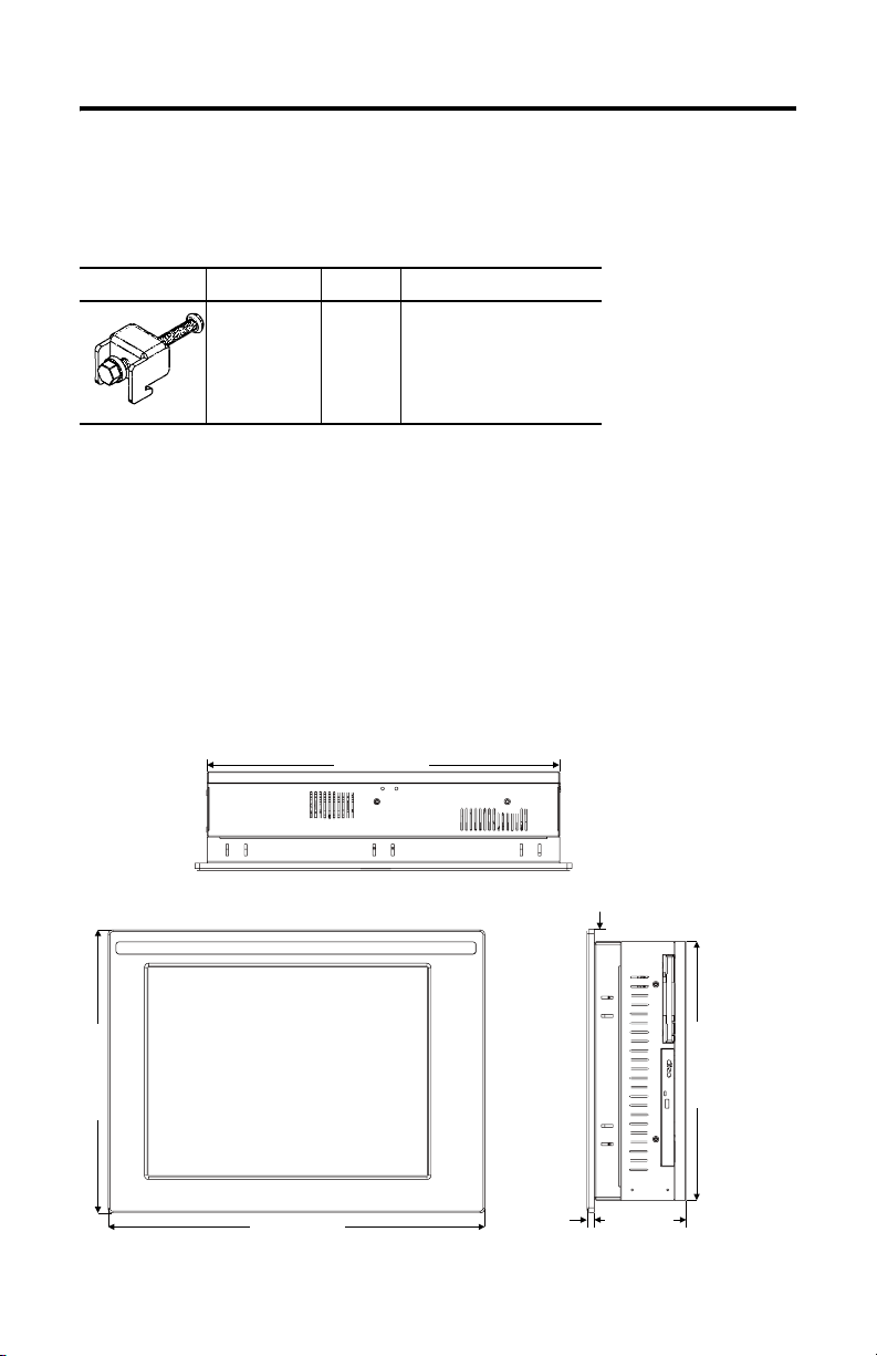
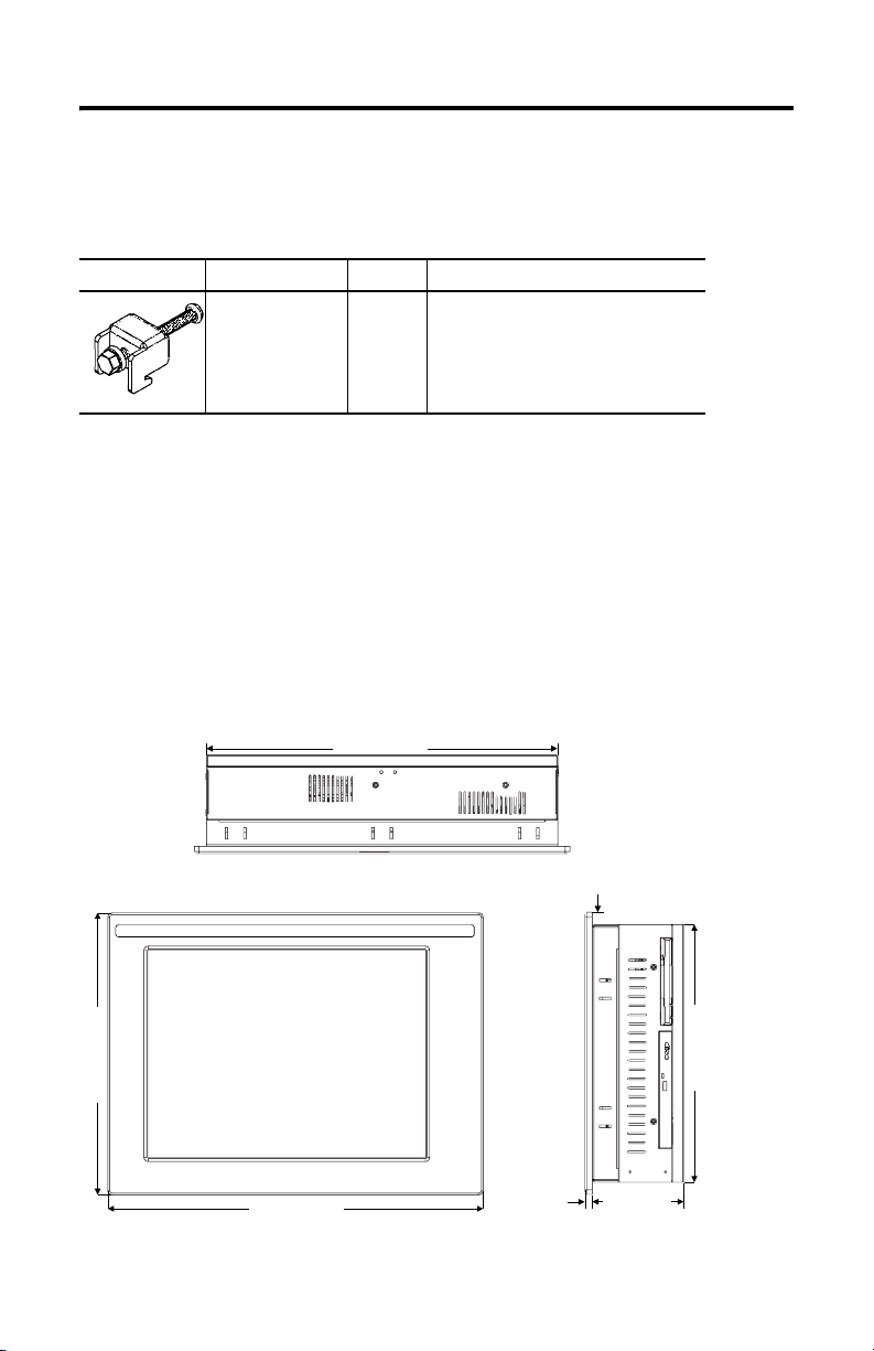
Mounting Dimensions
1500P VersaView Integrated Display Computer
309.00 [12.17]
410.00 [16.14]
Publication 6181H-IN001B-MU-P
383.60 [15.10]
8.00 [0.31]
13.20 [0.52]
282.60 [11.13]
99.9 [3.93]
Page 9
VersaView 6181H Integrated Display Computers 9
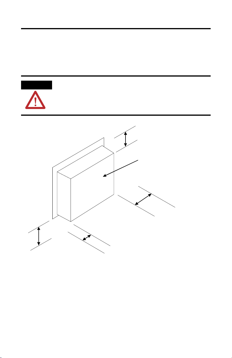
Mounting Clearances
Allow adequate space around the computer for mounting, air flow, and
maintenance. The figure below shows recommended minimum clearances to other
components within the rack or enclosure.
ATTENTION
Bottom Clearance:
102 mm (4 in) for air flow
and connections
Do not operate this computer within a confined space using
clearances that are less than those show below unless
adequate ventilation or other cooling methods are used to
lower the air temperature within the enclosure.
Top Clearance:
50 mm (2 in) for air flow
Back Clearance
25 mm (1 in)
Left Side Clearance:
50 mm (2 in) for air flow
Right Side Clearance:
127 mm (5 in) for air flow,
floppy drive access, and
DVD-ROM or CD-RW access
Publication 6181H-IN001B-MU-P
Page 10

10 VersaView 6181H Integrated Display Computers
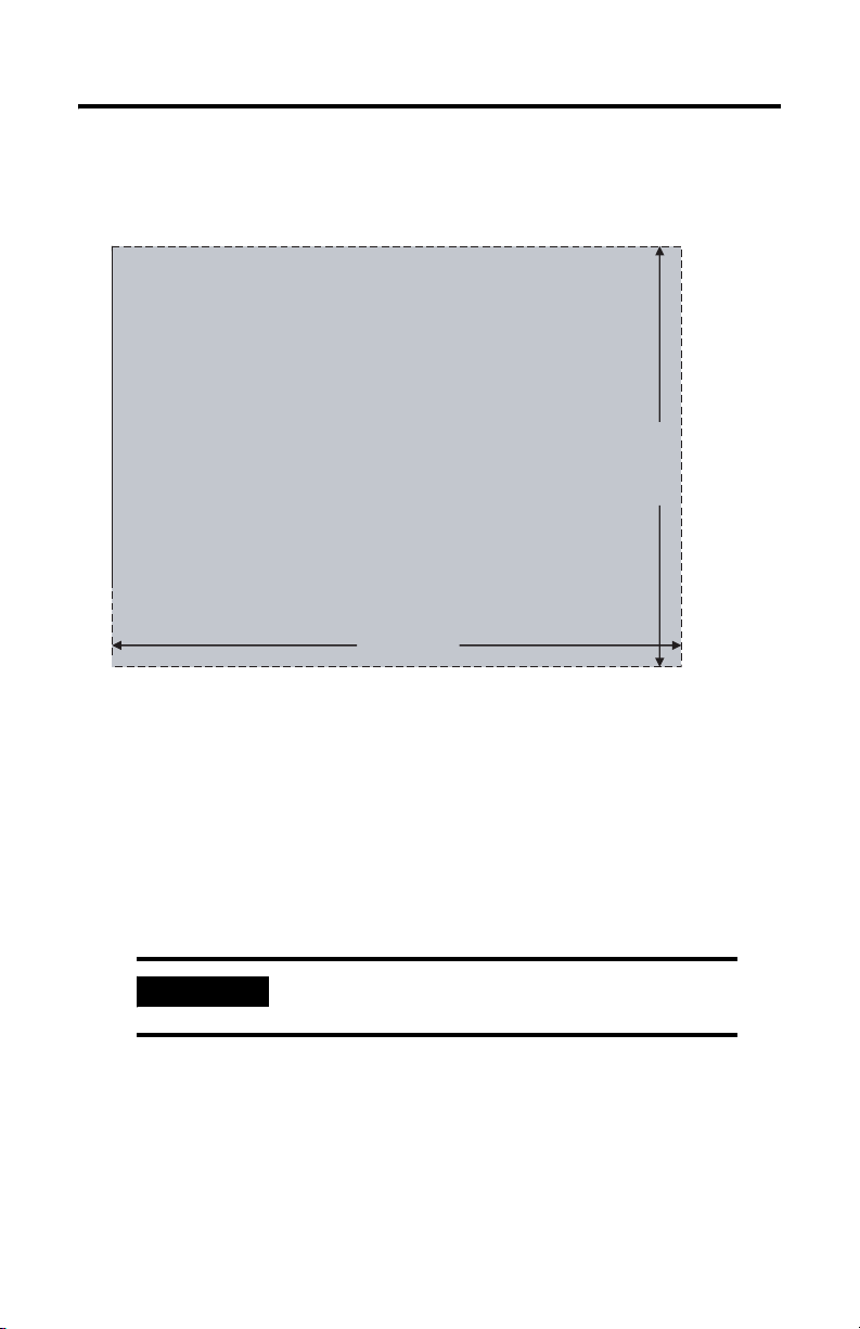
Panel Cutout Dimensions
VersaView 1500P Integrated Display Computer
386.60 [15.22]
285.0 [11.24]
Panel Mounting Guidelines
Observe the following precautions when installing the computer in a panel:
• Confirm that there is adequate space behind the panel. A cabinet with a
minimum depth of 127 mm (5.0 in) is sufficient.
• Supporting panels should be at least 14 gauge to ensure proper sealing
against water and dust and to provide proper support. The mounting
hardware supplied accommodates panels up to 6 mm (0.24 in) thick.
IMPORTANT
Publication 6181H-IN001B-MU-P
Supporting panels must be cut to specifications
before installation.
Page 11
VersaView 6181H Integrated Display Computers 11
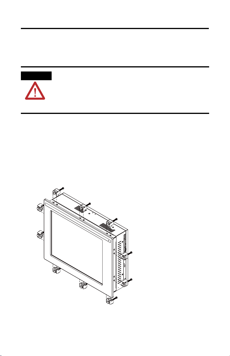
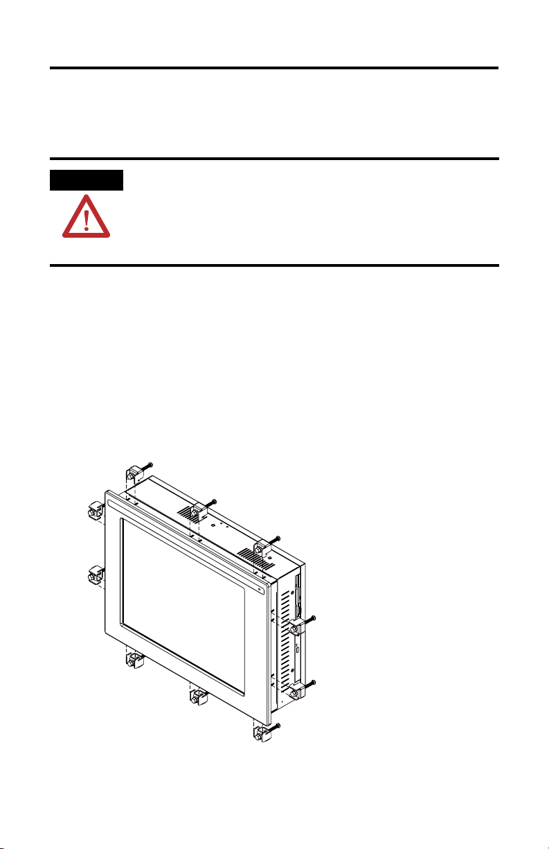
Installing Computer in Panel
To install the computer in a panel using mounting clips:
ATTENTION
1. Cut an opening in the panel using the appropriate panel cutout dimensions.
2. Make sure the sealing gasket is properly positioned on the computer. This
gasket forms a compression type seal, do not use sealing compounds.
3. Place the computer in the panel cutout.
4. Install the mounting clips. The mounting clips slide into the slots on the top,
bottom and sides of the computer.
Disconnect all electrical power from the panel before making
cutout. Make sure the area around the panel cutout is clear. Take
precautions so that metal cuttings do not enter any components
that are already installed in the panel. Failure to follow these
warnings may result in personal injury or damage to the panel
components.
Publication 6181H-IN001B-MU-P
Page 12
12 VersaView 6181H Integrated Display Computers
5. Gradually tighten the clips one at a time around the bezel using the specified
sequence. Note that the sequence begins with the center clips and continues
to the corner clips.
1109
5
Tor qu e
Sequence
4
3
6
278
Repeat this process at least three times until the clips are hand-tight and the
gasket is compressed uniformly against the panel.
6. Tighten mounting clips to a torque of 10 in-lbs (1.1 N•m) in the sequence
shown above. Do not over-tighten.
ATTENTION
Tighten mounting clips to a torque of 10 in-lbs (1.1
N•m) to provide a proper seal and prevent damage to
the computer. Rockwell Automation assumes no
responsibility for water or chemical damage to the
terminal or other equipment within the enclosure
because of improper installation.
Publication 6181H-IN001B-MU-P
Page 13
VersaView 6181H Integrated Display Computers 13
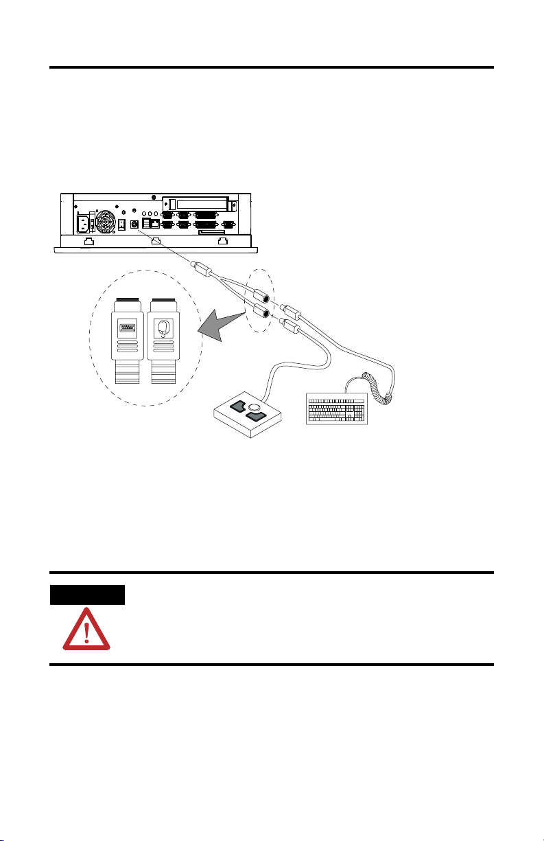
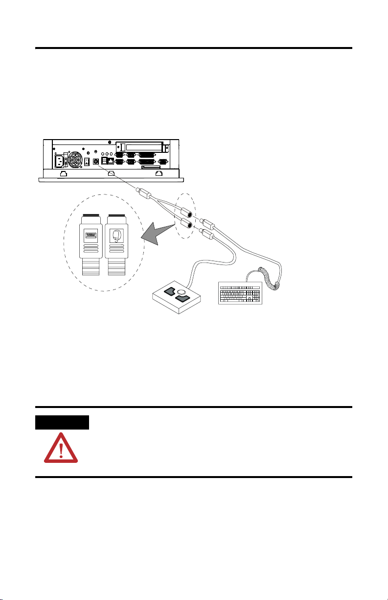
Connecting a Keyboard and Pointing Device
A keyboard can be plugged individually into the PS2 port on the bottom of the
computer. A keyboard and pointing device can be plugged together into this port
using a wye adapter (included).
Connecting Peripheral Devices
• When connecting peripheral devices to the COM, Printer, or VGA ports on
the unit, secure the connected devices with screws.
• When connecting a LAN cable, make sure the cable is fully inserted and the
latch engaged.
WARNING
• When connecting PS2 or USB devices, adhere to the control drawing
information starting on page 14.
When connecting a LAN cable, make sure the cable is fully inserted and the latch engaged. Failure to do so, could result in
an electrical arc. This could cause an explosion in a hazardous
location.
Publication 6181H-IN001B-MU-P
Page 14
14 VersaView 6181H Integrated Display Computers
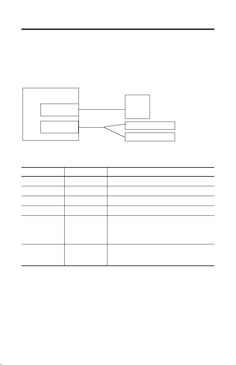
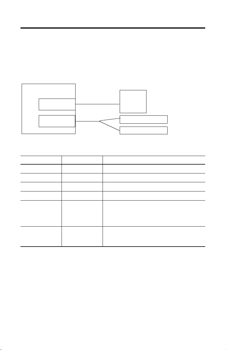
VersaView 1500P Control Drawing
The following control drawing is provided in accordance with the National
Electrical Code, Article 500 (Class I, Zone 2, Group IIB and Class I, Division 2,
Group C and D).
Associated Nonincendive
Field Wiring Apparatus
VersaView 1500P Host Product
USB Ports
(2 provided)
Nonincendive
Field Wiring Apparatus
USB
Peripheral
Device(s)
PS2 Port
Supplied
Y Cable
PS2 Peripheral Device
PS2 Peripheral Device
Table 1 VersaView 1500P USB and PS2 Port Circuit Parameters
Parameter Value Parameter Definition
V
oc (USB)
I
sc (USB)
V
oc (PS2)
I
sc (PS2)
C
a
L
a
5.25V dc Open circuit voltage of each host USB port.
2.2 A Maximum output current of each host USB port.
5.25V dc Open circuit voltage of the host PS2 port.
2.2 A Maximum output current of the host PS2 port.
30 µF The Ca is the maximum total capacitance that can be
connected to any or all ports. If multiple peripheral devices
are used, the total capacitance of all devices and their
cables must not exceed the C
1.7 µH The total inductance that can be connected to any single
port. The total inductance of each device and its cable must
not exceed the L
value.
a
value.
a
Publication 6181H-IN001B-MU-P
Page 15
VersaView 6181H Integrated Display Computers 15
Table 2 Required Circuit Parameters for USB and PS2 Peripheral Devices
Parameter Value Parameter Definition
V
max
5.25V dc
(minimum)
I
max
2.2 A
(minimum)
C
i
L
i
30 µF Maximum allowed total capacitance of all peripheral devices and their
1.7 µH Maximum allowed total inductance of each peripheral device and its
Maximum applied voltage rating of each peripheral device. V
peripheral shall be greater than or equal to V
V
max (per ipheral)
≥ V
oc (USB)
and/or V
oc (PS2)
and V
oc (USB)
as appropriate
oc (PS2)
of each
max
in Table 1.
Maximum current to which each peripheral device can be subjected. I
each peripheral shall be greater than or equal to I
I
max (peripheral)
≥ I
associated cables. The sum of C
devices and C
(C
i + Ccable)USB1
cable
associated cable. The sum of C
sc (USB)
and/or I
as appropriate
sc (PS2)
of all simultaneously connected peripheral
i
of their associated cables sh all be less than or equal to Ca.
+ (Ci + C
+ (Ci + C
cable)USB2
of each peripheral device and L
L
cable)PS2
associated cables shall be less than or equal to L
+ L
(L
i
(Li + L
(Li + L
cable) USB1
cable) USB2
cable) PS2
≤ L
≤ L
≤ L
a
a
a
sc (USB)
≤ C
.
a
and I
a
sc (PS2)
in Table 1.
cable
max
of its
of
Application Information
Per the National Electrical Code, the circuit parameters of associated field wired
apparatus for use in hazardous locations shall be coordinated with the host product
such that their combination remains nonincendive. The VersaView 1500P computer,
and the USB, and PS2 peripheral devices shall be treated in this manner.
The circuit parameters of the VersaView 1500P computer’s USB and PS2 ports are
given in Table 1. The VersaView 1500P computer provides two USB ports and one
PS2 port with a Y-cable.
The USB and PS2 peripheral devices and their associated cabling shall have circuit
parameters with the limits given in Table 2 for them to remain nonincendive when
used with the computer’s USB and PS2 ports. For the comparison of C
and Ci, use
a
the sum of the capacitance of all connected peripheral devices and their associated
cables C
peripheral device and its associated cable for L
. For the comparison of La and Li, use the inductance of each individual
i
.
i
If cable compliance and inductance are not known, the following values from UL
913 may be used:
= 60 pF/ft
C
cable
L
= 0.20 µH/ft
cable
Publication 6181H-IN001B-MU-P
Page 16
16 VersaView 6181H Integrated Display Computers
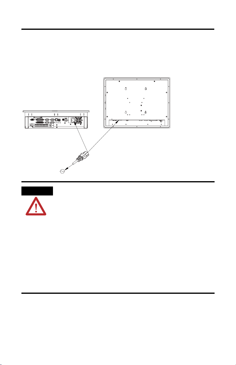
Power Connections
A standard IEC 320 power cord provides power to the computer. The power supply
input will accept 120/240V AC. The power supply is autoswitching. Ensure that
sufficient power is available at the site.
ATTENTION
Publication 6181H-IN001B-MU-P
Select an electrical source carefully before plugging in your
computer:
• The power cord must be connected to a source having an
earth ground. Failure to follow this warning could result in
severe electrical shock.
• The source you select should have its own disconnect. Do not
connect the computer into a source that is connected to the
main electrical disconnect.
• To prevent problems resulting from power surges or
unexpected power failure, you should protect the source with
its own fuses or circuit breakers, as well as an Uninterruptible
Power Supply (UPS) system.
• Always shut down the operating system prior to removing
power. Failure to do so will cause performance degradation
and eventual failures in the operating system
Page 17
VersaView 6181H Integrated Display Computers 17
Network Connections
VersaView computers accommodate CAT5 twisted pair Ethernet cabling with RJ45
connectors to support 100 Mbps network data transfer.
IMPORTANT
Performance degradation of your Ethernet communications is
likely to result if the unit or cables are subjected to extreme
radiated or conducted high-frequency noise. It is the user’s
responsibility to properly route cables and condition input power
in order to improve communication reliability.
Proper cable routing and power conditioning is required to ensure
reliable Ethernet communications in industrial environments.
Rockwell Automation recommends that all Ethernet cabling be
routed through dedicated metal conduits. Installing ferrite bead
filters at cable ends may also improve reliability.
Battery Information
The computer contains a battery to maintain CMOS settings and the real-time clock.
The battery is located in a battery holder on the computer’s motherboard.
WARNING
Do not dispose of battery in a fire or incinerator. Dispose of
used batteries in accordance with local regulations or manufacturer’s instructions.
Specifications
Specifications
Display
Display Description Active Matrix Color TFT
Display Size 15.0 inch
Display Area 305 x 229 mm (12 x 9 in)
Resolution 1024 x 768, 256K Color
Response Time 15 ms (typical)
Touchscreen (optional) Resistive antiglare
Publication 6181H-IN001B-MU-P
Page 18

18 VersaView 6181H Integrated Display Computers
Specifications
Mechanical
Weight 10 kg (23 lb)
Dimensions, Overall (H x W x D) 309 x 410 x 109 mm (12.17 x 6.14 x 4.29 in)
Cutout Dimensions (H x W) 285 x 386.6 mm (11.24 x 15.22 in)
Environmental
Operating Temperature 0…50 °C (32…122 °F)
Storage Temperature -20…60 °C (-4 to 140 °F)
Relative Humidity 10%…90% without condensation
Shock, Operating 15 g (1/2 sine, 11ms)
Shock, Non-operating 30 g (1/2 sine, 11ms)
Vibration, Operating 1 g Peak (10…500Hz)
Vibration, Non-operating 2 g Peak (10…500Hz)
Electrical
Input Voltage, AC 90…264V ac, autoranging
Line Frequency 47…63 Hz
Power Consumption, AC 100 VA (1.0 A @ 100V rms, 0.42 A @ 240 V rms)
Agency Certifications
CE marked for all applicable directives
UL 60079-15 Recognized Component, C-UL
Certified
LVD (73/23/EEC)
EMC (89/336/EEC)
C-Tick
I, Division 2, Class I, Zone 2
Class
Publication 6181H-IN001B-MU-P
Page 19

Notice d'installation
Panel PC VersaView 6181H
Référence 6181H-15xxxxxxx
Français
Pour de plus amples informations sur les Panel PC VersaView, reportez-vous à la
publication 6181P-UM001. Vous pouvez charger une version électronique gratuite de
cette publication sur les sites Internet :
• http://support.rockwellautomation.com
Sommaire...
Avant de déballer le Panel PC ................................................................................................. 20
Expédition/transport du PanelPC ............................................................................................ 20
Conformité aux directives de l'Union européenne .................................................................. 21
Environnements dangereux ..................................................................................................... 21
Environnement ......................................................................................................................... 23
Matériel de montage ............................................................................................................... 24
Outils nécessaires .................................................................................................................... 24
Dimensions de montage .......................................................................................................... 24
Dégagements ........................................................................................................................... 25
Découpes pour le montage ...................................................................................................... 26
Instructions de montage sur panneau ..................................................................................... 26
Installation du Panel PC sur un panneau ................................................................................. 27
Connexion d'un clavier et d'un dispositif de pointage ............................................................ 29
Schéma de commande du VersaView 1500P .......................................................................... 30
Alimentation électrique ........................................................................................................... 32
Connexions réseau ................................................................................................................... 33
Informations concernant la pile ............................................................................................... 33
Caractéristiques ....................................................................................................................... 34
Publication 6181H-IN001B-MU-P
Page 20
20 Panel PC VersaView 6181H
Avant de déballer le Panel PC
Avant de déballer votre nouveau Panel PC, vérifiez que l'emballage est en bon état. S'il
est endommagé, contactez immédiatement l'expéditeur et demandez une assistance.
Autrement, déballez votre Panel PC.
CONSEIL
Conservez l'emballage d'origine complet du Panel PC au cas où
vous devriez le renvoyer pour réparation. Les cartons d'emballage
interne et externe sont nécessaires pour protéger efficacement les
équipements renvoyés pour réparation.
Expédition/transport du Panel PC
Si vous devez expédier votre Panel PC par transporteur ou le transporter sur un autre
site, vous devez d'abord l'extraire du panneau sur lequel il est installé et le placer dans
son emballage d'origine.
ATTENTION
Vous ne devez en aucun cas expédier ou transporter le Panel PC
monté sur une porte ou un panneau. Vous devez l'extraire du
panneau et le placer dans son emballage d'origine avant de l'expédier
ou de le transporter. Si vous le transportez sans le retirer du panneau
ou de la porte sur lequel où il est installé, vous risquez de
l'endommager de façon importante. Rockwell Automation ne peut
être tenu pour responsable des dommages causés au Panel PC s'il a
été expédié ou transporté alors qu'il était installé sur une porte ou un
panneau.
Publication 6181H-IN001B-MU-P
Page 21
Panel PC VersaView 6181H 21
Conformité aux directives de l'Union européenne
Ce Panel PC est conforme aux directives de l'Union européenne lorsqu'il est installé
dans les pays de l'Union européenne et de l'Espace Economique Européen et porte le
marquage CE. Une copie de la déclaration de conformité peut être consultée sur le site
Internet de Rockwell Automation http://support.rockwellautomation.com, sous la
rubrique Product Certification, consacrée à la certification des produits.
ATTENTION
ATTENTION
Ce Panel PC est conçu pour être utilisé en milieu industriel ou dans
une salle de commande, dans lesquels l'alimentation est isolée des
sources basse tension du secteur. Certaines installations peuvent ne
pas être conformes à la norme EN 61000-3-2 (Emissions de courant
harmonique), telle que spécifiée par la directive CEM de l'Union
européenne. Vous devez obtenir une autorisation des autorités locales
avant de connecter tout système consommant plus de 75 watts
directement à partir du secteur.
Pour être conforme à la norme EN 55024, la longueur du câble réseau
Ethernet ne doit pas excéder 30 m et ce dernier ne doit être utilisé
qu'à l'intérieur (il ne doit pas sortir du bâtiment sur toute sa
longueur). La longueur de tous les autres câbles d'E/S ne doit pas être
supérieure à 3 m et ces derniers ne doivent être utilisés qu'à
l'intérieur.
Environnements dangereux
Cet équipement peut être utilisé dans les environnements suivants :
• environnements dangereux de Classe I, Zone 2, Groupe IIB, code de
température T3 (200 °C) ;
• environnements dangereux de Classe I, Division 2, Groupes C et D, code de
température T3C (160 °C) ;
• ou environnements non dangereux.
La mise en garde suivante s'applique à une utilisation en environnement dangereux.
AVERTISSEMENT
Danger d'explosion
• La substitution de composants peut rendre cet équipement
impropre à une utilisation en environnement dangereux.
• Ne pas déconnecter l'équipement sans s'être assuré que
l'alimentation est coupée ou que l'environnement est classé
non dangereux.
• Ne pas connecter ou déconnecter des composants sans s'être
assuré que l'alimentation est coupée.
• L’ensemble du câblage doit être conforme à la réglementation
en vigueur dans le pays où cet équipement est installé.
• L’équipement périphérique doit être adapté à
l’environnement dans lequel il est utilisé.
Les codes de température indiqués ci-dessus reposent sur une température de
fonctionnement du Panel PC de 50 °C. N'installez pas le Panel PC dans une atmosphère
explosive (gaz, poussière, fibres) dont la température d'ignition est inférieure à la
température indiquée.
Publication 6181H-IN001B-MU-P
Page 22

22 Panel PC VersaView 6181H
Armoires de protection
Montez le Panel PC sur un panneau ou dans une armoire pour en protéger les circuits
internes. Les versions avec face avant étanche sont conformes à la classe de protection
CEI IP66 uniquement lorsqu'elles sont montées sur un panneau ou dans une armoire
ayant une classe de protection équivalente.
ATTENTION
Environnement et armoires de protection
Cet équipement est prévu pour fonctionner en environnement industriel
avec une pollution de niveau 2, dans des applications de surtension de
catégorie II (telles que définies dans la publication 60664-1 de la CEI) et
à une altitude maximum de 2000 m sans déclassement.
Cet équipement fait partie des équipements industriels de Groupe 1,
Classe A selon la publication 11 de la CEI/CISPR. A défaut de
précautions suffisantes, il se peut que la compatibilité électromagnétique
ne soit pas garantie dans les autres environnements, en raison des
perturbations par conduction et par rayonnement.
Cet équipement est fourni en tant qu'équipement de type « ouvert ». Il
doit être installé à l'intérieur d'une armoire fournissant une protection
adaptée aux conditions d'utilisation ambiantes et suffisante pour éviter
tout risque de blessure corporelle pouvant résulter d'un contact direct
avec des composants sous tension. L'accès à l'intérieur de l'armoire ne
doit être possible qu'à l'aide d'un outil. Certaines sections de la présente
publication peuvent comporter des recommandations supplémentaires
portant sur les degrés de protection spécifiques à respecter pour
maintenir la conformité à certaines normes de sécurité.
Reportez-vous à la publication NEMA 250 ou à la publication 60529 de la
CEI, selon le cas, pour obtenir une description des degrés de protection
que procurent les différents types d'armoires. Consultez également les
sections appropriées de la présente publication, ainsi que les Directives
de câblage et de mise à la terre pour automatisation industrielle
(publication Allen-Bradley 1770-4.1FR) pour toute information
supplémentaire sur les conditions d'installation requises pour cet
équipement.
Publication 6181H-IN001B-MU-P
Page 23

Panel PC VersaView 6181H 23
Environnement
Observez les directives suivantes pour assurer le bon fonctionnement du Panel PC, en
toute sécurité.
• Vérifiez qu'il y a suffisamment d'espace disponible autour des prises d'air et des
orifices d'aération pour permettre la circulation d’air nécessaire au
refroidissement. Veillez à ce que ces orifices soient toujours dégagés.
• Dans une armoire, laissez un dégagement suffisant pour maintenir une bonne
ventilation. La température ambiante autour du Panel PC doit être maintenue
entre 0 et 50 °C. Tenez compte également de la chaleur dégagée par les autres
appareils présents dans l'armoire. Vous devrez peut-être utiliser un ventilateur
supplémentaire, un échangeur de chaleur ou un conditionneur d'air pour
répondre à cet impératif dans certaines installations.
CONSEIL
IMPORTANT
• Vérifiez que l'humidité de l'air ambiant ne dépasse pas les limites indiquées.
Dans les environnements très secs, l'électricité statique se forme très facilement.
La mise à la terre correcte de l'équipement par le cordon d'alimentation c.a.
permet de réduire le risque de décharges d'électricité statique, qui peuvent
endommager les composants électroniques.
• Laissez toujours le boîtier ou le capot du Panel PC en place lorsqu'il fonctionne.
Le capot protège des tensions élevées à l'intérieur du Panel PC et empêche les
émissions radioélectriques qui peuvent interférer avec d'autres équipements.
N'oubliez pas que la chaleur monte. La température dans
la partie supérieure d'une armoire est souvent bien plus
élevée que dans le reste de l'armoire si l'air ne circule pas.
Ce Panel PC est conçu pour fonctionner dans des plages de
températures extrêmes. Cependant, il est déconseillé de le
faire fonctionner continuellement à la température maximale
indiquée.
Bien que cet équipement puisse fonctionner à la température
maximale de sa plage de fonctionnement, la durée de vie
générale de tout équipement électronique est raccourcie
lorsqu'il fonctionne à sa température nominale la plus élevée.
Publication 6181H-IN001B-MU-P
Page 24
24 Panel PC VersaView 6181H
Matériel de montage
Le Panel PC est fourni avec le matériel de montage suivant :
Pièce Description Quantité Pour
Supports de fixation 10 Montage sur panneau ou dans une armoire
Outils nécessaires
Outre les outils utilisés pour la découpe, vous aurez besoin de l'outil suivant :
• tournevis Phillips n° 2.
Dimensions de montage
Panel PC VersaView 1500P
309
410
Publication 6181H-IN001B-MU-P
383,6
13,2
282,6
8
99,9
Page 25

Panel PC VersaView 6181H 25
Dégagements
Laissez suffisamment d'espace autour du Panel PC pour le montage, la ventilation et la
maintenance. La figure ci-dessous indique les dégagements minimaux recommandés par
rapport aux autres composants présents dans le rack ou dans l'armoire.
ATTENTION
Dégagement inférieur
de 102 mm pour la ventilation
et les connexions
Ce Panel PC ne doit pas être utilisé dans un espace clos avec des
dégagements inférieurs à ceux indiqués ci-après sans une
ventilation correcte ou tout autre système de refroidissement pour
abaisser la température de l'air à l'intérieur de l'armoire.
Dégagement supérieur
de 50 mm pour la ventilation
Dégagement à l'arrière
de 25 mm
Dégagement de 50 mm sur
le côté gauche pour la
ventilation
Dégagement de 127 mm sur
le côté droit pour la ventilation
et l'accès aux lecteurs de disquette,
de DVD-ROM ou de CD-RW
Publication 6181H-IN001B-MU-P
Page 26
26 Panel PC VersaView 6181H
Découpes pour le montage
Panel PC VersaView 1500P
285
386,6
Instructions de montage sur panneau
Prenez les précautions suivantes lors du montage d'un Panel PC sur un panneau :
• vérifiez qu'il y a un dégagement suffisant derrière le panneau ; une armoire d'au
moins 127 mm de profondeur est suffisante ;
• le panneau supportant le Panel PC doit être de calibre 14 au minimum pour
assurer une bonne étanchéité contre l'eau et la poussière et fournir un support
suffisant. Le matériel de montage fourni permet d'utiliser des panneaux jusqu'à
6 mm d'épaisseur.
IMPORTANT
Publication 6181H-IN001B-MU-P
Les panneaux doivent être découpés aux dimensions
indiquées avant l'installation.
Page 27
Panel PC VersaView 6181H 27
Installation du Panel PC sur un panneau
Pour installer le Panel PC sur un panneau à l'aide de supports de fixation :
ATTENTION
1. Découpez une ouverture dans le panneau en respectant le schéma de découpe
fourni.
2. Vérifiez que le joint d'étanchéité est correctement positionné sur le Panel PC. Ce
joint donne une étanchéité par compression : n'utilisez pas de produit
d'étanchéité.
3. Placez le Panel PC dans la découpe du panneau.
4. Mettez les supports de fixation en place. Ils s'insèrent dans les encoches situées
sur les parties latérales, supérieure et inférieure du Panel PC.
Débranchez toute alimentation électrique du panneau avant de faire
la découpe. Assurez-vous que la zone autour du panneau est
dégagée. Prenez les précautions nécessaires pour qu'aucun copeau
métallique ne pénètre dans les composants déjà installés sur le
panneau. En cas de non-respect de cette consigne, vous risquez de
vous blesser ou d'endommager les composants du panneau.
Publication 6181H-IN001B-MU-P
Page 28
28 Panel PC VersaView 6181H
5. Serrez les supports de fixation à la main progressivement, l'un après l'autre
autour de la face avant, en suivant l'ordre de serrage indiqué ci-dessous.
Remarquez que l'ordre de serrage commence par les supports de fixation du
centre et se poursuit par les supports situés dans les angles.
1109
5
Ordre de
serrage
4
3
6
278
Répétez ce processus au moins trois fois jusqu'à ce que les supports de
fixation soient correctement serrés et que le joint soit comprimé
uniformément contre le panneau.
6. Serrez les supports de fixation avec un couple de serrage de 1,1 Nm dans l'ordre
indiqué précédemment. Veillez à ne pas trop les serrer.
ATTENTION
Serrez les supports de fixation avec un couple de serrage
de 1,1 Nm pour assurer une bonne étanchéité sans
endommager le Panel PC. Rockwell Automation ne saurait
être tenu pour responsable des dégâts causés par une
infiltration d'eau ou de produit chimique dans le Panel PC
ou dans tout autre équipement présent dans l'armoire,
suite à une installation incorrecte.
Publication 6181H-IN001B-MU-P
Page 29
Panel PC VersaView 6181H 29
Connexion d'un clavier et d'un dispositif de pointage
Vous pouvez connecter seulement un clavier au port PS2 situé sous le Panel PC ou
brancher un clavier et un dispositif de pointage ensemble sur ce port à l'aide d'un
adaptateur en Y (fourni).
Connexion de périphériques
• Si vous connectez des périphériques aux ports de communication, d'imprimante
ou VGA du Panel PC, fixez-les à l'aide de vis.
• Si vous connectez un câble réseau, vérifiez qu'il est inséré à fond dans le
connecteur et que le verrou est enclenché.
AVERTISSEMENT
• Si vous connectez des périphériques PS2 ou USB, respectez le schéma de
commande et les informations de la page 30.
Si vous connectez un câble réseau, vérifiez qu'il est inséré à fond
dans le connecteur et que le verrou est enclenché. En cas de
non-respect de cette consigne, un arc électrique risque de se
produire et provoquer une explosion dans un environnement
dangereux.
Publication 6181H-IN001B-MU-P
Page 30
30 Panel PC VersaView 6181H
Schéma de commande du VersaView 1500P
Le schéma suivant est conforme à l'article 500 (environnements de Classe I, Zone 2,
Groupe IIB et de Classe I, Division 2, Groupes C et D) du Code national de l'électricité
des Etats-Unis.
Appareils câblés sur site associés,
non incendiaires
Panel PC hôte VersaView 1500P
Appareils câblés sur site,
non incendiaires
Ports USB
(2 fournis)
Port PS2
Câble en Y
fourni
Périphérique(s)
USB
Périphérique PS2
Périphérique PS2
Tableau 3 Paramètres de circuit des ports USB et PS2 du Panel PC VersaView 1500P
Paramètre Valeur Définition du paramètre
V
co (USB)
I
sc (USB)
V
co (PS2)
I
sc (PS2)
C
a
L
a
5,25 V c.c. Tension en circuit ouvert de chaque port USB hôte.
2,2 A Intensité de sortie maximale de chaque port USB hôte.
5,25 V c.c. Tension en circuit ouvert du port PS2 hôte.
2,2 A Intensité de sortie maximale du port PS2 hôte.
30 µF Ca est la capacitance totale maximum pouvant être connectée à
un port ou à tous les ports. En cas d'utilisation de plusieurs
périphériques, la capacitance totale de tous les périphériques
et de leurs câbles ne doit pas dépasser la valeur C
1,7 µH Inductance totale pouvant être connectée à un seul port.
L'inductance totale d'un périphérique et de son câble ne doit
pas dépasser la valeur L
.
a
.
a
Publication 6181H-IN001B-MU-P
Page 31

Panel PC VersaView 6181H 31
Tableau 4 Paramètres de circuit requis pour les périphériques USB et PS2
Paramètre Valeur Définition du paramètre
V
max
I
max
C
i
L
i
5,25 V c.c.
(minimum)
2,2 A
(minimum)
30 µF Capacitance totale maximum autorisée de chaque périphérique et de ses câbles. La
1,7 µH Inductance totale maximum autorisée de chaque périphérique et de ses câbles. La
Informations d'application
D'après le Code national de l'électricité des Etats-Unis, les paramètres de circuit des
appareils câblés sur site associés, destinés à être utilisés dans des environnements
dangereux, doivent être coordonnés avec le produit hôte, de sorte que l'ensemble reste
non incendiaire. Le Panel PC VersaView 1500P, ainsi que les périphériques USB et PS2,
doivent être conformes à cette règle.
Les paramètres de circuit des ports USB et PS2 du Panel PC VersaView 1500P sont
indiqués dans le tableau 1. Le Panel PC VersaView 1500P comporte deux ports USB et
un port PS2 avec un câble en Y.
Les paramètres de circuit des périphériques USB et PS2, et de leurs câbles, doivent
figurer dans les limites indiquées dans le tableau 2 pour que ces périphériques et ces
câbles restent non incendiaires lorsqu'ils sont connectés aux ports USB et PS2 du
Panel PC. Pour comparer C
connectés et celle de leurs câbles pour C
chaque périphérique et de leurs câbles pour L
Si vous ne connaissez pas l'inductance ni la conformité des câbles, utilisez les valeurs
suivantes, extraites de la norme UL 913 :
= 60 pF/ft (18 pF/m)
C
câble
= 0,20 µH/ft (0,06 µH/m)
L
câble
Tension nominale appliquée maximale de chaque périphérique. La valeur V
chaque périphérique doit être supérieure ou égale aux valeurs V
co (USB)
et V
max
co (PS2)
indiquées dans le tableau 1.
V
max (périphérique)
≥ V
co (USB)
et/ou V
co (PS2)
selon le cas
Intensité maximale à laquelle chaque périphérique peut être soumis. La valeur I
de chaque périphérique doit être supérieure ou égale aux valeurs I
sc (USB) et Isc (PS2)
indiquées dans le tableau 1.
≥ I
I
max (périphérique)
somme de C
de tous les périphériques connectés en même temps et de C
i
sc (USB)
et/ou I
leurs câbles doit être inférieure ou égale à C
(C
i+Ccâble)USB1
somme de C
ou égale à L
(L
+ L
i
(Li+ L
(Li+ L
a
+(Ci+C
câble)USB2
de chaque périphérique et de L
L
.
a
≤ L
câble)USB1
câble)USB2
câble)PS2
≤ L
≤ L
a
a
a
et Ci, additionnez la capacitance de tous les périphériques
. Pour comparer La et Li, utilisez l'inductance de
i
i
.
sc (PS2)
+(Ci+C
selon le cas
.
a
≤ C
câble)PS2
a
de ses câbles doit être inférieure
câble
câble
de
max
de
Publication 6181H-IN001B-MU-P
Page 32

32 Panel PC VersaView 6181H
Alimentation électrique
Le Panel PC s'utilise avec un cordon d'alimentation standard CEI 320. L'entrée
d'alimentation accepte des tensions de 120/240 V c.a. L'alimentation est auto-adaptative.
Vérifiez que l'alimentation sur votre site est suffisante.
ATTENTION
Soyez vigilant quant au choix de la prise de courant sur laquelle vous
allez brancher le Panel PC :
• le cordon d'alimentation doit être branché sur une prise de terre.
En cas de non-respect de cette consigne, vous risquez de vous
électrocuter ;
• la prise sélectionnée doit comporter son propre sectionneur. Ne
branchez pas le Panel PC sur une prise connectée au disjoncteur
principal ;
• pour éviter tout problème de surtension ou de coupure de
courant inopinée, protégez la prise avec ses propres fusibles ou
disjoncteurs et avec un système d'alimentation sans coupure
(onduleur UPS) ;
• arrêtez toujours le système avant de déconnecter l'alimentation.
le non-respect de cette consigne entraîne une dégradation des
performances et risque de causer des défaillances au niveau du
système d'exploitation.
Publication 6181H-IN001B-MU-P
Page 33

Panel PC VersaView 6181H 33
Connexions réseau
Les Panel PC VersaView acceptent les câbles Ethernet CAT5 à paire torsadée avec
connecteurs RJ45 pour les transferts réseau à 100 Mb/s.
IMPORTANT
L'exposition de l'unité ou des câbles à de fortes perturbations par
rayonnement ou par conduction risque de dégrader les performances
de vos communications Ethernet. L'utilisateur est responsable de
l'acheminement correct des câbles et du conditionnement adéquat de
l'alimentation pour améliorer la fiabilité des communications.
Un acheminement correct des câbles et un bon conditionnement de
l'alimentation sont nécessaires pour assurer des communications
Ethernet fiables en milieu industriel. Rockwell Automation
recommande d'acheminer tous le câblage Ethernet dans des gaines
métalliques dédiées. L'installation de perles de ferrite aux extrémités
des câbles peut également améliorer la fiabilité.
Informations concernant la pile
Le Panel PC contient une pile qui conserve la mémoire CMOS et l'horloge temps réel.
Cette pile se trouve dans un compartiment situé sur la carte mère du Panel PC.
AVERTISSEMENT
Ne jetez pas la pile dans le feu ou dans un incinérateur.
Conformez-vous aux réglementations locales en vigueur ou aux
directives du fabricant pour mettre les piles au rebut.
Publication 6181H-IN001B-MU-P
Page 34

34 Panel PC VersaView 6181H
Caractéristiques
Caractéristiques
Affichage
Description de l'écran TFT couleur à matrice active
Taille de l'écran 15,0 pouces
Surface d'affichage 305 x 229 mm
Résolution 1024 x 768, couleurs 256K
Temps de réponse 15 ms (type)
Dalle tactile (en option) Analogique résistive
Caractéristiques physiques
Poids 10 kg
Dimensions hors-tout (H x L x P) 309 x 410 x 109 mm
Dimensions de découpe (H x L) 285 x 386 mm
Environnement
Température de fonctionnement 0 à 50 °C
Température de stockage -20 à 60 °C
Humidité relative 10 à 90 % sans condensation
Tenue aux chocs en fonctionnement 15 g (1/2 sinusoïdale, 11ms)
Tenue aux chocs hors fonctionnement 30 g (1/2 sinusoïdale, 11ms)
Résistance aux vibrations en fonctionnement Pic de 1 G (de 10 à 500 Hz)
Résistance aux vibrations hors fonctionnement Pic de 2 G (de 10 à 500Hz)
Caractéristiques électriques
Tension d'alimentation c.a. 90 à 264 V c.a., auto-adaptative
Fréquence de ligne 47 à 63 Hz
Consommation électrique (c.a.) 100 VA (1 A à 100 V efficaces, 0,42 A à 240 V efficaces)
Publication 6181H-IN001B-MU-P
Page 35

Caractéristiques
Homologations
Marqué CE pour toutes les directives en vigueur
Composant reconnu par la norme UL 60079-15,
certifiéC-UL
Directive Basse Tension de la Communauté
européenne (73/23/EEC)
Directive CEM de la Communauté européenne
(89/336/EEC)
C-Tick
Classe
I, Division 2, Classe I, Zone 2
Panel PC VersaView 6181H 35
Publication 6181H-IN001B-MU-P
Page 36

36 Panel PC VersaView 6181H
Publication 6181H-IN001B-MU-P
Page 37

Installationsanleitung
VersaView-Computer 6181H mit integrierter
Anzeige
Bestellnummer 6181H-15xxxxxxx
Deutsch
Weitere Informationen zu VersaView-Computern mit integrierter Anzeige finden Sie in
der Publikation 6181P-UM001. Eine elektronische Version dieser Publikation kann
kostenlos unter folgender Adresse heruntergeladen werden:
• http://support.rockwellautomation.com.
Inhalt
Vor dem Auspacken des Computers ................................................................................ 38
Auspacken/Transport des Computers .............................................................................. 38
EU-Richtlinien .................................................................................................................. 39
Explosionsgefährdete Standorte ..................................................................................... 39
Hinweise zu den Umgebungsbedingungen ..................................................................... 41
Montagezubehör .............................................................................................................. 42
Erforderliche Werkzeuge .................................................................................................. 42
Einbaumaße ..................................................................................................................... 42
Montageabstände ............................................................................................................ 43
Ausschnittmaße für den Schaltschrank ........................................................................... 44
Richtlinien für den Einbau in einen Schaltschrank .......................................................... 44
Einbau des Computers in einen Schaltschrank ............................................................... 45
Anschließen einer Tastatur und eines Zeigegeräts ......................................................... 47
VersaView 1500P-Anschlussplan .................................................................................... 48
Spannungsversorgung ..................................................................................................... 50
Netzwerkverbindungen .................................................................................................... 51
Batterieinformationen ...................................................................................................... 51
Technische Daten ............................................................................................................. 51
Publikation 6181H-IN001B-MU-P
Page 38

38 VersaView-Computer 6181H mit integrierter Anzeige
Vor dem Auspacken des Computers
Bevor Sie Ihren neuen Computer auspacken, untersuchen Sie die Originalverpackung
auf Schäden. Bei offensichtlichen Schäden informieren Sie sofort das
Transportunternehmen und fordern Unterstützung an. Andernfalls fahren Sie mit dem
Auspacken fort.
TIPP
Bewahren Sie alle Teile der Originalverpackung des Computers für
den Fall auf, dass Sie diesen einmal zur Reparatur einsenden müssen.
Es müssen die inneren und äußeren Verpackungskartons verwendet
werden, um einen ausreichenden Schutz für alle zur Reparatur
eingesendeten Einheiten zu gewährleisten.
Auspacken/Transport des Computers
Wenn Sie den Computer mit einem herkömmlichen Transportunternehmen oder auf
andere Weise an einen anderen Standort transportieren möchten, müssen Sie diesen
zunächst aus dem Schaltschrank ausbauen und mit den Originalmaterialien verpacken.
ACHTUNG
Versenden oder transportieren Sie den Computer nicht, während dieser in
einer Tür oder einem Schaltschrank eingebaut ist. Sie müssen den
Computer zunächst ausbauen und vor dem Versand oder Transport mit
den Originalmaterialien verpacken. Wenn Sie den Computer in
eingebautem Zustand versenden oder transportieren, können die Geräte
ernsthaft beschädigt werden. Rockwell Automation übernimmt keine
Haftung für Schäden an einem Computer, der in eingebautem Zustand
versandt oder transportiert wurde.
Publikation 6181H-IN001B-MU-P
Page 39

VersaView-Computer 6181H mit integrierter Anzeige 39
EU-Richtlinien
Wenn dieser Computer innerhalb der Europäischen Union oder EWR-Regionen installiert
wird und mit dem CE-Zeichen versehen ist, entspricht er den EU-Richtlinien. Eine Kopie
der Konformitätserklärung steht auf der Website von Rockwell Automation zur
Verfügung: siehe den Link "Product Certification" unter
http://support.rockwellautomation.com.
ACHTUNG
ACHTUNG
Dieser Computer ist für den Betrieb in einer industriellen Umgebung bzw. in
einem Steuerraum vorgesehen, wo bereits eine gewisse Art der Trennung vom
öffentlichen Spannungsnetz verwendet wird. Einige Computer entsprechen
eventuell nicht dem Standard EN 61000-3-2 zu Oberschwingungsströmen, wie
durch die EMV-Richtlinie der Europäischen Union festgelegt. Daher müssen Sie
vor dem Anschließen einer Konfiguration mit einer Leistungsaufnahme von
über 75 Watt AC-Leistung direkt über das öffentliche Stromnetz zunächst die
Erlaubnis des lokalen Stromversorgers einholen.
Für eine Übereinstimmung mit der Richtlinie EN 55024 muss das
Ethernet-LAN-Kabel kürzer als 30 m sein und darf nur in Innenräumen
verwendet werden (d. h. das Gebäude an keinem Punkt verlassen). Alle
anderen E/A-Kabel müssen kürzer als 3 m sein und dürfen nur in Innenräumen
verwendet werden.
Explosionsgefährdete Standorte
Dieses Gerät ist für den Einsatz an folgenden Standorten geeignet:
• Klasse I, Zone 2, Gruppe IIB, T3 Temperaturcode (200 °C)
• Klasse I, Division 2, Gruppe C, D, T3C Temperaturcode (160 °C)
• oder an nicht explosionsgefährdeten Standorten
Folgende Hinweise sind bei einer Installation an explosionsgefährdeten Standorten zu
beachten.
WARNUNG
Explosionsgefahr
• Der Austausch einzelner Komponenten kann die Eignung des Geräts
für explosionsgefährdete Standorte beeinträchtigen.
• Geräte dürfen nur dann abgeklemmt werden, wenn die
Stromversorgung unterbrochen wurde und der Bereich als nicht
explosionsgefährdet eingestuft ist.
• Schließen Sie keine Komponenten an oder entfernen Sie diese,
solange das Gerät mit Strom versorgt wird.
• Die Verdrahtung muss stets gemäß den N.E.C.-Artikeln 501-4(b),
505-15(c) vorgenommen werden.
• Peripheriegeräte müssen für die Verwendung an dem vorgesehenen
Standort zugelassen sein.
Die Angaben zu Temperaturcodes basieren auf der Betriebsumgebungstemperatur des
Computers von 50 °C. Installieren Sie den Computer nicht in Umgebungen mit einer
explosiven Atmosphäre (Gas, Staub, Fasern), die eine Zündtemperatur aufweist, die
unter der angegebenen Temperatur liegt.
Publikation 6181H-IN001B-MU-P
Page 40

40 VersaView-Computer 6181H mit integrierter Anzeige
Gehäuse
Montieren Sie den Computer in einem Schaltschrank oder einem Gehäuse, um die
internen Schaltungen zu schützen. Ausführungen mit einer Dichtungsblende
entsprechen nur dann IEC IP66, wenn sie in einem Schaltschrank oder Gehäuse mit der
gleichen Schutzart montiert werden.
ACHTUNG
Umgebung und Gehäuse
Dieses Gerät ist für den Einsatz in einer industriellen Umgebung mit
einer Verschmutzung des Grades 2, in Anwendungen mit
Überspannungskatekorie II (gemäß IEC-Publikation 60664-1) und in
Höhen von bis zu 2000 m ohne Minderung der Betriebswerte
vorgesehen.
Das Gerät gehört gemäß der IEC/CISPR-Publikation 11 zu
industriellen Geräten der Gruppe 1, Klasse A. Ohne geeignete
Vorsichtsmaßnahmen kann die elektromagnetische Verträglichkeit in
anderen Umgebungen aufgrund der leitungsgeführten und
abgestrahlten Störungen eventuell nicht gewährleistet werden.
Dieses Gerät wird als „offenes” Gerät zur Verfügung gestellt. Es muss
in ein Gehäuse eingebaut werden, das für diese speziellen
Umgebungsbedingungen zugelassen ist und den Zugriff auf leitfähige
Teile und damit das Risiko von Verletzungen verhindert. Der Zugriff
auf das Innere des Gehäuses darf nur mit Hilfe eines Werkzeugs
möglich sein. Die nachfolgenden Abschnitte dieser Publikation
können zusätzliche Informationen über bestimmte Gehäusetypen
enthalten, die mit bestimmten Produktsicherheitszertifizierungen
übereinstimmen müssen.
Die NEMA-Publikation 250 zu den geltenden Standards sowie die
IEC-Publikation 60529 enthalten Erklärungen zu den Schutzgraden,
die durch die verschiedenen Gerätetypen gewährleistet werden.
Weitere Anforderungen zur Installation dieser Geräte enthalten die
entsprechenden Abschnitte dieser Publikation sowie die
Allen-Bradley-Publikation 1770-4.1DE („Richtlinien zur störungsfreien
Verdrahtung und Erdung von industriellen
Automatisierungssystemen”).
Publikation 6181H-IN001B-MU-P
Page 41

VersaView-Computer 6181H mit integrierter Anzeige 41
Hinweise zu den Umgebungsbedingungen
Befolgen Sie diese Richtlinien, um den sicheren und zuverlässigen Betrieb des
Computers zu gewährleisten.
• Vergewissern Sie sich, dass um die Belüftungsöffnungen ausreichend Platz
freigelassen wurde, um den erforderlichen Luftstrom für die Kühlung zu
gewährleisten. Die Belüftungsöffnungen dürfen niemals blockiert werden.
• Lassen Sie genügend Platz im Gehäuse für eine ausreichende Belüftung. Die
Umgebungstemperatur um den Computer muss zwischen 0 und 50 °C liegen.
Beachten Sie, dass auch andere Geräte im Gehäuse Wärme abgeben. In einigen
Installationen ist gegebenenfalls ein vom Benutzer bereitzustellender Lüfter,
Wärmetauscher oder ein Klimagerät einzusetzen, um diese Bedingung zu
erfüllen.
TIPP
WICHTIG
• Vergewissern Sie sich, dass die Feuchtigkeit der Umgebungsluft die
angegebenen Grenzwerte nicht über- oder unterschreitet. In sehr trockenen
Umgebungen kann sich schnell statische Ladung aufbauen. Eine
ordnungsgemäße Erdung der Geräte über das Netzkabel verringert das Risiko
elektrostatischer Entladungen, die zu Stromschlägen führen und elektronische
Komponenten beschädigen können.
• Nehmen Sie das Gehäuse bzw. die Abdeckung des Computers während des
Betriebs niemals ab. Die Abdeckung schützt den Benutzer vor hohen
Spannungen innerhalb des Computers und verhindert Funkfrequenzemissionen,
die zu einer Störung anderer Geräte führen können.
Denken Sie daran, dass warme Luft nach oben steigt. Die
Temperatur im oberen Teil eines Gehäuses ist ohne
Luftzirkulation oft wesentlich höher als im übrigen Teil des
Gehäuses.
Dieser Computer wurde für den Betrieb bei
Extremtemperaturen entwickelt. Dennoch ist es nicht zu
empfehlen, den Computer dauerhaft im oberen Bereich der
zulässigen Temperaturgrenzwerte einzusetzen.
Das Produkt arbeitet zwar auch im oberen Temperaturbereich
einwandfrei, doch die Gesamtlebensdauer eines
elektronischen Geräts wird auf diese Weise verkürzt.
Publikation 6181H-IN001B-MU-P
Page 42

42 VersaView-Computer 6181H mit integrierter Anzeige
Montagezubehör
Der Computer wird mit folgenden Montageelementen geliefert.
Komponente Beschreibung Menge Verwendungszweck
Montageklammern 10 Schaltschrank- oder
Gehäusemontage
Erforderliche Werkzeuge
Neben den Werkzeugen, die für den Ausschnitt erforderlich sind, benötigen Sie folgende
Werkzeuge:
• Kreuzschlitz-Schraubendreher #2
Einbaumaße
VersaView-Computer 1500P mit integrierter Anzeige
309,00
410,00
Publikation 6181H-IN001B-MU-P
Alle Maßangaben
in mm 383,60
8,00
13,20
282,60
99,9
Page 43

VersaView-Computer 6181H mit integrierter Anzeige 43
Montageabstände
Lassen Sie um den Computer genügend Platz für Montage, Belüftung und Wartung frei.
Die Abbildung unten zeigt die empfohlenen Mindestabstände zu anderen Komponenten
im Rack oder Gehäuse.
ACHTUNG
Abstand nach unten:
102 mm für Belüftung
und Anschlüsse
Der Computer darf nicht in Gehäusen betrieben werden, in denen
die nachfolgenden Abstandsmaße unterschritten werden, es sei
denn, es wird für eine ausreichende Belüftung oder andere
Kühlmethoden zur Senkung der Lufttemperatur innerhalb des
Gehäuses gesorgt.
Abstand nach oben:
50 mm für Belüftung
Abstand nach hinten:
25 mm
Abstand nach links:
50 mm für Belüftung
Abstand nach rechts:
127 mm für Belüftung,
Zugriff auf Diskettenlaufwerk und
DVD-ROM- oder CD-RW-Laufwerk
Publikation 6181H-IN001B-MU-P
Page 44

44 VersaView-Computer 6181H mit integrierter Anzeige
Ausschnittmaße für den Schaltschrank
VersaView-Computer 1500P mit integrierter Anzeige
386,60
285,0
Richtlinien für den Einbau in einen Schaltschrank
Beachten Sie beim Einbauen des Computers in einen Schaltschrank folgende
Vorsichtsmaßnahmen:
• Vergewissern Sie sich, dass hinter dem Schaltschrank ausreichend Platz zur
Verfügung steht. Ein Schaltschrank mit einer Tiefe von mindestens 127 mm ist
ausreichend.
• Der Schaltschrank sollte Schutz vor Wasser und Staub sowie eine ausreichende
Tragkraft gewährleisten. Das mitgelieferte Montagezubehör ist für Rahmen mit
einer Stärke von bis zu 6 mm geeignet.
WICHTIG
Publikation 6181H-IN001B-MU-P
Der Schaltschrank muss vor dem Einbau gemäß den
Spezifikationen zugeschnitten werden.
Page 45

VersaView-Computer 6181H mit integrierter Anzeige 45
Einbau des Computers in einen Schaltschrank
So installieren Sie den Computer mit Hilfe der Montageklammern in einem Schaltschrank:
ACHTUNG
1. Schneiden Sie mit Hilfe der entsprechenden Ausschnittmaße eine Öffnung in den
Schaltschrank.
2. Stellen Sie sicher, dass die Dichtung ordnungsgemäß am Computer angebracht
ist. Die Dichtwirkung ergibt sich durch das Zusammendrücken der Dichtung.
Verwenden Sie keine Dichtungsmittel.
3. Positionieren Sie den Computer im Schaltschrankausschnitt.
4. Bringen Sie die Montageklammern an. Die Montageklammern lassen sich in die
Schlitze rund um den Computer einschieben.
Unterbrechen Sie sämtliche Stromverbindungen zum Schaltschrank,
bevor Sie mit dem Ausschnitt beginnen. Achten Sie darauf, dass sich
um den Schaltschrankausschnitt keine anderen Elemente befinden.
Treffen Sie Vorsichtsmaßnahmen, damit keine Metallspäne in die
bereits im Schaltschrank eingebauten Komponenten eindringen
können. Bei Missachtung dieser Warnhinweise kann es zu
Verletzungen und/oder Beschädigungen der
Schaltschrankkomponenten kommen.
Publikation 6181H-IN001B-MU-P
Page 46

46 VersaView-Computer 6181H mit integrierter Anzeige
5. Ziehen Sie die Klammern nacheinander rund um die Blende fest (siehe die
nachfolgend angegebene Anzugsreihenfolge). Die Anzugsreihenfolge beginnt bei
den mittleren Klammern und wird bis zu den Klammern in den Ecken
fortgesetzt.
1109
5
Anzugs-
reihenfolge
4
3
6
278
Wiederholen Sie diesen Vorgang mindestens dreimal, bis die Klammern handfest
sitzen und die Dichtung gleichmäßig gegen den Schaltschrank gedrückt wird.
6. Ziehen Sie die Montageklammern in der oben beschriebenen Reihenfolge mit
einem Anzugsmoment von 1,1 Nm fest. Achten Sie darauf, dass Sie die
Klammern nicht zu stark anziehen.
ACHTUNG
Ziehen Sie die Montageklammern mit einem
Anzugsmoment von 1,1 Nm fest, um eine ausreichende
Abdichtung zu erzielen und eine Beschädigung des
Computers zu verhindern. Rockwell Automation
übernimmt keine Haftung für Schäden, die durch Wasser
oder Chemikalien am Terminal oder an anderen Geräten
innerhalb des Gehäuses entstehen und auf eine falsche
Installation zurückzuführen sind.
Publikation 6181H-IN001B-MU-P
Page 47

VersaView-Computer 6181H mit integrierter Anzeige 47
Anschließen einer Tastatur und eines Zeigegeräts
Am PS2-Anschluss an der Unterseite des Computers kann eine Tastatur einzeln oder bei
Verwendung eines Y-Adapters (im Lieferumfang enthalten) können auch eine Tastatur
und ein Zeigegerät zusammen angeschlossen werden.
Anschließen von Peripheriegeräten
• Beim Anschluss von Peripheriegeräten die COM-, Drucker- oder VGA-Anschlüsse
der Einheit sollten stets die Schrauben festgezogen werden.
• Wenn Sie ein LAN-Kabel anschließen, stellen Sie sicher, dass dieses vollständig
eingesteckt und fest verriegelt ist.
WARNUNG
• Beachten Sie bei dem Anschließen von PS2- oder USB-Geräten den
Anschlussplan und die entsprechenden Informationen auf Seite 48.
Wenn Sie ein LAN-Kabel anschließen, stellen Sie sicher, dass
dieses vollständig eingesteckt und fest verriegelt ist. Bei
Nichtbeachtung kann es zu dem Auftreten eines elektrischen
Lichtbogens kommen. Dies wiederum kann eine Explosion in
explosionsgefährdeten Umgebungen zur Folge haben.
Publikation 6181H-IN001B-MU-P
Page 48

48 VersaView-Computer 6181H mit integrierter Anzeige
VersaView 1500P-Anschlussplan
Der folgende Anschlussplan wird in Übereinstimmung mit dem National Electrical Code
(US-Elektrizitätsvorschriften), Artikel 500 (Klasse I, Zone 2, Gruppe IIB, und Klasse I,
Division 2, Gruppe C und D) bereitgestellt.
Zugehöriger nicht entzündbarer
Anschlussbereich
VersaView 1500P-Host-Produkt
USB-Anschlüsse
(2 verfügbar)
Nicht entzündbarer
Anschlussbereich
USB-
Peripherie-
gerät(e)
PS2-Anschluss
Mitgeliefertes
Y-Kabel
PS2-Peripheriegerät
PS2-Peripheriegerät
Tabelle 1 VersaView 1500P-Stromkreisparameter für USB- und PS2-Anschlüsse
Parameter Wert Parameterdefinition
V
oc (USB)
I
sc (USB)
V
oc (PS2)
I
sc (PS2)
C
a
L
a
5,25 V DC Versorgungsspannung pro USB-Anschluss.
2,2 A Maximaler Ausgangsstrom pro USB-Anschluss.
5,25 V DC Versorgungsspannung des PS2-Anschlusses.
2,2 A Maximaler Ausgangsstrom des PS2-Anschlusses.
30 µF Ca ist die maximale Gesamtkapazität, die an einen oder an
alle Anschlüsse angelegt werden kann. Wenn mehrere
Peripheriegeräte verwendet werden, darf die
Gesamtkapazität aller Geräte und der entsprechenden
Kabel den C
-Wert nicht überschreiten.
a
1,7 µH Die Gesamtinduktivität, die an einen einzelnen Anschluss
angelegt werden kann. Die Gesamtinduktivität eines
einzelnen Geräts und des entsprechenden Kabels darf den L
-Wert nicht überschreiten.
a
Publikation 6181H-IN001B-MU-P
Page 49

VersaView-Computer 6181H mit integrierter Anzeige 49
Tabelle 2 Erforderliche Stromkreisparameter für USB- und
PS2-Peripheriegeräte
Parameter Wert Parameterdefinition
V
max
5,25 V DC
(Minimum)
I
max
C
i
L
i
2,2 A
(Minimum)
30 µF Maximal erlaubte Gesamtkapazität aller Peripheriegeräte und der
1,7 µH Maximal erlaubte Gesamtinduktivität der einzelnen Peripheriegeräte und der
Maximaler anliegender Spannungsbereich der einzelnen Peripheriegeräte.
der einzelnen Peripheriegerät sollte größer oder gleich V
V
max
in Tabelle 1 sein.
(PS2)
V
max (Peripheriegerät)
≥ V
oc (USB)
und/oder V
oc (PS2)
Maximaler Strom, der den einzelnen Peripheriegeräten zugeführt werden darf.
der einzelnen Peripheriegeräte sollte größer oder gleich I
I
max
in Tabelle 1 sein.
(PS2)
I
max (Peripheriegerät)
≥ I
entsprechenden Kabel. Die Summe von C
Peripheriegeräte und C
gleich C
sein.
a
(C
i + Ckabel)USB1
+ (Ci + C
entsprechenden Kabel. Die Summe von C
L
der entsprechenden Kabel muss niedriger oder gleich La sein.
kabel
+ L
(L
i
(Li + L
(Li + L
kabel) USB1
kabel) USB2
kabel) PS2
≤ L
≤ L
≤ L
und/oder I
sc (USB)
der entsprechenden Kabel sollte niedriger oder
kabel
kabel)USB2
a
a
a
sc (PS2)
aller simultan angeschlossenen
i
+ (Ci + C
kabel)PS2
der einzelnen Peripheriegeräte und
L
≤ C
und V
oc (USB)
sc (USB)
a
und I
oc
sc
Anwendungsdaten
Entsprechend des National Electrical Code (US-Elektrizitätsvorschriften) müssen die
Stromkreisparameter zugeordneter Anschlussbereiche zur Verwendung in
explosionsgefährdeten Umgebungen auf das Host-Produkt abgestimmt werden, sodass deren
Kombination weiterhin als nicht zündfähig eingestuft wird. VersaView 1500P-Computer sowie
USB- und PS2-Peripheriegeräte fallen in diese Kategorie und sollten entsprechend gehandhabt
werden.
Die Stromkreisparameter für die USB- und PS2-Anschlüsse der VersaView 1500P-Computer
sind in Tabelle 1 aufgeführt. VersaView 1500P-Computer verfügen über zwei USB-Anschlüsse
und einen PS2-Anschluss mit einem Y-Kabel.
USB- und PS2-Peripheriegeräte sowie die entsprechende Verkabelung müssen über
Stromkreisparameter verfügen, die innerhalb der Grenzwerte von Tabelle 2 liegen, um als
nicht zündfähig eingestuft zu werden, wenn sie an die USB- und PS2-Anschlüsse des
Computers angeschlossen werden. Verwenden Sie zum Vergleichen von C
der Kapazität aller angeschlossenen Peripheriegeräte und der entsprechenden Kabel (C
Verwenden Sie zum Vergleichen von L
und ihrer entsprechenden Kabel für L
nd Li die Induktivität der einzelnen Peripheriegeräte
a u
.
i
und Ci die Summe
a
).
i
Publikation 6181H-IN001B-MU-P
Page 50

50 VersaView-Computer 6181H mit integrierter Anzeige
Wenn Kabelrichtlinien und Induktivität nicht bekannt sind, können folgende Werte von UL
913 verwendet werden:
C
= 60 pF/ft
kabel
= 0,20 µH/ft
L
kabel
Spannungsversorgung
Der Computer wird über ein Standardnetzkabel gemäß IEC 320 mit Spannung versorgt.
Das Netzteil ist für 120/240 V AC ausgelegt. Es wählt den Spannungsbereich automatisch
aus. Vergewissern Sie sich, dass am Standort eine geeignete Spannungsversorgung zur
Verfügung steht.
ACHTUNG
Wählen Sie vor dem Anschließen Ihres Computers die Stromquelle
sorgfältig aus:
• Das Netzkabel muss an eine geerdete Stromquelle angeschlossen
werden. Bei Missachtung dieser Warnung besteht Verletzungsgefahr
durch Stromschläge.
• Die von Ihnen ausgewählte Stromquelle sollte über einen eigenen
Trennschalter verfügen. Schließen Sie den Computer nicht an eine
Stromquelle an, die an den Haupttrennschalter angeschlossen ist.
• Um Probleme auf Grund von Stoßspannung oder unerwarteten
Stromausfällen zu vermeiden, sollte Sie die Stromquelle mit separaten
Sicherungen oder Trennschaltern und eine unterbrechungsfreie
Stromversorgung schützen.
• Fahren Sie vor dem Ausschalten stets das Betriebssystem herunter.
Bei Nichtbeachtung kann es zu Leistungsbeeinträchtigungen und
Ausfällen des Betriebssystems kommen.
Publikation 6181H-IN001B-MU-P
Page 51

VersaView-Computer 6181H mit integrierter Anzeige 51
Netzwerkverbindungen
VersaView-Computer verfügen über eine paarweise verdrillte
CAT5-Ethernet-Verkabelung mit RJ45-Steckverbindern, die eine Datenübertragung über
das Netzwerk mit 100 Mbit/s unterstützen.
WICHTIG
Es kann zu Leistungsbeeinträchtigungen bei der
Ethernet-Kommunikation kommen, wenn das Gerät oder die Kabel
abgestrahlten oder leitungsgeführten Hochfrequenzstörungen
ausgesetzt werden. Der Benutzer ist für die korrekte Verlegung der
Kabel und die Konfiguration der Eingangsleistung verantwortlich, um
die Zuverlässigkeit der Kommunikation zu verbessern.
Die ordnungsgemäße Verkabelung und Leistungskonfiguration sind
Voraussetzungen für eine zuverlässige Ethernet-Kommunikation in
Industrieumgebungen. Rockwell Automation empfiehlt, alle
Ethernet-Kabel in speziellen Kabelkanälen zu verlegen. Die
Installation von Ferritperlenfiltern an den Kabelenden kann ebenfalls
zu einer Verbesserung der Zuverlässigkeit führen.
Batterieinformationen
Der Computer verfügt über eine Batterie, die den CMOS-Speicher und die Echtzeituhr
mit Spannung versorgt. Die Batterie befindet sich in einer Batteriehalterung auf dem
Motherboard des Computers.
WARNUNG
Entsorgen Sie die Batterie nicht in einer Verbrennungsanlage.
Entsorgen Sie leere Batterien in Übereinstimmung mit lokalen
Vorschriften oder entsprechend den Angaben des Herstellers.
Technische Daten
Spezifikationen
Anzeige
Beschreibung der Anzeige Farb-TFT (ThinFilmTransistor) mit Aktivmatrix
Größe der Anzeige 15,0 Zoll
Anzeigebereich 305 x 229 mm
Auflösung 1024 x 768, 256K Farbe
Reaktionszeit 15 ms (typisch)
Touchscreen (optional) Resistiv analog
Publikation 6181H-IN001B-MU-P
Page 52

52 VersaView-Computer 6181H mit integrierter Anzeige
Spezifikationen
Maße und Gewichte
Gewicht 10 kg
Abmessungen, gesamt (H x B x T) 309 x 410 x 109 mm
Ausschnittmaße (H x B) 285 x 386 mm
Umgebungsbedingungen
Betriebstemperatur 0–50 °C
Lagertemperatur –20–60 °C
Relative Luftfeuchtigkeit 10 % bis 90 % nicht kondensierend
Stoßfestigkeit (Betrieb) 15 g (1/2 Sinus, 11 ms)
Stoßfestigkeit (ausgeschaltet) 30 g (1/2 Sinus, 11 ms)
Vibrationsfestigkeit (Betrieb) 1 g Spitze (10–500 Hz)
Vibrationsfestigkeit (ausgeschaltet) 2 g Spitze (10–500 Hz)
Elektrische Daten
Eingangsspannung, AC 90–264 V AC, automatische Bereichseinstellung
Leistungsfrequenz 47–63 Hz
Stromverbrauch, AC 100 VA (1,0 A bei 100 V Effektivwert, 0,42 A bei
Amtliche Zulassungen
CE-Kennzeichnung für alle geltenden Richtlinien
UL 60079-15-zertifizierte Komponente,
C-UL-zertifiziert
Niederspannungsrichtlinie (73/23/EWG)
EMV-Richtlinie (89/336/EWG)
C-Tick
I, Division 2, Klasse I, Zone 2
Klasse
240 V Effektivwert)
Publikation 6181H-IN001B-MU-P
Page 53

Instrucciones de instalación
Computadoras con pantalla integrada
VersaView 6181H
Número de catálogo 6181H-15xxxxxxx
Español
Para obtener más información acerca de las computadoras con pantalla integrada
VersaView, consulte la publicación 6181P-UM001. Descargue una versión electrónica
gratuita de esta publicación desde:
• http://support.rockwellautomation.com.
Contenido.... .
Antes de desembalar la computadora ............................................................................. 54
Cómo enviar/transportar la computadora ....................................................................... 54
Cumplimiento con normas de la Unión Europea ............................................................. 55
Lugares peligrosos ........................................................................................................... 55
Consideraciones ambientales .......................................................................................... 57
Accesorios de montaje .................................................................................................... 58
Herramientas requeridas ................................................................................................. 58
Dimensiones de montaje ................................................................................................. 58
Espacios libres para montaje ........................................................................................... 59
Dimensiones de corte del panel ...................................................................................... 60
Pautas de montaje en panel ............................................................................................ 60
Instalación de la computadora en un panel .................................................................... 61
Cómo conectar un teclado y un dispositivo de señalamiento ......................................... 63
Esquema de control de VersaView 1500P ....................................................................... 64
Conexiones de alimentación eléctrica ............................................................................. 66
Conexiones de red ........................................................................................................... 67
Información de la batería ................................................................................................. 67
Especificaciones .............................................................................................................. 67
Publicación 6181H-IN001B-MU-P
Page 54

54 Computadoras con pantalla integrada VersaView 6181H
Antes de desembalar la computadora
Antes de desembalar la nueva computadora, inspeccione la caja de transporte para
asegurarse de que no haya sufrido daño. Si existe daño visible, comuníquese con el
transportista y solicite ayuda. De lo contrario, proceda con el desembalaje.
SUGERENCIA
Guarde todo el material de embalaje original de la computadora
en caso de que necesite devolverla para reparaciones. En este
caso deberán usarse las cajas de embalaje interior y exterior para
asegurar una protección adecuada de las unidades devueltas para
el servicio.
Cómo enviar/transportar la computadora
Si necesita enviar la computadora por medio de un servicio de transporte común, o
bien, transportarla a otro lugar, deberá desinstalar primero la unidad del panel y
colocarla en sus materiales de embalaje originales.
ATENCIÓN
No envíe ni transporte de ninguna otra forma la computadora
mientras ésta esté instalada en una puerta o panel. Debe desinstalar la
computadora y colocarla en su material de embalaje original, antes de
enviar o transportar la unidad. Si envía o transporta la computadora
mientras está instalada en una puerta o panel, puede causar daño
grave a la unidad. Rockwell Automation no será responsable por los
daños que sufra la computadora si ésta se envía o transporta mientras
está instalada en una puerta o panel.
Publicación 6181H-IN001B-MU-P
Page 55

Computadoras con pantalla integrada VersaView 6181H 55
Cumplimiento con normas de la Unión Europea
Esta computadora cumple con los requisitos de la directiva de la Unión Europea cuando
se instala dentro de la Unión Europea o las regiones de la EEA y tiene la marca de CE.
Hay una copia de la declaración de conformidad a su disposición en el sitio web de
Rockwell Automation: http://support.rockwellautomation.com bajo la opción "Product
Certification".
ATENCIÓN
ATENCIÓN
Esta computadora está diseñada para funcionar en un ambiente
industrial o de sala de control, el cual utilice alguna forma de
aislamiento de la alimentación eléctrica respecto a los circuitos
públicos principales de bajo voltaje. Es posible que algunas
configuraciones de computadoras no cumplan con el estándar EN
61000-3-2 sobre emisiones armónicas, según lo especificado por la
Directiva EMC de la Unión Europea. Obtenga un permiso de la
autoridad de servicio eléctrico local antes de conectar cualquier
configuración de computadora que consuma más de 75 watts de
corriente alterna directamente de los circuitos públicos principales.
Para cumplir con las especificaciones de EN 55024, el cable Ethernet
LAN debe tener menos de 30 m [98.42 pies] de longitud, y sólo debe
usarse en interiores (es decir, no debe salir del edificio en ningún
punto). Todos los otros cables deben tener menos de 3 m [9.842 pies]
de longitud, y sólo deben usarse en interiores.
Lugares peligrosos
Este equipo es apropiado para su uso en lugares:
• Clase I, Zona 2, Grupo IIB, código de temperatura T3 (200 °C)
• Clase I, División 2, Grupos C, D, código de temperatura T3C (160 °C)
• O bien en lugares no peligrosos
La siguiente declaración se aplica al uso en los lugares peligrosos.
ADVERTENCIA
Peligro de explosión
• La sustitución de componentes puede menoscabar la idoneidad
para el uso en lugares peligrosos.
• No desconecte el equipo a menos que haya desconectado la
alimentación eléctrica y el área no se considere peligrosa.
• No conecte ni desconecte componentes a menos que se haya
desconectado la alimentación eléctrica.
• Todo el cableado debe cumplir con las especificaciones de
N.E.C., artículos 501-4(b) y 505-15(b), según corresponda.
• El equipo periférico debe ser apropiado para el lugar donde se
usa.
Los códigos de temperatura que se mencionan anteriormente se basan en una
temperatura ambiente de operación de la computadora de 50 °C (122 °F). No instale la
computadora en ambientes en donde la atmósfera con agentes explosivos (gas, polvo,
fibras) tenga una temperatura de ignición menor a la que se indica.
Publicación 6181H-IN001B-MU-P
Page 56

56 Computadoras con pantalla integrada VersaView 6181H
Envolventes
Monte la computadora en un panel o envolvente para proteger los circuitos internos. Las
versiones con un bisel con empaquetadura cumplen con la norma IEC IP66 únicamente
cuando se montan en un panel o envolvente que tenga una clasificación equivalente.
ATENCIÓN
Ambiente y envolvente
Este equipo está diseñado para usarse en ambientes industriales con
Grado 2 de polución, y en aplicaciones con Categoría II de
sobrevoltaje (según lo definido por la publicación de IEC 60664-1), a
altitudes de 2000 metros como máximo, sin reducción de la capacidad
nominal.
Este equipo se considera equipo industrial Grupo 1, Clase A, según la
publicación 11 de IEC/CISPR. Si no se toman las debidas
precauciones, podría dificultarse la compatibilidad electromagnética
en otros ambientes debido a perturbaciones conducidas y radiadas.
Este equipo se suministra como equipo "tipo abierto". Debe montarse
dentro de un envolvente diseñado para las condiciones ambientales
específicas de la aplicación y para evitar las lesiones personales que
podrían resultar del acceso a las piezas energizadas. El interior del
envolvente debe ser accesible solamente mediante el uso de una
herramienta. Otras secciones de esta publicación pueden contener
información adicional respecto a especificaciones determinadas sobre
tipo de envolvente requeridas para cumplir con las certificaciones de
seguridad del producto.
Vea la publicación 250 sobre estándares NEMA y la publicación 60529
de IEC según corresponda, para obtener información sobre los grados
de protección proporcionados por los diferentes tipos de
envolventes. Vea también las secciones apropiadas en esta
publicación, así como la publicación 1770-4.1 de Allen-Bradley
("Pautas de cableado y conexión a tierra de equipos de
automatización industrial"), para obtener información adicional sobre
los requisitos de instalación de este equipo.
Publicación 6181H-IN001B-MU-P
Page 57

Computadoras con pantalla integrada VersaView 6181H 57
Consideraciones ambientales
Siga estas pautas para asegurarse de que la computadora proporcione un servicio seguro y
confiable.
• Asegúrese de que haya suficiente espacio disponible alrededor de las entradas y
salidas de aire para proporcionar la circulación de aire necesaria para el
enfriamiento. Los conductos de aire nunca deben estar obstruidos.
• Deje suficiente espacio dentro del envolvente para que haya una ventilación
adecuada. La temperatura ambiente alrededor de la computadora debe
mantenerse entre 0…50 °C (32…122 °F). Tenga en cuenta también el calor
producido por otros dispositivos que pueda haber en el envolvente. En algunas
instalaciones quizás se necesite un ventilador, intercambiador de calor o aire
acondicionado suministrado por el usuario para cumplir con este requisito.
SUGERENCIA
IMPORTANTE
• Asegúrese de que la humedad del aire del ambiente no exceda los límites
especificados. En ambientes muy secos, las cargas de estática se acumulan
rápidamente. Una correcta conexión a tierra del equipo mediante el cable de
alimentación de CA puede ayudar a reducir las descargas de estática que pueden
causar choques y dañar los componentes electrónicos.
• Deje el envolvente o la cubierta de la computadora en su lugar todo el tiempo
durante la operación. La cubierta proporciona protección contra alto voltaje
dentro de la computadora e impide la emisión de radiofrecuencias que pueden
interferir con otros equipos.
Recuerde que el calor se eleva. La temperatura en la parte
superior de un envolvente generalmente es bastante más
alta que en el resto del envolvente si el aire no circula.
Esta computadora está diseñada para funcionar dentro de un
rango de temperaturas extremas. Sin embargo, no es buena
práctica hacer funcionar la computadora al límite más alto del
rango de temperatura especificado.
Si bien el producto funcionará a la temperatura más alta
especificada, la vida útil de cualquier dispositivo electrónico se
reduce cuando éste funciona a la temperatura nominal más
alta.
Publicación 6181H-IN001B-MU-P
Page 58

58 Computadoras con pantalla integrada VersaView 6181H
Accesorios de montaje
Esta computadora se envía con los siguientes accesorios de montaje.
Ítem Descripción Cantidad Se usan para
Abrazaderas de
montaje
10 Montaje en panel o
envolvente
Herramientas requeridas
Además de las herramientas necesarias para hacer el corte, necesitará las siguientes
herramientas:
• Destornillador Phillips #2
Dimensiones de montaje
Computadora con pantalla integrada VersaView 1500P
309.00 [12.17]
410.00 [16.14]
Publicación 6181H-IN001B-MU-P
383.60 [15.10]
8.00 [0.31]
13.20 [0.52]
282.60 [11.13]
99.9 [3.93]
Page 59

Computadoras con pantalla integrada VersaView 6181H 59
Espacios libres para montaje
Deje espacio suficiente alrededor de la computadora para el montaje, el flujo de aire y el
mantenimiento. La siguiente ilustración muestra el espacio mínimo que se recomienda
para otros componentes dentro del rack o el envolvente.
ATENCIÓN
No haga funcionar esta computadora dentro de un espacio
pequeño que tenga espacios libres menores a los que se muestran
a continuación, a menos que cuente con la ventilación adecuada
o se usen otros métodos de enfriamiento para diminuir la
temperatura del aire dentro del envolvente.
Espacio libre en la parte superior:
50 mm (2 pulg.) para flujo de aire
Espacio libre en la parte posterior
25 mm (1 pulg.)
Espacio libre al lado izquierdo:
50 mm (2 pulg.) para flujo
de aire
Espacio libre en la parte inferior:
102 mm (4 pulg.) para flujo de aire
y conexiones
Espacio libre al lado derecho:
127 mm (5 pulg.) para flujo de aire,
acceso a la unidad de disquete
y acceso a la unidad de DVD-ROM
oCD-RW
Publicación 6181H-IN001B-MU-P
Page 60

60 Computadoras con pantalla integrada VersaView 6181H
Dimensiones de corte del panel
Computadora con pantalla integrada VersaView 1500P
386.60 [15.22]
285.0 [11.24]
Pautas de montaje en panel
Observe las siguientes precauciones cuando instale la computadora en un panel:
• Confirme que haya espacio adecuado detrás del panel. Un gabinete con una
profundidad mínima de 127 mm (5.0 pulg.) será suficiente.
• Los paneles de soporte deben ser de tamaño 14 por lo menos para asegurar un
sello adecuado contra el agua y el polvo y para proporcionar el soporte
adecuado. Los accesorios de montaje provistos son para paneles de hasta 6 mm
(0.24 pulg.) de grosor.
IMPORTANTE
Publicación 6181H-IN001B-MU-P
Los paneles de soporte deben cortarse según las
especificaciones, antes de la instalación.
Page 61

Computadoras con pantalla integrada VersaView 6181H 61
Instalación de la computadora en un panel
Para instalar la computadora en un panel con las abrazaderas de montaje:
ATENCIÓN
1. Haga una abertura en el panel utilizando las dimensiones de corte de panel
apropiadas.
2. Asegúrese de que la empaquetadura de sellado se encuentre bien posicionada
en la computadora. Esta empaquetadura forma un sello de compresión, no use
mezclas selladoras.
3. Coloque la computadora en el corte del panel.
4. Instale las abrazaderas de montaje. Las abrazaderas de montaje se deslizan en las
ranuras ubicadas en la parte superior, inferior y a los lados de la computadora.
Desconecte completamente la alimentación eléctrica del panel antes
de hacer el corte. Asegúrese de que el área alrededor del corte del
panel esté libre. Tome precauciones para que las virutas de metal no
entren en los componentes ya instalados en el panel. El no seguir
estas advertencias puede causar lesiones personales o daños en los
componentes del panel.
Publicación 6181H-IN001B-MU-P
Page 62

62 Computadoras con pantalla integrada VersaView 6181H
5. Gradualmente apriete las abrazaderas una a la vez en el bisel usando la
secuencia especificada. Observe que la secuencia comienza con las abrazaderas
centrales y continúa con las abrazaderas de las esquinas.
1109
5
Secuencia de
apriete
4
3
6
278
Repita este proceso por lo menos tres veces hasta que las abrazaderas estén
apretadas manualmente y la empaquetadura esté comprimida de manera
uniforme contra el panel.
6. Apriete las abrazaderas de montaje aplicando un par de 10 pulg.-lb (1.1 Nm) en
la secuencia mostrada anteriormente. No apriete excesivamente.
ATENCIÓN
Apriete las abrazaderas de montaje aplicando un par de 10
pulg.-lb (1.1 N•m) para lograr un sello adecuado y evitar
que se dañe la computadora. Rockwell Automation no
asume ninguna responsabilidad por daños producidos por
productos químicos o agua a la computadora ni otro
equipo dentro del envolvente debido a una instalación
incorrecta.
Publicación 6181H-IN001B-MU-P
Page 63

Computadoras con pantalla integrada VersaView 6181H 63
Cómo conectar un teclado y un dispositivo de señalamiento
Se puede enchufar un teclado individualmente en el puerto PS2 ubicado en la parte
inferior de la computadora. Se pueden conectar un teclado y un dispositivo de
señalamiento juntos en este puerto con un adaptador en estrella (incluido).
Cómo conectar dispositivos periféricos
• Cuando conecte los dispositivos periféricos a los puertos COM, de impresora o
VGA de la unidad, asegure con tornillos los dispositivos conectados.
• Cuando conecte un cable de LAN, asegúrese de que el cable esté completamente
insertado y que el seguro esté puesto.
ADVERTENCIA
• Cuando conecte los dispositivos PS2 ó USB, siga lo especificado en el esquema
de control y la información que aparecen en la página 64.
Cuando conecte un cable de LAN, asegúrese de que el cable esté
completamente insertado y que el seguro esté puesto. Si no lo
hace, podría ocurrir un arco eléctrico. Esto puede ocasionar una
explosión en un lugar peligroso.
Publicación 6181H-IN001B-MU-P
Page 64

64 Computadoras con pantalla integrada VersaView 6181H
Esquema de control de VersaView 1500P
El siguiente esquema de control se proporciona en cumplimiento de lo establecido en el
Código nacional de electricidad, artículo 500 (Clase I, Zona 2, Grupo IIB y Clase I,
División 2, Grupos C y D).
Aparato asociado con cableado
de campo no inflamable
Computadora principal
VersaView 1500P
Puertos USB
(se proporcionan 2)
cableado de campo no inflamable
Aparato con
Dispositivos
periféricos
USB
Puerto PS2
Cable tipo Y
proporcionado
Dispositivo periférico PS2
Dispositivo periférico PS2
Tabla 1 Parámetros de circuitos de los puertos USB y PS2 de VersaView 1500P
Parámetro Valor Definición del parámetro
V
I
sc (USB)
V
I
sc (PS2)
C
L
a
ca (USB)
ca (PS2)
a
5.25 VCC Voltaje de circuito abierto de cada puerto USB de la
2.2 A Corriente de salida máxima de cada puerto USB de la
5.25 VCC Voltaje de circuito abierto del puerto PS2 de la computadora
2.2 A Corriente de salida máxima del puerto PS2 de la computadora
30 µF La variable Ca es la capacitancia total máxima que se puede
1.7 µH La inductancia total que se puede conectar a un solo puerto. La
computadora principal.
computadora principal.
principal.
principal.
conectar a alguno o a todos los puertos. Si se usan varios
dispositivos periféricos, la capacitancia total de todos los
dispositivos no debe exceder el valor de C
inductancia total de cada dispositivo y su cable no debe
exceder el valor de L
.
a
.
a
Publicación 6181H-IN001B-MU-P
Page 65

Computadoras con pantalla integrada VersaView 6181H 65
Tabla 2 Parámetros de circuito requeridos para los dispositivos periféricos USB
y PS2
Parámetro Valor Definición del parámetro
V
máx
I
máx
C
i
L
i
5.25 VCC
(mínimo)
2.2 A
(mínimo)
30 µF La capacitancia total máxima permitida de todos los dispositivos periféricos y sus
1.7 µH La inductancia total máxima permitida de cada dispositivo periférico y sus cables
Clasificación de voltaje máximo aplicado de cada dispositivo periférico. El valor
V
de cada periférico deberá ser mayor o igual a V
máx
V
máx (periférico)
≥ V
ca (USB)
y/o V
según corresponda
ca (PS2)
ca (USB)
y V
ca (PS2)
en la tabla 1.
La corriente máxima a la que cada dispositivo periférico puede estar sujeto. El valor
I
de cada periférico deberá ser mayor o igual a I
máx
I
máx (periférico)
cables asociados. La suma de C
mismo tiempo más el valor C
a C
(Ci + C
asociados. La s uma de la C
.
a
cable)USB1
≥ I
sc (USB)
+ (Ci + C
y/o I
cable)USB2
según corresponda
sc (PS2)
de todos los dispositivos periféricos conectados al
i
de sus cables asociados deberá ser menor o igual
cable
+ (Ci + C
cable)PS2
de cada dispositivo periférico más el valor L
L
cables asociados deberá ser menor o igual a L
(Li + L
(Li + L
(Li + L
cable) USB1
cable) USB2
cable) PS2
≤ L
≤ L
≤ L
a
a
a
sc (USB) e Isc (PS2)
≤ C
.
a
a
en la tabla 1.
de sus
cable
Información de aplicación
Según el Código nacional de electricidad, los parámetros de circuito de los aparatos
cableados de campo asociados para uso en lugares peligrosos deberán coordinarse con
la computadora principal, de manera que su combinación siga clasificándose como no
inflamable. La computadora VersaView 1500P y los dispositivos periféricos USB y PS2
deberán tratarse de la misma forma.
Los parámetros de circuito de los puertos USB y PS2 de la computadora VersaView
1500P se proporcionan en la tabla 1. La computadora VersaView 1500P proporciona dos
puertos USB y un puerto PS2 con un cable tipo Y.
Los dispositivos periféricos USB y PS2, y el cableado asociado a ellos, deberán tener
parámetros de circuito con los límites que se establecen en la tabla 2 para que sigan
clasificándose como no inflamables cuando se usen en los puertos USB y PS2 de la
computadora. Para la comparación de C
los dispositivos más el valor de C
, utilice la inductancia de cada dispositivo periférico individual y su cable asociado
L
i
.
para L
i
y Ci, utilice la suma de la capacitancia de todos
a
de los cables asociados. Para la comparación de La y
i
Si no se conoce la inductancia y clasificación del cable, se pueden usar los siguientes
valores del estándar UL 913:
C
= 60 pF/pie
cable
L
= 0.20 µH/pie
cable
Publicación 6181H-IN001B-MU-P
Page 66

66 Computadoras con pantalla integrada VersaView 6181H
Conexiones de alimentación eléctrica
Un cable de alimentación IEC 320 estándar proporciona alimentación eléctrica a la
computadora. La entrada de la fuente de alimentación eléctrica acepta 120/240 VCA. La
fuente de alimentación conmuta automáticamente. Asegúrese de que haya suficiente
alimentación eléctrica disponible en el lugar.
ATENCIÓN
Seleccione una fuente de electricidad cuidadosamente antes de
conectar la computadora:
• El cable de alimentación se debe conectar a una fuente que tenga
una conexión a tierra. El no observar esta advertencia puede
resultar en una sacudida eléctrica muy fuerte.
• La fuente que seleccione deberá tener su propio interruptor. No
conecte la computadora a una fuente que esté conectada al
interruptor eléctrico principal.
• Para prevenir problemas como resultado de sobretensiones o
fallos inesperados de alimentación, debe proteger la fuente con
sus propios fusibles o interruptores automáticos, así como con
una fuente de alimentación eléctrica ininterrumpible (UPS).
• Siempre desactive el sistema operativo antes de desconectar la
alimentación eléctrica. Si no lo hace, causará una degradación del
rendimiento y fallos futuros del sistema operativo
Publicación 6181H-IN001B-MU-P
Page 67

Computadoras con pantalla integrada VersaView 6181H 67
Conexiones de red
Las computadoras VersaView están habilitadas para cableado Ethernet de par trenzado
CAT5 con conectores tipo RJ45 a fin de admitir una transferencia de datos de red de 100
Mbps.
IMPORTANTE
Es probable que el rendimiento de las comunicaciones Ethernet se
vea degradado si la unidad o los cables se someten a ruidos extremos
de alta frecuencia ya sean radiados o conducidos. El usuario es
responsable de instalar los cables y acondicionar la alimentación
eléctrica de entrada a fin de mejorar la confiabilidad de las
comunicaciones.
Es necesario instalar los cables y acondicionar la alimentación
eléctrica correctamente para asegurar que las comunicaciones por
Ethernet sean confiables en un ambiente industrial. Rockwell
Automation recomienda que todos los cables Ethernet se instalen a
través de conductos metálicos especialmente asignados. La instalación
de filtros con núcleo de ferrita en los extremos de los cables también
puede mejorar la confiabilidad de las comunicaciones.
Información de la batería
La computadora tiene una batería para mantener las configuraciones del CMOS y el reloj
de tiempo real. La batería está ubicada en el portabatería, en la tarjeta principal de la
computadora.
ADVERTENCIA
No deseche la batería en el fuego ni en un incinerador. Deseche
las baterías usadas según lo establecido por los reglamentos
locales o en las instrucciones del fabricante.
Especificaciones
Especificaciones
Pantalla
Descripción de la pantalla Transistor de película delgada (TFT) a color, de matriz
Tamaño de pantalla 15.0 pulgadas
Área visible 305 x 229 mm (12 x 9 pulg.)
Resolución 1024 x 768, color 256K
Tiempo de respuesta 15 ms (típico)
Pantalla táctil (opcional) Analógica resistiva
activa
Publicación 6181H-IN001B-MU-P
Page 68

68 Computadoras con pantalla integrada VersaView 6181H
Especificaciones
Mecánicas
Peso 10 kg (23 lb)
Dimensiones, generales (alto por ancho por
profundidad)
Dimensiones de corte (alto por ancho) 285 x 386.6 mm (11.24 x 15.22 pulg.)
Ambientales
Temperatura de funcionamiento 0…50 °C (32…122 °F)
Temperatura de almacenamiento -20…60 °C (-4 a 140 °F)
Humedad relativa 10%…90% sin condensación
Choque, en operación 15 g (semionda senoidal, 11 ms)
Choque, fuera de operación 30 g (semionda senoidal, 11 ms)
Vibración, en operación: 1 g pico (10-500 Hz)
Vibración, fuera de operación 2 g pico (10-500 Hz)
Eléctricas
Voltaje de entrada, CA 90…264 VCA, rango automático
Frecuencia de línea 47…63 Hz
Consumo de alimentación, CA 100 VA (1.0 A a 100 V rms, 0.42 A a 240 V rms)
Certificaciones
Con la marca CE para todas las directivas aplicables
Componente reconocido por la UL 60079-15,
certificado por C-UL
LVD (73/23/EEC)
EMC (89/336/EEC)
C-Tick
I, División 2, Clase I, Zona 2
Clase
309 x 410 x 109 mm (12.17 x 6.14 x 4.29 pulg.)
Publicación 6181H-IN001B-MU-P
Page 69

Istruzioni di installazione
Computer con schermo integrato VersaView
6181H
Numero di catalogo 6181H-15xxxxxxx
Italiano
Per maggiori informazioni sui computer con schermo integrato VersaView, fare
riferimento alla pubblicazione 6181P-UM001. Scaricare una versione elettronica
gratuita di questo documento da:
• http://support.rockwellautomation.com.
All'interno. . .
Prima di aprire la confezione ........................................................................................... 70
Spedizione/Trasporto del computer ................................................................................. 70
Conformità ai requisiti delle direttive dell'Unione Europea ............................................ 71
Aree pericolose ................................................................................................................ 71
Considerazioni ambientali ............................................................................................... 73
Ferramenta per il montaggio ........................................................................................... 74
Utensili necessari ............................................................................................................ 74
Dimensioni di montaggio ................................................................................................. 74
Spazio per il montaggio ................................................................................................... 75
Dimensioni dell'apertura del pannello ............................................................................. 76
Criteri per l'installazione a pannello ................................................................................ 76
Installazione del computer sul pannello .......................................................................... 77
Connessione di una tastiera e di un dispositivo di puntamento ..................................... 79
Schema di controllo VersaView 1500P ............................................................................ 80
Collegamento dell'alimentazione .................................................................................... 82
Connessioni in rete .......................................................................................................... 83
Informazioni sulla batteria ............................................................................................... 83
Specifiche ........................................................................................................................ 83
Publicazione 6181H-IN001B-MU-P
Page 70

70 Computer con schermo integrato VersaView 6181H
Prima di aprire la confezione
Prima di aprire la confezione del nuovo computer, controllare che la scatola non sia
danneggiata. Se sono visibili danni, contattare immediatamente lo spedizioniere e
richiedere assistenza. Altrimenti, procedere con il disimballaggio.
SUGGERIMENTO
Conservare l'imballaggio originale del computer nel caso in cui
fosse necessario restituire il computer per la riparazione. Per
proteggere il prodotto da spedire in riparazione utilizzare gli
imballi interno ed esterno
Spedizione/Trasporto del computer
Se occorre spedire il computer tramite normale corriere oppure trasportarlo in
un'altra località, disinstallare prima l'apparecchio dal pannello e metterlo nel suo
imballaggio originale.
ATTENZIONE
Non spedire o trasportare in modo diverso il computer quando è
ancora installato su uno sportello o un pannello. Disinstallare il
computer e riporlo nell'imballo originale prima di spedire o
trasportare l'unità. Se si spedisce o si trasporta il computer quando
è installato su uno sportello o su un pannello, è possibile
danneggiare gravemente l'unità. Rockwell Automation non
risponderà di danni al computer se viene spedito o trasportato
mentre è ancora installato in uno sportello o pannello.
Publicazione 6181H-IN001B-MU-P
Page 71

Computer con schermo integrato VersaView 6181H 71
Conformità ai requisiti delle direttive dell'Unione Europea
Il presente computer soddisfa i requisiti delle direttive dell'Unione Europea quando
installato in paesi dell'Unione Europea o nelle regioni EEA ed è contrassegnato con
il marchio CE. Una copia della Dichiarazione di conformità è disponibile presso il
sito web della Rockwell Automation: http://support.rockwellautomation.com sotto
il titolo Product Certification (Certificazione prodotti).
ATTENZIONE
Questo computer è pensato per lavorare in un ambiente industriale o
in una sala di controllo, che utilizza una sorta di isolamento elettrico
dalla rete pubblica della bassa tensione. Alcune configurazioni
possono non essere conformi allo standard sull'emissione delle
armoniche EN 61000-3-2 come specificato dalla direttiva EMC
dell'Unione Europea. Ottenere il permesso della compagnia elettrica
locale prima di collegare qualsiasi computer che assorba più di 75
watt di CA direttamente dalle linee pubbliche.
ATTENZIONE
In conformità alla direttiva EN 55024, il cavo LAN Ethernet deve
essere lungo meno di 30 metri e deve essere utilizzato unicamente
per interno (cioè non deve mai uscire dall'edificio). Tutti gli altri cavi
I/O devono avere una lunghezza inferiore a 3 metri e devono essere
utilizzati unicamente per interno.
Aree pericolose
Questa apparecchiatura è idonea per aree:
• Classe I, Zona 2, Gruppo IIB, Codice di temperatura T3 (200 °C)
• Classe I, Divisione 2, Gruppi C, D, Codice di temperatura T3C (160 °C)
• o per aree non pericolose
La seguente dichiarazione è valida per l'uso in aree pericolose.
AVVISO
I codici di temperatura sopraindicati si basano sulla temperatura ambiente di
funzionamento del computer di 50 °C (122 °F). Non installare il computer in
ambienti in cui l'atmosfera esplosiva (gas, polvere, fibre) ha una temperatura di
ignizione inferiore alla temperatura indicata.
Pericolo di esplosione
• La sostituzione di componenti può compromettere
l'idoneità per le aree pericolose.
• Scollegare l'apparecchiatura solo se l'alimentazione è
disinserita e l'area non è pericolosa.
• Non collegare o scollegare componenti se l'alimentazione
non è stata disinserita.
• Tutto il cablaggio deve essere conforme agli articoli N.E.C.
501-4(b), 505-15(c) quello più idoneo.
• Il dispositivo periferico deve essere adatto alla locazione
in cui viene utilizzata.
Publicazione 6181H-IN001B-MU-P
Page 72

72 Computer con schermo integrato VersaView 6181H
Custodie
Montare il computer su un pannello o in una custodia in modo da proteggere i
circuiti interni. Le versioni con cornice a tenuta soddisfano la classe di protezione
IP66 IEC solo quando montate su un pannello o in una custodia con protezione
equivalente.
ATTENZIONE
Ambiente e custodia
Il dispositivo è destinato all'uso in un ambiente industriale con
grado di inquinamento 2, in applicazioni appartenenti alla
Categoria II di sovratensione (come definito nella pubblicazione
IEC 60664-1), ad un'altitudine massima di 2000 metri senza
declassamento.
L'apparecchiatura è considerata un dispositivo industriale Gruppo
1, Classe A secondo la pubblicazione IEC/CISPR 11. Senza
appropriate precauzioni, possono verificarsi potenziali difficoltà
nel garantire la compatibilità elettromagnetica in altri ambienti a
causa di disturbi trasmessi per conduzione o irraggiamento.
L'apparecchiatura viene fornita come apparecchiatura di "tipo
aperto". Deve essere installata in una custodia adatta per le
specifiche condizioni ambientali che saranno presenti e
correttamente progettata per prevenire danni alle persone
derivanti dall'accessibilità a componenti scoperti. L'interno della
custodia deve essere accessibile solo attraverso l'uso di uno
strumento. Le sezioni successive di questa pubblicazione possono
contenere informazioni supplementari relative alle specifiche
classificazioni dei tipi di custodia necessarie per la conformità a
determinate certificazioni di sicurezza dei prodotti.
Consultare la pubblicazione Standard NEMA 250 e la
pubblicazione IEC 60529, eventuale, per la descrizione dei diversi
livelli di protezione forniti da diversi tipi di custodia. Consultare,
inoltre, le sezioni appropriate di questa pubblicazione e la
pubblicazione Allen-Bradley 1770-4.1 ("Criteri per il cablaggio e la
messa a terra in automazione industriale"), per ulteriori
informazioni sull'installazione di questa apparecchiatura.
Publicazione 6181H-IN001B-MU-P
Page 73

Computer con schermo integrato VersaView 6181H 73
Considerazioni ambientali
Seguire le presenti linee guida per fare in modo che il funzionamento del computer
sia sicuro e affidabile.
• Assicurarsi che intorno alle prese d'aria ci sia sufficiente spazio per fornire
la circolazione d'aria necessaria al raffreddamento. Non ostruire mai le prese
d'aria
• Verificare che la custodia sia sufficientemente ampia per consentire
un'aerazione adeguata. La temperatura ambiente intorno al computer
deve essere compresa tra 0 e 50 °C (32…122° F). Considerare inoltre il
calore prodotto da altri dispositivi nella custodia. In alcune installazioni, per
abbassare la temperatura, può essere necessario installare un ventilatore,
uno scambiatore di calore o un condizionatore d'aria (a carico dell'utente).
SUGGERIMENTO
IMPORTANTE
• Assicurarsi che l'umidità dell'aria nell'ambiente non superi i limiti
specificati. In ambienti molto secchi, è facile che si formino cariche di
elettricità statica. Una corretta messa a terra dell'apparecchiatura, attraverso il
cavo di alimentazione in CA, può contribuire a ridurre l'eventualità di
scariche elettrostatiche responsabili di scosse e danni ai componenti
elettronici.
• Utilizzare sempre il computer con il coperchio o la custodia. Il coperchio
serve come protezione dalle alte tensioni all'interno del monitor e inibisce le
emissioni in radio frequenza che possono interferire con altre
apparecchiature.
Ricordare che l'aria calda sale. Se l'aria non circola, la
temperatura sulla parte superiore di una custodia
spesso è molto più alta rispetto alle altre zone.
Questo computer è concepito per funzionare anche a
temperature estreme della gamma consentita. Tuttavia, non
è consigliabile utilizzare il computer a temperature che
superino il limite superiore previsto per periodi prolungati.
Sebbene il prodotto possa funzionare alla massima
temperatura di funzionamento specificata, la vita dei
dispositivi elettronici viene ridotta.
Publicazione 6181H-IN001B-MU-P
Page 74

74 Computer con schermo integrato VersaView 6181H
Ferramenta per il montaggio
Questo computer dispone della seguente ferramenta per il montaggio.
Articolo Descrizione Quantità Utilizzato per
Graffe di
montaggio
10 Montaggio a pannello o in
custodia
Utensili necessari
Oltre agli utensili richiesti per l'apertura, sarà necessario quanto indicato di seguito.
• Cacciavite a croce n. 2
Dimensioni di montaggio
Computer con schermo integrato VersaView 1500P
309,00 [12,17]
410,00 [16,14]
Publicazione 6181H-IN001B-MU-P
383,60 [15,10]
8,00 [0,31]
13,20 [0,52]
282,60 [11,13]
99,9 [3,93]
Page 75

Computer con schermo integrato VersaView 6181H 75
Spazio per il montaggio
Verificare che attorno al computer ci sia spazio sufficiente per la circolazione
dell'aria, il montaggio e la manutenzione. La seguente figura mostra lo spazio
minimo richiesto tra altri componenti del rack o della custodia.
ATTENZIONE
Spazio in basso:
102 mm (4 pollici) per la
circolazione dell'aria
e i collegamenti
Non utilizzare questo computer in uno spazio limitato e
inferiore a quello indicato di seguito, a meno che si adottino
metodi di ventilazione adeguati o altri metodi di
raffreddamento per abbassare la temperatura dell'aria presente
nella custodia.
Spazio in alto:
50 mm (2 pollici) per la
circolazione dell'aria
Spazio per la parte posteriore
25 mm (1 pollice)
Spazio a sinistra:
50 mm (2 pollici) per la
circolazione dell'aria
Spazio a destra:
127 mm (5 pollici) per la circolazione
d'aria, accesso all'unità floppy e accesso
al DVD-ROM o al CD-RW
Publicazione 6181H-IN001B-MU-P
Page 76

76 Computer con schermo integrato VersaView 6181H
Dimensioni dell'apertura del pannello
Computer con schermo integrato VersaView 1500P
386,60 [15,22]
285,0 [11,24]
Criteri per l'installazione a pannello
Osservare le seguenti precauzioni quando si installa il computer su un pannello:
• Verificare che dietro il pannello vi sia sufficiente spazio. Un armadio
profondo almeno 127 mm (5 pollici) è sufficiente.
• I pannelli di supporto devono essere almeno di calibro 14 per assicurare la
corretta tenuta all'acqua, alla polvere e per fornire un adeguato sostegno. Gli
elementi di montaggio forniti sono utilizzabili per pannelli spessi fino a 6
mm (0,24 pollici).
IMPORTANTE
Publicazione 6181H-IN001B-MU-P
I pannelli di supporto devono essere tagliati secondo
le specifiche prima di eseguire l'installazione.
Page 77

Computer con schermo integrato VersaView 6181H 77
Installazione del computer sul pannello
Per installare il computer su un pannello con le graffe di montaggio:
ATTENZIONE
1. Ritagliare un'apertura nel pannello secondo le dimensioni adeguate.
2. Assicurarsi che la guarnizione di tenuta sia correttamente posizionata sul
computer. La guarnizione garantisce la tenuta per compressione, non
utilizzare componenti sigillanti.
3. Disporre il computer nel taglio del pannello.
4. Installare le graffe di montaggio. Le graffe di montaggio vanno inserite sedi
poste nelle parti superiore, inferiore e laterali del computer.
Disconnettere il pannello dall'alimentazione elettrica prima di
effettuare il taglio. Assicurarsi che l'area intorno al taglio del
pannello sia libera. Prendere precauzioni per evitare che schegge
di metallo entrino all'interno dei componenti già installati nel
pannello. La mancata osservanza di tali precauzioni può
provocare lesioni alle persone o danni alle apparecchiature già
installate sul pannello.
Publicazione 6181H-IN001B-MU-P
Page 78

78 Computer con schermo integrato VersaView 6181H
5. Stringere gradualmente le graffe una alla volta attorno alla cornice secondo
la sequenza specificata sotto. Notare che la sequenza inizia dalle graffe
centrali e continua con quelle angolari.
1109
5
Sequenza di
avvitamento
4
3
6
278
Ripetere questo processo almeno tre volte fino a quando le graffe non sono
state strette e la guarnizione non sia compressa uniformemente sul pannello.
6. Stringere le graffe di montaggio con una coppia di 10 pollici-libbra (1,1 N•m)
secondo la sequenza mostrata qui sopra. Non stringere eccessivamente.
ATTENZIONE
Serrare le graffe di montaggio con una coppia di 10
pollice-libbra (1,1 N•m) in modo da ottenere una
tenuta appropriata e prevenire danni al computer.
Rockwell Automation non si assume alcuna
responsabilità per danni al terminale o ad altri
componenti all'interno della custodia causati da acqua
o prodotti chimici a causa di un'installazione errata.
Publicazione 6181H-IN001B-MU-P
Page 79

Computer con schermo integrato VersaView 6181H 79
Connessione di una tastiera e di un dispositivo di puntamento
È possibile collegare una tastiera alla porta PS2 sul retro del computer. È inoltre
possibile collegare contemporaneamente una tastiera e un dispositivo di
puntamento a questa porta usando un adattatore a Y (incluso).
Collegamento delle periferiche
• In caso di collegamento delle periferiche alle porte COM, stampante o VGA
dell'apparecchio, fissare il dispositivo collegato con viti.
• Se si collega un cavo LAN, assicurarsi che il cavo sia completamente inserito
e che il dispositivo di aggancio sia innestato.
AVVISO
• Quando si collegano dispositivi PS2 o USB, attenersi alle istruzioni riportate
sullo schema di controllo e alle informazioni di pagina 80.
Se si collega un cavo LAN, assicurarsi che il cavo sia
completamente inserito e che il dispositivo di aggancio sia
innestato.Se questa operazione non viene effettuata, si può
provocare un arco elettrico che potrebbe provocare
un'esplosione in un'area pericolosa.
Publicazione 6181H-IN001B-MU-P
Page 80

80 Computer con schermo integrato VersaView 6181H
Schema di controllo VersaView 1500P
Il seguente schema di controllo viene fornito secondo il NEC (National Electrical
Code), articolo 500 (Classe I, Zona 2, Gruppo IIB e Classe I, Divisione 2, Gruppo C
e D).
Apparato con cablaggio di
campo
Prodotto Host VersaView 1500P
Porte USB
(2 in dotazione)
Apparato con cablaggio di campo
non infiammabile
Periferiche
USB
Porta PS2
Cavo con
terminazione
a Y fornito
Periferica PS2
Periferica PS2
Tabella1 Parametri dei circuiti elettrici delle porte USB e PS2 del VersaView
1500P
Parametro Valore Definizione del parametro
V
oc (USB)
I
sc (USB)
V
oc (PS2)
I
sc (PS2)
C
a
L
a
5,25 V cc Tensione di circuito aperto di ciascuna porta USB host.
2,2 A Corrente massima di uscita di ciascuna porta USB host.
5,25 V cc Tensione di circuito aperto di ciascuna porta USB host.
2,2 A Corrente massima di uscita della porta PS2 host.
30 µF La Ca è la capacità massima complessiva collegabile ad una
o a tutte le porte. Se si usano più periferiche, la capacità
complessiva di tutti i dispositivi e dei loro cavi non deve
superare il valore C
1,7 µH L'induttanza complessiva che si può collegare a ciascuna
porta. L'induttanza complessiva di ogni dispositivo o del suo
cavo non deve superare il valore L
.
a
.
a
Publicazione 6181H-IN001B-MU-P
Page 81

Computer con schermo integrato VersaView 6181H 81
Tabella2 Parametri di circuito elettrico richiesti per le periferiche USB e PS2
Parametro Valore Definizione del parametro
V
max
5,25 V cc
(minimo)
I
max
2,2 A
(minimo)
C
i
L
i
30 µF Capacità complessiva massima consentita di tutte le periferiche e dei rispettivi
1,7 µH L'induttanza complessiva massima consentita di ogni periferica e del rispettivo
Tensione di funzionamento massima applicata di ciascuna periferica. La V
di ciascuna periferica deve essere superiore o uguale alla V
indicate nella Tabella 1.
(PS2)
La V
max (periferica)
≥ V
oc (USB)
e/o la V
laddove pertinente
oc (PS2)
Corrente massima cui può essere soggetta ciascuna periferica. La I
ciascuna periferica deve essere superiore o uguale alla I
oc (USB)
sc (USB)
e alla V
max
e alla I
di
sc (PS2)
della Tabella 1.
La I
max (periferica)
cavi. La somma delle C
e delleC
(C
i + Ccavo)USB1
cavo. La somma di C
inferiore o uguale alla L
+ L
(L
i
(Li + L
(Li + L
≥ I
dei cavi associati deve essere inferiore o uguale alla Ca.
cavo
+ (Ci + C
≤ L
cavo) USB1
≤ L
cavo) USB2
≤ L
cavo) PS2
e/o la I
sc (USB)
di tutte le periferiche collegate contemporaneamente
i
cavo)USB2
di ogni periferica e L
L
.
a
a
a
a
sc (PS2)
+ (Ci + C
laddove pertinenti
≤ C
cavo)PS2
cavo
a
dei rispettivi cavi deve essere
max
oc
Informazioni sull'applicazione
Conformemente al NEC, i parametri dei circuiti elettrici degli apparecchi cablati utilizzati
in aree pericolose vanno coordinati con il prodotto host in modo che la loro
combinazione conservi la caratteristica di non infiammabilità. Il computer VersaView
1500P e le periferiche USB e PS2 possono essere trattate in questo modo.
I parametri dei circuiti elettrici delle porte USB e PS2 del computer VersaView 1500P
sono riportati nella Tabella 1. Il computer VersaView 1500P dispone di due porte USB ed
una porta PS2 con un cavo con terminazione a Y.
Le periferiche USB e PS2 ed il relativo cablaggio devono avere dei parametri i cui limiti
rientrano nei valori indicati nella Tabella 2, per restare non infiammabili in caso d'uso
con le porte USB e PS2 del computer. Per il confronto della C
somma delle capacità di tutte le periferiche collegate e dei relativi cavi C
confronto della L
.
per la L
i
e della Li, utilizzare l'induttanza di ogni periferica e del relativo cavo
a
e della Ci, utilizzare la
a
. Per il
i
Se non si conosce la conformità dei cavi e l'induttanza, si possono usare i seguenti valori
derivanti dalla norma UL 913:
C
= 60 pF/piedi
cavo
L
= 0,20 µH/piedi
cavo
Publicazione 6181H-IN001B-MU-P
Page 82

82 Computer con schermo integrato VersaView 6181H
Collegamento dell'alimentazione
L'alimentazione è fornita attraverso un cavo standard IEC 320. L'alimentatore accetta
CA 120/240V e rileva automaticamente la tensione. Assicurarsi che sul posto sia
disponibile un'alimentazione sufficiente.
ATTENZIONE
Publicazione 6181H-IN001B-MU-P
Selezionare con attenzione la sorgente elettrica prima di collegare
il computer:
• Si deve collegare il cavo di alimentazione ad una sorgente
munita di messa a terra. La mancata osservanza delle presenti
precauzioni potrebbe causate gravi danni derivanti da scosse
elettriche.
• La sorgente che si sceglie deve disporre di un proprio
interruttore. Non collegare il computer ad una sorgente
collegata all'interruttore generale.
• Per evitare problemi dovuti a picchi di tensione o impreviste
cadute di tensione della rete, si deve proteggere la sorgente
con dei fusibili o interruttor, come pure con un gruppo di
continuità.
• Spegnere sempre il sistema operativo prima di staccare
l'alimentazione. Il mancato rispetto di questa procedura
comprometterà le prestazioni e danneggerà il sistema
operativo
Page 83

Computer con schermo integrato VersaView 6181H 83
Connessioni in rete
Nei computer VersaView può accettare il cablaggio Ethernet a coppia intrecciata
CAT5 con connettori RJ45 per supportare il trasferimento dati in una rete a 100
Mbp.
IMPORTANTE
Se l'unità o i cavi sono soggetti a forti disturbi ad alta frequenza
irradiati o condotti, è probabile che le trasmissioni Ethernet
subiscano un degrado. È responsabilità dell'utente instradare
correttamente i cavi e condizionare l'alimentazione per migliorare
l'affidabilità delle comunicazioni.
Un adeguato instradamento dei cavi e un corretto
condizionamento dell'alimentazione sono essenziali per assicurare
comunicazioni Ethernet affidabili in ambienti industriali. Rockwell
Automation consiglia che tutti i cavi Ethernet siano instradati in
canaline metalliche dedicate. L'installazione di filtri a nuclei di
ferrite può migliorare ulteriormente l'affidabilità.
Informazioni sulla batteria
Nel computer è presente una batteria utilizzata per preservare le impostazioni della
CMOS e dell'orologio di sistema a tempo reale. La batteria è alloggiata sulla scheda
madre del computer.
AVVISO
Non smaltire la batteria in un inceneritore. Smaltire le batterie
usate secondo le normative locali o le istruzioni del
produttore.
Specifiche
Specifiche
Monitor
Descrizione schermo TFT (Thin Film Transistor) a matrice attiva a colori
Dimensioni schermo 15,0 pollici
Area di visualizzazione 305 x 229 mm (12 x 9 pollici)
Risoluzione 1024 x 768, colore 256K
Publicazione 6181H-IN001B-MU-P
Page 84

84 Computer con schermo integrato VersaView 6181H
Specifiche
Tempo di risposta 15 ms (valore medio)
Touchscreen (opzionale) Analogico resistivo
Meccanica
Peso 10 kg (23 libbre)
Dimensioni, generali (alt. x largh. x profond.) 309 x 410 x 109 mm (12,17 x 6,14 x 4,29 pollici)
Dimensioni taglio (altezza x larghezza) 285 x 386,6 mm (11,24 x 15,22 pollici)
Ambiente
Temperatura di funzionamento 0…50 °C (32…122 °F)
Temperatura di stoccaggio -20…60 °C (da -4 a 140 °F)
Umidità relativa 10%…90% senza condensa
Urto, in funzione 15 g (mezza onda, 11ms)
Urto, fermo 30 g (mezza onda, 11ms)
Vibrazione, in funzione 1 g picco (10-500Hz)
Vibrazione, a riposo 2 g picco (10-500Hz)
Elettrico
Tensione di ingresso, CA 90…264V ca, autorilevata
Frequenza linea 47…63 Hz
Consumo di potenza, CA 100 VA (1,0 A a 100V efficace, 0,42A a 240 V
Certificazioni
Marchio CE per tutte le direttive applicabili
Componente riconosciuto UL 60079-15,
Certificato C-UL
LVD (73/23/CEE)
EMC (89/336/CEE)
C-Tick
I, Divisione 2, Classe I, Zona 2
Classe
efficace)
Publicazione 6181H-IN001B-MU-P
Page 85

Instruções de Instalação
Computadores com Tela Integrada
VersaView 6181H
Código de catálogo 6181H-15xxxxxxx
Português
Para obter mais informações sobre os Computadores com Tela Integrada VersaView,
consulte a publicação 6181P-UM001. Descarregue uma versão eletrônica gratuita dessa
publicação do endereço:
• http://support.rockwellautomation.com.
Dentro.. .
Antes de Desembalar o Computador ....................................................................................... 86
Envio/Transporte do Computador ............................................................................................ 86
Conformidade com a União Européia ...................................................................................... 87
Áreas Classificadas ................................................................................................................. 87
Considerações Ambientais ...................................................................................................... 89
Ferramentas de Montagem ..................................................................................................... 90
Ferramentas Necessárias ........................................................................................................ 90
Dimensões de Montagem ........................................................................................................ 90
Espaços para Montagem ......................................................................................................... 91
Dimensões de Corte do Painel ................................................................................................. 92
Orientações sobre a Montagem em Painel ............................................................................. 92
Instalação do Computador no Painel ....................................................................................... 93
Conexão de um Teclado e de um Dispositivo de Indicação .................................................... 95
Diagrama de Controle do VersaView 1500P ............................................................................ 96
Conexões de Alimentação ....................................................................................................... 98
Conexões de Rede ................................................................................................................... 99
Informações sobre a Bateria .................................................................................................... 99
Especificações ....................................................................................................................... 100
Publicação 6181H-IN001B-MU-P
Page 86

86 Computadores com Tela Integrada VersaView 6181H
Antes de Desembalar o Computador
Antes de desembalar o novo computador, inspecione a caixa de transporte para verificar
se houve danos. Se o dano estiver visível, entre em contato imediatamente com o
transportador e solicite assistência. Caso não haja danos, prossiga com a desembalagem.
DICA
Guarde todas as embalagens originais do computador para o caso
de ser necessário devolver o computador para conserto. As caixas
de embalagem interna e externa devem ser usadas para assegurar
uma proteção adequada para todas as unidades devolvidas para
manutenção.
Envio/Transporte do Computador
Se precisar enviar o computador por empresa transportadora ou transportá-lo para outro
local de alguma outra forma, precisará primeiro desinstalar a unidade do painel e
colocá-la em sua embalagem original.
ATENÇÃO
Não envie ou transporte o computador enquanto ele estiver instalado
em uma porta ou painel. Você deve desinstalar o computador e
colocá-lo em sua embalagem original antes de enviar ou transportar a
unidade. Caso você envie ou transporte o computador enquanto ele
estiver instalado em uma porta ou painel, você pode danificar
gravemente a unidade. A Rockwell Automation não se
responsabiliza pelos danos causados ao computador se ele for
transportado ou enviado conectado a uma porta ou painel.
Publicação 6181H-IN001B-MU-P
Page 87

Computadores com Tela Integrada VersaView 6181H 87
Conformidade com a União Européia
Este computador atende às especificações da Diretriz da União Européia quando
instalado na União Européia ou em regiões da EEA e tiver a identificação da CE. Uma
cópia da Declaração de Conformidade está disponível no site da Rockwell Automation:
http://support.rockwellautomation.com, em Product Certification.
ATENÇÃO
ATENÇÃO
Este computador foi projetado para operar em um ambiente industrial
ou em uma sala de controle que utilize alguma forma de isolação de
energia da rede pública de baixa tensão. Algumas configurações do
computador podem não ser compatíveis com a norma de Emissões
de Harmônicas EN 61000-3-2 (EN 61000-3-2 Harmonic Emissions),
conforme especificado pela Diretriz EMC da União Européia. Obtenha
a permissão da autoridade responsável pela rede de energia local,
antes de conectar qualquer configuração que consuma mais de 75
watts de energia CA diretamente da rede pública.
Para estar em conformidade com a EN 55024, o cabo LAN da Ethernet
LAN deve ter menos de 30 m [98,42 pés] de comprimento e deve ser
usado somente em ambientes internos (ou seja, nenhum ponto deve
ficar do lado de fora do prédio). Todos os outros cabos de E/S devem
ter menos de 3 m [9,842 pés] de comprimento e devem ser usados
somente em ambientes internos.
Áreas Classificadas
Este equipamento é adequado para:
• Classe I, Zona 2, Grupo IIB, Código de temperatura T3 (200 °C)
• Classe I, Divisão 2, Grupos C, D, Código de temperatura T3C (160 °C)
• ou áreas não classificadas
A declaração a seguir se aplica ao uso em áreas classificadas.
ADVERTÊNCIA
Perigo de Explosão
• A substituição de componentes pode prejudicar a adequação
para áreas classificadas.
• Não desconecte o equipamento a menos que a alimentação
tenha sido desenergizada e a área seja reconhecida como não
perigosa.
• Não conecte ou desconecte componentes a menos que a
alimentação tenha sido desenergizada.
• Toda a fiação deve ser compatível com os artigos 501-4(b),
505-15(c) do N.E.C., conforme for apropriado.
• Os equipamentos periféricos devem ser adequados ao local
onde forem utilizados.
Os códigos de temperatura indicados acima são baseados na temperatura ambiente do
computador em operação de 50° C (122° F). Não instale o computador em ambientes
nos quais a atmosfera explosiva (gás, poeira, fibras) tiver uma temperatura de ignição
menor que a temperatura indicada.
Publicação 6181H-IN001B-MU-P
Page 88

88 Computadores com Tela Integrada VersaView 6181H
Gabinetes
Monte o computador em um painel ou gabinete para proteger os circuitos internos. As
versões com uma moldura com junta atendem ao IEC IP66 somente quando montadas
em um painel ou gabinete com tensão nominal equivalente.
ATENÇÃO
Ambiente e Gabinete
Este equipamento foi projetado para o uso em um ambiente industrial
Grau de Poluição 2, em aplicações de Categoria II de sobretensão
(como definido na publicação 60664-1 da IEC), em altitudes de até
2000 metros sem redução de capacidade.
Este equipamento é considerado um equipamento industrial Grupo 1,
Classe A de acordo com a Publicação 11 da IEC/CISPR. Sem
precauções adequadas, podem haver dificuldades potenciais que
assegurem a compatibilidade eletromagnética em outros ambientes
devido à perturbação conduzida e irradiada.
Este equipamento é fornecido como equipamento "tipo aberto". Ele
deve ser montado dentro de um gabinete adequadamente projetado
para essas condições específicas de ambiente que estarão presentes e
para evitar danos pessoais resultantes do acesso às partes
energizadas. O interior do gabinete deve ser acessível somente com o
uso de uma ferramenta. As seções subseqüentes dessa publicação
podem conter informações adicionais a respeito de classificações
específicas do tipo de gabinete necessárias para cumprir certas
certificações de segurança do produto.
Consulte o padrão NEMA, publicação 250, e IEC publicação 60529,
quando aplicável, para obter as explicações dos graus de proteção
fornecidos pelos diferentes tipos de gabinete. Além disso, consulte as
seções apropriadas nesta publicação e também as diretrizes de
aterramento e fiação de automação industrial, publicação da
Allen-Bradley 1770-4.1 ("Industrial Automation Wiring and Grounding
Guidelines"), para obter as especificações adicionais sobre a
instalação pertinentes a este equipamento.
Publicação 6181H-IN001B-MU-P
Page 89

Computadores com Tela Integrada VersaView 6181H 89
Considerações Ambientais
Siga estas orientações para ajudar a garantir que o computador forneça um serviço
seguro e confiável.
• Certifique-se de que haja espaço suficiente disponível ao redor das entradas e
saídas de ar para fornecer a circulação necessária para refrigeração. Nunca
permita que as passagens de ar fiquem obstruídas.
• Deixe espaço suficiente dentro do gabinete para permitir uma ventilação
adequada. A temperatura ambiente ao redor do computador deve ser mantida
entre 0 e 50° C (32 a 122° F). Preste atenção também ao calor gerado por outros
dispositivos dentro do gabinete. Pode ser necessário um ventilador fornecido
pelo usuário, trocador de calor ou condicionador de ar para atender a essa
condição em algumas instalações.
DICA
IMPORTANTE
• Certifique-se de que a umidade do ar do ambiente não excederá os limites
especificados. Em ambientes muito secos, cargas estáticas desenvolvem-se
imediatamente. O aterramento adequado do equipamento pelo cabo de
alimentação CA pode ajudar a reduzir a probabilidade de descargas estáticas, o
que pode causar choques e danos aos componentes eletrônicos.
• Deixe sempre a cobertura ou o gabinete do computador no lugar durante a
operação. A cobertura disponibiliza proteção contra altas tensões na parte
interna do monitor e inibe as emissões de radiofreqüência que podem interferir
em outro equipamento.
Lembre-se de que o calor sobe. A temperatura na parte
superior de um gabinete será, geralmente, muito maior
que a do restante do gabinete, se o ar não estiver
circulando.
Este computador foi projetado para operar em uma faixa de
extremos de temperatura. Entretanto, não é recomendado que
o computador opere continuamente na temperatura mais alta
da faixa especificada.
Quando o produto opera na temperaturas mais alta
especificada, o período de vida total de qualquer dispositivo
eletrônico é reduzido.
Publicação 6181H-IN001B-MU-P
Page 90

90 Computadores com Tela Integrada VersaView 6181H
Ferramentas de Montagem
Este computador é enviado com as seguintes ferrramentas de montagem.
Item Descrição Quantidade Usado para
Braçadeiras de
Montagem
10 Montagem em painel ou
gabinete
Ferramentas Necessárias
Além das ferramentas necessárias para fazer o corte, você precisará de:
• Chave de fenda Phillips nº 2
Dimensões de Montagem
Computador com Tela Integrada VersaView 1500P
309,00 [12,17]
410,00 [16,14]
Publicação 6181H-IN001B-MU-P
383,60 [15,10]
8,00 [0,31]
13,20 [0,52]
282,60 [11,13]
99,9 [3,93]
Page 91

Computadores com Tela Integrada VersaView 6181H 91
Espaços para Montagem
Deixe o espaço adequado ao redor do computador para a montagem, o fluxo de ar e a
manutenção. A figura abaixo mostra os espaços mínimos recomendados para outros
componentes no rack ou gabinete.
ATENÇÃO
Não opere este computador em um espaço confinado usando
espaços menores que os mostrados abaixo, a menos que seja
utilizada ventilação adequada ou outros métodos de resfriamento
para diminuir a temperatura do ar dentro do gabinete.
Espaço da parte inferior:
102 mm (4 pol.) para fluxo de ar e
conexões
Espaço da parte superior:
50 mm (2 pol.) para fluxo de
Espaço da parte traseira:
25 mm (1 pol.)
Espaço da lateral esquerda:
50 mm (2 pol.) para fluxo de ar
Espaço da lateral direita:
127 mm (5 pol.) para fluxo de ar
acesso à unidade de disquetes e
acesso ao DVD-ROM ou ao CD-RW
Publicação 6181H-IN001B-MU-P
Page 92

92 Computadores com Tela Integrada VersaView 6181H
Dimensões de Corte do Painel
Computador com Tela Integrada VersaView 1500P
386,60 [15,22]
285,0 [11,24]
Orientações sobre a Montagem em Painel
Observe as precauções a seguir ao instalar o computador em um painel:
• Confirme se há espaço adequado atrás do painel. Um painel com uma
profundidade mínima de 127 mm (5,0 pol.) é suficiente.
• Os painéis de suporte devem ter pelo menos bitola 14 para assegurar uma
vedação adequada contra água e pó e para fornecer um suporte adequado. O
equipamento de montagem fornecido pode ser usado com painéis de até 6 mm
(0,24 pol.) de espessura.
IMPORTANTE
Publicação 6181H-IN001B-MU-P
Os painéis de suporte devem ser cortados conforme as
especificações antes da instalação.
Page 93

Computadores com Tela Integrada VersaView 6181H 93
Instalação do Computador no Painel
Para instalar o computador em um painel utilizando presilhas de montagem:
ATENÇÃO
1. Faça um recorte no painel usando as dimensões de recorte do painel adequadas.
2. Certifique-se de que a junta de vedação está posicionada corretamente no
computador. Esta junta forma um selo do tipo compressão, não use produtos
para vedação.
3. Coloque o computador no corte do painel.
4. Instale as presilhas de montagem. As presilhas de montagem deslizam nos slots
da parte superior, inferior e laterais do monitor.
Desconecte toda a alimentação elétrica do painel antes de fazer o
corte. Certifique-se de que a área ao redor do recorte do painel esteja
limpa. Tome cuidado para que os pedaços de metal cortados não
entrem em nenhum componente que já esteja instalado no painel.
Obedeça a estes avisos para evitar ferimentos pessoais ou danos aos
componentes do painel.
Publicação 6181H-IN001B-MU-P
Page 94

94 Computadores com Tela Integrada VersaView 6181H
5. Gradualmente, aperte as presilhas, uma de cada vez, ao redor da moldura,
usando a seqüência especificada. Observe que a seqüência inicia com as
presilhas do centro e continua com as presilhas do canto.
1109
5
Seqüência
de Torque
4
3
6
278
Repita este processo pelo menos três vezes até que as presilhas estejam
apertadas e a junta esteja comprimida uniformemente no painel.
6. Aperte as presilhas de fixação com um torque de aperto de 10 polegadas-libras
(1.1 N•m) na seqüência mostrada acima. Não aperte demais.
ATENÇÃO
Aperte as presilhas de montagem com um torque de 10
polegadas-libras (1,1 N•m) para fornecer uma vedação
apropriada e evitar danos ao computador. A Rockwell
Automation não assume nenhuma responsabilidade por
danos provocados por água ou substância química ao
monitor ou a outro equipamento no gabinete por causa de
instalação inadequada.
Publicação 6181H-IN001B-MU-P
Page 95

Computadores com Tela Integrada VersaView 6181H 95
Conexão de um Teclado e de um Dispositivo de Indicação
Um teclado pode ser conectado, individualmente, à porta PS2 na parte inferior do
computador. Um teclado e um dispositivo de indicação podem ser conectados juntos
nesta porta utilizando um adaptador de ligação em estrela (incluído).
Conectar Equipamentos Periféricos
• Ao conectar equipamentos periféricos às portas COM, de impressora ou VGA na
unidade, prenda os equipamentos conectados com parafusos.
• Ao conectar um cabo de rede local, certifique-se de que o cabo esteja
completamente inserido e a trava presa.
ADVERTÊNCIA
• Ao conectar equipamentos PS2 ou USB, siga o diagrama de controle e as
informações na página 96.
Ao conectar um cabo de rede local, certifique-se de que o cabo esteja completamente inserido e a trava, presa. Se isso não for feito,
pode ocorrer um arco elétrico. Isso pode causar uma explosão em
área classificada.
Publicação 6181H-IN001B-MU-P
Page 96

96 Computadores com Tela Integrada VersaView 6181H
Diagrama de Controle do VersaView 1500P
O diagrama de controle a seguir é fornecido de acordo com o Código Elétrico Nacional
(National Electrical Code), Artigo 500 (Classe I, Zona 2, Grupo IIB e Classe I, Divisão 2,
Grupo C e D).
Aparato Associado com Fiação
de Campo Não-Inflamável
Produto Host VersaView 1500P
Portas USB
(2 fornecidas)
Aparato com Fiação de Campo
Não-Inflamável
Equipamento(s)
periférico (s)
USB
Porta PS2
Cabo em
Y fornecido
Dispositivo periférico PS2
Dispositivo periférico PS2
Tabela 1 Parâmetros de Circuito das Portas USB e PS2 do VersaView 1500P
Parâmetro Valor Definição do Parâmetro
V
I
sc (USB)
V
I
sc (PS2)
C
L
a
oc (USB)
oc (PS2)
a
5,25 Vcc Tensão de circuito aberto de cada porta USB do host.
2,2 A Corrente máxima de saída de cada porta USB do host.
5,25 Vcc Tensão de circuito aberto da porta PS2 do host.
2,2 A Corrente máxima de saída da porta PS2 do host.
30 µF Ca é a capacitância máxima total que pode ser conectada a
qualquer uma das portas ou a todas elas. Se vários
equipamentos periféricos forem utilizados, a capacitância total
de todos os equipamentos e seus cabos não poderá exceder o
valor de C
1,7 µH A indutância total que pode ser conectada a qualquer porta
individual. A indutância total de cada equipamento e seu cabo
não pode exceder o valor de L
.
a
.
a
Publicação 6181H-IN001B-MU-P
Page 97

Computadores com Tela Integrada VersaView 6181H 97
Tabela 2 Parâmetros de Circuito Exigidos para Equipamentos Periféricos USB
ePS2
Parâmetro Valor Definição do Parâmetro
V
máx
I
máx
C
i
L
i
5,25 Vcc
(mínimo)
2,2 A
(mínimo)
30 µF Capacitância total máxima permitida de todos os equipamentos periféricos e seus
1,7 µH Indutância total máxima permitida de cada equipamento periférico e seu cabo
Informações sobre Aplicação
De acordo com o Código Elétrico Nacional (National Electrical Code), os parâmetros de
circuito de aparelhos associados com fiação de campo para uso em áreas classificadas
deve ser coordenado com o produto host de forma que suas combinações permaneçam
não-inflamáveis. O computador VersaView 1500P e os equipamentos periféricos USB e
PS2 devem ser tratados dessa maneira.
Os parâmetros de circuito das portas USB e PS2 do computador VersaView 1500P são
dados na Tabela 1. O computador VersaView 1500P fornece duas portas USB e uma
porta PS2 com um cabo em Y.
Os equipamentos periféricos USB e PS2 e seus cabos associados devem ter parâmetros
de circuito com os limites dados na Tabela 2 para que permaneçam não inflamáveis
quando utilizados com as portas USB e PS2 do computador. Para a comparação de C
, utilize a soma da capacitância de todos os equipamentos periféricos conectados e de
C
i
seus cabos associados C
equipamento periférico individual e de seu cabo associado para L
Se a compatibilidade e a indutância dos cabos forem desconhecidas, os seguintes
valores do UL 913 podem ser utilizados:
C
= 60 pF/pé
cabo
= 0,20 µH/pé
L
cabo
Taxa de tensão máxima aplicável de cada equipamento periférico. O V
e V
periférico deve ser maior que ou igual a V
V
máx (periférico)
≥ V
oc (USB)
e/ou V
oc (PS2)
oc (USB)
conforme for apropriado
oc (PS2)
na Tabela 1.
máx
de cada
Corrente máxima à qual cada equipamento periférico pode ser submetido. O I
de cada equipamento periférico deve ser maior que ou igual a I
sc (USB)
e a I
sc (PS2)
Tabela 1.
I
máx (periférico)
≥ I
cabos associados. A soma de C
simultaneamente e de C
.
a C
a
(C
i + Ccabo)USB1
associado. A soma de C
associados deve ser menor que ou igual a L
+ L
(L
i
cabo) USB1
(Li + L
cabo) USB2
(Li + L
cabo) PS2
. Para a comparação de La e Li, utilize a indutância de cada
i
e/ou I
sc (USB)
cabo
+ (Ci + C
cabo)USB2
de cada equipamento periférico e de L
L
≤ L
a
≤ L
a
≤ L
a
conforme for apropriado
sc (PS2)
de todos os equipamentos periféricos conectados
i
de seus cabos associados deve ser menor que ou igual
+ (Ci + C
cabo)PS2
a
≤ C
a
de seus cabos
cabo
.
.
i
máx
na
a
e
Publicação 6181H-IN001B-MU-P
Page 98

98 Computadores com Tela Integrada VersaView 6181H
Conexões de Alimentação
Um cabo de alimentação padrão IEC 320 fornece a alimentação para o computador. A
entrada da fonte de alimentação aceitará 120/240 Vca. A fonte de alimentação é ligada
automaticamente. Certifique-se de que haja alimentação suficiente no local.
ATENÇÃO
Selecione uma fonte de eletricidade cuidadosamente antes de conectar o
computador:
• O cabo de alimentação deve ser conectado a uma fonte que
tenha um aterramento para o solo. Caso este aviso não seja
seguido, pode ocorrer choque elétrico grave.
• A fonte selecionada deve ter seu próprio interruptor. Não conecte
o computador a uma fonte que esteja conectada ao interruptor
elétrico principal.
• Para prevenir problemas resultantes de picos de energia ou de
falha inesperada da alimentação, proteja a fonte com seus
próprios fusíveis ou disjuntores, bem como com uma Fonte de
Alimentação Ininterrupta (UPS).
• Sempre desligue o sistema operacional antes de remover a
alimentação. Caso isso não seja feito, pode ocorrer degradação
do sistema e possíveis falhas no sistema operacional
Publicação 6181H-IN001B-MU-P
Page 99

Computadores com Tela Integrada VersaView 6181H 99
Conexões de Rede
Os computadores VersaView aceitam cabeamento Ethernet de par trançado CAT5 com
conectores RJ45 para suportar uma taxa de transmissão de dados na rede de 100 Mbps.
IMPORTANTE
Provavelmente, ocorrerá a degradação do desempenho de sua
comunicação Ethernet se os cabos estiverem sujeitos a extremos de
ruído de alta freqüência conduzido ou irradiado. É responsabilidade
do usuário rotear os cabos e condicionar a alimentação de entrada a
fim de melhorar a confiabilidade da comunicação.
O roteamento adequado do cabo e o condicionamento da
alimentação são necessários para garantir a comunicação Ethernet
confiável em ambientes industriais. A Rockwell Automation
recomenda que todo o cabeamento da Ethernet seja roteado através
de conduítes de metal dedicados. A instalação de filtros com anéis de
ferrite nas extremidades dos cabos também pode melhorar a
confiabilidade.
Informações sobre a Bateria
O computador contém uma bateria para manter as configurações de CMOS e o relógio
de tempo real. A bateria está localizada em um compartimento de bateria na placa-mãe
do computador.
ADVERTÊNCIA
Não jogue a bateria no fogo ou em um incinerador. Descarte
baterias usadas de acordo com os regulamentos locais ou com as
instruções do fabricante.
Publicação 6181H-IN001B-MU-P
Page 100

100 Computadores com Tela Integrada VersaView 6181H
Especificações
Especificações
Tel a
Descrição da Tela Tela de Matriz Ativa Colorida (TFT)
Tamanho da Tela 15,0 polegadas
Área da Tela 305 x 229 mm (12 x 9 pol.)
Resolução 1024 x 768, 256K Colorido
Tempo de Resposta 15 ms (típico)
Touchscreen (opcional) Analógica Resistiva
Mecânicas
Peso 10 kg (23 lbs)
Dimensões em Geral (A x L x P) 309 x 410 x 109 mm (12,17 x 6,14 x 4,29 pol.)
Dimensões do Corte (A x L) 285 x 386,6 mm (11,24 x 15,22 pol.)
Ambientais
Temperatura em Operação 0 a 50° C (32 a 122° F)
Temperatura de Armazenamento -20 a 60° C (-4 a 140° F)
Umidade Relativa 10%…90% sem condensação
Choque, Em Operação 15 g (1/2 senóide, 11 ms)
Choque, Fora de Operação 30 g (1/2 senóide, 11 ms)
Vibração, Em Operação Pico de 1 g (10-500 Hz)
Vibração, Fora de Operação Pico de 2 g (10-500 Hz)
Elétricas
Tensão de Entrada, CA 90 a 264 Vca, Amplitude automática
Freqüência da Linha 47 a 63 Hz
Consumo de Energia, CA 100 VA (1,0 A em 100 Vrms, 0,42 A em 240 Vrms)
Certificações das Agências
Identificado pela CE para todas as diretrizes
aplicáveis
Componente Reconhecido pelo UL 60079-15,
Certificado por C-UL
LVD (73/23/EEC)
EMC (89/336/EEC)
C-Tick
I, Divisão 2, Classe I, Zona 2
Classe
Publicação 6181H-IN001B-MU-P
 Loading...