

Page 1

User Manual
Industrial Computers for Hazardous Locations
Catalog Numbers
6181X-NPXPDC, 6181X-12TPXPDC
Page 2
Important User Information
IMPORTANT
Solid-state equipment has operational characteristics differing from those of electromechanical equipment. Safety
Guidelines for the Application, Installation and Maintenance of Solid State Controls (publication SGI-1.1
your local Rockwell Automation sales office or online at http://www.rockwellautomation.com/literature/
important differences between solid-state equipment and hard-wired electromechanical devices. Because of this difference,
and also because of the wide variety of uses for solid-state equipment, all persons responsible for applying this equipment
must satisfy themselves that each intended application of this equipment is acceptable.
In no event will Rockwell Automation, Inc. be responsible or liable for indirect or consequential damages resulting from
the use or application of this equipment.
The examples and diagrams in this manual are included solely for illustrative purposes. Because of the many variables and
requirements associated with any particular installation, Rockwell Automation, Inc. cannot assume responsibility or
liability for actual use based on the examples and diagrams.
No patent liability is assumed by Rockwell Automation, Inc. with respect to use of information, circuits, equipment, or
software described in this manual.
Reproduction of the contents of this manual, in whole or in part, without written permission of Rockwell Automation,
Inc., is prohibited.
Throughout this manual, when necessary, we use notes to make you aware of safety considerations.
WARNING: Identifies information about practices or circumstances that can cause an explosion in a hazardous
environment, which may lead to personal injury or death, property damage, or economic loss.
available from
) describes some
ATTENTION: Identifies information about practices or circumstances that can lead to personal injury or death,
property damage, or economic loss. Attentions help you identify a hazard, avoid a hazard, and recognize the
consequence
SHOCK HAZARD: Labels may be on or inside the equipment, for example, a drive or motor, to alert people that
dangerous voltage may be present.
BURN HAZARD: Labels may be on or inside the equipment, for example, a drive or motor, to alert people that
surfaces may reach dangerous temperatures.
Identifies information that is critical for successful application and understanding of the product.
Allen-Bradley, Rockwell Software, Rockwell Automation, and TechConnect are trademarks of Rockwell Automation, Inc.
Trademarks not belonging to Rockwell Automation are property of their respective companies.
Page 3

Table of Contents
Preface
System Features
Installation
Intended Audience . . . . . . . . . . . . . . . . . . . . . . . . . . . . . . . . . . . . . . . . . . . . . . . . . 5
Purpose of This Manual . . . . . . . . . . . . . . . . . . . . . . . . . . . . . . . . . . . . . . . . . . . . 5
Manual Conventions . . . . . . . . . . . . . . . . . . . . . . . . . . . . . . . . . . . . . . . . . . . . . . . 5
Additional Resources . . . . . . . . . . . . . . . . . . . . . . . . . . . . . . . . . . . . . . . . . . . . . . . 5
Chapter 1
Chapter Objectives. . . . . . . . . . . . . . . . . . . . . . . . . . . . . . . . . . . . . . . . . . . . . . . . . 7
Computer Overview. . . . . . . . . . . . . . . . . . . . . . . . . . . . . . . . . . . . . . . . . . . . . . . . 7
Operating System . . . . . . . . . . . . . . . . . . . . . . . . . . . . . . . . . . . . . . . . . . . . . . . . . . 7
Multilingual User Interface CD Pack . . . . . . . . . . . . . . . . . . . . . . . . . . . . . . . . 8
Before You Begin. . . . . . . . . . . . . . . . . . . . . . . . . . . . . . . . . . . . . . . . . . . . . . . . . . . 8
Product Options . . . . . . . . . . . . . . . . . . . . . . . . . . . . . . . . . . . . . . . . . . . . . . . . . . . 8
Parts List . . . . . . . . . . . . . . . . . . . . . . . . . . . . . . . . . . . . . . . . . . . . . . . . . . . . . . . . . . 9
Required Tools . . . . . . . . . . . . . . . . . . . . . . . . . . . . . . . . . . . . . . . . . . . . . . . . . . . . 9
Accessories and Replacement Parts . . . . . . . . . . . . . . . . . . . . . . . . . . . . . . . . . . 9
Product Information Location . . . . . . . . . . . . . . . . . . . . . . . . . . . . . . . . . . . . 10
Hardware Features . . . . . . . . . . . . . . . . . . . . . . . . . . . . . . . . . . . . . . . . . . . . . . . 11
Chapter 2
Chapter Objectives. . . . . . . . . . . . . . . . . . . . . . . . . . . . . . . . . . . . . . . . . . . . . . . 13
European Union Directive Compliance . . . . . . . . . . . . . . . . . . . . . . . . . . . . 13
Hazardous Locations . . . . . . . . . . . . . . . . . . . . . . . . . . . . . . . . . . . . . . . . . . . . . 14
Environment and Enclosure Information . . . . . . . . . . . . . . . . . . . . . . . . . . 17
Environnements Dangereux. . . . . . . . . . . . . . . . . . . . . . . . . . . . . . . . . . . . . . . 18
Installation Guidelines. . . . . . . . . . . . . . . . . . . . . . . . . . . . . . . . . . . . . . . . . . . . 19
Mounting Clearances. . . . . . . . . . . . . . . . . . . . . . . . . . . . . . . . . . . . . . . . . . . . . 20
Product Dimensions. . . . . . . . . . . . . . . . . . . . . . . . . . . . . . . . . . . . . . . . . . . . . . 21
Install the Computer . . . . . . . . . . . . . . . . . . . . . . . . . . . . . . . . . . . . . . . . . . . . . 22
Connect Peripherals. . . . . . . . . . . . . . . . . . . . . . . . . . . . . . . . . . . . . . . . . . . . . . 25
Apply Power . . . . . . . . . . . . . . . . . . . . . . . . . . . . . . . . . . . . . . . . . . . . . . . . . . . . 25
Connect to a Network. . . . . . . . . . . . . . . . . . . . . . . . . . . . . . . . . . . . . . . . . . . . 27
Operation
Component Replacement
Chapter 3
Chapter Objectives. . . . . . . . . . . . . . . . . . . . . . . . . . . . . . . . . . . . . . . . . . . . . . . 29
Operating Guidelines . . . . . . . . . . . . . . . . . . . . . . . . . . . . . . . . . . . . . . . . . . . . 29
Operator Access . . . . . . . . . . . . . . . . . . . . . . . . . . . . . . . . . . . . . . . . . . . . . . . . . 29
Starting the System . . . . . . . . . . . . . . . . . . . . . . . . . . . . . . . . . . . . . . . . . . . . . . 30
Resetting the System . . . . . . . . . . . . . . . . . . . . . . . . . . . . . . . . . . . . . . . . . . . . . 30
Chapter 4
Chapter Objectives . . . . . . . . . . . . . . . . . . . . . . . . . . . . . . . . . . . . . . . . . . . . . . 31
Accessories and Replacement Parts . . . . . . . . . . . . . . . . . . . . . . . . . . . . . . . . 31
Voltage Precaution . . . . . . . . . . . . . . . . . . . . . . . . . . . . . . . . . . . . . . . . . . . . . . . 32
Electrostatic Discharge (ESD) . . . . . . . . . . . . . . . . . . . . . . . . . . . . . . . . . . . . 32
Required Tools . . . . . . . . . . . . . . . . . . . . . . . . . . . . . . . . . . . . . . . . . . . . . . . . . . 32
Rockwell Automation Publication 6181X-UM001B-EN-P - May 2011 3
Page 4

Chapter 2
System Troubleshooting
Rear Cover. . . . . . . . . . . . . . . . . . . . . . . . . . . . . . . . . . . . . . . . . . . . . . . . . . . . . . . 32
CompactFlash Card . . . . . . . . . . . . . . . . . . . . . . . . . . . . . . . . . . . . . . . . . . . . . . 34
PCI Add-in Cards . . . . . . . . . . . . . . . . . . . . . . . . . . . . . . . . . . . . . . . . . . . . . . . . 36
Memory Module . . . . . . . . . . . . . . . . . . . . . . . . . . . . . . . . . . . . . . . . . . . . . . . . . 37
Chapter 5
Chapter Objectives . . . . . . . . . . . . . . . . . . . . . . . . . . . . . . . . . . . . . . . . . . . . . . . 41
Hardware Diagnostics . . . . . . . . . . . . . . . . . . . . . . . . . . . . . . . . . . . . . . . . . . . . 41
Troubleshooting Procedure . . . . . . . . . . . . . . . . . . . . . . . . . . . . . . . . . . . . . . . 42
Diagnostic Utility . . . . . . . . . . . . . . . . . . . . . . . . . . . . . . . . . . . . . . . . . . . . . . . . 42
Clear CMOS. . . . . . . . . . . . . . . . . . . . . . . . . . . . . . . . . . . . . . . . . . . . . . . . . . . . . 43
Troubleshooting Checklists . . . . . . . . . . . . . . . . . . . . . . . . . . . . . . . . . . . . . . . 44
Adjust the Display Brightness . . . . . . . . . . . . . . . . . . . . . . . . . . . . . . . . . . . . . 45
Chapter 6
Maintenance
Specifications
Use a Touch Screen
Upgrade to a New BIOS
Solid-state Drive
Chapter Objectives . . . . . . . . . . . . . . . . . . . . . . . . . . . . . . . . . . . . . . . . . . . . . . . 47
Cleaning the Computer. . . . . . . . . . . . . . . . . . . . . . . . . . . . . . . . . . . . . . . . . . . 47
RTC Battery . . . . . . . . . . . . . . . . . . . . . . . . . . . . . . . . . . . . . . . . . . . . . . . . . . . . . 48
Transporting the Product . . . . . . . . . . . . . . . . . . . . . . . . . . . . . . . . . . . . . . . . . 49
Appendix A
. . . . . . . . . . . . . . . . . . . . . . . . . . . . . . . . . . . . . . . . . . . . . . . . . . . . . . . . . . . . . . . . . 51
Appendix B
Touch Screen Controller. . . . . . . . . . . . . . . . . . . . . . . . . . . . . . . . . . . . . . . . . . 55
Touch Screen Driver. . . . . . . . . . . . . . . . . . . . . . . . . . . . . . . . . . . . . . . . . . . . . . 55
Resistive Touch Screen Technology . . . . . . . . . . . . . . . . . . . . . . . . . . . . . . . . 55
Calibrate the Touch Screen . . . . . . . . . . . . . . . . . . . . . . . . . . . . . . . . . . . . . . . 55
Appendix C
Upgrade the BIOS from a Floppy Disk Drive . . . . . . . . . . . . . . . . . . . . . . . 57
Upgrade the BIOS from a CD Drive . . . . . . . . . . . . . . . . . . . . . . . . . . . . . . . 58
Appendix D
Overview . . . . . . . . . . . . . . . . . . . . . . . . . . . . . . . . . . . . . . . . . . . . . . . . . . . . . . . . 59
Installation . . . . . . . . . . . . . . . . . . . . . . . . . . . . . . . . . . . . . . . . . . . . . . . . . . . . . . 60
Operation . . . . . . . . . . . . . . . . . . . . . . . . . . . . . . . . . . . . . . . . . . . . . . . . . . . . . . . 60
Life Expectancy . . . . . . . . . . . . . . . . . . . . . . . . . . . . . . . . . . . . . . . . . . . . . . . . . . 61
Maintenance . . . . . . . . . . . . . . . . . . . . . . . . . . . . . . . . . . . . . . . . . . . . . . . . . . . . . 62
Index
4 Rockwell Automation Publication 6181X-UM001B-EN-P - May 2011
. . . . . . . . . . . . . . . . . . . . . . . . . . . . . . . . . . . . . . . . . . . . . . . . . . . . . . . . . . . . . . . . . 63
Page 5

Preface
Read this preface to familiarize yourself with the rest of the manual. The preface
covers the following:
• Who should use this manual
• The purpose of the manual
• Manual conventions
• Additional resources
Intended Audience
Purpose of This Manual
Manual Conventions
Additional Resources
Use this manual if you are responsible for installing, using, or troubleshooting the
integrated display computers.
This manual is a user guide for the integrated display computers. It gives an
overview of the system and describes procedures to do the following:
• Install the computer
• Make computer connections
• Configure the computer
• Troubleshoot the computer
These conventions are used throughout this manual:
• Bulleted lists such as this one provide information, not procedural steps
• Numbered lists provide sequential steps
For additional information on the industrial computers, refer to these
publications.
Resource Description
Cloning Utility Technical Data,
publication 6000-TD002
Diagnostic Utility for Industrial
Computers, publication 6000-TG001
Provides information on how to create and restore a
back-up image of your computer’s hard disk drive.
Provides information on how to diagnose hardware
anomalies with industrial computers.
You can view or download publications at
http://www.rockwellautomation.com/literature
technical documentation, contact your local Rockwell Automation distributor or
sales representative.
Rockwell Automation Publication 6181X-UM001B-EN-P - May 2011 5
. To order paper copies of
Page 6

Preface
Notes:
6 Rockwell Automation Publication 6181X-UM001B-EN-P - May 2011
Page 7

System Features
Chapter
1
Chapter Objectives
Computer Overview
Operating System
This chapter provides an overview of the computer:
• Operating systems
• Multilingual User-interface CD Pack
• Product options
• Parts list
• Hardware features
The integrated display computers combine a TFT flat-panel display with
industrial computing power for performing visual interface, maintenance, and
basic information applications. These panel mount devices offer 12-inch displays
with a resistive touch-screen and a CompactFlash solid-state drive.
By combining industrially hardened monitors and computers in a single machine,
these panel mounted computers provide an entire solution in one chassis and
catalog number. Because there are no external monitor cables or separate
component mounting requirements, system integration is simplified.
The computers are shipped with the Windows XP Professional SP3 operating
system for Embedded Systems installed and configured.
No operating system updates have been applied to the factory image beyond the
service packs.
You can use the supplied Industrial Computer System Cloning CD to create and
restore from a recovery image. Refer to the Cloning Utility Technical Data,
publication 6000-TD002
These computers contain solid state drives and have been customized to
accommodate the unique properties of the solid state drive, namely:
• No paging file
• System restore is disabled by default
• MUI languages are not pre-installed
These computers with solid state drives do not contain a recovery partition. If
additional drive space is required, copy the I386 directory to external media; then
delete the I386 directory from C:\I386, which is approximately 400 MB.
Rockwell Automation Publication 6181X-UM001B-EN-P - May 2011 7
, for instructions.
Page 8

Chapter 1 System Features
To obtain the original factory image on bootable external-recovery media, which
also includes the I386 source directory, contact your local technical support
center.
Multilingual User Interface CD Pack
Before You Begin
Product Options
The Microsoft Multilingual User-interface (MUI) CD Pack contains a collection
of different language sets that can be installed into the operating system. The
primary language is English.
MUI packs are available for all Windows XP operating systems and provide a
localized start menu and system icons support. The instructions for installing
MUI languages on your computer are supplied with the MUI CD Pack.
Before unpacking the product, inspect the shipping carton for damage. If damage
is visible, immediately contact the shipper and request assistance. Otherwise,
proceed with unpacking.
Keep the original packing material in case you need to return the product for
repair or transport it to another location. Use both the inner and outer packing
cartons to provide adequate protection for a unit returned for service.
This table summarizes the product options available for the industrial integrated
display computers.
Cat. No. Series Display Size Touchscreen Package
6181X-NPXPDC F Non-display N/A Performance
6181X-12TPXPDC 12.1 in. Resistive Performance
8 Rockwell Automation Publication 6181X-UM001B-EN-P - May 2011
Page 9
System Features Chapter 1
Parts List
Required Tools
Your computer is shipped with these items:
• Mounting hardware
Cat. No. Qty. Description
6181X-NPXPDC 4 M4 panhead screws with isolator grommets
6181X-12TPXPDC 10 Panel mounting clips
• Panel cutout template, display computer only
• Installation instructions
• Production test report
• System CDs
– Accessory CD with Cloning Utility (red)
– System Support CD with Diagnostic Utility (green)
– Microsoft Multilingual User Interface (MUI) CD Pack (gray, five cd-
pack), where applicable
These tools are required for product installation:
• Panel cutout tools, display computer only
• #2 Phillips screwdriver
• Drill and M4 screw tap, non-display computer only
• Antistatic wrist strap (recommended)
Accessories and Replacement Parts
You can view a current list of accessories at this Rockwell Automation website
http://www.ab.com/industrialcomputers
ATTENTION: Use only these specified catalog numbers in the 6181X
industrial computers for hazardous locations. Other replacements and
accessories are not acceptable for use in hazardous locations.
.
This table summarizes the product accessories options available for the industrial
integrated display computers.
Cat. No. Description
6189X-MCLPS Mounting clips (10)
6189X-4GDDR2 4 GB RAM (2 x 2 GB)
6189V-CFSSD8GB CompactFlash card, 8 GB
6189V-CFSSD16GB CompactFlash card, 16 GB
Rockwell Automation Publication 6181X-UM001B-EN-P - May 2011 9
Page 10
Chapter 1 System Features
CAT
6181X-12TPXPDC
SER
F
A196 I.T.E.
FOR USE IN
HAZARDOUS
LOCATIONS
18-32 VDC SELV 3.28 - 1.79A 60W
PN-91854
DIR 10000138178/01
FACGF MANUFACTURE DATE
PRODUCT OF CHINA yyyy/mm/dd
(Serial Number)
1
2
3
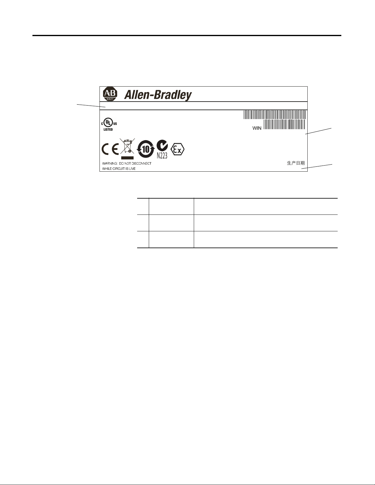
Product Information Location
Your product catalog number, serial number, and date code are located on the
product nameplate.
Record the following information in this table for future reference.
1 Catalog number
2 WIN/serial number
3 Date code
10 Rockwell Automation Publication 6181X-UM001B-EN-P - May 2011
Page 11
System Features Chapter 1
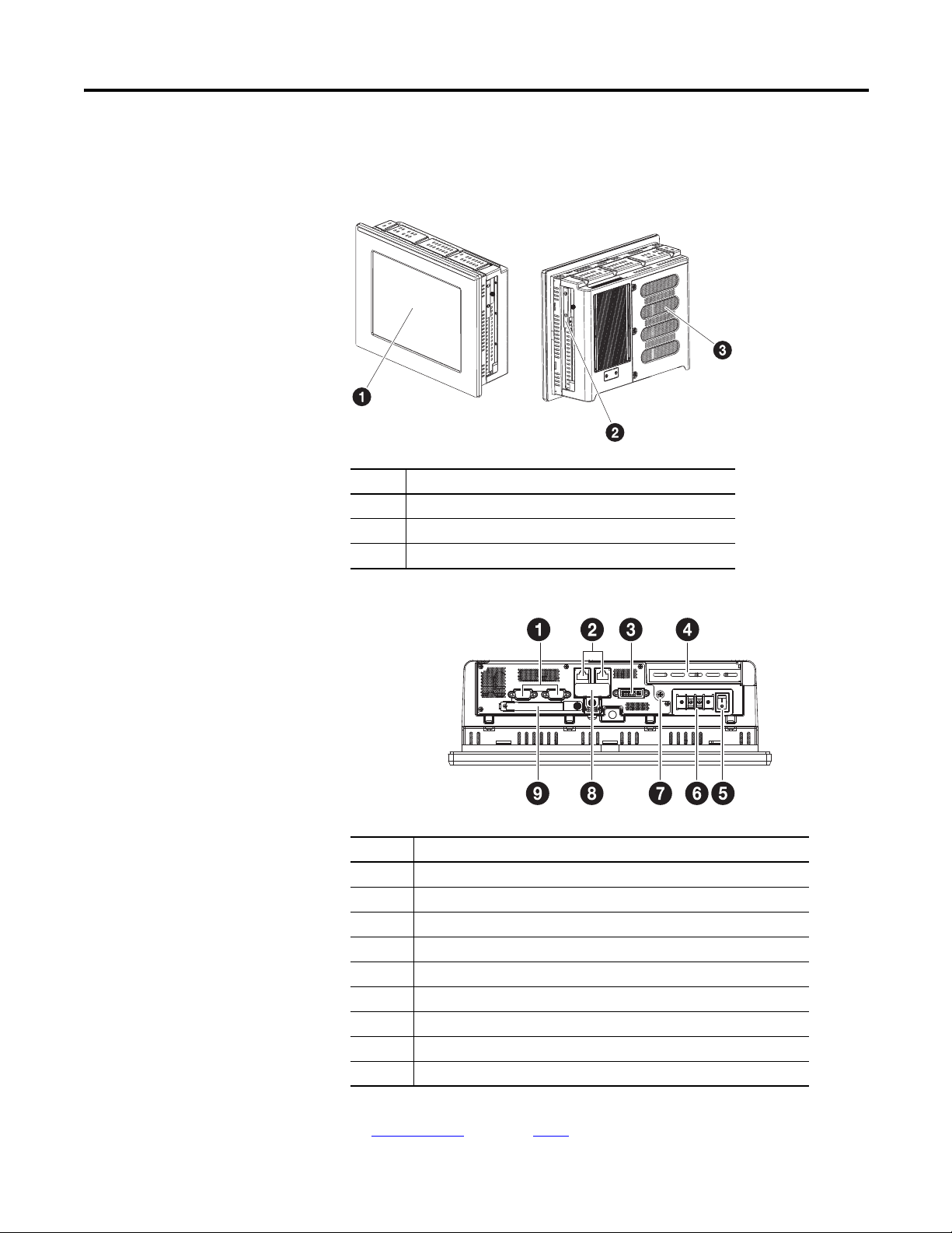
Hardware Features
The illustrations show the hardware features of the display industrial computers
for hazardous locations.
Figure 1 - Front and Side Views, Catalog Number 6181X-12TPXPDC
Item Component
1 LCD panel, display model only
2 Internal CompactFlash Type II solid-state drive bay
3Rear cover
Figure 2 - Bottom View, Catalog Number 6181X-12TPXPDC
Item Component
1 Serial COM ports, 2
2 Ethernet ports (RJ45), 2
3DVI-I port
4 PCI riser slot cover
5 Power switch
6 DC input terminal block
7 Functional ground screw
8 Hinged door covering 4 USB ports
9 External CompactFlash Type II card storage drive slot
(1) This bottom side external CF slot and USB ports are functionally hot-pluggable in an environment
known to be non-hazardous. For more information about proper use of these ports refer to
Hazardous Locations
Rockwell Automation Publication 6181X-UM001B-EN-P - May 2011 11
statements on page 14.
(1)
(1)
Page 12

Chapter 1 System Features
Notes:
12 Rockwell Automation Publication 6181X-UM001B-EN-P - May 2011
Page 13
Installation
Chapter
2
Chapter Objectives
European Union Directive Compliance
This chapter provides pre-installation information and procedures to mount the
computer and make connections:
• European Union compliance
• Environment and enclosure information
• Installation considerations
• Mounting clearances
• Product dimensions
• Mounting the display computer
• Mounting the non-display computer
• Connecting peripherals
• Applying power
• Functional ground screw
• Connecting to a network
This product meets the European Union Directive requirements when installed
within the European Union or EEA regions and have the CE mark. A copy of the
Declaration of Conformity is available at the Rockwell Automation website
http://www.ab.com
under Product Certification.
ATTENTION: To comply with EN 55022 and EN 55024, all I/O cables must
be less than 30 m (98.42 ft). These cables must not exit the building at any
point and shall not directly connect to cables outside the building.
To comply with EN 55022 and EN 55024, use the following shielded or
unshielded cable as specified in this table.
Table 1 - Shielded or Unshielded Cable
Cable Type Required Attribute
LAN Shielded or Unshielded
USB Shielded
Serial RS-232 Shielded
DVI Shielded
VGA Shielded
DC Power Unshielded
Rockwell Automation Publication 6181X-UM001B-EN-P - May 2011 13
Page 14
Chapter 2 Installation
Hazardous Locations
This equipment is suitable for these location categories.
Cat. No. Region Class/Division/Zone Rating Temperature
6181X-NPXPDC,
Non-display
6181X-12TPXPDC,
Display
(1) The entire 6181X-NPXPDC computer and the backside of the 6181X-12TPXPDC display are required to be mounted in a
restricted access location.
United
States
Canada Class I Division 2, Groups A, B, C, D T4
Europe
United
States
Canada Class I Division 2, Groups A, B, C, D T4
Europe
Class I Division 2, Groups A, B, C, D T4
Class I Zone 2, IIC, T4
Class I Zone 2, IIC, T4
ATEX II 3 GD, Ex nA IIC Gc, Ex tc IIIC Dc
Class I Division 2, Groups A, B, C, D T4
Class I Zone 2, IIC, T4
Class I Zone 2, IIC, T4
ATEX II 3 GD, Ex nA nC IIC T4 Gc,
Ex tc IIIC T135° Dc
(1)
-20 °C £ T
(-4 °F < Ta < 158 °F)
-20 °C £ T
(-4 °F < Ta < 131 °F) (Display side)
-20 °C £ T
(-4 °F < Ta < 158 °F) (Backside)
£ 70 °C
a
£ 55 °C
a
£ 70 °C
a
The following statement applies when the equipment is used in a hazardous
location.
WARNING: Explosion Hazard
•
Substitution of components may impair suitability for hazardous locations.
• Do not disconnect equipment unless power has been switched off and
area is known to be nonhazardous.
• Do not connect or disconnect components unless power has been
switched off.
• Peripheral equipment must be suitable for the location it is used in.
• In the U.S. all wiring must be in accordance with Class I, Division 2 wiring
methods of Article 501 of the National Electrical Code, and in accordance
with the authority having jurisdiction. Refer to control drawing
information in this document for allowable circuit parameters in Class I,
Division 2 applications.
• In Canada all wiring must be in accordance with Section 18-1J2 of the
Canadian Electrical Code, and in accordance with the authority having
jurisdiction.
• For European Zone 2 applications transient limiting shall be provided in
the application that limits transient overvoltages to not more than 40%
above the applied voltage.
• For European Zone 2 applications, non-display computers must be
mounted completely within an enclosure rated IP54 minimum.
•
For European Zone 2 (gases) applications computers with displays must be
mounted through the wall or door of an enclosure rated IP54 minimum. For
European Zone 22 (dusts) applications computers with displays must be
mounted through the wall or door of an enclosure rated IP6x minimum.
Computers with displays support enclosures rated up to IP66.
• For European Zone 2 applications do not use the USB ports unless the
area is known to be nonhazardous.
•
These devices shall be properly connected to ground in the final application
by using the ground terminal screw provided on the computer chassis.
(1)
14 Rockwell Automation Publication 6181X-UM001B-EN-P - May 2011
Page 15

Installation Chapter 2
Hot Surfaces
When used above 50 °C (122 °F) the backside of the 6181X-12TPXPDC
computer and the entire 6181X-NPXPDC computer must be installed in a
restricted access location.
Restricted Access Location
Restricted access locations for the equipment should meet these conditions:
• Access can be gained only by service personnel or by users who have been
instructed on the reasons for the restrictions applied to a location and
about any precautions that should be taken.
• Access is through the use of a tool or a lock and key, or other means of
security, and is controlled by the authority responsible for the location.
Rockwell Automation Publication 6181X-UM001B-EN-P - May 2011 15
Page 16
Chapter 2 Installation
USB Port USB Peripheral Device
USB Port USB Peripheral Device
USB Port USB Peripheral Device
USB Port USB Peripheral Device
6181X Host Product
Associated Nonincendive
Field Wiring Apparatus
Nonincendive Field
Wiring Apparatus
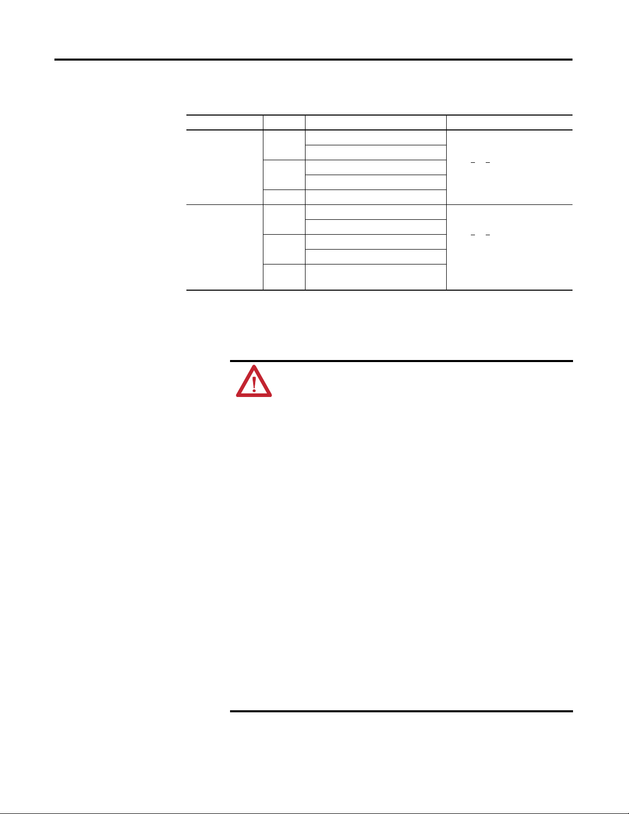
Control Drawing - Class I Division 2 and Zone 2 Required Circuit Parameters for USB Peripheral Devices
The following control drawing is provided in accordance with the National
Electrical Code, Article 500 (Class I, Zone 2, Group IIB and Class I, Division 2,
Groups A, B, C, and D).
Parameter Value Parameter Definition
V
oc (USB)
I
sc (USB)
C
a (USB)
L
a (USB)
5.25V DC Open circuit voltage of each host USB port.
The maximum applied voltage rating, V
peripheral device shall be greater than or equal to Voc
V
max (peripheral)
³ V
OC (USB), as appropriate
max (peripheral)
, of each
.
(USB)
950 mA Maximum output current of each host USB port.
The maximum current, I
device can be subjected shall be greater than or equal to Isc (USB) .
I
max (peripheral)
³ Isc
max (peripheral)
(USB)
, to which each USB peripheral
20 µF This value is the maximum total capacitance that can be connected
to each USB port. The total capacitance of each USB peripheral and
its cable must not exceed the indicated value.
The maximum total capacitance, C
of each separate USB peripheral device shall be less than or equal
to C
C
a (USB)
i ( peripheral)
.
+ C
£ C
cable
i (peripheral),
a (USB)
and cable capacitance
3.11 µH This value is the maximum total inductance that can be connected
to each USB port. The total inductance of each peripheral device
and its cable must not exceed the the indicated value.
The maximum total inductance, L
of each separate USB peripheral device shall be less than or equal
to L
a (USB).
L
i (peripheral)
+ L
cable
£ L
a (USB)
i (peripheral),
and cable inductance
Application Information
The circuit parameters of associated field-wired apparatus for use in hazardous
locations shall be coordinated with the host product such that their combination
remains nonincendive. The 6181X computers and the USB peripheral devices
shall be treated in this manner.
The circuit parameters of the 6181X computers’ USB ports are indicated in the
previous table. The 6181X computers provides four separately powered USB ports.
16 Rockwell Automation Publication 6181X-UM001B-EN-P - May 2011
Page 17

Installation Chapter 2
The USB peripheral devices and their associated cabling shall have circuit
parameters with the limits given in the Control Drawing - Class I Division 2 and
Zone 2 Required Circuit Parameters for USB Peripheral Devices section table for
them to remain nonincendive when used with the 6181X computers’ USB ports.
For the comparison of C
peripheral device, C
i(peripheral)
, use the capacitance of each individual connected USB
a(USB)
, and its associated cable, C
cable
.
If cable capacitance and inductance are not known, the following values may be
used:
= 197 µF/m (60 pF/ft)
C
cable
= 0.7 µH/m (0.20 µH/ft)
L
cable
Environment and Enclosure Information
Review the information on enclosures and environments before installing the
product.
ATTENTION: This equipment is intended for use in a Pollution Degree 2
industrial environment, in overvoltage Category II applications (as defined
in IEC publication 60664-1), at altitudes up to 2000 m (6561 ft) without
derating.
This equipment is considered Group 1, Class A industrial equipment
according to IEC/CISPR Publication 11. Without appropriate precautions,
there may be potential difficulties ensuring electromagnetic compatibility in
other environments due to conducted as well as radiated disturbance.
This equipment is supplied as an open-type equipment. It must be mounted
within an enclosure that is suitably designed for those specific
environmental conditions that will be present and appropriately designed to
prevent personal injury resulting from accessibility to live parts. The interior
of the enclosure must be accessible only by the use of a tool. Subsequent
sections of this publication may contain additional information regarding
specific enclosure type ratings that are required to be complied with certain
product safety certifications.
All 6181X-12 display units are shipped with a gasketed bezel to meet
specified NEMA, UL Type, and IEC ratings only when mounted in a panel or
enclosure with an equivalent rating. Other sections of this publication
contain additional information regarding specific enclosure-type ratings
required to comply with certain product safety certifications.
See NEMA Standard publication 250, UL 50, and IEC publication 60529, as
applicable, for explanations of the degrees of protection provided by
different types of enclosure. Also, see the appropriate sections in this
publication, as well as the Allen-Bradley publication 1770-4.1
Automation Wiring and Grounding Guidelines, for additional installation
requirements pertaining to this equipment.
, Industrial
Rockwell Automation Publication 6181X-UM001B-EN-P - May 2011 17
Page 18

Chapter 2 Installation
Environnements Dangereux
Cet équipement peut être utilisé dans les environnements suivants :
• Classe I, Division 2, Groupes A, B, C et D
• non dangereux
La mise en garde suivante s’applique à une utilisation en environnement
dangereux.
ATTENTION: Danger d'explosion
• La substitution de composants peut rendre cet équipement impropre à
une utilisation en environnement dangereux.
• Ne pas déconnecter l’équipement sans s’être assuré que l’alimentation
est coupée et que l’environnement est classé non dangereux.
• Ne pas connecter ou déconnecter des composants sans s’être assuré que
l’alimentation est coupée.
• L’ensemble du câblage doit être conforme à la réglementation en vigueur
dans le pays où cet équipement est installé.
• L’équipement périphérique doit être adapté à l’environnement dans
lequel il est utilisé.
• Tout équipement utilisé en environnement dangereux doit être monté
dans une armoire fournissant une protection adaptée aux conditions
d'utilisation ambiantes et suffisante pour éviter toute blessure corporelle
pouvant résulter d'un contact direct avec des composants sous tension.
Les ordinateurs ont un code de température T4 (135°C) lorsqu’ils fonctionnent
dans les températures ambiantes maximales suivantes. Voir également le
graphique Directives d’installationen page 19
de ce document.
• 6181X-12……55°C en face avant de l’écran et 70°C en face arrière, en cas
de montage comme prévu au travers de la paroi d’un coffret.
• 6181X-N……70°C au maximum, en cas de montage comme prévu à
l’intérieur d’un coffret.
N’installez pas l’ordinateur dans des environnements atmosphériques explosifs
(par ex. du gaz) dont la température d’inflammabilité est inférieure à 135°C.
18 Rockwell Automation Publication 6181X-UM001B-EN-P - May 2011
Page 19
Installation Chapter 2
TIP
IMPORTANT
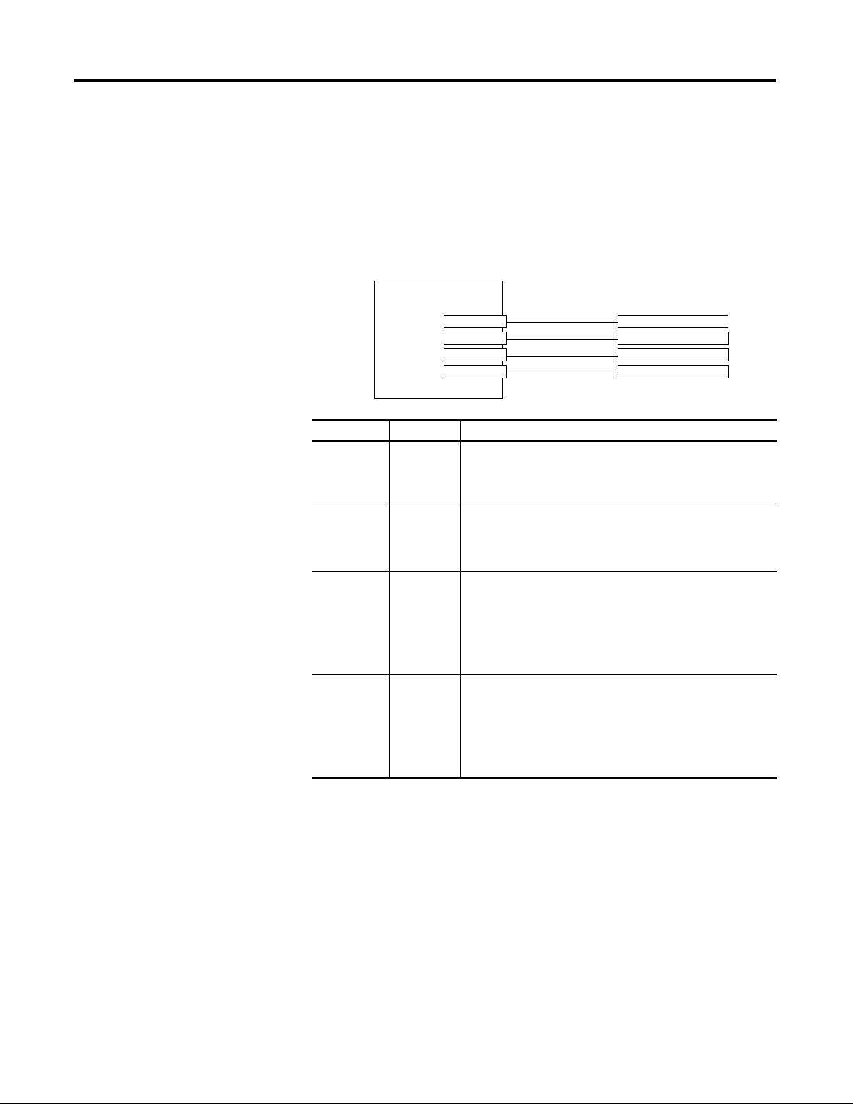
55 °C (131 °F)
70 °C (158 °F)
70 °C (158 °F)
Restricted Access Location
Non-display Computer
Display Computer
6181X-12TPXPDC Display Computer 6181X-NPXPDC Non-display Computer
Up
Up
Installation Guidelines
Follow these guidelines to make sure your product provides safe and reliable
service:
• The installation site must have sufficient power.
• The enclosure must allow sufficient space around air inlets and outlets to
provide the circulation necessary for cooling. Never allow air passages to
become obstructed.
• The ambient air temperature must not exceed the maximum operating
temperature. Consider heat produced by other devices in the enclosure.
You may need a user-supplied fan, heat exchanger, or air conditioner to
meet this condition.
Hot air rises. The temperature at the top of the enclosure is often
higher than the temperature in other parts of the enclosure, especially
if air is not circulating.
The product can operate at a range of extremes. However, the life span
of any electronic device is shortened if you continuously operate the
product at its highest rated temperature.
• The humidity of the ambient air must not exceed specified limits. In very
dry environments, static charges build up readily. Proper grounding of the
equipment helps to reduce static discharges, which may cause shocks and
damage electronic components.
• The enclosure or cover must remain in place at all times during operation.
The cover provides protection against high voltages inside the product and
inhibits radio-frequency emissions that might interfere with other
equipment.
• The product cannot be tilted from vertical. Mount as shown below.
Rockwell Automation Publication 6181X-UM001B-EN-P - May 2011 19
Page 20
Chapter 2 Installation
IMPORTANT
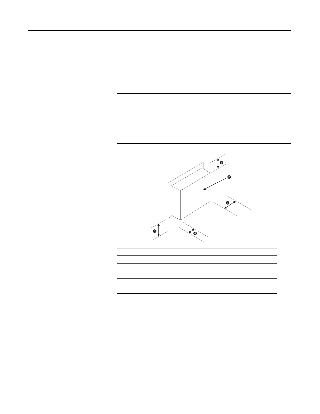
Mounting Clearances
When selecting an installation site for the computers, be sure to allow adequate
clearance on the sides and rear of the computer for proper ventilation, cable
connection, and hardware access. Sufficient airflow throughout the system unit is
required to maintain proper cooling. Clearance should be enough to allow
convenient installation or removal of peripheral components, such as the
CompactFlash card.
Use adequate ventilation or other cooling methods to maintain the
product temperature at its specified rating.
Because of self-heating, do not operate the computer in an enclosure by
using the minimum clearances unless adequate ventilation or other
cooling methods are used to lower the temperature within the enclosure.
The minimum required enclosure size (HxWxD) is 403 x 497 x 154 mm
(15.87 x 19.57 x 6.06 in.).
Item Description Value
1 Top 50 mm (2 in.)
2 Back 50 mm (2 in.)
3 Left (for airflow) 50 mm (2 in.)
4 Right (for airflow and drive access) 127 mm (5 in.)
5 Bottom (for I/O port access and ventilation) 102 mm (4 in.)
20 Rockwell Automation Publication 6181X-UM001B-EN-P - May 2011
Page 21
Installation Chapter 2
353.00 (13.90)
1.60 (0.06)
335.28 (13.20)
190.50 (7.5)
251.00 (9.88)
11.30 (0.44)
83.40 (3.28)
238.18 (9.37)
57.50 (2.26)
320.00 (12.60)
115.00 (4.53) 115.00 (4.53)
349.00 (13.74)
14.50 (0.57)
75.40 (2.97)
101.30 (3.99)
279.00 (10.98)
251.00 (9.88)
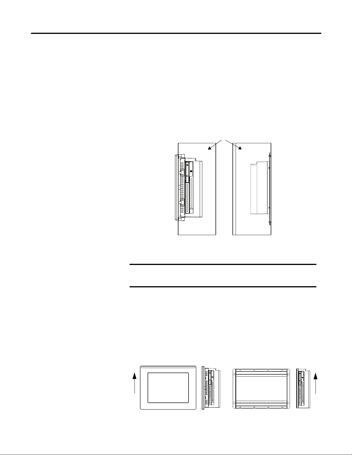
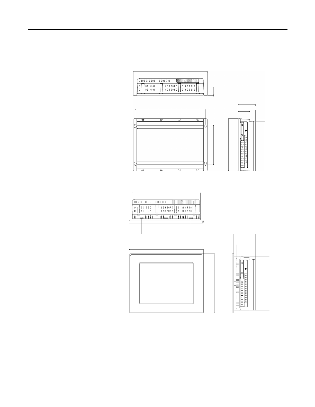
Product Dimensions
Product dimensions for the computers are given in mm (in.).
Figure 3 - Non-display Computer, Catalog Number 6181X-NPXPDC
Figure 4 - Integrated Display Computer, Catalog Number 6181X-12TPXPDC
Rockwell Automation Publication 6181X-UM001B-EN-P - May 2011 21
Page 22

Chapter 2 Installation
IMPORTANT
335.28 (13.2)
190.50 (7.50)
Install the Computer
The computers support these mounting options.
Cat. No. Computer Model Mounting Option
6181X-NPXPDC Non-display Wall mount
6181X-12TPXPDC
(1) Display computers must be securely mounted by using all mounting clips.
(1)
Display Panel mount
Mount the Non-display Computer on a Wall
Four mounting screws secure the non-display computer to a metal wall, such as a
steel mounting panel in an enclosure or equipment room.
Do not mount the non-display computer on a horizontal surface.
Follow these steps to mount a non-display computer.
1. Disconnect power from the computer.
2. Attach two of the supplied M4 panhead screws with grommets
to the 1 and 2 screw position as illustrated below.
3. Mount the computer on the wall and then attach the remaining two M4
panhead screws with grommets to the 3 and 4 screw position.
4. Tighten the screws to a torque that is appropriate for the screw and wall.
Recommended torque in steel is 1.13…1.36 N•m (10…12 lb•in).
The illustration shows the location of the screw holes with the dimensions
given in mm (in.).
22 Rockwell Automation Publication 6181X-UM001B-EN-P - May 2011
Page 23

Installation Chapter 2
IMPORTANT
Mount the Display Computer in a Panel
Mounting clips secure the 6181X-12TPXPDC display computer to the panel.
Make sure to mount the computer vertically.
Panel Mounting Guidelines
Observe these guidelines when installing the unit in a panel:
• Remove all electrical power from the panel before making the cutout.
• Confirm that there is adequate space behind the panel. For specific
information refer to Mounting Clearances
• Cut supporting panel cutout to specifications before installation. Take
precautions so metal cuttings do not enter components already installed in
panel.
Supporting panels must be at least 14 gauge to be sure of proper sealing
against water and dust and to provide proper support. The mounting
hardware supplied accommodates panel thickness between 14…8 ga or
1.6…4.2 mm (0.063…0.165 in.).
• Make sure the area around the panel cutout is clear.
on page 20.
Failure to follow these guidelines may result in personal injury or damage
to the panel components.
Panel Cutout Dimensions
The 6181X-12TPXPDC display computer must be appropriately mounted in
the panel cutout specified below.
Computer Cutout Dimensions (HxW), approx.
6181X-12TPXPDC 254.0 x 324.0 mm (10.0 x 12.76 in.)
Follow these steps to mount the computer in a panel.
1. Remove power from the panel.
2. Cut an opening in the panel by using the appropriate panel cutout
dimensions.
3. Place the computer in the panel cutout.
Rockwell Automation Publication 6181X-UM001B-EN-P - May 2011 23
Page 24

Chapter 2 Installation
1
109
2
7
8
5
4
3
6
4. Slide the mounting clips into the holes on the top, bottom, and sides of the
computer.
5. Gradually tighten the clips, one at a time, around the bezel by using the
specified sequence starting with the center clips and continuing to the
corner clips.
6. Tighten the mounting clips to a torque of 1.4 N•m (12 lb•in) by using the
sequence in step 5, being sure not to overtighten.
Repeat this process at least three times until the clips are properly torqued,
making sure the gasket is compressed uniformly against the panel.
ATTENTION: Tighten the mounting clips to the specified torque to
provide a proper seal and prevent damage to the product. Rockwell
Automation assumes no responsibility for water or chemical damage to
the product or other equipment within the enclosure because of improper
installation.
24 Rockwell Automation Publication 6181X-UM001B-EN-P - May 2011
Page 25

Installation Chapter 2
IMPORTANT
Connect Peripherals
Apply Power
Connect the required peripherals, such as keyboard and mouse, to the
corresponding I/O ports on the bottom side of the computer. Refer to the
illustration on the previous section for connector locations.
Observe these guidelines when connecting peripherals to the computer:
• When connecting a device to the serial COM or DVI port, secure the
connected device with screws.
• The USB ports are covered by a hinged door.
For more information about proper use of these ports refer to Hazardous
Locations statements on page 14.
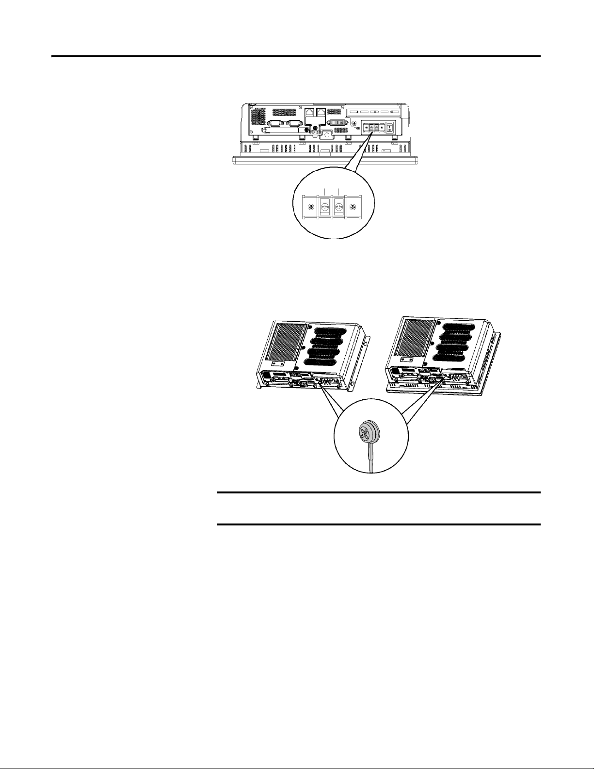
Both the display and non-display computers have a DC input terminal block for
connecting to an 18…32V DC power source.
ATTENTION: The computer circuit should have its own disconnect. Use
an uninterruptible power source (UPS) to protect against unexpected
power failure or power surges.
Always shut down the operating system before removing power to minimize
performance degradation and operating system failures.
The DC power option supports operation from safety extra-low voltage (SELV)
power source.
The power supply is internally protected against reverse polarity.
ATTENTION: Use an SELV isolated and ungrounded power supply as
input power to the computer. This power source provides protection so
that under normal and single fault conditions, the voltage between the
conductors and Functional Earth/Protective Earth does not exceed a safe
value.
A functional ground connection is required for EMC compliance.
Follow these steps to connect the computer to a DC power source.
1. Verify the main power switch or breaker is off.
2. Verify that the DC power wires meet these requirements:
– Material: Stranded copper
– Wire gauge: 0.823…2.08 mm
2
(18…14 AWG)
Rockwell Automation Publication 6181X-UM001B-EN-P - May 2011 25
Page 26
Chapter 2 Installation
IMPORTANT
6181X-12TPXPDC
Display Computer Shown
-V +V
-V +V
6181X-NPXPDC
Non-display Computer
6181X-12TPXPDC
Display Computer
3. Secure the DC power wires to the terminal block screws.
Tighten the terminal to a torque of 0.687 N•m (6.1 lb•in).
4. Secure the ground wire by using a ring style connector to the functional
earth terminal screw.
Tighten to a torque of 1.47 N•m (13 lb•in).
When using the functional ground screw, connect the product to earth
2
ground by using a 1.5 mm
(16 AWG) or larger external wire.
5. Apply 18…32V DC power to the computer.
26 Rockwell Automation Publication 6181X-UM001B-EN-P - May 2011
Page 27

Installation Chapter 2
IMPORTANT
6181X-12TPXPDC
Display Computer
6181X-NPXPDC
Non-display Computer
Connect to a Network
The computers have two 1 GB LAN ports. The computers connect to an
Ethernet network by using CAT5 or CAT5E twisted-pair Ethernet cabling with
RJ45 connectors.
ATTENTION: When connecting a LAN cable, make sure the cable is fully
inserted in the LAN port and that the latch is engaged. Failure to do so
could result in an electrical arc that can cause an explosion in a hazardous
location.
To prevent performance degradation of Ethernet communication, do not
subject the computer or cables to extreme radiation or conducted highfrequency noise.
Proper cable routing and power conditioning is required to be sure of
reliable Ethernet communication in an industrial environment. Rockwell
Automation recommends that you route all Ethernet cabling through
dedicated metal conduits. Installing ferrite bead filters at the cable ends
may also improve reliability.
Rockwell Automation Publication 6181X-UM001B-EN-P - May 2011 27
Page 28

Chapter 2 Installation
Notes:
28 Rockwell Automation Publication 6181X-UM001B-EN-P - May 2011
Page 29

Operation
Chapter
3
Chapter Objectives
Operating Guidelines
This chapter covers these topics:
• Operating guidelines
• Operator access
• Starting the system
• Resetting the system
Follow these operating guidelines for your computer:
• To avoid dust and other airborne contamination infiltrating the product
when mounted in a suitable enclosure, the door to the enclosure must be
closed at all times during operation. The door should be open for routine
maintenance only.
• Avoid turning the system on and off frequently.
• Always use the proper power down procedures as required by your
operating system, such as the Shut Down command in the Microsoft
Windows operating system. A properly configured UPS can assist in this
procedure.
• After the shutdown is complete, wait 15 seconds before turning the
computer back on.
Operator Access
SHOCK HAZARD: Do not operate the computer with the covers
removed. An electrical shock hazard exists. All covers are required to
maintain electromagnetic interference (EMI) shield.
ATTENTION: Operator access is limited to the front panel of the
computer. This includes the display and the touch screen (if available).
Access to components behind the panel in which the computer is installed
is restricted to authorized and properly trained personnel.
Rockwell Automation Publication 6181X-UM001B-EN-P - May 2011 29
Page 30

Chapter 3 Operation
Starting the System
Resetting the System
Before starting the computer, make sure peripheral devices are connected to their
corresponding I/O ports.
For more information about I/O ports see Hardware Features
When power is applied to the computer, it will start without having to press the
power switch. This is the default mode of operation when power is applied. You
can change the default mode of operation in the After Power Fail setting of the
BIOS Power menu.
The computer performs a Power On Self Test (POST). The processor board,
memory, keyboard, and certain peripheral devices are tested.
If your system does not start, or you notice other anomalies, refer to the System
Troubleshooting chapter on page 41.
To reset the computer, press CTRL+ALT+Delete on an attached keyboard and
follow the operating system instructions.
After resetting, the computer begins the POST. During a reset, the computer
does the following:
• Clears RAM
• Starts the POST
• Initializes peripheral devices, such as drives and printers
• Loads the operating system
on page 11.
30 Rockwell Automation Publication 6181X-UM001B-EN-P - May 2011
Page 31

Component Replacement
IMPORTANT
Chapter
4
Chapter Objectives
This chapter provides procedures to do the following:
• Remove and reinstall the rear cover
• Replace the CompactFlash hard disk drive
• Install a CompactFlash data card
• Install an add-in card
• Upgrade the system memory
Before performing any component replacement procedures, review
Hazardous Locations
ATTENTION: Make sure to read and understand the entire installation or
removal procedure first, before you begin configuring the computer
hardware.
Review the specifications of a new component before installing it to make
sure it is compatible with the computer. Record the model and serial
number, and any other pertinent information of new components for
future reference
information on page 14.
When installing hardware or performing maintenance procedures
requiring access to internal components, we recommend that you first
back up all computer data to avoid loss.
Accessories and Replacement Parts
You can view a current list of accessories at the Rockwell Automation website
http://
www.ab.com/industrialcomputers..
ATTENTION: To prevent voiding your product warranty, use only
Rockwell Automation Allen-Bradley approved replacement parts and
accessories.
Rockwell Automation Publication 6181X-UM001B-EN-P - May 2011 31
Page 32

Chapter 4 Component Replacement
Voltage Precaution
Electrostatic Discharge (ESD)
Required Tools
The computers contain line voltages. Disconnect all power to the computer
before you install or remove system components.
SHOCK HAZARD: Disconnect power from the computer before removing
components. Failure to disconnect power could result in severe electrical
shock or damage to the computer.
ATTENTION: Electrostatic discharge (ESD) can damage the computer and
components. Make sure you work in a static-safe environment and wear a
grounding strap whenever handling circuit boards, power supplies,
memory modules, or other internal components.
These tools are required for component replacement:
• #2 Phillips screwdriver
ATTENTION: Use a #2 Phillips screwdriver for all screws. Using the
wrong size tool may damage the screw head.
Rear Cover
• Scissors (for DIMM replacement only)
• Antistatic wrist strap (recommended)
To install or upgrade internal computer components, you must first remove the
rear cover.
SHOCK HAZARD: Disconnect power from the computer before removing
components. Failure to disconnect power could result in severe electrical
shock or damage to the computer.
32 Rockwell Automation Publication 6181X-UM001B-EN-P - May 2011
Page 33

Component Replacement Chapter 4
6181X-12TPXPDC Display Computer
6181X-12TPXPDC Display Computer
Follow these steps to remove the rear cover.
1. Disconnect power from the computer.
2. Loosen the three screws that secure the rear cover (1).
3. Open the cover and detach it from the chassis (2).
Follow these steps to reinstall the rear cover.
1. Fasten the rear cover to the chassis (1).
2. Tighten the three screws to secure the rear cover (2).
Rockwell Automation Publication 6181X-UM001B-EN-P - May 2011 33
Page 34

Chapter 4 Component Replacement
IMPORTANT
6181X-12TPXPDC
Display Computer
CompactFlash Card
The computers have two CompactFlash (CF) Type II card slots for installing CF
cards:
• Internal CF slot (right side) – Cards installed in this slot are considered
bootable and are designed to function as a main hard disk drive. Do not
remove or install a card in this slot while the computer is powered on.
• External CF slot (bottom side) – This slot is functionally hot-pluggable in
an environment known to be nonhazardous. This slot is meant to be a data
CF slot but is bootable.
Use only catalog numbers 6189V-CFSSD8GB and 6189V-CFSSD16GB
CompactFlash (CF) cards in the 6181X industrial computers for hazardous
locations. Other replacement cards are not acceptable for use in
hazardous locations.
Install a CF Card in the External CF Card Slo
t
Follow these steps to install a CF card in the external CF card slot.
1. Loosen the screw that secures the CF card slot cover (1).
2. Open the CF card slot cover (2).
3. If necessary, remove existing card by pushing the button on the hinge side.
4. Insert the CF card into the slot until it is firmly seated (3).
5. Close the CF card slot cover, then tighten its screw (1).
34 Rockwell Automation Publication 6181X-UM001B-EN-P - May 2011
Page 35

Component Replacement Chapter 4
IMPORTANT
6181X-12TPXPDC Display Computer
Install a CF Card in the Internal CF Card Slot
Follow these steps to install a CF card in the internal CF card slot.
1. Disconnect power from the computer.
2. Loosen the screw that secures the CF card slot cover (1), then the screw
that secures the CF card slot lever (2).
3. Extend the CF card slot lever (3), then pull out the CF card tray (4).
4. Remove the CF card lock screw (5).
If necessary, remove existing CF card by sliding it out of the slot.
5. Insert the CF card into the slot until it is firmly seated (6).
6. Secure the CF card with the CF card lock screw, then reinstall the CF card
tray into the computer.
7. Tighten the CF card slot cover and lever screws.
Reinstalling the CF card lock screw is required to meet hazardous
locations, mechanical shock, and vibration requirements.
Rockwell Automation Publication 6181X-UM001B-EN-P - May 2011 35
Page 36

Chapter 4 Component Replacement
IMPORTANT
PCI Add-in Cards
When used in hazardous locations the computer supports peripheral
cards rated 4 W maximum, and Class I, Division 2, Groups A, B, C, D, T4.
In Europe, use in ATEX Group IIC Category 3 gas and dust environments is
supported. At maximum product temperature a PCI card dissipating 4 W
may experience a surrounding air temperature up to 90
card dissipating 1 W may experience a surrounding air temperature up to
°C (185 °F) .
85
Follows these steps to install an add-in card.
1. Disconnect power from the computer.
2. Remove the back cover from the computer.
Refer to Rear Cover
instructions on page 32 for more information.
3. Remove the one screw that secures the slot cover.
Do not discard the screw.
4. Remove the slot cover and store it for reassembly later.
ATTENTION: Do not discard the slot cover. If the add-in card is removed
in the future, the slot cover must be reinstalled to maintain agency access
requirements.
°C (194 °F). A PCI
5. Hold the add-in card by its edge and remove it from its protective
packaging.
6. Connect the add-in card to the compatible riser-board slot, making sure
that the card is properly seated in the slot.
7. Secure the add-in card with the screw from the slot cover.
8. Connect the necessary cables to the add-in card.
Refer to the documentation that came with the card.
9. Reinstall the rear cover.
Refer to Rear Cover
instructions on page 32 for more information.
36 Rockwell Automation Publication 6181X-UM001B-EN-P - May 2011
Page 37
Component Replacement Chapter 4
TIP
IMPORTANT
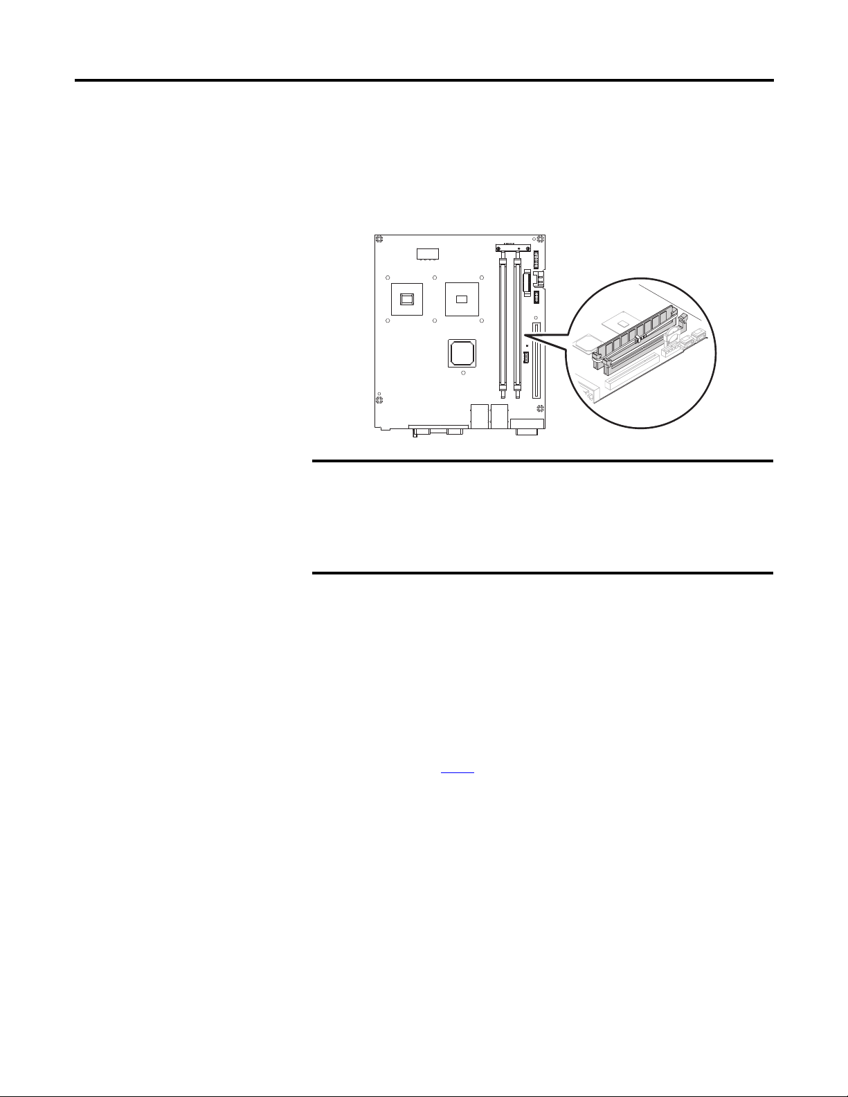
Memory Module
The computers have two dual-channel DDR2 DIMM slots that support up to
4 GB maximum system memory.
Microsoft Windows operating system limits the maximum usable
capacity to approximately 3 GB.
Use only catalog number 6189X-4GDDR2 in the 6181X industrial
computers for hazardous locations. Other memory modules are not
acceptable for use in hazardous locations.
When installing two memory modules, make sure to use the same brand
and model number. Installing two modules of different type could cause
the system to become unstable.
Upgrade the System Memory
Follow these steps to upgrade the system memory.
1. Disconnect power from the computer.
2. Remove the rear cover.
3. If you want to install an additional module instead of replacing the default
one, proceed to step 8
.
Rockwell Automation Publication 6181X-UM001B-EN-P - May 2011 37
Page 38

Chapter 4 Component Replacement
TIP
B
B
A
6181X-12TPXPDC Display Computer
C
C
D
6181X-12TPXPDC Display Computer
4. Clip the cable tie of the existing memory module (A) and remove it from
the memory slot (B).
5. Completely open the retaining latches securing the memory module (C).
This forces the module up in the slot and makes it easier to remove.
6. Gently remove the memory module from its slot (D).
7. Place the memory module on a static-dissipating work surface or inside an
antistatic bag.
8. Hold the new memory module by its edge and remove it from its
protective packaging.
9. Orient the module so that the notch on its bottom edge aligns with the
keyed surface of the DIMM1 slot (E).
If you insert a memory module but it does not fit easily into the slot, you
may have inserted it incorrectly. Be sure of proper orientation and model
type and reinsert.
38 Rockwell Automation Publication 6181X-UM001B-EN-P - May 2011
Page 39

Component Replacement Chapter 4
IMPORTANT
E
E
F
G
H
H
10. Push the module at both ends to seat it fully into the slot (F).
The holding clips will automatically lock into place once the module has
been seated.
11. Fasten a replacement cable tie around the DIMM slot latches (G).
Reinstalling the cable tie is required to meet hazardous locations,
mechanical shock, and vibration requirements.
12. Pull the end of the cable tie to lock it in place (H).
13. Cut the excess length of the cable tie.
14. Repeat steps 4
…13 for DIMM2 slot if a second memory module is
installed.
15. Reinstall the rear cover.
16. Apply power to the computer.
Rockwell Automation Publication 6181X-UM001B-EN-P - May 2011 39
Page 40

Chapter 4 Component Replacement
Notes:
40 Rockwell Automation Publication 6181X-UM001B-EN-P - May 2011
Page 41

System Troubleshooting
Chapter
5
Chapter Objectives
Hardware Diagnostics
This chapter provides information on the these topics:
• Hardware diagnostics
• Troubleshooting procedure
• Diagnostic utility
• Clearing CMOS procedure
• Troubleshooting checklists
The built-in hardware monitor of the computer tracks the operating threshold
levels of the voltage and temperature sensors.
Follow these steps to determine whether an operating threshold has been reached.
1. Shut down the computer by using the appropriate method for the installed
operating system.
2. Apply power to the computer.
3. During POST, press F2 to enter BIOS Setup.
4. Select the Hardware Monitor menu from the BIOS-Advanced menu.
Rockwell Automation Publication 6181X-UM001B-EN-P - May 2011 41
Page 42

Chapter 5 System Troubleshooting
IMPORTANT
Troubleshooting Procedure
Before performing any maintenance procedures, review the safety
information in Hazardous Locations
hazardous locations.
Follow this procedure to identify and isolate a problem with the computer’s
operation.
1. Shut down the computer by using the appropriate method for the installed
operating system.
2. Disconnect power from the computer.
3. Disconnect all peripheral devices from the computer.
4. Connect the keyboard and mouse, if used.
5. Check the video connection if using an external monitor.
6. Connect power to the computer and check the POST.
One of three events will occur:
• The computer completes the start-up process.
• An error message displays to indicate a nonfatal fault. You may have to
acknowledge the message before the start-up process continues.
• The start-up process terminates if a fatal error occurs.
on page 14 for equipment used in
Diagnostic Utility
7. If the system starts, isolate the problem by connecting peripheral devices
one at a time until the problem occurs.
If the problem is with a specific software package, or driver, reinstall the
software.
If the problem is not related specifically to a software installation or a
peripheral device, refer to the diagnostic utility and the troubleshooting
checklists.
If you followed the troubleshooting procedure and are still having problems, use
the diagnostic utility to isolate the problem. This utility determines the cause of
the malfunction by testing computer components.
The diagnostic utility and documentation are on the Support CD that ships with
your computer. To run the diagnostic utility, attach an external CD-rom drive
and restart the computer. No software is installed, nor does the utility affect any
software already installed.
You can perform an initial diagnosis without disconnecting or moving your
computer. The process takes as little as five minutes or as long as eight hours,
depending on the tests selected. After the diagnostic utility has run, you can
generate a report for analysis by a technical support representative, expediting any
necessary repair process.
42 Rockwell Automation Publication 6181X-UM001B-EN-P - May 2011
Page 43

System Troubleshooting Chapter 5
CMOS
Header
Battery
Clear CMOS
If the system configuration has been corrupted, or if an incorrect set-up setting
has caused error messages to be unreadable, you need to clear the system
configuration values stored in the CMOS.
ATTENTION: Do not clear CMOS unless power has been disconnected
and area is known to be nonhazardous.
Use the clear CMOS header (CN5) to reset the CMOS data.
Follow these steps to clear the CMOS.
1. Back up all system data and then power down the computer.
2. Disconnect the power and peripheral cables from the computer.
3. Remove the rear cover.
4. Locate the clear CMOS header (CN5) on the system board.
5. Use a conductive tool, for example, a screwdriver, to make contact between
the two pins for ten seconds.
6. Reinstall the rear cover.
7. Attach a keyboard to your computer.
8. If you are using a non-display computer, attach an external monitor.
9. Reconnect the power cable to the computer.
10. During POST, press F2 to enter BIOS Setup.
11. On the Exit menu page, select Load Setup Defaults, and then press Enter.
12. Select Exit Saving Changes to reset the system configuration to factory
defaults and close BIOS Setup.
Rockwell Automation Publication 6181X-UM001B-EN-P - May 2011 43
Page 44

Chapter 5 System Troubleshooting
Troubleshooting Checklists
The troubleshooting table lists typical problems you may encounter when using
your computer. It contains symptoms and possible actions to correct a problem.
Problems During Startup
• Are all connections secure?
• Are the device drivers installed?
• Is the CompactFlash hard disk drive formatted and recognized correctly in
the BIOS Setup?
• Is the memory module properly installed?
• Is BIOS properly configured? Select Load Default in the CMOS setup
procedure. This will restore the BIOS settings to the original factory
settings.
Problems After Startup
• If the problem is intermittent, you may have a loose connection. Check all
connections including any add-in cards. Check that the memory module is
fully installed.
• Does your system have a computer virus? Run anti-virus software.
• Clear CMOS. Go to page 43
• If there is a flickering display or a locked system, exit the application and
restart the computer. Although the computers have a regulated and
protected power supply, a transient voltage in the power line or peripheral
cable could cause errors.
• If there are problems from the CompactFlash hard disk drive, you may
want to check if the system will start from a USB floppy disk or any other
bootable device.
• Verify that the ambient air temperature does not exceed its rated
specification. Refer to Appendix
vent holes are free of dust and debris.
• Check for proper clearance around the computer to verify adequate air
flow. Refer to Mounting Clearances
for details.
A, Specifications. Verify the heat sink and
on page 20.
Problems Running the New Software
• Does the software have a hardware requirement that is not present?
• Are you using an authorized copy of the software? Some copies of software
will not work without proper activation.
• Did the software install correctly? Reinstall the software.
• Are you following the software’s instructions? Refer to the software
vendor’s user manual.
44 Rockwell Automation Publication 6181X-UM001B-EN-P - May 2011
Page 45

System Troubleshooting Chapter 5
IMPORTANT
IMPORTANT
Problems with the Add-in Card
• Is the card installed and configured correctly? Check the configuration
settings.
• Are all necessary add-in cables properly connected?
• Check that the card is not overheating.
When used in hazardous locations the computer supports peripheral
cards rated 4 W maximum, and Class I, Division 2, Groups A, B,C, D, T4.
At maximum product temperature a PCI card dissipating 4 W may
experience a surrounding air temperature up to 90 °C (194 °F). A PCI card
dissipating 1 W may experience a surrounding air temperature up to
85 °C (185 °F).
Problems with the Integrated Display
• Check that the selected character color is not the same as the background
color.
• Try setting to the native resolution. Refer to Appendix
A - Specifications.
Adjust the Display Brightness
Problems with an External Display
• Are the display contrast and brightness controls properly adjusted? Refer
to the operating system containing the video driver for setup functions.
• Check that the selected character color is not the same as the background
color.
• Is the monitor compatible with the selected video mode?
• Is the video cable properly connected?
• Is the video driver properly installed?
• Restart the computer with the external monitor connected and powered
up.
• Is the monitor functioning properly? Verify the monitor function by
operating it with another computer.
The 6181X-12TPXPDC display computer has an adjustable display brightness
setting that can be adjusted in the BIOS setup.
After applying power to the computer, press F2 during POST to enter the BIOS
setup. The display brightness default setting is 70%.
Increasing the brightness from the default setting will reduce the life of
the LED backlight, particularly at high temperatures.
Rockwell Automation Publication 6181X-UM001B-EN-P - May 2011 45
Page 46

Chapter 5 System Troubleshooting
Notes:
46 Rockwell Automation Publication 6181X-UM001B-EN-P - May 2011
Page 47
Maintenance
Chapter
6
Chapter Objectives
Cleaning the Computer
This chapter provides information on how to do the following:
• Clean the computer
• Ship or transport the computer
It is important to maintain your computer by cleaning the display, heat sink and
vent holes, and removing grease or paint.
Clean the Integrated Display
ATTENTION: Use of abrasive cleansers or solvents may damage
the display window. Do not scrub or use brushes.
Follow these steps to clean the display.
1. Disconnect power from the computer at the power source.
2. Clean the display with a mild soap or detergent by using a clean sponge or a
soft cloth.
3. Dry the display with a chamois or moist cellulose sponge to avoid water
spots.
ATTENTION: If the computer has a touch screen, be aware that it
is possible for screen objects to activate during equipment washdowns if the computer is turned on.
Clean the Heat Sink and Vent Holes
Follow these steps to clean the chassis.
1. Disconnect power from the computer at the power source.
2. Disconnect all peripheral devices from the computer.
3. Vacuum dust and debris from the heat sink and vent holes.
Rockwell Automation Publication 6181X-UM001B-EN-P - May 2011 47
Page 48

Chapter 6 Maintenance
Remove Paint and Grease from Bezel
Follow these steps to remove paint and grease from the bezel of computers
properly mounted in NEMA Type 4/4X or IEC IP66 enclosures.
1. Remove paint splashes and grease by rubbing lightly with isopropyl
alcohol.
ATTENTION: Make sure the isopropyl alcohol does not come in
contact with the equipment labels. Alcohol may cause the label
printing to smear.
2. Use a mild soap or detergent solution to remove residue.
3. Rinse with clean water.
RTC Battery
This product contains a lithium battery, which is not user replaceable. Return the
computer to Rockwell Automation for battery replacement.
At the end of its life, the battery contained in this product should be
collected separately from any unsorted municipal waste.
The collection and recycling of batteries helps protect the environment
and contributes to the conservation of natural resources as valuable
materials are recovered.
48 Rockwell Automation Publication 6181X-UM001B-EN-P - May 2011
Page 49

Maintenance Chapter 6
Remove the Battery
Follow these steps to remove the RTC battery for proper disposal.
1. Disconnect power from the computer.
2. Remove the rear cover.
3. Remove the battery cover (1).
4. Remove the old battery from its socket (2).
Transporting the Product
If you need to ship your computer via common carrier or otherwise transport it to
another location, you must first uninstall the unit from the panel and place it in
its original packing material.
ATTENTION: Do not ship or transport the product when it is installed in a
machine, panel or rack. Doing so may cause damage to the product. You
must uninstall the product and place in its original packing material
before shipping. Rockwell Automation is not responsible for damage
incurred to a product that is shipped or transported while installed in a
machine, panel, or rack.
Rockwell Automation Publication 6181X-UM001B-EN-P - May 2011 49
Page 50

Chapter 6 Maintenance
Notes:
50 Rockwell Automation Publication 6181X-UM001B-EN-P - May 2011
Page 51

Appendix
Specifications
Table 2 - Technical Specifications - 6181X-NPXPDC, 6181X-12TPXPDC
Attribute Value
Processor Intel Core Duo U2500, 1.2 GHz/2 M L2 cache/533 MHz 9 W
System chipset Intel 945GME, ICH7-M
System memory slots Dual channel DDR II, 2 DIMM slots, 4 GB max
System memory, installed 2 GB shipped, 4 GB max
Expansion slot 1 half-length PCI
CompactFlash Type II slot
External
Internal
I/O ports DVI-I port, 2 serial COM ports, 4 USB ports
Ethernet LAN 2 LAN ports (RJ45), 1 Gigabit each
Operating systems Windows XP Professional for Embedded Systems
2 bootable slots
Hot-swappable storage drive slot
True IDE, 8 GB min CompactFlash drive installed
A
Table 3 - Display Specifications
Attribute Value
Display type Active Matrix Color TFT
Touch screen Resistive, sunlight readable film
Display size (diagonal) 308 mm (12.1 in.)
Display brightness 600 cd/m
Contrast ratio 1500:1, typical
Resolution, native 800 x 600, 16.2 M colors
Viewing angle 178° typical
Response time 15 ms (typical)
LED backlight life time 50,000 hours over the entire operating temperature range at the
default 70% brightness
2
, typical
Rockwell Automation Publication 6181X-UM001B-EN-P - May 2011 51
Page 52

Appendix A Specifications
Table 4 - Mechanical Specifications
Attribute Value
Weight, approx.
6181X-NPXPDC, non-display
6181X-12TPXPDC, display
6.1 kg (13.45 lb)
8.4 kg (18.52 lb)
Dimensions, (HxWxD), approx. overall
6181X-NPXPDC, non-display
6181X-12TPXPDC, display
Cutout dimensions (HxW)
6181X-12TPXPDC
Mounting options
Display models
Non-display models
251 x 353 x 83.4 mm (7.5 x 13.20 x 3.28 in.)
279 x 349 x 101.2 mm (10.98 x 13.74 x 3.98 in.)
254.0 x 324.0 mm (10.0 x 12.76 in.)
Panel mount
Wall mount
Table 5 - Electrical Specifications
Attribute Value
Input voltage, DC 18…32V DC
Power consumption, DC (max)
6181X-NPXPDC, non-display
6181X-12TPXPDC, display
Heat dissipation
(1)
6181X-NPXPDC, non-display
6181X-12TPXPDC, display
Peripheral loading
PCI card, max
(2)
USB ports, max per port
(1) Add-in cards and peripherals are included in the heat dissipation value.
(2) Refer to PCI Add-in Cards on page 36 for more information.
18…32V DC (SELV), 2.46…1.34 A, 45 W
18…32V DC (SELV), 3.28…1.79 A, 60 W
45 W (154 BTU/h)
60 W (205 BTU/h)
4 W
500 mA
Table 6 - Environmental Specifications
Attribute Value
Temperature, operating
6181X-NPXPDC, non-display
6181X-12TPXPDC, display
(1)
Temperature, nonoperating -30…80 °C (-22…176 °F)
Relative humidity 10…90% without condensation
Altitude, operating 2,000 m (6,561 ft)
Altitude, nonoperating 12,000 m (40,000 ft)
Shock, operating
(2)
Shock, nonoperating 30 g (1/2 sine, 11 ms)
Vibration, operating 0.012 in p-p (10…57 Hz); 2 g peak (57…640 Hz)
Enclosure ratings
(3)
6181X-12TPXPDC
(1) See Installation Guidelines on page 19 for more information about temperature guidelines.
(2) Applies to panel-mounted computers only.
(3) Ratings apply when computer is properly mounted on a flat surface of an equivalent type enclosure.
-20…70 °C (-4…158 °F)
-20…55 °C (-4…131 °F), display side
-20…70 °C (-4…158 °F), back side
15 g (1/2 sine, 11 ms)
Rated UL Type 4X and 12, also rated IP66 as Classified by UL
52 Rockwell Automation Publication 6181X-UM001B-EN-P - May 2011
Page 53

Specifications Appendix A
Certifications
Attribute
c-UL-us UL/c-UL Listed as Information Technology Equipment for Use
ATEX Certified per EN60079-15
CE Marked for all applicable directives
C-Tick Australian Radiocommunications Act, compliant with:
RoHS China, Turkey, European
(1) See http://www.ab.com for declarations of conformity, certificates, and other certification details.
(1)
Value
in Hazardous Locations per standards ANSI / ISA 12.12.01,
CSA C22.2 No. 213
Enclosure Type ratings per UL50 and CSA C22.2 No. 94.2-07
Enclosure ingress protection Classified by UL per IEC 60529
EMC 2004/108/EC
LVD 2006/95/EC
AS/NZS CISPR 11; Industrial Emissions
Rockwell Automation Publication 6181X-UM001B-EN-P - May 2011 53
Page 54

Appendix A Specifications
Notes:
54 Rockwell Automation Publication 6181X-UM001B-EN-P - May 2011
Page 55

Use a Touch Screen
TIP
IMPORTANT
Appendix
B
Touch Screen Controller
Touch Screen Driver
Resistive Touch Screen Technology
Computers with a touch screen are shipped with the touch screen controller
installed and connected. The touch screen controller connects internally to a
USB port. The touch screen is factory configured with the proper USB and
touch screen driver settings, so no user configuration is required.
The touch screen driver is already loaded on the computer. The driver software is
also available for download at
If it becomes necessary to reinstall the touch screen driver, the touch
screen utility will automatically detect the USB port used by the touch
screen controller.
Resistive touch screens are activated when you apply pressure to the touch screen
with your finger. You can operate a resistive touch screen while wearing gloves.
The touch screen may be operated with a finger, gloved finger, or plastic
stylus device with a minimum tip radius of 1.3 mm (0.051 in.) to prevent
damage to the touch screen. Using any other object or tool may damage
the touch screen.
http://www.ab.com/industrialcomputers/drivers.
Calibrate the Touch Screen
Rockwell Automation Publication 6181X-UM001B-EN-P - May 2011 55
ATTENTION: Do not use sharp instruments to activate the touch
screen. Scratching the surface of the touch screen could damage
the unit.
The touch screen supplied with the computer is factory installed and calibrated.
Follow these steps to recalibrate the touch screen.
1. Run the touch screen configuration utility through the Programs menu of
the operating system.
2. Start the calibration routine offered within the utility.
3. Follow the calibration instructions given on the computer screen.
Page 56

Appendix B Use a Touch Screen
Notes:
56 Rockwell Automation Publication 6181X-UM001B-EN-P - May 2011
Page 57

Appendix
C
Upgrade to a New BIOS
Sometimes a new BIOS is released to enhance the performance of your computer
or to correct a defect. You can download BIOS updates from the Rockwell
Automation website http://www.ab.com/industrialcomputers/drivers
your computer. Both floppy and CD upgrades are available.
to update
Upgrade the BIOS from a Floppy Disk Drive
Follow these steps to update the BIOS in your computer from an external USB
floppy disk drive.
1. Attach an external monitor (non-display computers), keyboard, and USB
floppy drive to your computer.
2. On any computer connected to the Internet and containing a floppy disk
drive go to the website http://www.ab.com/industrialcomputers/drivers.
3. Click the link matching your computer’s description and navigate to the
specific product.
4. Click the link for the system BIOS floppy and save it to the hard disk drive.
5. Unzip the download.
6. Run the extracted executable and choose to write on the floppy drive.
This creates a BIOS update floppy disk that you can use to start your
computer.
7. Load the floppy disk containing the BIOS update in your computer and
restart the computer.
8. Follow the directions that appear on the computer screen to properly
update the BIOS.
Rockwell Automation Publication 6181X-UM001B-EN-P - May 2011 57
Page 58

Appendix C Upgrade to a New BIOS
Upgrade the BIOS from a CD Drive
Follow these steps to update the BIOS in your computer from an external USB
CD drive.
1. Attach an external monitor (non-display computers), keyboard, and CD
drive to your computer.
2. On any computer connected to the Internet and containing a CD writer,
go to the website http://www.ab.com/industrialcomputers/drivers.
3. Click the link matching your computer’s description and navigate to the
specific product.
4. Click the link for the system BIOS CD ISO download and save it to the
hard disk drive.
5. Unzip the CD ISO download.
6. Write the ISO file to a blank CD/CD-RW with the included CD Write
utility or one of your choice.
7. Load the CD containing the BIOS update in your computer and boot
from it.
8. Follow the directions that appear on the computer screen to properly
update the BIOS.
58 Rockwell Automation Publication 6181X-UM001B-EN-P - May 2011
Page 59

Solid-state Drive
Appendix
D
Overview
A reliable means of data storage is a concern in industrial applications with harsh
requirements. Standard rotating media with its spinning platters and head arms
(with temperature limitations) present obstacles to the reliable storage of data.
This line of computers contains solid-state drives (SSD) in the form of a
CompactFlash drive, which are a direct replacement for rotating hard disk drives
on the IDE bus. They are drop-in replacements for their hard disk drive
counterparts.
Solid-state drives offer these improvements over the standard hard disk drive:
• Improved thermal performance
• Higher levels of shock and vibration
• Less power required
• Longer data retention
• No moving parts
The rotating hard disk drive is susceptible to shock and vibration. This weakness
becomes more apparent as the temperature increases. Although the solid-state
drive offers improvements in these areas, you must consider limitations of other
key components within your systems before choosing to replace hard disk drives.
The decrease in the cost per megabyte of memory in flash drives is making the
solid-state drive a viable alternative, especially in harsh industrial environments.
Rockwell Automation Publication 6181X-UM001B-EN-P - May 2011 59
Page 60

Appendix D Solid-state Drive
IMPORTANT
Installation
Operation
Use caution when installing or handling a solid-state drive. You must handle the
drive with care to prevent possible electrostatic discharge (ESD) damage.
Follow these guidelines when installing or handling a solid-state drive:
• Ground yourself whenever possible before handling the solid-state drive.
• Handle the drive by its case.
• Leave the product in a protective ESD bag until the time of installation.
• Align the CompactFlash card properly during installation to make sure the
pins do not bend.
• Install the screw to hold the CompactFlash card in the slot.
The solid-state drive appears to the system host as a standard rotating hard disk
drive when powered up. The system host identifies the solid-state drive during
bootup and sets the IDE bus speed to reflect the capability of the drive.
Do not remove power abruptly. Always use the proper power down procedure as
required by your operating system, such as the Shut Down function in the Start
menu. Whenever possible, use an uninterruptible power source (UPS) or other
power conditioning device to perform a proper shutdown during unexpected
power interruptions.
Always protect your system against unexpected power interruptions.
The controller on the solid-state drive uses an error correcting code (ECC) and
cyclic redundancy check (CRC) to check for data errors.
Data correction algorithms can prevent data corruption on the drive. However,
they cannot prevent operating system (OS) file type errors when the OS breaks
large files into smaller (multiple) file transfers. This results in the host receiving
only part of the transfer.
60 Rockwell Automation Publication 6181X-UM001B-EN-P - May 2011
Page 61

Solid-state Drive Appendix D
Life Expectancy
The limitation of the solid-state drive is the finite amount of writes to a specific
memory location. The life expectancy of a solid-state drive varies depending on
the following:
• How often an application writes data to the drive
• The size of the file written to the drive
• The amount of available space on the drive that can be used by the drive’s
controller to write data
• The write/erase cycle limitation the manufacturer specifies
On the flash drive, the smallest space that can be written to is a sector, which is
512 B. However, the smallest space that can be erased is a block of memory.
Unlike magnetic media, an erase cycle is required for flash memory before a write
can be made. The actual block size varies depending on the overall capacity of the
flash drive, for example, 63 sectors, or 32 KB on a 4 GB drive.
Wear leveling algorithms in flash memory drives offer an advantage to the overall
throughput of the memory and the life expectancy of the drive. Wear leveling
evenly distributes data that is written to memory across all free space on the drive.
As one block of memory is written and filled, another is made available for the
next data transfer. This block mapping occurs across all the free space and then
starts again at the initial block. At the same time, the drive’s controller erases
blocks previously used allowing memory to be available for updates without
delaying the write requests from the host CPU.
When a memory cell fails within a specific sector, the entire block where the
sector resides is marked as bad and removed from use. A new block from the pool
of spares replaces the bad block. The amount of spare blocks within the pool is
determined by the size of the drive memory. The size of the pool typically falls in
the range of 1…1.5% of the total drive memory space and is set when initially
formatted.
Table 7 - Typical Solid-state Drive
Attribute Value
Drive 4 GB
Sector 512 B
Sectors 8,388,608
Blocks 32,768 (1 block = 131,072 bytes)
Zone 512 blocks (wear level boundary)
Write cycle limit 2 million
Free space 4 GB (OS image + installed applications)
1year 8,760 hr
Seconds/year 31,536,000
Rockwell Automation Publication 6181X-UM001B-EN-P - May 2011 61
Page 62

Appendix D Solid-state Drive
Application Example One
An application updates a 100 KB data file every second on the 4 GB drive that is
approximately half full with the OS image and application software.
Use this formula to calculate the drive’s expected life span:
(Flash blocks x Write cycle limit x Drive free space) / [(1 block/sec) x (31,536,000sec/yr)]
(32,768 x 2,000,000 x .5) / [ (1 block/sec) x (31,536,000 sec/yr)] = 1039 years
Application Example Two
The OS is updating its FAT table and root directory twice a second. This update
requires one block of memory (128 KB). Every write regardless of location writes
to a single block. In this case, wear leveling is limited to 1 zone (512 blocks).
Use this formula to calculate the drive’s expected life span:
Maintenance
(Flash blocks x Write cycle limit) / [(2 block/sec) x 31,536,000/yr)]
(512 x 2,000,000) / [(2block/sec) x 31,536,000 sec/yr)] = 16.2 years
Normally in a Windows operating environment virtual memory is used, also
known as a swap file or page file. The OS may read from and write to this file
often in a short period of time. Although the space used could be small, an entire
block of memory is required. On systems using solid state memory, we
recommend that this feature be turned off.
Under normal operating conditions, scheduled maintenance is not required. The
integrity of data stored on a solid-state drive is good for a minimum of 10 years.
62 Rockwell Automation Publication 6181X-UM001B-EN-P - May 2011
Page 63

Index
A
accessories 9, 31
add-in card
36
troubleshooting
45
B
BIOS upgrade 57
C
calibrating touch screen 55
certifications
cleaning the computer
chassis
display
paint/grease marks
clear CMOS 43
CMOS, clear
CompactFlash card
external
installation
internal
component replacement
add-in card
CompactFlash card
ESD precaution
memory module 37
rear cover, install
rear cover, remove
replacement parts
tools 32
voltage precaution
control drawing
Class 1 Division 2 and Zone 2 circuit
53
47
47
48
43
34
34
34
35
36
34
32
33
33
31
32
parameters for USB devices
D
diagnostic utility 42
diagnostics
dimensions
display
41
21
panel cutout
brightness
cleaning precautions
23
45
47
E
electrostatic discharge 32
enclosure
environment
ESD, see electrostatic discharge
European Union directive compliance
14
14
16
13
H
hardware
diagnostics
features
monitor
hazardous locations
hot surfaces
restricted access
safety guidelines
hot surfaces 15
41
11
41
14
15
15
14
I
installation 13, 29
apply power
guidelines
mounting clearances
restricted access
25
19
20
19
M
maintenance
48
battery
clean the computer
cleaning display
product transport 49
memory
upgrading
memory module
mounting
clearances
display computer
guidelines 23
non-display computer
multilingual user interface
37
20
47
47
37
23
22
8
O
operating access 29
operating guidelines
operator access
29
30
P
panel cutout dimensions 23
parts list
PCI
peripherals
POST, see Power On Self Test
power
Power On Self Test
9
36
25
applying
precautions
turn on
voltage precaution
25
25
30
32
30
Rockwell Automation Publication 6181X-UM001B-EN-P - May 2011 63
Page 64

product
catalog numbers
dimensions
front and side views 11
options
8
overview
transport
product dimensions 21
8
21
7
49
R
rear cover
33
install
remove
replacement parts 31
required tools
reset
restricted access
33
9
30
15
S
solid-state drive 59
advantages
installation precautions
life expectancy 61
maintenance
operation 60
specifications
59
examples
51
61
62
60
system
37
memory
reset
30
turn on 30
system memory
upgrading
37
T
touch screen
calibrating
controller 55
driver
resistive technology
serial port 55
type
troubleshooting
add-in card problem
diagnostic utility 42
exernal display problem
hardware monitor
integrated display problem 45
problem
software problem
55
55
55
after startup
analysis 42
during startup
44
44
V
voltage precaution 32
55
45
45
41
44
64 Rockwell Automation Publication 6181X-UM001B-EN-P - May 2011
Page 65

Notes:
Rockwell Automation Publication 6181X-UM001B-EN-P - May 2011 65
Page 66

Notes:
66 Rockwell Automation Publication 6181X-UM001B-EN-P - May 2011
Page 67

Page 68

Rockwell Otomasyon Ticaret A.Ş., Kar Plaza İş Merkezi E Blok Kat:6 34752 İçerenköy, İstanbul, Tel: +90 (216) 5698400
Rockwell Automation Support
Rockwell Automation provides technical information on the Web to assist you in using its products.
At http://www.rockwellautomation.com/support/
application notes, sample code and links to software service packs, and a MySupport feature that you can customize to make the
best use of these tools.
For an additional level of technical phone support for installation, configuration, and troubleshooting, we offer TechConnect
support programs. For more information, contact your local distributor or Rockwell Automation representative,
or visit http://www.rockwellautomation.com/support/
Installation Assistance
If you experience a problem within the first 24 hours of installation, review the information that is contained in this manual.
You can contact Customer Support for initial help in getting your product up and running.
United States or Canada 1.440.646.3434
Outside United States or
Canada
Use the Worldwide Locator
your local Rockwell Automation representative.
, you can find technical manuals, a knowledge base of FAQs, technical and
.
at http://www.rockwellautomation.com/support/americas/phone_en.html, or contact
New Product Satisfaction Return
Rockwell Automation tests all of its products to ensure that they are fully operational when shipped from the manufacturing facility.
However, if your product is not functioning and needs to be returned, follow these procedures.
United States Contact your distributor. You must provide a Customer Support case number (call the phone number above to obtain
Outside United States Please contact your local Rockwell Automation representative for the return procedure.
one) to your distributor to complete the return process.
Documentation Feedback
Your comments will help us serve your documentation needs better. If you have any suggestions on how to improve this document,
complete this form, publication RA-DU002
, available at http://www.rockwellautomation.com/literature/.
Publication 6181X-UM001B-EN-P - May 2011 68
Supersedes Publication 6181X-UM001A-EN -P - January 2011 Copyright © 2011 Rockwell Automation, Inc. All rig hts reserved. Printed in the U.S.A.
 Loading...