

Page 1

Installation Instructions
Integrated Display Computers
Catalog Numbers 6181P, 6181F
Topic Page
About This Publication 1
Important User Information 2
Environment and Enclosure Information 3
European Union Directive Compliance 4
Multilingual User Interface CD Pack 5
Operating Systems 5
Before You Begin 6
Install the Computer 7
Connect the Keyboard and Mouse 13
Connect AC Power 14
Connect DC Power 15
Replace the Battery 16
Backlight Disposal 16
Ship or Transport the Product 17
Additional Resources 20
About This Publication
This publication provides procedures on how to install the integrated display
computers. It also describes how to make peripheral, power, and network
connections. For information on operating and troubleshooting, refer to the user
manual listed under Additional Resources.
Page 2
2 Integrated Display Computers
Important User Information
Solid state equipment has operational characteristics differing from those of electromechanical equipment.
Safety Guidelines for the Application, Installation and Maintenance of Solid State Controls (publication
SGI-1.1 available from your local Rockwell Automation sales office or online at
http://literature.rockwellautomation.com) describes some important differences between solid state
equipment and hard-wired electromechanical devices. Because of this difference, and also because of the
wide variety of uses for solid state equipment, all persons responsible for applying this equipment must
satisfy themselves that each intended application of this equipment is acceptable.
In no event will Rockwell Automation, Inc. be responsible or liable for indirect or consequential damages
resulting from the use or application of this equipment.
The examples and diagrams in this manual are included solely for illustrative purposes. Because of the many
variables and requirements associated with any particular installation, Rockwell Automation, Inc. cannot
assume responsibility or liability for actual use based on the examples and diagrams.
No patent liability is assumed by Rockwell Automation, Inc. with respect to use of information, circuits,
equipment, or software described in this manual.
Reproduction of the contents of this manual, in whole or in part, without written permission of Rockwell
Automation, Inc., is prohibited.
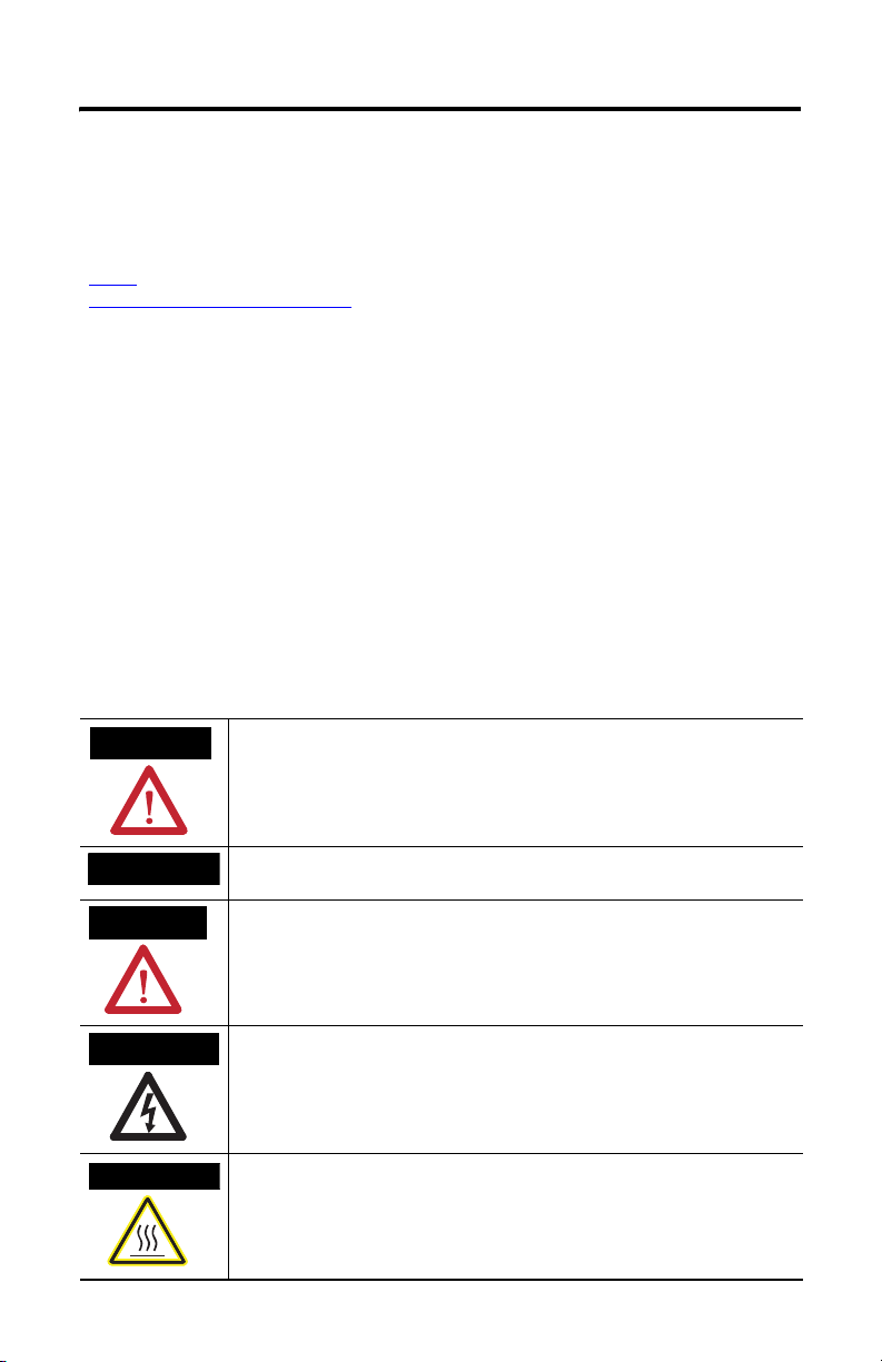
Throughout this manual, when necessary, we use notes to make you aware of safety considerations.
WARNING
IMPORTANT
ATTENTION
SHOCK HAZARD
BURN HAZARD
Identifies information about practices or circumstances that can cause an explosion in
a hazardous environment, which may lead to personal injury or death, property
damage, or economic loss.
Identifies information that is critical for successful application and understanding of
the product.
Identifies information about practices or circumstances that can lead to personal injury
or death, property damage, or economic loss. Attentions help you to identify a hazard,
avoid a hazard, and recognize the consequences.
Labels may be located on or inside the equipment, for example, a drive or motor, to
alert people that dangerous voltage may be present.
Labels may be located on or inside the equipment, for example, a drive or motor, to
alert people that surfaces may reach dangerous temperatures.
Publication 6181P-IN001I-EN-P - July 2008
Page 3

Integrated Display Computers 3
Environment and Enclosure Information
Review the information on enclosures and environments before installing the
product.
ATTENTION
Environment and Enclosure
This equipment is intended for use in a Pollution Degree 2 industrial environment, in
overvoltage Category II applications (as defined in IEC publication 60664-1), at altitudes
up to 2000 meters without derating.
This equipment is considered Group 1, Class A industrial equipment according to
IEC/CISPR Publication 11. Without appropriate precautions, there may be potential
difficulties ensuring electromagnetic compatibility in other environments due to
conducted as well as radiated disturbance.
This equipment is supplied as open type equipment. UL Listed equipment need not be
mounted inside another enclosure if NEMA Type,
UL, or IEC ratings are not required, but the mounting method must limit the tilt of the
product to +/- 30 degrees from vertical. Examples include articulated arm, table-top
stand, wall mount or other means having sufficient mechanical stability and which is
secured to the mounting surface. Units that are not rack-mount ship with a gasketed
bezel to meet specified NEMA Type, UL, and IEC ratings only when mounted in an
enclosure with equivalent ratings. Subsequent sections of this publication may contain
additional information regarding specific enclosure type ratings required to comply with
certain product safety certifications.
In addition to this publication, see:
• Industrial Automation Wiring and Grounding Guidelines, Allen-Bradley
publication 1770-4.1, for additional installation requirements.
• NEMA Standards publication 250 and IEC publication 60529, as applicable,
for explanations of the degrees of protection provided by different types
of enclosure.
Publication 6181P-IN001I-EN-P - July 2008
Page 4

4 Integrated Display Computers
European Union Directive Compliance
This product meets the European Union Directive requirements when installed
within the European Union or EEA regions and has the CE mark. A copy of the
Declaration of Conformity is available at the Rockwell Automation / Allen-Bradley
website: www.ab.com/certification
ATTENTION
ATTENTION
This product is intended to operate in an industrial or control room environment,
which utilizes some form of power isolation from the public low voltage mains.
Some computer configurations may not comply with the EN 61000-3-2 Harmonic
Emissions standard as specified by the EMC Directive of the European Union. Obtain
permission from the local power authority before connecting any computer
configuration that draws more than 75 watts of AC power directly from the public
mains.
To comply with EN 55024 and EN 61000-6-2, the Ethernet port LAN cable must be
less than 30 m (98.42 ft) and used only indoors, not exit the building at any point. All
other I/O cables must be less than 3 m (9.842 ft) and used only indoors.
Publication 6181P-IN001I-EN-P - July 2008
Page 5

Integrated Display Computers 5
Operating Systems
The computers are shipped with one of these operating systems:
• Windows 2000 Professional, Service Pack 4 with Update Rollup 1
• Windows XP Professional, Service Pack 2b
No operating system updates have been applied to the factory image beyond the
service packs.
For your convenience, the I386 source directory for Microsoft Windows is on the
system drive of your computer off the root directory, C:\1386. This allows for easy
removal and addition of Windows components.
Computers with rotating-media hard drives include a recovery partition on the
system drive containing the original factory image. You can use the supplied System
Accessories/Cloning CD to restore the operating system from the recovery partition,
create a new recovery image, and create bootable external recovery media.
Refer to the Cloning Utility documentation, publication 6000-TD001, for
instructions. You can view or download publications at
http:\\literature.rockwellautomation.com
Computers with solid state drives have been customized to accommodate the
unique properties of the solid state drive. Some of the pre-installed customizations
include:
• No paging file
• System restore set to zero and disabled
• DLLCACHE directory emptied
Computers with solid state hard drives do not contain a recovery partition. If
additional drive space is required, copy the I386 directory to external media; then
delete the I386 directory from C:\I386, which is approximately 400 MB.
To obtain the original factory image on bootable external recovery media, which
also includes the I386 source directory, contact your local technical support center.
Multilingual User Interface CD Pack
The Microsoft Multilingual User Interface (MUI) CD Pack contains a collection of
different language sets that can be installed into the operating system. MUI packs
are available for all Windows XP operating systems and provide a localized start
menu and system icons support.
The instructions for installing MUI languages on your computer are supplied with
the MUI CD Pack.
Publication 6181P-IN001I-EN-P - July 2008
Page 6

6 Integrated Display Computers
Before You Begin
Before unpacking the product, inspect the shipping carton for damage. If damage is
visible, immediately contact the shipper and request assistance. Otherwise, proceed
with unpacking.
Keep the original packing material in case you need to return the product for repair
or transport it to another location. Use both the inner and outer packing cartons to
ensure adequate protection for a unit returned for service.
Parts List
The computers are shipped with these items.
• System Accessories/Cloning CD
• Support CD
• Microsoft Multilingual User Interface (MUI) CD Pack
This CD pack is not included with computers containing the Windows 2000
operating system.
• Mounting clips, except for the 1200P Non-display computer
• AC power cord, when appropriate
• PS/2 Y-adapter cable for keyboard and mouse connection (supplied with all
6181P Series A and 6181H 1500P Series B computers)
• Installation guide and cutout template
Installation Guidelines
Follow these guidelines to make sure your product provides safe and reliable
service.
• The installation site must have sufficient power.
ATTENTION
• The enclosure must have sufficient space around air inlets and outlets to
provide the circulation necessary for cooling. Never allow air passages to
become obstructed.
Publication 6181P-IN001I-EN-P - July 2008
To maintain an electrically safe installation, the product must be connected to earth
ground when installed. Follow the appropriate grounding requirements associated with
your specific product type as described in this installation document.
Page 7

Integrated Display Computers 7
• The ambient air temperature must not exceed the maximum operating
temperature. Consider heat produced by other devices in the enclosure. You
may need a user-supplied fan, heat exchanger, or air conditioner to meet
this condition.
TIP
IMPORTANT
• The humidity of the ambient air must not exceed specified limits.
• In dry environments, static charges build up readily. Proper grounding of the
equipment through the AC power cord helps to reduce static discharges,
which may cause shocks and damage electronic components.
• The enclosure or cover must remain in place at all times during operation.
The cover provides protection against high voltages inside the product and
inhibits radio-frequency emissions that might interfere with other equipment.
Hot air rises. The temperature at the top of the enclosure is often higher than the
temperature in other parts of the enclosure, especially if air is not circulating.
The product can operate at a range of extremes. However, the life span of any electronic
device is shortened if you continuously operate the product at its highest rated
temperature.
Install the Computer
There are various ways you can install the computer.
• Panel mount
• Bench or tabletop
Review each mounting type and product dimensions before installation.
Panel Mounting
Before installing the computer in a panel, review the following information.
• Required tools
• Panel mounting guidelines
• Panel cutout dimensions
• Product dimensions
Publication 6181P-IN001I-EN-P - July 2008
Page 8

8 Integrated Display Computers
Required Tools
The following tools are required for product installation.
• Panel cutout tools
• #2 Phillips screwdriver
Panel Mounting Guidelines
Observe these guidelines when installing the unit in a panel.
• Confirm that there is adequate space within the panel enclosure.
• Cut supporting panels to specifications before installation. Take precautions
so that metal cuttings do not enter components already installed in panel.
• Supporting panels must be at least 14 gauge to ensure proper sealing against
water and dust and to provide proper support. The mounting hardware
supplied accommodates panels up to 6.25 mm (0.25 in) thick.
ATTENTION
Failure to follow these guidelines may result in personal injury or damage to the panel
components.
Panel Cutout Dimensions
Computer Model Cutout Dimensions (H x W)
1200P 254.0 x 324.0 mm (10.0 x 12.76 in)
1500P 285.0 x 386.6 mm (11.24 x 15.22 in)
1700P 329.5 x 424.0 mm (12.97 x 16.69 in)
Mount the Computer in a Panel
Follow these steps to mount the monitor in a panel.
1. Remove power from the panel.
ATTENTION
Remove all electrical power from the panel before making cutout.
Make sure the area around the panel cutout is clear.
Failure to follow these warnings may result in personal injury or damage to the panel
components.
Publication 6181P-IN001I-EN-P - July 2008
Page 9

Integrated Display Computers 9
2. Cut an opening in the panel using the appropriate panel cutout dimensions.
3. Make sure the sealing gasket is properly positioned on the computer.
This gasket forms a compression type seal. Do not use sealing compounds.
4. Place the computer in the panel cutout.
5. Slide the mounting clips into the slots on the top, bottom and sides of the
computer.
6. Gradually tighten the clips one at a time around the bezel using the specified
sequence.
The sequence begins with the center clips and continues to the corner clips.
Repeat this process at least three times until the clips are hand-tight and the
gasket is compressed uniformly against the panel.
1109
5
Torque Sequence
4
278
3
6
Publication 6181P-IN001I-EN-P - July 2008
Page 10

10 Integrated Display Computers
7. Tighten mounting clips to a torque of 1.4 Nm (12 lb•in) using the sequence
in the previous step.
Do not over-tighten.
ATTENTION
Tighten the mounting clips to the specified torque to provide a proper seal and
prevent damage to the product. Rockwell Automation assumes no responsibility for
water or chemical damage to the product or other equipment within the enclosure
because of improper installation.
Bench or Tabletop Mounting
You can mount the 1500P or 1700P computer on a bench or tabletop using an
optional adapter (6189V-MBA). The back of the computer has four mounting points
that are VESA 100 mm standard.
Mounting Guidelines
Observe these guidelines when installing the computer on an arm.
• The mounting surface must be strong enough to support both the computer
and the mounting hardware.
• The mounting arm must be strong enough to support the computer. The arm
must meet VESA FPMPMI 100 mm standards.
• The mounting location must provide clearance for mounting and positioning
the adjustable unit and routing cables.
• Per UL Listing restrictions, the product must be mounted with a tilt of +/- 30°
or less from vertical.
Mount the Computer on a Bench or Tabletop
1. Mount the arm to the benchtop or tabletop using screws, bolts, or clamps so
the computer cannot tip.
2. Place the computer over the arm, and insert four M4 x 0.7 screws through
the arm brackets and into the back cover of the computer.
3. Tighten the screws.
Publication 6181P-IN001I-EN-P - July 2008
Page 11

Integrated Display Computers 11
Product Dimensions
Product dimensions for each computer model are given in mm (in).
1200P Integrated Display Computer
320 [12.60]
281 [11.079]
349 [13.75]
279 [10.99]
1200P Non-display Computer
281 [11.079]
343 [13.51]
317.5 [12.51]
8.00 [0.31]
175.9 [6.93]
251 [9.89]
144.9 [5.70]
2 (.078)
240 [9.46]
190.5 [7.51]
239.1 [9.41]
Publication 6181P-IN001I-EN-P - July 2008
Page 12

12 Integrated Display Computers
1500P Integrated Display Computer
383.60 [15.10]
13.20 [0.52]
309.00 [12.17]
410.00 [16.14]
1700P Integrated Display Computer
356.00 [14.02]
422.00
8.00 [0.31]
282.60 [11.13]
99.9 [3.93]
14.00 [0.52]
328.00 [12.91]
452.00 [17.80]
Publication 6181P-IN001I-EN-P - July 2008
8.00 [0.31]
101.6 [4.00]
Page 13

Integrated Display Computers 13
Connect the Keyboard and Mouse
You can connect a keyboard to the PS/2 port on the bottom of the computer. You
can connect both a keyboard and mouse to this port using the Y-adapter cable that
ships with the 6181P Series A computers.
1500P - Series A
1500P - 6181H Series A and B
1700P - Series A
The 6181P Series B and later computers have separate PS/2 ports for the keyboard
and mouse.
1200P - Series B and C
1500P - Series B and C
1700P - Series B and C
Publication 6181P-IN001I-EN-P - July 2008
Page 14

14 Integrated Display Computers
Connect AC Power
A standard IEC 320 power cord provides power to the computer. The power supply
input accepts 120/240V AC. The power supply is autoswitching.
Operate the computer in an industrial or control room environment, which uses
some form of power isolation from the public low voltage mains.
1200P only:
You many need to remove the AC retainer
clip before installing the unit in a panel.
Reattach the clip after installing the unit.
ATTENTION
Connect the AC power cord to a power source with an earth ground to prevent electrical
shock. Failure to follow this warning could result in electrical shock.
The computer circuit should have its own disconnect. Use an Uninterruptible Power
Source (UPS) to protect against unexpected power failure or power surges.
Always shut down the operating system before removing power to minimize performance
degradation and operating system failures.
Publication 6181P-IN001I-EN-P - July 2008
Page 15

Integrated Display Computers 15
Connect DC Power
The 1200P computers with an integrated 24V DC power supply support these
electrical ratings:
• 18 to 32V DC (24V DC nominal)
• 6.3 A at 24V DC
The power supply is internally protected against reverse polarity.
ATTENTION
Use a Class 2/SELV (Safety Extra-Low Voltage) isolated and ungrounded power supply as
input power to the workstation. This power source provides protection so that under
normal and single fault conditions, the voltage between the conductors and Functional
Earth/Protective Earth does not exceed a safe value.
1. Secure the DC power wires to the terminal block screws.
2. Secure the ground wire to the GND terminal screw.
3. Apply 24V DC power to the terminal.
GND
(Safety Ground)
V- (DC Negative)
V-
V+
V+ (DC Positive)
GND (Safety Ground Alternate Connection)
ATTENTION
Connect the product to earth ground using a 1.31 mm2 (16 AWG) or larger external wire.
The ground wire should have green insulation with a yellow stripe for easy identification.
Publication 6181P-IN001I-EN-P - July 2008
Page 16

16 Integrated Display Computers
Connect to the Network
The computer connects to the Ethernet network using CAT5 or CAT5E twisted pair
Ethernet cabling with RJ45 connectors.
IMPORTANT
To prevent performance degradation of Ethernet communication, do not subject the
computer or cables to extreme radiated or conducted high-frequency noise.
Proper cable routing and power conditioning is required to ensure reliable Ethernet
communication in industrial environments. Rockwell Automation recommends that you
route all Ethernet cabling through dedicated metal conduits. Installing ferrite bead filters
at the cable ends may also improve reliability.
Replace the Battery
The computer contains a lithium battery to maintain CMOS settings and the
real-time clock. The battery is in a battery holder on the computer’s CPU board.
Replace this battery as needed with a Panasonic battery, part number CR2032, or
equivalent.
WARNING
To avoid the danger of explosion, only replace the battery with part number CR2032 or a
recommended equivalent. Dispose of used batteries according to the manufacturer’s
instructions.
Backlight Disposal
ATTENTION
The backlight assembly in this unit contains mercury. At the end of its life, this equipment
should be collected separately from any unsorted municipal waste.
Publication 6181P-IN001I-EN-P - July 2008
Page 17

Integrated Display Computers 17
Ship or Transport the Product
If you need to ship your product via common carrier or otherwise transport it to
another location, you must first uninstall the product and place it in its original
packing material
.
ATTENTION
Do not ship or transport the product when it is installed in a machine, panel or rack.
Doing so may cause damage to the product. You must uninstall the product and place in
its original packing material before shipping. Rockwell Automation is not responsible for
damage incurred to a product that is shipped or transported while installed in a machine,
panel or rack.
Publication 6181P-IN001I-EN-P - July 2008
Page 18

18 Integrated Display Computers
Specifications
6181P and 6181F Integrated Display Computers
Specification Value
Display description Active Matrix Color TFT
Touchscreen, optional Resistive antiglare
Display size
1200P
1500P
1700P
Display area (W x H)
1200P
1500P
1700P
Resolution, native
1200P
1500P
1700P
Response time 15 ms (typical)
Electrical Specifications
12.1 in
15.0 in
17.0 in
246 x 185 mm (9.7 x 7.3 in)
305 x 229 mm (12 x 9 in)
338 x 270 mm (13.3 x 10.7 in)
800 x 600, 256K colors
1024 x 768, 256K colors
1280 X 1024, 16.7M colors
Specification Value
Input voltage, ac 90…264V ac, autoswitching
Line frequency 47…63 Hz
Power consumption, AC
1200P, 1500P, 1700P
1200P (6181P-2X Non-display)
Input voltage, DC
1200P and
1200P (6181P-2X Non-display)
Power consumption, DC
1200P
1200P (6181P-2X Non-display)
(1)
Applies to 6181P computers with rotating media only.
(1)
(1)
150 VA (1.5 A @ 100 V rms, 0.63 A @ 240 V rms)
140 VA (1.4 A @ 100 V rms, 0.58 A @ 240 V rms)
18…32 V dc
150 W
140 W
Publication 6181P-IN001I-EN-P - July 2008
Page 19

Integrated Display Computers 19
Mechanical Specifications
Specification Value
Weight
1200P
1500P
1700P
Dimensions (H x W x D), approx.
1200P
1500P
1700P
Cutout dimensions (H x W), approx.
1200P
1500P
1700P
9.2 kg (21 lb)
10 kg (23 lb)
12.6 kg (28 lb)
279 x 349 x 176 mm (10.99 x 13.75 x 6.93 in)
309 x 410 x 109 mm (12.17 x 16.14 x 4.29 in)
356 x 452 x 110 mm (14.02 x 17.80 x 4.32 in)
254 x 324 mm (10.00 x 12.76 in)
285 x 386.6 mm (11.24 x 15.22 in)
329.5 x 424 mm (12.97 x 16.69 in)
Environmental Specifications
Specification Value
Temperature, operating 0…50 °C (32…122 °F)
Temperature, storage -20…60 °C (-4 to 140 °F)
Relative humidity 10%…90% without condensation
Shock, operating
Shock, nonoperating
Vibration, operating
Computers, rotating hard drive
Computers with solid state drive
Vibration, nonoperating
15 g (1/2 sine, 11 ms)
30 g (1/2 sine, 11 ms)
1.0 g peak (10…500 Hz)
1.5 g peak (10…500 Hz)
2.0 g peak (10…500 Hz)
Enclosure ratings NEMA Type 1, 12, 4, IEC IP66
NEMA Type 4X for stainless steel units only
(1)
Applies to panel-mounted products only.
(2)
The floppy drive and optical disc drive are considered maintenance devices. You should not operate computers with these
devices in environments with the shock and vibration levels listed.
(1) (2)
(1)
(1) (2)
(1) (2)
(1)
Publication 6181P-IN001I-EN-P - July 2008
Page 20

Certification
c-UL-us UL 60950 recognized component, c-UL 950 recognized component, or
CE Marked for all applicable directives
RoHS compliant
C-Tick Australian Radiocommunications Act, compliant with:
(1)
See http://ab.com for declarations of conformity, certificates, and other certification details.
(1)
UL/c-UL listed when marked
AS/NZS CISPR 11; Industrial Emissions
Additional Resources
For additional information on the 6181P and 6181F integrated display computers,
refer to the following publications.
Resource Description
Integrated Display Computers User
Manual, publication 6181P-UM001
Cloning Utility Technical Data,
publication 6000-TD001
These publications are on the System Accessories/Cloning CD, which are shipped
with your computer. You can download electronic versions of these publications
from the Rockwell Automation website http://literature.rockwellautomation.com
Gives an overview of the system and provides procedures
to install the computer, set up computer connections,
operate the computer, and troubleshoot the computer.
Provides information on how to create and restore a backup
image of your computer’s hard drive.
.
Allen-Bradley and Rockwell Automation are trademarks of Rockwell Automation, Inc.
Trademarks not belonging to Rockwell Automation are property of their respective companies.
Publication 6181P-IN001I-EN-P - July 2008 PN-29060
Supersedes Pub lication 6181P-IN001H-E N-P - July 2007 Copyright © 20 08 Rockwell Automatio n, Inc. All rights reser ved. Printed in the U.S.A.
 Loading...