

Page 1

Installation Instructions
6181 Industrial Computer
6181 Industrial Computer
6181 Industrial Computer6181 Industrial Computer
English ................................................................... Page 2
Ordinateur industriel 6181
Ordinateur industriel 6181
Ordinateur industriel 6181Ordinateur industriel 6181
Français ............................................................... Page 24
Industriecomputer 6181
Industriecomputer 6181
Industriecomputer 6181Industriecomputer 6181
Deutsch ............................................................... Seite 46
Ordenador Industrial 6181
Ordenador Industrial 6181
Ordenador Industrial 6181Ordenador Industrial 6181
Español ............................................................ Página 68
Computer industriale 6181
Computer industriale 6181
Computer industriale 6181Computer industriale 6181
Italiano .............................................................. Pagina 90
Computador Industrial 6181
Computador Industrial 6181
Computador Industrial 6181Computador Industrial 6181
Português ........................................................ Página 112
Page 2

Installation Instructions
6181 Industrial Computer
6181 Industrial Computer
6181 Industrial Computer6181 Industrial Computer
Chapter Objective
This chapter describes installation of the 6181 Industrial Computer
including how to install the 6181 Computer in a panel using mounting
studs or clips.
European Union Compliance
The 6181 Computer meets the European Union Directive requirements
when installed within the European Union or EEA regions and has the CE
mark. A copy of the Declaration of Conformity is available at the
Rockwell Automation/Allen-Bradley Internet site: www.ab.com
ATTENTION: The 6181 Computer is intended to
operate in an industrial or control room environment,
which utilizes some form of power isolation from the
public low voltage mains. Some configurations may not
comply with the EN 61000-3-2 Harmonic Emissions
standard as specified by the EMC Directive of the
European Union. Obtain permission from the local power
authority before connecting any configuration that draws
more than 75 watts of AC power directly from the public
mains.
Publication 6181-IN002C-MU-P
Page 3

6181 Industrial Computer 3
Environmental Considerations
Mount the 6181 Computer in a panel or enclosure to protect the internal
circuitry. Versions with a gasketed bezel meet NEMA Type 1, 12, 13 and 4
(Indoor use) and IEC IP54, IP65 only when mounted in a panel or
enclosure having an equivalent rating. The non-display version does not
have a gasket and has a NEMA Type 1 and IEC IP2X rating.
Allow enough room within the enclosure for adequate ventilation. Also
consider heat produced by other devices in the enclosure. The ambient
temperature around the 6181 Computer must be maintained between 5°
and 50 °C (41° to 122 °F). The 6181 Computer is intended for use in
Pollution Degree 2 environments.
Make sure you provide provisions for accessing the back and side panels
of the 6181 Computer to install/remove components and to access the
floppy disk drive.
ATTENTION: The 6181 Industrial Computer is designed
for vertical panel-mount installation. Do not mount the
6181 Computer with DVD-ROM or CD-R/W option with
an angle more than 5 degrees from vertical. This may
cause operational problems with the DVD-ROM or CDR/W drive, and may result in damage to your media.
Publication 6181-IN002C-MU-P
Page 4

4 6181 Industrial Computer
Mounting Hardware
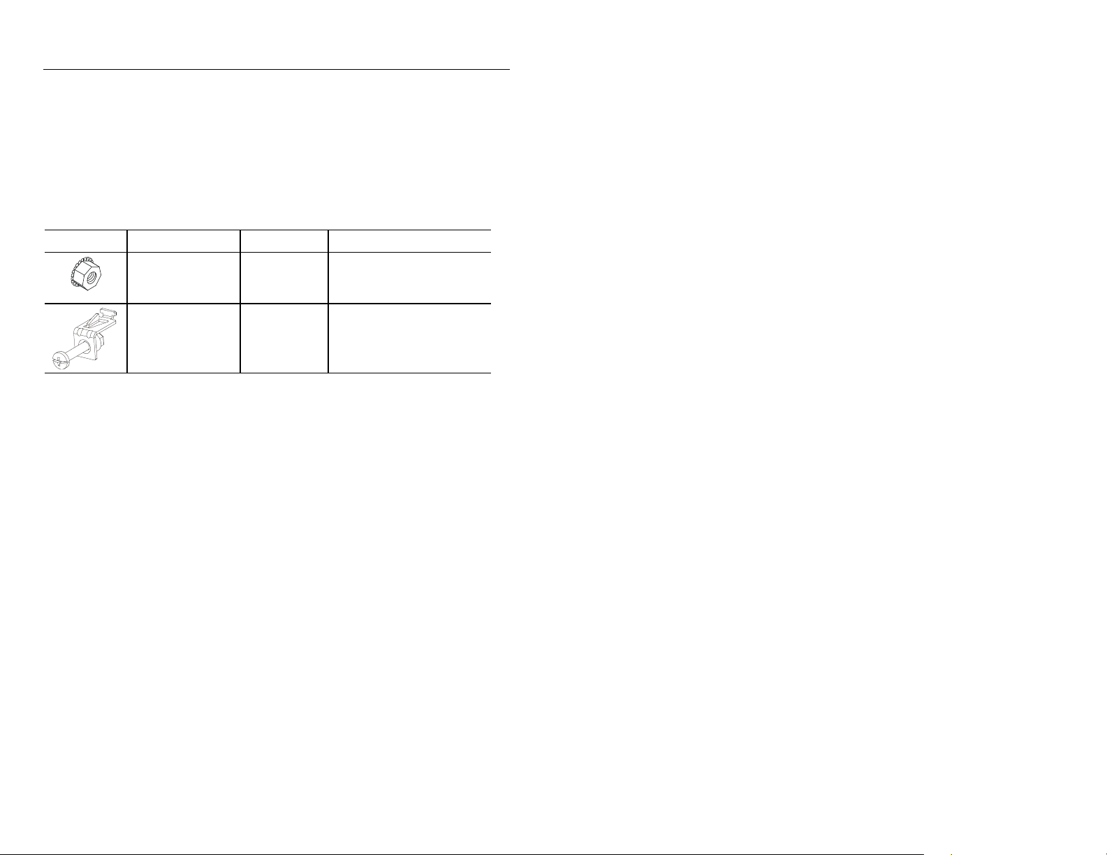
The 6181 Computer is shipped with the following mounting hardware:
Table A
Mounting Hardware
Item Description Quantity Use For
Self-locking nuts
(#10-32)
Mounting clips 6 Panel or enclosure
10
(8 required)
Panel or enclosure
mounting
mounting
Tools Required
In addition to the tools required to make the cutout, you will need the
following tools:
For Mounting Studs:
3/8 inch socket
6 inch (15 cm) extension rod (minimum)
Socket driver (in/lb. torque wrench recommended)
Ruler
For Mounting Clips:
Flat blade screwdriver
Ruler
Publication 6181-IN002C-MU-P
Page 5
6181 Industrial Computer 5
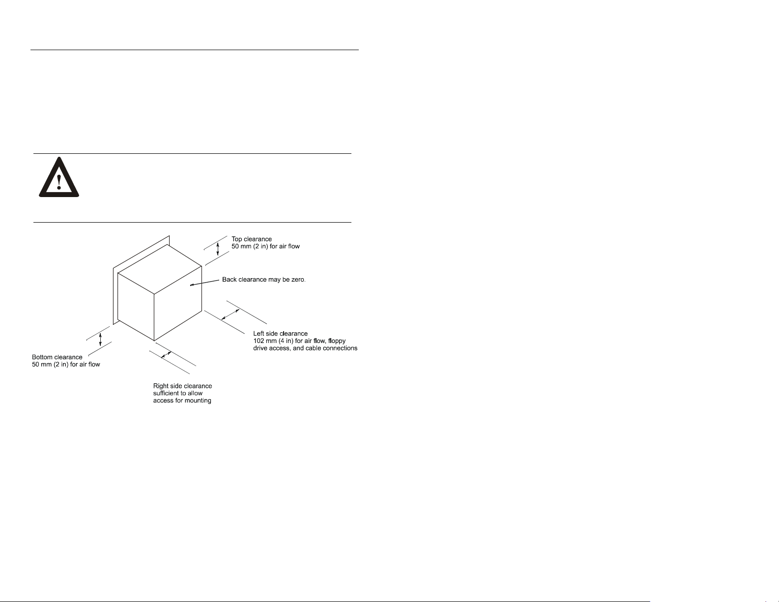
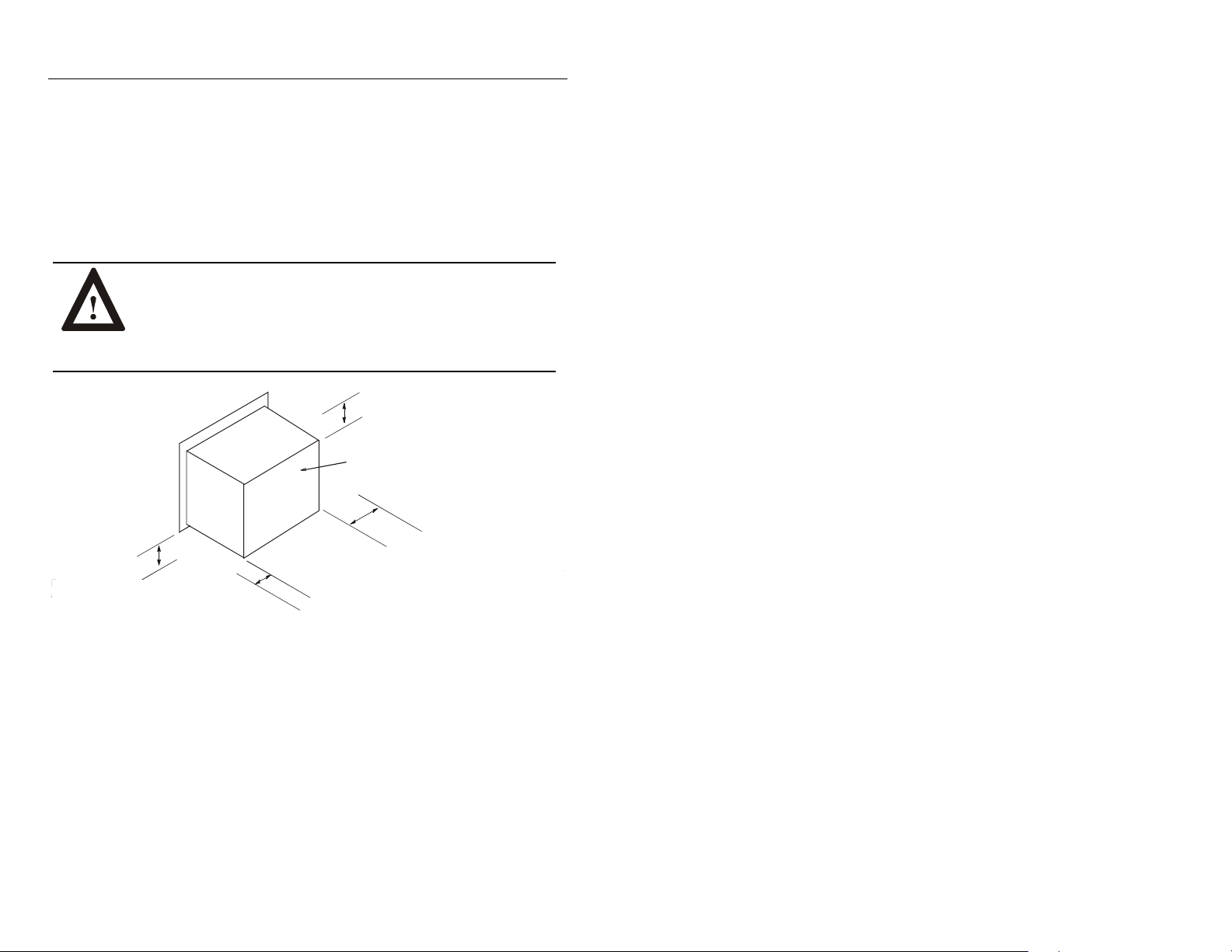
Mounting Clearances
Allow adequate space for mounting, air flow, and maintenance. The figure
below shows recommended minimum clearances to other components
within the rack or enclosure.
ATTENTION: The 6181 Computer should not be
operated within a confined space of the dimensions
shown below unless adequate ventilation or other cooling
methods are used to lower the air temperature within the
enclosure.
Publication 6181-IN002C-MU-P
Page 6
6 6181 Industrial Computer
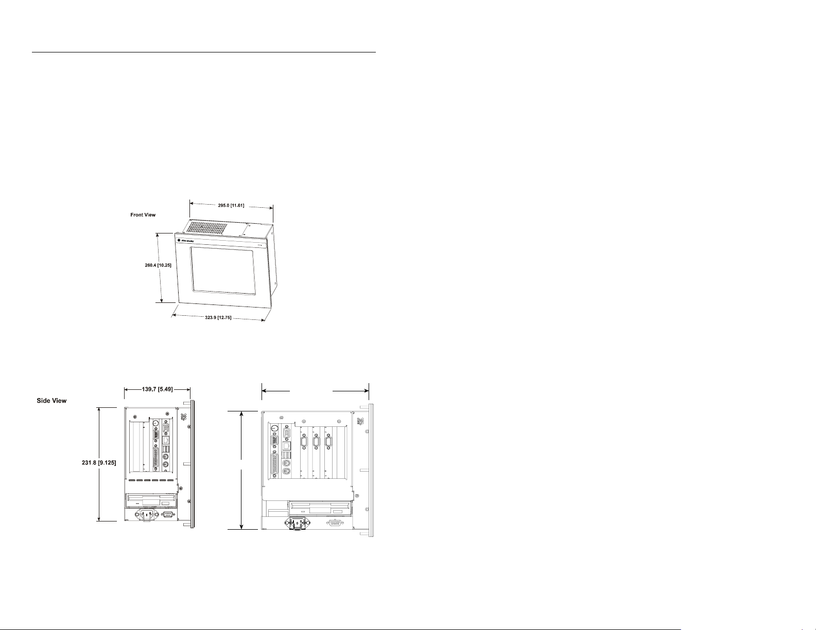
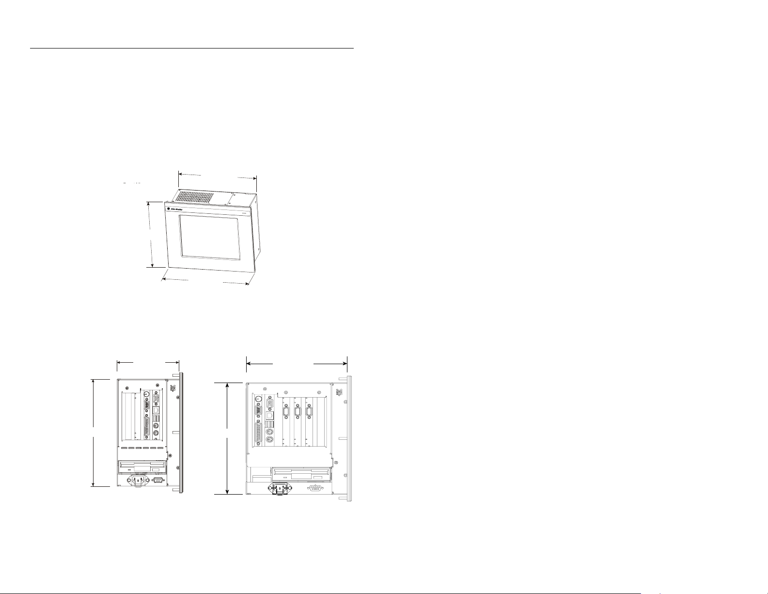
Mounting Dimensions
The following figures show the mounting dimensions for the 6181
Computer.
10.4 in. Version with Display
2-Slot Version 4-Slot Version
Publication 6181-IN002C-MU-P
181.71 [7.154]
231.55 [9.116]
Page 7
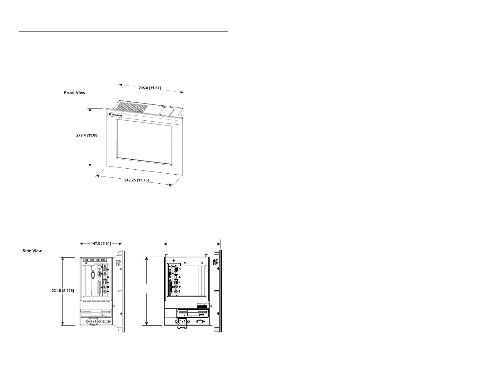
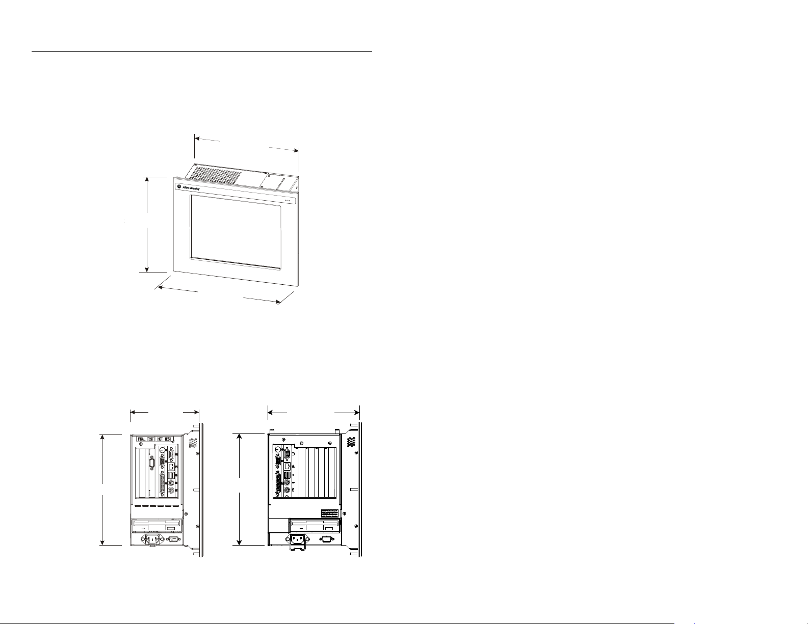
12.1 in. Version with Display
2-Slot Version (Side View) 4-Slot Version (Side View)
6181 Industrial Computer 7
189.64 [7.466]
231.55 [9.116]
Publication 6181-IN002C-MU-P
Page 8
8 6181 Industrial Computer
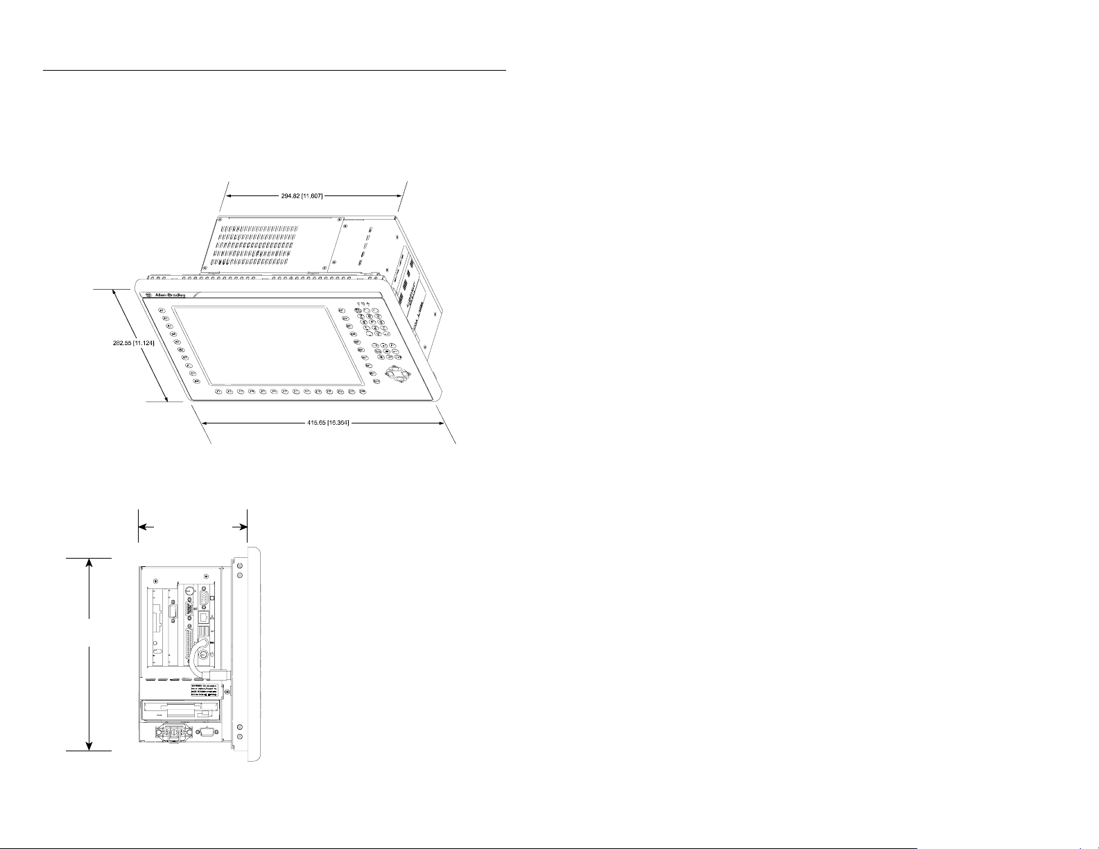
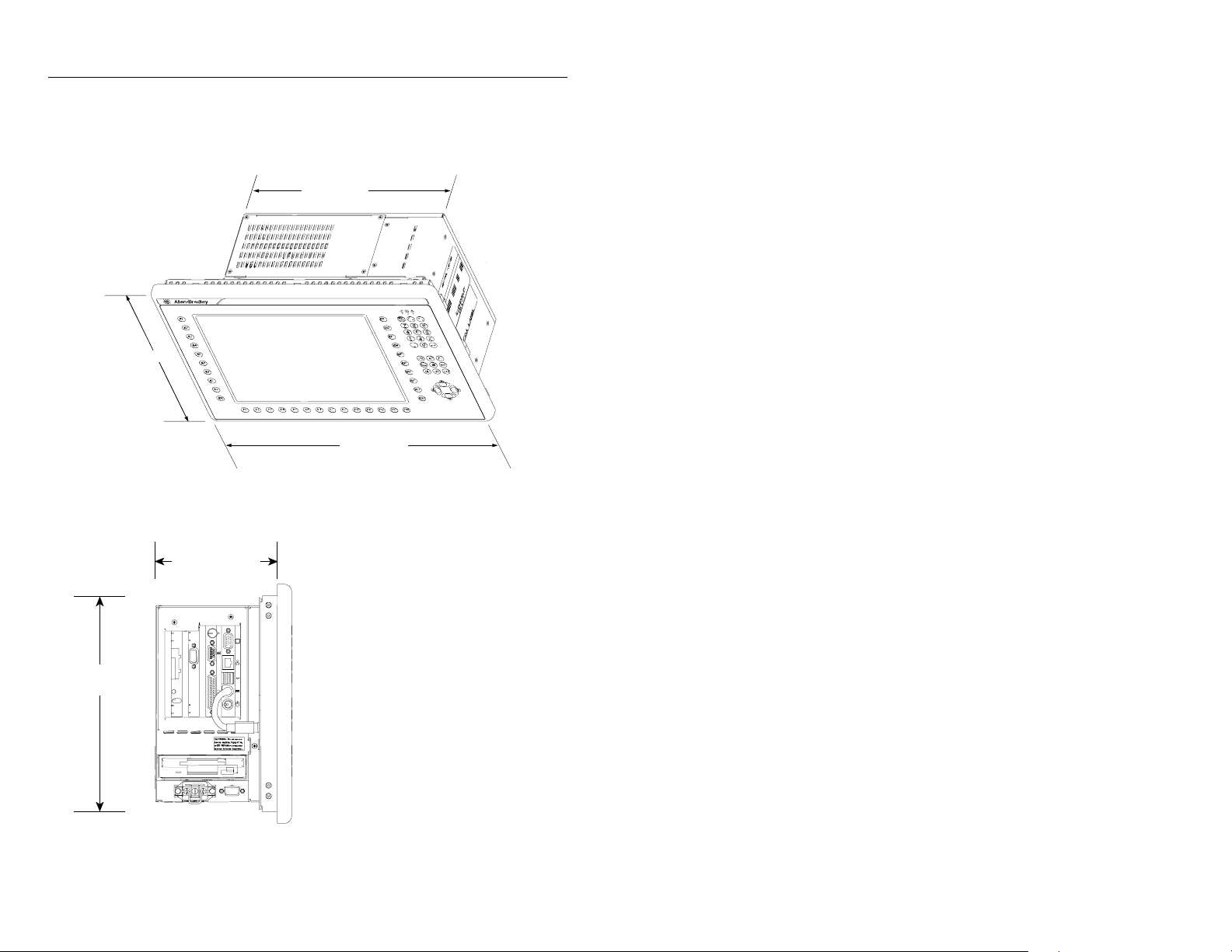
12.1 in. Version with Keypad and Display
2-Slot Version (Side View) 4-Slot Version
143.34 [5.643]
254.76 [10.030]
Publication 6181-IN002C-MU-P
Height: 254.76 [10.030]
Depth: 173.02 [6.811]
Page 9
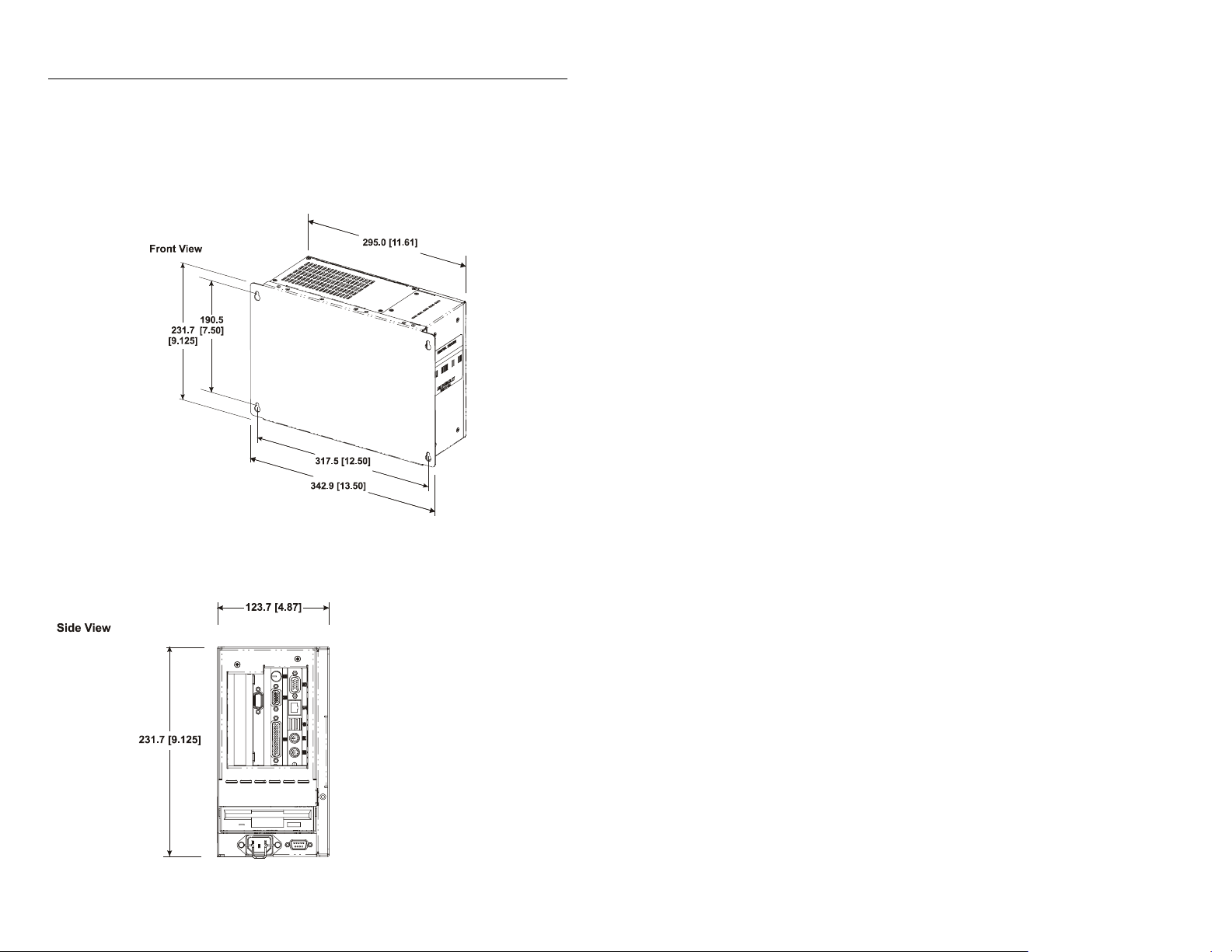
Non-Display Version
6181 Industrial Computer 9
2-Slot Version 4-Slot Version
Height: 231.7 [9.125]
Depth: 153.44 [6.041]
Publication 6181-IN002C-MU-P
Page 10
10 6181 Industrial Computer
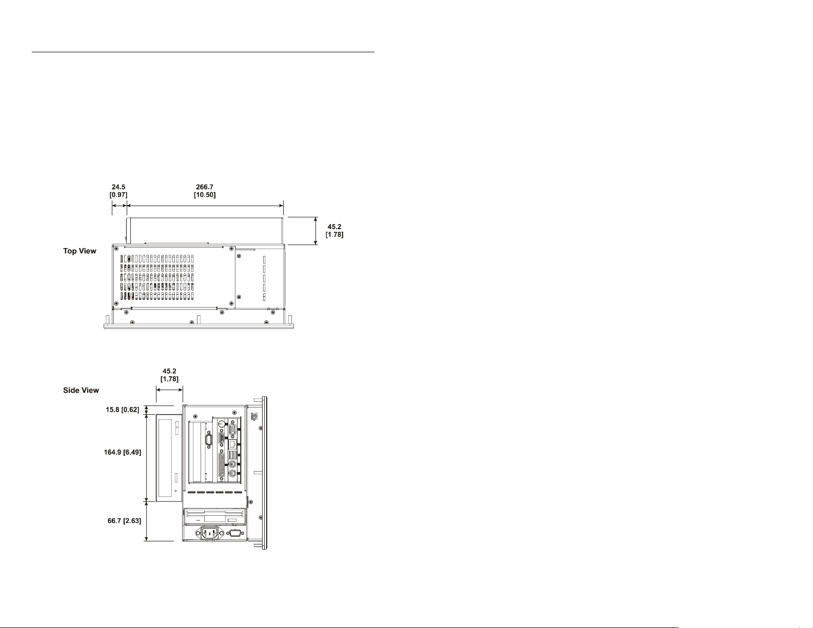
Mounting Dimensions – with Expansion Bay Option
The following figures show the mounting dimensions for the 6181
Computer with expansion bay option installed. The expansion bay option
is valid for any 6181 enclosure option.
Publication 6181-IN002C-MU-P
Page 11
6181 Industrial Computer 11
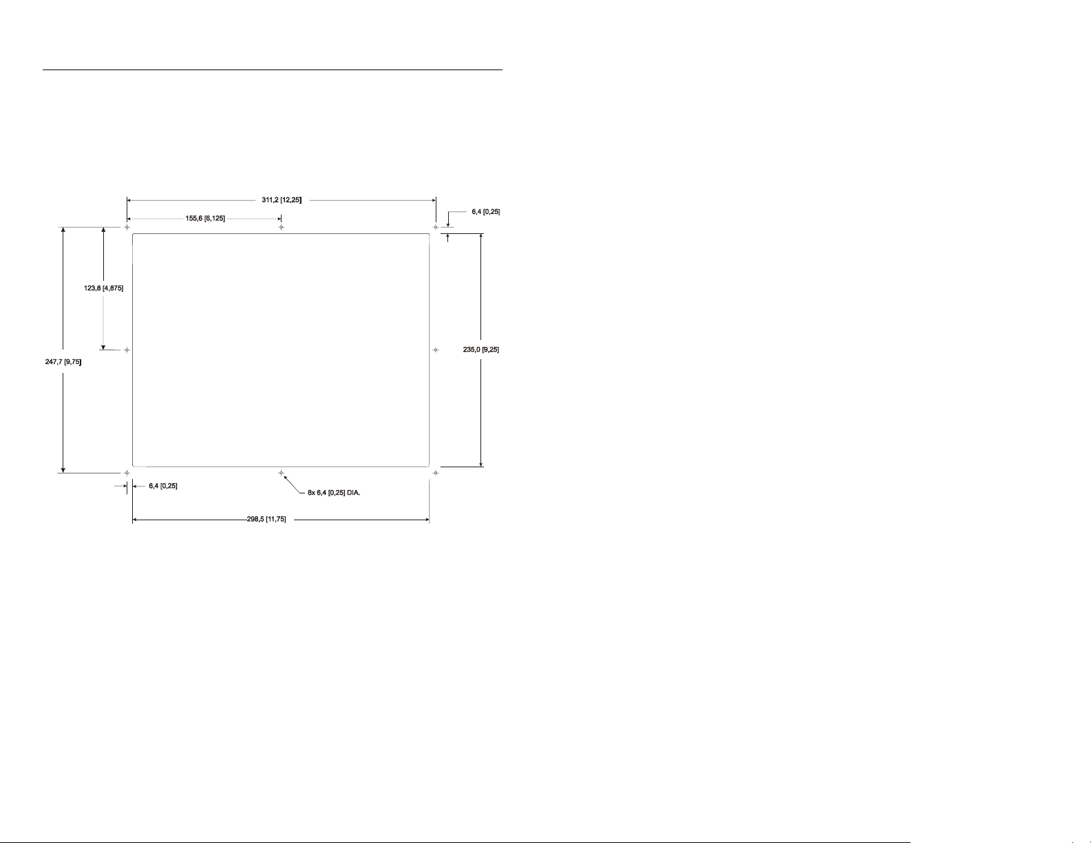
10.4 in. Mounting Cutout
The following figure provides the dimensions for making the panel or
enclosure cutout for the 10.4 in. 6181 Computer.
Publication 6181-IN002C-MU-P
Page 12
12 6181 Industrial Computer
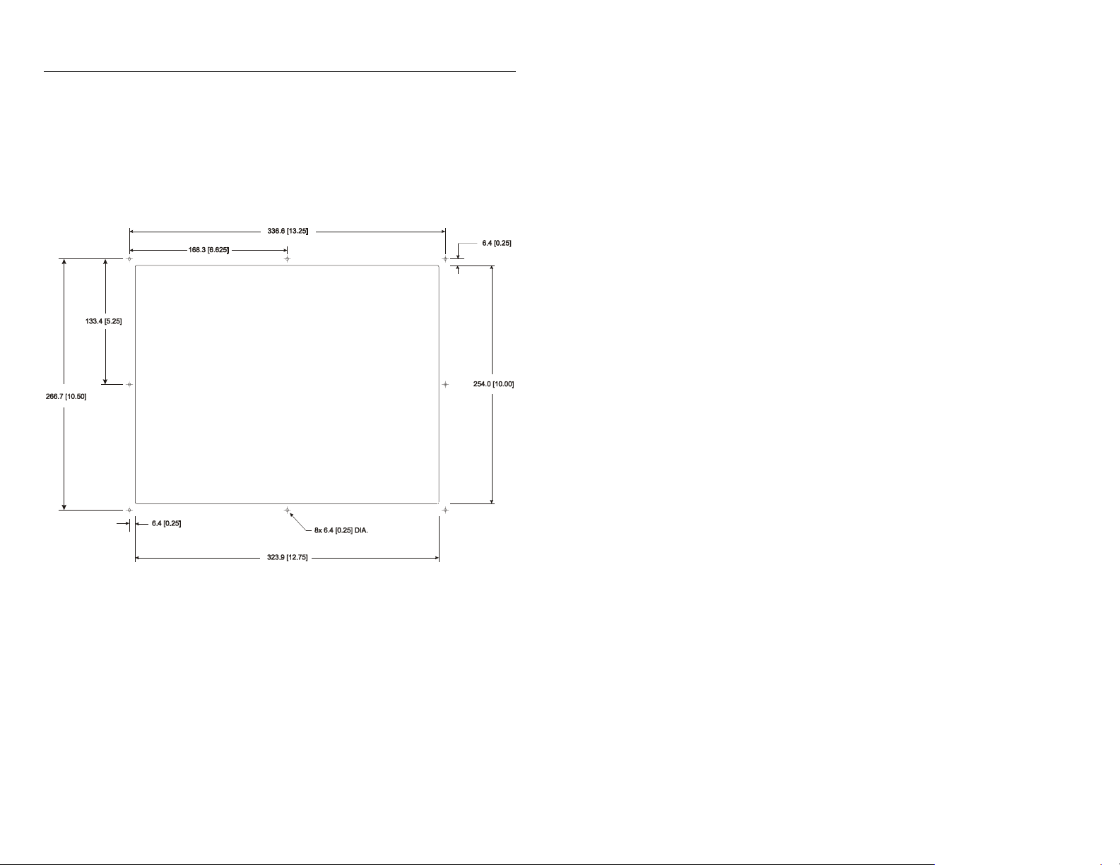
12.1 in. Mounting Cutout
The following figure provides the dimensions for making the panel or
enclosure cutout for the 12.1 in. 6181 Computer.
Publication 6181-IN002C-MU-P
Page 13
6181 Industrial Computer 13
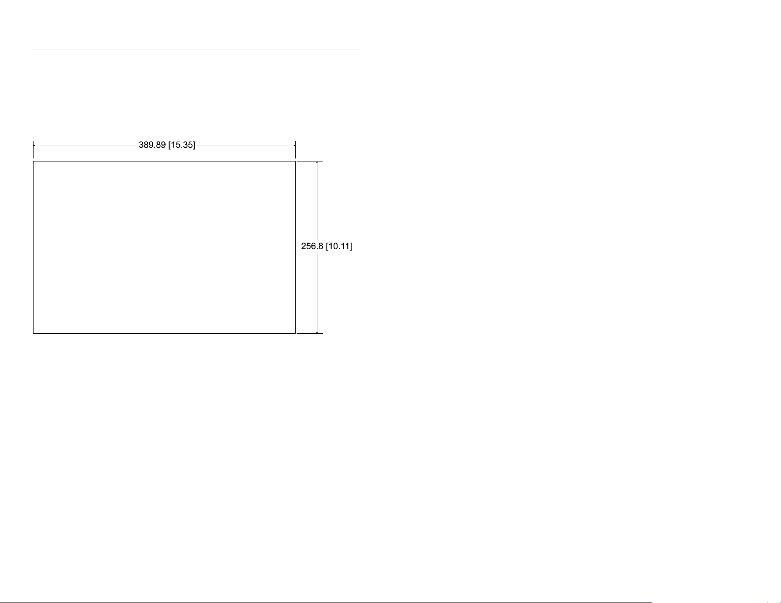
12.1 in. Keypad Mounting Cutout
The following figure provides the dimensions for making the panel or
enclosure cutout for the 12.1 in. 6181 Computer with keypad.
Publication 6181-IN002C-MU-P
Page 14

14 6181 Industrial Computer
Panel Mounting with Mounting Studs
To install the 6181 Computer in a panel using 8 mounting studs:
ATTENTION: Disconnect all electrical power from the
panel before making cutout.
Make sure the area around the panel cutout is clear.
Take precautions so that metal cuttings do not enter any
components that are already installed in the panel.
Failure to follow these warnings may result in personal
injury or damage to the panel components.
1. Cut an opening in the panel using the appropriate panel cutout
dimensions provided on pages 11 or 12. Carefully drill eight 6.4 mm
(0.25 in.) holes for the mounting studs as indicated.
2. Make sure the sealing gasket is properly positioned on the terminal.
This gasket forms a compression type seal (NEMA Type 4). Do not
use sealing compounds.
3. Place the 6181 Computer in the panel cutout aligning the studs with
the mounting holes.
4. Install the 8 self-locking nuts hand tight.
Publication 6181-IN002C-MU-P
Page 15
6181 Industrial Computer 15
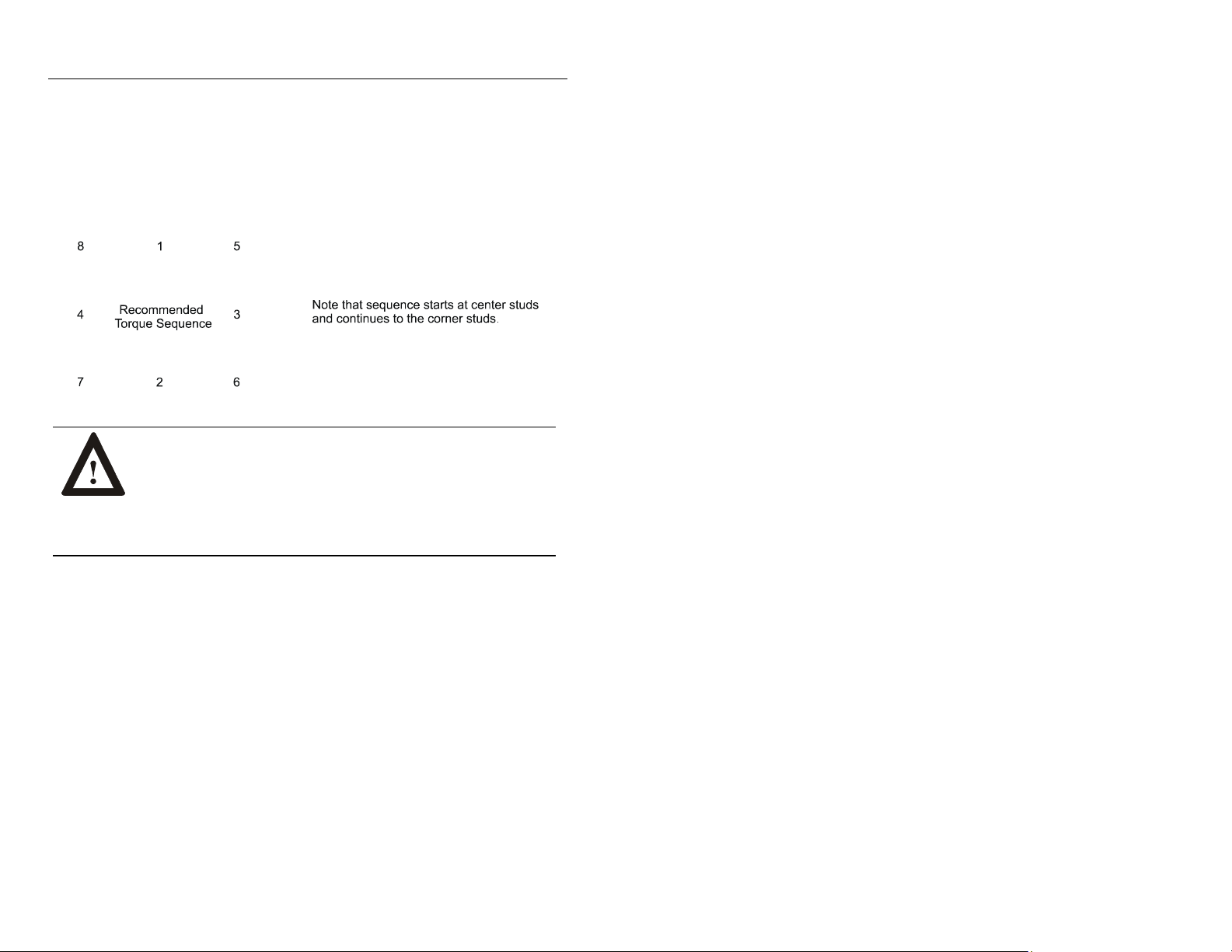
5. Alternately tighten the self-locking nuts (use 3/8 inch socket) until the
6181 Computer is held firmly against the panel (see recommended
tightening sequence below). The amount of torque required increases
significantly as the gasket reaches the proper compression. Tighten
nuts to a torque of 2.7 N-m (24 in-lbs).
ATTENTION: Tighten mounting nuts to a torque of
2.7 N-m (24 in-lbs) to provide a proper seal and prevent
damage to the 6181 Computer. Rockwell Automation
assumes no responsibility for water or chemical damage
to the terminal or other equipment within the enclosure
because of improper installation.
Publication 6181-IN002C-MU-P
Page 16

16 6181 Industrial Computer
Panel Mounting with Mounting Clips
To install the 6181 Computer in a panel using mounting clips:
ATTENTION: Disconnect all electrical power from the
panel before making cutout.
Make sure the area around the panel cutout is clear.
Take precautions so that metal cuttings do not enter any
components that are already installed in the panel.
Failure to follow these warnings may result in personal
injury or damage to the panel components.
1. Cut an opening in the panel using the appropriate panel cutout
dimensions provided on page 13.
2. Make sure the 6181 Computer sealing gasket is properly positioned on
the terminal. This gasket forms a compression type seal. Do not use
sealing compounds.
3. Place the 6181 Computer in the panel cutout.
Publication 6181-IN002C-MU-P
Page 17
6181 Industrial Computer 17
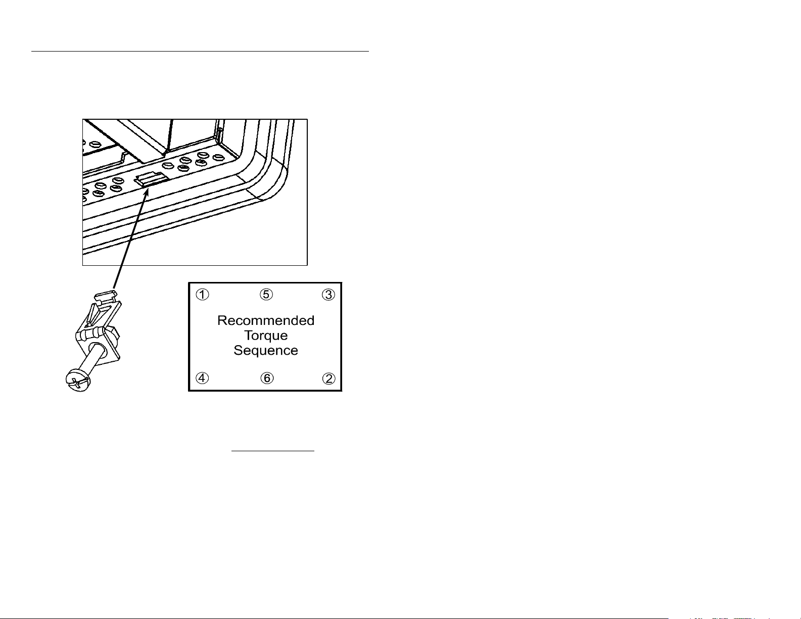
4. Install the mounting clips. The mounting clips slide into the slots on
the top and bottom of the 6181 Computer.
Mounting
Clip
5. Gradually tighten the clips one at a time around the bezel using the
specified sequence. Repeat this process at least three times until the
clips are hand-tight and the gasket is compressed uniformly against the
panel.
6. Tighten mounting clips to a torque of 10 in–lbs (1.1 N•m) in the
sequence shown above. Do not over–tighten.
Publication 6181-IN002C-MU-P
Page 18

18 6181 Industrial Computer
ATTENTION: Tighten mounting clips to a torque of
10 in–lbs (1.1 N•m) to provide a proper seal and prevent
damage to the 6181 Computer. Rockwell Automation
assumes no responsibility for water or chemical damage
to the terminal or other equipment within the enclosure
because of improper installation.
Connecting Equipment in Hazardous Locations
Specific configurations of the are certified for Class I, Division 2, Groups
A, B, C, D, T4A temperature code, hazardous areas. When installing the
in a hazardous location, note the following safety considerations:
Installation Wiring
See the nameplate label on the computer for certifications on hazardous
locations.
ATTENTION: In Class I, Div 2 hazardous locations, the
6181 Industrial Computer must be wired per the National
Electric Code and/or Canadian Electric Code as it applies
to hazardous locations.
Connecting and Disconnecting Equipment
When installing the 6181 Industrial Computer, note the following safety
considerations:
ATTENTION: EXPLOSION HAZARD! Do not
connect or disconnect equipment while circuit is live
unless area is known to be non-hazardous.
Note:
Publication 6181-IN002C-MU-P
Do not connect or disconnect connections in the presence
of possible hazardous materials. Making or breaking these
connections may cause a spark.
Page 19
6181 Industrial Computer 19
Peripheral Devices
ATTENTION: Peripheral devices attached to the should
not be operated in the presence of possible hazardous
materials, unless that specific device is rated for Class I,
Div 2 environments. Example devices are external
keyboard, external mouse products, and external
removable media drives.
Connecting a Mouse & Keyboard (Side Panel)
The mouse and keyboard plug into the side panel mouse and keyboard
ports as shown below.
Publication 6181-IN002C-MU-P
Page 20
20 6181 Industrial Computer
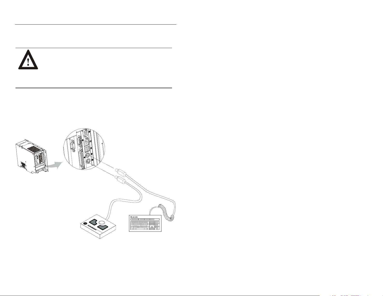
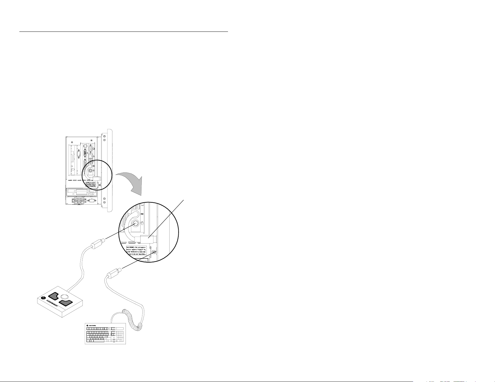
Connecting a Mouse & Keyboard (12.1 in. keypad version)
The 12.1 in. front keypad is jumpered to the CPU board keyboard port. An
external keyboard can be connected and used as shown below. When
connected as shown below, both the front keypad and the external
keyboard can be used simultaneously. Make sure this does not cause any
unsafe operating conditions.
6189-PS2JUMPER cable
required to connect bezel
keypad to the CPU board.
Publication 6181-IN002C-MU-P
Page 21
6181 Industrial Computer 21
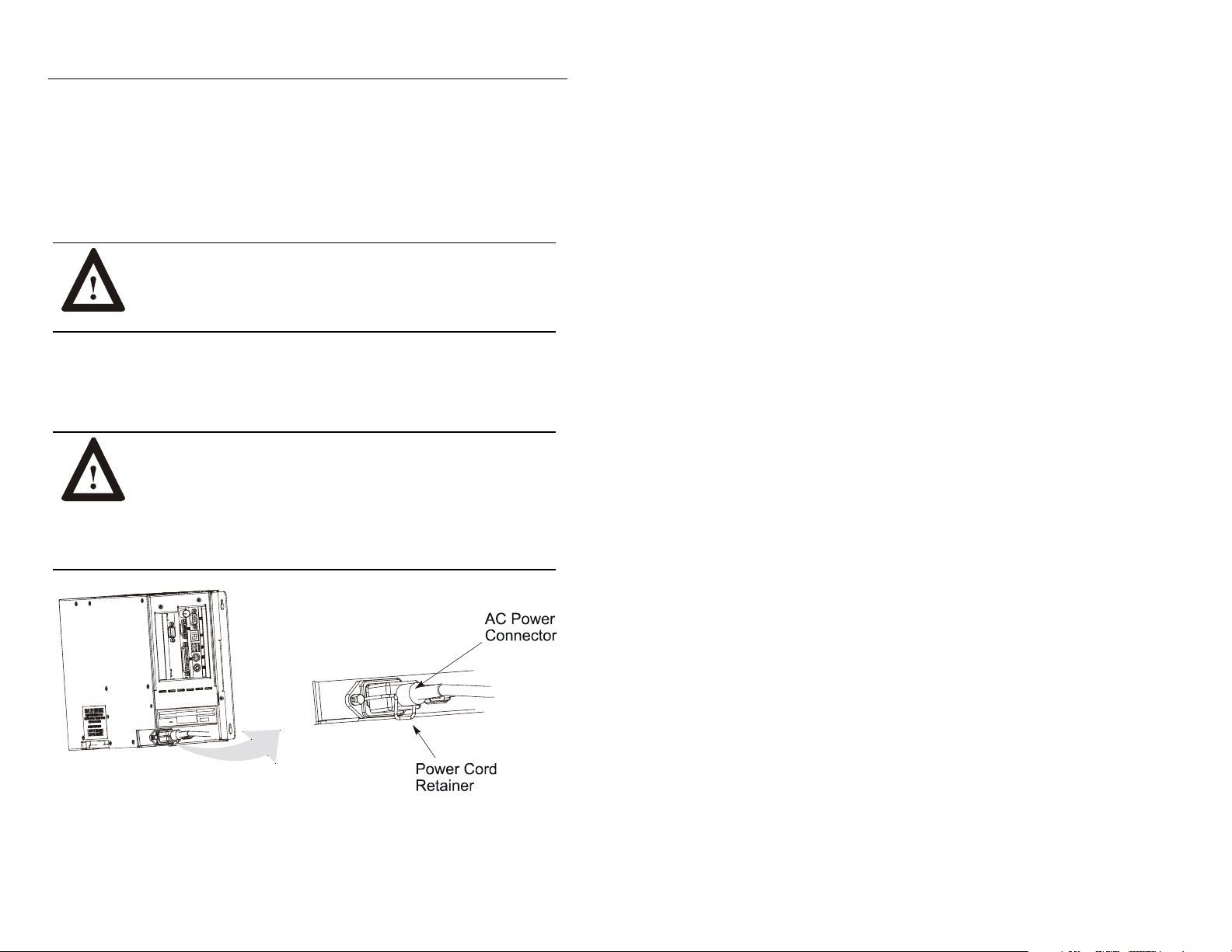
AC Power Connections
A standard IEC 320 power cord provides power to the 6181 Computer AC
version. The power supply input will accept 120/240 V AC. The power
supply is autoswitching.
ATTENTION: The power cord must be connected to an
outlet having an earth ground (three-prong outlet). Failure
to follow this warning could result in severe electrical
shock.
Use the power cord retainer to prevent accidental interruption of power to
the 6181 Computer. Pull the cord retainer over the cord plug as shown
below.
ATTENTION: EXPLOSION HAZARD! You must
install the power cord retainer clip to ensure safety in
hazardous locations.
Failure to secure the power cord with the retainer clip
could result in hazardous conditions if the power cord is
accidentally disconnected.
Publication 6181-IN002C-MU-P
Page 22
22 6181 Industrial Computer
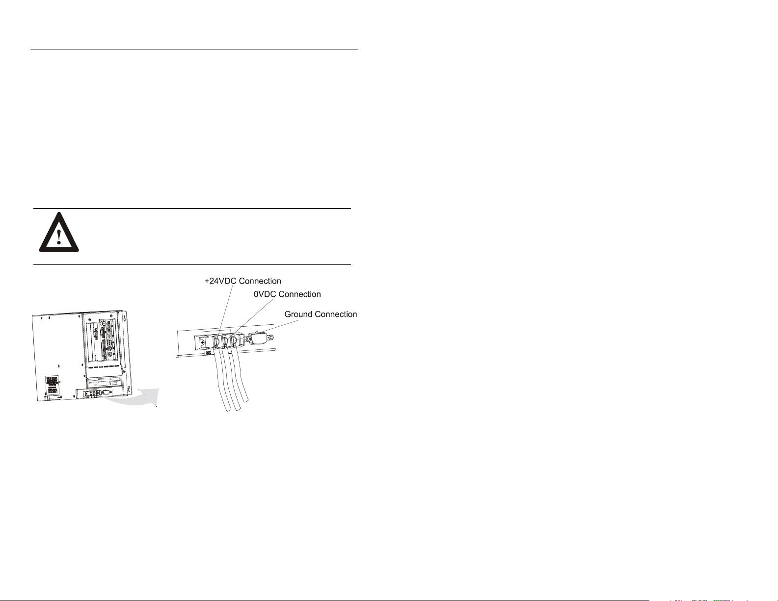
DC Power Connections
A standard three position terminal block is provided for connecting power.
Use 12 or 14 AWG stranded wire to connect these terminals to a stable
source of 24 V DC power with 10 A minimum rating available. Observe
proper polarity and keep the wiring as short as possible (recommend less
than 3 meters). Ensure that the wires are connected correctly using
standard wiring practices.
ATTENTION: The ground connection must be made to
an adequate earth ground using as short a wire as possible
to eliminate the possibility of radio frequency noise and
interference.
Publication 6181-IN002C-MU-P
Page 23

6181 Industrial Computer 23
Network Connections
The 6181 Computer accommodates CAT5 twisted pair Ethernet cabling
with RJ45 connectors to support 100 Mbps network data transfer.
Important:
Performance degradation of your Ethernet communications
is likely to result if the unit or cables are subjected to
extreme radiated or conducted high-frequency noise. It is
the user’s responsibility to properly route cable and
condition input power in order to improve communication
reliability.
Proper cable routing and power conditioning is required
to ensure reliable Ethernet communications in industrial
environments. Rockwell Automation recommends that
all Ethernet cabling be routed through dedicated metal
conduits. Installing ferrite bead filters at cable ends
may also improve reliability.
Replacing the Battery
The 6181 Computer contains a battery to maintain the CMOS settings and
real-time clock. The battery is located in a battery holder on the 6181
Computer backplane. Replace this battery as needed with a Panasonic
battery, part number CR2032, or Allen-Bradley part 6189-1BATT.
ATTENTION: There is a danger of explosion if the
battery is incorrectly replaced. Replace only with the
same or equivalent type recommended by the
manufacturer. Dispose of used batteries according to the
manufacturer's instructions.
Publication 6181-IN002C-MU-P
Page 24

Notice d’installation
Ordinateur industriel 6181
Ordinateur industriel 6181
Ordinateur industriel 6181Ordinateur industriel 6181
Objet du chapitre
Ce chapitre décrit l'installation de l'6181 Industrial Computer, ainsi que la
fixation de l'6181 Computer sur un panneau à l'aide de goujons de
montage ou de brides.
Conformité aux directives de l'Union européenne
Lorsqu'il porte le marquage CE, l'6181 Computer est conforme aux
directives de l'Union européenne et peut être installé dans les pays de
l'Union européenne et de l'Espace Economique Européen. Une copie de la
Déclaration de conformité peut être consultée sur le site internet de
Rockwell Automation/Allen-Bradley : www.ab.com
ATTENTION : L'6181 Computer est conçu pour être
utilisé dans des environnements industriels, ou dans une
salle de commande, dans lesquels l'alimentation est isolée
des sources basse tension du secteur. Certaines
installations peuvent ne pas être conformes à la norme
EN 61000-3-2 – Rayonnement harmonique, telle que
spécifiée par la directive CEM de l'Union européenne.
Vous devez obtenir une autorisation de l'autorité locale
responsable de l'électricité avant de connecter toute
configuration qui consomme plus de 75 Watts c.a.
directement à partir du secteur.
Page 25

Ordinateur industriel 6181 25
Conditions environnementales
Montez l'6181 Computer sur un panneau ou dans une armoire pour
protéger les circuits internes. Les versions avec un boîtier étanche sont
conformes aux normes NEMA Type 1, 12, 13 et 4 (utilisation intérieure) et
CEI IP54, IP65 uniquement lorsqu'elles sont montées sur un panneau ou
dans une armoire qui ont une classification équivalente. La version sans
afficheur ne possède pas de joint et est conforme aux normes NEMA Type
1 et CEI IP2X.
Laissez suffisamment d'espace dans l'armoire pour permettre une
ventilation correcte. Prenez en compte la chaleur dégagée par les autres
équipements présents dans l'armoire. La température ambiante autour de
l'6181 Computer doit être maintenue entre 5 ° et 50 °C (41 ° à 122 °F).
L'6181 Computer est destiné à une utilisation en environnement de
pollution de degré 2.
Assurez-vous de laisser suffisamment d'espace à l'arrière et sur les côtés de
l'6181 Computer pour l'installation et le retrait de composants et pour
l'accès au lecteur de disquettes.
ATTENTION : L'6181 Industrial Computer est conçu
pour être monté verticalement sur un panneau. Ne montez
pas l'6181 Computer avec l'option lecteur de DVD ou
graveur de CD-ROM à plus de 5 degrés de la verticale.
Ceci peut entraîner un mauvais fonctionnement du lecteur
de DVD ou du graveur de CD-ROM et peut endommager
votre disque.
Publication 6181-IN002C-MU-P
Page 26
26 Ordinateur industriel 6181
Matériel de montage
L'6181 Computer est livré avec le matériel de montage suivant :
Tableau B
Matériel de montage
Pièce Description Quantité Utilisation
Ecrou
auto-bloquant
(nº 10-32)
Bride de fixation 6 Montage sur panneau ou
10
(8 requis)
Montage sur panneau ou
en armoire
en armoire
Outils requis
En plus des outils nécessaires pour effectuer la découpe, vous aurez besoin
des outils suivants :
Pour les goujons de montage :
Douille de 0,95 mm (3/8 in)
Tige de 15 cm (6 in) minimum
Clé à douille (clé dynamométrique recommandée)
Règle
Pour les brides de fixation :
Tournevis plat
Règle
Publication 6181-IN002C-MU-P
Page 27
Ordinateur industriel 6181 27
r
Espace de dégagement
Laissez suffisamment d'espace pour permettre le montage, la ventilation et
la maintenance. La figure ci-dessous indique les distances de dégagement
minimum recommandées pour les autres composants sur le rack ou dans
l'armoire.
ATTENTION : L'6181 Computer ne doit pas être utilisé
dans un espace clos, aux dimensions indiquées ci-dessous,
sans une ventilation correcte ou une autre méthode de
refroidissement pour abaisser la température de l'air dans
l'armoire.
Espace supérieur de
50 mm (2 in) pour la ventilation
L’espacement arrière peut être nul.
Espace inférieur de
50 mm (2 in) pour la ventilation
Espace à gaucche de 102 mm (4 in) pou
la ventilation, l’accès au lecteur de
disquette et les connexions des câbles
Espace à droite suffisant pour permettre
l’accès lors du montage
Publication 6181-IN002C-MU-P
Page 28
28 Ordinateur industriel 6181
Dimensions de montage
Les figures suivantes indiquent les dimensions de montage de
l'ordinateur 6181.
Version 10,4 pouces avec afficheur
295,0 [11,61]
Vue frontale
260,4 [10,25]
323,9 [12,75]
Version à 2 emplacements Version à 4 emplacements
139,7 [5,49]
Vue latérale
231,8 [9,125]
Publication 6181-IN002C-MU-P
231.55 [9.116]
231,55 [9,116]
181,71 [7,154]
181.71 [7.154]
Page 29
Ordinateur industriel 6181 29
Version 12,1 pouces avec afficheur
Vue frontale
279,4 [11,00]
295,4 [11,61]
349,25 [13,75]
Version à 2 empl. (vue latérale) Version à 4 empl. (vue latérale)
Vue latérale
147,6 [5,81]
189,64 [7,466]
189.64 [7.466]
231,8 [9,125]
231,55 [9,116]
231.55 [9.116]
Publication 6181-IN002C-MU-P
Page 30
30 Ordinateur industriel 6181
Version 12,1 pouces avec clavier et afficheur
294,82 [11,607]
282,55 [11,124]
415,65 [16,364]
Version à 2 empl. (vue latérale) Version à 4 empl.
143,34 [5,643]
254,76 [10,030]
Publication 6181-IN002C-MU-P
Hauteur : 254,76
Profondeur : 173,02
Page 31

Version sans afficheur
Ordinateur industriel 6181 31
Vue frontale
Version à 2 emplacements Version à 4
emplacements
Vue latérale
231,7
[9,125]
190,5
[7,50]
295,0 [11,62]
317,5 [12,50]
342,9 [13,50]
123,7 [4,87]
Hauteur : 231,7
Profondeur : 153,44
231,7 [9,125]
Publication 6181-IN002C-MU-P
Page 32

32 Ordinateur industriel 6181
Dimensions de montage – avec l'option baie d'extension
Les figures suivantes indiquent les dimensions de montage de l'ordinateur
6181 avec l'option de baie d'extension installée. L'option de baie
d'extension est valide pour toutes les options d'armoire 6181.
Vue frontale
Vue latérale
24,5
[0,97]
15,8 [0,62]
164,9 [6,49]
45,2
[1,78]
266,7
[10,50]
45,2
[1,78]
66,7 [2,63]
Publication 6181-IN002C-MU-P
Page 33

Ordinateur industriel 6181 33
Découpe de montage pour le 10,4 pouces
La figure suivante indique les dimensions de découpe pour le montage sur
panneau ou dans une armoire de l'ordinateur 6181 version de 10,4 pouces.
Publication 6181-IN002C-MU-P
Page 34

34 Ordinateur industriel 6181
Découpe de montage pour le 12,1 pouces
La figure suivante indique les dimensions de découpe pour le montage sur
panneau ou dans une armoire de l'ordinateur 6181 version de 12,1 pouces.
Publication 6181-IN002C-MU-P
Page 35

Ordinateur industriel 6181 35
Découpe de montage pour le 12,1 pouces avec clavier
La figure suivante indique les dimensions de découpe pour le montage sur
panneau ou dans une armoire de l'ordinateur 6181 version de 12,1 pouces
avec clavier.
389,89 [15,35]
256,8 [10,11]
Publication 6181-IN002C-MU-P
Page 36

36 Ordinateur industriel 6181
Montage sur panneau avec goujons de montage
Pour installer l'ordinateur 6181 sur un panneau à l'aide de 8 goujons de
montage :
ATTENTION : Déconnectez toute alimentation
électrique du panneau avant d'effectuer la découpe.
Assurez-vous que la zone autour de la zone de découpe
est dégagée.
Prenez les précautions nécessaires pour éviter que des
copeaux de métal n'entrent dans les composants déjà
installés sur le panneau.
Le non respect de ces directives peut entraîner des
blessures ou endommager les composants du panneau.
7. Découpez une ouverture dans le panneau en respectant les dimensions
de découpe indiquées page 33 ou 34. Percez huit trous de 6,4 mm
(0,25 in) pour les goujons de montage, tel qu'indiqué.
8. Vérifiez que le joint d'étanchéité est correctement positionné sur le
terminal. Ce joint constitue un joint d'étanchéité par compression
(NEMA Type 4). N'utilisez pas d'enduit d'étanchéité.
9. Positionnez l'6181 Computer dans la découpe du panneau en alignant
les goujons avec les trous de montage.
10. Installez les 8 écrous auto-bloquants et serrez à la main.
Publication 6181-IN002C-MU-P
Page 37

Ordinateur industriel 6181 37
11. Serrez les écrous auto-bloquants en alternance (utilisez une clé de
0,95 mm – 3/8 in) jusqu'à ce que l'6181 Computer soit fermement
maintenu sur le panneau (voir la séquence de serrage recommandée cidessous). Le couple de vissage requis augmente de façon significative
lorsque le joint approche de la compression correcte. Serrez les écrous
avec un couple de 2,7 N-m (24 in-lb).
Ordre de serrage
recommandée
La séquence de serrage commence par
les goujons du centre et continue
goujons des coins.
ATTENTION : Serrez les écrous avec un couple de
2,7 N-m (24 in-lb) pour obtenir un joint d'étanchéité
correct et pour éviter tout endommagement de l'6181
Computer. Rockwell Automation ne peut être tenu pour
responsable de tout endommagement du terminal, ou de
tout autre équipement présent dans l'armoire, causé par
une infiltration d'eau ou de produits chimiques résultant
d'une mauvaise installation.
avec les
Publication 6181-IN002C-MU-P
Page 38

38 Ordinateur industriel 6181
Montage sur panneau avec brides de fixation
Pour installer l'6181 Computer sur un panneau à l'aide de brides de
fixation :
ATTENTION : Déconnectez toute alimentation
électrique du panneau avant d'effectuer la découpe.
Assurez-vous que la zone autour de la zone de découpe
est dégagée.
Prenez les précautions nécessaires pour éviter que des
copeaux de métal n'entrent dans les composants déjà
installés sur le panneau.
Le non-respect de ces directives peut entraîner des
blessures ou endommager les composants du panneau.
1. Découpez une ouverture dans le panneau en respectant les dimensions
de découpe indiquées page 35.
2. Vérifiez que le joint d'étanchéité de l'6181 Computer est correctement
positionné sur le terminal. Ce joint constitue un joint d'étanchéité par
compression. N'utilisez pas d'enduit d'étanchéité.
3. Positionnez l'6181 Computer dans la découpe du panneau.
Publication 6181-IN002C-MU-P
Page 39

Ordinateur industriel 6181 39
4. Installez les brides de fixation. Les brides se glissent dans les ergots
situés en haut et en bas de l'6181 Computer.
Ordre de serrage
recommandé
Bride
de fixation
5. Serrez graduellement les brides autour du boîtier en respectant la
séquence de serrage spécifiée. Répétez cette procédure au moins trois
fois, jusqu'à ce que vous ayez bien serré les brides à la main et que le
joint soit comprimé de façon uniforme contre le panneau.
6. Serrez les brides avec un couple de 1,1 N-m (10 in-lb) en respectant la
séquence indiquée ci-dessus. Ne serrez pas trop.
Publication 6181-IN002C-MU-P
Page 40

40 Ordinateur industriel 6181
ATTENTION : Serrez les brides de fixation avec un couple
de 1,1 N-m (10 in-lb) pour obtenir un joint d'étanchéité
correct et pour éviter tout endommagement de l'6181
Computer. Rockwell Automation ne peut être tenu pour
responsable de tout endommagement du terminal, ou de tout
autre équipement présent dans l'armoire, causé par une
infiltration d'eau ou de produits chimiques résultant d'une
mauvaise installation.
Connexion d'équipement en environnement dangereux
Certaines configurations spécifiques de l'ordinateur 6181 sont certifiées
pour une utilisation de Classe I, division 2, groupes A, B, C, D, code de
température T4A, environnements dangereux. Lorsque vous installez cet
équipement dans un environnement dangereux, observez les
recommandations de sécurité suivantes :
Câblage de l'installation
Voir la plaque d'identification sur l'ordinateur pour connaître la
certification pour les environnements dangereux.
ATTENTION : Dans les environnements dangereux de
Classe I, Div 2, l'6181 Industrial Computer doit être câblé
en conformité avec le code électrique américain
« National Electric Code » et/ou le code canadien
« Canadian Electric Code » en fonction de l'environnement
dangereux.
Connexion et déconnexion de l'équipement
Lorsque vous installez l'ordinateur 6181, respectez les considérations de
sécurité suivantes :
ATTENTION : DANGER D'EXPLOSION ! Ne connectez
et ne déconnectez pas les équipements si le circuit est sous
tension, à moins que l'environnement soit classé non
dangereux.
Note :
N'effectuez aucune connexion ou déconnexion si des
matériaux potentiellement dangereux sont présents. Une
connexion ou une déconnexion peut provoquer une étincelle.
Publication 6181-IN002C-MU-P
Page 41

Ordinateur industriel 6181 41
Périphériques
ATTENTION : Les équipements périphériques
connectés à l'6181 Computer ne doivent pas être mis en
marche si des matériaux dangereux sont présents, à moins
que ces équipements spécifiques ne soient conformes aux
environnements dangereux de Classe I, Div 2. Ces
équipements peuvent être des claviers externes, des souris
externes et des lecteurs de support externes.
Connexion d'une souris et d'un clavier (panneau latéral)
La souris et le clavier se connectent sur les ports souris et clavier du
panneau latéral, tel qu'illustré ci-dessous.
Publication 6181-IN002C-MU-P
Page 42

42 Ordinateur industriel 6181
Connexion d'une souris et d'un clavier (version 12,1 pouces avec clavier)
Le clavier de la face avant du modèle 12,1 pouces possède un cavalier relié
au port clavier de la carte de l'UC. Un clavier externe peut être connecté,
comme illustré ci-dessous. Avec un clavier connecté comme le montre
l'illustration ci-dessous, les deux claviers (intégré et externe) peuvent être
utilisés simultanément. Assurez-vous que cette utilisation ne crée pas de
fonctionnement non sécurisé.
Câble 6189-PS2JUMPER requis
pour connecter le clavier du
boîtier à la carte de l’UC.
Publication 6181-IN002C-MU-P
Page 43

Ordinateur industriel 6181 43
Connexions de l'alimentation c.a.
Un cordon d'alimentation standard CEI 320 fournit l'alimentation à l'6181
Computer version c.a. L'entrée d'alimentation accepte des tensions de
120/240 V c.a. L'alimentation est commutée automatiquement.
ATTENTION : Le cordon d'alimentation doit être
connecté à une prise avec mise à la terre (prise à trois
broches). Le non-respect de cette précaution peut
entraîner un choc électrique.
Utilisez la retenue de câble pour empêcher une interruption accidentelle de
l'alimentation de l'6181 Computer. Placez la retenue du câble sur le
connecteur du cordon, tel qu'illustré ci-dessous.
ATTENTION : DANGER D'EXPLOSION ! Vous devez
installer la bride de retenue du câble d'alimentation pour
assurer une sécurité en environnement dangereux.
Si le cordon d'alimentation n'est pas bloqué par la bride de
retenue, cela peut créer des conditions dangereuses si le
cordon se trouve accidentellement déconnecté.
Connecteur
d’alimentation
Retenue du cordon
d’alimentation
Publication 6181-IN002C-MU-P
c.a.
Page 44

44 Ordinateur industriel 6181
Connexions de l'alimentation c.c.
Un bornier standard à trois positions est fourni pour la connexion de
l'alimentation. Utilisez des câbles torsadés de calibre 12 ou 14 pour la
connexion des bornes à une source d'alimentation 24 V c.c. stable avec une
capacité nominale de 10 A minimum. Respectez la polarité correcte et
utilisez des fils aussi court que possible (moins de 3 mètres recommandé).
Vérifiez que les fils sont correctement connectés, en respectant les
pratiques de câblage standard.
ATTENTION : La connexion de mise à la terre doit être
effectuée sur une mise à la terre correcte en utilisant un fil
aussi court que possible pour éliminer les risques de
parasites et d'interférences radio.
Connexion +24 V c.c.
Connexion 0 V c.c.
Connexion de mise
à la terre
Publication 6181-IN002C-MU-P
Page 45

Ordinateur industriel 6181 45
Connexions du réseau
L'6181 Computer accepte des câbles Ethernet à paire torsadée CAT5 avec
connexions RJ45 pour le transfert des données à 100 Mbps sur le réseau.
Important :
Une dégradation des communications Ethernet est à
attendre si l'équipement ou les câbles sont soumis à des
parasites haute fréquence par rayonnement ou
conductivité. C'est la responsabilité de l'utilisateur de
s'assurer de l'acheminement correct des câbles et du bon
conditionnement de l'alimentation pour améliorer la
fiabilité des communications.
Un acheminement correct des câbles et un bon
conditionnement de l'alimentation sont requis pour
assurer la fiabilité des communications Ethernet en
environnement industriel. Rockwell Automation
recommande d'acheminer tous les câbles Ethernet par
des conduits dédiés en métal. L'installation de filtres à
anneau de ferrite aux extrémités des câbles peut
également améliorer la fiabilité.
Remplacement de la pile
La station 6181 contient une pile pour préserver les réglages CMOS et de
l’horloge temps réel. La pile est située dans un compartiment sur le fond
de panier de la 6181. Remplacez la pile au besoin avec une pile Panasonic,
référence CR2032, ou Allen-Bradley, référence 6189-1BATT.
ATTENTION : Il existe un risque d’explosion si la pile
est remplacée par une pile non adaptée. Ne remplacez la
pile que par une pile identique ou équivalente
recommandée par le fabricant. Respectez les instructions
du fabricant pour la mise au rebus des piles.
Publication 6181-IN002C-MU-P
Page 46

Installationsanleitung
Industriecomputer 6181
Industriecomputer 6181
Industriecomputer 6181Industriecomputer 6181
Inhalt
Dieses Kapitel beschreibt den Einbau der 6181 Industrial Computer,
einschließlich des Einbaus der6181 Computer 6181 in einen Schaltschrank
mit Hilfe von Befestigungsschrauben oder Klammern.
Übereinstimmung mit den Richtlinien der Europäischen Union
Der 6181 Computer erfüllt die Anforderungen der EU-Richtlinien, wenn er
innerhalb der Europäischen Union oder in EWR-Regionen installiert wird
und das CE-Zeichen trägt. Eine Kopie der Konformitätserklärung
(Declaration of Conformity) steht auf der Internet-Site von Rockwell
Automation/Allen-Bradley zur Verfügung: www.ab.com
ACHTUNG: Der Computer wurde für den Betrieb in
einer industriellen Produktionsumgebung entwickelt, wo
bereits eine gewisse Art der Leistungsisolierung vom
öffentlichen Spannungsnetz verwendet wird. Einige
Konfigurationen entsprechen eventuell nicht dem
Standard EN 61000-3-2 zu Oberschwingungsströmen, wie
durch die EMV-Richtlinie der Europäischen Union
festgelegt. Daher müssen Sie vor dem Anschließen einer
beliebigen Konfiguration mit einer Leistungsaufnahme
von über 75 Watt AC-Leistung direkt über das öffentliche
Stromnetz zunächst die Erlaubnis des lokalen
Stromversorgers einholen.
Page 47

Industriecomputer 6181 47
Hinweise zu den Umgebungsbedingungen
Montieren Sie den 6181 Computer in einem Schaltschrank oder Gehäuse,
um die internen Schaltkreise zu schützen. Ausführungen mit einer
Dichtungsblende erfüllen die NEMA-Standards vom Typ 1, 12, 13 und 4
(Innenraumverwendung) sowie die IEC-Standards IP54 und IP65 nur,
wenn sie in einem Schaltschrank oder einem Gehäuse mit der gleichen
Schutzart montiert werden. Die Ausführung ohne Anzeige ist nicht mit
einer Dichtung ausgestattet und entspricht dem NEMA-Standard vom Typ
1 und dem IEC-Standard IP2X.
Achten Sie auf ausreichend Platz innerhalb des Gehäuses, um eine
ausreichende Belüftung zu gewährleisten. Berücksichtigen Sie darüber
hinaus auch die Wärme, die von anderen Geräten im Gehäuse erzeugt
wird. Die Umgebungstemperatur für den 6181 Computer muss zwischen
5 °C und 50 °C liegen. Der 6181 Computer ist für den Einsatz in
Umgebungen mit Verschmutzungsgrad 2 geeignet.
Vergewissern Sie sich, dass der 6181 Computer von hinten und von der
Seite zugänglich ist, um Komponenten ein- und ausbauen sowie auf das
Diskettenlaufwerk zugreifen zu können.
ACHTUNG: Der 6181 Industrial Computer wurde für
die vertikale Montage in einem Schaltschrank entwickelt.
Montieren Sie den 6181 Computer mit DVD-ROM- oder
CD-R/W-Option nicht in einem Winkel, der mehr als
5 Grad von der Vertikalen abweicht. Dies kann zu
Betriebsfehlern des DVD-ROM- oder CD-R/WLaufwerks und zur Beschädigung Ihrer Datenträger
führen.
Publikation 6181-IN002C-MU-P
Page 48

48 Industriecomputer 6181
Montagezubehör
Der 6181 Computer wird mit folgendem Montagezubehör geliefert:
Tabelle C
Montagezubehör
Komponente Beschreibung Menge Verwendungszweck
Selbstsichernde
Muttern
(Nr. 10-32)
Montageklammern 6 Schaltschrank- oder
10
(8 erforderlich)
Schaltschrank- oder
Gehäusemontage
Gehäusemontage
Erforderliche Werkzeuge
Neben den für den Ausschnitt erforderlichen Werkzeugen benötigen Sie
auch folgende Werkzeuge:
Für Befestigungsschrauben:
3/8-Zoll-Steckschlüsseleinsatz
Steckschlüsselverlängerung (mind. 15 cm)
Steckschlüssel (Nm-Drehmoment-Schraubenschlüssel empfohlen)
Lineal
Für Montageklammern:
Schlitzschraubendreher
Lineal
Publikation 6181-IN002C-MU-P
Page 49

Industriecomputer 6181 49
A
A
A
A
Montagefreiräume
Lassen Sie ausreichend Platz für die Montage, Belüftung und Wartung.
Die nachfolgende Abbildung veranschaulicht die empfohlenen
Mindestabstände zu anderen Komponenten im Rack oder Gehäuse.
ACHTUNG: Der 6181 Computer darf nicht in Gehäusen
betrieben werden, welche die nachfolgenden Maße
unterschreiten, es sei denn, es wird für eine ausreichende
Belüftung oder andere Kühlmethoden zur Senkung der
Lufttemperatur innerhalb des Gehäuses gesorgt.
bstand nach oben
50 mm für Belüftung
bstand zur Rückseite kann Null sein
102 mm links für Belüftung,
Zugriff auf Diskettenlaufwerk
bstand nach unten
50 mm für Belüftung
bstand nach rechts
ausreichend für
Montage
und Kabelanschlüsse
Publikation 6181-IN002C-MU-P
Page 50

50 Industriecomputer 6181
Einbaumaße
Die folgenden Abbildungen zeigen die Einbaumaße für den Computer
6181.
10,4-Zoll-Ausführung mit Anzeige
295,0
Vorderansicht
260,4
323,9
Ausführung Ausführung mit 2 Steckplätzen mit 4 Steckplätzen
139,7
Seitenansicht
231,8
Publikation 6181-IN002C-MU-P
231,55
231.55 [9.116]
181,71
181.71 [7.154]
Page 51

Industriecomputer 6181 51
12,1-Zoll-Ausführung mit Anzeige
Ausführung Ausführung mit 2 Steckplätzen mit 4 Steckplätzen (Seitenansicht) (Seitenansicht)
Seitenansicht
Vorderansicht
279,4
147,6
349,25
295,0
189,64
189.64 [7.466]
231,8
231,55
231.55 [9.116]
Publikation 6181-IN002C-MU-P
Page 52

52 Industriecomputer 6181
12,1-Zoll-Ausführung mit Tastatur und Anzeige
294,82
282,55
415,65
Ausführung mit Ausführung mit 2 Steckplätzen (Seitenansicht) 4 Steckplätzen
143,34
254,76
Publikation 6181-IN002C-MU-P
Höhe: 254,76
Tiefe: 173,02
Page 53

Ausführung ohne Anzeige
Industriecomputer 6181 53
Seitenansicht
Vorderansicht
231,7
295,0
190,5
317,5
342,9
Ausführung mit Ausführung mit 2 Steckplätzen 4 Steckplätzen
123,7
Höhe: 231,7
Tiefe: 153,44
231,7
Publikation 6181-IN002C-MU-P
Page 54

54 Industriecomputer 6181
A
Einbaumaße – mit optionalem Erweiterungsrahmen
Die folgenden Abbildungen zeigen die Einbaumaße für den
Computer 6181 mit installiertem Erweiterungsrahmen. Der optionale
Erweiterungsrahmen ist für alle 6181-Gehäuse geeignet.
nsicht von oben
Seitenansicht
24,5
15,8
164,9
266,7
45,2
45,2
66,7
Publikation 6181-IN002C-MU-P
Page 55

Industriecomputer 6181 55
10,4-Zoll-Einbauausschnitt
In der folgenden Abbildung werden die Abmessungen für den Ausschnitt
im Schaltschrank oder dem Gehäuse für die 10,4-Zoll-Ausführung des
Computers 6181 dargestellt.
247,7
123,8
311,2
155,6
6,4
298,5
8 x 6,4 DURCHMESSER
6,4
235,0
Publikation 6181-IN002C-MU-P
Page 56

56 Industriecomputer 6181
R
12,1-Zoll-Einbauausschnitt
In der folgenden Abbildung werden die Abmessungen für den Ausschnitt
im Schaltschrank oder dem Gehäuse für die 12,1-Zoll-Ausführung des
Computers 6181 dargestellt.
266,7
133,4
336,6
168,3
6,4
323,9
323,9
8 x 6,4 DURCHMESSE
6,4
254,0
Publikation 6181-IN002C-MU-P
Page 57

Industriecomputer 6181 57
12,1-Zoll-Einbauausschnitt für Tastatur
In der folgenden Abbildung werden die Abmessungen für den Ausschnitt
im Schaltschrank oder dem Gehäuse für die 12,1-Zoll-Ausführung des
Computers 6181 mit Tastatur dargestellt.
389,89
256,8
Publikation 6181-IN002C-MU-P
Page 58

58 Industriecomputer 6181
Schaltschrankmontage mit Befestigungsschrauben
So installieren Sie den Computer 6181 mit 8 Befestigungsschrauben in
einem Schaltschrank:
ACHTUNG: Unterbrechen Sie sämtliche
Stromverbindungen zum Schaltschrank, bevor Sie mit
dem Ausschnitt beginnen.
Stellen Sie sicher, dass der Bereich um den
Schaltschrankausschnitt frei ist.
Treffen Sie Vorsichtsmaßnahmen, damit keine
Metallspäne in die bereits im Schaltschrank installierten
Komponenten eindringen.
Die Missachtung dieser Warnhinweise kann zu
Verletzungen von Personen oder Beschädigungen der
Schaltschrankkomponenten führen.
7. Schneiden Sie gemäß der jeweiligen auf den Seiten 55 oder 56
angegebenen Ausschnittmaße eine Öffnung in den Schaltschrank.
Bohren Sie den Angaben entsprechend vorsichtig acht 6,4 mm große
Löcher für die Befestigungsschrauben.
8. Stellen Sie sicher, dass die Dichtung ordnungsgemäß am Gerät
angebracht ist. Die Dichtwirkung ergibt sich durch das
Zusammendrücken der Dichtung (NEMA Typ 4). Verwenden Sie
keine zusätzlichen Dichtungsmittel.
9. Ordnen Sie den 6181 Computer so im Schaltschrankausschnitt an, dass
sich die Schrauben über den Befestigungslöchern befinden.
10. Ziehen Sie die acht selbstsichernden Muttern handfest.
Publikation 6181-IN002C-MU-P
Page 59

Industriecomputer 6181 59
11. Ziehen Sie die selbstsichernden Muttern abwechselnd fest (verwenden
Sie einen 3/8-Zoll-Steckschlüsseleinsatz), bis der 6181 Computer fest
im Schaltschrank sitzt (empfohlene Schraubreihenfolge siehe unten).
Das Anzugsdrehmoment steigt erheblich an, wenn die Dichtung den
richtigen Anpressdruck erreicht. Ziehen Sie die Muttern mit einem
Drehmoment von 2,7 Nm fest.
8
Empfohlene
Schraubreihenfolge
3
6
Mit den mittleren Schrauben beginnen und
anschließend die Eckschrauben festziehen.
ACHTUNG: Ziehen Sie die Muttern mit einem
Drehmoment von 2,7 Nm fest, damit eine
ordnungsgemäße Abdichtung gegeben ist und Schäden
am 6181 Computer vermieden werden. Rockwell
Automation übernimmt bei unsachgemäßer Installation
keine Haftung für Schäden durch Wasser oder
Chemikalien am Computer oder an anderen Geräten
innerhalb des Gehäuses.
Publikation 6181-IN002C-MU-P
Page 60

60 Industriecomputer 6181
Schaltschrankmontage mit Montageklammern
So installieren Sie den 6181 Computer mit Montageklammern in einem
Schaltschrank:
ACHTUNG: Unterbrechen Sie sämtliche
Stromverbindungen zum Schaltschrank, bevor Sie mit
dem Ausschnitt beginnen.
Stellen Sie sicher, dass der Bereich um den
Schaltschankausschnitt frei ist.
Treffen Sie Vorsichtsmaßnahmen, damit keine
Metallspäne in die bereits im Schaltschrank installierten
Komponenten eindringen.
Die Missachtung dieser Warnhinweise kann zu
Verletzungen von Personen oder Beschädigungen der
Schaltschrankkomponenten führen.
12. Schneiden Sie gemäß der auf Seite 57 angegebenen Ausschnittmaße
eine Öffnung in den Schaltschrank.
13. Stellen Sie sicher, dass die Dichtung des 6181 Computer
ordnungsgemäß am Gerät angebracht ist. Die Dichtwirkung ergibt sich
durch das Zusammendrücken der Dichtung. Verwenden Sie keine
zusätzlichen Dichtungsmittel.
14. Ordnen Sie den 6181 Computer im Schaltschrankausschnitt an.
Publikation 6181-IN002C-MU-P
Page 61

Industriecomputer 6181 61
15. Installieren Sie die Montageklammern. Die Klammern lassen sich in
die Schlitze an der Ober- und Unterseite des 6181 Computer
einschieben.
Empfohlene
Schraubreihen-
folge
Montage-
klammer
16. Ziehen Sie die Klammern nacheinander und in der angegebenen
Reihenfolge rund um die Blende fest. Wiederholen Sie diesen Vorgang
mindestens dreimal, bis die Klammern handfest angezogen sind und
die Dichtung gleichmäßig gegen den Schaltschrank gedrückt wird.
17. Ziehen Sie die Montageklammern in der oben beschriebenen
Reihenfolge mit einem Drehmoment von 1,1 Nm fest. Ziehen Sie die
Klammern nicht zu fest.
Publikation 6181-IN002C-MU-P
Page 62

62 Industriecomputer 6181
ACHTUNG: Ziehen Sie die Klammern mit einem
Drehmoment von 1,1 Nm fest, damit eine ordnungsgemäße
Abdichtung gegeben ist und Schäden am 6181 Computer
vermieden werden. Rockwell Automation übernimmt bei
unsachgemäßer Installation keine Haftung für Schäden
durch Wasser oder Chemikalien am Computer oder an
anderen Geräten innerhalb des Gehäuses.
Anschließen der Ausrüstung in Gefahrenbereichen
Spezielle Konfigurationen des 6181 Computer sind für Gefahrenbereiche
der Klasse I, Division 2, Gruppen A, B, C, D, Temperaturcode T4A
zertifiziert. Beachten Sie bei der Installation des 6181 Computer in einem
Gefahrenbereich die folgenden Sicherheitsvorkehrungen:
Installationsverdrahtung
Zertifizierungen für Gefahrenbereiche entnehmen Sie bitte dem
Typenschild am Computer.
ACHTUNG: In Gefahrenbereichen der Klasse I, Div. 2
muss der 6181 Industrial Computer wie in den NECVorschriften (National Electric Code) und/oder dem
Canadian Electric Code für Gefahrenbereiche angegeben
installiert werden.
Anschließen und Trennen von Geräten
Beachten Sie bei der Installation des 6181 folgende
Sicherheitsvorkehrungen:
ACHTUNG: EXPLOSIONSGEFAHR! Geräte dürfen
nur dann bei unter Spannung stehenden Schaltkreisen
angeschlossen oder getrennt werden, wenn es sich um
eine ungefährliche Umgebung handelt.
Hinweis:
Anschlüsse dürfen in Gegenwart möglicherweise
gefährlicher Materialien nicht durchgeführt oder getrennt
werden. Beim Durchführen oder Unterbrechen solcher
Anschlüsse kann es zu Funkenbildung kommen.
Publikation 6181-IN002C-MU-P
Page 63

Industriecomputer 6181 63
Peripheriegeräte
ACHTUNG: Am 6181 Computer angeschlossene
Peripheriegeräte dürfen nicht in Gegenwart
möglicherweise gefährlicher Materialen betrieben werden,
sofern diese Geräte nicht für Umgebungen gemäß Klasse I,
Div. 2 zugelassen sind. Beispiele für solche Geräte sind
externe Tastatur, externe Maus und externe Laufwerke für
Wechseldatenträger.
Anschließen von Maus und Tastatur (Seitenwand)
Maus und Tastatur können wie unten dargestellt an den Schnittstellen für
Maus und Tastatur seitlich am Gerät angeschlossen werden.
Publikation 6181-IN002C-MU-P
Page 64

64 Industriecomputer 6181
Anschließen von Maus und Tastatur (12,1-Zoll-Ausführung)
Die Brücken der 12,1-Zoll Tastatur an der Frontseite sind so konfiguriert,
dass diese am Tastaturanschluss der CPU-Platine angeschlossen werden
kann. Eine externe Tastatur kann wie nachfolgend dargestellt
angeschlossen und verwendet werden. Erfolgt der Anschluss wie unten
gezeigt, lassen sich Fronttastatur und externe Tastatur gleichzeitig
einsetzen. Achten Sie darauf, dass dies hinsichtlich des Betriebs nicht zu
Bedienkonflikten führt.
Zum Anschließen der
Fronttastatur an der
CPU-Platine ist ein
6189-PS2-Brückenkabel
erforderlich.
Publikation 6181-IN002C-MU-P
Page 65

Industriecomputer 6181 65
A
Anschließen der Wechselspannungsversorgung
Die Wechselspannungsausführung (AC) des 6181 Computer wird über ein
Netzkabel gemäß IEC 320 gespeist. Das Netzteil ist für 120/240 V AC
ausgelegt. Es schaltet automatisch zwischen den beiden Spannungswerten
um.
ACHTUNG: Das Netzkabel muss an eine geerdete
Steckdose angeschlossen werden. Bei Missachtung dieser
Warnung besteht Verletzungsgefahr durch Stromschläge.
Verwenden Sie die Netzkabelhalterung, um eine unbeabsichtigte
Spannungsunterbrechung beim 6181 Computer zu verhindern. Ziehen Sie
die Kabelhalterung wie im Folgenden dargestellt über den
Anschlussstecker.
ACHTUNG: EXPLOSIONSGEFAHR! Die Klammer der
Netzkabelhalterung muss installiert werden, um
Sicherheit in Gefahrenbereichen zu gewährleisten.
Ist das Netzkabel nicht mit der Halterungsklammer
gesichert, kann es zu Gefahrensituationen kommen, wenn
das Netzkabel versehentlich abgezogen wird.
C-Netz-
anschluss
Netzkabelhalterung
Publikation 6181-IN002C-MU-P
Page 66

66 Industriecomputer 6181
Anschließen der Gleichspannungsversorgung
Zum Anschließen der Spannungsversorgung steht eine
Standardklemmenleiste mit drei Klemmen zur Verfügung. Verwenden Sie
zum Anschließen dieser Klemmen an eine stabile Spannungsquelle
(24 V DC), die einen Mindestrom von 10 A liefert, verdrillte Leitungen der
Stärke AWG 12 oder AWG 14. Achten Sie auf die richtige Polung und auf
möglichst kurze Verdrahtungswege (empfohlen sind maximal 3 m). Stellen
Sie sicher, dass die Leitungen gemäß den allgemeinen
Verdrahtungstechniken angeschlossen werden.
ACHTUNG: Der Erdanschluss muss an einem
geeigneten Erdleiter und mit einem möglichst kurzen
Leiter vorgenommen werden, um Hochfrequenzstörungen
zu vermeiden.
+24-V-DC-Anschluss
0-V-DC-Anschluss
Erdanschluss
Publikation 6181-IN002C-MU-P
Page 67

Industriecomputer 6181 67
Anschluss an ein Netzwerk
Der 6181 Computer ist mit paarweise verdrillten CAT5-Ethernet-Kabeln
mit RJ45-Steckverbindern ausgestattet, um eine Datenübertragung im
Netzwerk mit 100 MBit/s zu gewährleisten.
Wichtig:
Falls das Gerät oder die Kabel extremen abgestrahlten oder
geleiteten Hochfrequenzstörungen ausgesetzt sind, kann es
zu Leistungsminderungen Ihrer Ethernet-Kommunikation
kommen. Für die ordnungsgemäße Kabelverlegung und die
Aufbereitung der Eingangsspannung zur Verbesserung der
Kommunikationszuverlässigkeit ist der Benutzer
verantwortlich.
Um eine zuverlässige Ethernet-Kommunikation in
Industrieumgebungen zu gewährleisten, ist eine
ordnungsgemäße Verlegung der Kabel sowie die
korrekte Aufbereitung der Spannung erforderlich.
Rockwell Automation empfiehlt, alle Ethernet-Kabel in
speziellen Metallschutzrohren zu verlegen. Die
Installation von Ferritfiltern an den Kabelenden kann
die Zuverlässigkeit ebenfalls erhöhen.
Austausch der Batterie
Der Computer 6181 ist mit einer Batterie ausgestattet, damit die CMOS- und
Echtzeituhr-Einstellungen nicht verloren gehen. Die Batterie befindet sich im
Batteriefach an der Backplane des Computers 6181. Sie können diese Batterie bei
Bedarf durch eine Panasonic-Batterie mit der Teilenummer CR2032 oder eine
Batterie von Allen-Bradley mit der Teilenummer 6189-1BATT ersetzen.
ACHTUNG: Bei unsachgemäßem Austausch der
Batterie besteht Explosionsgefahr. Ersetzen Sie die
Batterie nur durch denselben oder den vom Hersteller
empfohlenen Batterietyp. Entsorgen Sie gebrauchte
Batterien gemäß den Herstellerangaben.
Publikation 6181-IN002C-MU-P
Page 68

Instrucciones de instalación
Ordenador industrial 6181
Ordenador industrial 6181
Ordenador industrial 6181Ordenador industrial 6181
Objetivo del capítulo
Este capítulo describe la instalación del 6181 Industrial Computer incluso
cómo instalar el 6181 Computer en un panel usando pernos o lengüetas de
montaje.
Adherencia a las normas de la Unión Europea
El 6181 Computer cumple con los requisitos de la Directiva de la Unión
Europea cuando se instala dentro de la Unión Europea o regiones de la
EEA y lleva la marca CE. Un ejemplar de la Declaración de Conformidad
está disponible en el sitio web de Rockwell Automation/Allen-Bradley:
www.ab.com
ATENCIÓN: El 6181 Computer ha sido diseñado para
funcionar en un ambiente industrial o sala de control, los
cuales cuentan con un tipo de aislamiento de potencia de
la red pública de alimentación eléctrica con voltaje bajo.
Hay algunas configuraciones que pueden no cumplir con
la norma de Emisiones Armónicas EN 51000-3-2 según
estipuladas por la Directiva de EMC de la Unión Europea.
Consiga permiso de la empresa de alimentación eléctrica
local antes de conectar cualquier configuración que
consuma más de 75 watts de alimentación eléctrica de CA
directamente de la red pública de alimentación eléctrica.
Page 69

Ordenador industrial 6181 69
Consideraciones ambientales
Monte el 6181 Computer en un panel o envolvente para proteger los
circuitos internos. Las versiones que tienen un bisel con empaquetadura
cumplen las normas NEMA de tipo 1, 12, 13 y 4 (uso interior) e IEC IP54,
IP65 solamente cuando se montan en un panel o envolvente con la misma
clasificación. La versión sin pantalla no cuenta con una empaquetadura y
tiene la clasificación de NEMA de tipo 1 e IEC IP2X.
Deje espacio suficiente dentro del envolvente para proporcionar la
ventilación adecuada. Además, tome en cuenta el calor producido por los
otros dispositivos en el envolvente. La temperatura ambiente alrededor del
6181 Computer debe mantenerse entre 5° y 50 °C (41° a 122 °F). El 6181
Computer es para uso en ambientes de contaminación de grado 2.
Asegúrese de proporcionar espacio para obtener acceso a las parte trasera
y lateral del 6181 Computer a fin de instalar/retirar componentes y obtener
acceso a una unidad de disquete.
ATENCIÓN: El 6181 Industrial Computer ha sido
diseñado para una instalación de montaje en panel
vertical. No monte el 6181 Computer con la opción DVDROM ni CD-R/W con ángulo de más de 5 grados en
relación a la línea vertical. Puede causar problemas
operativos de la unidad DVD-ROM o CD-R/W y puede
resultar en daños de los medios.
Publicación 6181-IN002C-MU-P
Page 70

70 Ordenador industrial 6181
Accesorios de montaje
El 6181 Computer se envía con los accesorios de montaje siguientes:
Tabla D
Accesorios de montaje
Accesorios Descripción Cantidad Se usa para
Tuercas de
seguridad
(#10-32)
Lengüetas de
montaje
10
(8 requeridas)
6
Montaje en panel o
envolvente
Montaje en panel o
envolvente
Herramientas requeridas
Además de las herramientas requeridas para cortar, se necesitan las
herramientas siguientes:
Para los pernos de montaje:
Conector de 3/8 pulg.
Varilla de extensión de 6 pulgadas (15 cm) (mín.)
Impulsor de conector (se recomienda una llave de par de pulg./lb.)
Regla
Para las lengüetas de montaje:
Destornillador plano
Regla
Publicación 6181-IN002C-MU-P
Page 71

Ordenador industrial 6181 71
Espacio libre para montaje
Deje espacio adecuado para el montaje, flujo de aire y mantenimiento. La
figura siguiente muestra los espacios libres mínimos recomendados con
relación a los demás componentes en el rack o envolvente.
ATENCIÓN: El 6181 Computer no debe funcionar dentro
de un recinto restringido de las dimensiones indicadas a
continuación a menos que se usean la ventilación
adecuada u otros métodos de enfriamiento para reducir la
temperatura del aire dentro del envolvente.
Espacio libre superior
de 50 mm (2 pulg.) para
el flujo de aire
El espaciolibre trasero
El espacio libre trasero
puedeser cero.
puede ser cero.
Espacio libre del lado
izquierdo de 102 mm
(4 pulg.) para el flujo de
aire, acceso a la unidad
Espacio libre inferior
de 50 mm (2 pulg.)
para el flujo de aire
Espacio libre derecho suficiente
para permitir el acceso de
montaje
de disquete y conexiones
de cables.
Publicación 6181-IN002C-MU-P
Page 72

72 Ordenador industrial 6181
Dimensiones de montaje
Las figuras siguientes muestran la dimensiones de montaje para el
ordenador 6181.
Versión con pantalla de 10.4 pulg.
Vista frontal
Versión de 2 ranuras Versión de 4 ranuras
Vista lateral
Publicación 6181-IN002C-MU-P
181.71 [7.154]
231.55 [9.116]
Page 73

Ordenador industrial 6181 73
Versión con pantalla de 12.1 pulg.
Vista frontal
Versión de 2 ranuras (vista lateral) Versión de 4 ranuras
(vista lateral)
Vista lateral
189.64 [7.466]
231.55 [9.116]
Publicación 6181-IN002C-MU-P
Page 74

74 Ordenador industrial 6181
Versión con teclado y pantallade 12.1 pulg.
Versión de 2 ranuras (vista lateral) Versión de 4 ranuras
143.34 [5.643]
254.76 [10.030]
Publicación 6181-IN002C-MU-P
Altura: 254.76 [10.030]
Profundidad: 173.02 [6.811]
Page 75

Versión sin pantalla
A
Vista frontal
Ordenador industrial 6181 75
Versión de 2 ranurasVersión de 4 ranuras
Vista lateral
Publicación 6181-IN002C-MU-P
ltura: 231.7 [9.125]
Profundidad: 153.44 [6.041]
Page 76

76 Ordenador industrial 6181
Dimensiones de montaje – con opción de compartimiento expansor
Las figuras siguientes muestran las dimensiones de montaje del ordenador
6181 con la opción de compartimiento expansor instalado. La opción de
compartimiento expansor se puede usar con cualquier opción de
envolvente 6181.
Vista superior
Vista lateral
Publicación 6181-IN002C-MU-P
Page 77

Ordenador industrial 6181 77
Corte de montajede 10.4 pulg.
La figura siguiente muestra las dimensiones usadas para hacer el corte de
panel o envolvente para la ordenador 6181 de 10.4 pulg.
311.2 (12.25)
156.6 (6.125)
123.8 (4.875)
6.4 (0.25)
247.7 (9.75)
6.4 (0.25)
235.0 (9.25)
8x6.4 (0.25) DIA.
298.5 (11.75)
Publicación 6181-IN002C-MU-P
Page 78

78 Ordenador industrial 6181
Corte de montaje de 12.1 pulg.
La figura siguiente muestra las dimensiones usadas para hacer el corte de
panel o envolvente para la ordenador de 12.1 pulg.
Publicación 6181-IN002C-MU-P
Page 79

Ordenador industrial 6181 79
Corte de montaje para el teclado de 12.1 pulg.
La figura siguiente muestra las dimensiones usadas para hacer el corte de
panel o envolvente para la ordenador de 12.1 pulg.
Publicación 6181-IN002C-MU-P
Page 80

80 Ordenador industrial 6181
Montaje en panel con pernos de montaje
Para instalar el ordenador 6181 en un panel usando 8 pernos de montaje:
ATENCIÓN: Desconecte toda la alimentación eléctrica
del panel antes de hacer el corte.
Asegúrese de despejar al área alrededor del corte.
Haga lo necesario para que las virutas metálicas no entren
en los componentes ya instalados en el panel.
El no observar estas precauciones puede resultar en
lesiones personales o daños a los componentes del panel.
18. Corte una abertura en el panel usando las dimensiones de corte
apropiadas proporcionadas en las página 77 ó 78. Perfore
cuidadosamente ocho orificios de 6.4 mm (0.25 pulg.) para los pernos
de montaje según se muestra.
19. Asegúrese de que la empaquetadura selladora se encuentre bien
posicionada en el terminal. Esta empaquetadura crea una sello de tipo
comprimido (NEMA Tipo 4). No use pastas de sellado.
20. Posicione el 6181 Computer en el corte del panel alineando los pernos
con los orificios de montaje.
21. Instale las 8 tuercas de seguridad manualmente.
Publicación 6181-IN002C-MU-P
Page 81

Ordenador industrial 6181 81
22. Como alternativa, apriete las tuercas de seguridad (con una llave de
3/8 pulg.) hasta que el Ordenador se fije bien en el panel (vea la
secuencia de apriete recomendada a continuación). La cantidad de par
requerida aumenta significativamente a medida que la empaquetadura
se comprime adecuadamente. Apriete las tuercas a un par de 2.7 N-m
(24 pulg.-lbs).
Secuenca de par
recomendada
Tome en cuente de que la secuencia comienza
en los pernos centrals y continua a los pernos
ATENCIÓN: Apriete las tuercas de montaje a un par de
2.7 N-m (24 pulg.-lbs) para proporcionar un sello
adecuado y evitar daños al 6181 Computer. Rockwell
Automation no asume ninguna responsabilidad por daños
químicos o de agua al terminal ni otro equipo dentro del
envolvente debido de una instalación incorrecta.
Publicación 6181-IN002C-MU-P
Page 82

82 Ordenador industrial 6181
Montaje en panel con lengüetas de montaje
Para instalar el 6181 Computer en un panel usando lengüetas de montaje:
ATENCIÓN: Desconecte toda la alimentación eléctrica
del panel antes de hacer el corte.
Asegúrese de despejar al área alrededor del corte.
Haga lo necesario para que las virutas metálicas no entren
en los componentes ya instalados en el panel.
El no observar estas precauciones puede resultar en
lesiones personales o daños a los componentes del panel.
23. Corte una abertura en el panel usando las dimensiones de corte
apropiadas proporcionadas en las página 79.
24. Asegúrese de que la empaquetadura selladora del 6181 Computer se
encuentre bien posicionada en el terminal. Esta empaquetadura crea un
sello comprimido. No use pastas de sellado.
25. Posicione el 6181 Computer en el corte del panel.
Publicación 6181-IN002C-MU-P
Page 83

Ordenador industrial 6181 83
26. Instale las lengüetas de montaje. Las lengüetas de montaje deslizan en
las ranuras en las partes superior e inferior del 6181 Computer.
Secuencia
de par
recomendada
Lengüeta
Mounting
de montaj
Clip
27. Apriete gradualmente las lengüetas una a la vez en el bisel usando la
secuencia especificada. Repita este proceso por lo menos tres veces
hasta que las lengüetas estén apretadas manualmente y la
empaquetadura se fije comprimida uniformemente en el panel.
28. Apriete las lengüetas de montaje a un par de 10 pulg.–lbs (1.1 N•m)
según la secuencia indicada arriba. No apriete excesivamente.
Publicación 6181-IN002C-MU-P
Page 84

84 Ordenador industrial 6181
ATENCIÓN: Apriete las lengüetas de montaje a un par
de 10 pulg.–lbs (1.1 N m) para crear un sello adecuado y
evitar daños al 6181 Computer. Rockwell Automation no
asume ninguna responsabilidad por daños químicos o de
agua al terminal ni otro equipo dentro del envolvente
debido a una instalación incorrecta.
Cómo conectar el equipo en lugares peligrosos
Configuraciones específicas del Ordenador 6181 la han sido certificadas
para lugares peligrosos de la Clase I, División 2, Grupos A, B, C, D,
código de temperatura T4A. Cuando instale el 6181 Computer en un lugar
peligroso, tome en cuenta las consideraciones de seguridad siguientes:
Cableado de instalación
Vea la placa del fabricante en el ordenador para saber las certificaciones
relativas a lugares peligrosos.
ATENCIÓN: En los lugares peligrosos de la Clase I,
Div 2, el 6181 Industrial Computer se debe cablear según
el Código Eléctrico Nacional y/o Código Eléctrico de
Canadá según se aplican a los lugares peligrosos.
Conexión y desconexión de equipo
Cuando instale el 6181 Computer, tome en cuenta las consideraciones de
seguridad siguientes:
ATENCIÓN: ¡PELIGRO DE EXPLOSIÓN! No conecte
ni desconecte el equipo cuando el circuito esté activado a
menos que se sepa que el lugar no es peligroso.
Nota:
Publicación 6181-IN002C-MU-P
No conecte ni desconecte cconexiones en presencia de
materiales peligrosos eventuales. La conexión o
desconexión pueden causar una chispa.
Page 85

Ordenador industrial 6181 85
Dispositivos periféricos
ATENCIÓN: Los dispositivos periféricos conectados al
Ordenador 6181 no deben funcionar en presencia de
materiales peligrosos eventuales, a menos que el
dispositivo en cuestión sea clasificado para los ambientes
de la Clase I, Div 2. Ejemplos de dichos dispositivos
incluyen teclados externos, productos de mouse externos
y unidades de medios extraíbles externas.
Cómo conectar un mouse y teclado (panel lateral)
El mouse y el teclado se conectan en el mouse del panel lateral y los
puertos del teclado según se muestra a continuación.
Publicación 6181-IN002C-MU-P
Page 86

86 Ordenador industrial 6181
Cómo conectar un mouse y teclado (versión de teclado de 12.1 pulg.)
El teclado frontal de 12.1 pulg. se conecta en puente al puerto del teclado
de la tarjeta CPU. Un teclado externo se puede conectar y usar según se
muestra a continuación. Cuando se conecta de esta forma, los teclados
frontal y externo se pueden usar simultáneamente. Asegúrese de que esto
no cause condiciones de funcionamiento peligrosas.
Se requiere un cab le en
Puente 6189-PS2JUMPER
6189-PS2JUMPER cable
para conectar el teclado de
required to connect bezel
bisel a la tarjeta CPU.
keypad to the CPU board.
Publicación 6181-IN002C-MU-P
Page 87

Ordenador industrial 6181 87
A
Conexiones de alimentación eléctrica de CA
Un cable de alimentación eléctrica estándar IEC 320 proporciona la alimentación
eléctrica a la versión de CA del 6181 Computer. La entrada de la fuente de
alimentación eléctrica acepta 120/240 VCA. La fuente de alimentación eléctrica
cuenta con autoconmutación.
ATENCIÓN: El cable de alimentación eléctrica se debe
conectar a un enchufe que cuente con una conexión a tierra
(salida de tres espigas). El no observar esta advertencia puede
resultar en una sacudida eléctrica muy fuerte.
Use el clip de retención del cable de alimentación eléctrica para evitar la
interrupción accidental de la alimentación eléctrica al 6181 Computer. Posicione
el clip de retención en el cable según se muestra abajo.
ATENCIÓN: ¡PELIGRO DE EXPLOSIÓN! Se debe instalar
el clip de retención del cable de alimentación eléctrica para
proporcionar seguridad en lugares peligrosos.
El no fijar el cable de alimentación eléctrica usando el clip de
retención puede resultar en condiciones peligrosas si se
desconecta accidentalmente el cable de alimentación eléctrica.
Conector de
alimentación
eléctrica de
C
Clip de retención del
cable de alimentación
eléctrica
Publicación 6181-IN002C-MU-P
Page 88

88 Ordenador industrial 6181
Conexiones de alimentación eléctrica de CC
Un bloque de terminales estándar de tres posiciones se proporciona para
conectar la alimentación eléctrica. Use cable trenzado de 12 ó 14 AWG
para conectar los bloques de terminales a una fuente estable de
alimentación eléctrica de 24 V CC con una capacidad nominal mínima
disponible de 10 A. Observe la polaridad correcta y mantenga el cable tan
corto como sea posible (se recomienda usar menos de 3 metros).
Asegúrese de que los cables se conecten correctamente observando las
prácticas de cableado estándar.
ATENCIÓN: La conexión a tierra se debe hacer a una
tierra adecuada usando un cable tan corto como sea
posible para eliminar la posibilidad de ruido de frecuencia
de radio e interferencia.
Conexión de +24 V CC
Conexión de 0 V CC
Conexión a
tierra
Publicación 6181-IN002C-MU-P
Page 89

Ordenador industrial 6181 89
Conexiones de red
El 6181 Computer acepta el cableado Ethernet de par trenzado CAT5 con
conectores RJ45 para permitir la transferencia de datos de 100 Mbps.
Importante:
La disminución de rendimiento de las comunicaciones
Ethernet probablemente resultará si la unidad o los cables
están sujetos a ruidos de alta frecuencia radiados o
conducidos de alto nivel. Es responsabilidad del usuario
encaminar los cables correctamente y acondicionar la
alimentación eléctrica de entrada para mejorar la
confiabilidad de comunicaciones.
El encaminamiento de cables y acondicionamiento de
la alimentación eléctrica apropiados se requieren para
asegurar comunicaciones confiables Ethernet en
entornos industriales. Rockwell Automation
recomienda encaminar todos los cables Ethernet a
través de canaletas metálicas dedicadas. La
instalación de filtros de perlas de ferrita también puede
mejorar la confiabilidad.
Reemplazo de la batería
La computadora 6181 tiene una batería para mantener los parámetros de
CMOS y el reloj en tiempo real. La batería está ubicada en un portabatería
en el backplane de la computadora 6181. Reemplace esta batería cuando
sea necesario con una batería Panasonic, número de pieza CR2032, o
Allen-Bradley pieza 6189-1BATT.
ATENCIÓN: Existe peligro de explosión si la batería se
reemplaza incorrectamente. Use una del mismo tipo o
equivalente recomendada por el fabricante. Deseche las
baterías usadas siguiendo las instrucciones del fabricante.
Publicación 6181-IN002C-MU-P
Page 90

Istruzioni per l'Installazione
Computer Industriale 6181
Computer Industriale 6181
Computer Industriale 6181Computer Industriale 6181
Scopo del capitolo
Questo capitolo descrive l'installazione del 6181 Industrial Computer e
descrive come installare il 6181 Computer in un pannello utilizzando
prigionieri di montaggio o fermagli.
Conformità alle Direttive dell'Unione Europea
Il 6181 Computer è conforme alla Direttive dell'Unione Europea quando è
installato in un paese dell'Unione Europea o nelle regioni EEA e ha il
contrassegno CE. Una copia della Dichiarazione di Conformità è
disponibile sul sito Rockwell Automation/Allen-Bradley: www.ab.com
ATTEN ZIO NE: Il 6181 Computer è destinato al
funzionamento in ambiente industriale o in sala controllo
che utilizza forme di isolamento elettrico dalla rete
pubblica a bassa tensione. Alcune configurazioni possono
non essere conformi allo standard EN 61000-3-2 sulle
Emissioni Armoniche come specificato dalla Direttiva
EMC dell'Unione Europea. Ottenere il permesso dall'ente
locale per l'energia prima di connettere qualsiasi
configurazione che assorba più di 75 watt di potenza in
CA direttamente dalla rete pubblica.
Page 91

Computer Industriale 6181 91
Considerazioni ambientali
Montare il 6181 Computer su un pannello o in una custodia per proteggere
i circuiti interni. Versioni con una cornice dotata di guarnizione sono
conformi a NEMA Tipo 1, 12, 13 e 4 (Uso al chiuso) e a IEC IP54, IP65
solo quando montate su un pannello o in una custodia che hanno con
classificazione equivalente. La versione senza display non ha una
guarnizione ed è classificato NEMA Tipo 1 ed IEC IP2X.
Lasciare spazio sufficiente all'interno della custodia per permettere
un'adeguata ventilazione. Tenere anche in considerazione il calore prodotto
da altri dispositivi nella custodia. La temperatura ambiente attorno al 6181
Computer deve essere mantenuta tra 5 ° e 50 °C (da 41 ° a 122 °F). Il 6181
Computer è destinato all'uso in ambienti con Grado di Inquinamento 2.
Assicurarsi di permettere l'accesso ai pannelli posteriore e laterali del 6181
Computer per installare/rimuovere i componenti e per accedere al drive del
floppy disk.
ATTENZIONE: Il 6181 Industrial Computer è progettato
per essere montato su a pannello in verticale. Non
montare il 6181 Computer con l'opzione DVD-ROM o
CD-R/W con un angolo superiore a 5 gradi dalla verticale.
Ciò può causare problemi di funzionamento al drive
DVD-ROM o CD-R/W, e può danneggiare i suddetti
supporti di memorizzazione dati.
Pubblicazione 6181-IN002C-MU-P
Page 92

92 Computer Industriale 6181
Minuteria di montaggio
Il 6181 Computer viene spedito con la seguente minuteria di montaggio:
Tabella E
Minuteria di montaggio
Articolo Descrizione Quantità Si usa per
Dadi
autobloccanti
(#10-32)
Fermagli di
montaggio
10
(8 richiesti)
6 Montare a pannello o in
Montare a pannello o in
custodia
custodia
Attrezzi richiesti
In aggiunta agli attrezzi richiesti per eseguire il taglio, saranno necessari i
seguenti attrezzi:
Per i bulloni di montaggio:
Chiave a bussola da 3/8 di pollice
Prolunga da 6 pollici (15 cm) (minimo)
Operatore per bussola (consigliata chiave torsiometrica pollici/lb.)
Righello
Per i fermagli di bloccaggio:
Cacciavite a punta piatta
Righello
Pubblicazione 6181-IN002C-MU-P
Page 93

Computer Industriale 6181 93
p
Spazi di montaggio
Lasciare uno spazio adeguato per il montaggio, la circolazione dell'aria e
la manutenzione. La figura sotto mostra gli spazi minimi consigliati
rispetto agli altri componenti all'interno del rack o della custodia.
ATTENZIONE: Non si dovrebbe far funzionare il 6181
Computer all'interno di uno spazio chiuso con le
dimensioni mostrate sotto a meno che non si preveda di
utilizzare una ventilazione adeguata o altri metodi di
raffreddamento per abbassare la temperatura dell'aria
dentro alla custodia.
Spazio in alto
50 mm (2 pollici) per circolazione aria
Lo spazio posteriore può essere zero.
Spazio al fondo
50 mm (2 pollici) per
circolazione aria
Spazio lato destro
sufficiente per consentire
l’accesso
er il montaggio
Spazio lato sinistro
102 mm (4 pollici) per
circolazione aria, accesso al
drive del floppy, e collegamenti
cavi
Pubblicazione 6181-IN002C-MU-P
Page 94

94 Computer Industriale 6181
]
]
Dimensioni di Montaggio
Le seguenti illustrazioni mostrano le dimensioni di montaggio del
Computer 6181.
Versione con Display da 10,4 pollici
295,0 [11,61]
Vista frontale
260,4 [10,25
323,9 [12,75
Versione a 2 Slot Versione a 4 Slot
Vista laterale
231,8 [9,125]
139,7 [5,49] 181,71 [7,154]
Pubblicazione 6181-IN002C-MU-P
231.55 [9.116]
231,55 [9,116]
181.71 [7.154]
Page 95

Computer Industriale 6181 95
Versione con Display da 12,1 pollici
Vista frontale
279,4 [11,00]
295,0 [11,61]
349,25 [13,75]
Versione a 2 Slot Versione a 4 Slot (Vista laterale) (Vista laterale)
Vista laterale
147,6 [5,81] 189,64 [7,466]
189.64 [7.466]
231,8 [9,125]
231,55 [9,116]
231.55 [9.116]
Pubblicazione 6181-IN002C-MU-P
Page 96

96 Computer Industriale 6181
Versione con Tastierino e Display da 12,1 pollici
294,82 [11,607]
282,55 [11,124]
147,6 [5,81]
Versione a 2 Slot (Vista laterale) Versione a 4 Slot
143,34 [5,643]
143,34 [5,643]
254,76 [10,030]
254,76 [10,030]
Pubblicazione 6181-IN002C-MU-P
Altezza: 254,76 [10,030]
Profondità: 173,02 [6,811]
Page 97

Versione Senza Display
Computer Industriale 6181 97
Vista laterale
Vista laterale
231,7
[9,125]
190,5
[7,50]
342,9 [13,50]
295,0 [11,61]
317,5 [12,50]
Versione a 2 Slot Versione a 4 Slot
123,7 [4,87]
Altezza: 231,7 [9,125]
Profondità: 153,44 [6,041]
231,7 [9,125]
Pubblicazione 6181-IN002C-MU-P
Page 98

98 Computer Industriale 6181
Dimensioni di Montaggio – con Opzione Alloggiamento per Espansione
Le figure seguenti mostrano le dimensioni di montaggio del Computer
6181 con l'opzione alloggiamento per espansione installata. L'opzione
alloggiamento per espansione è valida per qualsiasi opzione custodia del
6181.
Vista frontale
Vista laterale
24,5
[0,97]
15,8 [0,62]
164,9 [6,49]
45,2 [1,78]
266,7 [10,50]
45,2
[1,78]
66,7 [2,63]
Pubblicazione 6181-IN002C-MU-P
Page 99

Computer Industriale 6181 99
Taglio di Montaggio per versione da 10,4 pollici
La figura seguente fornisce le dimensioni per eseguire il taglio del
pannello o della custodia in modo tale da renderli adatti al Computer
6181da 10,4 pollici.
Pubblicazione 6181-IN002C-MU-P
Page 100

100 Computer Industriale 6181
]
A
Taglio di Montaggio per Computer da 12,1 pollici
La figura seguente fornisce le dimensione per eseguire il taglio del
pannello o della custodia in modo tale da renderlo adatto al Computer
6181 da 10,4 pollici.
123,8 [4,875]
247,7 [9,75]
6,4 [0,25]
155,6 [6,125
336,6 [13,25]
6,4 [0,25]
235,0 [9,25]
8 x 6,4 [0,25] DI
298,5 [11,75]
Pubblicazione 6181-IN002C-MU-P
 Loading...