

Page 1

Instructions
(For 6180 Industrial Computers)
This document shows how to remove or install a floppy disk drive or
CD ROM drive in the accessory drive bay of the 6180 Industrial
Computer. Instructions for operation of a CD ROM drive are
provided along with floppy and CD ROM drive specifications. For
additional information on mounting brackets and covers, refer to the
6180 Industrial Computer Accessory Mounting Brackets and Covers
publication.
Safety Precautions
Internal 6180 Computer components may be damaged by
Electrostatic Discharge (ESD). Make sure you wear a grounding
strap whenever handling circuit boards, memory modules or other
internal components.
ATTENTION: Wear a wrist strap (well grounded)
and perform work in a static safe environment.
!
Also observe the following precautions:
• Always handle the drive by its metal frame.
• Always store a drive in an anti-static bag when it is not installed.
• Avoid touching the cable connectors.
• Never disconnect or connect a drive with the power
turned on.
If you are installing or removing a CD ROM drive, the following
precautions apply.
!
Electrostatic discharge can damage the 6180 Computer
and components.
ATTENTION: The CD ROM contains a laser system.
To ensure proper use of this product, please read this
instruction manual carefully and retain for future
reference. Should the unit ever require maintenance,
contact an authorized service location.
Use of controls, adjustments or the performance of
procedures other than those specified may result in
hazardous radiation exposure.
To prevent direct exposure to laser beam, do not open
the enclosure.
Page 2
Removeable Media2
Mounting Options
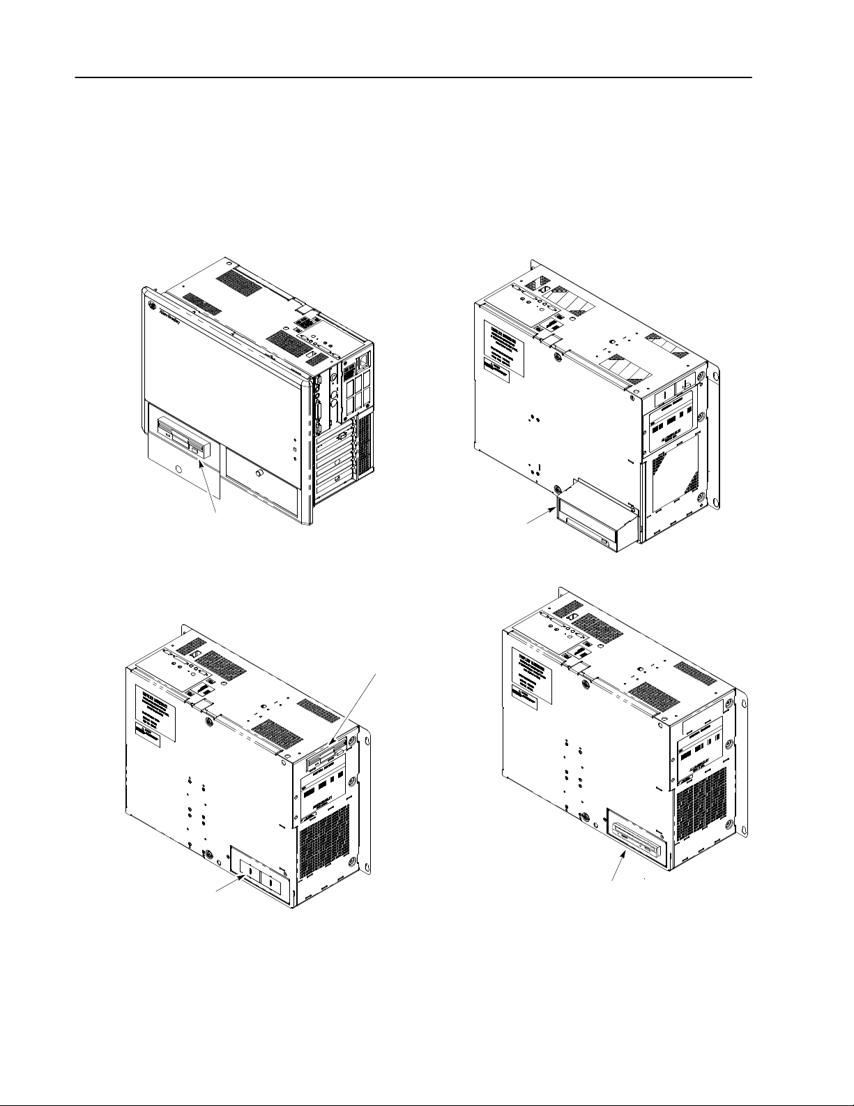
Front Mounting
(Floppy or CD ROM Drive)
Both the Floppy and CD ROM drives may be front or rear mounted.
With an optional mounting bracket, the floppy drive may also be
mounted in the side facing upper bay (refer to installation
instructions provided with bracket). The following figure shows the
methods of mounting a drive. The front mounting option is not
available for the non-display, metal bezel versions of the 6180
Computer.
Rear Mounting
(CD ROM Drive)
Shown with Cover (6189-RCDBRKT)
Accessory Drive Panel
Knockout for Rear Mounting
Upper Bay Mounting
(Floppy Drive)
Requires a mounting bracket (Catalog No.
6189-UBFDBRKT)
Instructions are provided with bracket.
Rear Mounting
(Floppy Drive)
Page 3
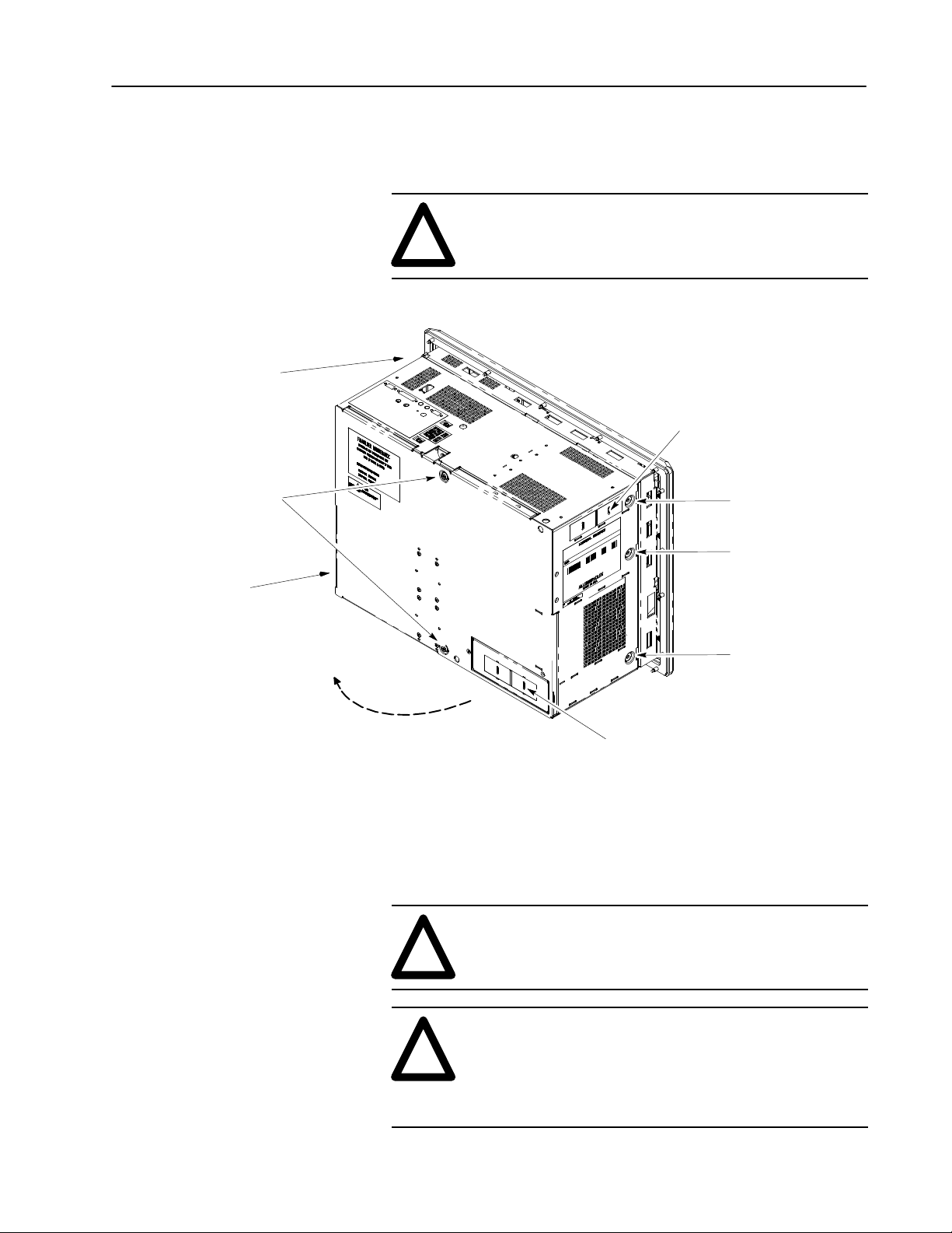
Front Bezel
Hinge On This Side
Back Panel
Retaining Screws
Removeable Media 3
To remove a front or rear facing drive:
1. Disconnect power from the 6180 Computer.
ATTENTION: Disconnect all power before
adding/removing components. Failure to disconnect
!
2. Remove the back panel.
power could result in severe electrical shock or damage
to the 6180 Computer.
Chassis Knockout
For Upper Bay Mounting
Back Panel
Chassis Swings Away
From Bezel
3. To remove the drive, it may be helpful to swing the chassis away
from the front bezel. Remove the three latching screws that
secure the front bezel. Note the following precautions before
swinging the chassis away from the bezel.
!
Front Bezel
Latching Screws (3)
Cover Knockout
for Rear Mounting of Drive
ATTENTION: Remove all cables from the the side
panel connectors. Failure to remove cables may cause
damage to the cables and connectors.
ATTENTION: If the 6180 Computer is installed with
mounting clips, the mounting clips on the hinge side
!
will interfere with the opening of the hinge. Remove
the mounting clips on the hinge side before swinging
chassis away from the bezel. Failure to remove clips
may damage clips and the chassis.
Page 4

Removeable Media4
4. From the bottom of the chassis (under the accessory drive),
remove the 4 screws that secure the accessory drive/ bracket
assembly.
Accessory Drive /
Bracket Assembly
Mounting Screws (4)
6180 Computer
(Bottom View)
5. The sequence of the following steps depends on whether the drive
is mounted to the rear or front:
• If mounted for front access, do step 6 then step 7.
• If mounted for rear access, do step 7 then step 6.
6. Disconnect the ribbon cable connector and power cable connector
from the drive.
Floppy or CD ROM Drive
Mounting Bracket
Not Illustrated
Power Connector
Ribbon Cable
7. Remove the accessory drive / bracket assembly through the back
of the chassis.
Page 5

Floppy Drive Bracket
(Catalog No. 6189-LBFDBRKT)
Removeable Media 5
8. If you are removing a floppy drive, remove the screws which
secure the floppy drive to the bracket. CD ROM drives do not
have a bracket and are mounted directly to the chassis.
Drive Mounting Screws (4)
Floppy Drive
To install a front or rear facing drive:
1. If installing a floppy drive, secure the floppy drive to the floppy
drive bracket. The CD ROM drive does not require a bracket.
2. Position the CD ROM or floppy drive / bracket assembly into the
chassis.
3. Connect the cable connectors to the drive. Connectors are keyed
so they cannot be installed backwards.
4. Align the CD ROM or floppy drive / bracket with the chassis
mounting holes and secure with the mounting screws:
• front facing CD ROM requires 4 screws
• rear facing CD ROM drive requires 2 screws
5. Swing the chassis back onto the bezel and secure chassis with the
three latching screws.
6. Install the back panel and the accessory drive panel.
Page 6

Removeable Media6
Notes:
You may have to remove the panel knockout (shown on page 2) if
a rear mounted floppy drive was not previously installed.
If you are installing a front facing CD ROM drive, a rear cover
(Catalog No. 6189-FCDBRKT) should be installed on the back
panel.
If you are installing a rear facing CD ROM drive, covers (Catalog
No. 6189-RCDBRKT) should be installed on the front bezel and
rear panel.
For additional information on mounting brackets and covers, refer
to the 6180 Industrial Computer Accessory Mounting Brackets
and Covers publication.
7. Apply power to the 6180 Computer and verify operation of the
drive. You may need to update the BIOS settings, refer to the
Processor Board manual.
CD ROM Emergency Eject
If the eject button will not eject the CD tray, use the following
emergency eject procedure.
1. Turn off the power to the computer and wait approximately 1
minute to allow the CD to stop spinning.
2. Insert a paper clip into the emergency eject hole and push in as
shown below. The tray will open.
Page 7

Removeable Media 7
CD ROM Disk Holders
Floppy Drive Specifications
The disk holders are not required for operation with the 6180
computer. The disk holders retain the CD if the CD ROM drive is
mounted in a vertical orientation. The 6180 computer can only be
mounted in an orientation where the CD ROM drive is in a
horizontal position.
The following table provides operating and technical specifications
for the 1.44MB floppy drive (Catalog No. 6189-FD144/A).
Format 3.5 inch Micro Floppy Disk*
Capacity 1.44MB (IBM Format)
Speed of Rotation 300 RPM
Continuous Speed Variation
Instantaneous Speed Variation
Access Time
Track to Track Slew Rate 3ms
Head Setting Time 15ms (maximum)
Average Access Time 94ms
Motor Start Time 500ms (maximum)
Rotational Latency 100ms (average)
Structure
Track Density 135 Tracks per Inch (TPI)
Number of Cylinders 80
Number of Tracks 160
Read/Write Heads 2
Data Rate 500K Bits/sec
Average Power 1.5 watts (typical)
Supply Voltage
* Use only high density floppy disks
1.5%
3.0%
+5V DC 10%
Page 8

CD ROM Drive Specifications
The following table provides operating and technical specifications
for the CD ROM Drive (Catalog No. 6189-CDROM).
Rotational Speed 6,360 rpm (Max)
Sustained Data Transfer Rate
Mode 1 Approximately 2,400 KBytes/s
Mode 2 Approximately 2,736 KBytes/s
Access Time
Average Random Access Time 100ms (Typical)
Average Random Seek Time 95ms (Typical)
Average Full Stroke Access Time 180ms (Typical)
Supply Voltage
Vibration
Operating
Non Operating
➀
➀
Shock
Operating
Non Operating
➀
➀
Temperature
Operating
Non Operating
➀
The 6180 computer specification for shock and vibration exceeds the
specifications for the CD ROM drive. When a CD ROM drive is installed and
operating, derate the shock and vibration specification for the 6180 computer to the
specifications for the CD ROM drive.
+5V, +12V DC 5%
No Hard Error
5 to 500 Hz 2.45m/s
2
(0.25G) (0-P)
5 to 10 Hz 5mm (P-P)
10 to 500 Hz (1G) (0-P)
No Hard Error
2
14.7 m/s
(1.5G) – Horizontal
2
(0.8G) – Vertical
7.8 m/s
Half Sine Wave 11ms/10s Interval)
Refer to 6180 Computer Specifications
C to 50C (41F to 122F)
5
C to 60C (14F to 140F)
-10
Allen-Bradley, a Rockwell Automation Business, has been helping its customers improve
productivity and quality for more than 90 years. We design, manufacture and support a broad
range of automation products worldwide. They include logic processors, power and motion
control devices, operator interfaces, sensors and a variety of software. Rockwell is one of the
world’s leading technology companies.
Worldwide representation.
Argentina • Australia • Austria • Bahrain • Belgium • Brazil • Bulgaria • Canada • Chile • China, PRC • Colombia • Costa Rica • Croatia • Cyprus • Czech Republic • Denmark
Ecuador • Egypt • El Salvador • Finland • France • Germany • Greece • Guatemala • Honduras • Hong Kong • Hungary • Iceland • India • Indonesia • Ireland •Israel • Italy
Jamaica • Japan • Jordan • Korea • Kuwait • Lebanon • Malaysia • Mexico • Netherlands •New Zealand • Norway • Pakistan • Peru • Philippines • Poland • Portugal • Puerto
•
Qatar • Romania • Russia–CIS • Saudi Arabia • Singapore • Slovakia • Slovenia • South Africa, Republic • Spain • Sweden •Switzerland • T aiwan • Thailand • Turkey
Rico
United Arab Emirates • United Kingdom • United States • Uruguay • Venezuela • Yugoslavia
Allen-Bradley Headquarters, 1201 South Second Street, Milwaukee, WI 53204 USA, Tel: (1) 414 382-2000 Fax: (1) 414 382-4444
Copyright 1997 Allen-Bradley Company, Inc. Printed in USA
40061-365-01(C)
•
•
•
 Loading...