

Page 1
Industrial 17" CRT Monitor
(Bulletin 6159 - Series B)
Installation and User Manual
Page 2
2 Table of Contents
7
7D
DEOH R
EOH RI
Industrial 17" CRT Monitor.............................................. 3
Description........................................................................... 3
Package Contents................................................................. 4
Installing the 6159 Industrial Monitor ................................... 5
Panel Mounting.................................................................... 6
Connecting the 6159 Industrial Monitor................................ 12
Operating the 6159 Industrial Monitor.................................. 16
Routine Maintenance............................................................ 27
Troubleshooting................................................................... 28
Appendix A: Touchscreen Serial Interface........................ 30
Description........................................................................... 30
Setting Up the Touchscreen Interface.................................... 30
Performing a Calibration...................................................... 32
Appendi x B : Video Ca bl es ................................................. 33
Specificat io ns...................................................................... 34
I &RQWH
&RQWHQ
QWV
WV
Important U s er Info rmation
Solid state equipment has operational characteristics differing from those of
electromechanical equipment. "Safety Guidelines for the Application, Installation, and
Maintenance of Solid State Controls" (Publication SGI-1.1) describes some important
differences between solid state equipment and hard-wired electromechanical devices.
Because of this difference, and because of the wide variety of uses for solid state
equipment, all persons responsible for applying this equipment must satisfy themselves
that each intended application of this equipment is acceptable.
In no event will Rockwell Automation be responsible or liable for indirect or
consequential damages resulting from the use or application of this equipment.
The examples and diagrams in this manual are included solely for illustrative purposes.
Because of the many variables and requirements associated with any particular
installation, Rockwell Automation cannot assume responsibility or liability for actual
use based on the examples and diagrams.
No patent liability is assumed by Rockwell Automation with respect to use of the
informat ion, cir c uits, equipment, or s oftware described in this ma nual.
Reproduction of the contents of this manual, in whole or in part, without written
permission of Rockwell Automation is prohibite d.
Throughout this manual, we use notes to make you aware of safety considerations.
ATTENTION: Identifies information about practices or
circumstances that can lead to personal injury or death,
property damage, or economic loss.
Important:
application and understanding of the product.
Identifies informat ion that i s especi al ly important for succes sful
Publication 6159-5.1
Page 3
,QGXVWULDO
,QGXVWULDO
&57 0RQLW
Industrial 17" CRT Monitor 3
&57 0RQLWR
RU
U
Description
The Bulletin 6159 17" Industrial CRT Monitor is a general purpose
monitor suitable for a wide range of industrial computing applications. It
offers the following features:
• Reliable and rugged industrial design
• High-brightness
• Durab le NEMA 4 sealed poly carbonate scr een overlay
• Versatile multi-sync design (640 x 480 to 1280 x 1024 resolution)
Note:
This monitor can display resolutions up to 1280 x 1024.
If you experience u n exp ected results opera t ing th e
monitor at this resolution, verify that the monitor is
oper ating at 60 Hz.
ATTENTION: The equipment described in this
document generates, uses, and emits radio frequency
energy. The equipment has been t ested and found to
comply with FCC Rules, Part 15, subpart J, for Class A
computing devices.
The use of non-shielded interface or power cords with
All e n-Bradley indust rial monitors is prohibited.
ATTENTION: X-ray emissions from these monitors are
typically about 0.05 mR/hr maximum, well below the 0.5
mR/hr maximum recommended by t he US. D ep art me nt of
Heal th and Human R esources an d specified in "Federal
Perf orman ce Standar ds for Television Receivers" , Section
10, Part 1020, Title 21, of the U. S. Code of Regulation
(PL90-620), Vol. 38, No. 198.
These m onitors are equippe d wit h X-ray protect ion
circuits which cause automatic shutdown of the
equipment i n cas e its X-r ay emissions begin to ap pr oach
Feder al limits .
Publication 6159-5.1
Page 4

4 Industrial 17" CRT Monitor
Availab l e O pt ions
The following options are available to the 6159 Industrial Monitor:
Video interface options (HD-15)
•
Touchscreen options (r esist i v e, ca p acitive)
•
Touchscreen cable optio ns
•
Video ca ble options
•
Power cord options
•
Package Contents
The monitor shipping carton contains the following items:
Monitor
•
Pa cka g e of mou nt i ng ha r dwa r e
•
AC power cord (optional)
•
Video cable (optional)
•
This user manual
•
A 6159 Industrial Monitor with a touchscreen option is shipped with
these additional items:
Supporting software and manuals
•
RS-232 serial extension cable (optional)
•
Un packing the Unit
Before unpacking a new monitor, inspect the shipping carton for
damage. If damage is visible, immediately contact the shipper and
request assistance. Otherwise, proceed with unpacking.
Publication 6159-5.1
Note:
Make s ure you keep t he ori ginal packa ging f or the monitor
in case you need to return the monitor for repair.
Page 5

Industrial 17" CRT Monitor 5
Installing the 6159 Industrial Monitor
This section describes how to install the monitor.
Tools Needed
In addition to the tools required to make the cutout, you will need the
following tools:
3/8” Deep Well Socket
•
1/4” Drive Extension - 12” or longer
•
1/4” Drive Ratchet or 1/4” Drive Torque Ratchet
•
Before Installation
When installing the unit, it is important to consider environmental
factors at the site that could affect performance as well as possible
effects from equipment operation on personnel and nearby equipment.
Following the guidelines will help ensure that the monitor will provide
safe and reliable service.
Ensure that sufficient power is available from a single phase AC
•
outlet at the site.
Ensure that sufficient space is available around air inlets and outlets
•
to provide the circulation necessary for cooling. Never allow air
passages to become obstructed. The monitor is equipped with a fan
to ensure proper cooling.
• Dust and smoke part icl es ca n ca us e pr obl ems , s ince they can collect
at ventilating holes in the enclosure and interfere with cooling.
Accordingly, where d ust and smo ke are problems i t is especially
important to keep air vents clean. Refer to the Routine Maintenance
section (Page 27) for more information.
Ensure that the ambient air temperature will not exceed the
•
specified maximum temperature. A user supplied fan, heat exchanger
or air conditioner may be required to meet this condition in some
installations.
Leave the m onitor’s enclosure or cover in place at all times during
•
oper ation. The c over affords prote c tion against high volt ages inside
the monitor and inhibits radio-frequency emissions that might
interfere with other equipment.
The Federal Communicat ions C o mmissi on has p repared a pa mph let
•
that addresses the pr oblem of radio frequency interference to radio
and television recep tion, whi ch should be cons ulted in case of
problems with such interference. This publication, “How to Identify
and Resolve Radio/TV Interference Problems” (Stock #004-00000345-4) may be obtained from the US. Government Printing Office,
Wa shington, DC 20402.
Publication 6159-5.1
Page 6
6 Industrial 17" CRT Monitor
Determine the mini mum and ma x imum ambient hu midi t y for the
•
monitor by consulting the specification sheets at the back of this
manual. Ensure that the humidity of the ambient air will not exceed
these limits. In very dry environments, static charges build up very
rea dily. Proper gr oundi ng of the equ i pment through the AC p ower
cord can help reduce the likelihood of static discharges, which may
cau se shoc ks and damage electronic compone nts.
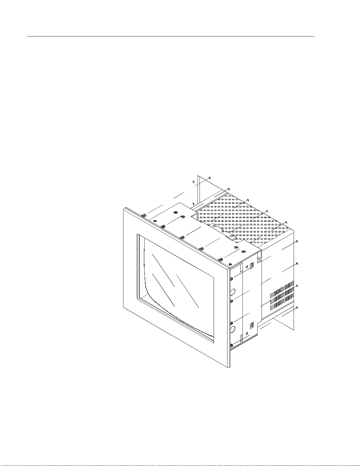
Panel Mounting
When properly installed, the 6159 Industrial Monitor is designed to
provide p rotection agai nst wa ter a nd dust to NEM A 4 standards.
No slides or shelves are required because the 6159 Industrial Monitor is
designed to be supported by the panels in which it is installed.
Figure 1
Generic Panel Mount Diagram
Publication 6159-5.1
Page 7
Industrial 17" CRT Monitor 7
Panel Mounting Guidelines
Observe the following precautions before installing the unit in a panel:
Confirm that there is adequate space behind the panel . Remem ber to
•
allow extra space (63.5 mm (2.5 in) behind and25.4 mm (1 in) below
and on each side) for a i r circ ulat ion and cabli ng. Allow 12.7 mm
(0.5 in.) top clearance for mounting.
Confirm that the cabinet is deep enough to accommodate the
•
monitor's depth while providing rear clearance for airflow. A cabinet
with depth of 449.3 mm (17.69 in.) is sufficient.
Take precautio ns so that metal cuttings do not e nter any comp onents
•
that are already installed in the panel.
Supporting panels should be at least 14 gauge to ensure proper
•
sealing against water and dust and to provide proper support. The
mounting hardware supplied accommodates panels up to 6.4 mm
(0.25 in) thick.
Note:
Supporting panels must be cut and drilled to
specifications prior to installation.
ATTENTION: Failure to follow these warnings may
result in personal injury or damage to the panel
components.
Publication 6159-5.1
Page 8
8 Industrial 17" CRT Monitor
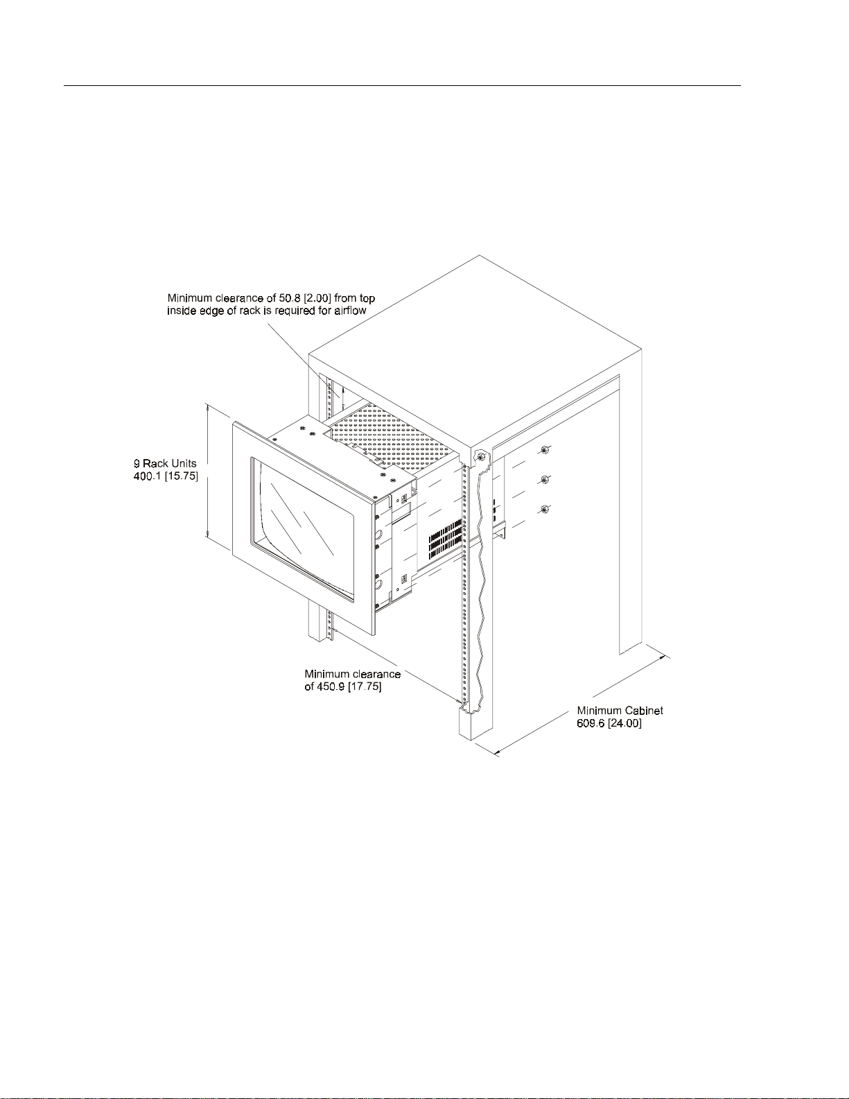
Mounting the 6159 Industrial Monitor in a Rack
Due to the front panel size and stud pattern, the 6159 Industrial Monitor
can be installed in an EIA 19” 9U panel standard rack. Refer to the
following figure:
Figure 2
Generic Rack Mounting Diagram
Publication 6159-5.1
Important:
If you install the 6159 Industrial Monitor in a rack, you
must ensure that the rack can support the weight of the
monitor.
You might need to install a support or shelf under the rear
of the monitor to support the weight.
Page 9
Industrial 17" CRT Monitor 9
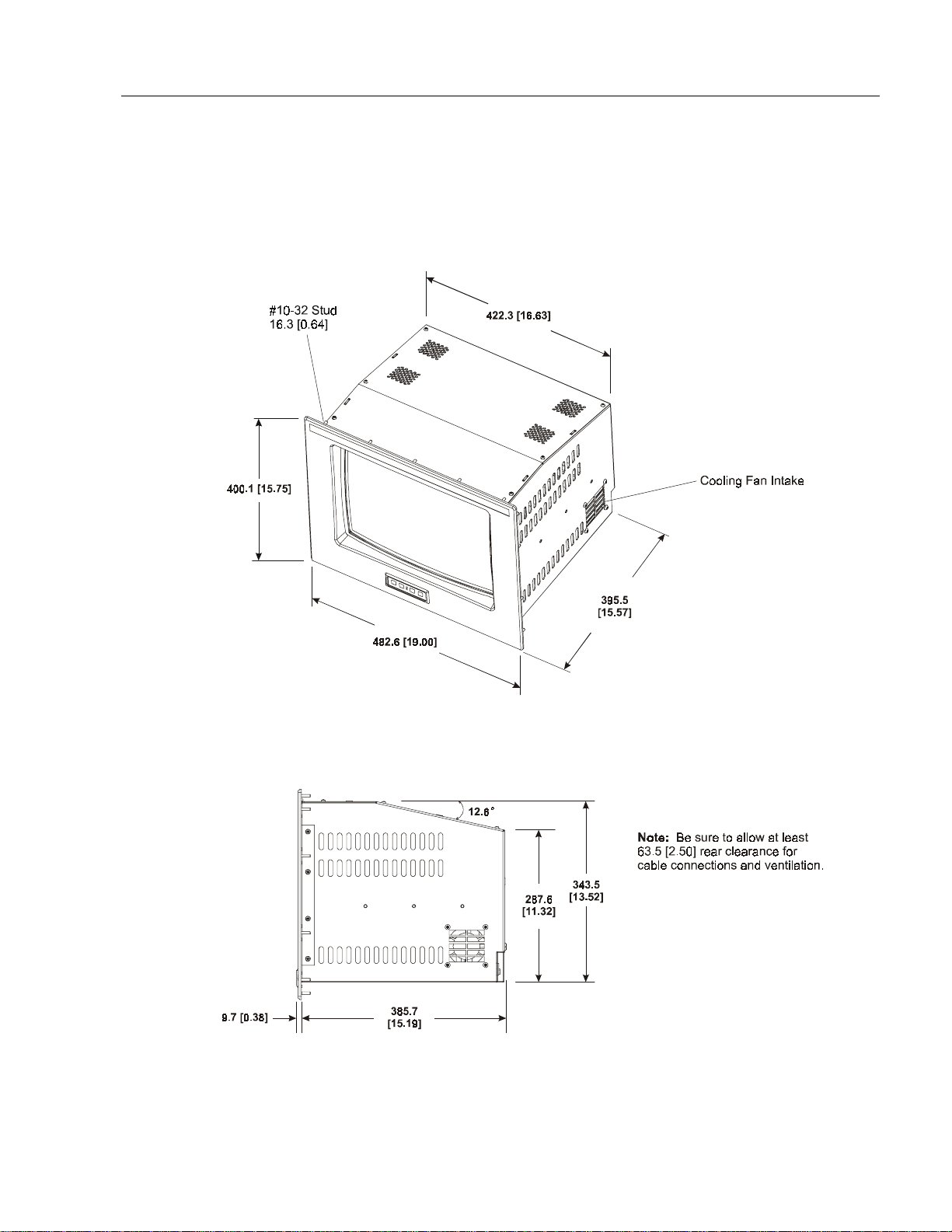
Dimensions
This section provides diagrams you need to follow to install the unit.
Figure 3
6159 Industrial Monitor Dimensions
Publication 6159-5.1
Page 10
10 Industrial 17" CRT Monitor
Panel Mounting Procedure
1. Confirm that the shipping carton contains a package of 20 10-32 lock
nuts and 20 flat washers. You will ne e d 18 nut s and washers for
installation.
2. Refer to th e physic al dimension dr awing (Figure 3) and co nfir m t hat
th ere is adequate space b ehin d the p ane l. R emember to al low extra
space for c i rculation and c abli ng.
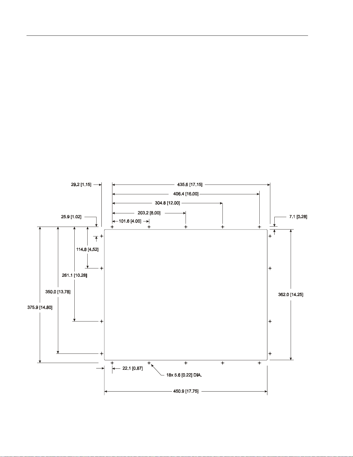
3. Refer to the pa nel cutout drawing below for dimensions of the panel
cutout and mounting hole locations. Cut and drill the panel.
Note:
Figure 4
Panel Mounting Cutout
Use #10-32 or M5 self-locking nuts for mounting.
Publication 6159-5.1
Page 11
Industrial 17" CRT Monitor 11
4. Carefully remove the monitor from its packaging. Avoid damaging
the monitor gasket.
Tip: It will be easier to install the monitor if you support it with a shelf
or other support adjusted to the appropriate height.
5. Insert the monitor in the panel cutout from the front. Do not damage
the threaded mounting studs as you position the monitor.
6. Secure the unit with the lock nuts and washers provided. Tighten
evenly to 24 inch-pounds of torque.
Important:
To ensure a proper seal, be sure to install a washer and
nut on each of the 18 mounting studs.
ATTENTION: Mounting nuts must be tightened to a
torque of 24 inch-pounds to provide panel seal and
avoid potential damage. Rockwell Automation
assumes no responsibility for water or chemical
damage to the monitor or other equipment within the
enclosure due to improper installation.
7. Remove the protective adhesive sheet from the screen of the
Industrial Monitor. The sheet is designed to prevent scratching of
the polycarbonate screen protector or the optional touchscreen
during shipping and installation. It should be removed before use.
Publication 6159-5.1
Page 12
12 Industrial 17" CRT Monitor
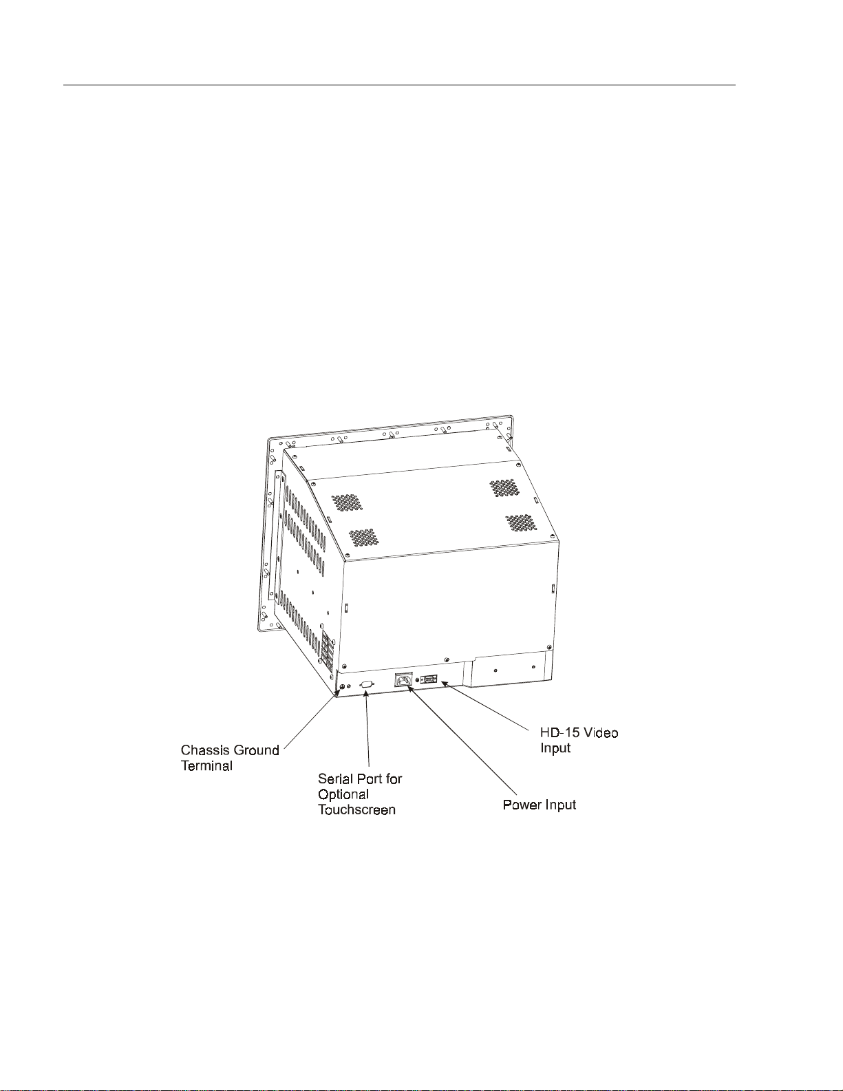
Connecting the 6159 Industrial Monitor
The rear panel of the 6159 Industrial Monitor has connectors for
attaching cables to accomplish the following:
Connecting to a host video source (HD-15 VGA)
•
Connecting to a host t ouchscreen control port (DE-9 conn ector)
•
(optional)
Connecting to AC power
•
Note:
Some connectors on your monitor may differ from the
following figure.
The following figure illustrates the standard configuration for the 6159
Industrial Monitor.
Figure 5
Rear Panel
Publication 6159-5.1
Page 13

Industrial 17" CRT Monitor 13
Connecting the Video Source
The video connection to the host is made through a HD-15 (female)
connector.
To establish a signal using the HD-15 connector:
Note:
1. Obtain a shielded, properly terminated video cable of length as short
as possible. Longer cables (up to approximately 50 feet in some
cases) may be used, provided they are properly constructed. Your
package may include a 6- or 15-foot video cable, if specified.
2. Connect one end of the cable to the female HD-15 video input
connector on the rear panel of the monitor.
3. Conn e c t the other en d to th e ou tput of any I BM-co mpatible VGA
ada pter or other vide o generat or.
Note:
For more information on using an HD-15 video cable to
connect to the host computer, refer to Appendix B
(Page 33).
You may connect the monitor to video generators that
do not conform to VGA standards. The main
requirement is that the generator provide analog RGB
video signals (0.714V or 1V above reference black into
75 oh ms) and separat e horizontal and ver tica l sync
signals. For information on setting the video input
level, refer to Page 25.
Publication 6159-5.1
Page 14

14 Industrial 17" CRT Monitor
Connecting the Touchscreen Interface
The serial touc hscreen interfa ce connection to th e host is made through
an RS-232 DE-9 (female) connector located on the rear panel.
The optional touchscreen provides a high-resolution touch input system.
Driver software included with the package allows the touchscreen to
function with many popular DOS and Windows
applications as a pointing device (mouse).
®
-based industrial
Note:
Refer to the manual included with the touchscreen option
and Appendix A of this manual (page 30) for additional
details on the installation and operation of the touchscreen.
To connect the touchscreen:
1. For units with the touchscreen option, make sure you have one of the
opti onal serial c ables .
2. Connect one end of the touchscreen serial cable to the T/S port
connector on the rear of the monitor.
3. Conn e c t the other en d to any serial co mmunications port on th e host
computer.
4. Tighten the captive screws on the cable connector to secure it.
Publication 6159-5.1
Page 15

Industrial 17" CRT Monitor 15
Connecting AC Power
The 6159 Industrial Monitor requires a single phase power supply
providing 100 to 240V AC at 50 or 60 Hz. Power must be available at a
grounded thr e e-pin outl et loca ted nearb y. When e ver possible, c onnec t
the monitor to the same AC source that supplies the computer.
To connect AC power to the monitor:
1. Turn off the mai n switch or breaker.
2. Use the ground terminal of the monitor to establish a chassis-to-earth
ground connection. Secur e one e nd of a ground s trap to the ground
termina l. Conn e c t the other e nd of th e ground str ap to a good earth
ground.
The ground terminal is an M5 screw.
A TTENTION: Chassis ground must be connected for
safe operation of the monitor. The AC receptacle on the
monitor is a 3-wire type with chassis ground pin, and the
mating AC cord supplied is a 3-wire type, designed for
connection to a grounded 3-pin AC outlet. However, a
properly ground AC ou tlet is not always ava ilable, and
grounding using a 3-wire cord can easily be defeated. If
you fail to ground the monitor properly, the setup may
resu lt in p ersona l injur y f rom electric al sh ock or damage
to the equipment.
3. Connec t the socket end of the AC power cord to th e mat ing
connector on the rear panel of the monitor.
4. Connect the plug end of the AC power cord to the main outlet.
5. Restore AC power to the outlet.
Publication 6159-5.1
Page 16

16 Industrial 17" CRT Monitor
Operat i n g th e 6159 Industrial Monitor
This section describes how to operate the 6159 Industrial Monitor.
Operator Controls and Indicator s
The 6159 Industrial Monitor is furnished with operation keys on the
front panel that allow di g ital on- scre e n adjus tments . On-sc reen
adjustments are performed from th e main me nu (se e figure on followi ng
page). Using the operation keys (see below figure), the user can
maneuver to the appropriate selection or setting in the menu.
Figure 6
Front Panel Operation Keys
Table A
Operation Keys Description Table
<
Control Description
This operation key:
•
Displays the main menu.
•
Records changes made to the selection when the control box for a desired
selection is displayed. The control box closes and the main menu is displayed.
•
Closes the main menu. This action memorizes any settings and completes the
adjustments.
•
Answers “Yes” to questions.
and
>
Arrow keys have several functions:
•
If the main menu is displayed, pressing these keys moves the cursor to desired
selection that needs adjusting. Arrow keys to move to the left(<) and to the right (>).
•
If a control box is displayed, may be used to select a value for the adjustment.
•
If no menu is displayed, pressing these keys adjusts the contrast.
This operation key:
•
Displays t he con trol b ox for t he highlighted select ion when the main menu is
displayed.
•
Displays the secondary control box for the highlighted selection when a control box
is displayed.
•
Toggles between the control box and any of its secondary control boxes.
•
Answers “No” to questions.
Publication 6159-5.1
Page 17

Industrial 17" CRT Monitor 17
Status LEDs
The 6159 Industrial Monitor has two status LED indicators on the front
panel. The following table lists the functions assigned to the LEDs:
Table B
6159 Industrial Monitor Status LED Indicators
LED Description
Power LED (Green)
•
Indicates that power is applied to the monitor.
Status LED (Amber)
Note:
For information on troubleshooting the 6159 Industrial
•
Indicates that the monitor is not receiving a
video signal.
Monitor, refer to Page 28.
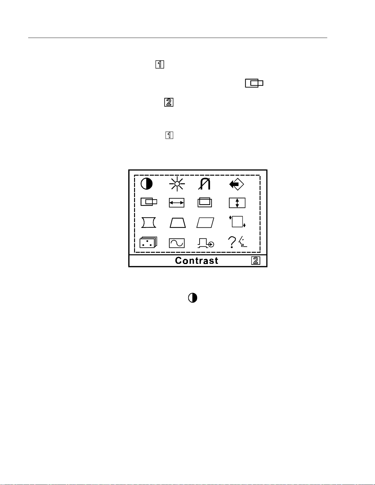
Operating the Main Menu
This section explains the digital main menu and explains how to make
oper ation adjustments .
To display the main menu:
Press
on the screen.
Figure 7
Main Men u
to display the menu. The main menu (see below figure) appears
The user can make all the necessary adjustments by making selections in
the ma in menu using one or all of th e opera tion k e ys. T he follo w ing
pages describe how to make these individual adjustments.
Before advancing to these adjustments, the user needs to understand the
basic procedure in using the operation keys. To aid in this understanding,
a sample procedure is provided below:
Publication 6159-5.1
Page 18
18 Industrial 17" CRT Monitor
Sample Procedure (Adjusting the Horizontal Position):
1. Press
2. Use the arrow key s to maneuver to the
3. Click o n
4. Use t he arrow keys to reach the desired value.
5. Press the
adjustments.
Main Men u
to display the main menu.
to disp lay the adjustment box for horizontal pos ition.
key to memorize the settings and complete the
icon.
Publication 6159-5.1
Contrast Control
Use t h e contras t contr ol to vary the d i f fere nce between t he display' s light
and dark elements. The optimum setting ma y vary slightly with different
typ es of displays and changes in amb ient lighting, as well as ind ividual
taste. Use this control to adjust the screen contrast to match the
brightness level in the room.
The operator c an vary the contra st one o f two dif ferent ways:
Direct Operation
If the main menu is not displayed, the user can use the arrow keys to
adjust the contrast.
Press
•
•
< to decrease the contrast of the image.
Press > to increase the contrast of the image.
Page 19

Industrial 17" CRT Monitor 19
Note:
Using the Contrast adjustment box
1. Display the Contrast adjustment box.
2. Use the arrow key s to sel e ct a value.
•
•
3. Press the
adjustments.
Pressing the arrow keys simultaneously sets the standard
level.
< to decrease the contrast of the image.
Press
Press
> to increase the contrast of the image.
key to memorize the settings and complete the
Brightness Control
Use the brightness control to adjust the overall intensity of the display.
After allowing the CRT to warm up for at least a minute, adjust for the
least amount of brightness needed to make the display clearly viewable.
Adjust the brightness to match the brightness level in the room so that
the level will be easy to see.
1. Display the Brightness adjustment box.
2. Use the arrow key s to sel e ct a value.
•
•
Note:
3. Press the
adjustments.
< to decrease the brightness of the image.
Press
> to increase the brightness of the image
Press
Pressing the arrow keys simultaneously while the
Brightness adjustment box is displayed sets the
standar d level.
key to memorize the settings and complete the
Degaus s
The display screen is degaussed automatically each time the monitor is
powered on. This degaussing eliminates color impurities and other
distortions of the di splay by neut ralizing t he effe c ts of magnet i c fields in
the surrounding environment.
Publication 6159-5.1
Page 20

20 Industrial 17" CRT Monitor
When the unit is left on for a long period, or is repositioned following
power-up, the screen may pick up additional magnetic flux, causing
colors to appear "blotchy" or otherwise distorted. For full effectiveness,
all ow at least fi f teen minut es betwe e n manual degauss ings. Short er
int ervals may result i n an incomplete removal of f lux and residual c olor
impurities.
Note:
The internal degauss will not prevent color impurities
caused by local ma g netic fields. Metal encl osu res can
easily become magnetized by welding and machinery
operations.
Use a hand held degaussing coil to remove residual
magnetism from the enclosure.
Note:
If the unit is located near electric transformers, motors,
loudspeakers or other strong magnetic sources, degaussing
alone may not be sufficient to eliminate interference. Try
reorienting the unit relative to the magnetic source or
moving the monitor further away.
If this still does not solve the problem, c ontact Rockwell
Automation about magnetic shielding.
The degaussing operates for approximately five (5) seconds after
selection. In this duration, the front panel keys are not operational.
Memory Recall
Use this selection to return to the initial factory settings. A menu
displays asking if you want to return to the initial settings.
Publication 6159-5.1
1. Display th e Memory Recall adjus tment box.
2. Make the appropriate selections.
For YES, press
•
. This action recalls the original settings and
returns you to the main menu.
For NO, press
•
. This action returns you to the main menu
without recalling the original settings.
Note:
This adjustment box disappears after a 30-second
inactivity period.
3. Press the
key to memorize the settings and complete the
adjustments.
Page 21

Industrial 17" CRT Monitor 21
Horizontal Position
Centers the image horizontally on the screen.
1. Display the Horizontal Pos ition adjustment box.
2. Use the arrow key s to sel e ct a value
Note:
Press
•
Press
•
3. Press the
adjustments.
Pressing toggles between the horizontal size and
horizontal position control boxes.
< to move the image to the left.
> to move the image to the right.
key to memorize the settings and complete the
Horizontal Size
Makes the imag e wider or narrow er.
Note:
1. Display the Horizontal Size adjustment box.
Before adjusting the horizontal size, first center the image
in the screen.
Pressing
horizontal position control boxes.
toggles between the horizontal size and
2. Use the arrow key s to sel e ct a value
•
•
3. Press the
adjustments.
< to decrease the size of the image horizontally.
Press
> to increase the size of the image horizontally.
Press
key to memorize the settings and complete the
Publication 6159-5.1
Page 22

22 Industrial 17" CRT Monitor
Vertical Position
Centers the image vertically on the screen.
Note:
1. Display th e Vertical Posit ion adju stment box.
2. Use the arrow key s to sel e ct a value
•
•
3. Press the
adjustments.
Pressing toggles between the vertical size and vertical
position control boxes.
< to move the image down.
Press
> to move the image up.
Press
key to memorize the settings and complete the
Vertical Size
Makes the i mage taller or shor ter.
Note:
Before adjusting the vertical size, first center the image in
the screen.
Note:
1. Display th e Vertical Size adjustment box .
2. Use the arrow key s to sel e ct a value
•
•
3. Press the
adjustments.
Pressing toggles between the vertical size and vertical
position control boxes.
< to decrease the size of the image vertically.
Press
Press
> to increase the size of the image vertically.
key to memorize the settings and complete the
Publication 6159-5.1
Page 23

Industrial 17" CRT Monitor 23
Vertical Pincushion
Corrects the ima ge for barrel distortion.
1. Display the Vertical Pi nc ushi on adju stment box.
2. Use the arrow key s to sel e ct a value
Press
•
•
< to curve the scr een image’s edges inwards.
Press
> to curve the screen image’s edges outwards.
3. Press the
adjustments.
key to memorize the settings and complete the
Trapezoid
Corrects the ima ge for trapezoidal distortion.
1. Display the Trapez oid adjustme nt box.
2. Use the arrow key s to sel e ct a value
•
•
3. Press the
adjustments.
< to make the image narrower at the top.
Press
Press
> to make the image wider at the top.
key to memorize the settings and complete the
Parallelogram
Corrects the ima ge for parallelogram distortion.
1. Display th e Para llelogr am adjustment box.
2. Use the arrow key s to sel e ct a value
Press
•
•
3. Press the
adjustments.
< to skew the image leftward.
> to skew the image rightward.
Press
key to memorize the settings and complete the
Publication 6159-5.1
Page 24

24 Industrial 17" CRT Monitor
Rotation
Adjusts for tilt of the image on the screen.
1. Display the Rotation adjustment box.
2. Use the arrow key s to sel e ct a value
•
•
3. Press the
adjustments.
< to tilt the image to the left.
Press
Press
> to tilt the image to the right.
key to memorize the settings and complete the
Color Temperature
Adjusts the c olor white in an image (in Kelvin). The higher the
tem perat u re, the redder, or warmer, the i mag e color scheme. The lower
th e temper ature, the bluer, or colder, the image color sc heme.
Note:
1. Display t he Color Temperature adj ustment box.
2. Press the
selections:
Before making any adjustments, r ecord th e i n itial c olor
setting because memory recall will not reset this value.
< and > arrow keys to make one or the following
Publication 6159-5.1
1
: 9300K
•
2
: 6550K
•
3
: Us er- defined temperature value
•
3. If you selected “3”, the
the Color Adjustment control box. This instructs the user to press
to dis p lay the User C olor Adjust me nt cont rol box ..
4. To enter a user- defin e d value, you mus t manu ally set t he red, green,
and blu e va lu es.
icon displays in the lower-right corner of
Page 25

Industrial 17" CRT Monitor 25
5. To adjust the value, press
Press the
color (0-255).
6. Press the
adjustments.
< and > arrow keys to adjust the value of the selected
key to memorize the settings and complete the
to advance to the appropriate color.
Displ ay Fr eq u ency
This option displays the input synchronization signal frequency. Display
the Display Frequency adjustment box to view signal.
Video Input Level
This option allows the user to match the video input signal level to the
computer being used. The user can choose from one of two selections
(0.7V or 1V).
1. Display the Video Input Level adjustment box.
2. Press
to toggle to the correct selection.
3. Press the
adjustments.
key to memorize the settings and complete the
Language Selection
The user can alter the language of the on-screen menu. Selections
include G erman, French, English, I talia n, and S panis h.
1. Display the Language Selection adjustment box.
2. Press the
3. Press the
adjustments.
< or > arrow keys to move
key to memorize the settings and complete the
to the correct selection.
;
Publication 6159-5.1
Page 26

26 Industrial 17" CRT Monitor
Self-Test Menu (NO SIGNAL screen)
Figure 8
Self-T est Menu
This screen indicates that the monitor is working properly. Press one of
the 4 front panel operation keys to call the appropriate adjustment box if
one of the fo llowi ng conditi ons occu r:
• The input synchronization signal is out-of-range.
• The unit entered a power-saving mode (only displayed in the OFF
STATE).
• There is no signal (not connected to the computer, computer is OFF,
etc.).
Table C
Recommended Size Settings Table
Ver t ical Size Horizontal Size
4:3 Aspect
225mm (8.9 in.) 300mm (11.8 in.)
Publication 6159-5.1
Page 27

Industrial 17" CRT Monitor 27
Routine Maintenance
Cleaning
Occasionally clean the display panel and cabinet with a soft cloth
dampened (not soaked) with a mild (non-abrasive) glass cleaner. Keep
turning a f resh side of the cl oth towar d the screen surface to a void
scratching it with accumulated grit.
Note:
Special care sh ould be take n w hen cl eanin g a resistive touc hscr e e n or
polycarbonate shield that is installed over the screen. Abrasive and
certain chemical cleaners ca n easily d ama ge the surface.
The solvent should be applied only to the cloth, and not
directly on the monitor screen.
Do not use paper products as they ma y scratch t he surface.
To minimize the risk of abrasion, allow the screen to
sta nd dr y.
Replacing a Line Cord
To avoid s hock and fire hazards, the mo nitor’s po wer cord should be
replaced if the insulation becomes broken or if it develops a loose
internal conne c tion.
Other Maintenance
Qualified service personnel should perform all maintenance, except for
the power cord replacement described above.
Publication 6159-5.1
Page 28

28 Industrial 17" CRT Monitor
Troubleshooting
You can refer to this table to help identify the cause and offer a solution
to a problem. This table lists typical problems you may encounter.
Table D
Troubleshooting Table
Symptom Possible Proble m Action
No screen image and the green power
LED is not lit.
The green power LED is lit, but no screen
image when power switch is closed.
The amber status LED is lit, and no
screen im ag e.
No raster vis i ble even when br ig ht ness
and contrast are set full ON.
Raster di m l y vis ib l e wit h br ig htness and
contrast controls set full ON, but no
displ ay present
Display is pr esent, but g arbl ed or rolling Monitor n ot s ynched to video
Display is present and stable, but appears
“wrapp ed” at on e si d e or oth er wise not
properly centered or sized.
Display is present and stable, but missing
some co lor(s)
Display is present and stable, but colors
are not pur e
Power cord not connected.
No power available at AC outlet. Test AC outlet by plugging in a lamp or other
Power cord faulty. Replace power cord. Refer to Page 27.
Blown fuse. Have moni tor servic ed.
Monitor f aulty. Have moni tor servic ed.
Screen saver or power
manag em en t feature activated.
Brightness and contrast controls
not proper l y ad jus ted.
Monitor n ot s ynched to video
sourc e.
Monitor f aulty. Have moni tor servic ed.
Monitor ou t of ad jus t ment or
faulty.
Video cab l e pr ob l em. Check f or pr oper install ation of video c abl e( s ).
Fault in vid eo s our ce. Test vid eo s our ce by connect in g to another
Fault in monitor. Have monitor serviced.
sourc e.
Size and pos it ion controls n ot
proper l y adj us t ed.
Video cable problem. Check for proper video cable installation.
Fault in monitor. Have monitor serviced.
Monitor requires degaussing. Manually degauss the monitor. Refer to
Enclos ure requires degaussing. Manually deg aus s t h e enc l osure. Ref er to
Open power switch. Reconnect power cord at
monitor an d at AC out l et . Close power sw itc h.
known good devic e.
Disable screen saver by activating an input to the
host sys t em. Pr ess a key or move the m ouse to
cancel power save mode.
Adjust brightness and contrast controls.
Check for proper video cable installation. Replace
suspected faulty cable.
Check to ens ure that video s ource is oper at i ng
within th e m oni t or ’s r ang e.
Have moni tor servic ed.
Refer to installation instructions.
Replace suspected faulty cable (s).
monitor that is known to be operation al.
Refer to installation instructions.
Check for proper video cable installation. Replace
suspected faulty cable.
Check to ens ure that video s ource is oper at i ng
within th e m oni t or ’s r ang e.
Adjust c ontrols for pr op er siz e an d p osit ion of
displ ay. R ef er t o op erator instr uc ti ons
Replace suspected faulty cable.
Page 19.
Page 19.
Publication 6159-5.1
Page 29

Symptom Possible Proble m Action
Display is pr esent, but “jit ters” or is
severely distorted
Do not confuse the flicker
NOTE:
associated with an in t er l ac ed vi d eo m ode
with jitter.
Display is present, but “bars” appear
across it.
Connected monitor to computer. When
powered, the PC locked up
Interf eri ng external AC or DC
magnetic shield
“Noise” generated by other
equipment in the environment is
present at t h e vi d eo inputs
Graphics card driver is not
compatible with monitor
Industrial 17" CRT Monitor 29
If possible, reposition the monitor beyond the
prox imity of large transformers, motors, bus bars,
etc.
Ask Roc k well A ut om ation abou t various shi el ding
options avai l ab le to protect th e mon it or .
Consult t h e app lication n ot e wh ic h dis c us ses
method’s of eliminating noise.
Update t h e graphics card dri ver s to the latest
version.
Publication 6159-5.1
Page 30

30 Industrial 17" CRT Monitor
$
$SSHQGL[ $
SSHQGL[ $
,QWHUIDFH
,QWHUIDFH
7
7RX
RXF
FKVF
KVFU
UHHQ 6
HHQ 6H
HULDO
ULDO
Description
Setting Up the Touchscreen Interface
All touch controllers are configured by default to provide serial
communications at 9600 baud, 8 data bits, 1 stop bit, no parity.
For Allen-Bradley monitors equipped with touchscreens, a serial
communications cable is requ ired. A suitable cable can be obtained fro m
Rockwell Automation or you can create one.
The cable provides a communications channel between the touchscreen
controller, which is mounted inside the monitor, and an RS-232-C serial
port on the host computer. Because the touch controller obtains power
from the monitor's power supply, no external touch power connections
are necessary.
Software supplied with the touchscreen must be loaded on the host
computer to handle communications with the touch controller over the
channel.
Because t he touchscreen emu l ates a mouse, there may be c ompatibil i ty
issues involving how the touchscreen emulates mouse buttons, especially
multiple buttons. For a complete discussion of these issues and how to
troubleshoot them, refer to the touchscreen documentation.
This section describes how to set up the touchscreen system using the
6159 Industrial Monitor. Setup involves the following:
Publication 6159-5.1
• Enabling the touchscreen interface
• Installing the software on the host computer that will handle
communications with the touchscreen controller
• Performing a ca lib ration
Enabl ing th e To uchscreen Interf a ce
The 6159 Industrial Monitor provides a female DE-9 connector on the
rear panel. This connector provides the serial interface for the touch
controller.
Page 31

Industrial 17" CRT Monitor 31
Interconnecting wiring to the host serial port connection is shown in the
following table.
Table E
Touchscreen Interface
Monitor
(DCE Device) Host (DTE Device)
DE-9 (Female) Signal Description DE-9 (Male) DB-25 (Male)
1 Not Connected (DCD) 1 8
2 Transmit Data (TXD) 2 3
3 Receive Data (RXD) 3 2
4 Data Terminal Ready (DTR) 4 20
5 Common Signal Return (SG) 5 7
6 Not Conn ected (DSR) 6 6
7 Request To Send (RTS) 7 4
8 Clear To Send (CTS) 8 5
9 Not Conn ected 9 22
Installing the Touchscreen Driver Software
To install the touchscreen driver software correctly, obtain the following
information about the host hardware:
The COM port in use for the touchscreen. Ensure that the RS-232
•
cable is properly installed between the monitor port and the host’s
COM port.
The baud rate at which th e controller is oper ating. You will need to
•
match the baud rate at the COM port. The controller baud rate is
factory set at 9600.
Note:
If you are using older touchscreen software, you may be
prompted for the type of touchscreen controller being used.
The 6159 uses the following controllers:
Resistive: MicroTouch model SMT3V.
•
Capaciti v e: Micr oTouch model SM T3R.
•
Publication 6159-5.1
Page 32

32 Industrial 17" CRT Monitor
Once you have obtained this information, install the software using the
installation disks found in the touchscreen accessory package.
Performing a Calibration
Note:
After installing the driver software, follow the instructions in the
touchscreen documentation.
Following installation of the touchscreen software and calibration, the
touchscreen is ready to use.
Before installation, you may want to check the touchscreen
manufacturer’s site on the World Wide Web for the latest
software drivers. Enter the following address in your
Internet browser to access the manufacturer’s web site:
www.microtouch.com
Look for one of the following product names on the web
site:
TouchTek5 resistiv e touchscreen
•
ClearTek capacitive touc hscreen
•
Publication 6159-5.1
Page 33

Industrial 17" CRT Monitor 33
$
$SSHQGL[ %
SSHQGL[ %
You use an HD-15 video cable equipped with a conventional HD-15
connector at each end to connect the 6159 Industrial Monitor to the host
computer.
9
9LGHR &
LGHR &D
DEOHV
EOHV
Note:
Figure 9
HD-15 Video Connector
The following table provides the pin numbers and corresponding pin
assignments for the HD-15 vi deo connect or with the DDC2B ca pability:
Table F
Standard HD-15 Video Cable
Monitor HD-15
(Female)
The following figure is the view looking into the pin end of
the male connector or solder term end of the female
connector.
Signal Description
1Red Video 1
2 Gr een Video 2
3Blue Video 3
4 Ground 4
5 Ground 5
6 Red Video Ground 6
7 Green Video Ground 7
8 Blue Video Ground 8
9Not Used 9
10 Sync Ground 10
11 Ground 11
12 Bi-Directional Data (SDA) 12
13 Horizontal Sync 13
14 Vertical Sync (VCLK) 14
15 Data Clock (SCL) 15
Host
HD-15 (Male)
Publication 6159-5.1
Page 34

34 Industrial 17" CRT Monitor
Specifications
Display
CRT Type 17” diagonal flat square, 0.27mm dot pitch
Degauss in g Manual and au t om at ic
Nominal Display Area
(4:3 aspect) Horizontal
(4:3 aspect) Vertical
Diagonal
Non Linearity (CHP Method)
Horizontal
Vertical
Regul ati on 2m m m ax peak devi ation
Misconvergence 0.3mm max inside ce ntered circle 225mm dia.,
Lumin ance (typic al) 35 fL +/- 5% f L, s m all w hi te square
CIE coordinates
White x:=0.283, y:=0.298 (9300K +8MPCD)
RGB short persistence (Hi-EU Red)/Dark TINT,
Tension-band implosion protected
11.8in. (300mm +/- 3mm)
8.9in. (225mm +/- 3mm)
14.8in. (375.9mm)
7% max
6% max
0.4 max outside
Video
Resolution 640 x 480 to 1280 x 1024 (m onitor will s ync t o 1280 x
Supported Standards IBM VGA (640x480 at 60Hz )
Horizontal Scan Rate Variable: 30k Hz to 70kHz
Vertical Scan Rate Variable: 50Hz to 180Hz
Retra ce Times
Horizontal
Vertical
Video Bandwidth 86 MH z
Video Input Signal RGB analog (white level = 0.714V above ref. black,
Sync Input Signals Separate Horizontal and Vertical Sync Control, TTL
Inpu t Connection HD-15
Controls and Indicators
1024, though tube dot pitch 1024 x 768
VESA (640x480 at 60/72Hz, 800 x600 at 56/6 0/72H z,
1024x7 68 at 60/ 70Hz)
DEC (1024x864 at 60Hz, 1280x1024 at 66/72Hz)
2.7 usec m ax
0.475 msec max
into 75 Oh ms , sin gle ended)
signal l evel s
Sync on green ( 0. 28 6V b el ow ref . bl ac k) or
Composite separate (into 75 Ohms, single ended)
Front Panel: operation keys access on-screen
display (H Size, H Pos, V Size, V Pos, Contrast,
Brightness, Manual Degauss, Raster Rotation, etc.)
Publication 6159-5.1
Operator Input
Touchscreen Option: Resistive or capacitive
touchscreen, with serial controller and driver software
Page 35

Industrial 17" CRT Monitor 35
Environmental
Panel Rating NEMA 4/12, designed to IP65 standards
Operating Temperature 0C to 40C
Storag e T emperatur e -20C to 60C
Relati ve Hu midity 5% t o 90% non-cond ensing
Operating Altitude Sea level to 10,000 ft (3048m)
Non-Operating Altitude Sea level to 40,000 ft (12000m)
Operating Electrostatic
Discharge
Non-Operating Electrostatic
Discharge
Opera ting Shock 20g (1/2 sine, 11msec)
Non-Operating Shock 30g (1/2 sine, 11msec)
Operating Vibration 0.006in. p-p, 5-57Hz,
Non-Operating Vibration 0.015in. p-p, 5-51Hz,
Electrical
Line Voltage 100 to 240VAC
Line Frequency 50- 60Hz
Ground Leakage 1.0 uA max at 1.5KVDC
Power Consumption 95W max, 180 VA max
8.0K VDC (IE C 801-2, level 3 )
20.0K VDC
0.5g peak, 57-640Hz sine
1.0g peak 51-64 0Hz sine
Physical
Panel Bezel Dimensions
(W x H x D)
Overall Dimensions (from rear
surface of front panel to back)
Net Weight 50lb (23kg)
Certifications
19.0in. x 15 . 7 in. x .7 in. (4 82 m m x 39 9mm x 17mm)
16.6in. x 13 . 5 in. x 15. 2 in . (42 2mm x 344mm x
386mm)
UL 1950 Recognized Component,
C-UL 950 R ec og ni z ed C om p onent,
CE97 (89/336/EEC and 73/23/EEC),
FCC Class A
Publication 6159-5.1
Page 36

IBM is a registe red trademark of Inte rn ational Business Machines Corporation.
VGA is a trademar k of International Business Machines Corporation.
PC AT is a trademark of International Business Machines Corporation.
Microsoft is a registered trademark of Microsoft Corporation.
Microsoft Windows is a trademark of Microsoft Corporation .
Rockwell A utomation h el p s its custom ers receive a supe rior return on t heir investment by bringing
together leading brands in i ndustrial automation, creating a broad spectrum of easy-to-integrate
products. T hese are supported by local technical resources avail abl e worldwide, a gl obal network of
system s olutions providers, and the advanced techn ol ogy resourc es of Rockwell.
Worldwide representation.
Argentina • Australia • Austria • Bahrain • Belgium • Bolivia • Brazil • Bulgaria • Canada • Chile • China, People’s Republic of • Colombia • Costa Rica • Croatia • Cyprus • Czech
Republic • Denmark • Dominican Republic • Ecuador • Egypt • El Salvador • Finland • France • Germany • Ghana • Greece • Guatemala • Honduras • Hong Kong • Hungary
Iceland • India • Indonesia • Iran • Ireland • Israel • Italy • Jamaica • Japan • Jordan • Korea • Kuwait • Lebanon • Macau • Malaysia • Malta • Mexico • Morocco • The Netherlands
New Zealand • Nigeria • Norway • Oman • Pakistan • Panama • Peru • Philippines • Poland • Portugal • Puerto Rico • Qatar • Romania • Russia • Saudi Arabia • Singapore
Slovakia • Slovenia • South Africa, Republic of • Spain • Sweden • Switzerland • Taiwan • Thailand • Trinidad • Tunisia • Turkey • United Arab Emirates • United Kingdom • United
States • Uruguay • Venezuela
Rockwell Automation Headquarters, 1201 South Second Street, Milwaukee, WI 53204-2496 USA, Tel: (1) 414 382-2000, Fax: (1) 414 382-4444
Rockwell Automation European Headquarters, Avenue Hermann Debroux, 46 1160 Brussels, Belgium, Tel: (32) 2 663 06 00, Fax: (32) 2 663 06 40
Rockwell Automation Asia Pacific Headquarters, 27/F Citicorp Centre, 18 Whitfield Road, Causeway Bay, Hong Kong, Tel: (852) 2887 4788, Fax: (852) 2508 1846
World Wide Web: http://www.ab.com
998060-010
Publication 6159-5.1
Copyright 1999 Rockwell Automation Corporation. All rights reserved. Printed in USA.
•
•
•
 Loading...