

Page 1

Industrial 21" CRT Monitor
(Bullet in 61 58)
Installation and User Manual
Page 2
2 Table of Contents
7
7D
DEOH R
EOH RI
Industrial 21" CRT Monitor.............................................. 3
Description........................................................................... 3
Package Contents................................................................. 4
Dimensions.......................................................................... 5
Installing the 6158 Industrial Monitor ................................... 7
Connecting AC Power.......................................................... 10
Product Options.................................................................... 10
Connecting to a Computer.................................................... 15
Rear Panel Controls and Indicators....................................... 16
Maintenance......................................................................... 18
Allen-Bradley Support ......................................................... 19
Troubleshooting................................................................... 20
Specifications...................................................................... 21
I &RQWH
&RQWHQ
QWV
WV
Important U s er Information
Solid state equipment has operational characteristics differing from those of
electromechanical equipment. "Safety Guidelines for the Application, Installation, and
Maintenance of Solid State Controls" (Publication SGI-1.1) describes some important
differences between solid state equipment and hard-wired electromechanical devices.
Because of this difference, and because of the wide variety of uses for solid state
equipment, all persons responsible for applying this equipment must satisfy themselves
that each intended application of this equipment is acceptable.
In no event will Rockwell Automation be responsible or liable for indirect or
consequential damages resulting from the use or application of this equipment.
The examples and diagrams in this manual are included solely for illustrative purposes.
Because of the many variables and requirements associated with any particular
installation, Rockwell Automation cannot assume responsibility or liability for actual
use based on the examples and diagrams.
No patent liability is assumed by Rockwell Automation with respect to use of the
informat ion, cir cuits, equipment, or s of twar e described in this manu al.
Reproduction of the contents of this manual, in whole or in part, without written
permission of Rockwell Automation is prohibite d.
Throughout this manual, we use notes to make you aware of safety considerations.
ATTENTION: Identifies information about practices or
circumstances that can lead to personal injury or death,
property damage, or economic loss.
Important:
application and understanding of the product.
Identifies information that is espe cially imp ortant for succe ssful
Publication 6158-5.0
Page 3
,QGXVWULDO
,QGXVWULDO
&57 0RQLW
Industrial 21" CRT Monitor 3
&57 0RQLWR
RU
U
Description
The Bulletin 6158 21" Industrial CRT Monitor is a general purpose
monitor suitable for a wide range of industrial computing applications.
ATTENTION: The equipment described in this
document generates, uses, and emits radio frequency
energy. The equipment has been t ested and found to
comply with FCC Rules, Part 15, subpart J, for Class A
computing devices.
The use of non-shielded interface or power cords with
All e n-Bradley indust rial monitor s is prohibited.
ATTENTION: X-ray emissions from these monitors are
typically about 0.05 mR/hr maximum, well below the 0.5
mR/hr maximum rec ommend e d by the US. Departme nt of
Heal th and Human Resour ces an d specif ied i n "Federal
Perf orman ce Standar ds for Television R e ceiv ers", Section
10, Part 1020, Title 21, of the U. S. Code of Regulation
(PL90-620), Vol. 38, No. 198.
These m onitors are equip ped wit h X-ray protection
circuits which cause automatic shutdown of the
equipment i n cas e its X-r ay emissions begin to ap pr oach
Feder al limits .
Publication 6158-5.0
Page 4

4 Industrial 21" CRT Monitor
Package Contents
The monitor shipping carton contains the following items:
Monitor
•
Pa cka g e of mou nt i ng ha r dwa r e
•
AC power cord (optional)
•
Video cable (optional)
•
This user manual
•
A 6158 Industrial Monitor with a touchscreen option is shipped with
these additional items:
Supporting software and manuals
•
RS-232 serial extension cable (optional)
•
Un packing the Unit
Before unpacking a new monitor, inspect the shipping carton for
damage. If damage is visible, immediately contact the shipper and
request assistance. Otherwise, proceed with unpacking.
Note:
Make s ure you keep t he ori ginal packagin g f or the monitor
in case you need to return the monitor for repair.
Publication 6158-5.0
Page 5
Industrial 21" CRT Monitor 5
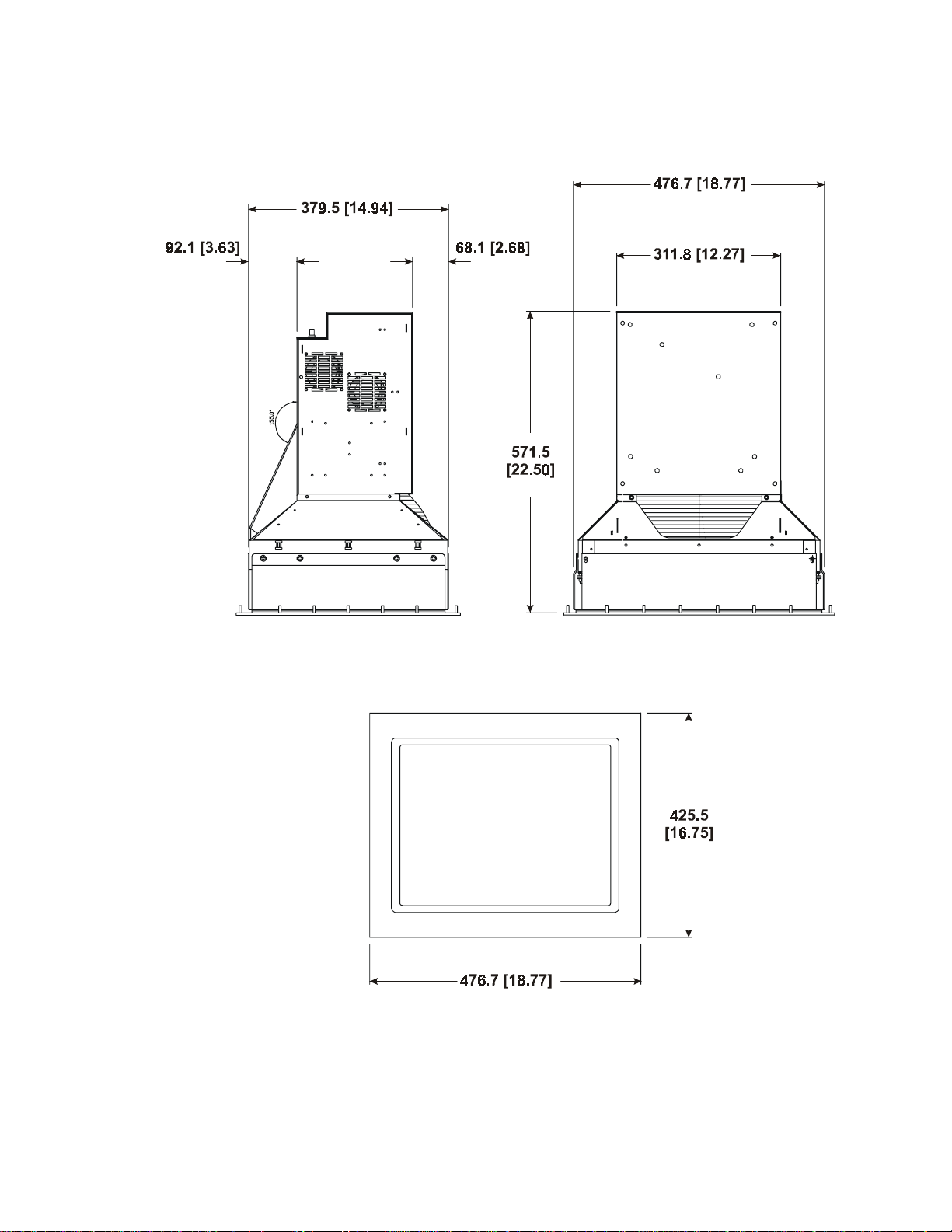
Dimensions
Figure 1
6158 Industrial Monitor - Physical Dimensions
Publication 6158-5.0
Page 6
6 Industrial 21" CRT Monitor
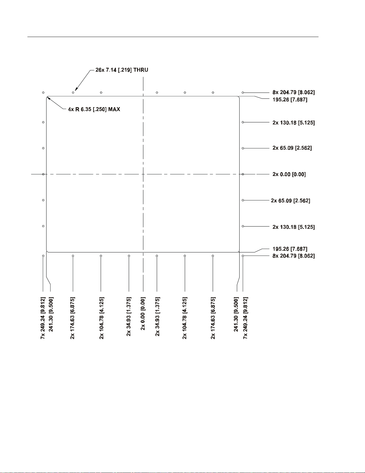
Figure 2
Panel Cutout Dimensions
Publication 6158-5.0
Page 7

Industrial 21" CRT Monitor 7
Installing the 6158 Industrial Monitor
Environmental Considerations
The 6158 Industrial Monitor requires a minimum free air space of 76.2
mm (3 in.) behind and 50.8 mm (2 in.) above and below for proper
cooling. A llen-Bradley I ndustria l Monitors have b e e n de sig ned to
function with out coo l ing fa ns. T herefore, maintenanc e o f f an filters and
access to them n eed not be a concern.
Str ong magnetic fields near the front of the mon i tor outsid e the enclosure
could potentially distort the image over time. This type of image
distortion generally disappears after degaussing occurs. Allen-Bradley
industrial monitors automatically degauss each time AC power is
applied, or whe n the de gauss but ton is press e d.
Note:
The internal degauss will not prevent color impurities
caused by local magnetic fields. Make certain the monitor’s
enclosure is free of residual mag n etism.
Installation Instructions
The 6158 Industrial Monitor has a 9U panel height and is designed to
meet N EMA 4 and NEMA 12 st andards whe n properly installe d.
The panel on which you mount the monitor should be at least 14 gauge
to insure a NEMA 4 seal and proper support for the unit. The mounting
studs attached to the rear of the monitor bezel will accommodate this
minimum thickness panel and panels up to 6.35 mm (0.25 in.) thick.
The monit or may also be bo l ted to the front r ails of EIA standard 19 in.
rack cabinets.
To install the 6158 Industrial Monitor:
1. Confirm that the shipping carton contains a package of 20 10–32
loc k nuts and 20 flat wa shers. You will nee d 18 nut s and washers for
installation.
2. Refer to th e physic al dimension drawings (Figure 1 ) and co nfirm
that there is adequate space behind the panel. Remember to allow
extra space for air circulation.
3. Refer to the pa nel cutout drawing (Figure 2) for dimensions of the
panel cutout and mounting hole locations . Cut and dri ll the panel.
4. Carefully remove the monitor from its packaging. Avoid damaging
the monitor gasket.
Publication 6158-5.0
Page 8
8 Industrial 21" CRT Monitor
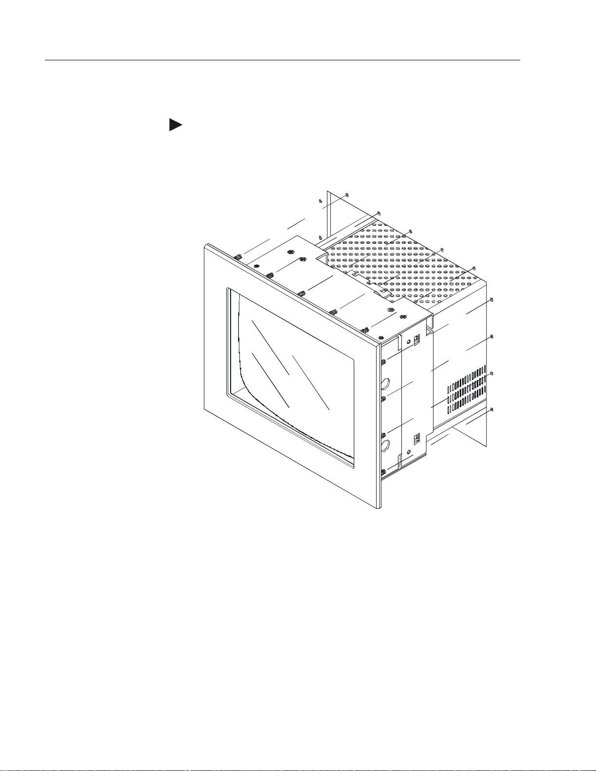
5. Insert the monitor in the panel cutout from the front (Figure 2). Do
not damage the threaded mounting studs as you position the monitor.
Tip: It will be easier to install the monitor if you support it with a shelf
or other support adjusted to the appropriate height.
Figure 3
Generic Panel Mount Diagram
Publication 6158-5.0
Page 9

Industrial 21" CRT Monitor 9
6. Secure the unit with the locknuts and washers provided. Tighten
evenly to 24 inch–pounds of torque.
Important:
To assure a proper seal, be sure to install a washer and nut
on each of the 18 mounting studs.
ATTENTION: Mounting nuts must be tightened to a
torque of 24 inch–pounds to provide panel seal and avoid
pot ential damage. Rock w e ll Automation ass umes no
responsibility for water or chemical damage to the
monitor or other equipment within the enclosure due to
improper installation.
7. Remove the protective adhesive sheet from the screen of the
industrial monitor. The sheet is designed to prevent scratching of the
polycarbonate screen protector or the optional touchscreen during
shipping and ins tallation. It should be remove d before us e.
Publication 6158-5.0
Page 10

10 Industrial 21" CRT Monitor
Connecting AC Power
The 6158 Industrial Monitor requires a single phase power supply
providing 100 to 250V AC at 50 to 60 Hz. Power must be available at a
grounded three–pin outl et located near by. Whenev er poss i ble, c onnec t
the monitor to the same AC source that supplies the computer.
Allen-Bradley monitors automatically adjust to the line voltage and
frequency supplied t o them ( w ithin t he limits sp ec ified) . No switches or
jumpers need to be changed to match the monitor to the voltage supply.
To connect AC power to the monitor:
1. Turn off the mai n switch or breaker.
2. Use the GND point on the rear panel of the monitor to establish a
chassis to earth ground connection. Secure one end of a ground strap
to the GND point. Connect the other end of the ground strap to a
good earth ground.
The ground terminals are M5 screws.
ATTENTION: Chassis ground must be connected for
safe operation of the monitor. The AC receptacle on the
monitor is a 3–wire type with chassis ground pin, and the
mating AC cord supplied is a 3–wire type, designed for
connection to a grounded 3–pin AC outlet. However a
properly grounded AC out let is n ot always a vailab le, a nd
grounding using a 3–wire cord can easily be defeated.
Product Options
If you fail to ground the monitor properly, the setup may
resu lt in p ersona l injury from e lectric al shock or damage
to equipment.
3. Connec t the socket end of the AC power cord to the mat ing
connector on the rear panel of the monitor. Position the power cord
retaining clip attached to the rear panel connector over the cord’s
socket to secure it in place.
4. Connect the plug end of the AC power cord to the mains outlet.
5. Restore AC power to the outlet.
The 6158 Industrial Monitor can be configured with the following
options.
VGA HD-15 or RS-343 BNC video cables
•
touchscreen
•
Publication 6158-5.0
Page 11
Industrial 21" CRT Monitor 11
Video Cables
The monit or ca n be configured with var i ous in dustrial grade v ideo
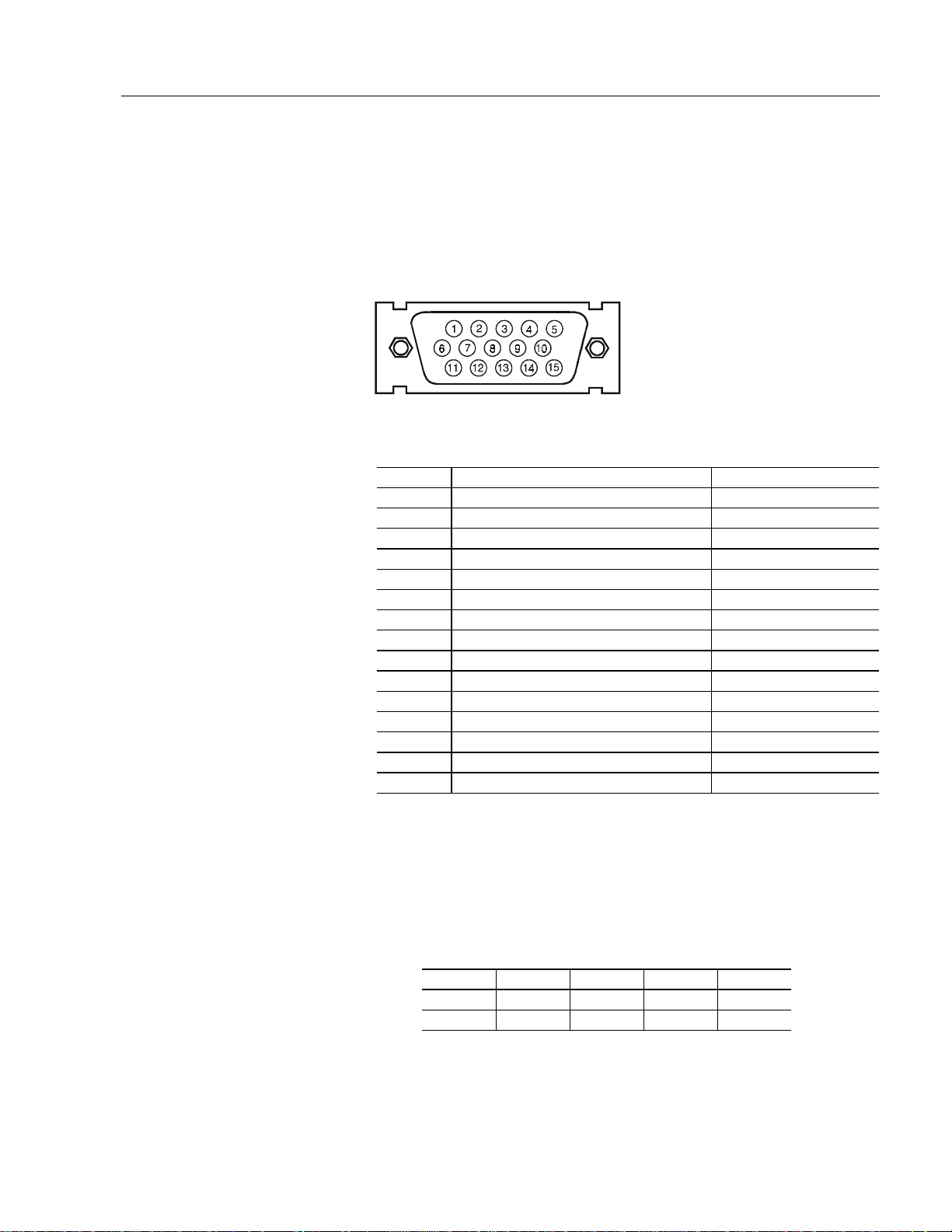
cables. The standard HD-15 cable is equipped with a conventional HD15 connector at each end.
Figure 4
HD-15 Video Cable Connector
Table A
HD-15 Connector Pin Assignments
Pin Signal Description
1 Red Video Input, analog
2 Green Video Input, analog
3 Blue Video Input, analog
4 ID2 Output, TTL l o w
5 Composite Sync Input, TTL, pulsed
6 Red Video Return
7 Green Video Return
8 Blue Video Return
9 Reserved
10 Ground
11 ID0 Output, TTL low
12 ID1 Output, TTL floating
13 Horizontal Sync Input, TTL, pulsed
14 Vertical Sync Input, TTL, pulsed
15 Reserved
1
Monochrome video generator s should present video to this pin. Composite
sync may be presented to this pin together with green or monochrome video. In
this case, the monitor’s sync selector switch must be set to “Sync on Green.”
1
2
2
With a VGA adapter, the polarizati on of thi s signal, together with the
polarization of the vertical sync signal, vary with the adapter’s operating mode,
as shown in the table below. This mode information is not needed by the
monitor, since it is a variable scan monitor.
Signal Mode 1 Mode 2 Mode 3 Mode 4
H Sync + - - +
V Sync - + - +
Publication 6158-5.0
Page 12

12 Industrial 21" CRT Monitor
Another low noise video interface is the Differential BNC Input
connectors option which accept s red, gree n and blue video signal s (RS –
343 analog signaling) and a separate composite sync signal from the
video source. BNC to BNC cable options are available.
Touchscreen Option
The touchscreen option (6158-xxAxxxxxx) provides an anti-glare
touchscreen system. A software driver provid ed wit h the touchscreen
option allows you to use the touchscreen as a pointing device with many
popular DOS and Windows–based industrial applications. Refer to the
touchscreen documentation for information on installing and using the
touchscreen.
Touchscreen Serial Cable
For units conf i gured with the touchscreen option, a t ouchscreen serial
cable is required. A suitabl e cable can be obtained fro m your Rockwell
Automation sales representative.
The cable provides a communication channel between the touchscreen
controller, which is mounted inside the monitor, and an RS-232-C serial
port on the host computer. The touch controller is provided with power
from the monitor ’s power supply. Accordingly, no external touch power
connections are necessary.
The touch controller is set up to detect the baud rate used by the host. For
additional information on controller configurations, please refer to the
documentation provided with the touch system.
Publication 6158-5.0
Page 13

Industrial 21" CRT Monitor 13
Cable Connectors
The following diagram and table indicate the pin configuration of the
DB9 cable connector and the signals assigned to those pins.
12345
6789
DB9
Monitor Signal Connect to Host DB-9 DB-25
1FG 1 8
2 TX Data (output) RX Data (input) 2 3
3 Not Connected 3 2
4 DSR (input) DTR (output) 4 20
5SG SG 5 7
6 DTR (output) DSR (input) 6 6
7 CTS (input) RTS (output) 7 4
8 RTS (output) CTS (input) 8 5
9 x level RI
VIEW LOOKING INTO
PIN END OF MALE CONNECTOR
SOLDER TERM END OF FEMALE CONNECTOR
OR
Touchscreen Software
Prior to using the touchscreen, you must install the touchscreen driver
software on the host computer and perform a calibration procedure.
Details for installation are covered in the documentation that is provided
with the touchscreen system.
Everything you need to install the touchscreen driver software is
included in th e tou chscreen software packet provid ed wit h the s ystem. It
contains a utility pro gram that makes inst allat ion very eas y. Before
attempting to install the touchscreen software, ensure that the version of
the operating system running on the target machine is compatible with
that required by your particular touchscreen system. There are a few
things the user must know about the touchscreen hardware configuration
of the touch system in order to install the driver properly.
The type and model of touch control ler being used.
•
The COM port in use for the touchscreen. Ensure that the RS-232
•
cable is properly installed between the monitor port and the host’s
COM1 or COM2 port. Note the COM port being used.
The touchscreen controller detects the baud rate of the host’s COM
•
port and automatically adjusts to that rate.
The installation procedure involves transferring driver files from the
diskette supplied with the touch system to the host computer’s hard disk,
and adding instructions to system startup files that will load the drivers
following system boot-up. The installation utility automates the transfer
Publication 6158-5.0
Page 14

14 Industrial 21" CRT Monitor
process and crea tes a special directory on the hard di sk to hold the touch
softwar e. The user may spec ify a directory path name; otherwis e, a
default path name is used. In addition, the utility modifies the system
startup files appropriately.
Touchscreen Calibrati on
After installing the driver software, follow the instructions in the
manufacturer’s documentation provided with the touch system.
ATTENTION: The calibration of the touchscreen will be
invalidated by any subsequ e nt adjustment of th e display
size or position. Insure that the display is properly
adjusted before beginning calibration.
When the touch system is to be used with multiple
applications, and these applications use different video
display modes, the calibration procedure should be
repeated for each mode that is to be used.
Using the Touchscreen with Application Programs
Following the installation of the touch software and calibration, the
touchscreen is ready to use.
Since, in general, the touchscreen emulates a mouse, compatibility issues
can arise in relation to the way the touchscreen emulates mouse buttons,
especially multiple buttons. For a complete discussion of these issues,
and means of reso lving p roblems, s e e the re leva nt sections of the
manufacturer’s documentation.
Polycarbonate Window Option
A polycarbonate window option (6158-xxYxxxxxx) is available for
applications t hat require an added measure of protection f or the monitor
screen.
Publication 6158-5.0
Page 15

Industrial 21" CRT Monitor 15
Connecting to a Computer
Connect the 6158 Industrial Monitor to a computer with the appropriate
video cable. A touchscreen serial cable is required for monitors equipped
with the touchscreen option. To connect your monitor to a computer:
1. Plan the ro ute for the c ables and confirm that the ca bles you have
ordered are long enough for the routing you have chosen.
2. If you are using a standard HD-15 video cable with the monitor,
connect either end of the cable to the 15–pin video input connector.
See the rear panel drawing (Figure 5) to locate the HD-15 connector.
Tighten the captive screws on the cable connector to secure it.
Or
If you are using the optional BNC video interface, connect the ends
of th e BNC vid e o c able to the red, green, blu e and comp osit e s ync
input connectors.
Note:
As the rear panel configurations in Figure 5 indicate,
the monitor is equipped with an HD-15 video
connector. Optionally, it can be equipped with an HD15 connector and four BNC connectors. The HD-15
and the BNC inputs are wired in p arallel an d consti tut e
a single interface.
3. For monitors co nf i gured with the touchscreen option, con nect one
end of the serial t ouc hscreen cable to t h e connector labeled “ AUX1”
on the rear panel of the monitor. Tighten the captive screws to secure
it.
4. Route and secure the cables. In cases where the c able cr o ss es a door
hinge, be sure to leave enough excess cable for a loose fit in all door
positions. The monitor cables are designed to be flexible, so routing
across a hin g e shoul d not r es ult in a pplication failure. The minimu m
recommended bend radius for a video cable is 38 mm (1.5 in.).
5. Connect the standard 15–pin connector end of the video cable to the
computer’s video output connector. Tighten the captive screws on
the cable connector to secure it.
6. Connect the touchscreen cable free end to an appropriate RS–232
communications port on the computer. Tighten the captive screws on
the cable connector to secure it.
7. Coil and secure any extra cable length in a convenient location.
Publication 6158-5.0
Page 16
16 Industrial 21" CRT Monitor
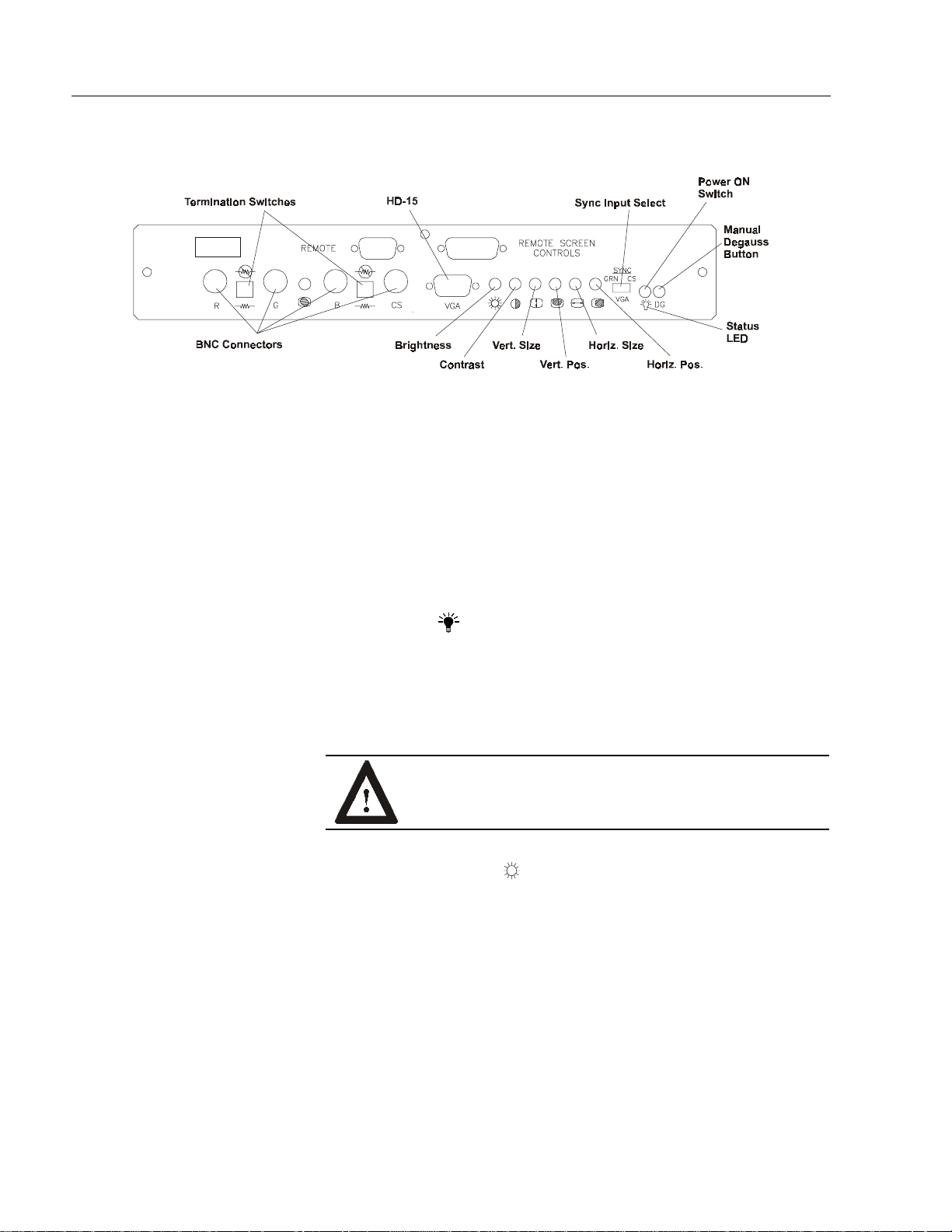
Figure 5
Rea r Panels of M onit or
Rear Panel Controls and Indicators
The rear panel of the 6158 Industrial Monitor contains all of the picture
controls, as well as the power switch and status indicator.
Power Swi tch
Turn on the monitor by pressing the right side of the switch
marked “I”. (Pressing the left side of the switch marked “0” turns the
unit off).
Status LED ( )
When the monitor is powered up and operating correctly, the status
indicator LED (green) will be illuminated. If the light should go out
while the p ower swit ch is in the ”on” pos i tion, a misad just me nt or
malfunct ion has oc c urr e d. Remo ve power immediate ly.
ATTENTION: Do not assume that the monitor is
powered off when the status LED is not lit.
Publication 6158-5.0
Brightness Control ( )
Use the brightness control to adjust the overall intensity of the display.
After allowing the CRT to warm up for at least a minute, adjust for the
least amount of brightness needed to make the display clearly viewable.
Page 17

Industrial 21" CRT Monitor 17
Contrast Control ( )
Use t h e contrast control to vary the differenc e between the d i spla y’s light
and dark el e me nts. With a suitable image displaye d on the sc reen, adjust
th e contrast control to a chieve t he best balanc e between imag e bri ght ness
and fine detail rendition. The optimum setting may vary slightly with
different types of displays and changes in ambient lighting, as well as
individu al taste.
Manual Degaussing Button ( )
The display screen is degaussed automatically each time the monitor is
powered on. This degaussing eliminates color impurities and other
distortions of the display by neut ralizing the eff e c ts of magnet i c fiel ds in
the surrounding environment.
When the unit is left on for a long period, or is repositioned following
power-up, the screen may pick up additional magnetic flux, causing
colors to appear ”blotchy” or otherwise distorted. If this happens,
dega uss t he scre e n manua lly by p ress ing th e d e gaussing bu tto n. For f ull
effectivenes s , allow at least fifteen minutes between manua l degau s s ings.
Shor ter interval s may result in an incompl ete re moval of f lux an d
residual color impurities. If the unit is located near electric transformers,
motors, loudspeakers or other strong magnetic sources, degaussing alone
may not be sufficient to eliminate interference. Try reorienting the unit
relative to the magnetic source or moving the monitor further away.
Vertical Size ( )
Use this control to make the display taller or shorter. Consult the chart
following for recommended display height.
Vertical Position ( )
Use this control to center the display vertically on the screen.
Horizontal Size ( )
Use t h is control t o make the display w ider or narrower. Consult the cha rt
below for recomm e nded d isplay width.
Horizontal Position ( )
Use this control to center the display horizontally on the screen.
Publication 6158-5.0
Page 18

18 Industrial 21" CRT Monitor
Maintenance
Preparation for Shipment
If it is ever necessary to ship the monitor, first remove it from the panel
in which it has been installed, then securely pack it. To remove the
monitor from the panel, reverse the installation procedure that begins on
page 7. Whenever possible, ship the monitor in its original container.
ATTENTION: Never try to ship the monitor while it is
mounted in a panel. Doing so could result in damage t o
the panel or monitor.
Cleanin g in str uction s
Occasionally clean the monitor panel and cabinet with a soft cloth
dampened (not soaked) with a mild household detergent (non-abrasive).
Ensu re tha t air vents a re clea red of dust .
The sc reen may be clean e d with a soft cloth dampen e d with a mild glass
cleaner. Ke ep tur ning a fresh s ide of the cloth toward the scre e n sur f ace
to avoid scratc hing it wi th acc umulated gr it. To minimize the risk of
abrasion, allow the screen to sta nd dry.
Special ca re shou ld be taken when cl eanin g a resistive touc hscr e e n or
polycarbonate shield that is installed over the CRT screen. The surface
can be easily damaged by abrasive and certain chemical cleaners. Never
use alcoholic or ammoniac cleaners.
Replace air filters over fans or heat exchanger intakes periodically to
ensure proper air flow for cooling. (Applicable to units in some industrial
enclosures.)
Publication 6158-5.0
Page 19

Industrial 21" CRT Monitor 19
Allen-Bradley Support
Allen-Bradley offers support services worldwide with over 75
sales/support offices, 512 authorized distributors, and 260 authorized
system integrators located throughout the United States alone, p l us
Allen-Bradley representatives in every major country in the world.
Local Product Support
Contact your local Allen-Bradley representative for:
sales and order support
•
product techni c al training
•
warranty support
•
support service agreements
•
Technical Product Assistance
If you need to contact Allen-Bradley for technical assistance, please
review the information in the Troubleshooting section first. Then call
your local Allen-Bradley representative.
Publication 6158-5.0
Page 20

20 Industrial 21" CRT Monitor
Troubleshooting
The following table can help you identify the potential cause of problems
you may encounter while using the 6158 Industrial Monitor.
Symptom Possible Proble m Action
Status LED does not come on when
power switch is closed.
Status LED is on, but screen is blank. Screen saver activated Disable screen saver by activating an input to
No raster vis i ble even when br ig ht ness
and contrast controls are set full CW.
Raster di m l y vis ib l e wit h br ig htness and
contrast controls set full CW, but no
displ ay pr esent
Display is pr esent, but gar bl ed or r olling. Monitor n ot s ynched to video s ource. Refer to ins t allation inst r uc ti ons .
Display is present and stable, but appears
“wrapp ed” at on e si d e or oth er wise not
properly centered or sized.
Display is present and stable, but missing
some co lor(s)
Display is present and stable, but colors
are not pur e
Display is pr esent, but “jit ters” or is
severely distorted
NOTE: Do not confuse the flicker
associated with an in t erlaced vid eo m od e
with jitter.
Display is present, but “bars” appear
across it.
Power cord not connected. Open power switch. Reconnect power cord at
No power available at AC outlet.
Power cord faulty. Replace power cord.
Monitor f aulty. H ave monitor serviced.
Bright n ess and c ontrast contr ols n ot
proper l y adj us t ed
Monitor ou t of ad jus t ment or fault y H ave m onitor serviced.
Video cable problem
Fault in vid eo s our ce
Fault in mon itor Have moni tor servic ed.
Size and pos it ion controls misadjusted.
Video cable problem Check for proper video cable installation.
Fault in monitor. Have monitor serviced.
Monitor requires degaussing Manually degauss the monitor. Refer to
Interf eri ng external AC or DC m agn et ic
shield
“Nois e” gen erated by oth er equ ip m ent
in the environment is present at the
video inputs
monitor an d at AC out l et . Close power sw itc h.
Test AC outlet by plugging in a lamp or other
known good devic e.
the host system.
Turn brightness and contrast controls CW.
Check for proper installation of video
cable(s). Refer to installation instructions.
Replace suspected faulty cable (s).
Test vid eo s our ce by connect in g to an other
monitor that is known to b e operational.
Check for proper video cable installation.
Replace suspected faulty cable.
Check to ens ure that video s ource is
operating within th e m on it or ’s range.
Adjust c ontrols for pr op er siz e an d p osit ion of
displ ay. R ef er t o op erator instr uc ti ons .
If using BNC inputs, test monitor as follows.
Disconnect sig nal cable(s) corresponding to
the missing color(s). Disconnect signal cable
corresp onding to a disp l ay ed c ol or an d
connect it to the input(s) corre s ponding to the
missi ng color(s). If a missing color reappears,
the signal cable corresponding to that color is
faulty; otherwise, the monitor is faul t y.
Replace suspected faulty cable.
operat or ins tructions .
If possible, reposition the monitor beyond the
proximity of large transformers, motors, bus
bars, etc.
Consult t h e app lication note which disc us ses
method’s of eliminating noise using the
monitor ’s dif f erential inpu ts .
Publication 6158-5.0
Page 21

Specifications
Industrial 21" CRT Monitor 21
Display
CRT Type 21in. diagonal, flat square, 0.28mm, MSP phosphor,
52.3% glass, ARAS coating, INVAR shadow mask,
DAF electron guns, Tension-band implosion protected
Degauss in g Manual and au t om at ic
Image Size (4:3 Aspect) Horizontal 15.3in. (389mm)
Vertical 11.5in. (292mm)
Image Size (5:4 Aspect) Horizontal 14.4in. (365mm)
Vertical 11.5in. (292mm)
Non Linear i t y (CH P M et h od ) Hori z ont al 5% max
Vertical 4% max
Pincus hi on Horiz ont al 3mm max
Vertical 4mm max
Keyston e Horiz ont al 1% max
Vertical 1% max
Regul ati on 2mm max p eak d eviation
Misconvergence 0.3mm max inside ce ntered circle 285mm dia.,
0.4mm m ax ou tside
Lumin ance 30 fL, small wh it e squ are
Lumin ance Uniformi ty Corners at leas t 70% of cent er
CIE coordinates for white x:0.281, y:0.311 (9300K)
Video
Supported Standards IBM VGA (640x480 at 60Hz; VESA 640x480 at
Deflect i on Frequenc i es Horiz ont al Variable: 30kHz to 82kH z
Retrace Times Horizontal 2.8usec min.
Amplifier Bandwidth 150MHz
Black Level Stability Within 1%
Input Signals Video: RGB analog (white level = 0.714V above ref.
Standard Input Connection HD-15 (RGB, HS, VS)
Optional Input Connection HD-15 (RGB, HS, VS) and 4 BNC (RGB, CS)
Operator Controls
Rear Panel Degauss, Brightness, Contra st, H Size, H Position, V
60/72Hz, 800x600 at 56/60/72Hz, 1024x768 at
60/70H z; DEC 10 24 x8 64 at 60Hz, 12 80 x1024 at
66/72Hz; SUN 1152x900 at 67/76Hz; SG/IBM RISC
1280x1 02 4 at 60H z; HP 700 1280 x1 024 at 72Hz, IB M
RISC 1280x1024 at 77Hz
Vertical Variabl e: 40Hz to 80H z
Vertical 0.475msec min
black, in t o 75 Oh ms , dif f er ent ial), Std. Sync : H and V
separate (TTL levels), Sync with BNC Opt.:
Compos ite on green video (0.286V b elow ref. blac k)
or Composite separate (into 75 Ohms differential)
Size, V Position. BNC Option only: Sync Input
Select, RGBS Termination Switches
Publication 6158-5.0
Page 22

22 Industrial 21" CRT Monitor
Environmental
Temperature Operating 0C to 50C
Relati ve Hu midity 10% to 90% n on- condensi ng
Altitude Operating 0 to 10,000 ft (3000m)
Elec trostatic Discharge Operating 8.0KVDC (IEC 801-2, level 3)
Vibration Operating 0.01in. p-p, 5-44Hz sine,
Shock Operating 15g (1/2 sine, 11msec)
X-ray Emissions Designed for compliance with DHHS CFR 21.1020
ELF/VLF Emissions Designed for compliance with MPR-II
Electrical
Line Volt age 90-264VAC
Line Frequency 45- 70Hz
Ground Leakage 1.0 uA max at 1.5KVDC
Power Consumption 135W max
Non-Operating -30C to 65C
Non-Operating 0 to 40,000 ft (12000m )
Non-Operating 20.0KVDC
1.0g peak, 44-500Hz sine
Non-Operating 0.02in. p-p, 5- 4 4H z sin e,
2.0g peak 44-50 0Hz sine
Non-Operating 25g (1/2 sine, 11msec)
Cables
Standard None
Optional US Power Cord (0E2101), 6ft
VGA Cable (0E2003)
Physical
Dimensions 20.5inW x 16.8in.H x 22.5in.D
(514mm x 423mm x 572mm)
Net Weight 70lb (32kg)
Warranty
Standar d 12 months
Option al Extensi ons av ai lable
MTBF
>55,000 hour s at 25C,
Ground B enign
Certification s
UL 1950 Recognized Component,
C-UL 950 R ec og ni z ed C om p onent,
CE97 (89/336/EEC and 73/23/EEC),
FCC Class A
Publication 6158-5.0
Page 23

Industrial 21" CRT Monitor 23
Publication 6158-5.0
Page 24

IBM is a registe red trademark of Inte rn ational Business Machines Corporation.
VGA is a trademar k of International Business Machines Corporation.
PC AT is a trademark of International Business Machines Corporation.
Microsoft is a registered trademark of Microsoft Corporation.
Microsoft Windows is a trademark of Microsoft Corporation .
Rockwell A utomation h el ps i ts custom ers receive a superior return on their investment by bringing
together leading brands in industri al aut omation, creating a broad spect rum of easy-t o-i ntegrate
products. T hese are supported by local technical resources availabl e worldwide, a gl obal network of
system s olutions provid ers, and the advanced technology resources of Rockwell.
Worldwide representation.
Argentina • Australia • Austria • Bahrain • Belgium • Bolivia • Brazil • Bulgaria • Canada • Chile • China, People’s Republic of • Colombia • Costa Rica • Croatia • Cyprus • Czech
Republic • Denmark • Dominican Republic • Ecuador • Egypt • El Salvador • Finland • France • Germany • Ghana • Greece • Guatemala • Honduras • Hong Kong • Hungary
Iceland • India • Indonesia • Iran • Ireland • Israel • Italy • Jamaica • Japan • Jordan • Korea • Kuwait • Lebanon • Macau • Malaysia • Malta • Mexico • Morocco • The Netherlands
New Zealand • Nigeria • Norway • Oman • Pakistan • Panama • Peru • Philippines • Poland • Portugal • Puerto Rico • Qatar • Romania • Russia • Saudi Arabia • Singapore
Slovakia • Slovenia • South Africa, Republic of • Spain • Sweden • Switzerland • Taiwan • Thailand • Trinidad • Tunisia • Turkey • United Arab Emirates • United Kingdom • United
States • Uruguay • Venezuela
Rockwell Automation Headquarters, 1201 South Second Street, Milwaukee, WI 53204-2496 USA, Tel: (1) 414 382-2000, Fax: (1) 414 382-4444
Rockwell Automation European Headquarters, Avenue Hermann Debroux, 46 1160 Brussels, Belgium, Tel: (32) 2 663 06 00, Fax: (32) 2 663 06 40
Rockwell Automation Asia Pacific Headquarters, 27/F Citicorp Centre, 18 Whitfield Road, Causeway Bay, Hong Kong, Tel: (852) 2887 4788, Fax: (852) 2508 1846
World Wide Web: http://www.ab.com
998055-010
Publication 6158-5.0
Copyright 1999 Rockwell Automation Corporation. All rights reserved. Printed in USA.
•
•
•
 Loading...