

Page 1
Control Module Kit for Bulletin 500LG Contactors
(Cat 500LG_)
WARNING
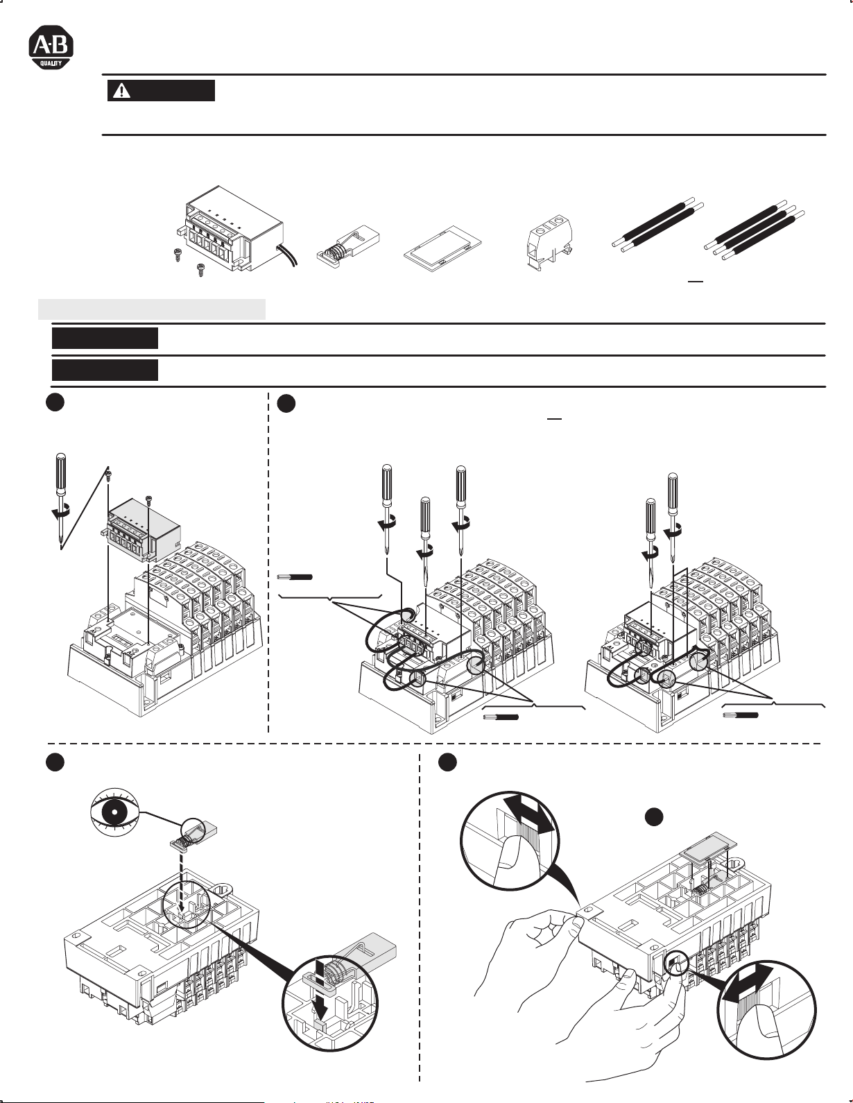
The control module kits are designed for use with Bulletin 500LG lighting contactors only. Control module kits enable conversion of an
electrically held contactor to a mechanically held contactor. These kits are available in either 2-wire or 3-wire control versions in a variety of
voltages. The component parts of a 2-wire control module kit are shown. A 3-wire kit includes an additional single-pole auxiliary contact
block.
To prevent electrical shock, disconnect from power source before installing or servicing. Follow NFPA 70E requirements. Install
in a suitable enclosure. Keep free from contaminants.
Installation or removal of a control module kit to or from the Bulletin 500LG lighting contactor must be performed by a "Qualified
Person" as defined by the National Electrical Code.
Control Module
Control Module Installation
NOTICE
NOTICE
Remove all packing material.
1
Mount the control module on the
contactor.
7 - 12 lb-in
500LG
The control module kits are for use with the coils up to 277 VAC maximum. Use a control power transformer for higher voltages.
Latch and electronic module must be used together to ensure proper operation. Failure to do so will void warranty.
Latch
For 3-wire control, two auxiliary contact blocks
2
are assembled to the lighting contactor; one on
the right (N.C.) and one on the left (N.O.). Refer
to Table C on sheet 2 for connection diagram.
7 - 12 lb-in
#22 - #12 AWG
(Stranded or Solid)
Latch Cover
7 - 12 lb-in
5 lb-in
500LG
Auxiliary
or
2- Wire
Control
For 2-wire control, one auxiliary contact block is
assembled to the right side of the lighting
contactor base for normally closed (N.C.). Two
wires coming from the control module are
connected across the auxiliary contact block.
Refer to Table A on sheet 2 for connection diagram.
7 - 12 lb-in
5 lb-in
500LG
or
3- Wire
Control
Mount the latch and be sure latch is firmly in place
3 4
with the wire facing out and the slot positioned with tab inserted.
#22 - #12 AWG
(Stranded or Solid)
Operate contactor manually, using manual operation tabs on side
prior to installing cover to ensure correct installation.
Install latch cover.
5
#22 - #12 AWG
(Stranded or Solid)
Operation Tab
Page 2
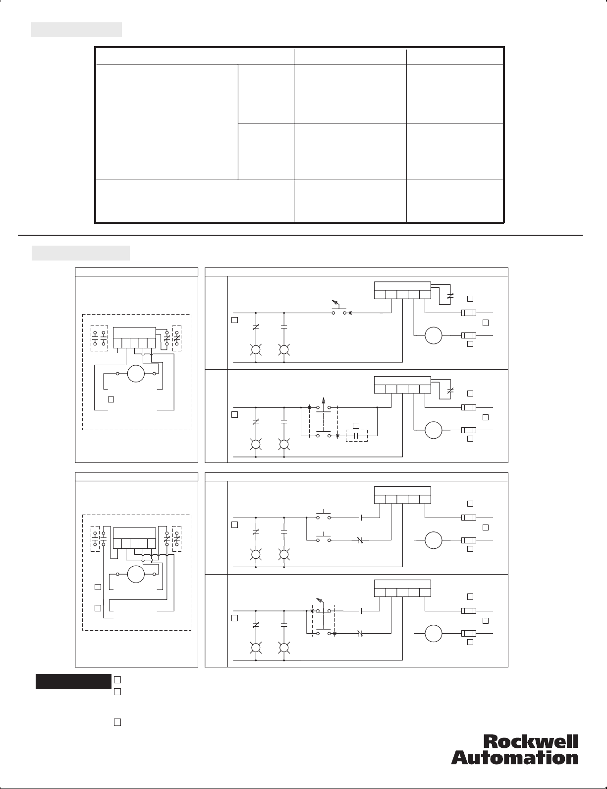
Renewal Parts
Control Module Kit
2 Wire
3 Wire
Voltage Cat. No.
12 - 24 VDC 500LG-47CM12
24 VAC / 60/50 Hz 500LG-47CM24
110 - 120 VAC / 60/50 Hz 500LG-47CM120
200 - 277 VAC / 60/50 Hz 500LG-47CM277
12 - 24 VDC 500LG-48CM12
24 VAC / 60/50 Hz 500LG-48CM24
110 - 120 VAC / 60/50 Hz 500LG-48CM120
200 - 277 VAC / 60/50 Hz 500LG-48CM277
Wiring Diagram
TABLE A: 2-WIRE CONNECTION DIAGRAM
NOT
(OPTIONAL AUX.)
USED
P
3
P
500LG(MECHANICALLY-HELD, 2-WIRE)
TABLE C: 3-WIRE CONNECTION DIAGRAM
(OPTIONAL AUX.)
3
P
3
P
500LG(MECHANICALLY-HELD, 3-WIRE)
ELECTRONIC
MODULE
P2P1A1P4P3
C
COIL
VOLTAGE
CONTROL
VOLTAGE
ELECTRONIC
MODULE
P2P1A1P4P3
C
COIL
VOLTAGE
CONTROL
VOLTAGE
Auxiliary Contact
P5
(OPTIONAL AUX.)
A2
N
N
P5
(OPTIONAL AUX.)
A2
N
N
1 NO / NC 500LG-141C
2 NO / NC 500LG-142C
TABLE B: OPTIONAL WIRING AND PILOT DEVICES FOR MECHANICALLY-HELD CONTACTOR, 2-WIRE CONTROL
1
C
C
C
C
ELECTRONIC MODULE
P1
ELECTRONIC MODULE
P1
ELECTRONIC MODULE
P1
ELECTRONIC MODULE
P1
P4
P2
P3
P4
P2
P3
P4
P2
P3
A2 A1
P4
P2
P3
A2 A1
P5
C
A1A2
P5
C
A1A2
P5
C
P5
C
OFF ON
P
3
CC
(LEFT AUX.)
(RIGHT AUX.)
CONTROL
VOLTAGE
OFF-ON
OFF-AUTO
SELECTOR SWITCH
OFF
N
P
3
HAND-OFF-AUTO
ON-OFF-AUTO
TABLE D: OPTIONAL WIRING AND PILOT DEVICES FOR MECHANICALLY-HELD CONTACTOR, 3-WIRE CONTROL
ON-OFF
PUSHBUTTON
OFF-ON
SELECTOR SWITCH
(RIGHT AUX.)
SELECTOR SWITCH
CONTROL
VOLTAGE
OFF
N
P
3
(RIGHT AUX.)
CONTROL
VOLTAGE
OFF
N
P
3
(RIGHT AUX.)
CONTROL
VOLTAGE
OFF
N
R
G
ON
CC
(LEFT AUX.)
R
G
ON
CC
(LEFT AUX.)
R
G
ON
CC
(LEFT AUX.)
R
G
ON
OFF
HAND AUTO
OFF
ON
OFF ON
(LEFT AUX.)
(RIGHT AUX.)
(LEFT AUX.)
(RIGHT AUX.)
C
2
FUSE
N
3
FUSE
C
FUSE
FUSE
FUSE
FUSE
FUSE
FUSE
COIL
VOLTAGE
P
2
2
N
3
COIL
VOLTAGE
P
2
2
N
3
COIL
VOLTAGE
P
2
2
N
3
COIL
VOLTAGE
P
2
NOTICE
42052-193-01 (1)
Printed in U.S.A.
1 Remote device
2 Additional Control Circuit Overcurrent Protection may be required when the control circuit conductors extend beyond the
enclosure. Refer to the U.S. National Electrical Code or the Canadian Electrical Code for control circuit protection
requirements.
3 Coil and control voltages may not be the same. Check the voltage of the electronic module and coil before applying power.
 Loading...