

Page 1
Fused Expander Interface Modules
Modules d'interface avec expandeur à fusible
Dynamikdehner-Schnittstellenmodule, Schmelzsicherung
Moduli di interfaccia di espansione con fusibili
Módulos de interfaz del expansor de fusible
(Cat 1492-XIMF-2, -XIMF-F24-2, -XIMF-F120-2)
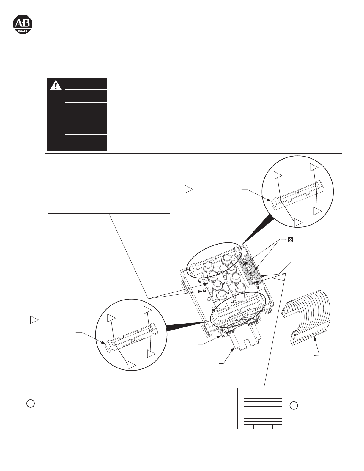
WARNING
AVERTISSEMENT
WARNUNG
AVVERTENZA
ADVERTENCIA
To prevent electrical shock, disconnect from power source before installing or servicing.
device installation in a tool-accessible enclosure compliant with ANSI/ISA S82.
Avant le montage et la mise en service, couper l'alimentation secteur pour éviter toutes décharges.
nécessite l'installation de l'équipement dans une armoire accessible aux interventions, conforme à ANSI/ISA S82.
Vor Installations- oder Servicearbeiten Strom-versorgung unterbrechen, um Elektroschocks zu vermeiden.
Gruppe 2 erfordert die Installation des Gerätes in einem Gehäuse, das für Werkzeuge zugänglich ist und den
Anforderungen gemäß ANSI/ISA S82 entspricht.
Per prevenire infortuni, togliere tensione prima dell’installazione o manutenzione.
l'installazione del dispositivo in un alloggiamento con capacità di accesso per strumenti conforme allo standard
ANSI/ISA S82.
Desconéctese de la corriente eléctrica, antes de la instalación o del servicio, a fin de impedir sacudidas eléctricas.
requisito de FM (Factory Mutual) Clase 1, Div. 2, establece que el dispositivo debe instalarse en un envolvente que
permita la introducción y uso de herramientas y cumpla con la norma ANSI/ISA S82.
Fuse Holders : See page 3 for fuse installation/removal
Porte-fusibles : voir page 3 l'installation et le retrait des fusibles.
Sicherungshalter : Ein- und Ausbau der Sicherung siehe Seite 3\
Portafusibili : vedere il montaggio/smontaggio dei fusibili a pagina 3.
Portafusibles : Vea la página 3 para obtener informaci
instalaci
ó
n/extracción de fusibles.
ó
n sobre la
Expansion Connector
= Connector Pin
= Broche de connexion
= Steckerstift
= Pin del connettore
= Pasador de conector
F15
F14
F12
F13
F11
F10
F8
FM Class 1, Div.2 requires
FM Classe 1, Div. 2
FM-Klasse 1,
FM Classe 1, Divisione 2 richiede
El
33
1
CJ
OUT
34
2
= Field-side Terminals
= Borne exterieure
= Feldseitiger Terminal
Lower = A
F9
B1
A1
= Terminale lato-campo
= Terminal de campo
Upper = B
Expansion Connector
= Connector Pin
= Broche de connexion
= Steckerstift
= Pin del connettore
= Pasador de conector
Adhesive Label Card. Provides terminal wiring identification.
1
Carte étiquette adhésive. Identifie le câblage des bornes.
Aufklebbare Etiketten zur Kennzeichnung der Klemmenverdrahtung.
Scheda etichette adesive. Fornisce l'identificazione del cablaggio dei terminali.
Tarjeta de etiquetas adhesivas. Proporciona identificación de cableado del terminal.
PN-23155
DIR 40063-397 (Version 04)
Printed in U.S.A.
34
2
1492-EAJ35
35 mm DIN Rail
199-DR1
199-DR4
1492-DR7
Expansion Cable
Câble d'extension
Erweiterungskabel
Cavo di espansione
Cable de expansión
1
CJ
IN
33
1
Page 2
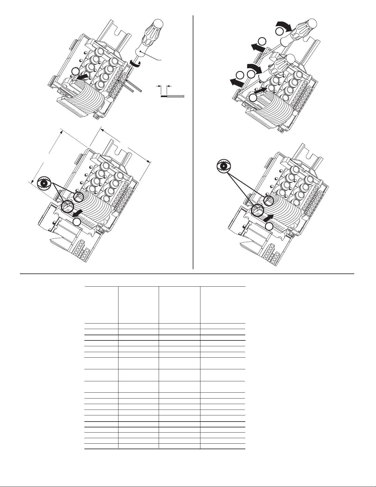
Installation
Montage
Installation
Montaggio
Instalación
W
Removal
Retrait
Entfernen
Smontaggio
6
5
Extracción
1492-N90
3.5-4.5 lb-in
1
H
(0.38-0.50 Nm)
0.32 in
(8 mm)
#22-#12 AWG
2
(0.2-4 mm
)
Cu only
Cu seulement
nur Cu
Solo Cu
Cu solamente
4
3
1
Cable Matrix
Matrice des câbles
Kabelmatrix
Matrice cavi
Matriz de cables
2
I/O Module
Module E/S
E/A-Modul
Modulo I/O
1492-XIMF-F24-2 1492-XIMF-F120-21492-XIMF-2
Módulo de E/S
1746-OA16
1746-OB16
1746-OB32
1746-OB16E
1746-OB32E
1746-OBP16
1756-OA16
TC-ODA161
1756-OB16E
TC-ODD161
1756-OB32
TC-ODD321
1769-OB16
1769-OB32
1769-OB32T
1769-OA16
1771-OAD
1794-OB16
1794-OB16P
1794-OB32P
2
Can have up to 3 expandable modules depending upon master used.
Possibilité de 3 modules extensibles selon le maître utilisé
Kann je nach verwendetem Master bis zu 3 erweiterbare
Module aufweisen.
Possono avere un massimo di 3 moduli espandibili a seconda del
master usato.
Puede tener conectados hasta 3 módulos expansibles, según el
dispositivo maestro que se utilice.
Can have one expandable module per master.
Possibilité d'un seul module extensible par maître
Kann ein erweiterbares Modul je Master aufweisen.
Possono avere un modulo espandibile per master.
Puede tener conectado un solo módulo expansible por cada
dispositivo maestro.
Cable is limited for use within the control panel unless it is run
through conduit. Cable is ITC (Instrumentation Tray Cable) rated.
PN-23155
DIR 40063-397 (Version 04)
(2)
Page 3
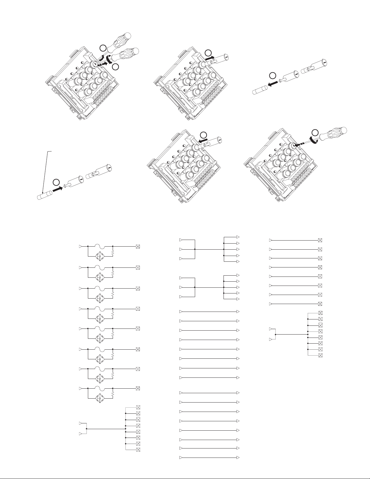
Fuse Installation / Removal
Installation
/
retrait des fusibles
Ein- und Ausbau der Sicherung
Montaggio
/
smontaggio dei fusibili
Instalación
/
extracción de fusibles
5 x 20 mm
(max. 2.0A per circuit; 12A per module)
(max. 2,0 A par circuit; 12 A par module)
(max. 2,0 A pro Stromkreis; 12 A je Modul)
(max. 2,0 A per circuito; 12 A per modulo)
(máx. 2.0 A por circuíto; 12 A por módulo)
4
Pinout
Brochage
Anschlußbelegung
Disposizione
dei piedini
Esquema de pins
PN-23155
DIR 40063-397 (Version 04)
2
3
F12
F10
F8
F9
F11
1492-XIMF-F24-2
1492-XIMF-F120-2
1
F15
F13
F8
1492-XIMF-F120-2 (Continued)
CJ
CJ
IN
16
12
8
6
4
3
2
1
27
28
F8
F9
F10
F11
F12
F13
F14
F15
TB
30
B1
B2
B3
B4
B5
B6
B7
B8
A1
A2
A3
A4
A5
A6
A7
A8
31
32
25
26
29
24
23
22
21
20
19
18
17
15
14
13
11
10
9
7
5
F14
F12
F10
F8
F11
F9
5
F14
F12
F10
F13
F11
F9
1492-XIMF-F24-2
IN
F15
F13
4
6
F12
F15
F10
F8
1492-XIMF-2
CJ
CJ
OUT
1
2
3
4
6
5
7
8
9
10
20
24
28
30
32
31
34
33
14
12
13
16
11
15
18
17
IN
16
12
8
6
4
3
2
1
27
28
F15
F13
F11
F9
TB
B1
B2
B3
B4
B5
B6
B7
B8
A1
A2
A3
A4
A5
A6
A7
A8
(3)
Page 4
I/O Wiring Data
NOTICE
Wiring information for your I/O module, AIFM module and cable (e.g. wiring diagram and pinouts)are available online at www.rockwellautomation.com/en/e-tools.
To obtain information follow this procedure.
1) In the Catalog Number BOX at the above online site type in the catalog number of the IFM, AIFM, etc. module you are using and click on Submit.
2) At the next screen displayed, click on the Modify key (lower left of screen).
3) Click on the areas that indicate NO SELECTION and enter your specific configuration information (e.g. I/O platform, I/O MODULE, ETC.).
NOTE: To obtain the wiring diagram, you must select th Pre-Wired Cable Connector selection.
4) Configure your 1492 cable by filing in the NO SELECTION areas.
5) Click on the ACCEPT key for the configured 1492 cable. At the next screen click on ACCEPT for the 1492 module.
6) The next screen (Configuration Results) displays the results of your specific configuration. The "supplementary Documents" column contains I/O wiring information
for the configuration (e.g. I/O Wiring Diagrams).
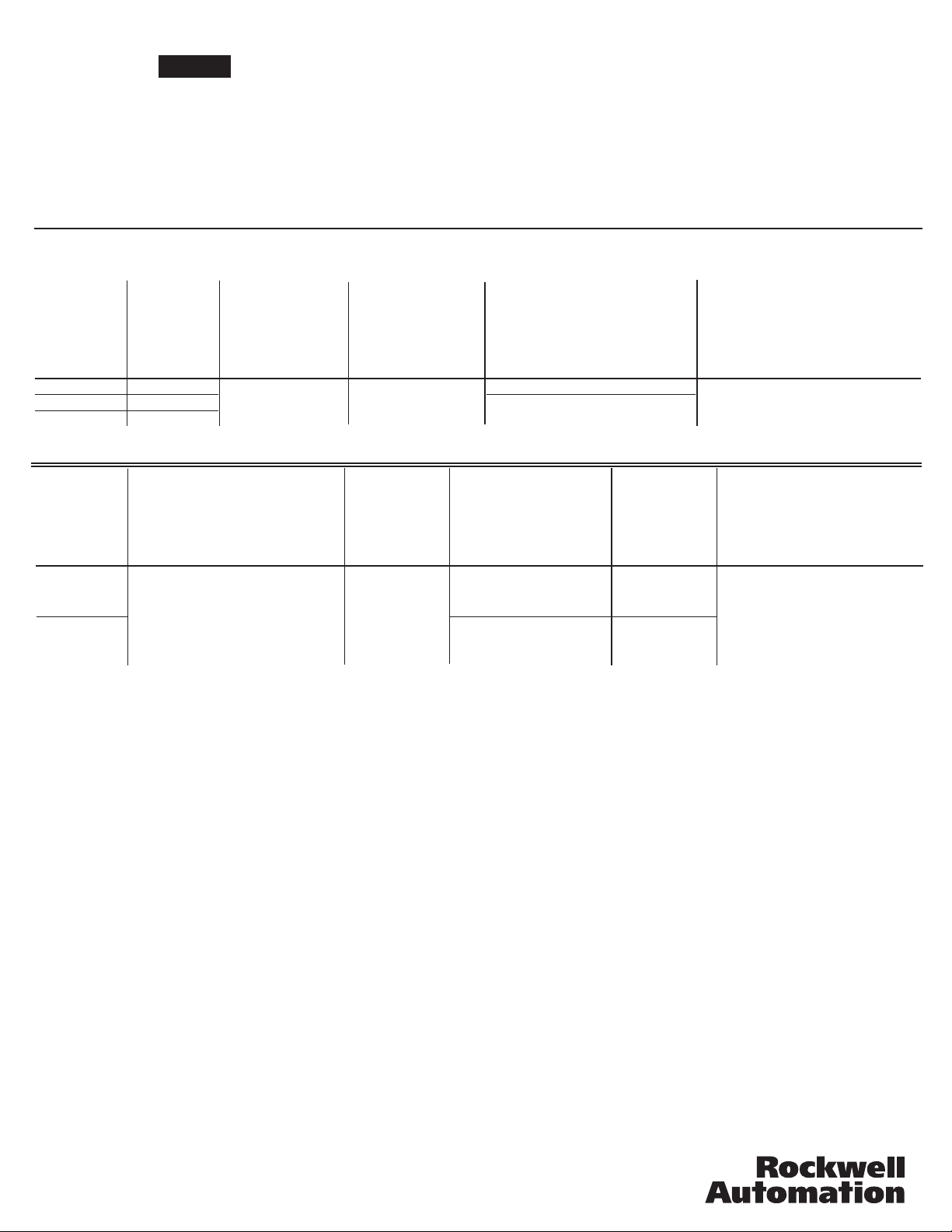
Specifications
Spécifications
Catalog No.
Référence
Bestell-Nr.
N. Catalogo
Referencia
1492-XIMF-2
1492-XIMF-F24-2
1492-XIMF-F120-2
Catalog No.
Référence
Bestell-Nr.
N. Catalogo
Referencia
1492-XIMF-2
1492-XIMF-F24-2
1492-XIMF-F120-2
Technische Daten
Specifiche
Voltage
Tension
Spannung
Tensione
Voltaje
0-132 VAC/DC
10-30 VDC
85-132 VAC
Operating Temperature Range
Plage températures de fonctionnement
Betriebstemperaturbereich
Limiti temperatura di funzionamento
Rango de temperatura de funcionamient
Current / Circuit
Courant / Circuit
Strom / Schaltkreis
Corrente / circuito
Intensidad / circuito
2 Amps
0° C - 60° C
Especificaciones
Current / Module
Courant / Module
Strom / Modul
Corrente / modulo
Intensidad / módulo
4 Amps
Operating Humidity
Humidité relative
Betriebsluftfeuchtigkeit
Umidità di esercizio
Humedad operativa
5 - 95%
Indicator Circuit Current
Courant circuit voyants
Strom, Anzeigeschaltkreis
Corrente circuito indicatori
Intensidad del circuito de
indicadores
N/A
2.0 mA
Approx. Shipping Weight
Poids d'embarquement approximatif
Ungefähres Versandgewicht
Peso approssimativo del carico
Peso aproximado al momento de
embarque
0.58 lb.
263 g.
0.65 lb.
298 g.
Dimensions
Dimensions
Abmessungen
Dimensioni
Dimensiones
3.15 in. (80 mm) W
3.27 in. (83 mm) H
2.19 in (55.5 mm) D
3.15 in. (80 mm) W
3.27 in. (83 mm) H
2.28 in (58 mm) D
Maximum Recurring Peak Voltage
Tension de crele réurrente maximale
Maximale periodische Hochstspannung
Tensione massima di cresta ricorrente
Voltaje de cresta iterativo máximo
p
600 V
Standards
Normes
Standards
Standard
Estándares
cULus (File: E113724, Guide No.: NRAQ)
CE: Compliant for all applicable directives
FM Class 1 Div 2 Groups A, B, C and D
Temperature Rating T3C = 60°C
(J.I. 3000590, all except relay modules)
For transients > 600 Vp use a UL recognized suppression device rated at 2.5 kV withstand.
Pour des transitoires > 600 Vp utilisez un dispositif de suppression certifié UL à 2,5 kV nominal de tenue.
Für Einschaltstöße > 600 Vp verwenden Sie einen UL anerkannten Entstörer, der bewertet wurde bei 2,5 kV standzuhalten.
Per transitori > 600 Vp usare dispositivo di soppressione riconosciuto da UL capace di sopportare 2,5 kV.
Para transitorios > 600 Vp use un dispositivo de supresión reconocido UL clasificado con 2,5 kV.
Non-condensing
Sans condensation
Nicht kondensierend
Senza condensa
sin condensación
SURGE SUPPRESSION follow the literature recommendations of the PLC module being used.
SUPPRESSION DES SURTENSIONS se trouve à la suite de la littérature qui contient les recommandations relatives au module PLC utilisé.
ÜBERSPANNUNGSSCHUTZ Bitte beachten Sie die Dokumentationsempfehlungen für das jeweils benutzte SPS-Modul.
Per la SOPPRESSIONE DEI PICCHI TEMPORANEI, seguire le istruzioni riportate nella documentazione in dotazione al Modulo PLC utilizzato.
SUPRESIÓN DE SOBRETENSIÓN, siga las recomendaciones indicadas en la documentación del módulo PLC respectivo.
Reference Publications: Refer to 1770-4.1 and appropriate PLC I/O module installation manual.
PN-23155
DIR 40063-397 (Version 04)
Printed in U.S.A.
 Loading...